US5821651A - Flywheel controller - Google Patents
Flywheel controllerDownload PDFInfo
- Publication number
- US5821651A US5821651AUS08/642,130US64213096AUS5821651AUS 5821651 AUS5821651 AUS 5821651AUS 64213096 AUS64213096 AUS 64213096AUS 5821651 AUS5821651 AUS 5821651A
- Authority
- US
- United States
- Prior art keywords
- flywheel
- power
- generator
- controller
- range
- Prior art date
- Legal status (The legal status is an assumption and is not a legal conclusion. Google has not performed a legal analysis and makes no representation as to the accuracy of the status listed.)
- Expired - Lifetime
Links
Images


Classifications
- B—PERFORMING OPERATIONS; TRANSPORTING
- B60—VEHICLES IN GENERAL
- B60L—PROPULSION OF ELECTRICALLY-PROPELLED VEHICLES; SUPPLYING ELECTRIC POWER FOR AUXILIARY EQUIPMENT OF ELECTRICALLY-PROPELLED VEHICLES; ELECTRODYNAMIC BRAKE SYSTEMS FOR VEHICLES IN GENERAL; MAGNETIC SUSPENSION OR LEVITATION FOR VEHICLES; MONITORING OPERATING VARIABLES OF ELECTRICALLY-PROPELLED VEHICLES; ELECTRIC SAFETY DEVICES FOR ELECTRICALLY-PROPELLED VEHICLES
- B60L50/00—Electric propulsion with power supplied within the vehicle
- B60L50/30—Electric propulsion with power supplied within the vehicle using propulsion power stored mechanically, e.g. in fly-wheels
- Y—GENERAL TAGGING OF NEW TECHNOLOGICAL DEVELOPMENTS; GENERAL TAGGING OF CROSS-SECTIONAL TECHNOLOGIES SPANNING OVER SEVERAL SECTIONS OF THE IPC; TECHNICAL SUBJECTS COVERED BY FORMER USPC CROSS-REFERENCE ART COLLECTIONS [XRACs] AND DIGESTS
- Y02—TECHNOLOGIES OR APPLICATIONS FOR MITIGATION OR ADAPTATION AGAINST CLIMATE CHANGE
- Y02T—CLIMATE CHANGE MITIGATION TECHNOLOGIES RELATED TO TRANSPORTATION
- Y02T10/00—Road transport of goods or passengers
- Y02T10/60—Other road transportation technologies with climate change mitigation effect
- Y02T10/70—Energy storage systems for electromobility, e.g. batteries
Definitions
- the present inventionrelates generally to powertrain systems in vehicles, and, more particularly, to a hybrid powertrain system in an automotive vehicle.
- alternative fuel powered vehiclesmay be powered by methanol, ethanol, natural gas, electricity or a combination of fuels.
- a dedicated electric powered vehicleoffers several advantages: electricity is readily available; an electric power distribution system is already in place; and an electric powered vehicle produces virtually zero emissions.
- a hybrid powertrainwhich incorporates a high efficiency generator, an electric motor and a flywheel for an automotive vehicle which capable of performing as dynamically as an internal combustion engine.
- a flywheel controllerfor commutating a stator of a flywheel.
- the flywheel controllerincludes a sensing unit to sense rotation of the stator and for creating a rotational speed signal based on that rotation.
- a controlleris operatively connected to the sensing unit and creates a command signal.
- the flywheel controllerincludes a commutator operatively connected to the controller for receiving the command signal to commutate the stator.
- the commutatorincludes a pulse width modulator for controlling power to the flywheel over a first predetermined power range and a step generator for controlling power over a second predetermined power range.
- One advantage associated with the present inventionis the ability to control a flywheel in an automotive vehicle.
- Another advantage of the present inventionis the ability to commutate a stator in a flywheel over an extended range of rotational speeds by monitoring the rotational speed of the rotor using at least two separate and distinct devices.
- FIG. 1is a perspective view partially cut away of an automotive vehicle.
- FIG. 2is a block diagram of the power train for the automotive vehicle.
- FIG. 3is a block diagram of one embodiment of the flywheel controller.
- FIG. 4is a block diagram of one embodiment of the commutator of the flywheel in relation to the controller thereof.
- FIG. 5is a graphic representation of the output of the step generator.
- FIG. 6is a graphic representation of the output of the notch generator.
- FIG. 7is a graphic representation of the combination of the outputs of the step generator and the notch generator.
- FIG. 8is a graphic representation of the resultant line to neutral switching output pattern applied to the flywheel based on the input of FIG. 7.
- FIG. 9is graphic representation of the root mean squared of the power output as a function of excitation angle.
- FIG. 10is a graphic representation of the power output based on excitation angle control.
- FIG. 11is a flow chart for a method to accurately estimate the rotational speed of the rotor of the flywheel.
- FIG. 12is a block diagram of a control unit of one embodiment of the present invention.
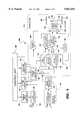
- FIG. 13is a block diagram schematic of the encoder and pulse width modulator of one embodiment of the present invention.
- FIG. 14is a flowchart of the processor operation required to command center aligned pulses to the pulse width modulator.
- a hybrid powertrain systemis illustrated for an automotive vehicle 20.
- the vehicle 20is partially shown in a cut away view illustrating a hybrid powertrain system 22 disposed within the chassis 24.
- the hybrid powertrain system 22includes a gas powered turbine engine 26, which in this example is fueled by liquefied natural gas.
- the turbine engine 26spins an alternator 28 to generate electric power.
- alternator 28to generate electric power.
- the turbine engine 26 and the alternator 24may be referred to as a turboalternator.
- a power controller 38is in communication with the turbine engine 26 and alternator 28, and manages the distribution of power from the alternator 28 to a traction or induction motor 32 using a power transfer mechanism 34, utilizing a three phase variable frequency alternating current (VFAC).
- VFACvariable frequency alternating current
- the traction motor 32is an AC induction traction motor 32.
- the traction motor 32transfers its energy to the drive train 36 to drive the automotive vehicle 20.
- a signal from a vehicle management controller 30 to accelerate the automotive vehicle 20is communicated to the power controller 38.
- the power controller 38directs the alternator 28 and if necessary a flywheel 40, to supply power to the traction motor 32 and eventually to wheels 42. If the power need of the traction motor 30 is low, the power controller 38 directs the excess power capacity into the flywheel 36 for storage.
- the hybrid powertrain system 22also includes various critically placed sensors which are conventional and well known in the art. The outputs of these sensors communicate with the power controller 38. It should also be appreciated that the automotive vehicle 20 includes other hardware not shown, but conventional in the art to cooperate with the hybrid powertrain system 20.
- a flywheel controlleris generally indicated at 100.
- the flywheel controller 100controls the output of a flywheel 102.
- a sensing unit 104senses the rotational position of the flywheel 102.
- the sensing unit 104a position sensor, transmits a signal over line 106 to a control unit 108.
- the position sensor 104is shown as an encoder in FIGS. 4 and 13, it should be appreciated to those skilled in the art that any type of position identification may be used.
- the control unitis operatively connected to the sensing unit 104.
- the control unit 108creates a command signal indicative of the power desired to be absorbed by the flywheel 102 or, in the alternative, supplied by the flywheel 102 for the purpose of balancing the power flow in the system.
- the control signalis sent to a commutator 110.
- the commutator 110is operatively connected to the controller 108 and receives the command signal therefrom.
- the commutator 110commutates electrical signals to the stator (not shown) of the flywheel 102.
- the commutator 110also includes a pulse width modulator 116.
- the pulse width modulator 116controls the power output from the flywheel 102 over a first predetermined flywheel speed range.
- the range in which the pulse width modular operatesis between 0 RPM and 15,000 RPM.
- the commutator 110also includes a six step generator 112.
- the six step generator 112controls the power from the flywheel over a second predetermined flywheel speed range. More specifically, the six step generator 112 provides a voltage signal to an AC or voltage bus 114 to control the output of the flywheel 102 to regulate the output thereof.
- the second predetermined flywheel speed rangeis approximately from 29,000 RPM to 58,000 RPM.
- the flywheel controller 100incorporates the use of a notch generator 118 within the commutator 110.
- the notch generator 118injects a notch into the six step pattern for the purpose of voltage control.
- the notch generatoris used in combination with the six step generator 112 to enlarge the second predetermined flywheel speed range. More specifically, the notch generator 118 allows the step generator 112 to control power from the flywheel over into a third predetermined flywheel speed range which is an extension of the second predetermined flywheel speed range.
- the notch generator 118can be thought of as being operable in the second range, albeit a larger second range, but set for a zero angle output. This third predetermined range extends between 15,000 RPM and 29,000 RPM.
- the commutator 110includes a signal combiner 120.
- the signal combiner 120combines the output of the six step generator 112 and the notch generator 118 before it is received by the voltage bus 114 to control the voltage applied to flywheel 102, the output of which is shown in FIG. 7.
- the flywheel controller 100receives a digitized signal from the DC bus 121 as it passes through an A/D converter 123 through an uplink connection 125.
- the control unit 108controls a sample rate generator 127 which directs the A/D converter 123 in its generation of data. It may be appreciated by those skilled in the art that the DC bus 121 is not connected directly to the A/D converter 123, but only after the voltage has been reduced from the 800 V through means well known in the art.
- An encoder interface 129receives two inputs A and B, representing phase and quadrature of position increments of the rotor.
- the encoder interface 129a device known to those skilled in the art, converts the A and B signals into a position signal.
- the output of the encoder interface 129is sent to the uplink connection 125 and into the control unit 108.
- the control unit 108can also determine, based on whether successive position inputs are increasing or decreasing, the direction of the movement of the rotor in the flywheel 102.
- the control unit 108Upon determining the proper control commands for the flywheel controller 100, the control unit 108 sends a signal down through a downlink connection 122.
- the downlink connection 122sends a signal to one of several points.
- the first of whichis a pulse width modulator 124.
- the pulse width modulator 124controls the power output from the flywheel 102 over a first predetermined rotational speed range.
- the rotational speed range in which the pulse width modulator 124 operatesis between 0 RPM and 15,000 RPM.
- the pulse width modulatoris clocked using a clock 126. In one embodiment, the clock 126 has an output of 16 MHz.
- the output of the pulse width modulator 124is received by a first multiplexer 128, discussed subsequently.
- the control unit 108will operate a coarse phase generator 130 whose output, when added by an adder 132 with the edge triggered counter 131, will operate a step generator 134.
- the step generator 134is a six step generator.
- the output of the adder 132is also connected to a notch generator 136, discussed subsequently.
- the six step generator 134controls the power to the rotor of the flywheel 102 over a second predetermined rotational speed range. More specifically, the six step generator 134 provides a switching signal to inverter transistors 152,154 to control the power output of the flywheel 102.
- the second predetermined rangeis at speeds greater than the first predetermined range. In one embodiment, the second predetermined range extends from 29,000 RPM to 58,000 RPM. In alternative embodiment, the second predetermined range extends from 15,000 RPM up through 58,000 RPM.
- the flywheel controller 100incorporates the use of the notch generator 118, in combination with the six step generator 112, to enlarge the second predetermined range. More specifically, the notch generator 118 allows the six step generator 134 to control power from the flywheel 102 over into a third predetermined rotational speed range which is an extension of the second predetermined speed range. In fact, the notch generator 118 can be thought of as being inoperable in the second range but set for a zero angle output.
- An exclusive OR gate 140combines the outputs of the six step generator 112 and the notch generator 118. The output of the exclusive OR gate 140 can be best seen in FIG. 7.
- the control unit 108sends an output signal to the fine control 142 which operates a second multiplexer 144.
- the second multiplexer 144receives outputs from the exclusive OR gate 140 through a shift register 146. Based on the output of the fine control 142, the multiplexer 144 outputs a delayed six step signal based on the position of the rotor in the flywheel 142.
- the control unit 108also controls a mode set 148 which controls the first multiplexer 128 in determining whether the output from the six step generator 112 or the output from the pulse width modulator 116 is to be used.
- the mode set 148receives its instruction based on the rotational speed of the flywheel 102.
- the output of the first multiplexer 128is sent to a dead time generator 150.
- the dead time generator 150delays the turn on of either a first transistor 152 or a second transistor 154 for a certain programmable time.
- the time in which the transistor, either the first transistor 152 or the second transistor 154, is turned offis the time in which it can be determined that the other of the two transistors 152,154 has been turned off.
- the dead time generator 150is used because there is no time when both of the transistors 152,154 should be turned on at the same time.
- the output as seen by a flywheel stator 156approximates a sine wave 160 when a notched wave form pattern is produced by the inverter transistors 152,154.
- the control unit 108is generally shown.
- One of the inputs of the controller 108 received by the uplink 125is represented by a DC bus lead line.
- the uplink 125transmits data regarding the DC bus and the position in terms of encoder counts.
- the value of the DC busis subtracted at second adder 300 from an 800 volt value 302.
- the resulting value, voltage erroris input into a proportional and integral controller (PI) wherein the second signal is multiplied at 304 and is integrated at 306.
- PIproportional and integral controller
- the original signalis directly multiplied at 307 and is added with the integrated value 306, and with a current feed forward value 308 which is an estimate as to what current might be needed.
- This value, added by an adder 309is multiplied with a constant K 310 by a multiplier 312.
- the resulting signalrepresents a phase angle command.
- a limiter 314limits the value passing therethrough to values between ⁇ 90 degrees. It is then determined whether the value, ⁇ , is greater than zero or less than zero at 316. If less than zero, 360° is added to the value at 318. This value is then converted to encoder units at 320. If ⁇ is greater than zero, it is immediately converted to encoder units at 320. The integer value of the digitized signal, separated from the digitized value at 322, then becomes the coarse phase control at 324.
- the fraction, separated from the digitized value at 326is then divided by a value, the RPM multiplied by 22 with the product being divided by 58,300 at 328.
- the integer valueis taken at 330 and limited at 332. This value becomes the fine phase control at 334.
- the RPMWith regard to the RPM, it is limited at 336. It becomes the value for the notch generator at 338.
- the limitis the value of speed at which the notch completely closes up or, alternatively, reduces to zero.
- FIG. 9a graphic representation of the power output is shown as a function of the excitation angle ⁇ . It is shown in FIG. 9 that the output of power is substantially linear between -50° and 50°. Therefore, by varying the angle between the excitation voltage and the back EMF to produce the excitation angle ⁇ , the output voltage may be easily manipulated to reach the desired output.
- the three lines 162,164,166represent power outputs at 58,000 RPMs, 43,500 RPMs and 29,000 RPMs, respectively.
- the range in which the power is substantially linearextends between a -500 horsepower and 500 horsepower. It should be noted that this discussion does not extend to regulating a bus at speeds below 29,000 RPM, although it can be done.
- the powermay be manipulated between a -316 kilowatts to approximately 326 kilowatt. Therefore, by controlling the excitation angle ⁇ of the flywheel 102, the power output by the flywheel 102 may be accurately controlled.
- the rotational speed of the flywheel 102must be precise. In order to accurately determine the speed of the flywheel 102 to within one percent (1%), a counter is set at 200 in FIG. 11. A measurement of the position of the flywheel 102 is taken at 202. The counter is then incremented 204. The system then waits at 205 for the next set of sampled positions to arrive. A second measurement is then taken at 206. The change in position, delta position, is determined by subtracting the first position from the second position at 208. The time in between the two measurements, which is proportional to n, is measured at 210.
- the absolute value of the changed positionexceeds a minimum number. In one embodiment, wherein there are 5,120 counts per revolution, the minimum value is 100 encoder counts. Therefore, if the delta position is greater than or equal to 100, at 212, the speed is calculated by dividing the delta by n 216 and scaling to the RPM at 218 whereafter it is determined whether the power is still on at 220. If so, then the counter is incremented at 204 and the speed estimation continues. If not, the speed estimation is terminated at 222. If the counter does not exceed 100, it is then determined whether the elapsed time exceeds one second, at 214. If the one second limit has elapsed, the speed is calculated 216. Otherwise, the counter is incremented at 204 and another measurement taken at 206. If the change in position is less than 100 and the time in which two measurements are taken does not exceed one second, then the counter 204 is incremented and new data is waited for at 205.
- the pulse width modulator 124is connected directly to the encoder velocity measurer 410 which is, in turn, connected to the encoder interface 118 (also shown generally in FIG. 4). All modules are then interfaced to the processor via the processor interface 114/122.
- the encoder interface 118includes two digital filters 412, 414.
- the digital filters 412,414receive the inputs from the position sensing device 104 to determine the position of the flywheel 102.
- a reading register 416receives the signals from a counter 418 which counts the number of rising edges received from the digital filters 412,414.
- the reading register 416buffers the value from the counter so that it can be read freely by the control unit 108.
- the counteris copied to the reading register 416 when the sample generator 439 generates a sample.
- the sample generator 439will be discussed subsequently.
- a counter comparator 420compares the counts between the inputs received by the digital filters 412,414 and outputs a signal to reset the counter when the number of counts representing one revolution occurs.
- the digital filters 412,414have a three bit buffer wherein a signal will not be sent on to the read register 416 and the counter comparator 420 until all three bits are of the same value.
- the encoder velocity measurer 410receives a rising edge of the A signal, it sets the SR flip flop 422. Again, a counter 424 counts the rising edges in the signal from the digital filter 412. This value is stored in a buffer 426. A counter 428 begins counting when the SR flip flop 422 is set. A register 430 stores values from the clear counter 428 whenever a rising edge of A occurs. The information is stored in the register 430 until required to be output, determined by a sample pulse from 439, where it is sent to an output register 432.
- the velocity of the flywheelcan be determined by dividing the number of rising edges detected by the number of clock ticks the quotient of which is divided by the clock frequency, 8 MHz in this embodiment.
- the pulse width modulator 116receives commands from the control unit 108 through the uplink/downlink 114/122.
- Buffer ON match registers 434 and buffer OFF match registers 436receive the information from the control unit 108.
- the pulse width modulator 116includes a pulse width modulator frequency counter 438 which is run by the 8 MHz clock.
- the pulse width modulator frequency counter 438counts the number of counts in a switching cycle. In one embodiment, there are 512 pulse counts within a pulse period.
- Inputs from the buffer ON and OFF match registers 434,436are input to ON match registers 440 and OFF match registers 442 upon a sample from the sample generator 439 to define the pulses within the pulse periods.
- the sample generator 439generates a sample at a programmable count of the PWM frequency counter 438.
- Outputs from the ON match registers 440 and the OFF match registers 442are immediately sent to three SR flip flops 444 which are controlled by the outputs of each of the ON match registers 440 and OFF match registers 442.
- the ON and OFF match registers 440 and 442generate pulses to the set/reset flip flops 444 when the pulse width modulator counter 438 value matches the match register value. It is this action that allows for a modulated pulse width.
- the AND gate 446clears the SR flip flops 444 if the ON match and OFF match registers are set equal.
- the pulse width modulator frequency counter 438may be reset by a reset register 448 whose output is sent to the pulse width frequency counter 438 through an OR gate 450. Also, the pulse width modulator frequency counter 438 may be reset by an external clear line 454.
- the total desired pulse width, in periods of 8 MHz,is defined by E at 462.
- a midpoint signal Mis created by dividing E in half at 464.
- the number of counts in a pulse periodis known from the setup of the reset register 448, and is used at 468 and assigned a variable J.
- the center of the pulse period Cis defined by the number of counts in a pulse period divided by two at 470.
- the pulse width modulator 124then terminates the pulse at a count defined as the center of the pulse period C minus M plus the desired signal E, at 474. This math is required due to integer processing, which truncates the fractions which could result from divisions of two. The method is then terminated at 476 for that pulse. By creating a pulse within the pulse period which is centered within the pulse period, the pulse width modulator 116 reduces the amount of ripple current received by the flywheel 102 by a factor of two.
Landscapes
- Engineering & Computer Science (AREA)
- Power Engineering (AREA)
- Transportation (AREA)
- Mechanical Engineering (AREA)
- Electric Propulsion And Braking For Vehicles (AREA)
Abstract
Description
Claims (4)
Priority Applications (1)
| Application Number | Priority Date | Filing Date | Title |
|---|---|---|---|
| US08/642,130US5821651A (en) | 1996-05-02 | 1996-05-02 | Flywheel controller |
Applications Claiming Priority (1)
| Application Number | Priority Date | Filing Date | Title |
|---|---|---|---|
| US08/642,130US5821651A (en) | 1996-05-02 | 1996-05-02 | Flywheel controller |
Publications (1)
| Publication Number | Publication Date |
|---|---|
| US5821651Atrue US5821651A (en) | 1998-10-13 |
Family
ID=24575329
Family Applications (1)
| Application Number | Title | Priority Date | Filing Date |
|---|---|---|---|
| US08/642,130Expired - LifetimeUS5821651A (en) | 1996-05-02 | 1996-05-02 | Flywheel controller |
Country Status (1)
| Country | Link |
|---|---|
| US (1) | US5821651A (en) |
Cited By (7)
| Publication number | Priority date | Publication date | Assignee | Title |
|---|---|---|---|---|
| US6184639B1 (en)* | 1998-04-09 | 2001-02-06 | Dr. Fritz Faulhaber Gmbh & Co. Kg | Electric motor |
| US6369532B2 (en) | 2000-02-24 | 2002-04-09 | Briggs & Stratton Corporation | Control system for an electric motor having an integral flywheel rotor |
| US20050206351A1 (en)* | 2004-03-03 | 2005-09-22 | Wingett Paul T | Energy storage flywheel test control system |
| US8803363B2 (en) | 2012-04-16 | 2014-08-12 | Temporal Power Ltd. | Method and system for regulating power of an electricity grid system |
| US9083207B1 (en) | 2014-01-10 | 2015-07-14 | Temporal Power Ltd. | High-voltage flywheel energy storage system |
| US9325217B2 (en) | 2010-06-08 | 2016-04-26 | Temporal Power Ltd. | Flywheel energy system |
| US10508710B2 (en) | 2012-11-05 | 2019-12-17 | Bc New Energy (Tianjin) Co., Ltd. | Cooled flywheel apparatus having a stationary cooling member to cool a flywheel annular drive shaft |
Citations (24)
| Publication number | Priority date | Publication date | Assignee | Title |
|---|---|---|---|---|
| US3708686A (en)* | 1970-04-30 | 1973-01-02 | Lorain Prod Corp | Frequency comparator |
| US4284943A (en)* | 1979-02-13 | 1981-08-18 | Electric Machinery Mfg. Company | Apparatus and method for controlling the speed of an induction motor in a closed-loop system |
| US4444285A (en)* | 1981-07-30 | 1984-04-24 | Stewart Charles F | Electro-mechanical propulsion system |
| US4495451A (en)* | 1981-01-06 | 1985-01-22 | Barnard Maxwell K | Inertial energy interchange system with energy makeup by combustion engine on demand |
| US4533011A (en)* | 1979-10-27 | 1985-08-06 | Volkswagenwerk Aktiengesellschaft | Hybrid drive for a vehicle, in particular an automobile |
| US4631456A (en)* | 1982-03-22 | 1986-12-23 | The Charles Stark Draper Laboratory, Inc. | Inertial energy storage device and synchronous rotary electrical machine for use therein |
| US4777603A (en)* | 1985-03-08 | 1988-10-11 | Cybermation, Inc. | Controller for multiple-axis machine |
| US4900962A (en)* | 1989-01-18 | 1990-02-13 | Satcon Technology Corporation | Magnetic translator bearings |
| US4961352A (en)* | 1988-02-24 | 1990-10-09 | Satcon Technology Corporation | Magnetic bearing and suspension system |
| US5172784A (en)* | 1991-04-19 | 1992-12-22 | Varela Jr Arthur A | Hybrid electric propulsion system |
| US5231344A (en)* | 1990-01-17 | 1993-07-27 | Hitachi Ltd. | Control apparatus for electric generator |
| US5255733A (en)* | 1992-08-10 | 1993-10-26 | Ford Motor Company | Hybird vehicle cooling system |
| US5291975A (en)* | 1992-10-27 | 1994-03-08 | Satcon Technology Corporation | System and method for damping narrow band axial vibrations of a rotating device |
| US5318142A (en)* | 1992-11-05 | 1994-06-07 | Ford Motor Company | Hybrid drive system |
| US5319273A (en)* | 1992-10-26 | 1994-06-07 | Satcon Technology Corporation | Fixed gain electromagnetic actuator and electromagnetic bearing incorporating same |
| US5327987A (en)* | 1992-04-02 | 1994-07-12 | Abdelmalek Fawzy T | High efficiency hybrid car with gasoline engine, and electric battery powered motor |
| US5347191A (en)* | 1992-06-26 | 1994-09-13 | Altor, Inc. | Dynamic transformer power supply |
| US5345761A (en)* | 1993-12-02 | 1994-09-13 | Ford Motor Company | Energy management system for hybrid vehicle |
| US5353656A (en)* | 1992-08-18 | 1994-10-11 | Satcon Technology Corporation | Electrostatically controlled micromechanical gyroscope |
| US5396140A (en)* | 1993-05-28 | 1995-03-07 | Satcon Technology, Corp. | Parallel air gap serial flux A.C. electrical machine |
| US5400026A (en)* | 1993-08-23 | 1995-03-21 | Hypres, Inc. | Flash analog-to-digital converter employing Josephson junctions |
| US5415245A (en)* | 1992-11-05 | 1995-05-16 | Hammond; William M. | Drive system for efficient vehicle propulsion |
| US5442288A (en)* | 1993-04-22 | 1995-08-15 | Satcon Technology Corporation | Magnetoelastic magnetometer |
| US5465015A (en)* | 1993-09-24 | 1995-11-07 | Satcon Technology Corporation | Transverse field activated magnetostrictive motor |
- 1996
- 1996-05-02USUS08/642,130patent/US5821651A/ennot_activeExpired - Lifetime
Patent Citations (24)
| Publication number | Priority date | Publication date | Assignee | Title |
|---|---|---|---|---|
| US3708686A (en)* | 1970-04-30 | 1973-01-02 | Lorain Prod Corp | Frequency comparator |
| US4284943A (en)* | 1979-02-13 | 1981-08-18 | Electric Machinery Mfg. Company | Apparatus and method for controlling the speed of an induction motor in a closed-loop system |
| US4533011A (en)* | 1979-10-27 | 1985-08-06 | Volkswagenwerk Aktiengesellschaft | Hybrid drive for a vehicle, in particular an automobile |
| US4495451A (en)* | 1981-01-06 | 1985-01-22 | Barnard Maxwell K | Inertial energy interchange system with energy makeup by combustion engine on demand |
| US4444285A (en)* | 1981-07-30 | 1984-04-24 | Stewart Charles F | Electro-mechanical propulsion system |
| US4631456A (en)* | 1982-03-22 | 1986-12-23 | The Charles Stark Draper Laboratory, Inc. | Inertial energy storage device and synchronous rotary electrical machine for use therein |
| US4777603A (en)* | 1985-03-08 | 1988-10-11 | Cybermation, Inc. | Controller for multiple-axis machine |
| US4961352A (en)* | 1988-02-24 | 1990-10-09 | Satcon Technology Corporation | Magnetic bearing and suspension system |
| US4900962A (en)* | 1989-01-18 | 1990-02-13 | Satcon Technology Corporation | Magnetic translator bearings |
| US5231344A (en)* | 1990-01-17 | 1993-07-27 | Hitachi Ltd. | Control apparatus for electric generator |
| US5172784A (en)* | 1991-04-19 | 1992-12-22 | Varela Jr Arthur A | Hybrid electric propulsion system |
| US5327987A (en)* | 1992-04-02 | 1994-07-12 | Abdelmalek Fawzy T | High efficiency hybrid car with gasoline engine, and electric battery powered motor |
| US5347191A (en)* | 1992-06-26 | 1994-09-13 | Altor, Inc. | Dynamic transformer power supply |
| US5255733A (en)* | 1992-08-10 | 1993-10-26 | Ford Motor Company | Hybird vehicle cooling system |
| US5353656A (en)* | 1992-08-18 | 1994-10-11 | Satcon Technology Corporation | Electrostatically controlled micromechanical gyroscope |
| US5319273A (en)* | 1992-10-26 | 1994-06-07 | Satcon Technology Corporation | Fixed gain electromagnetic actuator and electromagnetic bearing incorporating same |
| US5291975A (en)* | 1992-10-27 | 1994-03-08 | Satcon Technology Corporation | System and method for damping narrow band axial vibrations of a rotating device |
| US5318142A (en)* | 1992-11-05 | 1994-06-07 | Ford Motor Company | Hybrid drive system |
| US5415245A (en)* | 1992-11-05 | 1995-05-16 | Hammond; William M. | Drive system for efficient vehicle propulsion |
| US5442288A (en)* | 1993-04-22 | 1995-08-15 | Satcon Technology Corporation | Magnetoelastic magnetometer |
| US5396140A (en)* | 1993-05-28 | 1995-03-07 | Satcon Technology, Corp. | Parallel air gap serial flux A.C. electrical machine |
| US5400026A (en)* | 1993-08-23 | 1995-03-21 | Hypres, Inc. | Flash analog-to-digital converter employing Josephson junctions |
| US5465015A (en)* | 1993-09-24 | 1995-11-07 | Satcon Technology Corporation | Transverse field activated magnetostrictive motor |
| US5345761A (en)* | 1993-12-02 | 1994-09-13 | Ford Motor Company | Energy management system for hybrid vehicle |
Non-Patent Citations (2)
| Title |
|---|
| NASA Tech Briefs, The Digest of New Technology, Jun. 1995, vol. 19, No. 6, pp. 12 and 13.* |
| Popular Science Magazine, Emerging Technologies for the Supercar, Jun. 1994.* |
Cited By (9)
| Publication number | Priority date | Publication date | Assignee | Title |
|---|---|---|---|---|
| US6184639B1 (en)* | 1998-04-09 | 2001-02-06 | Dr. Fritz Faulhaber Gmbh & Co. Kg | Electric motor |
| US6369532B2 (en) | 2000-02-24 | 2002-04-09 | Briggs & Stratton Corporation | Control system for an electric motor having an integral flywheel rotor |
| US20050206351A1 (en)* | 2004-03-03 | 2005-09-22 | Wingett Paul T | Energy storage flywheel test control system |
| US7119520B2 (en) | 2004-03-03 | 2006-10-10 | Honeywell International, Inc. | Energy storage flywheel test control system |
| US9325217B2 (en) | 2010-06-08 | 2016-04-26 | Temporal Power Ltd. | Flywheel energy system |
| US8803363B2 (en) | 2012-04-16 | 2014-08-12 | Temporal Power Ltd. | Method and system for regulating power of an electricity grid system |
| US10508710B2 (en) | 2012-11-05 | 2019-12-17 | Bc New Energy (Tianjin) Co., Ltd. | Cooled flywheel apparatus having a stationary cooling member to cool a flywheel annular drive shaft |
| US9083207B1 (en) | 2014-01-10 | 2015-07-14 | Temporal Power Ltd. | High-voltage flywheel energy storage system |
| US9362801B2 (en) | 2014-01-10 | 2016-06-07 | Temporal Power Ltd. | High-voltage flywheel energy storage system |
Similar Documents
| Publication | Publication Date | Title |
|---|---|---|
| US5767637A (en) | Controller for turboal ternator | |
| US5969496A (en) | Method of controlling operation of synchronous motor and motor control apparatus for the same | |
| US5925993A (en) | Power control architecture for a hybrid power source | |
| EP0157202B1 (en) | Digital pwmed pulse generator | |
| AU700435B2 (en) | Speed control system for an AC locomotive | |
| CN101110559B (en) | Magneto synchronous generator controlling system used for hybrid vehicle | |
| US5999864A (en) | Method of power management for a hybrid powertrain system | |
| US4894991A (en) | Control system for internal combustion engine with turbocharger | |
| CN103066911B (en) | The method and system of estimation rotor angle of electric machine | |
| US6859018B2 (en) | Wound field synchronous machine control system and method | |
| US4316132A (en) | PWM Inverter control and the application thereof within electric vehicles | |
| US7557544B2 (en) | Zero crossing detection for an electric power generation system | |
| US6388419B1 (en) | Motor control system | |
| US8744794B2 (en) | Method and apparatus for characterizing an interior permanent magnet machine | |
| US9800192B1 (en) | Flux estimator for switched reluctance machines | |
| US6373219B1 (en) | Motor control system and motor control method | |
| CN101535913A (en) | motor control method | |
| KR20010066851A (en) | Active reduction of torque irregularities in rotating machines | |
| JP2000508504A (en) | Relative angle estimator for switchless reluctance machine system without sensors | |
| JPH08510374A (en) | Engine starting system and method | |
| CN103402801A (en) | Method and system for controlling an electric motor at or near stall conditions | |
| JP2002058113A (en) | Power output device and control method thereof | |
| US4590413A (en) | EV drivetrain inverter with V/HZ optimization | |
| US5047699A (en) | VSCF start system motor current estimator | |
| US5821651A (en) | Flywheel controller |
Legal Events
| Date | Code | Title | Description |
|---|---|---|---|
| AS | Assignment | Owner name:CHRYSLER CORPORATION, MICHIGAN Free format text:ASSIGNMENT OF ASSIGNORS INTEREST;ASSIGNORS:LANSBERRY GEOFFREY B.;HOCKNEY, RICHARD L.;SNOW, WILLIAM;REEL/FRAME:007990/0438;SIGNING DATES FROM 19960411 TO 19960416 | |
| STCF | Information on status: patent grant | Free format text:PATENTED CASE | |
| FPAY | Fee payment | Year of fee payment:4 | |
| FPAY | Fee payment | Year of fee payment:8 | |
| AS | Assignment | Owner name:WILMINGTON TRUST COMPANY, DELAWARE Free format text:GRANT OF SECURITY INTEREST IN PATENT RIGHTS - FIRST PRIORITY;ASSIGNOR:CHRYSLER LLC;REEL/FRAME:019773/0001 Effective date:20070803 Owner name:WILMINGTON TRUST COMPANY,DELAWARE Free format text:GRANT OF SECURITY INTEREST IN PATENT RIGHTS - FIRST PRIORITY;ASSIGNOR:CHRYSLER LLC;REEL/FRAME:019773/0001 Effective date:20070803 | |
| AS | Assignment | Owner name:WILMINGTON TRUST COMPANY, DELAWARE Free format text:GRANT OF SECURITY INTEREST IN PATENT RIGHTS - SECOND PRIORITY;ASSIGNOR:CHRYSLER LLC;REEL/FRAME:019767/0810 Effective date:20070803 Owner name:WILMINGTON TRUST COMPANY,DELAWARE Free format text:GRANT OF SECURITY INTEREST IN PATENT RIGHTS - SECOND PRIORITY;ASSIGNOR:CHRYSLER LLC;REEL/FRAME:019767/0810 Effective date:20070803 | |
| AS | Assignment | Owner name:DAIMLERCHRYSLER CORPORATION, MICHIGAN Free format text:CHANGE OF NAME;ASSIGNOR:CHRYSLER CORPORATION;REEL/FRAME:021826/0034 Effective date:19981116 | |
| AS | Assignment | Owner name:DAIMLERCHRYSLER COMPANY LLC, MICHIGAN Free format text:CHANGE OF NAME;ASSIGNOR:DAIMLERCHRYSLER CORPORATION;REEL/FRAME:021832/0256 Effective date:20070329 Owner name:CHRYSLER LLC, MICHIGAN Free format text:CHANGE OF NAME;ASSIGNOR:DAIMLERCHRYSLER COMPANY LLC;REEL/FRAME:021832/0233 Effective date:20070727 | |
| AS | Assignment | Owner name:US DEPARTMENT OF THE TREASURY, DISTRICT OF COLUMBI Free format text:GRANT OF SECURITY INTEREST IN PATENT RIGHTS - THIR;ASSIGNOR:CHRYSLER LLC;REEL/FRAME:022259/0188 Effective date:20090102 Owner name:US DEPARTMENT OF THE TREASURY,DISTRICT OF COLUMBIA Free format text:GRANT OF SECURITY INTEREST IN PATENT RIGHTS - THIR;ASSIGNOR:CHRYSLER LLC;REEL/FRAME:022259/0188 Effective date:20090102 | |
| AS | Assignment | Owner name:CHRYSLER LLC, MICHIGAN Free format text:RELEASE BY SECURED PARTY;ASSIGNOR:US DEPARTMENT OF THE TREASURY;REEL/FRAME:022910/0273 Effective date:20090608 | |
| AS | Assignment | Owner name:CHRYSLER LLC, MICHIGAN Free format text:RELEASE OF SECURITY INTEREST IN PATENT RIGHTS - FIRST PRIORITY;ASSIGNOR:WILMINGTON TRUST COMPANY;REEL/FRAME:022910/0498 Effective date:20090604 Owner name:CHRYSLER LLC, MICHIGAN Free format text:RELEASE OF SECURITY INTEREST IN PATENT RIGHTS - SECOND PRIORITY;ASSIGNOR:WILMINGTON TRUST COMPANY;REEL/FRAME:022910/0740 Effective date:20090604 Owner name:NEW CARCO ACQUISITION LLC, MICHIGAN Free format text:ASSIGNMENT OF ASSIGNORS INTEREST;ASSIGNOR:CHRYSLER LLC;REEL/FRAME:022915/0001 Effective date:20090610 Owner name:THE UNITED STATES DEPARTMENT OF THE TREASURY, DIST Free format text:SECURITY AGREEMENT;ASSIGNOR:NEW CARCO ACQUISITION LLC;REEL/FRAME:022915/0489 Effective date:20090610 Owner name:CHRYSLER LLC,MICHIGAN Free format text:RELEASE OF SECURITY INTEREST IN PATENT RIGHTS - FIRST PRIORITY;ASSIGNOR:WILMINGTON TRUST COMPANY;REEL/FRAME:022910/0498 Effective date:20090604 Owner name:CHRYSLER LLC,MICHIGAN Free format text:RELEASE OF SECURITY INTEREST IN PATENT RIGHTS - SECOND PRIORITY;ASSIGNOR:WILMINGTON TRUST COMPANY;REEL/FRAME:022910/0740 Effective date:20090604 Owner name:NEW CARCO ACQUISITION LLC,MICHIGAN Free format text:ASSIGNMENT OF ASSIGNORS INTEREST;ASSIGNOR:CHRYSLER LLC;REEL/FRAME:022915/0001 Effective date:20090610 Owner name:THE UNITED STATES DEPARTMENT OF THE TREASURY,DISTR Free format text:SECURITY AGREEMENT;ASSIGNOR:NEW CARCO ACQUISITION LLC;REEL/FRAME:022915/0489 Effective date:20090610 | |
| AS | Assignment | Owner name:CHRYSLER GROUP LLC, MICHIGAN Free format text:CHANGE OF NAME;ASSIGNOR:NEW CARCO ACQUISITION LLC;REEL/FRAME:022919/0126 Effective date:20090610 Owner name:CHRYSLER GROUP LLC,MICHIGAN Free format text:CHANGE OF NAME;ASSIGNOR:NEW CARCO ACQUISITION LLC;REEL/FRAME:022919/0126 Effective date:20090610 | |
| FPAY | Fee payment | Year of fee payment:12 | |
| AS | Assignment | Owner name:CHRYSLER GROUP LLC, MICHIGAN Free format text:RELEASE BY SECURED PARTY;ASSIGNOR:THE UNITED STATES DEPARTMENT OF THE TREASURY;REEL/FRAME:026343/0298 Effective date:20110524 Owner name:CHRYSLER GROUP GLOBAL ELECTRIC MOTORCARS LLC, NORT Free format text:RELEASE BY SECURED PARTY;ASSIGNOR:THE UNITED STATES DEPARTMENT OF THE TREASURY;REEL/FRAME:026343/0298 Effective date:20110524 | |
| AS | Assignment | Owner name:CITIBANK, N.A., NEW YORK Free format text:SECURITY AGREEMENT;ASSIGNOR:CHRYSLER GROUP LLC;REEL/FRAME:026404/0123 Effective date:20110524 | |
| AS | Assignment | Owner name:CITIBANK, N.A., NEW YORK Free format text:SECURITY AGREEMENT;ASSIGNOR:CHRYSLER GROUP LLC;REEL/FRAME:026435/0652 Effective date:20110524 | |
| AS | Assignment | Owner name:JPMORGAN CHASE BANK, N.A., ILLINOIS Free format text:SECURITY AGREEMENT;ASSIGNOR:CHRYSLER GROUP LLC;REEL/FRAME:032384/0640 Effective date:20140207 | |
| AS | Assignment | Owner name:FCA US LLC, MICHIGAN Free format text:CHANGE OF NAME;ASSIGNOR:CHRYSLER GROUP LLC;REEL/FRAME:035553/0356 Effective date:20141203 | |
| AS | Assignment | Owner name:FCA US LLC, FORMERLY KNOWN AS CHRYSLER GROUP LLC, Free format text:RELEASE OF SECURITY INTEREST RELEASING SECOND-LIEN SECURITY INTEREST PREVIOUSLY RECORDED AT REEL 026426 AND FRAME 0644, REEL 026435 AND FRAME 0652, AND REEL 032384 AND FRAME 0591;ASSIGNOR:CITIBANK, N.A.;REEL/FRAME:037784/0001 Effective date:20151221 | |
| AS | Assignment | Owner name:FCA US LLC (FORMERLY KNOWN AS CHRYSLER GROUP LLC), Free format text:RELEASE BY SECURED PARTY;ASSIGNOR:CITIBANK, N.A.;REEL/FRAME:042885/0255 Effective date:20170224 | |
| AS | Assignment | Owner name:FCA US LLC (FORMERLY KNOWN AS CHRYSLER GROUP LLC), Free format text:RELEASE BY SECURED PARTY;ASSIGNOR:JPMORGAN CHASE BANK, N.A.;REEL/FRAME:048177/0356 Effective date:20181113 |