US5821457A - Semiconductor die carrier having a dielectric epoxy between adjacent leads - Google Patents
Semiconductor die carrier having a dielectric epoxy between adjacent leadsDownload PDFInfo
- Publication number
- US5821457A US5821457AUS08/902,032US90203297AUS5821457AUS 5821457 AUS5821457 AUS 5821457AUS 90203297 AUS90203297 AUS 90203297AUS 5821457 AUS5821457 AUS 5821457A
- Authority
- US
- United States
- Prior art keywords
- leads
- semiconductor die
- die carrier
- module
- lead
- Prior art date
- Legal status (The legal status is an assumption and is not a legal conclusion. Google has not performed a legal analysis and makes no representation as to the accuracy of the status listed.)
- Expired - Fee Related
Links
Images


Classifications
- H—ELECTRICITY
- H01—ELECTRIC ELEMENTS
- H01L—SEMICONDUCTOR DEVICES NOT COVERED BY CLASS H10
- H01L23/00—Details of semiconductor or other solid state devices
- H01L23/48—Arrangements for conducting electric current to or from the solid state body in operation, e.g. leads, terminal arrangements ; Selection of materials therefor
- H01L23/488—Arrangements for conducting electric current to or from the solid state body in operation, e.g. leads, terminal arrangements ; Selection of materials therefor consisting of soldered or bonded constructions
- H01L23/498—Leads, i.e. metallisations or lead-frames on insulating substrates, e.g. chip carriers
- H01L23/49861—Lead-frames fixed on or encapsulated in insulating substrates
- H—ELECTRICITY
- H01—ELECTRIC ELEMENTS
- H01L—SEMICONDUCTOR DEVICES NOT COVERED BY CLASS H10
- H01L23/00—Details of semiconductor or other solid state devices
- H01L23/48—Arrangements for conducting electric current to or from the solid state body in operation, e.g. leads, terminal arrangements ; Selection of materials therefor
- H01L23/50—Arrangements for conducting electric current to or from the solid state body in operation, e.g. leads, terminal arrangements ; Selection of materials therefor for integrated circuit devices, e.g. power bus, number of leads
- H—ELECTRICITY
- H01—ELECTRIC ELEMENTS
- H01L—SEMICONDUCTOR DEVICES NOT COVERED BY CLASS H10
- H01L24/00—Arrangements for connecting or disconnecting semiconductor or solid-state bodies; Methods or apparatus related thereto
- H01L24/01—Means for bonding being attached to, or being formed on, the surface to be connected, e.g. chip-to-package, die-attach, "first-level" interconnects; Manufacturing methods related thereto
- H01L24/42—Wire connectors; Manufacturing methods related thereto
- H01L24/47—Structure, shape, material or disposition of the wire connectors after the connecting process
- H01L24/49—Structure, shape, material or disposition of the wire connectors after the connecting process of a plurality of wire connectors
- H—ELECTRICITY
- H01—ELECTRIC ELEMENTS
- H01L—SEMICONDUCTOR DEVICES NOT COVERED BY CLASS H10
- H01L2224/00—Indexing scheme for arrangements for connecting or disconnecting semiconductor or solid-state bodies and methods related thereto as covered by H01L24/00
- H01L2224/01—Means for bonding being attached to, or being formed on, the surface to be connected, e.g. chip-to-package, die-attach, "first-level" interconnects; Manufacturing methods related thereto
- H01L2224/02—Bonding areas; Manufacturing methods related thereto
- H01L2224/04—Structure, shape, material or disposition of the bonding areas prior to the connecting process
- H01L2224/05—Structure, shape, material or disposition of the bonding areas prior to the connecting process of an individual bonding area
- H01L2224/0554—External layer
- H01L2224/0555—Shape
- H01L2224/05552—Shape in top view
- H01L2224/05554—Shape in top view being square
- H—ELECTRICITY
- H01—ELECTRIC ELEMENTS
- H01L—SEMICONDUCTOR DEVICES NOT COVERED BY CLASS H10
- H01L2224/00—Indexing scheme for arrangements for connecting or disconnecting semiconductor or solid-state bodies and methods related thereto as covered by H01L24/00
- H01L2224/01—Means for bonding being attached to, or being formed on, the surface to be connected, e.g. chip-to-package, die-attach, "first-level" interconnects; Manufacturing methods related thereto
- H01L2224/42—Wire connectors; Manufacturing methods related thereto
- H01L2224/44—Structure, shape, material or disposition of the wire connectors prior to the connecting process
- H01L2224/45—Structure, shape, material or disposition of the wire connectors prior to the connecting process of an individual wire connector
- H01L2224/45001—Core members of the connector
- H01L2224/45099—Material
- H01L2224/451—Material with a principal constituent of the material being a metal or a metalloid, e.g. boron (B), silicon (Si), germanium (Ge), arsenic (As), antimony (Sb), tellurium (Te) and polonium (Po), and alloys thereof
- H01L2224/45138—Material with a principal constituent of the material being a metal or a metalloid, e.g. boron (B), silicon (Si), germanium (Ge), arsenic (As), antimony (Sb), tellurium (Te) and polonium (Po), and alloys thereof the principal constituent melting at a temperature of greater than or equal to 950°C and less than 1550°C
- H01L2224/45144—Gold (Au) as principal constituent
- H—ELECTRICITY
- H01—ELECTRIC ELEMENTS
- H01L—SEMICONDUCTOR DEVICES NOT COVERED BY CLASS H10
- H01L2224/00—Indexing scheme for arrangements for connecting or disconnecting semiconductor or solid-state bodies and methods related thereto as covered by H01L24/00
- H01L2224/01—Means for bonding being attached to, or being formed on, the surface to be connected, e.g. chip-to-package, die-attach, "first-level" interconnects; Manufacturing methods related thereto
- H01L2224/42—Wire connectors; Manufacturing methods related thereto
- H01L2224/44—Structure, shape, material or disposition of the wire connectors prior to the connecting process
- H01L2224/45—Structure, shape, material or disposition of the wire connectors prior to the connecting process of an individual wire connector
- H01L2224/45001—Core members of the connector
- H01L2224/45099—Material
- H01L2224/451—Material with a principal constituent of the material being a metal or a metalloid, e.g. boron (B), silicon (Si), germanium (Ge), arsenic (As), antimony (Sb), tellurium (Te) and polonium (Po), and alloys thereof
- H01L2224/45163—Material with a principal constituent of the material being a metal or a metalloid, e.g. boron (B), silicon (Si), germanium (Ge), arsenic (As), antimony (Sb), tellurium (Te) and polonium (Po), and alloys thereof the principal constituent melting at a temperature of greater than 1550°C
- H01L2224/45164—Palladium (Pd) as principal constituent
- H—ELECTRICITY
- H01—ELECTRIC ELEMENTS
- H01L—SEMICONDUCTOR DEVICES NOT COVERED BY CLASS H10
- H01L2224/00—Indexing scheme for arrangements for connecting or disconnecting semiconductor or solid-state bodies and methods related thereto as covered by H01L24/00
- H01L2224/01—Means for bonding being attached to, or being formed on, the surface to be connected, e.g. chip-to-package, die-attach, "first-level" interconnects; Manufacturing methods related thereto
- H01L2224/42—Wire connectors; Manufacturing methods related thereto
- H01L2224/47—Structure, shape, material or disposition of the wire connectors after the connecting process
- H01L2224/48—Structure, shape, material or disposition of the wire connectors after the connecting process of an individual wire connector
- H01L2224/4805—Shape
- H01L2224/4809—Loop shape
- H01L2224/48091—Arched
- H—ELECTRICITY
- H01—ELECTRIC ELEMENTS
- H01L—SEMICONDUCTOR DEVICES NOT COVERED BY CLASS H10
- H01L2224/00—Indexing scheme for arrangements for connecting or disconnecting semiconductor or solid-state bodies and methods related thereto as covered by H01L24/00
- H01L2224/01—Means for bonding being attached to, or being formed on, the surface to be connected, e.g. chip-to-package, die-attach, "first-level" interconnects; Manufacturing methods related thereto
- H01L2224/42—Wire connectors; Manufacturing methods related thereto
- H01L2224/47—Structure, shape, material or disposition of the wire connectors after the connecting process
- H01L2224/49—Structure, shape, material or disposition of the wire connectors after the connecting process of a plurality of wire connectors
- H01L2224/491—Disposition
- H01L2224/49105—Connecting at different heights
- H01L2224/49109—Connecting at different heights outside the semiconductor or solid-state body
- H—ELECTRICITY
- H01—ELECTRIC ELEMENTS
- H01L—SEMICONDUCTOR DEVICES NOT COVERED BY CLASS H10
- H01L2224/00—Indexing scheme for arrangements for connecting or disconnecting semiconductor or solid-state bodies and methods related thereto as covered by H01L24/00
- H01L2224/01—Means for bonding being attached to, or being formed on, the surface to be connected, e.g. chip-to-package, die-attach, "first-level" interconnects; Manufacturing methods related thereto
- H01L2224/42—Wire connectors; Manufacturing methods related thereto
- H01L2224/47—Structure, shape, material or disposition of the wire connectors after the connecting process
- H01L2224/49—Structure, shape, material or disposition of the wire connectors after the connecting process of a plurality of wire connectors
- H01L2224/494—Connecting portions
- H01L2224/4943—Connecting portions the connecting portions being staggered
- H—ELECTRICITY
- H01—ELECTRIC ELEMENTS
- H01L—SEMICONDUCTOR DEVICES NOT COVERED BY CLASS H10
- H01L2224/00—Indexing scheme for arrangements for connecting or disconnecting semiconductor or solid-state bodies and methods related thereto as covered by H01L24/00
- H01L2224/80—Methods for connecting semiconductor or other solid state bodies using means for bonding being attached to, or being formed on, the surface to be connected
- H01L2224/85—Methods for connecting semiconductor or other solid state bodies using means for bonding being attached to, or being formed on, the surface to be connected using a wire connector
- H01L2224/8538—Bonding interfaces outside the semiconductor or solid-state body
- H01L2224/85399—Material
- H01L2224/854—Material with a principal constituent of the material being a metal or a metalloid, e.g. boron (B), silicon (Si), germanium (Ge), arsenic (As), antimony (Sb), tellurium (Te) and polonium (Po), and alloys thereof
- H01L2224/85438—Material with a principal constituent of the material being a metal or a metalloid, e.g. boron (B), silicon (Si), germanium (Ge), arsenic (As), antimony (Sb), tellurium (Te) and polonium (Po), and alloys thereof the principal constituent melting at a temperature of greater than or equal to 950°C and less than 1550°C
- H01L2224/85444—Gold (Au) as principal constituent
- H—ELECTRICITY
- H01—ELECTRIC ELEMENTS
- H01L—SEMICONDUCTOR DEVICES NOT COVERED BY CLASS H10
- H01L24/00—Arrangements for connecting or disconnecting semiconductor or solid-state bodies; Methods or apparatus related thereto
- H01L24/01—Means for bonding being attached to, or being formed on, the surface to be connected, e.g. chip-to-package, die-attach, "first-level" interconnects; Manufacturing methods related thereto
- H01L24/42—Wire connectors; Manufacturing methods related thereto
- H01L24/47—Structure, shape, material or disposition of the wire connectors after the connecting process
- H01L24/48—Structure, shape, material or disposition of the wire connectors after the connecting process of an individual wire connector
- H—ELECTRICITY
- H01—ELECTRIC ELEMENTS
- H01L—SEMICONDUCTOR DEVICES NOT COVERED BY CLASS H10
- H01L2924/00—Indexing scheme for arrangements or methods for connecting or disconnecting semiconductor or solid-state bodies as covered by H01L24/00
- H01L2924/0001—Technical content checked by a classifier
- H01L2924/00014—Technical content checked by a classifier the subject-matter covered by the group, the symbol of which is combined with the symbol of this group, being disclosed without further technical details
- H—ELECTRICITY
- H01—ELECTRIC ELEMENTS
- H01L—SEMICONDUCTOR DEVICES NOT COVERED BY CLASS H10
- H01L2924/00—Indexing scheme for arrangements or methods for connecting or disconnecting semiconductor or solid-state bodies as covered by H01L24/00
- H01L2924/01—Chemical elements
- H01L2924/01014—Silicon [Si]
- H—ELECTRICITY
- H01—ELECTRIC ELEMENTS
- H01L—SEMICONDUCTOR DEVICES NOT COVERED BY CLASS H10
- H01L2924/00—Indexing scheme for arrangements or methods for connecting or disconnecting semiconductor or solid-state bodies as covered by H01L24/00
- H01L2924/01—Chemical elements
- H01L2924/01015—Phosphorus [P]
- H—ELECTRICITY
- H01—ELECTRIC ELEMENTS
- H01L—SEMICONDUCTOR DEVICES NOT COVERED BY CLASS H10
- H01L2924/00—Indexing scheme for arrangements or methods for connecting or disconnecting semiconductor or solid-state bodies as covered by H01L24/00
- H01L2924/01—Chemical elements
- H01L2924/01023—Vanadium [V]
- H—ELECTRICITY
- H01—ELECTRIC ELEMENTS
- H01L—SEMICONDUCTOR DEVICES NOT COVERED BY CLASS H10
- H01L2924/00—Indexing scheme for arrangements or methods for connecting or disconnecting semiconductor or solid-state bodies as covered by H01L24/00
- H01L2924/01—Chemical elements
- H01L2924/01029—Copper [Cu]
- H—ELECTRICITY
- H01—ELECTRIC ELEMENTS
- H01L—SEMICONDUCTOR DEVICES NOT COVERED BY CLASS H10
- H01L2924/00—Indexing scheme for arrangements or methods for connecting or disconnecting semiconductor or solid-state bodies as covered by H01L24/00
- H01L2924/01—Chemical elements
- H01L2924/0105—Tin [Sn]
- H—ELECTRICITY
- H01—ELECTRIC ELEMENTS
- H01L—SEMICONDUCTOR DEVICES NOT COVERED BY CLASS H10
- H01L2924/00—Indexing scheme for arrangements or methods for connecting or disconnecting semiconductor or solid-state bodies as covered by H01L24/00
- H01L2924/01—Chemical elements
- H01L2924/01072—Hafnium [Hf]
- H—ELECTRICITY
- H01—ELECTRIC ELEMENTS
- H01L—SEMICONDUCTOR DEVICES NOT COVERED BY CLASS H10
- H01L2924/00—Indexing scheme for arrangements or methods for connecting or disconnecting semiconductor or solid-state bodies as covered by H01L24/00
- H01L2924/01—Chemical elements
- H01L2924/01078—Platinum [Pt]
- H—ELECTRICITY
- H01—ELECTRIC ELEMENTS
- H01L—SEMICONDUCTOR DEVICES NOT COVERED BY CLASS H10
- H01L2924/00—Indexing scheme for arrangements or methods for connecting or disconnecting semiconductor or solid-state bodies as covered by H01L24/00
- H01L2924/01—Chemical elements
- H01L2924/01079—Gold [Au]
- H—ELECTRICITY
- H01—ELECTRIC ELEMENTS
- H01L—SEMICONDUCTOR DEVICES NOT COVERED BY CLASS H10
- H01L2924/00—Indexing scheme for arrangements or methods for connecting or disconnecting semiconductor or solid-state bodies as covered by H01L24/00
- H01L2924/013—Alloys
- H01L2924/014—Solder alloys
- H—ELECTRICITY
- H01—ELECTRIC ELEMENTS
- H01L—SEMICONDUCTOR DEVICES NOT COVERED BY CLASS H10
- H01L2924/00—Indexing scheme for arrangements or methods for connecting or disconnecting semiconductor or solid-state bodies as covered by H01L24/00
- H01L2924/10—Details of semiconductor or other solid state devices to be connected
- H01L2924/102—Material of the semiconductor or solid state bodies
- H01L2924/1025—Semiconducting materials
- H01L2924/10251—Elemental semiconductors, i.e. Group IV
- H01L2924/10253—Silicon [Si]
- H—ELECTRICITY
- H01—ELECTRIC ELEMENTS
- H01L—SEMICONDUCTOR DEVICES NOT COVERED BY CLASS H10
- H01L2924/00—Indexing scheme for arrangements or methods for connecting or disconnecting semiconductor or solid-state bodies as covered by H01L24/00
- H01L2924/15—Details of package parts other than the semiconductor or other solid state devices to be connected
- H01L2924/151—Die mounting substrate
- H01L2924/1515—Shape
- H01L2924/15153—Shape the die mounting substrate comprising a recess for hosting the device
- H—ELECTRICITY
- H01—ELECTRIC ELEMENTS
- H01L—SEMICONDUCTOR DEVICES NOT COVERED BY CLASS H10
- H01L2924/00—Indexing scheme for arrangements or methods for connecting or disconnecting semiconductor or solid-state bodies as covered by H01L24/00
- H01L2924/15—Details of package parts other than the semiconductor or other solid state devices to be connected
- H01L2924/151—Die mounting substrate
- H01L2924/1517—Multilayer substrate
- H—ELECTRICITY
- H01—ELECTRIC ELEMENTS
- H01L—SEMICONDUCTOR DEVICES NOT COVERED BY CLASS H10
- H01L2924/00—Indexing scheme for arrangements or methods for connecting or disconnecting semiconductor or solid-state bodies as covered by H01L24/00
- H01L2924/15—Details of package parts other than the semiconductor or other solid state devices to be connected
- H01L2924/151—Die mounting substrate
- H01L2924/153—Connection portion
- H01L2924/1532—Connection portion the connection portion being formed on the die mounting surface of the substrate
- H—ELECTRICITY
- H01—ELECTRIC ELEMENTS
- H01L—SEMICONDUCTOR DEVICES NOT COVERED BY CLASS H10
- H01L2924/00—Indexing scheme for arrangements or methods for connecting or disconnecting semiconductor or solid-state bodies as covered by H01L24/00
- H01L2924/15—Details of package parts other than the semiconductor or other solid state devices to be connected
- H01L2924/161—Cap
- H01L2924/1615—Shape
- H01L2924/16152—Cap comprising a cavity for hosting the device, e.g. U-shaped cap
- H—ELECTRICITY
- H01—ELECTRIC ELEMENTS
- H01L—SEMICONDUCTOR DEVICES NOT COVERED BY CLASS H10
- H01L2924/00—Indexing scheme for arrangements or methods for connecting or disconnecting semiconductor or solid-state bodies as covered by H01L24/00
- H01L2924/15—Details of package parts other than the semiconductor or other solid state devices to be connected
- H01L2924/161—Cap
- H01L2924/1615—Shape
- H01L2924/16195—Flat cap [not enclosing an internal cavity]
- H—ELECTRICITY
- H01—ELECTRIC ELEMENTS
- H01L—SEMICONDUCTOR DEVICES NOT COVERED BY CLASS H10
- H01L2924/00—Indexing scheme for arrangements or methods for connecting or disconnecting semiconductor or solid-state bodies as covered by H01L24/00
- H01L2924/15—Details of package parts other than the semiconductor or other solid state devices to be connected
- H01L2924/181—Encapsulation
- H—ELECTRICITY
- H01—ELECTRIC ELEMENTS
- H01L—SEMICONDUCTOR DEVICES NOT COVERED BY CLASS H10
- H01L2924/00—Indexing scheme for arrangements or methods for connecting or disconnecting semiconductor or solid-state bodies as covered by H01L24/00
- H01L2924/19—Details of hybrid assemblies other than the semiconductor or other solid state devices to be connected
- H01L2924/1901—Structure
- H01L2924/1904—Component type
- H01L2924/19041—Component type being a capacitor
- H—ELECTRICITY
- H01—ELECTRIC ELEMENTS
- H01L—SEMICONDUCTOR DEVICES NOT COVERED BY CLASS H10
- H01L2924/00—Indexing scheme for arrangements or methods for connecting or disconnecting semiconductor or solid-state bodies as covered by H01L24/00
- H01L2924/30—Technical effects
- H01L2924/301—Electrical effects
- H01L2924/30107—Inductance
- H—ELECTRICITY
- H01—ELECTRIC ELEMENTS
- H01L—SEMICONDUCTOR DEVICES NOT COVERED BY CLASS H10
- H01L2924/00—Indexing scheme for arrangements or methods for connecting or disconnecting semiconductor or solid-state bodies as covered by H01L24/00
- H01L2924/30—Technical effects
- H01L2924/301—Electrical effects
- H01L2924/3011—Impedance
Definitions
- the present inventionrelates to a high performance, peripherally-leaded, semiconductor chip or die carrier having a reduced size and including an internal voltage and/or ground plane and/or at least one high frequency capacitor, and methods for making and using the semiconductor die carrier.
- the semiconductor die carrierhas horizontally and vertically spaced rows of multiple leads, with each lead being assembled into the semiconductor die carrier as an individually manufactured lead rather than a sub-element of a lead frame, and the high frequency capacitor enhances high frequency performance and carries out noise reduction with respect to the die carrier.
- PTHplated-through-hole
- SMTsurface-mount technology
- a conductive PTHis formed in a printed circuit board (PCB).
- PCBprinted circuit board
- Each lead of a packageis inserted through a corresponding PTH and then soldered to form a solder joint fastening the lead in conductive contact with the PTH.
- SMT mountingeach lead of a package, rather than being soldered to extend through a PTH in a PCB, is soldered onto a conductive portion of a top surface of the PCB. A solder joint then maintains each lead of the leaded die carrier, in a fastened relationship with respect to the PCB.
- QFPQuad Flat Package
- Multi-row lead configurationsare also known. For example, it is known to provide two rows of leads, formed by using two different lead frames vertically spaced and insulated from each other, extending from sides of a QFP. It is also known to provide rows of multiple leads formed using vertically spaced lead frames with adjacent rows of leads primarily separated from each other by a gaseous dielectric such as air.
- the aforementioned semiconductor die packagessuffer from many deficiencies.
- the molded plastic technology typically used to manufacture QFPsincorporates various processes following the wire bonding procedure which can have detrimental effects on the bonding integrity.
- the use of lead frames during the manufacturing of QFP semiconductor packages and the likealso results in numerous disadvantages.
- the aforementioned semiconductor die packagesare also typically incapable of handling high frequency signals (e.g., 50-110 ns) in a satisfactory manner.
- semiconductor die packages which attempt to handle high frequency signalsexperience problems for at least the following reasons: (1) transmission line impedance discontinuities and very low numbers relative to the PCB; (2) long propagation delay (for a 12 mm chip the connection could be as long as 17 mm, for example); (3) delta I type signal degradation or noise (including ground bounce and power supply droop effects); and (4) ground bounce caused by high ground inductance. These factors can render conventional semiconductor die packages incapable of maintaining the edge rate and edge integrity of the high frequency signals.
- Another goal of the present inventionis to provide a semiconductor die carrier manufactured without the use of lead frames and having leads extending from side portions thereof suitable for mounting using PTH technology, SMT methodology, or pluggable mounting.
- Still another goal of the present inventionis to provide a semiconductor die carrier that is fabricated and tested prior to placement of a semiconductor die within the carrier, thereby increasing final packaging yields and reducing total unit cost.
- a semiconductor die carriercomprising an insulative module; a plurality of electrically conductive leads extending from the insulative module; a semiconductor die housed with the insulative module; and at least one high frequency capacitor secured to the insulative module for facilitating transmission of high frequency signals carried to and from the semiconductor die on the electrically conductive leads.
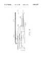
- FIG. 1is a perspective view of a two-tier embodiment of a prefabricated ,semiconductor die carrier in accordance with the present invention.
- FIG. 2is a perspective view of an SMT lead with an L-shaped foot portion configured in accordance with the present invention and positioned on a bonding pad of a multi-layer conductor such as a PCB.
- FIG. 3is a perspective view of a three-tier embodiment of a prefabricated semiconductor die carrier in accordance with the present invention.
- FIG. 4is a partial side view of a semiconductor die carrier including a cap, cavity-up configuration.
- FIG. 5is a partial side view of a semiconductor die carrier having a cavity-down configuration.
- FIG. 6is a partial side view of a semiconductor die carrier having a die indentation configuration and including a cap.
- FIG. 7is a partial side view of a semiconductor die carrier having a same or similar level configuration and including a cap.
- FIG. 8is a partial side view of a semiconductor die carrier having a platform configuration and including a cap.
- FIG. 9is a partial perspective view of a four-tier embodiment of a prefabricated semiconductor die carrier in accordance with the present invention.
- FIG. 10is a perspective view of a multi-die configuration of a prefabricated semiconductor die carrier in accordance with the present invention.
- FIG. 11is a partial side view of a semiconductor die carrier incorporating a voltage plane around the periphery of the semiconductor die.
- FIGS. 12 and 13are partial top and side views, respectively, of a semiconductor die carrier including an internal capacitor.
- FIG. 14is a partial perspective view of a semiconductor die carrier comprising an external capacitor located at ends of the rows of leads on one or more sides of the die carrier.
- FIG. 15is a partial perspective view of a semiconductor die carrier including an external capacitor comprising capacitive epoxy secured between adjacent ones of the leads on one or more sides of the die carrier.
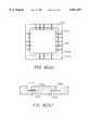
- FIG. 16is a partial top view of a footprint for a plurality of rows of leads showing multiple ground leads surrounding a high frequency signal lead.
- FIG. 17depicts a pair of flowcharts comparing a conventional manufacturing method with a method in accordance with the present invention performed in order to manufacture, transport, and mount a prefabricated semiconductor die carrier.
- a prefabricated semiconductor die carrier in accordance with the present inventionhas multiple rows of electrically conductive leads arranged at vertically spaced multiple levels around the periphery of the carrier, an internal voltage and/or ground plane, and/or at least one high frequency capacitor.
- Each of the leadsis manufactured and assembled into the semiconductor die carrier prior to the die attach step as an individually manufactured lead, rather than as a sub-element of a lead frame, to facilitate the multiple-row, multiple-level structure.
- the leads of the semiconductor die carrierextend into the die carrier through the side walls of the die carrier, forming a series of vertically spaced rows of multiple leads around the semiconductor die.
- the portions of the leads extending through the side wallshave wire bond terminals formed thereon.
- a wire bond insulatormay be used to separate the rows of leads.
- the semiconductor diecan be mounted within the carrier with the peripheral pads of the die facing up and away from the PCB, in a cavity-up configuration, or with the peripheral pads of the die facing down toward the PCB, in a flip-chip or cavity-down configuration.
- Encapsulation for the semiconductor die carrier of the present inventionis performed by filling the die cavity with an epoxy, a liquid crystal polymer such as HYSOL (a trademark of Dexter) or similar or other high-temperature material.
- the semiconductor die carriermay be capped with a plastic component or thermally conductive cap that serves as a heat sink.
- the semiconductor die carrier of the present inventionprovides a package having a reduced size as compared to known semiconductor packages, yet increases the number of interconnects available for the designer and user.
- the die carriermay be configured to be pluggable, compatible with the PTH technology, or compatible with the SMT methodology.
- the semiconductor die carrieris prefabricated and tested prior to introduction of the semiconductor die to the carrier, thereby increasing finished product yields and reducing total unit cost.
- the configuration of the die carrierallows the semiconductor die to be bonded from multiple rows of pads on the die to multiple levels of vertically spaced rows of leads while maintaining a very low profile for the die carrier.
- the semiconductor die carrierincludes a semiconductor die 101; an insulating substrate 102, having a floor 102a and a plurality of side walls 102b; a plurality of leads 103, including lower leads 103a and upper leads 103b; a plurality of bonding pads 104 formed on the semiconductor die; a plurality of bonding terminals 105 formed on the leads 103, respectively; and a plurality of bonding wires 106 each connecting at least one of the bonding pads 104 of the die to a corresponding one of the bonding terminals 105 formed on the leads.
- the insulating substrate 102 of the semiconductor die carrieris made of a liquid crystal polymer or material having properties the same or similar to a liquid crystal polymer.
- the liquid crystal polymer for the insulating substrate 102is VECTRA (trademark), which has a coefficient of thermal expansion that is approximately the same as or similar to the coefficient of thermal expansion for silicon.
- the insulating substrate 102may be formed in a molding process carried out prior to inserting the leads 103 into the side walls 102b of substrate, and prior to mounting the die 101 onto the floor 102a of the substrate.
- a series of lead holes or passages 107are molded within the side walls 102b of the substrate, each of the passages for receiving a corresponding one of the leads 103, and a series of ledges 108 are formed inside the side walls of the substrate around the periphery where the die is to be placed.
- the ledges 108serve to support the leads 103 (during the wire bonding procedure, for example).
- the lead passages and/or ledgescould be added after molding by, for example, removing material of the substrate to form the lead passages and/or by applying insulative material (using an adhesive or epoxy, for example) to form the ledges.
- the lower leads 103a and upper leads 103bare aligned in a straight line with respect to one another rather than staggered. In other words, for each upper lead 103b, a corresponding lower lead 103a is positioned directly beneath that upper lead. While not shown in FIG. 1, the lower leads 103a and upper leads 103b could be staggered with respect to one another. In a staggered configuration, none of the lower leads 103a would be beneath any of the upper leads 103b. Instead, progressing along a given one of the side walls 102b, every other lead would be a lower lead 103a or an upper lead 103b.
- each of the leads 103includes a bonding extension section 1031 having a bonding terminal 105 formed on an end portion thereof; a stabilizing section 1032; and an external lead section 1033.
- Each lead 103may be formed of beryllium copper, phosphor bronze, brass, a copper alloy, tin, gold, palladium, or any other suitable metal or conductive material, and the bonding terminal 105 may be a gold-plated pad or pad formed of another suitable conductive material.
- the bonding extension section 1031is a relatively long and narrow portion of the lead 103 which protrudes toward the interior of the semiconductor die carrier from the inner surface of a corresponding one of the side walls 102b.
- the bonding terminal 105may be, for example, a bonding pad to which a bonding wire 106 for attachment to a corresponding bonding pad 104 on the die 101 can be connected.
- the stabilizing section 1032 of each lead 103is the portion of the lead that is anchored within a side wall 102b of the substrate 102.
- the stabilizing sectionhas a larger cross-sectional area than that of the bonding extension section 1031 and may also have a larger cross-sectional area than that of the external lead section 1033.
- the thick stabilizing sectionretains the lead and prevents forces exerted on the external lead section from transferring to the bonds associated with bonding wire 106.
- the external lead section 1033includes a horizontally-extending section 1033a, a corner section 1033b, a vertically-extending section 1033c, and a foot section 1033d.
- the configuration and length of the horizontally-extending and vertically-extending sections for each individual lead 103are selected based on design requirements and, in particular, based on whether that lead will be used as a lower lead 103a or an upper lead 103b.
- a two-row semiconductor die carrier in accordance with the present inventionmay have, for example, a height of 2.0 mm, a width of 17.9 mm, and a lead row length of 8.7 mm.
- the semiconductor die carrier of the present inventioncan be manufactured to be approximately 64% smaller than conventional 128 pin QFPs, and at the same time provides 16 extra leads.
- a lead 103 in accordance with the present inventionmay have a bonding extension section 1031 that is 1.5 mm in length; a stabilizing section 1032 that is 1.0 mm in length, and an external lead section 1033 having a vertically-extending section 1033c that varies in length depending whether the lead is an upper lead or a lower lead.
- the foot section 1033d of a lead 103 configured for mounting in accordance with SMTcan have a cross-section of 0.2 ⁇ 0.4 mm, for example, for mounting on an SMT solder joint 109 of a PCB having an exemplary cross-section of 0.4 ⁇ 0.6 mm.
- FIG. 3A perspective view of another embodiment of a prefabricated semiconductor die carrier in accordance with the present invention is shown in FIG. 3.
- the embodiment of FIG. 3essentially corresponds to the embodiment shown in FIG. 1, except that three vertically spaced rows of multiple leads 103a, 103b, and 103c are used instead of two of such rows.
- Such a configurationenhances the interconnect capabilities of the semiconductor die carrier.
- ledges 108might be applicable to the three-row semiconductor die carrier in accordance with the present invention.
- the semiconductor die carrier of FIG. 3may be manufactured in the same manner that the carrier shown in FIG. 1 is manufactured. Exemplary dimensions for the embodiment of FIG. 3 are a height of 2.7 mm; a width of 21.5 mm; and a lead row length of 11.8 mm. In this configuration, the semiconductor die carrier of FIG. 3 can be configured to provide 208 leads using approximately half of the area (for example, board area) of that required by conventional QFP technology.
- FIG. 4A partial side view of the embodiment of FIG. 3 is shown in FIG. 4.
- the illustration of FIG. 4shows features of the semiconductor die carrier including a die bond adhesive 111 for mounting the die 101 on the floor 102a; bonding wires 106 which, in each of the embodiments of the present invention, may be dimensioned to have a wire length of less than 1.0 to 2.5 mm, for example; a cavity filler 112 used to fill the cavity defined by the floor 102a and side walls 102b of the carrier during the encapsulation process; and a sealing cap 113, made of plastic or other thermally-conductive material such as metal or VECTRA (trademark), and capable of functioning as a heat sink, for providing a cover for the semiconductor die carrier.
- a die bond adhesive 111for mounting the die 101 on the floor 102a
- bonding wires 106which, in each of the embodiments of the present invention, may be dimensioned to have a wire length of less than 1.0 to 2.5 mm, for example
- FIGS. 5-8show various configurations relating to the placement of the semiconductor die 101 within the semiconductor die carrier. Although FIGS. 5-8 depict an embodiment having three-row configuration, it should be noted that the die placement configurations illustrated in these figures are also applicable to the other embodiments of the present invention, including the one-row and two-row embodiments discussed above and the four-row embodiments discussed below.
- FIG. 4corresponds to a cavity-up configuration, in which the semiconductor die is mounted within the carrier with the peripheral pads of the die facing up and away from the PCB or other mounting surface
- FIG. 5corresponds to a cavity-down or flip-chip configuration, in which the peripheral pads of the die face down toward the PCB or other interface surface.
- the die 101is mounted on a heat sink cap 114, preferably formed of a thermally conductive material, and then wire bonding, encapsulation, and sealing using a sealing cap 113, preferably formed of VECTRA (trademark), take place.
- the heat sink cap 114can be an integrally molded component of the substrate 102, or attached to the substrate 102 after molding of the substrate is completed.
- FIG. 6shows that the semiconductor die 101 may be embedded or placed into an indentation, similar to the size of the semiconductor die, formed in the floor 102a for receipt of the die.
- the top surface of the dieis located below the bonding extension sections 1031 of the lower leads 103a.
- FIG. 7shows the placement of the semiconductor die 101 on top of a flat floor 102a.
- the top surface of the semiconductor die 101is the same level or similar in height to the height of the bonding extension sections 1031 of the lower leads 103a.
- FIG. 8shows the placement of the semiconductor die 101 on a raised platform 115, similar to the size of the die, formed in the interior of the semiconductor die carrier.
- the raised platform 115may be an integrally molded component of the substrate 102, or attached to the substrate 102 after molding of the substrate is completed.
- the semiconductor die 101may be mounted using an adhesive material, epoxy, or the like.
- FIG. 9A partial view of another embodiment of a preferred semiconductor die carrier in accordance with the present invention is shown in FIG. 9.
- the embodiment of FIG. 9essentially corresponds to the embodiments shown in FIGS. 1 and 3, for example, except that four vertically spaced rows of multiple leads 103a, 103b, 103c, and 103d are used instead of two or three of such rows. Such a configuration further enhances the interconnect capabilities of the semiconductor die carrier.
- FIG. 9illustrates that, in all the embodiments of the present invention, the stabilizing section 1032 of each lead 103 may overlap or extend beyond the inner surface of its corresponding side wall 102b, if desired. Alternatively, in all of the embodiments of the present invention, a stop could be used to prevent over-insertion of the leads.
- the semiconductor die carrier of FIG. 9is manufactured in the same manner that the die carriers shown in FIGS. 1 and 3 are manufactured. Exemplary dimensions for the embodiment of FIG. 9 are a height of 3.4 mm; a width of approximately 28.0 mm; and a lead row length of 16.2 mm. In this configuration, the semiconductor die carrier of FIG. 9 can be manufactured to be approximately 57% smaller than conventional 304-pin QFPs.
- FIG. 10is a perspective view of another aspect of the present invention that is applicable to all of the previously-discussed embodiments.
- a plurality (e.g., four) of semiconductor dies 101may be incorporated within a prefabricated semiconductor die carrier in accordance with the present invention, thus allowing an even more efficient usage of materials and board space.
- a multi-layer ceramic component 122having a plurality of levels of electrically conductive material therein, is glued or otherwise adhered to the floor 102a, and the plurality of semiconductor dies 101 are glued or otherwise adhered to the multi-layer ceramic component.
- the diesmay or may not be electrically connected to the multi-layer ceramic component using C4, wire bond, TAB, or other bonding technologies.
- conductive lands on the bottom surface of the diesare used to provide electrical interconnection between the dies and the ceramic component 122.
- bonding wires(now shown) connected at one end to the bonding pads 104 and at the other end to the ceramic component 122 are used to provide electrical interconnection between the dies and the ceramic component.
- the leads 103are either soldered to the ceramic component 122, or electrically connected to the ceramic component using bonding wires (not shown).
- bonding wires(not shown)
- FIG. 10shows the incorporation of four semiconductor dies within a single prefabricated semiconductor die carrier in accordance with the present invention, either more or less dies per semiconductor die carrier are contemplated. As stated previously, the incorporation of a plurality of semiconductor dies within a single die carrier allows more effective usage of materials and board space.
- the multi-layer ceramic component 122may be configured to include one or more power planes and/or one or more ground planes.
- each power plane of the multi-layer ceramic component 122could be connected to a bonding wire coupled to at least one of the leads 103 connected to an external power source (e.g., +5 V or -5 V), and each ground plane of the ceramic component could be connected to a bonding wire coupled to at least one of the leads connected to an external ground (0 V).
- each die 101 secured to the multi-layer ceramic component 122would have its periphery surrounded by at least one power plane and/or at least one ground plane. Positioning the power and ground supplies of the PCB level within the insulative module of the semiconductor die carrier results in many advantages, including the reduction of signal degradation and the facilitation of design and manufacturing.
- FIG. 11is a partial side view of a semiconductor die carrier in accordance with the invention including a stick-on adhesive copper foil 116 acting as a V+ bus (or alternatively, a V- bus) all around the periphery of semiconductor die 101. As with the embodiment of FIG. 10, this pulls the power supply at the PCB level inside the semiconductor die carrier module.
- power plane 116could be replaced with a copper foil acting as a ground plane or, alternatively, a separate ground plane surrounding the periphery of semiconductor die 101 could be used in addition to power plane 116 with the ground plane either being surrounded by or surrounding power plane 116.
- die attach plate 114 and power plane 116are preferably attached to opposite ends of a high frequency capacitor in accordance with the discussion pertaining to FIGS. 12 and 13 below.
- FIG. 12is a partial top view of a semiconductor die carrier including an internal capacitor 117 mounted at one or more (e.g., all) of the corners of the semiconductor die carrier, and FIG. 13 is a side view of the subject matter surrounded by the circle depicted in FIG. 12.
- Capacitor 117is a high frequency capacitor (0.1 to 100 ⁇ F, for example) designed to reduce performance-limiting noise problems such as delta I degradation which arise especially in connection with semiconductor die carriers that handle high frequency (50-110 ns) signals. Such a situation would occur if semiconductor die 101 were a microprocessor having an operating frequency of 300 Mhz, for example.
- capacitor 117 as depicted in FIGS. 12 and 13is represented as an internal capacitor housed within the semiconductor die carrier, alternatively, capacitor 117 could be an external capacitor secured externally with respect to the semiconductor die carrier. As an example, one of the capacitors 117 could be located on an external surface of the semiconductor die carrier at each of its four corners.
- FIG. 13depicts a preferred embodiment of the present invention (leads and die-to-lead bonding wires not shown) wherein power plane 116 (at +V or -V, for example) on grounded die attach plate 114 surrounds the periphery of semiconductor die 101 with one end of capacitor 117 connected to the grounded die attach plate and with the other end of capacitor 117 connected to the power plane.
- Such connectionsare achieved, respectively, using a first bonding wire 118a and a second bonding wire 118b.
- each of the connections depicted in and relating to FIG. 13is also applicable to the embodiment depicted in FIG. 12.
- FIG. 14shows an alternative embodiment of the invention wherein a high frequency capacitor (comprising a block of ceramic, for example) is mounted at each end (or, alternatively, at just one end) of each of the rows of leads 103 on the external surface of the semiconductor die carrier. More particularly, as depicted in FIG. 14, a capacitor 119 is secured to the outermost surface of each of the outermost leads of rows 103a and 103c on each of the sides of the die carrier (or, alternatively, on just one, two, or three sides of the die carrier), providing a total of up to eight such capacitors (i.e., up to two capacitors per side).
- a capacitor 119is secured to the outermost surface of each of the outermost leads of rows 103a and 103c on each of the sides of the die carrier (or, alternatively, on just one, two, or three sides of the die carrier), providing a total of up to eight such capacitors (i.e., up to two capacitors per side).
- each capacitor 119is soldered, epoxied, or otherwise adhered to insulative side wall 102b and/or the outermost leads in each of rows 103a and 103c, as depicted in FIG. 14.
- the purpose of capacitor 119 of FIG. 14is the same as that of capacitor 117 of FIGS. 12 and 13, namely, to reduce noise and delta I degradation and to facilitate the transmission of high frequency signals to and from semiconductor die 101 via the leads 103.
- capacitor 119 of FIG. 14may be secured to the leads of the semiconductor die carrier using epoxy, adhesive, solder, or the like.
- the present inventioncontemplates replacing one or more (e.g., all) of capacitors 119 with some other externally mounted device such as a temperature sensor or crystal.
- capacitors 119 of FIG. 14provides a number of important advantages. First and foremost, the placement of capacitors on external rather than internal surfaces of the semiconductor die carrier prevents disruption of valuable interior die carrier space, thereby providing substantially more room within the die carrier for the inclusion of additional components. Moreover, external capacitors are not constrained by the dimensions of the internal cavity of the die carrier and, therefore larger capacitors can be used when die carrier design needs so dictate. Furthermore, the external placement of capacitors 119 makes them very accessible and, therefore, more suitable for testing, replacement, and upgrades.
- FIG. 15is a partial perspective view of another alternative embodiment of the semiconductor die carrier of the present invention.
- each leadis separated from one of its adjacent leads by a first distance (0.8 mm, for example) and from the other of its adjacent leads by a second distance (0.5 mm, for example), the first distance being greater than the second distance.
- a capacitor 120may be placed between one or more (e.g., all) of the adjacent leads within one or more of the rows of leads which are separated by the lesser distance (as shown in FIG.
- each capacitor 120comprises a dielectric or capacitive epoxy including an epoxic carrier having a viscous quality and related curing properties, or a ceramic material, sandwiched by the leads on either side. It is envisioned that capacitor 120 may not only enhance the electrical properties of the semiconductor die carrier, but also may enhance its mechanical properties by providing physical support to the leads with which it is in contact, thereby stiffening the leads to prevent inadvertent bending and the like. In the embodiment of FIG. 15, it is envisioned that all of the rows or, alternatively, only some of the rows (e.g., rows 103a and 103c) will be provided with capacitors 120.
- each high frequency signal lead Sis surrounded by a plurality of ground leads G, which enhances the integrity of any high frequency signal travelling on high frequency signal lead S due to the coaxial cable-type effect resulting from the surrounding of the high frequency lead S with ground leads G.
- prefabricated semiconductor die carrierhaving one row of multiple leads or two, three, or four vertically spaced rows of multiple leads. While not shown in the accompanying drawings, in accordance with the present invention, prefabricated semiconductor die carriers having five or more vertically spaced rows of multiple leads are also contemplated. Such prefabricated semiconductor die carriers are considered to be within the spirit and scope of the present invention. Moreover, although the power/ground plane and high frequency capacitor embodiments have been depicted herein in connection with die carriers incorporating three rows of leads, it should be noted that such embodiments are also applicable to semiconductor die carriers having one row of multiple leads or two, four, or five or more vertically spaced rows of multiple leads.
- FIG. 17includes two flowcharts.
- the flowchart at the leftillustrates steps performed in the manufacturing of a conventional molded plastic semiconductor package.
- the flowchart at the rightillustrates steps performed in a manufacturing process for producing a prefabricated semiconductor carrier in accordance with the present invention.
- the present inventionentails fewer steps following the die bond procedure as compared to conventional manufacturing processes. Most notably, the molding, mold cure, deflash, shear, lead electroplate, lead trim and form, and solder dip steps of the conventional manufacturing process are completely absent from the manufacturing process of the present invention following die bonding. The result is that the costly yield losses associated with the conventional process are completely avoided by the manufacturing process of the present invention.
- the substrate 102including the floor 102a and side walls 102b and, if desired, lead passages 107 and ledges 108, are integrally formed using a molding process.
- the lead passages and/or ledgescould be added after molding by, for example, removing material of the substrate to form the passages and/or by applying insulative material (using an adhesive or epoxy, for example) to form the ledges.
- the floor 102a and side walls 102bcould be molded separately, and then fastened together using an epoxy or other adhesive.
- VECTRAtrademark
- the use of VECTRA (trademark) as the material for the substrateallows the parts of the semiconductor die carrier to be molded and assembled with a high degree of accuracy.
- the substratecould be formed around the leads in an insert molding process.
- the leads 103are formed.
- the lead formation step S2entails punching or stamping out individual leads from strips or drawn wire using, for example, a die. Applicants have found that by individually manufacturing each lead 103, rather than using a lead frame to manufacture such leads, manufacturing costs are reduced and, at the same time, yield is increased.
- the aforementioned lead-manufacturing methodsallow for selective plating and automated insertion.
- the leads for stampingcan either be loose, on a bandolier carrier, or on a strip since the asymmetrical shape lends itself to consistent orientation in automated assembly equipment.
- the different length external lead sectionsassist with orientation and vibratory bowl feeding during automated assembly.
- the present inventionis compatible with both stitching and gang-insertion assembly equipment.
- the insulative componentshave been designed to facilitate automatic and robotic insertion onto PCBs or in termination of wire to connector.
- Step S3 of FIG. 17involves inserting the leads 103 into the side walls 102b of the substrate 102.
- the leadsmay be inserted into the side walls before they are fastened to one another or to the floor.
- Each of the leads 103is inserted into a corresponding one of the lead passages 107 in the side walls 102b.
- the dimensions of the leads 103 and lead passages 107are such that each lead fits tightly within it corresponding lead passage 107.
- each lead 103can be further fastened within its corresponding lead passage 107 and/or onto a corresponding ledge 108 using an epoxy or other adhesive material.
- Insert moldingis applicable to all embodiments of the present invention.
- step S4elements such as power plane 116 and/or high frequency capacitors 117, 119, or 120 may be soldered or otherwise adhered to the semiconductor die package. If such elements are added before step S4, which is preferable, then they may undergo electrical and mechanical testing along with the remaining components of the semiconductor die carrier during the course of carrying out step S4. In other words, capacitor and inductance tests can be performed with respect to such elements before the initial shipping and die placement.
- step S4mechanical testing is performed to ensure that the leads 103 are securely fastened within the substrate 102; to ensure that coplanarity of the leads 103 falls within an acceptable range; to ensure that each lead is aligned properly within its respective lead passage; and the like. Also, electrical testing is performed to ensure that signals can be transmitted properly through the leads of the carrier to the exterior of the carrier, and vice versa; and to ensure that none of the leads are shorted or would be likely to short during subsequent stages of the manufacture and usage of the semiconductor die carrier.
- step S5the substrate 102 having leads 103 disposed therein is packaged and then shipped to the place where a semiconductor die, manufactured in step SG, will be bonded to the substrate.
- Step S7 of FIG. 17involves attaching the semiconductor die 101 to floor 102a or another support surface (for example, a raised platform 115) within the semiconductor die carrier.
- the attachmentmay be carried out using an adhesive, an epoxy or the like.
- Step S8entails a bonding procedure wherein a bonding wire 106 is connected between components of a pair including a bonding pad 104 on the die 101 and a bonding terminal 105 on one of the leads 103.
- the bonding wiresallow electrical connection between the die 101 and the various leads 103.
- step S9further electrical tests may be performed to provide additional assurance that an acceptable product is being manufactured.
- step S10encapsulation is performed by filling the cavity defined by the floor 102a and the side walls 102b of the substrate 102 with epoxy, a liquid crystal polymer such as VECTRA (trademark), or other high-temperature material. Then the semiconductor die carrier may capped with a plastic component or thermally-conductive cap that may serve as a heat sink, and thereafter sealed, although use of a cap is optional. It should be noted that when a cap is used, the aforementioned encapsulation step becomes optional. The heat sink and/or high-temperature material which may be used for encapsulation and sealing facilitate the heat dissipation capabilities of the semiconductor die carrier.
- step S11further mechanical and electrical quality control testing may be performed to increase the likelihood that the semiconductor die carrier will function as expected.
- the completed semiconductor die carrieris packaged and shipped to the customer.
- the semiconductor die carrieris packaged and shipped to the customer using the same transportation package it was received in.
- Step S13relates to the mounting of the finished semiconductor die carrier on or within an interface surface such as a PCB surface.
- an interface surfacesuch as a PCB surface.
- either PTH technology or SMT methodologymay be used to accomplish PCB interfacing or, alternatively, the carrier may be plugged into a pluggable socket mounted on a PCB or other interface device.
- the configurations of the footprints of the semiconductor die carrierfacilitate the routing of traces on the PCB or other interface surface onto or within which the semiconductor die carrier is being mounted. Further mechanical and electrical testing can be performed after the mounting process is completed.
- the semiconductor die carrier of the present inventionbegins as a pre-formed platform into which the die is inserted. Encapsulation is then accomplished by capping and sealing the platform after it has been tested. This results in the elimination of the entire molding, bending, and clean-up processes and the related bonding of the carrier. Because the leads of the present invention are pre-formed and inserted into the plastic platform, they are undisturbed by additional procedures conventionally performed after the die is introduced into the semiconductor package. In the conventional process, the most sensitive aspects of the manufacturing process, encapsulating the die and electroplating and forming the leads, are performed after the die and the semiconductor package have been mated.
- the semiconductor die carrier of the present inventioncould be delivered to the die attach area completely tested for plating, mechanical integrity, and dimensional characteristics, and the die need only be inserted into packages meeting acceptable quality standards. The elimination of the intermediate processes also reduces labor costs.
- the semiconductor die carrier of the present inventioncan be configured with a precise number of leads easier than current designs due to the programmable nature of its assembly.
- a designercan specify varied numbers of leads or changes in package size, without the need to design and manufacture new lead frame configurations.
- both the number of leads on a side of a package, and the number of rows of leadscan be varied simply by producing a new mold for the prefabricated platform and reprogramming the lead insertion equipment to vary the number of leads or lead configuration.
- the present inventionprovides many advantages over conventional packaging technology. Such advantages include enhanced noise reduction and the provision of a semiconductor die carrier handling high frequency signals in the absence of signal degradation, occupying reduced amounts of area, and being capable of meeting the needs of existing and contemplated semiconductor and computer technology.
- the advantages provided by the present invention over conventional packaging technologyillustrate that the present invention, unlike conventional packaging technology, is capable of keeping pace with the rapid advances that are currently taking place in the semiconductor and computer technologies.
Landscapes
- Engineering & Computer Science (AREA)
- Computer Hardware Design (AREA)
- Microelectronics & Electronic Packaging (AREA)
- Power Engineering (AREA)
- Physics & Mathematics (AREA)
- Condensed Matter Physics & Semiconductors (AREA)
- General Physics & Mathematics (AREA)
- Lead Frames For Integrated Circuits (AREA)
Abstract
Description
Claims (10)
Priority Applications (1)
| Application Number | Priority Date | Filing Date | Title |
|---|---|---|---|
| US08/902,032US5821457A (en) | 1994-03-11 | 1997-07-29 | Semiconductor die carrier having a dielectric epoxy between adjacent leads |
Applications Claiming Priority (3)
| Application Number | Priority Date | Filing Date | Title |
|---|---|---|---|
| US08/208,586US6339191B1 (en) | 1994-03-11 | 1994-03-11 | Prefabricated semiconductor chip carrier |
| US48710095A | 1995-06-07 | 1995-06-07 | |
| US08/902,032US5821457A (en) | 1994-03-11 | 1997-07-29 | Semiconductor die carrier having a dielectric epoxy between adjacent leads |
Related Parent Applications (1)
| Application Number | Title | Priority Date | Filing Date |
|---|---|---|---|
| US48710095AContinuation | 1994-03-11 | 1995-06-07 |
Publications (1)
| Publication Number | Publication Date |
|---|---|
| US5821457Atrue US5821457A (en) | 1998-10-13 |
Family
ID=26903313
Family Applications (1)
| Application Number | Title | Priority Date | Filing Date |
|---|---|---|---|
| US08/902,032Expired - Fee RelatedUS5821457A (en) | 1994-03-11 | 1997-07-29 | Semiconductor die carrier having a dielectric epoxy between adjacent leads |
Country Status (1)
| Country | Link |
|---|---|
| US (1) | US5821457A (en) |
Cited By (127)
| Publication number | Priority date | Publication date | Assignee | Title |
|---|---|---|---|---|
| US5936492A (en)* | 1996-04-24 | 1999-08-10 | Honda Giken Kogyo Kabushiki Kaisha | Ribbon, bonding wire and microwave circuit package |
| US6047467A (en)* | 1995-10-12 | 2000-04-11 | Vlsi Technology, Inc. | Printed circuit board layout to minimize the clock delay caused by mismatch in length of metal lines and enhance the thermal performance of microelectronics packages via conduction through the package leads |
| US6184579B1 (en)* | 1998-07-07 | 2001-02-06 | R-Amtech International, Inc. | Double-sided electronic device |
| US6266246B1 (en)* | 1997-11-14 | 2001-07-24 | Silicon Bandwidth, Inc. | Multi-chip module having interconnect dies |
| US6434726B1 (en) | 1999-06-29 | 2002-08-13 | Lucent Technologies Inc. | System and method of transmission using coplanar bond wires |
| US6489869B2 (en)* | 2000-03-08 | 2002-12-03 | Juergen Breitlow-Hertzfeldt | Electrical component and process for the manufacture thereof |
| US20030147227A1 (en)* | 2002-02-05 | 2003-08-07 | International Business Machines Corporation | Multi-layered interconnect structure using liquid crystalline polymer dielectric |
| US6730544B1 (en)* | 1999-12-20 | 2004-05-04 | Amkor Technology, Inc. | Stackable semiconductor package and method for manufacturing same |
| US6750545B1 (en) | 2003-02-28 | 2004-06-15 | Amkor Technology, Inc. | Semiconductor package capable of die stacking |
| US6777789B1 (en) | 2001-03-20 | 2004-08-17 | Amkor Technology, Inc. | Mounting for a package containing a chip |
| US6794740B1 (en) | 2003-03-13 | 2004-09-21 | Amkor Technology, Inc. | Leadframe package for semiconductor devices |
| US6798047B1 (en) | 2002-12-26 | 2004-09-28 | Amkor Technology, Inc. | Pre-molded leadframe |
| US6825551B1 (en)* | 1999-09-02 | 2004-11-30 | Stmicroelectronics S.A. | Method for packaging a semiconductor chip containing sensors and resulting package |
| US6846704B2 (en) | 2001-03-27 | 2005-01-25 | Amkor Technology, Inc. | Semiconductor package and method for manufacturing the same |
| US6873041B1 (en) | 2001-11-07 | 2005-03-29 | Amkor Technology, Inc. | Power semiconductor package with strap |
| US6876068B1 (en) | 2002-09-09 | 2005-04-05 | Amkor Technology, Inc | Semiconductor package with increased number of input and output pins |
| US6879034B1 (en) | 2003-05-01 | 2005-04-12 | Amkor Technology, Inc. | Semiconductor package including low temperature co-fired ceramic substrate |
| US20050093152A1 (en)* | 2003-10-10 | 2005-05-05 | Fjelstad Joseph C. | Multi-surface contact IC packaging structures and assemblies |
| US20050093127A1 (en)* | 2003-09-24 | 2005-05-05 | Fjelstad Joseph C. | Multi-surface IC packaging structures and methods for their manufacture |
| US6893900B1 (en) | 1998-06-24 | 2005-05-17 | Amkor Technology, Inc. | Method of making an integrated circuit package |
| US20050103522A1 (en)* | 2003-11-13 | 2005-05-19 | Grundy Kevin P. | Stair step printed circuit board structures for high speed signal transmissions |
| US6897550B1 (en) | 2003-06-11 | 2005-05-24 | Amkor Technology, Inc. | Fully-molded leadframe stand-off feature |
| US6919620B1 (en) | 2002-09-17 | 2005-07-19 | Amkor Technology, Inc. | Compact flash memory card with clamshell leadframe |
| US6921967B2 (en) | 2003-09-24 | 2005-07-26 | Amkor Technology, Inc. | Reinforced die pad support structure |
| US6927483B1 (en) | 2003-03-07 | 2005-08-09 | Amkor Technology, Inc. | Semiconductor package exhibiting efficient lead placement |
| US20050189640A1 (en)* | 2003-11-13 | 2005-09-01 | Grundy Kevin P. | Interconnect system without through-holes |
| US6953988B2 (en) | 2000-03-25 | 2005-10-11 | Amkor Technology, Inc. | Semiconductor package |
| US6956282B1 (en)* | 1997-11-05 | 2005-10-18 | Texas Instruments Incorporated | Stabilizer/spacer for semiconductor device |
| US20050239300A1 (en)* | 2004-02-09 | 2005-10-27 | Gary Yasumura | High speed, direct path, stair-step, electronic connectors with improved signal integrity characteristics and methods for their manufacture |
| US6965157B1 (en) | 1999-11-09 | 2005-11-15 | Amkor Technology, Inc. | Semiconductor package with exposed die pad and body-locking leadframe |
| US6965159B1 (en) | 2001-09-19 | 2005-11-15 | Amkor Technology, Inc. | Reinforced lead-frame assembly for interconnecting circuits within a circuit module |
| US6967395B1 (en) | 2001-03-20 | 2005-11-22 | Amkor Technology, Inc. | Mounting for a package containing a chip |
| US20050285265A1 (en)* | 2000-11-01 | 2005-12-29 | Campbell Scott P | Frame scale package using contact lines through the elements |
| US7001799B1 (en) | 2003-03-13 | 2006-02-21 | Amkor Technology, Inc. | Method of making a leadframe for semiconductor devices |
| US7005326B1 (en) | 1998-06-24 | 2006-02-28 | Amkor Technology, Inc. | Method of making an integrated circuit package |
| US7008825B1 (en) | 2003-05-27 | 2006-03-07 | Amkor Technology, Inc. | Leadframe strip having enhanced testability |
| US7030474B1 (en) | 1998-06-24 | 2006-04-18 | Amkor Technology, Inc. | Plastic integrated circuit package and method and leadframe for making the package |
| US7045396B2 (en) | 1999-12-16 | 2006-05-16 | Amkor Technology, Inc. | Stackable semiconductor package and method for manufacturing same |
| US7045883B1 (en) | 2001-04-04 | 2006-05-16 | Amkor Technology, Inc. | Thermally enhanced chip scale lead on chip semiconductor package and method of making same |
| US7045882B2 (en) | 2000-12-29 | 2006-05-16 | Amkor Technology, Inc. | Semiconductor package including flip chip |
| US7057280B2 (en) | 1998-11-20 | 2006-06-06 | Amkor Technology, Inc. | Leadframe having lead locks to secure leads to encapsulant |
| US7057268B1 (en) | 2004-01-27 | 2006-06-06 | Amkor Technology, Inc. | Cavity case with clip/plug for use on multi-media card |
| US7064009B1 (en) | 2001-04-04 | 2006-06-20 | Amkor Technology, Inc. | Thermally enhanced chip scale lead on chip semiconductor package and method of making same |
| US7067908B2 (en) | 1999-10-15 | 2006-06-27 | Amkor Technology, Inc. | Semiconductor package having improved adhesiveness and ground bonding |
| US7071541B1 (en) | 1998-06-24 | 2006-07-04 | Amkor Technology, Inc. | Plastic integrated circuit package and method and leadframe for making the package |
| US7091594B1 (en) | 2004-01-28 | 2006-08-15 | Amkor Technology, Inc. | Leadframe type semiconductor package having reduced inductance and its manufacturing method |
| US7095103B1 (en) | 2003-05-01 | 2006-08-22 | Amkor Technology, Inc. | Leadframe based memory card |
| US7102208B1 (en) | 1999-10-15 | 2006-09-05 | Amkor Technology, Inc. | Leadframe and semiconductor package with improved solder joint strength |
| US7112474B1 (en) | 1998-06-24 | 2006-09-26 | Amkor Technology, Inc. | Method of making an integrated circuit package |
| US7115445B2 (en) | 1999-10-15 | 2006-10-03 | Amkor Technology, Inc. | Semiconductor package having reduced thickness |
| US7138707B1 (en) | 2003-10-21 | 2006-11-21 | Amkor Technology, Inc. | Semiconductor package including leads and conductive posts for providing increased functionality |
| US7170150B2 (en) | 2001-03-27 | 2007-01-30 | Amkor Technology, Inc. | Lead frame for semiconductor package |
| US7183630B1 (en) | 2002-04-15 | 2007-02-27 | Amkor Technology, Inc. | Lead frame with plated end leads |
| US7190062B1 (en) | 2004-06-15 | 2007-03-13 | Amkor Technology, Inc. | Embedded leadframe semiconductor package |
| US7192807B1 (en) | 2002-11-08 | 2007-03-20 | Amkor Technology, Inc. | Wafer level package and fabrication method |
| US7202554B1 (en) | 2004-08-19 | 2007-04-10 | Amkor Technology, Inc. | Semiconductor package and its manufacturing method |
| US7211879B1 (en) | 2003-11-12 | 2007-05-01 | Amkor Technology, Inc. | Semiconductor package with chamfered corners and method of manufacturing the same |
| US7214326B1 (en) | 2003-11-07 | 2007-05-08 | Amkor Technology, Inc. | Increased capacity leadframe and semiconductor package using the same |
| US7217991B1 (en) | 2004-10-22 | 2007-05-15 | Amkor Technology, Inc. | Fan-in leadframe semiconductor package |
| US7245007B1 (en) | 2003-09-18 | 2007-07-17 | Amkor Technology, Inc. | Exposed lead interposer leadframe package |
| US7253503B1 (en) | 1999-11-05 | 2007-08-07 | Amkor Technology, Inc. | Integrated circuit device packages and substrates for making the packages |
| US20070205496A1 (en)* | 2004-06-25 | 2007-09-06 | Tessera, Inc. | Microelectronic packages and methods therefor |
| US7332375B1 (en) | 1998-06-24 | 2008-02-19 | Amkor Technology, Inc. | Method of making an integrated circuit package |
| CN100378970C (en)* | 2005-04-22 | 2008-04-02 | 北京中星微电子有限公司 | Multipurpose load plate |
| US7361533B1 (en) | 2002-11-08 | 2008-04-22 | Amkor Technology, Inc. | Stacked embedded leadframe |
| US20080150101A1 (en)* | 2006-12-20 | 2008-06-26 | Tessera, Inc. | Microelectronic packages having improved input/output connections and methods therefor |
| US20080165257A1 (en)* | 2007-01-05 | 2008-07-10 | Micron Technology, Inc. | Configurable pixel array system and method |
| US20080278610A1 (en)* | 2007-05-11 | 2008-11-13 | Micron Technology, Inc. | Configurable pixel array system and method |
| US7485952B1 (en) | 2001-09-19 | 2009-02-03 | Amkor Technology, Inc. | Drop resistant bumpers for fully molded memory cards |
| US7507603B1 (en) | 2005-12-02 | 2009-03-24 | Amkor Technology, Inc. | Etch singulated semiconductor package |
| US7572681B1 (en) | 2005-12-08 | 2009-08-11 | Amkor Technology, Inc. | Embedded electronic component package |
| US20090200655A1 (en)* | 1994-12-29 | 2009-08-13 | Tessera, Inc. | Method of electrically connecting a microelectronic component |
| US7598598B1 (en) | 2003-02-05 | 2009-10-06 | Amkor Technology, Inc. | Offset etched corner leads for semiconductor package |
| US7687899B1 (en) | 2007-08-07 | 2010-03-30 | Amkor Technology, Inc. | Dual laminate package structure with embedded elements |
| US7687893B2 (en) | 2006-12-27 | 2010-03-30 | Amkor Technology, Inc. | Semiconductor package having leadframe with exposed anchor pads |
| US7723852B1 (en) | 2008-01-21 | 2010-05-25 | Amkor Technology, Inc. | Stacked semiconductor package and method of making same |
| US7723210B2 (en) | 2002-11-08 | 2010-05-25 | Amkor Technology, Inc. | Direct-write wafer level chip scale package |
| US7768135B1 (en) | 2008-04-17 | 2010-08-03 | Amkor Technology, Inc. | Semiconductor package with fast power-up cycle and method of making same |
| US7777351B1 (en) | 2007-10-01 | 2010-08-17 | Amkor Technology, Inc. | Thin stacked interposer package |
| US7808084B1 (en) | 2008-05-06 | 2010-10-05 | Amkor Technology, Inc. | Semiconductor package with half-etched locking features |
| US7829990B1 (en) | 2007-01-18 | 2010-11-09 | Amkor Technology, Inc. | Stackable semiconductor package including laminate interposer |
| US7847392B1 (en) | 2008-09-30 | 2010-12-07 | Amkor Technology, Inc. | Semiconductor device including leadframe with increased I/O |
| US7847386B1 (en) | 2007-11-05 | 2010-12-07 | Amkor Technology, Inc. | Reduced size stacked semiconductor package and method of making the same |
| US7875963B1 (en) | 2008-11-21 | 2011-01-25 | Amkor Technology, Inc. | Semiconductor device including leadframe having power bars and increased I/O |
| US7902660B1 (en) | 2006-05-24 | 2011-03-08 | Amkor Technology, Inc. | Substrate for semiconductor device and manufacturing method thereof |
| US7956453B1 (en) | 2008-01-16 | 2011-06-07 | Amkor Technology, Inc. | Semiconductor package with patterning layer and method of making same |
| US7960818B1 (en) | 2009-03-04 | 2011-06-14 | Amkor Technology, Inc. | Conformal shield on punch QFN semiconductor package |
| US7968998B1 (en) | 2006-06-21 | 2011-06-28 | Amkor Technology, Inc. | Side leaded, bottom exposed pad and bottom exposed lead fusion quad flat semiconductor package |
| US7977774B2 (en) | 2007-07-10 | 2011-07-12 | Amkor Technology, Inc. | Fusion quad flat semiconductor package |
| US7982297B1 (en) | 2007-03-06 | 2011-07-19 | Amkor Technology, Inc. | Stackable semiconductor package having partially exposed semiconductor die and method of fabricating the same |
| US7982298B1 (en) | 2008-12-03 | 2011-07-19 | Amkor Technology, Inc. | Package in package semiconductor device |
| US7989933B1 (en) | 2008-10-06 | 2011-08-02 | Amkor Technology, Inc. | Increased I/O leadframe and semiconductor device including same |
| US8026589B1 (en) | 2009-02-23 | 2011-09-27 | Amkor Technology, Inc. | Reduced profile stackable semiconductor package |
| US8058715B1 (en) | 2009-01-09 | 2011-11-15 | Amkor Technology, Inc. | Package in package device for RF transceiver module |
| US8067821B1 (en) | 2008-04-10 | 2011-11-29 | Amkor Technology, Inc. | Flat semiconductor package with half package molding |
| US8072050B1 (en) | 2008-11-18 | 2011-12-06 | Amkor Technology, Inc. | Semiconductor device with increased I/O leadframe including passive device |
| US8089159B1 (en) | 2007-10-03 | 2012-01-03 | Amkor Technology, Inc. | Semiconductor package with increased I/O density and method of making the same |
| US8089145B1 (en) | 2008-11-17 | 2012-01-03 | Amkor Technology, Inc. | Semiconductor device including increased capacity leadframe |
| US8125064B1 (en) | 2008-07-28 | 2012-02-28 | Amkor Technology, Inc. | Increased I/O semiconductor package and method of making same |
| US8184453B1 (en) | 2008-07-31 | 2012-05-22 | Amkor Technology, Inc. | Increased capacity semiconductor package |
| US8294276B1 (en) | 2010-05-27 | 2012-10-23 | Amkor Technology, Inc. | Semiconductor device and fabricating method thereof |
| US8318287B1 (en) | 1998-06-24 | 2012-11-27 | Amkor Technology, Inc. | Integrated circuit package and method of making the same |
| US8324511B1 (en) | 2010-04-06 | 2012-12-04 | Amkor Technology, Inc. | Through via nub reveal method and structure |
| US8390130B1 (en) | 2011-01-06 | 2013-03-05 | Amkor Technology, Inc. | Through via recessed reveal structure and method |
| US8410585B2 (en) | 2000-04-27 | 2013-04-02 | Amkor Technology, Inc. | Leadframe and semiconductor package made using the leadframe |
| US20130087898A1 (en)* | 2010-05-17 | 2013-04-11 | Stats Chippac, Ltd. | Semiconductor Device and Method of Forming Prefabricated Multi-Die Leadframe for Electrical Interconnect of Stacked Semiconductor Die |
| US8440554B1 (en) | 2010-08-02 | 2013-05-14 | Amkor Technology, Inc. | Through via connected backside embedded circuit features structure and method |
| US8487445B1 (en) | 2010-10-05 | 2013-07-16 | Amkor Technology, Inc. | Semiconductor device having through electrodes protruding from dielectric layer |
| US8487420B1 (en) | 2008-12-08 | 2013-07-16 | Amkor Technology, Inc. | Package in package semiconductor device with film over wire |
| US8552548B1 (en) | 2011-11-29 | 2013-10-08 | Amkor Technology, Inc. | Conductive pad on protruding through electrode semiconductor device |
| US8575742B1 (en) | 2009-04-06 | 2013-11-05 | Amkor Technology, Inc. | Semiconductor device with increased I/O leadframe including power bars |
| US8648450B1 (en) | 2011-01-27 | 2014-02-11 | Amkor Technology, Inc. | Semiconductor device including leadframe with a combination of leads and lands |
| US8680656B1 (en) | 2009-01-05 | 2014-03-25 | Amkor Technology, Inc. | Leadframe structure for concentrated photovoltaic receiver package |
| US8791501B1 (en) | 2010-12-03 | 2014-07-29 | Amkor Technology, Inc. | Integrated passive device structure and method |
| US8796561B1 (en) | 2009-10-05 | 2014-08-05 | Amkor Technology, Inc. | Fan out build up substrate stackable package and method |
| US8823152B1 (en) | 2008-10-27 | 2014-09-02 | Amkor Technology, Inc. | Semiconductor device with increased I/O leadframe |
| US8937381B1 (en) | 2009-12-03 | 2015-01-20 | Amkor Technology, Inc. | Thin stackable package and method |
| US9048298B1 (en) | 2012-03-29 | 2015-06-02 | Amkor Technology, Inc. | Backside warpage control structure and fabrication method |
| US9129943B1 (en) | 2012-03-29 | 2015-09-08 | Amkor Technology, Inc. | Embedded component package and fabrication method |
| US9137903B2 (en) | 2010-12-21 | 2015-09-15 | Tessera, Inc. | Semiconductor chip assembly and method for making same |
| US9184148B2 (en) | 2013-10-24 | 2015-11-10 | Amkor Technology, Inc. | Semiconductor package and method therefor |
| US9184118B2 (en) | 2013-05-02 | 2015-11-10 | Amkor Technology Inc. | Micro lead frame structure having reinforcing portions and method |
| US9631481B1 (en) | 2011-01-27 | 2017-04-25 | Amkor Technology, Inc. | Semiconductor device including leadframe with a combination of leads and lands and method |
| US9673122B2 (en) | 2014-05-02 | 2017-06-06 | Amkor Technology, Inc. | Micro lead frame structure having reinforcing portions and method |
| US9691734B1 (en) | 2009-12-07 | 2017-06-27 | Amkor Technology, Inc. | Method of forming a plurality of electronic component packages |
| US9704725B1 (en) | 2012-03-06 | 2017-07-11 | Amkor Technology, Inc. | Semiconductor device with leadframe configured to facilitate reduced burr formation |
| US10811341B2 (en) | 2009-01-05 | 2020-10-20 | Amkor Technology Singapore Holding Pte Ltd. | Semiconductor device with through-mold via |
Citations (87)
| Publication number | Priority date | Publication date | Assignee | Title |
|---|---|---|---|---|
| US3337838A (en)* | 1964-12-16 | 1967-08-22 | Burndy Corp | Wiping contact |
| US3366915A (en)* | 1962-11-08 | 1968-01-30 | Sibany Corp | Electrical connector |
| US3444506A (en)* | 1967-06-05 | 1969-05-13 | Minnesota Mining & Mfg | Connector |
| GB1245710A (en)* | 1968-12-25 | 1971-09-08 | Hitachi Ltd | Case for containing a semiconductor element |
| US3676748A (en)* | 1970-04-01 | 1972-07-11 | Fuji Electrochemical Co Ltd | Frame structures for electronic circuits |
| US3676993A (en)* | 1970-08-13 | 1972-07-18 | Hamilton Watch Co | Electronic watch |
| US3806831A (en)* | 1972-12-14 | 1974-04-23 | Nasa | Ultra-stable oscillator with complementary transistors |
| US4167647A (en)* | 1974-10-02 | 1979-09-11 | Santa Barbara Research Center | Hybrid microelectronic circuit package |
| US4331831A (en)* | 1980-11-28 | 1982-05-25 | Bell Telephone Laboratories, Incorporated | Package for semiconductor integrated circuits |
| JPS5866344A (en)* | 1981-10-16 | 1983-04-20 | Hitachi Ltd | integrated circuit package |
| US4423468A (en)* | 1980-10-01 | 1983-12-27 | Motorola, Inc. | Dual electronic component assembly |
| US4437718A (en)* | 1981-12-17 | 1984-03-20 | Motorola Inc. | Non-hermetically sealed stackable chip carrier package |
| EP0104051A2 (en)* | 1982-09-22 | 1984-03-28 | Fujitsu Limited | Noise protection for a packaged semiconductor device |
| US4487463A (en)* | 1983-02-22 | 1984-12-11 | Gulf & Western Manufacturing Company | Multiple contact header assembly |
| JPS6028256A (en)* | 1983-07-26 | 1985-02-13 | Fujitsu Ltd | Semiconductor device |
| DE3337796A1 (en)* | 1983-10-18 | 1985-04-25 | Metz Apparatewerke Inh. Paul Metz, 8510 Fürth | Integrated device |
| EP0145694A2 (en)* | 1983-12-14 | 1985-06-19 | Jean-Marie Bonameau | Protection device against the perturbations and/or interferences in the vicinity of integrated circuits |
| EP0155044A2 (en)* | 1984-03-01 | 1985-09-18 | Augat Inc. | Plastic pin grid array chip carrier |
| JPS60254641A (en)* | 1984-05-31 | 1985-12-16 | Fujitsu Ltd | Liquid-sealed-in package |
| US4572604A (en)* | 1982-08-25 | 1986-02-25 | Elfab Corp. | Printed circuit board finger connector |
| DE3430849A1 (en)* | 1984-08-22 | 1986-03-06 | Gerd 7742 St Georgen Kammerer | Method for the three-dimensional expansion of the electrical connection between the connecting contacts of large-scale integrated electronic components and the contact points of an electrical connecting device on a component carrier |
| US4616406A (en)* | 1984-09-27 | 1986-10-14 | Advanced Micro Devices, Inc. | Process of making a semiconductor device having parallel leads directly connected perpendicular to integrated circuit layers therein |
| GB2174538A (en)* | 1985-04-24 | 1986-11-05 | Stanley Bracey | Semiconductor package |
| JPS6221249A (en)* | 1985-07-22 | 1987-01-29 | Hitachi Ltd | semiconductor equipment |
| US4655526A (en)* | 1984-08-31 | 1987-04-07 | Amp Incorporated | Limited insertion force contact terminals and connectors |
| JPS6281739A (en)* | 1985-10-05 | 1987-04-15 | Yamaichi Electric Mfg Co Ltd | IC package |
| US4660069A (en)* | 1983-12-08 | 1987-04-21 | Motorola, Inc. | Device with captivate chip capacitor devices and method of making the same |
| US4675472A (en)* | 1986-08-04 | 1987-06-23 | Beta Phase, Inc. | Integrated circuit package and seal therefor |
| US4698663A (en)* | 1986-09-17 | 1987-10-06 | Fujitsu Limited | Heatsink package for flip-chip IC |
| JPS62248243A (en)* | 1986-04-21 | 1987-10-29 | Matsushita Electronics Corp | Package for semiconductor |
| US4705917A (en)* | 1985-08-27 | 1987-11-10 | Hughes Aircraft Company | Microelectronic package |
| US4734042A (en)* | 1987-02-09 | 1988-03-29 | Augat Inc. | Multi row high density connector |
| GB2196178A (en)* | 1986-10-09 | 1988-04-20 | Amp Inc | Semiconductor chip carrier system |
| DE3737819A1 (en)* | 1986-11-13 | 1988-05-19 | Amp Inc | ELECTRICAL CONNECTOR SYSTEM WITH HIGH DENSITY |
| US4766479A (en)* | 1986-10-14 | 1988-08-23 | Hughes Aircraft Company | Low resistance electrical interconnection for synchronous rectifiers |
| JPS6474795A (en)* | 1987-09-17 | 1989-03-20 | Matsushita Electronics Corp | Method of mounting semiconductor device |
| JPH01205456A (en)* | 1988-02-10 | 1989-08-17 | Nec Corp | Multi-pin case for lsi |
| US4897055A (en)* | 1988-11-28 | 1990-01-30 | International Business Machines Corp. | Sequential Connecting device |
| US4931908A (en)* | 1988-03-30 | 1990-06-05 | Siemens Aktiengesellschaft | Housing for an electronic circuit |
| JPH02156558A (en)* | 1988-12-08 | 1990-06-15 | Sharp Corp | Lead frame of semiconductor device and manufacture of semiconductor device using same |
| US4943846A (en)* | 1989-11-09 | 1990-07-24 | Amp Incorporated | Pin grid array having seperate posts and socket contacts |
| US4975066A (en)* | 1989-06-27 | 1990-12-04 | Amp Incorporated | Coaxial contact element |
| JPH02301182A (en)* | 1989-05-16 | 1990-12-13 | Matsushita Electric Ind Co Ltd | Printed circuit board for flat mounting structure |
| US4989318A (en)* | 1988-06-09 | 1991-02-05 | Oki Electric Industry Co., Ltd. | Process of assembling terminal structure |
| US4997376A (en)* | 1990-03-23 | 1991-03-05 | Amp Incorporated | Paired contact electrical connector system |
| US5008734A (en)* | 1989-12-20 | 1991-04-16 | National Semiconductor Corporation | Stadium-stepped package for an integrated circuit with air dielectric |
| US5022144A (en)* | 1989-03-02 | 1991-06-11 | Explosive Fabricators, Inc. | Method of manufacture power hybrid microcircuit |
| JPH03151686A (en)* | 1989-11-08 | 1991-06-27 | Nec Corp | Printed wiring board |
| EP0438165A2 (en)* | 1990-01-18 | 1991-07-24 | Kabushiki Kaisha Toshiba | Semiconductor device parts |
| US5037311A (en)* | 1989-05-05 | 1991-08-06 | International Business Machines Corporation | High density interconnect strip |
| US5049974A (en)* | 1989-05-15 | 1991-09-17 | Roger Corporation | Interconnect device and method of manufacture thereof |
| US5071363A (en)* | 1990-04-18 | 1991-12-10 | Minnesota Mining And Manufacturing Company | Miniature multiple conductor electrical connector |
| FR2664097A1 (en)* | 1990-06-28 | 1992-01-03 | Sgs Thomson Microelectronics | Integrated circuit housing and its method of manufacture |
| US5081563A (en)* | 1990-04-27 | 1992-01-14 | International Business Machines Corporation | Multi-layer package incorporating a recessed cavity for a semiconductor chip |
| EP0467698A2 (en)* | 1990-07-20 | 1992-01-22 | Nortel Networks Corporation | Printed circuit board having holes with multiple conductors |
| DE4021872A1 (en)* | 1990-07-09 | 1992-01-23 | Lsi Logic Products Gmbh | Highly integrated electronic component with semiconductor chip - stabilises terminal lead frame by insulating strip-form frame with slits joining conductor paths by conductive adhesive |
| US5091772A (en)* | 1989-05-18 | 1992-02-25 | Mitsubishi Denki Kabushiki Kaisha | Semiconductor device and package |
| JPH0472750A (en)* | 1990-07-13 | 1992-03-06 | Nec Corp | Glass sealed type semiconductor device |
| JPH04147660A (en)* | 1990-10-09 | 1992-05-21 | Mitsubishi Electric Corp | Package of electronic component and mounting structure thereof |
| US5123164A (en)* | 1989-12-08 | 1992-06-23 | Rockwell International Corporation | Hermetic organic/inorganic interconnection substrate for hybrid circuit manufacture |
| US5138438A (en)* | 1987-06-24 | 1992-08-11 | Akita Electronics Co. Ltd. | Lead connections means for stacked tab packaged IC chips |
| US5137456A (en)* | 1991-11-04 | 1992-08-11 | International Business Machines Corporation | High density, separable connector and contact for use therein |
| JPH04237154A (en)* | 1991-01-22 | 1992-08-25 | Sumitomo Electric Ind Ltd | semiconductor package |
| US5182853A (en)* | 1990-11-06 | 1993-02-02 | Fujitsu Limited | Method for encapsulting IC chip |
| US5220491A (en)* | 1990-04-09 | 1993-06-15 | Hitachi, Ltd. | High packing density module board and electronic device having such module board |
| JPH05226803A (en)* | 1992-02-10 | 1993-09-03 | Matsushita Electric Works Ltd | Mounting circuit board |
| US5281151A (en)* | 1991-07-05 | 1994-01-25 | Hitachi, Ltd. | Semiconductor chip carrier, module having same chip carrier mounted therein, and electronic device incorporating same module |
| US5281851A (en)* | 1992-10-02 | 1994-01-25 | Hewlett-Packard Company | Integrated circuit packaging with reinforced leads |
| US5283717A (en)* | 1992-12-04 | 1994-02-01 | Sgs-Thomson Microelectronics, Inc. | Circuit assembly having interposer lead frame |
| US5285104A (en)* | 1991-10-02 | 1994-02-08 | Ibiden Co., Ltd. | Encapsulated semiconductor device with bridge sealed lead frame |
| US5309024A (en)* | 1991-06-06 | 1994-05-03 | Kabushiki Kaisha Toshiba | Multilayer package |
| US5326936A (en)* | 1990-10-11 | 1994-07-05 | Fujitsu Limited | Mounting device for mounting an electronic device on a substrate by the surface mounting technology |
| US5327325A (en)* | 1993-02-08 | 1994-07-05 | Fairchild Space And Defense Corporation | Three-dimensional integrated circuit package |
| US5331514A (en)* | 1991-08-05 | 1994-07-19 | Ngk Spark Plug Co., Ltd. | Integrated-circuit package |
| US5334279A (en)* | 1993-04-08 | 1994-08-02 | Gregoire George D | Method and apparatus for making printed circuit boards |
| US5342999A (en)* | 1992-12-21 | 1994-08-30 | Motorola, Inc. | Apparatus for adapting semiconductor die pads and method therefor |
| US5344343A (en)* | 1990-04-13 | 1994-09-06 | North American Specialties Corporation | Solder-bearing lead |
| US5347429A (en)* | 1990-11-14 | 1994-09-13 | Hitachi, Ltd. | Plastic-molded-type semiconductor device |
| US5351393A (en)* | 1991-05-28 | 1994-10-04 | Dimensonal Circuits Corporation | Method of mounting a surface-mountable IC to a converter board |
| US5371404A (en)* | 1993-02-04 | 1994-12-06 | Motorola, Inc. | Thermally conductive integrated circuit package with radio frequency shielding |
| US5376825A (en)* | 1990-10-22 | 1994-12-27 | Seiko Epson Corporation | Integrated circuit package for flexible computer system alternative architectures |
| US5403784A (en)* | 1991-09-03 | 1995-04-04 | Microelectronics And Computer Technology Corporation | Process for manufacturing a stacked multiple leadframe semiconductor package using an alignment template |
| US5422514A (en)* | 1993-05-11 | 1995-06-06 | Micromodule Systems, Inc. | Packaging and interconnect system for integrated circuits |
| US5428505A (en)* | 1992-02-24 | 1995-06-27 | Matsushita Electric Industrial Co., Ltd. | Printed circuit board |
| US5438224A (en)* | 1992-04-23 | 1995-08-01 | Motorola, Inc. | Integrated circuit package having a face-to-face IC chip arrangement |
| US5543586A (en)* | 1994-03-11 | 1996-08-06 | The Panda Project | Apparatus having inner layers supporting surface-mount components |
| US5696027A (en)* | 1994-03-11 | 1997-12-09 | The Panda Project | Method of manufacturing a semiconductor chip carrier affording a high-density external interface |
- 1997
- 1997-07-29USUS08/902,032patent/US5821457A/ennot_activeExpired - Fee Related
Patent Citations (89)
| Publication number | Priority date | Publication date | Assignee | Title |
|---|---|---|---|---|
| US3366915A (en)* | 1962-11-08 | 1968-01-30 | Sibany Corp | Electrical connector |
| US3337838A (en)* | 1964-12-16 | 1967-08-22 | Burndy Corp | Wiping contact |
| US3444506A (en)* | 1967-06-05 | 1969-05-13 | Minnesota Mining & Mfg | Connector |
| GB1245710A (en)* | 1968-12-25 | 1971-09-08 | Hitachi Ltd | Case for containing a semiconductor element |
| US3676748A (en)* | 1970-04-01 | 1972-07-11 | Fuji Electrochemical Co Ltd | Frame structures for electronic circuits |
| US3676993A (en)* | 1970-08-13 | 1972-07-18 | Hamilton Watch Co | Electronic watch |
| US3806831A (en)* | 1972-12-14 | 1974-04-23 | Nasa | Ultra-stable oscillator with complementary transistors |
| US4167647A (en)* | 1974-10-02 | 1979-09-11 | Santa Barbara Research Center | Hybrid microelectronic circuit package |
| US4423468A (en)* | 1980-10-01 | 1983-12-27 | Motorola, Inc. | Dual electronic component assembly |
| US4331831A (en)* | 1980-11-28 | 1982-05-25 | Bell Telephone Laboratories, Incorporated | Package for semiconductor integrated circuits |
| JPS5866344A (en)* | 1981-10-16 | 1983-04-20 | Hitachi Ltd | integrated circuit package |
| US4437718A (en)* | 1981-12-17 | 1984-03-20 | Motorola Inc. | Non-hermetically sealed stackable chip carrier package |
| US4572604A (en)* | 1982-08-25 | 1986-02-25 | Elfab Corp. | Printed circuit board finger connector |
| EP0104051A2 (en)* | 1982-09-22 | 1984-03-28 | Fujitsu Limited | Noise protection for a packaged semiconductor device |
| US4487463A (en)* | 1983-02-22 | 1984-12-11 | Gulf & Western Manufacturing Company | Multiple contact header assembly |
| JPS6028256A (en)* | 1983-07-26 | 1985-02-13 | Fujitsu Ltd | Semiconductor device |
| DE3337796A1 (en)* | 1983-10-18 | 1985-04-25 | Metz Apparatewerke Inh. Paul Metz, 8510 Fürth | Integrated device |
| US4660069A (en)* | 1983-12-08 | 1987-04-21 | Motorola, Inc. | Device with captivate chip capacitor devices and method of making the same |
| EP0145694A2 (en)* | 1983-12-14 | 1985-06-19 | Jean-Marie Bonameau | Protection device against the perturbations and/or interferences in the vicinity of integrated circuits |
| EP0155044A2 (en)* | 1984-03-01 | 1985-09-18 | Augat Inc. | Plastic pin grid array chip carrier |
| JPS60254641A (en)* | 1984-05-31 | 1985-12-16 | Fujitsu Ltd | Liquid-sealed-in package |
| DE3430849A1 (en)* | 1984-08-22 | 1986-03-06 | Gerd 7742 St Georgen Kammerer | Method for the three-dimensional expansion of the electrical connection between the connecting contacts of large-scale integrated electronic components and the contact points of an electrical connecting device on a component carrier |
| US4655526A (en)* | 1984-08-31 | 1987-04-07 | Amp Incorporated | Limited insertion force contact terminals and connectors |
| US4616406A (en)* | 1984-09-27 | 1986-10-14 | Advanced Micro Devices, Inc. | Process of making a semiconductor device having parallel leads directly connected perpendicular to integrated circuit layers therein |
| GB2174538A (en)* | 1985-04-24 | 1986-11-05 | Stanley Bracey | Semiconductor package |
| JPS6221249A (en)* | 1985-07-22 | 1987-01-29 | Hitachi Ltd | semiconductor equipment |
| US4705917A (en)* | 1985-08-27 | 1987-11-10 | Hughes Aircraft Company | Microelectronic package |
| JPS6281739A (en)* | 1985-10-05 | 1987-04-15 | Yamaichi Electric Mfg Co Ltd | IC package |
| JPS62248243A (en)* | 1986-04-21 | 1987-10-29 | Matsushita Electronics Corp | Package for semiconductor |
| US4675472A (en)* | 1986-08-04 | 1987-06-23 | Beta Phase, Inc. | Integrated circuit package and seal therefor |
| US4698663A (en)* | 1986-09-17 | 1987-10-06 | Fujitsu Limited | Heatsink package for flip-chip IC |
| GB2196178A (en)* | 1986-10-09 | 1988-04-20 | Amp Inc | Semiconductor chip carrier system |
| US4766479A (en)* | 1986-10-14 | 1988-08-23 | Hughes Aircraft Company | Low resistance electrical interconnection for synchronous rectifiers |
| DE3737819A1 (en)* | 1986-11-13 | 1988-05-19 | Amp Inc | ELECTRICAL CONNECTOR SYSTEM WITH HIGH DENSITY |
| US4734042A (en)* | 1987-02-09 | 1988-03-29 | Augat Inc. | Multi row high density connector |
| US5138438A (en)* | 1987-06-24 | 1992-08-11 | Akita Electronics Co. Ltd. | Lead connections means for stacked tab packaged IC chips |
| JPS6474795A (en)* | 1987-09-17 | 1989-03-20 | Matsushita Electronics Corp | Method of mounting semiconductor device |
| JPH01205456A (en)* | 1988-02-10 | 1989-08-17 | Nec Corp | Multi-pin case for lsi |
| US4931908A (en)* | 1988-03-30 | 1990-06-05 | Siemens Aktiengesellschaft | Housing for an electronic circuit |
| US4989318A (en)* | 1988-06-09 | 1991-02-05 | Oki Electric Industry Co., Ltd. | Process of assembling terminal structure |
| US4897055A (en)* | 1988-11-28 | 1990-01-30 | International Business Machines Corp. | Sequential Connecting device |
| JPH02156558A (en)* | 1988-12-08 | 1990-06-15 | Sharp Corp | Lead frame of semiconductor device and manufacture of semiconductor device using same |
| US5022144A (en)* | 1989-03-02 | 1991-06-11 | Explosive Fabricators, Inc. | Method of manufacture power hybrid microcircuit |
| US5037311A (en)* | 1989-05-05 | 1991-08-06 | International Business Machines Corporation | High density interconnect strip |
| US5049974A (en)* | 1989-05-15 | 1991-09-17 | Roger Corporation | Interconnect device and method of manufacture thereof |
| JPH02301182A (en)* | 1989-05-16 | 1990-12-13 | Matsushita Electric Ind Co Ltd | Printed circuit board for flat mounting structure |
| US5091772A (en)* | 1989-05-18 | 1992-02-25 | Mitsubishi Denki Kabushiki Kaisha | Semiconductor device and package |
| US4975066A (en)* | 1989-06-27 | 1990-12-04 | Amp Incorporated | Coaxial contact element |
| JPH03151686A (en)* | 1989-11-08 | 1991-06-27 | Nec Corp | Printed wiring board |
| US4943846A (en)* | 1989-11-09 | 1990-07-24 | Amp Incorporated | Pin grid array having seperate posts and socket contacts |
| US5123164A (en)* | 1989-12-08 | 1992-06-23 | Rockwell International Corporation | Hermetic organic/inorganic interconnection substrate for hybrid circuit manufacture |
| US5008734A (en)* | 1989-12-20 | 1991-04-16 | National Semiconductor Corporation | Stadium-stepped package for an integrated circuit with air dielectric |
| EP0438165A2 (en)* | 1990-01-18 | 1991-07-24 | Kabushiki Kaisha Toshiba | Semiconductor device parts |
| US4997376A (en)* | 1990-03-23 | 1991-03-05 | Amp Incorporated | Paired contact electrical connector system |
| US5220491A (en)* | 1990-04-09 | 1993-06-15 | Hitachi, Ltd. | High packing density module board and electronic device having such module board |
| US5344343A (en)* | 1990-04-13 | 1994-09-06 | North American Specialties Corporation | Solder-bearing lead |
| US5071363A (en)* | 1990-04-18 | 1991-12-10 | Minnesota Mining And Manufacturing Company | Miniature multiple conductor electrical connector |
| US5081563A (en)* | 1990-04-27 | 1992-01-14 | International Business Machines Corporation | Multi-layer package incorporating a recessed cavity for a semiconductor chip |
| FR2664097A1 (en)* | 1990-06-28 | 1992-01-03 | Sgs Thomson Microelectronics | Integrated circuit housing and its method of manufacture |
| DE4021872A1 (en)* | 1990-07-09 | 1992-01-23 | Lsi Logic Products Gmbh | Highly integrated electronic component with semiconductor chip - stabilises terminal lead frame by insulating strip-form frame with slits joining conductor paths by conductive adhesive |
| JPH0472750A (en)* | 1990-07-13 | 1992-03-06 | Nec Corp | Glass sealed type semiconductor device |
| EP0467698A2 (en)* | 1990-07-20 | 1992-01-22 | Nortel Networks Corporation | Printed circuit board having holes with multiple conductors |
| JPH04147660A (en)* | 1990-10-09 | 1992-05-21 | Mitsubishi Electric Corp | Package of electronic component and mounting structure thereof |
| US5326936A (en)* | 1990-10-11 | 1994-07-05 | Fujitsu Limited | Mounting device for mounting an electronic device on a substrate by the surface mounting technology |
| US5376825A (en)* | 1990-10-22 | 1994-12-27 | Seiko Epson Corporation | Integrated circuit package for flexible computer system alternative architectures |
| US5182853A (en)* | 1990-11-06 | 1993-02-02 | Fujitsu Limited | Method for encapsulting IC chip |
| US5347429A (en)* | 1990-11-14 | 1994-09-13 | Hitachi, Ltd. | Plastic-molded-type semiconductor device |
| JPH04237154A (en)* | 1991-01-22 | 1992-08-25 | Sumitomo Electric Ind Ltd | semiconductor package |
| US5351393A (en)* | 1991-05-28 | 1994-10-04 | Dimensonal Circuits Corporation | Method of mounting a surface-mountable IC to a converter board |
| US5309024A (en)* | 1991-06-06 | 1994-05-03 | Kabushiki Kaisha Toshiba | Multilayer package |
| US5281151A (en)* | 1991-07-05 | 1994-01-25 | Hitachi, Ltd. | Semiconductor chip carrier, module having same chip carrier mounted therein, and electronic device incorporating same module |
| US5331514A (en)* | 1991-08-05 | 1994-07-19 | Ngk Spark Plug Co., Ltd. | Integrated-circuit package |
| US5403784A (en)* | 1991-09-03 | 1995-04-04 | Microelectronics And Computer Technology Corporation | Process for manufacturing a stacked multiple leadframe semiconductor package using an alignment template |
| US5285104A (en)* | 1991-10-02 | 1994-02-08 | Ibiden Co., Ltd. | Encapsulated semiconductor device with bridge sealed lead frame |
| US5137456A (en)* | 1991-11-04 | 1992-08-11 | International Business Machines Corporation | High density, separable connector and contact for use therein |
| JPH05226803A (en)* | 1992-02-10 | 1993-09-03 | Matsushita Electric Works Ltd | Mounting circuit board |
| US5428505A (en)* | 1992-02-24 | 1995-06-27 | Matsushita Electric Industrial Co., Ltd. | Printed circuit board |
| US5438224A (en)* | 1992-04-23 | 1995-08-01 | Motorola, Inc. | Integrated circuit package having a face-to-face IC chip arrangement |
| US5281851A (en)* | 1992-10-02 | 1994-01-25 | Hewlett-Packard Company | Integrated circuit packaging with reinforced leads |
| EP0600750A2 (en)* | 1992-12-04 | 1994-06-08 | STMicroelectronics, Inc. | Circuit assembly having interposer lead frame |
| US5283717A (en)* | 1992-12-04 | 1994-02-01 | Sgs-Thomson Microelectronics, Inc. | Circuit assembly having interposer lead frame |
| US5342999A (en)* | 1992-12-21 | 1994-08-30 | Motorola, Inc. | Apparatus for adapting semiconductor die pads and method therefor |
| US5371404A (en)* | 1993-02-04 | 1994-12-06 | Motorola, Inc. | Thermally conductive integrated circuit package with radio frequency shielding |
| US5327325A (en)* | 1993-02-08 | 1994-07-05 | Fairchild Space And Defense Corporation | Three-dimensional integrated circuit package |
| US5390412A (en)* | 1993-04-08 | 1995-02-21 | Gregoire; George D. | Method for making printed circuit boards |
| US5334279A (en)* | 1993-04-08 | 1994-08-02 | Gregoire George D | Method and apparatus for making printed circuit boards |
| US5422514A (en)* | 1993-05-11 | 1995-06-06 | Micromodule Systems, Inc. | Packaging and interconnect system for integrated circuits |
| US5543586A (en)* | 1994-03-11 | 1996-08-06 | The Panda Project | Apparatus having inner layers supporting surface-mount components |
| US5696027A (en)* | 1994-03-11 | 1997-12-09 | The Panda Project | Method of manufacturing a semiconductor chip carrier affording a high-density external interface |
Non-Patent Citations (17)
| Title |
|---|
| "AMP-ASC Interconnection Systems," AMP Product Information Bulletin, pp. 1-4 (1991). |
| "Micro-Strip Interconnection System," AMP Product Guide, pp. 3413-3414 (Jun., 1991). |
| "Packing," Intel Corporation, 1993, pp. 2-36, 2-96, 2-97, 2-100, 3-2, 3-24, and 3-25. |
| "Rib-Cage II Through-Mount Shrouded Headers" and Micropax Board-to-Board Interconnect System, Du Pont Connector Systems Product Catalog A, pp. 2-6, 3-0, 3-1 (Feb., 1992). |
| AMP ASC Interconnection Systems, AMP Product Information Bulletin, pp. 1 4 (1991).* |
| Dimensional Circuits Corporation, Dimensional Circuits Corp. Awarded Two U.S. Patents, D.C.C. News, Apr. 5, 1994.* |
| IBM Technical Disclosure Bulletin, vol. 32, No. 10A Mar. 1990, pp. 85 86, Jan. 1996.* |
| IBM Technical Disclosure Bulletin, vol. 32, No. 10A Mar. 1990, pp. 85-86, Jan. 1996. |
| J.W. Balde et al., "New Chip Carrier Package Concepts," Computer, Productivity and Automation, IEEE Computer Society, vol. 10, pp. 58-68, (Dec., 1977). |
| J.W. Balde et al., New Chip Carrier Package Concepts, Computer, Productivity and Automation, IEEE Computer Society, vol. 10, pp. 58 68, (Dec., 1977).* |
| Micro Strip Interconnection System, AMP Product Guide, pp. 3413 3414 (Jun., 1991).* |
| Packing, Intel Corporation, 1993, pp. 2 36, 2 96, 2 97, 2 100, 3 2, 3 24, and 3 25.* |
| R.R. Tummala et al., "Microelectronics Packaging Handbook," Van Nostrand Reinhold, 1989, pp. 38-43, 398-403, 779-791, 853-859, and 900-905. |
| R.R. Tummala et al., Microelectronics Packaging Handbook, Van Nostrand Reinhold, 1989, pp. 38 43, 398 403, 779 791, 853 859, and 900 905.* |
| Rib Cage II Through Mount Shrouded Headers and Micropax Board to Board Interconnect System, Du Pont Connector Systems Product Catalog A, pp. 2 6, 3 0, 3 1 (Feb., 1992).* |
| Robert Barnhouse, "Bifurcated Through-Hole Technology--An Innovative Solution to Circuit Density," Connection Technology, pp. 33-35 (Feb., 1992). |
| Robert Barnhouse, Bifurcated Through Hole Technology An Innovative Solution to Circuit Density, Connection Technology, pp. 33 35 (Feb., 1992).* |
Cited By (229)
| Publication number | Priority date | Publication date | Assignee | Title |
|---|---|---|---|---|
| US8148205B2 (en) | 1994-12-29 | 2012-04-03 | Tessera, Inc. | Method of electrically connecting a microelectronic component |
| US20090236406A1 (en)* | 1994-12-29 | 2009-09-24 | Tessera, Inc. | Method of electrically connecting a microelectronic component |
| US8513799B2 (en) | 1994-12-29 | 2013-08-20 | Tessera, Inc. | Method of electrically connecting a microelectronic component |
| US8148199B2 (en) | 1994-12-29 | 2012-04-03 | Tessera, Inc. | Method of electrically connecting a microelectronic component |
| US20090200654A1 (en)* | 1994-12-29 | 2009-08-13 | Tessera, Inc. | Method of electrically connecting a microelectronic component |
| US20110017704A1 (en)* | 1994-12-29 | 2011-01-27 | Tessera, Inc. | Method of electrically connecting a microelectronic component |
| US20090200655A1 (en)* | 1994-12-29 | 2009-08-13 | Tessera, Inc. | Method of electrically connecting a microelectronic component |
| US8114711B2 (en) | 1994-12-29 | 2012-02-14 | Tessera, Inc. | Method of electrically connecting a microelectronic component |
| US6047467A (en)* | 1995-10-12 | 2000-04-11 | Vlsi Technology, Inc. | Printed circuit board layout to minimize the clock delay caused by mismatch in length of metal lines and enhance the thermal performance of microelectronics packages via conduction through the package leads |
| US6331806B1 (en)* | 1996-04-24 | 2001-12-18 | Honda Giken Kogyo Kabushiki Kaisha | Microwave circuit package and edge conductor structure |
| US5936492A (en)* | 1996-04-24 | 1999-08-10 | Honda Giken Kogyo Kabushiki Kaisha | Ribbon, bonding wire and microwave circuit package |
| US6956282B1 (en)* | 1997-11-05 | 2005-10-18 | Texas Instruments Incorporated | Stabilizer/spacer for semiconductor device |
| US6266246B1 (en)* | 1997-11-14 | 2001-07-24 | Silicon Bandwidth, Inc. | Multi-chip module having interconnect dies |
| US20020176238A1 (en)* | 1997-11-14 | 2002-11-28 | The Panda Project, Inc. | Multi-chip module having interconnect dies |
| US7112474B1 (en) | 1998-06-24 | 2006-09-26 | Amkor Technology, Inc. | Method of making an integrated circuit package |
| US8963301B1 (en) | 1998-06-24 | 2015-02-24 | Amkor Technology, Inc. | Integrated circuit package and method of making the same |
| US7005326B1 (en) | 1998-06-24 | 2006-02-28 | Amkor Technology, Inc. | Method of making an integrated circuit package |
| US7560804B1 (en) | 1998-06-24 | 2009-07-14 | Amkor Technology, Inc. | Integrated circuit package and method of making the same |
| US8318287B1 (en) | 1998-06-24 | 2012-11-27 | Amkor Technology, Inc. | Integrated circuit package and method of making the same |
| US7071541B1 (en) | 1998-06-24 | 2006-07-04 | Amkor Technology, Inc. | Plastic integrated circuit package and method and leadframe for making the package |
| US8853836B1 (en) | 1998-06-24 | 2014-10-07 | Amkor Technology, Inc. | Integrated circuit package and method of making the same |
| US7030474B1 (en) | 1998-06-24 | 2006-04-18 | Amkor Technology, Inc. | Plastic integrated circuit package and method and leadframe for making the package |
| US7332375B1 (en) | 1998-06-24 | 2008-02-19 | Amkor Technology, Inc. | Method of making an integrated circuit package |
| US9224676B1 (en) | 1998-06-24 | 2015-12-29 | Amkor Technology, Inc. | Integrated circuit package and method of making the same |
| US6893900B1 (en) | 1998-06-24 | 2005-05-17 | Amkor Technology, Inc. | Method of making an integrated circuit package |
| US6184579B1 (en)* | 1998-07-07 | 2001-02-06 | R-Amtech International, Inc. | Double-sided electronic device |
| US7057280B2 (en) | 1998-11-20 | 2006-06-06 | Amkor Technology, Inc. | Leadframe having lead locks to secure leads to encapsulant |
| US7564122B2 (en) | 1998-11-20 | 2009-07-21 | Amkor Technology, Inc. | Semiconductor package and method of making using leadframe having lead locks to secure leads to encapsulant |
| US6434726B1 (en) | 1999-06-29 | 2002-08-13 | Lucent Technologies Inc. | System and method of transmission using coplanar bond wires |
| US6825551B1 (en)* | 1999-09-02 | 2004-11-30 | Stmicroelectronics S.A. | Method for packaging a semiconductor chip containing sensors and resulting package |
| US7067908B2 (en) | 1999-10-15 | 2006-06-27 | Amkor Technology, Inc. | Semiconductor package having improved adhesiveness and ground bonding |
| US7115445B2 (en) | 1999-10-15 | 2006-10-03 | Amkor Technology, Inc. | Semiconductor package having reduced thickness |
| US7321162B1 (en) | 1999-10-15 | 2008-01-22 | Amkor Technology, Inc. | Semiconductor package having reduced thickness |
| US7535085B2 (en) | 1999-10-15 | 2009-05-19 | Amkor Technology, Inc. | Semiconductor package having improved adhesiveness and ground bonding |
| US7102208B1 (en) | 1999-10-15 | 2006-09-05 | Amkor Technology, Inc. | Leadframe and semiconductor package with improved solder joint strength |
| US7253503B1 (en) | 1999-11-05 | 2007-08-07 | Amkor Technology, Inc. | Integrated circuit device packages and substrates for making the packages |
| US6965157B1 (en) | 1999-11-09 | 2005-11-15 | Amkor Technology, Inc. | Semiconductor package with exposed die pad and body-locking leadframe |
| US7045396B2 (en) | 1999-12-16 | 2006-05-16 | Amkor Technology, Inc. | Stackable semiconductor package and method for manufacturing same |
| US6730544B1 (en)* | 1999-12-20 | 2004-05-04 | Amkor Technology, Inc. | Stackable semiconductor package and method for manufacturing same |
| US6489869B2 (en)* | 2000-03-08 | 2002-12-03 | Juergen Breitlow-Hertzfeldt | Electrical component and process for the manufacture thereof |
| US6953988B2 (en) | 2000-03-25 | 2005-10-11 | Amkor Technology, Inc. | Semiconductor package |
| US8410585B2 (en) | 2000-04-27 | 2013-04-02 | Amkor Technology, Inc. | Leadframe and semiconductor package made using the leadframe |
| US9362210B2 (en) | 2000-04-27 | 2016-06-07 | Amkor Technology, Inc. | Leadframe and semiconductor package made using the leadframe |
| US20050285265A1 (en)* | 2000-11-01 | 2005-12-29 | Campbell Scott P | Frame scale package using contact lines through the elements |
| US7250663B2 (en) | 2000-11-01 | 2007-07-31 | Micron Technology, Inc. | Frame scale package using contact lines through the elements |
| US7012315B1 (en)* | 2000-11-01 | 2006-03-14 | Micron Technology, Inc. | Frame scale package using contact lines through the elements |
| US7045882B2 (en) | 2000-12-29 | 2006-05-16 | Amkor Technology, Inc. | Semiconductor package including flip chip |
| US6967395B1 (en) | 2001-03-20 | 2005-11-22 | Amkor Technology, Inc. | Mounting for a package containing a chip |
| US6777789B1 (en) | 2001-03-20 | 2004-08-17 | Amkor Technology, Inc. | Mounting for a package containing a chip |
| US7170150B2 (en) | 2001-03-27 | 2007-01-30 | Amkor Technology, Inc. | Lead frame for semiconductor package |
| US7928542B2 (en) | 2001-03-27 | 2011-04-19 | Amkor Technology, Inc. | Lead frame for semiconductor package |
| US7521294B2 (en) | 2001-03-27 | 2009-04-21 | Amkor Technology, Inc. | Lead frame for semiconductor package |
| US6846704B2 (en) | 2001-03-27 | 2005-01-25 | Amkor Technology, Inc. | Semiconductor package and method for manufacturing the same |
| US8102037B2 (en) | 2001-03-27 | 2012-01-24 | Amkor Technology, Inc. | Leadframe for semiconductor package |
| US7064009B1 (en) | 2001-04-04 | 2006-06-20 | Amkor Technology, Inc. | Thermally enhanced chip scale lead on chip semiconductor package and method of making same |
| US7045883B1 (en) | 2001-04-04 | 2006-05-16 | Amkor Technology, Inc. | Thermally enhanced chip scale lead on chip semiconductor package and method of making same |
| US7485952B1 (en) | 2001-09-19 | 2009-02-03 | Amkor Technology, Inc. | Drop resistant bumpers for fully molded memory cards |
| US6998702B1 (en) | 2001-09-19 | 2006-02-14 | Amkor Technology, Inc. | Front edge chamfer feature for fully-molded memory cards |
| US6965159B1 (en) | 2001-09-19 | 2005-11-15 | Amkor Technology, Inc. | Reinforced lead-frame assembly for interconnecting circuits within a circuit module |
| US7176062B1 (en) | 2001-09-19 | 2007-02-13 | Amkor Technology, Inc. | Lead-frame method and assembly for interconnecting circuits within a circuit module |
| US6873041B1 (en) | 2001-11-07 | 2005-03-29 | Amkor Technology, Inc. | Power semiconductor package with strap |
| US20100218891A1 (en)* | 2002-02-05 | 2010-09-02 | International Business Machines Corporation | Multi-layered interconnect structure using liquid crystalline polymer dielectric |
| US20080178999A1 (en)* | 2002-02-05 | 2008-07-31 | International Business Machines Corporation | Multi-layered interconnect structure using liquid crystalline polymer dielectric |
| US20050057908A1 (en)* | 2002-02-05 | 2005-03-17 | International Business Machines Corporation | Multi-layered interconnect structure using liquid crystalline polymer dielectric |
| US7981245B2 (en) | 2002-02-05 | 2011-07-19 | International Business Machines Corporation | Multi-layered interconnect structure using liquid crystalline polymer dielectric |
| US7777136B2 (en) | 2002-02-05 | 2010-08-17 | International Business Machines Corporation | Multi-layered interconnect structure using liquid crystalline polymer dielectric |
| US6826830B2 (en) | 2002-02-05 | 2004-12-07 | International Business Machines Corporation | Multi-layered interconnect structure using liquid crystalline polymer dielectric |
| US7301108B2 (en) | 2002-02-05 | 2007-11-27 | International Business Machines Corporation | Multi-layered interconnect structure using liquid crystalline polymer dielectric |
| US20030147227A1 (en)* | 2002-02-05 | 2003-08-07 | International Business Machines Corporation | Multi-layered interconnect structure using liquid crystalline polymer dielectric |
| US20080217050A1 (en)* | 2002-02-05 | 2008-09-11 | International Business Machines Corporation | Multi-layered interconnect structure using liquid crystalline polymer dielectric |
| US7183630B1 (en) | 2002-04-15 | 2007-02-27 | Amkor Technology, Inc. | Lead frame with plated end leads |
| US6995459B2 (en) | 2002-09-09 | 2006-02-07 | Amkor Technology, Inc. | Semiconductor package with increased number of input and output pins |
| US6876068B1 (en) | 2002-09-09 | 2005-04-05 | Amkor Technology, Inc | Semiconductor package with increased number of input and output pins |
| US7211471B1 (en) | 2002-09-09 | 2007-05-01 | Amkor Technology, Inc. | Exposed lead QFP package fabricated through the use of a partial saw process |
| US6919620B1 (en) | 2002-09-17 | 2005-07-19 | Amkor Technology, Inc. | Compact flash memory card with clamshell leadframe |
| US8119455B1 (en) | 2002-11-08 | 2012-02-21 | Amkor Technology, Inc. | Wafer level package fabrication method |
| US9406645B1 (en) | 2002-11-08 | 2016-08-02 | Amkor Technology, Inc. | Wafer level package and fabrication method |
| US8691632B1 (en) | 2002-11-08 | 2014-04-08 | Amkor Technology, Inc. | Wafer level package and fabrication method |
| US8501543B1 (en) | 2002-11-08 | 2013-08-06 | Amkor Technology, Inc. | Direct-write wafer level chip scale package |
| US8952522B1 (en) | 2002-11-08 | 2015-02-10 | Amkor Technology, Inc. | Wafer level package and fabrication method |
| US7932595B1 (en) | 2002-11-08 | 2011-04-26 | Amkor Technology, Inc. | Electronic component package comprising fan-out traces |
| US9054117B1 (en) | 2002-11-08 | 2015-06-09 | Amkor Technology, Inc. | Wafer level package and fabrication method |
| US7361533B1 (en) | 2002-11-08 | 2008-04-22 | Amkor Technology, Inc. | Stacked embedded leadframe |
| US7247523B1 (en) | 2002-11-08 | 2007-07-24 | Amkor Technology, Inc. | Two-sided wafer escape package |
| US8710649B1 (en) | 2002-11-08 | 2014-04-29 | Amkor Technology, Inc. | Wafer level package and fabrication method |
| US8486764B1 (en) | 2002-11-08 | 2013-07-16 | Amkor Technology, Inc. | Wafer level package and fabrication method |
| US7420272B1 (en) | 2002-11-08 | 2008-09-02 | Amkor Technology, Inc. | Two-sided wafer escape package |
| US7692286B1 (en) | 2002-11-08 | 2010-04-06 | Amkor Technology, Inc. | Two-sided fan-out wafer escape package |
| US8188584B1 (en) | 2002-11-08 | 2012-05-29 | Amkor Technology, Inc. | Direct-write wafer level chip scale package |
| US8298866B1 (en) | 2002-11-08 | 2012-10-30 | Amkor Technology, Inc. | Wafer level package and fabrication method |
| US9871015B1 (en) | 2002-11-08 | 2018-01-16 | Amkor Technology, Inc. | Wafer level package and fabrication method |
| US7723210B2 (en) | 2002-11-08 | 2010-05-25 | Amkor Technology, Inc. | Direct-write wafer level chip scale package |
| US10665567B1 (en) | 2002-11-08 | 2020-05-26 | Amkor Technology, Inc. | Wafer level package and fabrication method |
| US7192807B1 (en) | 2002-11-08 | 2007-03-20 | Amkor Technology, Inc. | Wafer level package and fabrication method |
| US7714431B1 (en) | 2002-11-08 | 2010-05-11 | Amkor Technology, Inc. | Electronic component package comprising fan-out and fan-in traces |
| US6798047B1 (en) | 2002-12-26 | 2004-09-28 | Amkor Technology, Inc. | Pre-molded leadframe |
| US7598598B1 (en) | 2003-02-05 | 2009-10-06 | Amkor Technology, Inc. | Offset etched corner leads for semiconductor package |
| US6750545B1 (en) | 2003-02-28 | 2004-06-15 | Amkor Technology, Inc. | Semiconductor package capable of die stacking |
| US6927483B1 (en) | 2003-03-07 | 2005-08-09 | Amkor Technology, Inc. | Semiconductor package exhibiting efficient lead placement |
| US6794740B1 (en) | 2003-03-13 | 2004-09-21 | Amkor Technology, Inc. | Leadframe package for semiconductor devices |
| US6844615B1 (en) | 2003-03-13 | 2005-01-18 | Amkor Technology, Inc. | Leadframe package for semiconductor devices |
| US7001799B1 (en) | 2003-03-13 | 2006-02-21 | Amkor Technology, Inc. | Method of making a leadframe for semiconductor devices |
| US7095103B1 (en) | 2003-05-01 | 2006-08-22 | Amkor Technology, Inc. | Leadframe based memory card |
| US6879034B1 (en) | 2003-05-01 | 2005-04-12 | Amkor Technology, Inc. | Semiconductor package including low temperature co-fired ceramic substrate |
| US7008825B1 (en) | 2003-05-27 | 2006-03-07 | Amkor Technology, Inc. | Leadframe strip having enhanced testability |
| US6897550B1 (en) | 2003-06-11 | 2005-05-24 | Amkor Technology, Inc. | Fully-molded leadframe stand-off feature |
| US7245007B1 (en) | 2003-09-18 | 2007-07-17 | Amkor Technology, Inc. | Exposed lead interposer leadframe package |
| EP1671369A4 (en)* | 2003-09-24 | 2011-08-17 | Samsung Electronics Co Ltd | MULTISURFACE INTEGRATED CIRCUIT ENCAPSULATION STRUCTURES AND METHODS OF MANUFACTURE |
| US20060157846A1 (en)* | 2003-09-24 | 2006-07-20 | Fjelstad Joseph C | Multi-surface IC packaging structures and methods for their manufacture |
| US20050093127A1 (en)* | 2003-09-24 | 2005-05-05 | Fjelstad Joseph C. | Multi-surface IC packaging structures and methods for their manufacture |
| US7737545B2 (en) | 2003-09-24 | 2010-06-15 | Interconnect Portfolio Llc | Multi-surface IC packaging structures and methods for their manufacture |
| US7061096B2 (en) | 2003-09-24 | 2006-06-13 | Silicon Pipe, Inc. | Multi-surface IC packaging structures and methods for their manufacture |
| US6921967B2 (en) | 2003-09-24 | 2005-07-26 | Amkor Technology, Inc. | Reinforced die pad support structure |
| US20110215475A1 (en)* | 2003-09-24 | 2011-09-08 | Interconnect Portfollo LLC | Multi-surface ic packaging structures |
| US8598696B2 (en) | 2003-09-24 | 2013-12-03 | Samsung Electronics Co., Ltd. | Multi-surface IC packaging structures |
| US7732904B2 (en)* | 2003-10-10 | 2010-06-08 | Interconnect Portfolio Llc | Multi-surface contact IC packaging structures and assemblies |
| US20050093152A1 (en)* | 2003-10-10 | 2005-05-05 | Fjelstad Joseph C. | Multi-surface contact IC packaging structures and assemblies |
| US7138707B1 (en) | 2003-10-21 | 2006-11-21 | Amkor Technology, Inc. | Semiconductor package including leads and conductive posts for providing increased functionality |
| US7214326B1 (en) | 2003-11-07 | 2007-05-08 | Amkor Technology, Inc. | Increased capacity leadframe and semiconductor package using the same |
| US7211879B1 (en) | 2003-11-12 | 2007-05-01 | Amkor Technology, Inc. | Semiconductor package with chamfered corners and method of manufacturing the same |
| US20050189640A1 (en)* | 2003-11-13 | 2005-09-01 | Grundy Kevin P. | Interconnect system without through-holes |
| US20050103522A1 (en)* | 2003-11-13 | 2005-05-19 | Grundy Kevin P. | Stair step printed circuit board structures for high speed signal transmissions |
| US7280372B2 (en) | 2003-11-13 | 2007-10-09 | Silicon Pipe | Stair step printed circuit board structures for high speed signal transmissions |
| US7652381B2 (en) | 2003-11-13 | 2010-01-26 | Interconnect Portfolio Llc | Interconnect system without through-holes |
| US7057268B1 (en) | 2004-01-27 | 2006-06-06 | Amkor Technology, Inc. | Cavity case with clip/plug for use on multi-media card |
| US7091594B1 (en) | 2004-01-28 | 2006-08-15 | Amkor Technology, Inc. | Leadframe type semiconductor package having reduced inductance and its manufacturing method |
| US20050239300A1 (en)* | 2004-02-09 | 2005-10-27 | Gary Yasumura | High speed, direct path, stair-step, electronic connectors with improved signal integrity characteristics and methods for their manufacture |
| US7278855B2 (en) | 2004-02-09 | 2007-10-09 | Silicon Pipe, Inc | High speed, direct path, stair-step, electronic connectors with improved signal integrity characteristics and methods for their manufacture |
| US7651336B2 (en) | 2004-02-09 | 2010-01-26 | Interconnect Portfolio Llc | High speed, direct path, stair-step, electronic connectors with improved signal integrity characteristics and methods for their manufacture |
| US7190062B1 (en) | 2004-06-15 | 2007-03-13 | Amkor Technology, Inc. | Embedded leadframe semiconductor package |
| US8329581B2 (en) | 2004-06-25 | 2012-12-11 | Tessera, Inc. | Microelectronic packages and methods therefor |
| US7745943B2 (en)* | 2004-06-25 | 2010-06-29 | Tessera, Inc. | Microelectonic packages and methods therefor |
| US20070205496A1 (en)* | 2004-06-25 | 2007-09-06 | Tessera, Inc. | Microelectronic packages and methods therefor |
| US20100258956A1 (en)* | 2004-06-25 | 2010-10-14 | Tessera, Inc. | Microelectronic packages and methods therefor |
| US7999397B2 (en) | 2004-06-25 | 2011-08-16 | Tessera, Inc. | Microelectronic packages and methods therefor |
| US7202554B1 (en) | 2004-08-19 | 2007-04-10 | Amkor Technology, Inc. | Semiconductor package and its manufacturing method |
| US7217991B1 (en) | 2004-10-22 | 2007-05-15 | Amkor Technology, Inc. | Fan-in leadframe semiconductor package |
| CN100378970C (en)* | 2005-04-22 | 2008-04-02 | 北京中星微电子有限公司 | Multipurpose load plate |
| US7507603B1 (en) | 2005-12-02 | 2009-03-24 | Amkor Technology, Inc. | Etch singulated semiconductor package |
| US7732899B1 (en) | 2005-12-02 | 2010-06-08 | Amkor Technology, Inc. | Etch singulated semiconductor package |
| US7977163B1 (en) | 2005-12-08 | 2011-07-12 | Amkor Technology, Inc. | Embedded electronic component package fabrication method |
| US7572681B1 (en) | 2005-12-08 | 2009-08-11 | Amkor Technology, Inc. | Embedded electronic component package |
| US7902660B1 (en) | 2006-05-24 | 2011-03-08 | Amkor Technology, Inc. | Substrate for semiconductor device and manufacturing method thereof |
| US7968998B1 (en) | 2006-06-21 | 2011-06-28 | Amkor Technology, Inc. | Side leaded, bottom exposed pad and bottom exposed lead fusion quad flat semiconductor package |
| US8441110B1 (en) | 2006-06-21 | 2013-05-14 | Amkor Technology, Inc. | Side leaded, bottom exposed pad and bottom exposed lead fusion quad flat semiconductor package |
| US20080150101A1 (en)* | 2006-12-20 | 2008-06-26 | Tessera, Inc. | Microelectronic packages having improved input/output connections and methods therefor |
| US7687893B2 (en) | 2006-12-27 | 2010-03-30 | Amkor Technology, Inc. | Semiconductor package having leadframe with exposed anchor pads |
| US8089141B1 (en) | 2006-12-27 | 2012-01-03 | Amkor Technology, Inc. | Semiconductor package having leadframe with exposed anchor pads |
| US20080165257A1 (en)* | 2007-01-05 | 2008-07-10 | Micron Technology, Inc. | Configurable pixel array system and method |
| US7829990B1 (en) | 2007-01-18 | 2010-11-09 | Amkor Technology, Inc. | Stackable semiconductor package including laminate interposer |
| US7982297B1 (en) | 2007-03-06 | 2011-07-19 | Amkor Technology, Inc. | Stackable semiconductor package having partially exposed semiconductor die and method of fabricating the same |
| US20080278610A1 (en)* | 2007-05-11 | 2008-11-13 | Micron Technology, Inc. | Configurable pixel array system and method |
| US7812869B2 (en) | 2007-05-11 | 2010-10-12 | Aptina Imaging Corporation | Configurable pixel array system and method |
| US8304866B1 (en) | 2007-07-10 | 2012-11-06 | Amkor Technology, Inc. | Fusion quad flat semiconductor package |
| US7977774B2 (en) | 2007-07-10 | 2011-07-12 | Amkor Technology, Inc. | Fusion quad flat semiconductor package |
| US7687899B1 (en) | 2007-08-07 | 2010-03-30 | Amkor Technology, Inc. | Dual laminate package structure with embedded elements |
| US7777351B1 (en) | 2007-10-01 | 2010-08-17 | Amkor Technology, Inc. | Thin stacked interposer package |
| US8319338B1 (en) | 2007-10-01 | 2012-11-27 | Amkor Technology, Inc. | Thin stacked interposer package |
| US8089159B1 (en) | 2007-10-03 | 2012-01-03 | Amkor Technology, Inc. | Semiconductor package with increased I/O density and method of making the same |
| US8227921B1 (en) | 2007-10-03 | 2012-07-24 | Amkor Technology, Inc. | Semiconductor package with increased I/O density and method of making same |
| US7847386B1 (en) | 2007-11-05 | 2010-12-07 | Amkor Technology, Inc. | Reduced size stacked semiconductor package and method of making the same |
| US8729710B1 (en) | 2008-01-16 | 2014-05-20 | Amkor Technology, Inc. | Semiconductor package with patterning layer and method of making same |
| US7956453B1 (en) | 2008-01-16 | 2011-06-07 | Amkor Technology, Inc. | Semiconductor package with patterning layer and method of making same |
| US7723852B1 (en) | 2008-01-21 | 2010-05-25 | Amkor Technology, Inc. | Stacked semiconductor package and method of making same |
| US7906855B1 (en) | 2008-01-21 | 2011-03-15 | Amkor Technology, Inc. | Stacked semiconductor package and method of making same |
| US8067821B1 (en) | 2008-04-10 | 2011-11-29 | Amkor Technology, Inc. | Flat semiconductor package with half package molding |
| US7768135B1 (en) | 2008-04-17 | 2010-08-03 | Amkor Technology, Inc. | Semiconductor package with fast power-up cycle and method of making same |
| US8084868B1 (en) | 2008-04-17 | 2011-12-27 | Amkor Technology, Inc. | Semiconductor package with fast power-up cycle and method of making same |
| US7808084B1 (en) | 2008-05-06 | 2010-10-05 | Amkor Technology, Inc. | Semiconductor package with half-etched locking features |
| US8125064B1 (en) | 2008-07-28 | 2012-02-28 | Amkor Technology, Inc. | Increased I/O semiconductor package and method of making same |
| US8184453B1 (en) | 2008-07-31 | 2012-05-22 | Amkor Technology, Inc. | Increased capacity semiconductor package |
| US8299602B1 (en) | 2008-09-30 | 2012-10-30 | Amkor Technology, Inc. | Semiconductor device including leadframe with increased I/O |
| US7847392B1 (en) | 2008-09-30 | 2010-12-07 | Amkor Technology, Inc. | Semiconductor device including leadframe with increased I/O |
| US8432023B1 (en) | 2008-10-06 | 2013-04-30 | Amkor Technology, Inc. | Increased I/O leadframe and semiconductor device including same |
| US7989933B1 (en) | 2008-10-06 | 2011-08-02 | Amkor Technology, Inc. | Increased I/O leadframe and semiconductor device including same |
| US8823152B1 (en) | 2008-10-27 | 2014-09-02 | Amkor Technology, Inc. | Semiconductor device with increased I/O leadframe |
| US8089145B1 (en) | 2008-11-17 | 2012-01-03 | Amkor Technology, Inc. | Semiconductor device including increased capacity leadframe |
| US8072050B1 (en) | 2008-11-18 | 2011-12-06 | Amkor Technology, Inc. | Semiconductor device with increased I/O leadframe including passive device |
| US7875963B1 (en) | 2008-11-21 | 2011-01-25 | Amkor Technology, Inc. | Semiconductor device including leadframe having power bars and increased I/O |
| US8188579B1 (en) | 2008-11-21 | 2012-05-29 | Amkor Technology, Inc. | Semiconductor device including leadframe having power bars and increased I/O |
| US7982298B1 (en) | 2008-12-03 | 2011-07-19 | Amkor Technology, Inc. | Package in package semiconductor device |
| US8487420B1 (en) | 2008-12-08 | 2013-07-16 | Amkor Technology, Inc. | Package in package semiconductor device with film over wire |
| US8680656B1 (en) | 2009-01-05 | 2014-03-25 | Amkor Technology, Inc. | Leadframe structure for concentrated photovoltaic receiver package |
| US10811341B2 (en) | 2009-01-05 | 2020-10-20 | Amkor Technology Singapore Holding Pte Ltd. | Semiconductor device with through-mold via |
| US11869829B2 (en) | 2009-01-05 | 2024-01-09 | Amkor Technology Singapore Holding Pte. Ltd. | Semiconductor device with through-mold via |
| US8558365B1 (en) | 2009-01-09 | 2013-10-15 | Amkor Technology, Inc. | Package in package device for RF transceiver module |
| US8058715B1 (en) | 2009-01-09 | 2011-11-15 | Amkor Technology, Inc. | Package in package device for RF transceiver module |
| US8026589B1 (en) | 2009-02-23 | 2011-09-27 | Amkor Technology, Inc. | Reduced profile stackable semiconductor package |
| US8729682B1 (en) | 2009-03-04 | 2014-05-20 | Amkor Technology, Inc. | Conformal shield on punch QFN semiconductor package |
| US7960818B1 (en) | 2009-03-04 | 2011-06-14 | Amkor Technology, Inc. | Conformal shield on punch QFN semiconductor package |
| US8575742B1 (en) | 2009-04-06 | 2013-11-05 | Amkor Technology, Inc. | Semiconductor device with increased I/O leadframe including power bars |
| US8796561B1 (en) | 2009-10-05 | 2014-08-05 | Amkor Technology, Inc. | Fan out build up substrate stackable package and method |
| US8937381B1 (en) | 2009-12-03 | 2015-01-20 | Amkor Technology, Inc. | Thin stackable package and method |
| US10546833B2 (en) | 2009-12-07 | 2020-01-28 | Amkor Technology, Inc. | Method of forming a plurality of electronic component packages |
| US9691734B1 (en) | 2009-12-07 | 2017-06-27 | Amkor Technology, Inc. | Method of forming a plurality of electronic component packages |
| US8324511B1 (en) | 2010-04-06 | 2012-12-04 | Amkor Technology, Inc. | Through via nub reveal method and structure |
| US9324614B1 (en) | 2010-04-06 | 2016-04-26 | Amkor Technology, Inc. | Through via nub reveal method and structure |
| US9153476B2 (en)* | 2010-05-17 | 2015-10-06 | Stats Chippac, Ltd. | Semiconductor device and method of forming prefabricated multi-die leadframe for electrical interconnect of stacked semiconductor die |
| US20130087898A1 (en)* | 2010-05-17 | 2013-04-11 | Stats Chippac, Ltd. | Semiconductor Device and Method of Forming Prefabricated Multi-Die Leadframe for Electrical Interconnect of Stacked Semiconductor Die |
| US8294276B1 (en) | 2010-05-27 | 2012-10-23 | Amkor Technology, Inc. | Semiconductor device and fabricating method thereof |
| US8440554B1 (en) | 2010-08-02 | 2013-05-14 | Amkor Technology, Inc. | Through via connected backside embedded circuit features structure and method |
| US9159672B1 (en) | 2010-08-02 | 2015-10-13 | Amkor Technology, Inc. | Through via connected backside embedded circuit features structure and method |
| US8487445B1 (en) | 2010-10-05 | 2013-07-16 | Amkor Technology, Inc. | Semiconductor device having through electrodes protruding from dielectric layer |
| US8900995B1 (en) | 2010-10-05 | 2014-12-02 | Amkor Technology, Inc. | Semiconductor device and manufacturing method thereof |
| US8791501B1 (en) | 2010-12-03 | 2014-07-29 | Amkor Technology, Inc. | Integrated passive device structure and method |
| US9716075B2 (en) | 2010-12-21 | 2017-07-25 | Tessera, Inc. | Semiconductor chip assembly and method for making same |
| US9137903B2 (en) | 2010-12-21 | 2015-09-15 | Tessera, Inc. | Semiconductor chip assembly and method for making same |
| US9082833B1 (en) | 2011-01-06 | 2015-07-14 | Amkor Technology, Inc. | Through via recessed reveal structure and method |
| US8390130B1 (en) | 2011-01-06 | 2013-03-05 | Amkor Technology, Inc. | Through via recessed reveal structure and method |
| US8648450B1 (en) | 2011-01-27 | 2014-02-11 | Amkor Technology, Inc. | Semiconductor device including leadframe with a combination of leads and lands |
| US9978695B1 (en) | 2011-01-27 | 2018-05-22 | Amkor Technology, Inc. | Semiconductor device including leadframe with a combination of leads and lands and method |
| US9508631B1 (en) | 2011-01-27 | 2016-11-29 | Amkor Technology, Inc. | Semiconductor device including leadframe with a combination of leads and lands and method |
| US9631481B1 (en) | 2011-01-27 | 2017-04-25 | Amkor Technology, Inc. | Semiconductor device including leadframe with a combination of leads and lands and method |
| US9275939B1 (en) | 2011-01-27 | 2016-03-01 | Amkor Technology, Inc. | Semiconductor device including leadframe with a combination of leads and lands and method |
| US11043458B2 (en) | 2011-11-29 | 2021-06-22 | Amkor Technology Singapore Holding Pte. Ltd. | Method of manufacturing an electronic device comprising a conductive pad on a protruding-through electrode |
| US8981572B1 (en) | 2011-11-29 | 2015-03-17 | Amkor Technology, Inc. | Conductive pad on protruding through electrode semiconductor device |
| US8552548B1 (en) | 2011-11-29 | 2013-10-08 | Amkor Technology, Inc. | Conductive pad on protruding through electrode semiconductor device |
| US10410967B1 (en) | 2011-11-29 | 2019-09-10 | Amkor Technology, Inc. | Electronic device comprising a conductive pad on a protruding-through electrode |
| US9431323B1 (en) | 2011-11-29 | 2016-08-30 | Amkor Technology, Inc. | Conductive pad on protruding through electrode |
| US9947623B1 (en) | 2011-11-29 | 2018-04-17 | Amkor Technology, Inc. | Semiconductor device comprising a conductive pad on a protruding-through electrode |
| US10090228B1 (en) | 2012-03-06 | 2018-10-02 | Amkor Technology, Inc. | Semiconductor device with leadframe configured to facilitate reduced burr formation |
| US9704725B1 (en) | 2012-03-06 | 2017-07-11 | Amkor Technology, Inc. | Semiconductor device with leadframe configured to facilitate reduced burr formation |
| US10014240B1 (en) | 2012-03-29 | 2018-07-03 | Amkor Technology, Inc. | Embedded component package and fabrication method |
| US9129943B1 (en) | 2012-03-29 | 2015-09-08 | Amkor Technology, Inc. | Embedded component package and fabrication method |
| US9048298B1 (en) | 2012-03-29 | 2015-06-02 | Amkor Technology, Inc. | Backside warpage control structure and fabrication method |
| US9184118B2 (en) | 2013-05-02 | 2015-11-10 | Amkor Technology Inc. | Micro lead frame structure having reinforcing portions and method |
| US9543235B2 (en) | 2013-10-24 | 2017-01-10 | Amkor Technology, Inc. | Semiconductor package and method therefor |
| US9184148B2 (en) | 2013-10-24 | 2015-11-10 | Amkor Technology, Inc. | Semiconductor package and method therefor |
| US9673122B2 (en) | 2014-05-02 | 2017-06-06 | Amkor Technology, Inc. | Micro lead frame structure having reinforcing portions and method |
Similar Documents
| Publication | Publication Date | Title |
|---|---|---|
| US5821457A (en) | Semiconductor die carrier having a dielectric epoxy between adjacent leads | |
| EP0749633B1 (en) | Method of manufacturing a semiconductor die carrier | |
| US5824950A (en) | Low profile semiconductor die carrier | |
| US7408255B2 (en) | Assembly for stacked BGA packages | |
| US7183646B2 (en) | Semiconductor chip carrier affording a high-density external interface | |
| US5998865A (en) | Loc simm | |
| US5615089A (en) | BGA semiconductor device including a plurality of semiconductor chips located on upper and lower surfaces of a first substrate | |
| EP0554893A2 (en) | Partially-molded, PCB chip carrier package | |
| EP0718882A1 (en) | Tab grid array for a semiconductor device | |
| GB2329068A (en) | A vertical interconnect package for electronic components | |
| KR19980055817A (en) | Bottom lid semiconductor package and manufacturing method thereof | |
| WO1996041377A1 (en) | High performance semiconductor die carrier | |
| US6849952B2 (en) | Semiconductor device and its manufacturing method | |
| JP3366062B2 (en) | Overmold type semiconductor device and method of manufacturing the same | |
| WO1996041378A1 (en) | Semiconductor die carrier having double-sided die attach plate |
Legal Events
| Date | Code | Title | Description |
|---|---|---|---|
| AS | Assignment | Owner name:HELIX (PEI) INC., ONTARIO Free format text:SECURITY INTEREST;ASSIGNOR:PANDA PROJECT, INC., THE;REEL/FRAME:009289/0906 Effective date:19980528 | |
| AS | Assignment | Owner name:SILICON BANDWIDTH, INC., CALIFORNIA Free format text:ASSIGNMENT OF ASSIGNORS INTEREST;ASSIGNOR:PANDA PROJECT, INC., THE;REEL/FRAME:010676/0247 Effective date:20000215 | |
| CC | Certificate of correction | ||
| AS | Assignment | Owner name:HELIX (PEI) INC., ONTARIO Free format text:SECURITY INTEREST;ASSIGNOR:SILICON BANDWIDTH INC.;REEL/FRAME:011049/0301 Effective date:20000315 | |
| AS | Assignment | Owner name:VANTAGEPOINT VENTURE PARTNERS 1996, L.P., CALIFORN Free format text:SECURITY INTEREST;ASSIGNOR:SILICON BANDWIDTH, INC.;REEL/FRAME:011506/0190 Effective date:20010209 | |
| AS | Assignment | Owner name:THREE-FIVE SYSTEMS, INC., ARIZONA Free format text:SECURITY AGREEMENT;ASSIGNOR:SILICON BANDWIDTH, INC.;REEL/FRAME:011855/0061 Effective date:20010305 | |
| FEPP | Fee payment procedure | Free format text:PAYOR NUMBER ASSIGNED (ORIGINAL EVENT CODE: ASPN); ENTITY STATUS OF PATENT OWNER: LARGE ENTITY | |
| FPAY | Fee payment | Year of fee payment:4 | |
| AS | Assignment | Owner name:SILICON BANDWIDTH, INC., CALIFORNIA Free format text:RELEASE OF SECURITY AGREEMENT;ASSIGNOR:THREE-FIVE SYSTEMS, INC.;REEL/FRAME:014646/0207 Effective date:20040422 | |
| AS | Assignment | Owner name:SILICON BANDWIDTH, INC., CALIFORNIA Free format text:SECURITY AGREEMENT;ASSIGNOR:VANTAGEPOINT VENTURE PARTNERS 1996, L.P.;REEL/FRAME:016216/0128 Effective date:20050613 | |
| AS | Assignment | Owner name:SILICON BANDWIDTH, INC., CALIFORNIA Free format text:TERMINATION AND RELEASE OF SECURITY AGREEMENT;ASSIGNOR:HELIX (PEI) INC.;REEL/FRAME:016438/0709 Effective date:20050816 Owner name:THE PANDA PROJECT, INC., C/O SILICON BANDWIDTH, IN Free format text:TERMINATION AND RELEASE OF SECURITY AGREEMENT;ASSIGNOR:HELIX (PEI), INC.;REEL/FRAME:016438/0664 Effective date:20050816 | |
| FPAY | Fee payment | Year of fee payment:8 | |
| AS | Assignment | Owner name:SILICON BANDWIDTH, INC., CALIFORNIA Free format text:CORRECTIVE ASSIGNMENT TO CORRECT THE NATURE OF CONVEYANCE FROM SECURITY AGREEMENT TO RELEASE OF SECURITY INTEREST PREVIOUSLY RECORDED ON REEL 016216 FRAME 0128;ASSIGNOR:VANTAGEPOINT VENTURE PARTNERS 1996, L.P.;REEL/FRAME:022529/0616 Effective date:20050613 | |
| AS | Assignment | Owner name:INTERPLEXED ENGINEERED PRODUCTS, INC., RHODE ISLAN Free format text:ASSIGNMENT OF ASSIGNORS INTEREST;ASSIGNOR:QUANTUM LEAP PACKAGING, INC.;REEL/FRAME:022892/0082 Effective date:20090624 Owner name:INTERPLEXED ENGINEERED PRODUCTS, INC.,RHODE ISLAND Free format text:ASSIGNMENT OF ASSIGNORS INTEREST;ASSIGNOR:QUANTUM LEAP PACKAGING, INC.;REEL/FRAME:022892/0082 Effective date:20090624 | |
| AS | Assignment | Owner name:INTERPLEX ENGINEERED PRODUCTS, INC., RHODE ISLAND Free format text:CORRECTIVE ASSIGNMENT TO CORRECT THE ASSIGNEE'S NAME PREVIOUSLY RECORDED ON REEL 022892 FRAME 0082;ASSIGNOR:QUANTUM LEAP PACKAGING, INC.;REEL/FRAME:022915/0962 Effective date:20090624 Owner name:INTERPLEX ENGINEERED PRODUCTS, INC.,RHODE ISLAND Free format text:CORRECTIVE ASSIGNMENT TO CORRECT THE ASSIGNEE'S NAME PREVIOUSLY RECORDED ON REEL 022892 FRAME 0082. ASSIGNOR(S) HEREBY CONFIRMS THE ASSIGNMENT;ASSIGNOR:QUANTUM LEAP PACKAGING, INC.;REEL/FRAME:022915/0962 Effective date:20090624 Owner name:INTERPLEX ENGINEERED PRODUCTS, INC., RHODE ISLAND Free format text:CORRECTIVE ASSIGNMENT TO CORRECT THE ASSIGNEE'S NAME PREVIOUSLY RECORDED ON REEL 022892 FRAME 0082. ASSIGNOR(S) HEREBY CONFIRMS THE ASSIGNMENT;ASSIGNOR:QUANTUM LEAP PACKAGING, INC.;REEL/FRAME:022915/0962 Effective date:20090624 | |
| AS | Assignment | Owner name:INTERPLEX ENGINEERED PRODUCTS, INC., RHODE ISLAND Free format text:ASSIGNMENT OF ASSIGNORS INTEREST;ASSIGNOR:QUANTUM LEAP PACKAGING, INC.;REEL/FRAME:022951/0884 Effective date:20090626 Owner name:INTERPLEX ENGINEERED PRODUCTS, INC.,RHODE ISLAND Free format text:ASSIGNMENT OF ASSIGNORS INTEREST;ASSIGNOR:QUANTUM LEAP PACKAGING, INC.;REEL/FRAME:022951/0884 Effective date:20090626 | |
| AS | Assignment | Owner name:INTERPLEX QLP, INC., NEW YORK Free format text:ASSIGNMENT OF ASSIGNORS INTEREST;ASSIGNOR:INTERPLEX ENGINEERED PRODUCTS, INC.;REEL/FRAME:022960/0406 Effective date:20090701 Owner name:INTERPLEX QLP, INC.,NEW YORK Free format text:ASSIGNMENT OF ASSIGNORS INTEREST;ASSIGNOR:INTERPLEX ENGINEERED PRODUCTS, INC.;REEL/FRAME:022960/0406 Effective date:20090701 | |
| REMI | Maintenance fee reminder mailed | ||
| LAPS | Lapse for failure to pay maintenance fees | ||
| STCH | Information on status: patent discontinuation | Free format text:PATENT EXPIRED DUE TO NONPAYMENT OF MAINTENANCE FEES UNDER 37 CFR 1.362 | |
| FP | Lapsed due to failure to pay maintenance fee | Effective date:20101013 | |
| AS | Assignment | Owner name:IQLP, LLC, NEW YORK Free format text:ASSIGNMENT OF ASSIGNORS INTEREST;ASSIGNOR:INTERPLEX QLP, INC.;REEL/FRAME:028028/0221 Effective date:20120228 |