US5820571A - Medical backloading wire - Google Patents
Medical backloading wireDownload PDFInfo
- Publication number
- US5820571A US5820571AUS08/667,943US66794396AUS5820571AUS 5820571 AUS5820571 AUS 5820571AUS 66794396 AUS66794396 AUS 66794396AUS 5820571 AUS5820571 AUS 5820571A
- Authority
- US
- United States
- Prior art keywords
- wire
- backloading
- catheter
- guidewire
- diameter
- Prior art date
- Legal status (The legal status is an assumption and is not a legal conclusion. Google has not performed a legal analysis and makes no representation as to the accuracy of the status listed.)
- Expired - Fee Related
Links
- 238000000034methodMethods0.000claimsdescription16
- 239000010935stainless steelSubstances0.000claimsdescription7
- 229910001220stainless steelInorganic materials0.000claimsdescription7
- 239000000463materialSubstances0.000claimsdescription6
- 239000002131composite materialSubstances0.000claimsdescription5
- 229910001000nickel titaniumInorganic materials0.000claimsdescription5
- 229910045601alloyInorganic materials0.000claims8
- 239000000956alloySubstances0.000claims8
- HZEWFHLRYVTOIW-UHFFFAOYSA-N[Ti].[Ni]Chemical compound[Ti].[Ni]HZEWFHLRYVTOIW-UHFFFAOYSA-N0.000claims4
- 239000011810insulating materialSubstances0.000claims4
- 239000000203mixtureSubstances0.000claims4
- 239000002991molded plasticSubstances0.000claims4
- 238000003780insertionMethods0.000description6
- 230000037431insertionEffects0.000description6
- 208000014674injuryDiseases0.000description4
- 230000008733traumaEffects0.000description4
- 238000010586diagramMethods0.000description3
- 238000000926separation methodMethods0.000description3
- 230000007704transitionEffects0.000description3
- 229920001903high density polyethylenePolymers0.000description2
- 239000004700high-density polyethyleneSubstances0.000description2
- 239000004677NylonSubstances0.000description1
- 238000002399angioplastyMethods0.000description1
- 210000001367arteryAnatomy0.000description1
- 238000005219brazingMethods0.000description1
- 238000007887coronary angioplastyMethods0.000description1
- 230000003247decreasing effectEffects0.000description1
- 239000011213glass-filled polymerSubstances0.000description1
- 239000012774insulation materialSubstances0.000description1
- 238000012986modificationMethods0.000description1
- 230000004048modificationEffects0.000description1
- HLXZNVUGXRDIFK-UHFFFAOYSA-Nnickel titaniumChemical compound[Ti].[Ti].[Ti].[Ti].[Ti].[Ti].[Ti].[Ti].[Ti].[Ti].[Ti].[Ni].[Ni].[Ni].[Ni].[Ni].[Ni].[Ni].[Ni].[Ni].[Ni].[Ni].[Ni].[Ni].[Ni]HLXZNVUGXRDIFK-UHFFFAOYSA-N0.000description1
- 229920001778nylonPolymers0.000description1
- RVTZCBVAJQQJTK-UHFFFAOYSA-Noxygen(2-);zirconium(4+)Chemical compound[O-2].[O-2].[Zr+4]RVTZCBVAJQQJTK-UHFFFAOYSA-N0.000description1
- 239000012858resilient materialSubstances0.000description1
- 230000001954sterilising effectEffects0.000description1
- 238000004659sterilization and disinfectionMethods0.000description1
Images

Classifications
- A—HUMAN NECESSITIES
- A61—MEDICAL OR VETERINARY SCIENCE; HYGIENE
- A61M—DEVICES FOR INTRODUCING MEDIA INTO, OR ONTO, THE BODY; DEVICES FOR TRANSDUCING BODY MEDIA OR FOR TAKING MEDIA FROM THE BODY; DEVICES FOR PRODUCING OR ENDING SLEEP OR STUPOR
- A61M25/00—Catheters; Hollow probes
- A61M25/01—Introducing, guiding, advancing, emplacing or holding catheters
- A61M25/09—Guide wires
- A61M25/0905—Guide wires extendable, e.g. mechanisms for extension
- A—HUMAN NECESSITIES
- A61—MEDICAL OR VETERINARY SCIENCE; HYGIENE
- A61M—DEVICES FOR INTRODUCING MEDIA INTO, OR ONTO, THE BODY; DEVICES FOR TRANSDUCING BODY MEDIA OR FOR TAKING MEDIA FROM THE BODY; DEVICES FOR PRODUCING OR ENDING SLEEP OR STUPOR
- A61M25/00—Catheters; Hollow probes
- A61M25/01—Introducing, guiding, advancing, emplacing or holding catheters
- A61M25/0169—Exchanging a catheter while keeping the guidewire in place
Definitions
- This inventionrelates to medical guidewires and to improved methods and devices to facilitate procedures involving their use.
- Guidewiresare commonly used to guide and place catheters at a specific location in a patient's artery.
- the guidewireis receivable within a lumen of the catheter so that once the wire is positioned, the catheter then can be advanced over the wire and guided to the intended arterial location.
- Rapid exchange or “monorail” cathetersfacilitate maintaining wire position in catheterization procedures where catheter exchanges are performed. These catheters have a short guidewire lumen located at the distal end of the catheter rather than through the full length of the catheter. Since the guidewire is not captivated through the entire length of the catheter, the portion of the wire that is outside of the patient will not be fully covered by the exiting catheter and can be grasped by the physician to maintain the position of the wire during the exchange.
- a first, indwelling catheteris withdrawn proximally from the guidewire and a new catheter is backloaded onto the wire and advanced into the patient.
- Backloadinginvolves inserting the proximal end of the guidewire, which remains outside the patient, into the distal port of the guidewire lumen at the distal end of the catheter then advancing the catheter distally over the wire.
- backloading the catheterallows the guidewire to remain in position within the patient during an exchange, the practice can be troublesome.
- the delicate tip of the cathetercan be difficult to load over the proximal end of the guidewire and may become crushed and rendered useless during loading attempts.
- Loading difficultiesare not limited to rapid exchange catheters, as other types of angioplasty catheters may also be backloaded onto a guidewire.
- the physicianmay choose to load a catheter having a full length guidewire lumen by backloading the distal end of the catheter over the proximal end of the guidewire.
- the tip of a coronary angioplasty cathetergenerally, and of a rapid exchange catheter in particular, is fragile and collapses easily if misaligned while being loaded onto a guidewire.
- the fragilityresults from the flexibility of the polymeric material from which the catheter tip is made and the thin wall of the tip.
- a flexible catheter materialsuch as high density polyethylene (HDPE) or nylon is chosen for the tip to reduce the risk of trauma to the patient as the catheter is advanced through a vessel.
- Efforts to reduce patient trauma by reducing the outside diameter of the catheter tipconflict with the desire to maintain controllability by using a stiffer, larger diameter guidewire.
- tip dimensions at the distal guidewire portmay be on the order of 0.019" outside diameter and 0.016" inside diameter, leaving a wall thickness of only approximately 0.0015".
- the backloading wireconnects to the hypotube connector at the proximal end of a conventional guidewire to provide a gradual profile increase that facilitates backloading of the catheter.
- the backloading wire of the present inventionis easily insertable into and removable from the hypotube connector by a physician grasping the wire with surgical gloved hands. Once installed into the hypotube connector, the exposed end of the backloading wire provides a tapered tip that is more easily inserted into the lumen of a catheter.
- the small diameter of the tip of the backloading wireis flexible and, therefore, less likely to damage the fragile distal tip of a catheter if the wire is not successfully navigated into the lumen on the first loading attempt.
- the backloading wiremay be withdrawn from the hypotube connector and discarded, or left in place throughout the procedure.
- a first embodiment of the backloading wirehas double tapered tips and a central portion of a constant diameter.
- One end of the wiremay be inserted into the hypotube connector of a guidewire where it will become temporarily frictionally engaged.
- the free end of the wirealso tapered, will be free to receive the distal tip of a catheter.
- the backloading wiremay be coated with an insulation material at the free end only.
- the uncoated end of the wirehas a reduced diameter to be inserted into the inside of the hypotube and the coated free end of the wire has a slightly increased diameter to provide a smooth transition for an oncoming catheter to slide over the hypotube.
- a second embodiment of the backloading wirehas a constant diameter.
- One end of the wireis formed into a wave shape to increase its effective diameter sufficiently so that it will frictionally engage the inside of the hypotube connector when inserted.
- the other end of the backloading wire, that will remain outside the hypotube,is straight and may have a rounded tip to facilitate insertion into the lumen of the catheter.
- a third embodiment of the backloading wirehas a tapered proximal segment and a helical coil secured to the distal segment of the wire.
- the coilis preferably formed from a rectangular cross-section wire.
- the distal end of the coilis attached to the backloading wire shaft while the proximal end of the coil is free to stretch and contract about the shaft.
- the helical coilstretches, reducing in diameter, thereby permitting insertion into the hypotube.
- the backloading wireself-locks in the hypotube connector. Axial separation forces cause the helical spring to contract and its diameter to expand to engage the inside of the hypotube.
- the backloading wiremay be disconnected from the hypotube by twisting and simultaneously withdrawing the backloading wire from the hypotube. The twisting motion frees the locking engagement of the helical coil with the inside of the hypotube.
- the backloading wiremay be made to be detachable by gripping and pulling the exposed proximal end of the helical coil. As with the second embodiment, the proximal segment of the backloading wire will remain free, outside the hypotube so that it may be inserted into the catheter.
- the backloading, wiremay be fabricated from stainless steel, or, to improve flexibility, it may be fabricated from a superelastic material such as nitinol. Alternatively, the backloading wire may be molded from a glass filled plastic composite material.
- FIG. 1is a diagram of an embodiment of the backloading wire having double tapered tips.
- FIG. 2is a diagram of an embodiment of the backloading wire having a straight end and a wave shaped end for insertion into a hypotube connector.
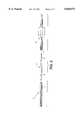
- FIG. 3is a schematic of a typical guidewire with a hypotube connector in position to receive the backloading wire and the distal end of a catheter.
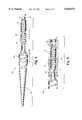
- FIG. 4is a fragmented diagram of an embodiment of the backloading wire having a helical coil at its distal end and a tapered proximal end.
- FIG. 5is an illustration of the distal end of the backloading wire having a helical coil engaged in the hypotube connector of a guidewire.
- the first embodiment of the backloading wire 3, shown in FIG. 1,measures approximately 5-14 centimeters in length.
- the center portion of the wire 9has a uniform diameter of approximately 0.014" and may be 1-10 centimeters in length.
- the tapered segments 8 at each endhave a diameter decreasing from approximately 0.014" to 0.007" over about a two centimeter length.
- the backloading wiremay be made from material commonly used for medical guidewires such as stainless steel.
- the taper at the endsmay be created by grinding.
- the wiremay be coated to increase the diameter of the free end of the wire and uncoated at the opposite end to allow for its insertion into the hypotube. The slightly increased diameter of the coated end helps provide a smooth transition to the increased diameter of the hypotube connector for the advancing catheter.
- a second embodiment of the backloading wireis shown at 12 in FIG. 2.
- the wiremay be made from a resilient material such as superelastic nitinol wire approximately 0.008" in diameter.
- the overall length of the wireis approximately 5 centimeters.
- the distal end of the wire 14is distorted into a wave shape to frictionally engage the inside of a hypotube connector and the proximal end of the wire 16 is straight.
- the straight proximal end 16may have a slightly rounded tip 18, to smoothly accept the guidewire lumen of a catheter.
- the wave shape distortionencompasses about half the length (approximately 2.5 cm) of the total length of the wire.
- the waveformmay be a two dimensional, zig-zag shape or may be a three dimensional, spiral shape created by wrapping the wire around a mandrel so that it becomes plastically deformed.
- the overall effective diameter of the distorted portion(measured from peak 20 to trough 21 of the waveform) may measure approximately 0.015" and should provide an interference fit with the inside diameter of a hypotube connector.
- the wave shapewill elastically deform slightly as surfaces engage.
- the wave shapeprovides secure frictional engagement with the hypotube, yet avoids a leak tight fit with the hypotube, thereby allowing the sterilization process to reach the inside of the hypotube if packaged in assembled form with the guidewire.
- the interference fit between the wave shape tip and hypotube connectorshould be tight enough to prevent inadvertent dislodging, yet loose enough to allow disengagement with gloved hands.
- a pulling force of 0.04-0.2 lbs. to remove the backloading wirehas been shown to provide adequate engagement.
- the surface of the wiremay be oxidized to darken the color so as to make it visually distinguishable from the guidewire.
- the wave shaped distal end 14(second embodiment) is engaged within a hypotube connector 1 at the proximal end of a guidewire 2.
- the free end of the backloading wirereceives the distal end of a catheter 4 to be backloaded onto the guidewire.
- the free end of the backloading wirepresents a reduced profile, compared to that of an open hypotube connector, facilitating alignment with and entry into the small guidewire lumen 5 of a catheter 4.
- the backloading wiremay be left in place throughout the procedure or removed from the hypotube connector to allow for connection of a full length extension wire.
- FIG. 4is a fragmented illustration of the third embodiment of the backloading wire shown generally at 25.
- a description of the wire connection system employed at the distal end of this backloading wire embodimentmay be found in U.S. Pat. 5,133,364 (Palermo et al.), the disclosure of which is hereby incorporated by reference herein, in its entirety.
- the overall length of the backloading wiremay be of the order of 12 centimeters.
- the wiremay be fabricated from material commonly used for guidewires such as stainless steel.
- the backloading wirehas a distal segment 27 of reduced diameter that holds a helical coil 29 that will engage the hypotube connector of the guidewire.
- the diameter of the wireincreases stepwise to a maximum diameter of approximately 0.014" at a central portion 31 of the wire.
- the central portionremains outside the hypotube connector during engagement and should have a comparable diameter to that of the guidewire shaft to provide a smooth transition between the wires.
- the proximal segment of the backloading wire 33tapers down from the maximum diameter of the central portion to a reduced diameter for easy insertion into the distal end of the catheter.
- the tapered proximal segmentmay measure approximately 2 centimeters in length, tapering from a diameter of approximately 0.014" near the central portion 31 to a diameter of approximately 0.007".
- the central portion 31(identified as segment A in FIG. 4) may span a length of approximately one centimeter.
- the tapered segment Bmay be about 0.5 centimeters long and may taper down to about 0.0055" diameter.
- the tapered segment Bmerges distally into constant diameter segment C which is approximately 0.0055" in diameter and about 1.5 centimeters in length.
- helical coil 29Mounted on the distal segment 27 (segment C) is helical coil 29 having a relaxed inner diameter slightly greater (about 0.001" to 0.002") than the diameter of the distal segment.
- the coilhas a relaxed outer diameter that is equal to or just slightly greater than the inner diameter of the hypotube connector to provide a light interference fit.
- the coil 29may be approximately 0.7 centimeter long and may have an outer diameter of 0.009" and an inner diameter of 0.007".
- the coilpreferably is wound from wire that is of generally flat rectangular cross-sectional configuration, preferably of the order of 0.001" by 0.005".
- the coilis of somewhat tapering diameter with a slightly larger diameter provided at several of the turns of the proximal end of the coil to assure a slight interference fit (of the order of 0.001" to 0.002" in diameter) between the coil and the inner surface of the hypotube.
- two or three turns at the proximal end of the coil 37may be of a slightly enlarged outer diameter, of the order of 0.010"-0.011".
- the coil 29is attached at its distal end to the distal segment of the backloading wire by brazing 35.
- the proximal end of the coil 37is free to permit the coil to stretch as well as constrict about the distal segment 27.
- the coil 29is of a length and is positioned so that the free proximal end 37 of the coil is not substantially more than 1.0 centimeter away from the distal tip 40 of the backloading wire.
- the backloading wire 25is joined to a guidewire 2 by inserting the distal end of the backloading wire 27 into the hypotube connector 1 at the proximal end of the guidewire 2.
- the turns of the coil 29engage, in light interference, the interior surface of the hypotube 1 to cause the coil to stretch longitudinally.
- the stretching of the coil 29causes its diameter to constrict, thereby enabling the coil to be inserted into the hypotube 1.
- the coil 29remains biased toward its expanded configuration causing the coil to bear against the interior surface of the hypotube 1.
- the rectangular cross-section of the wire from which the coil 29 is formeddefines relatively sharp, distinct edges 39 which may engage with the interior surface of the hypotube 1 to provide a relatively firm connection that is resistant to axial separation.
- the arrangementis self-latching and requires no other manipulation to make the connection.
- the backloading wire 25 and guidewire 1may be detached by applying an axial separation force while simultaneously twisting the backloading wire in a direction that will tend to constrict the coil 29 about the distal segment 27 of the backloading wire.
- the backloading wire 25would be twisted clockwise, as seen from the left in FIG. 5, while withdrawing it axially from the hypotube 1.
- the backloading wiremay be reconnected and disconnected from the hypotube as many times as needed.
- the helical coil 29can be made a sufficient length so as to protrude beyond the end of the hypotube 1 while the distal segment 27 of the backloading wire is fully engaged.
- the userwould simply grip the exposed proximal segment of the coil and pull it in a proximal direction to stretch the spring, reducing its diameter, and allow removal of the backloading wire from the hypotube 1.
Landscapes
- Health & Medical Sciences (AREA)
- Life Sciences & Earth Sciences (AREA)
- Biophysics (AREA)
- Pulmonology (AREA)
- Engineering & Computer Science (AREA)
- Anesthesiology (AREA)
- Biomedical Technology (AREA)
- Heart & Thoracic Surgery (AREA)
- Hematology (AREA)
- Animal Behavior & Ethology (AREA)
- General Health & Medical Sciences (AREA)
- Public Health (AREA)
- Veterinary Medicine (AREA)
- Media Introduction/Drainage Providing Device (AREA)
Abstract
Description
Claims (32)
Priority Applications (4)
| Application Number | Priority Date | Filing Date | Title |
|---|---|---|---|
| US08/667,943US5820571A (en) | 1996-06-24 | 1996-06-24 | Medical backloading wire |
| EP97931349AEP0921833A1 (en) | 1996-06-24 | 1997-06-24 | Medical backloading wire |
| PCT/US1997/010913WO1997049448A1 (en) | 1996-06-24 | 1997-06-24 | Medical backloading wire |
| JP50345698AJP2002501395A (en) | 1996-06-24 | 1997-06-24 | Medical back loading wire |
Applications Claiming Priority (1)
| Application Number | Priority Date | Filing Date | Title |
|---|---|---|---|
| US08/667,943US5820571A (en) | 1996-06-24 | 1996-06-24 | Medical backloading wire |
Publications (1)
| Publication Number | Publication Date |
|---|---|
| US5820571Atrue US5820571A (en) | 1998-10-13 |
Family
ID=24680311
Family Applications (1)
| Application Number | Title | Priority Date | Filing Date |
|---|---|---|---|
| US08/667,943Expired - Fee RelatedUS5820571A (en) | 1996-06-24 | 1996-06-24 | Medical backloading wire |
Country Status (4)
| Country | Link |
|---|---|
| US (1) | US5820571A (en) |
| EP (1) | EP0921833A1 (en) |
| JP (1) | JP2002501395A (en) |
| WO (1) | WO1997049448A1 (en) |
Cited By (38)
| Publication number | Priority date | Publication date | Assignee | Title |
|---|---|---|---|---|
| US6544231B1 (en)* | 2000-05-22 | 2003-04-08 | Medcanica, Inc. | Catch, stop and marker assembly for a medical instrument and medical instrument incorporating the same |
| US20030069520A1 (en)* | 2001-10-05 | 2003-04-10 | Scimed Life Systems, Inc. | Guidewire with stiffness blending connection |
| US6638267B1 (en) | 2000-12-01 | 2003-10-28 | Advanced Cardiovascular Systems, Inc. | Guidewire with hypotube and internal insert |
| US20040106878A1 (en)* | 2002-12-03 | 2004-06-03 | Scimed Life Systems, Inc. | Composite medical device with markers |
| US20040167441A1 (en)* | 2003-02-26 | 2004-08-26 | Reynolds Brian R. | Composite medical device |
| US20050065456A1 (en)* | 2003-09-22 | 2005-03-24 | Scimed Life Systems, Inc. | Guidewire with reinforcing member |
| US20060122537A1 (en)* | 2001-10-05 | 2006-06-08 | Brian Reynolds | Composite guidewire |
| US20060253049A1 (en)* | 2003-01-14 | 2006-11-09 | Radi Medical Systems Ab | Method for introducer replacement |
| US8172857B2 (en) | 2004-08-27 | 2012-05-08 | Davol, Inc. | Endoscopic tissue apposition device and method of use |
| US8337519B2 (en) | 2003-07-10 | 2012-12-25 | Boston Scientific Scimed, Inc. | Embolic protection filtering device |
| US8900060B2 (en) | 2009-04-29 | 2014-12-02 | Ecp Entwicklungsgesellschaft Mbh | Shaft arrangement having a shaft which extends within a fluid-filled casing |
| US8926492B2 (en) | 2011-10-11 | 2015-01-06 | Ecp Entwicklungsgesellschaft Mbh | Housing for a functional element |
| US8932141B2 (en) | 2009-10-23 | 2015-01-13 | Ecp Entwicklungsgesellschaft Mbh | Flexible shaft arrangement |
| US8944748B2 (en) | 2009-05-05 | 2015-02-03 | Ecp Entwicklungsgesellschaft Mbh | Fluid pump changeable in diameter, in particular for medical application |
| US8979493B2 (en) | 2009-03-18 | 2015-03-17 | ECP Entwicklungsgesellscaft mbH | Fluid pump |
| US8998792B2 (en) | 2008-12-05 | 2015-04-07 | Ecp Entwicklungsgesellschaft Mbh | Fluid pump with a rotor |
| US9028216B2 (en) | 2009-09-22 | 2015-05-12 | Ecp Entwicklungsgesellschaft Mbh | Rotor for an axial flow pump for conveying a fluid |
| US9067006B2 (en) | 2009-06-25 | 2015-06-30 | Ecp Entwicklungsgesellschaft Mbh | Compressible and expandable blade for a fluid pump |
| US9089634B2 (en) | 2009-09-22 | 2015-07-28 | Ecp Entwicklungsgesellschaft Mbh | Fluid pump having at least one impeller blade and a support device |
| US9089670B2 (en) | 2009-02-04 | 2015-07-28 | Ecp Entwicklungsgesellschaft Mbh | Catheter device having a catheter and an actuation device |
| US9217442B2 (en) | 2010-03-05 | 2015-12-22 | Ecp Entwicklungsgesellschaft Mbh | Pump or rotary cutter for operation in a fluid |
| US9314558B2 (en) | 2009-12-23 | 2016-04-19 | Ecp Entwicklungsgesellschaft Mbh | Conveying blades for a compressible rotor |
| US9328741B2 (en) | 2010-05-17 | 2016-05-03 | Ecp Entwicklungsgesellschaft Mbh | Pump arrangement |
| US9339596B2 (en) | 2009-12-23 | 2016-05-17 | Ecp Entwicklungsgesellschaft Mbh | Radially compressible and expandable rotor for a fluid pump |
| US9358330B2 (en) | 2009-12-23 | 2016-06-07 | Ecp Entwicklungsgesellschaft Mbh | Pump device having a detection device |
| US9416791B2 (en) | 2010-01-25 | 2016-08-16 | Ecp Entwicklungsgesellschaft Mbh | Fluid pump having a radially compressible rotor |
| US9416783B2 (en) | 2009-09-22 | 2016-08-16 | Ecp Entwicklungsgellschaft Mbh | Compressible rotor for a fluid pump |
| US9603983B2 (en) | 2009-10-23 | 2017-03-28 | Ecp Entwicklungsgesellschaft Mbh | Catheter pump arrangement and flexible shaft arrangement having a core |
| WO2017053361A1 (en)* | 2015-09-22 | 2017-03-30 | Abiomed, Inc. | Guidewire for cannula placement |
| US9611743B2 (en) | 2010-07-15 | 2017-04-04 | Ecp Entwicklungsgesellschaft Mbh | Radially compressible and expandable rotor for a pump having an impeller blade |
| US9771801B2 (en) | 2010-07-15 | 2017-09-26 | Ecp Entwicklungsgesellschaft Mbh | Rotor for a pump, produced with a first elastic material |
| US9867916B2 (en) | 2010-08-27 | 2018-01-16 | Berlin Heart Gmbh | Implantable blood conveying device, manipulating device and coupling device |
| US9895475B2 (en) | 2010-07-15 | 2018-02-20 | Ecp Entwicklungsgesellschaft Mbh | Blood pump for the invasive application within a body of a patient |
| US9974893B2 (en) | 2010-06-25 | 2018-05-22 | Ecp Entwicklungsgesellschaft Mbh | System for introducing a pump |
| US10107299B2 (en) | 2009-09-22 | 2018-10-23 | Ecp Entwicklungsgesellschaft Mbh | Functional element, in particular fluid pump, having a housing and a conveying element |
| US10172985B2 (en) | 2009-08-06 | 2019-01-08 | Ecp Entwicklungsgesellschaft Mbh | Catheter device having a coupling device for a drive device |
| US10391278B2 (en) | 2011-03-10 | 2019-08-27 | Ecp Entwicklungsgesellschaft Mbh | Push device for the axial insertion of an elongate, flexible body |
| US10561773B2 (en) | 2011-09-05 | 2020-02-18 | Ecp Entwicklungsgesellschaft Mbh | Medical product comprising a functional element for the invasive use in a patient's body |
Families Citing this family (1)
| Publication number | Priority date | Publication date | Assignee | Title |
|---|---|---|---|---|
| JP2011147580A (en)* | 2010-01-21 | 2011-08-04 | Munetaka Kumate | Guide wire |
Citations (21)
| Publication number | Priority date | Publication date | Assignee | Title |
|---|---|---|---|---|
| US4659328A (en)* | 1984-03-12 | 1987-04-21 | Biosearch Medical Products, Inc. | Stylet |
| US4827941A (en)* | 1987-12-23 | 1989-05-09 | Advanced Cardiovascular Systems, Inc. | Extendable guidewire for cardiovascular procedures |
| US4958642A (en)* | 1988-11-02 | 1990-09-25 | Cardiometrics, Inc. | Guide wire assembly with electrical functions and male and female connectors for use therewith |
| US4961433A (en)* | 1988-11-02 | 1990-10-09 | Cardiometrics, Inc. | Guide wire assembly with electrical functions and male and female connectors for use therewith |
| US4991602A (en)* | 1989-06-27 | 1991-02-12 | Flexmedics Corporation | Flexible guide wire with safety tip |
| US5109867A (en)* | 1991-04-19 | 1992-05-05 | Target Therapeutics | Extendable guidewire assembly |
| US5113872A (en)* | 1990-04-18 | 1992-05-19 | Cordis Corporation | Guidewire extension system with connectors |
| US5133364A (en)* | 1988-06-13 | 1992-07-28 | C. R. Bard, Inc. | Guidewire extension with self-latching detachable connector |
| US5188621A (en)* | 1991-08-26 | 1993-02-23 | Target Therapeutics Inc. | Extendable guidewire assembly |
| US5267573A (en)* | 1992-11-13 | 1993-12-07 | Oakley, Inc. | Guidewire extender |
| USRE34466E (en)* | 1987-12-23 | 1993-12-07 | Advanced Cardiovascular Systems, Inc. | Extendable guidewire for cardiovascular procedures |
| US5271415A (en)* | 1992-01-28 | 1993-12-21 | Baxter International Inc. | Guidewire extension system |
| EP0591945A1 (en)* | 1992-10-09 | 1994-04-13 | C.R. Bard, Inc. | Guidewire extension with selflatching detachable connector |
| US5327885A (en)* | 1991-10-08 | 1994-07-12 | Griffith James M | Combination catheter for invasive probe delivery and balloon dilation |
| US5357978A (en)* | 1993-01-12 | 1994-10-25 | Medtronic, Inc. | Rapid exchange guidewire loading attachment |
| US5363847A (en)* | 1993-10-27 | 1994-11-15 | Cordis Corporation | Guidewire having double distal portions |
| US5365943A (en)* | 1993-03-12 | 1994-11-22 | C. R. Bard, Inc. | Anatomically matched steerable PTCA guidewire |
| US5404888A (en)* | 1992-02-10 | 1995-04-11 | Datascope Investment Corp. | Guide wire extension |
| US5415178A (en)* | 1991-08-26 | 1995-05-16 | Target Therapeutics | Extendable guidewire assembly |
| US5497782A (en)* | 1994-04-28 | 1996-03-12 | Medtronic, Inc. | Lockable guidewire |
| US5507729A (en)* | 1993-01-28 | 1996-04-16 | Angiomed Ag | One-piece guide part and process for the production thereof |
- 1996
- 1996-06-24USUS08/667,943patent/US5820571A/ennot_activeExpired - Fee Related
- 1997
- 1997-06-24EPEP97931349Apatent/EP0921833A1/ennot_activeWithdrawn
- 1997-06-24JPJP50345698Apatent/JP2002501395A/enactivePending
- 1997-06-24WOPCT/US1997/010913patent/WO1997049448A1/ennot_activeApplication Discontinuation
Patent Citations (22)
| Publication number | Priority date | Publication date | Assignee | Title |
|---|---|---|---|---|
| US4659328A (en)* | 1984-03-12 | 1987-04-21 | Biosearch Medical Products, Inc. | Stylet |
| USRE34466E (en)* | 1987-12-23 | 1993-12-07 | Advanced Cardiovascular Systems, Inc. | Extendable guidewire for cardiovascular procedures |
| US4827941A (en)* | 1987-12-23 | 1989-05-09 | Advanced Cardiovascular Systems, Inc. | Extendable guidewire for cardiovascular procedures |
| US5133364A (en)* | 1988-06-13 | 1992-07-28 | C. R. Bard, Inc. | Guidewire extension with self-latching detachable connector |
| US4958642A (en)* | 1988-11-02 | 1990-09-25 | Cardiometrics, Inc. | Guide wire assembly with electrical functions and male and female connectors for use therewith |
| US4961433A (en)* | 1988-11-02 | 1990-10-09 | Cardiometrics, Inc. | Guide wire assembly with electrical functions and male and female connectors for use therewith |
| US4991602A (en)* | 1989-06-27 | 1991-02-12 | Flexmedics Corporation | Flexible guide wire with safety tip |
| US5113872A (en)* | 1990-04-18 | 1992-05-19 | Cordis Corporation | Guidewire extension system with connectors |
| US5109867A (en)* | 1991-04-19 | 1992-05-05 | Target Therapeutics | Extendable guidewire assembly |
| US5188621A (en)* | 1991-08-26 | 1993-02-23 | Target Therapeutics Inc. | Extendable guidewire assembly |
| US5275173A (en)* | 1991-08-26 | 1994-01-04 | Target Therapeutics, Inc. | Extendable guidewire assembly |
| US5415178A (en)* | 1991-08-26 | 1995-05-16 | Target Therapeutics | Extendable guidewire assembly |
| US5327885A (en)* | 1991-10-08 | 1994-07-12 | Griffith James M | Combination catheter for invasive probe delivery and balloon dilation |
| US5271415A (en)* | 1992-01-28 | 1993-12-21 | Baxter International Inc. | Guidewire extension system |
| US5404888A (en)* | 1992-02-10 | 1995-04-11 | Datascope Investment Corp. | Guide wire extension |
| EP0591945A1 (en)* | 1992-10-09 | 1994-04-13 | C.R. Bard, Inc. | Guidewire extension with selflatching detachable connector |
| US5267573A (en)* | 1992-11-13 | 1993-12-07 | Oakley, Inc. | Guidewire extender |
| US5357978A (en)* | 1993-01-12 | 1994-10-25 | Medtronic, Inc. | Rapid exchange guidewire loading attachment |
| US5507729A (en)* | 1993-01-28 | 1996-04-16 | Angiomed Ag | One-piece guide part and process for the production thereof |
| US5365943A (en)* | 1993-03-12 | 1994-11-22 | C. R. Bard, Inc. | Anatomically matched steerable PTCA guidewire |
| US5363847A (en)* | 1993-10-27 | 1994-11-15 | Cordis Corporation | Guidewire having double distal portions |
| US5497782A (en)* | 1994-04-28 | 1996-03-12 | Medtronic, Inc. | Lockable guidewire |
Cited By (127)
| Publication number | Priority date | Publication date | Assignee | Title |
|---|---|---|---|---|
| US6544231B1 (en)* | 2000-05-22 | 2003-04-08 | Medcanica, Inc. | Catch, stop and marker assembly for a medical instrument and medical instrument incorporating the same |
| US6638267B1 (en) | 2000-12-01 | 2003-10-28 | Advanced Cardiovascular Systems, Inc. | Guidewire with hypotube and internal insert |
| US7618379B2 (en) | 2001-10-05 | 2009-11-17 | Boston Scientific Scimed, Inc. | Composite guidewire |
| US20030069520A1 (en)* | 2001-10-05 | 2003-04-10 | Scimed Life Systems, Inc. | Guidewire with stiffness blending connection |
| US8414506B2 (en) | 2001-10-05 | 2013-04-09 | Boston Scientific Scimed, Inc. | Composite guidewire |
| US7993286B2 (en) | 2001-10-05 | 2011-08-09 | Boston Scientific Scimed, Inc. | Composite guidewire |
| US20060122537A1 (en)* | 2001-10-05 | 2006-06-08 | Brian Reynolds | Composite guidewire |
| US7074197B2 (en) | 2001-10-05 | 2006-07-11 | Scimed Life Systems, Inc. | Composite guidewire |
| US6918882B2 (en) | 2001-10-05 | 2005-07-19 | Scimed Life Systems, Inc. | Guidewire with stiffness blending connection |
| US20070135734A1 (en)* | 2001-10-05 | 2007-06-14 | Boston Scientific Scimed, Inc. | Composite guidewire |
| US20070244414A1 (en)* | 2001-10-05 | 2007-10-18 | Boston Scientific Scimed, Inc. | Composite guidewire |
| US7951093B2 (en) | 2002-12-03 | 2011-05-31 | Boston Scientific Scimed, Inc. | Composite medical device with markers |
| US7153277B2 (en) | 2002-12-03 | 2006-12-26 | Scimed Life Systems, Inc. | Composite medical device with markers |
| US20070112282A1 (en)* | 2002-12-03 | 2007-05-17 | Boston Scientific Scimed, Inc. | Composite medical device with markers |
| US20040106878A1 (en)* | 2002-12-03 | 2004-06-03 | Scimed Life Systems, Inc. | Composite medical device with markers |
| US20060253049A1 (en)* | 2003-01-14 | 2006-11-09 | Radi Medical Systems Ab | Method for introducer replacement |
| US8734366B2 (en)* | 2003-01-14 | 2014-05-27 | Radi Medical Systems Ab | Guide rod for introducer replacement |
| US20040167441A1 (en)* | 2003-02-26 | 2004-08-26 | Reynolds Brian R. | Composite medical device |
| US8337519B2 (en) | 2003-07-10 | 2012-12-25 | Boston Scientific Scimed, Inc. | Embolic protection filtering device |
| US7785273B2 (en) | 2003-09-22 | 2010-08-31 | Boston Scientific Scimed, Inc. | Guidewire with reinforcing member |
| US20050065456A1 (en)* | 2003-09-22 | 2005-03-24 | Scimed Life Systems, Inc. | Guidewire with reinforcing member |
| US8172857B2 (en) | 2004-08-27 | 2012-05-08 | Davol, Inc. | Endoscopic tissue apposition device and method of use |
| US9149270B2 (en) | 2004-08-27 | 2015-10-06 | Davol, Inc. (a C.R. Bard Company) | Endoscopic tissue apposition device and method of use |
| US10495101B2 (en) | 2008-12-05 | 2019-12-03 | Ecp Entwicklungsgesellschaft Mbh | Fluid pump with a rotor |
| US10662967B2 (en) | 2008-12-05 | 2020-05-26 | Ecp Entwicklungsgesellschaft Mbh | Fluid pump with a rotor |
| US9964115B2 (en) | 2008-12-05 | 2018-05-08 | Ecp Entwicklungsgesellschaft Mbh | Fluid pump with a rotor |
| US11852155B2 (en) | 2008-12-05 | 2023-12-26 | Ecp Entwicklungsgesellschaft Mbh | Fluid pump with a rotor |
| US8998792B2 (en) | 2008-12-05 | 2015-04-07 | Ecp Entwicklungsgesellschaft Mbh | Fluid pump with a rotor |
| US9404505B2 (en) | 2008-12-05 | 2016-08-02 | Ecp Entwicklungsgesellschaft Mbh | Fluid pump with a rotor |
| US12209593B2 (en) | 2008-12-05 | 2025-01-28 | Ecp Entwicklungsgesellschaft Mbh | Fluid pump with a rotor |
| US9089670B2 (en) | 2009-02-04 | 2015-07-28 | Ecp Entwicklungsgesellschaft Mbh | Catheter device having a catheter and an actuation device |
| US9981110B2 (en) | 2009-02-04 | 2018-05-29 | Ecp Entwicklungsgesellschaft Mbh | Catheter device having a catheter and an actuation device |
| US10406323B2 (en) | 2009-02-04 | 2019-09-10 | Ecp Entwicklungsgesellschaft Mbh | Catheter device having a catheter and an actuation device |
| US11229774B2 (en) | 2009-02-04 | 2022-01-25 | Ecp Entwicklungsgesellschaft Mbh | Catheter device having a catheter and an actuation device |
| US12377246B2 (en) | 2009-02-04 | 2025-08-05 | Ecp Entwicklungsgesellschaft Mbh | Catheter device having a catheter and an actuation device |
| US9649475B2 (en) | 2009-02-04 | 2017-05-16 | Ecp Entwicklungsgesellschaft Mbh | Catheter device having a catheter and an actuation device |
| US11969560B2 (en) | 2009-02-04 | 2024-04-30 | Ecp Entwicklungsgesellschaft Mbh | Catheter device having a catheter and an actuation device |
| US8979493B2 (en) | 2009-03-18 | 2015-03-17 | ECP Entwicklungsgesellscaft mbH | Fluid pump |
| US8900060B2 (en) | 2009-04-29 | 2014-12-02 | Ecp Entwicklungsgesellschaft Mbh | Shaft arrangement having a shaft which extends within a fluid-filled casing |
| US9512839B2 (en) | 2009-05-05 | 2016-12-06 | Ecp Entwicklungsgesellschaft Mbh | Fluid pump changeable in diameter, in particular for medical application |
| US10265448B2 (en) | 2009-05-05 | 2019-04-23 | Ecp Entwicklungsgesellschaft Mbh | Fluid pump changeable in diameter, in particular for medical application |
| US11278711B2 (en) | 2009-05-05 | 2022-03-22 | Ecp Entwicklungsgesellschaft Mbh | Fluid pump changeable in diameter, in particular for medical application |
| US8944748B2 (en) | 2009-05-05 | 2015-02-03 | Ecp Entwicklungsgesellschaft Mbh | Fluid pump changeable in diameter, in particular for medical application |
| US11577066B2 (en) | 2009-05-05 | 2023-02-14 | Ecp Entwicklundgesellschaft Mbh | Fluid pump changeable in diameter, in particular for medical application |
| US11786718B2 (en) | 2009-05-05 | 2023-10-17 | Ecp Entwicklungsgesellschaft Mbh | Fluid pump changeable in diameter, in particular for medical application |
| US9067006B2 (en) | 2009-06-25 | 2015-06-30 | Ecp Entwicklungsgesellschaft Mbh | Compressible and expandable blade for a fluid pump |
| US10330101B2 (en) | 2009-06-25 | 2019-06-25 | Ecp Entwicklungsgesellschaft Mbh | Compressible and expandable blade for a fluid pump |
| US12372092B2 (en) | 2009-06-25 | 2025-07-29 | Ecp Entwicklungsgesellschaft Mbh | Compressible and expandable blade for a fluid pump |
| US11994133B2 (en) | 2009-06-25 | 2024-05-28 | Ecp Entwicklungsgesellschaft Mbh | Compressible and expandable blade for a fluid pump |
| US11268521B2 (en) | 2009-06-25 | 2022-03-08 | Ecp Entwicklungsgesellschaft Mbh | Compressible and expandable blade for a fluid pump |
| US10172985B2 (en) | 2009-08-06 | 2019-01-08 | Ecp Entwicklungsgesellschaft Mbh | Catheter device having a coupling device for a drive device |
| US11116960B2 (en) | 2009-08-06 | 2021-09-14 | Ecp Entwicklungsgesellschaft Mbh | Catheter device having a coupling device for a drive device |
| US12042647B2 (en) | 2009-08-06 | 2024-07-23 | Ecp Entwicklungsgesellschaft Mbh | Catheter device having a coupling device for a drive device |
| US11592028B2 (en) | 2009-09-22 | 2023-02-28 | Ecp Entwicklungsgesellschaft Mbh | Fluid pump having at least one impeller blade and a support device |
| US12276285B2 (en) | 2009-09-22 | 2025-04-15 | Ecp Entwicklungsgesellschaft Mbh | Compressible rotor for a fluid pump |
| US9089634B2 (en) | 2009-09-22 | 2015-07-28 | Ecp Entwicklungsgesellschaft Mbh | Fluid pump having at least one impeller blade and a support device |
| US11773861B2 (en) | 2009-09-22 | 2023-10-03 | Ecp Entwicklungsgesellschaft Mbh | Compressible rotor for a fluid pump |
| US11421701B2 (en) | 2009-09-22 | 2022-08-23 | Ecp Entwicklungsgesellschaft Mbh | Compressible rotor for a fluid pump |
| US10107299B2 (en) | 2009-09-22 | 2018-10-23 | Ecp Entwicklungsgesellschaft Mbh | Functional element, in particular fluid pump, having a housing and a conveying element |
| US9416783B2 (en) | 2009-09-22 | 2016-08-16 | Ecp Entwicklungsgellschaft Mbh | Compressible rotor for a fluid pump |
| US10208763B2 (en) | 2009-09-22 | 2019-02-19 | Ecp Entwicklungsgesellschaft Mbh | Fluid pump having at least one impeller blade and a support device |
| US9028216B2 (en) | 2009-09-22 | 2015-05-12 | Ecp Entwicklungsgesellschaft Mbh | Rotor for an axial flow pump for conveying a fluid |
| US12066030B2 (en) | 2009-09-22 | 2024-08-20 | Ecp Entwicklungsgesellschaft Mbh | Fluid pump having at least one impeller blade and a support device |
| US9603983B2 (en) | 2009-10-23 | 2017-03-28 | Ecp Entwicklungsgesellschaft Mbh | Catheter pump arrangement and flexible shaft arrangement having a core |
| US10792406B2 (en) | 2009-10-23 | 2020-10-06 | Ecp Entwicklungsgesellschaft Mbh | Catheter pump arrangement and flexible shaft arrangement having a core |
| US12313113B2 (en) | 2009-10-23 | 2025-05-27 | Ecp Entwicklungsgesellschaft Mbh | Catheter pump arrangement and flexible shaft arrangement having a core |
| US8932141B2 (en) | 2009-10-23 | 2015-01-13 | Ecp Entwicklungsgesellschaft Mbh | Flexible shaft arrangement |
| US11549517B2 (en) | 2009-12-23 | 2023-01-10 | Ecp Entwicklungsgesellschaft Mbh | Conveying blades for a compressible rotor |
| US9795727B2 (en) | 2009-12-23 | 2017-10-24 | Ecp Entwicklungsgesellschaft Mbh | Pump device having a detection device |
| US11815097B2 (en) | 2009-12-23 | 2023-11-14 | Ecp Entwicklungsgesellschaft Mbh | Pump device having a detection device |
| US10557475B2 (en) | 2009-12-23 | 2020-02-11 | Ecp Entwicklungsgesellschaft Mbh | Radially compressible and expandable rotor for a fluid pump |
| US9314558B2 (en) | 2009-12-23 | 2016-04-19 | Ecp Entwicklungsgesellschaft Mbh | Conveying blades for a compressible rotor |
| US10561772B2 (en) | 2009-12-23 | 2020-02-18 | Ecp Entwicklungsgesellschaft Mbh | Pump device having a detection device |
| US11781557B2 (en) | 2009-12-23 | 2023-10-10 | Ecp Entwicklungsgesellschaft Mbh | Radially compressible and expandable rotor for a fluid pump |
| US11773863B2 (en) | 2009-12-23 | 2023-10-03 | Ecp Entwicklungsgesellschaft Mbh | Conveying blades for a compressible rotor |
| US9358330B2 (en) | 2009-12-23 | 2016-06-07 | Ecp Entwicklungsgesellschaft Mbh | Pump device having a detection device |
| US12305662B2 (en) | 2009-12-23 | 2025-05-20 | Ecp Entwicklungsgesellschaft Mbh | Conveying blades for a compressible rotor |
| US10806838B2 (en) | 2009-12-23 | 2020-10-20 | Ecp Entwicklungsgesellschaft Mbh | Conveying blades for a compressible rotor |
| US12085088B2 (en) | 2009-12-23 | 2024-09-10 | Ecp Entwicklungsgesellschaft Mbh | Radially compressible and expandable rotor for a fluid pump |
| US12117014B2 (en) | 2009-12-23 | 2024-10-15 | Ecp Entwicklungsgesellschaft Mbh | Conveying blades for a compressible rotor |
| US11486400B2 (en) | 2009-12-23 | 2022-11-01 | Ecp Entwicklungsgesellschaft Mbh | Pump device having a detection device |
| US11434922B2 (en) | 2009-12-23 | 2022-09-06 | Ecp Entwicklungsgesellschaft Mbh | Radially compressible and expandable rotor for a fluid pump |
| US9903384B2 (en) | 2009-12-23 | 2018-02-27 | Ecp Entwicklungsgesellschaft Mbh | Radially compressible and expandable rotor for a fluid pump |
| US12158151B2 (en) | 2009-12-23 | 2024-12-03 | Ecp Entwicklungsgesellschaft Mbh | Pump device having a detection device |
| US11266824B2 (en) | 2009-12-23 | 2022-03-08 | Ecp Entwicklungsgesellschaft Mbh | Conveying blades for a compressible rotor |
| US9339596B2 (en) | 2009-12-23 | 2016-05-17 | Ecp Entwicklungsgesellschaft Mbh | Radially compressible and expandable rotor for a fluid pump |
| US11517739B2 (en) | 2010-01-25 | 2022-12-06 | Ecp Entwicklungsgesellschaft Mbh | Fluid pump having a radially compressible rotor |
| US12018698B2 (en) | 2010-01-25 | 2024-06-25 | Ecp Entwicklungsgesellschaft Mbh | Fluid pump having a radially compressible rotor |
| US10316853B2 (en) | 2010-01-25 | 2019-06-11 | Ecp Entwicklungsgesellschaft Mbh | Fluid pump having a radially compressible rotor |
| US9416791B2 (en) | 2010-01-25 | 2016-08-16 | Ecp Entwicklungsgesellschaft Mbh | Fluid pump having a radially compressible rotor |
| US10413646B2 (en) | 2010-03-05 | 2019-09-17 | Ecp Entwicklungsgesellschaft Mbh | Pump or rotary cutter for operation in a fluid |
| US9217442B2 (en) | 2010-03-05 | 2015-12-22 | Ecp Entwicklungsgesellschaft Mbh | Pump or rotary cutter for operation in a fluid |
| US9907891B2 (en) | 2010-03-05 | 2018-03-06 | Ecp Entwicklungsgesellschaft Mbh | Pump or rotary cutter for operation in a fluid |
| US11986205B2 (en) | 2010-03-05 | 2024-05-21 | Ecp Entwicklungsgesellschaft Mbh | Pump or rotary cutter for operation in a fluid |
| US9328741B2 (en) | 2010-05-17 | 2016-05-03 | Ecp Entwicklungsgesellschaft Mbh | Pump arrangement |
| US11976674B2 (en) | 2010-05-17 | 2024-05-07 | Ecp Entwicklungsgesellschaft Mbh | Pump arrangement |
| US10221866B2 (en) | 2010-05-17 | 2019-03-05 | Ecp Entwicklungsgesellschaft Mbh | Pump arrangement |
| US11168705B2 (en) | 2010-05-17 | 2021-11-09 | Ecp Entwicklungsgesellschaft Mbh | Pump arrangement |
| US9759237B2 (en) | 2010-05-17 | 2017-09-12 | Ecp Entwicklungsgesellschaft Mbh | Pump arrangement |
| US9974893B2 (en) | 2010-06-25 | 2018-05-22 | Ecp Entwicklungsgesellschaft Mbh | System for introducing a pump |
| US10898625B2 (en) | 2010-06-25 | 2021-01-26 | Ecp Entwicklungsgesellschaft Mbh | System for introducing a pump |
| US10874781B2 (en) | 2010-06-25 | 2020-12-29 | Ecp Entwicklungsgesellschaft Mbh | System for introducing a pump |
| US11957846B2 (en) | 2010-06-25 | 2024-04-16 | Ecp Entwicklungsgesellschaft Mbh | System for introducing a pump |
| US10920596B2 (en) | 2010-07-15 | 2021-02-16 | Ecp Entwicklungsgesellschaft Mbh | Radially compressible and expandable rotor for a pump having an impeller blade |
| US9771801B2 (en) | 2010-07-15 | 2017-09-26 | Ecp Entwicklungsgesellschaft Mbh | Rotor for a pump, produced with a first elastic material |
| US11844939B2 (en) | 2010-07-15 | 2023-12-19 | Ecp Entwicklungsgesellschaft Mbh | Blood pump for the invasive application within a body of a patient |
| US10584589B2 (en) | 2010-07-15 | 2020-03-10 | Ecp Entwicklungsgellschaft Mbh | Rotor for a pump having helical expandable blades |
| US11913467B2 (en) | 2010-07-15 | 2024-02-27 | Ecp Entwicklungsgesellschaft Mbh | Radially compressible and expandable rotor for a pump having an impeller blade |
| US10589012B2 (en) | 2010-07-15 | 2020-03-17 | Ecp Entwicklungsgesellschaft Mbh | Blood pump for the invasive application within a body of a patient |
| US9611743B2 (en) | 2010-07-15 | 2017-04-04 | Ecp Entwicklungsgesellschaft Mbh | Radially compressible and expandable rotor for a pump having an impeller blade |
| US11702938B2 (en) | 2010-07-15 | 2023-07-18 | Ecp Entwicklungsgesellschaft Mbh | Rotor for a pump, produced with a first elastic material |
| US12065941B2 (en) | 2010-07-15 | 2024-08-20 | Ecp Entwicklungsgesellschaft Mbh | Rotor for a pump, produced with a first elastic material |
| US9895475B2 (en) | 2010-07-15 | 2018-02-20 | Ecp Entwicklungsgesellschaft Mbh | Blood pump for the invasive application within a body of a patient |
| US11083885B2 (en) | 2010-08-27 | 2021-08-10 | Berlin Heart Gmbh | Implantable blood conveying device, manipulating device and coupling device |
| US9867916B2 (en) | 2010-08-27 | 2018-01-16 | Berlin Heart Gmbh | Implantable blood conveying device, manipulating device and coupling device |
| US10391278B2 (en) | 2011-03-10 | 2019-08-27 | Ecp Entwicklungsgesellschaft Mbh | Push device for the axial insertion of an elongate, flexible body |
| US11235125B2 (en) | 2011-03-10 | 2022-02-01 | Ecp Entwicklungsgesellschaft Mbh | Push device for the axial insertion of an elongate, flexible body |
| US10561773B2 (en) | 2011-09-05 | 2020-02-18 | Ecp Entwicklungsgesellschaft Mbh | Medical product comprising a functional element for the invasive use in a patient's body |
| US11666746B2 (en) | 2011-09-05 | 2023-06-06 | Ecp Entwicklungsgesellschaft Mbh | Medical product comprising a functional element for the invasive use in a patient's body |
| US8926492B2 (en) | 2011-10-11 | 2015-01-06 | Ecp Entwicklungsgesellschaft Mbh | Housing for a functional element |
| US9821146B2 (en) | 2015-09-22 | 2017-11-21 | Abiomed, Inc. | Guidewire for cannula placement |
| US20180104453A1 (en)* | 2015-09-22 | 2018-04-19 | Abiomed, Inc. | Guidewire for cannula placement |
| US11007350B2 (en) | 2015-09-22 | 2021-05-18 | Abiomed, Inc. | Guidewire for cannula placement |
| US10300249B2 (en)* | 2015-09-22 | 2019-05-28 | Abiomed, Inc. | Guidewire for cannula placement |
| WO2017053361A1 (en)* | 2015-09-22 | 2017-03-30 | Abiomed, Inc. | Guidewire for cannula placement |
| US11752308B2 (en) | 2015-09-22 | 2023-09-12 | Abiomed, Inc. | Guidewire for cannula placement |
| US12403287B2 (en) | 2015-09-22 | 2025-09-02 | Abiomed, Inc. | Guidewire for cannula placement |
Also Published As
| Publication number | Publication date |
|---|---|
| WO1997049448A1 (en) | 1997-12-31 |
| JP2002501395A (en) | 2002-01-15 |
| EP0921833A1 (en) | 1999-06-16 |
Similar Documents
| Publication | Publication Date | Title |
|---|---|---|
| US5820571A (en) | Medical backloading wire | |
| JP2571850B2 (en) | Self-latching connector | |
| US20190240462A1 (en) | Guidewire with adjustable stiffness | |
| EP0466412B1 (en) | Device for retrieving stents | |
| US8075608B2 (en) | Medical device delivery system | |
| US4699611A (en) | Biliary stent introducer | |
| US5776079A (en) | Retrograde-antegrade catheterization guide wire | |
| US20080281228A1 (en) | Guidewire with adjustable stiffness | |
| US5944701A (en) | Self coiling catheter | |
| EP2528517B1 (en) | Shapeable retrieval device | |
| US5830156A (en) | Slip resistant guidewire | |
| US5195535A (en) | Detachable guidewire extension | |
| EP0591945A1 (en) | Guidewire extension with selflatching detachable connector | |
| US20090062769A1 (en) | Rapid exchange catheter converter | |
| EP0747081A2 (en) | Rapid exchanger guidewire mechanism | |
| EP2745871B1 (en) | Guide wire | |
| EP0178094A1 (en) | Wire guided dilator device | |
| WO2010104558A2 (en) | Guidewire with adjustable stiffness |
Legal Events
| Date | Code | Title | Description |
|---|---|---|---|
| AS | Assignment | Owner name:C.R. BARD, INC., NEW JERSEY Free format text:ASSIGNMENT OF ASSIGNORS INTEREST;ASSIGNOR:ERADES, PIERRE;REEL/FRAME:008166/0191 Effective date:19960902 Owner name:C.R. BARD, INC., NEW JERSEY Free format text:ASSIGNMENT OF ASSIGNORS INTEREST;ASSIGNOR:ANTHONY, TOMAS RAYMOND;REEL/FRAME:008144/0874 Effective date:19960902 Owner name:C.R. BARD, INC., NEW JERSEY Free format text:ASSIGNMENT OF ASSIGNORS INTEREST;ASSIGNOR:GAMBALE, RICHARD A.;REEL/FRAME:008144/0868 Effective date:19960827 | |
| AS | Assignment | Owner name:ARTERIAL VASCULAR ENGINEERING, INC., CALIFORNIA Free format text:ASSIGNMENT OF ASSIGNORS INTEREST;ASSIGNOR:C.R. BARD, INC.;REEL/FRAME:009833/0062 Effective date:19981001 Owner name:MEDTRONIC AVE, INC., CALIFORNIA Free format text:MERGER;ASSIGNORS:MAV MERGER CORPORATION;ARTERIAL VASCULAR ENGINEERING, INC.;REEL/FRAME:009833/0068 Effective date:19990128 | |
| FPAY | Fee payment | Year of fee payment:4 | |
| REMI | Maintenance fee reminder mailed | ||
| LAPS | Lapse for failure to pay maintenance fees | ||
| STCH | Information on status: patent discontinuation | Free format text:PATENT EXPIRED DUE TO NONPAYMENT OF MAINTENANCE FEES UNDER 37 CFR 1.362 | |
| FP | Lapsed due to failure to pay maintenance fee | Effective date:20061013 |