US5820555A - Method for selectively creating and altering the shape of a body cavity - Google Patents
Method for selectively creating and altering the shape of a body cavityDownload PDFInfo
- Publication number
- US5820555A US5820555AUS08/774,995US77499596AUS5820555AUS 5820555 AUS5820555 AUS 5820555AUS 77499596 AUS77499596 AUS 77499596AUS 5820555 AUS5820555 AUS 5820555A
- Authority
- US
- United States
- Prior art keywords
- lifting
- lifting device
- jack
- relative
- patient
- Prior art date
- Legal status (The legal status is an assumption and is not a legal conclusion. Google has not performed a legal analysis and makes no representation as to the accuracy of the status listed.)
- Expired - Lifetime
Links
Images


Classifications
- A—HUMAN NECESSITIES
- A61—MEDICAL OR VETERINARY SCIENCE; HYGIENE
- A61B—DIAGNOSIS; SURGERY; IDENTIFICATION
- A61B17/00—Surgical instruments, devices or methods
- A61B17/02—Surgical instruments, devices or methods for holding wounds open, e.g. retractors; Tractors
- A61B17/0281—Abdominal wall lifters
- A—HUMAN NECESSITIES
- A61—MEDICAL OR VETERINARY SCIENCE; HYGIENE
- A61B—DIAGNOSIS; SURGERY; IDENTIFICATION
- A61B90/00—Instruments, implements or accessories specially adapted for surgery or diagnosis and not covered by any of the groups A61B1/00 - A61B50/00, e.g. for luxation treatment or for protecting wound edges
- A61B90/50—Supports for surgical instruments, e.g. articulated arms
- A—HUMAN NECESSITIES
- A61—MEDICAL OR VETERINARY SCIENCE; HYGIENE
- A61B—DIAGNOSIS; SURGERY; IDENTIFICATION
- A61B17/00—Surgical instruments, devices or methods
- A61B17/32—Surgical cutting instruments
- A61B2017/320044—Blunt dissectors
- A61B2017/320048—Balloon dissectors
Definitions
- the present inventionrelates to an improved tool holder for adjustably securing a laparoscopic instrument to a mechanical support arm disposed externally of a patient's body and, more particularly, is concerned with such a holder which provides for pivotal movement of the instrument relative to the arm about intersecting axes and for selective locking against such movement to hold the instrument in adjusted angular orientation relative to the arm.
- the inventionis concerned with such a holder which may be used with a laparoscopic lifting device to adjustably support the device at various angular orientations relative to the lifting arm.
- European patent applications 0 415 416 A1 and 0 415 417 A2disclose surgical retractors having articulated arms with joints which may be selectively locked to adjust the position of the retractors. These arms are not designed or adapted for use with laparoscopic lifting instruments of the type which the present invention is concerned.
- the inventive apparatussupports a laparoscopic lifting device disposed internally of the body of a patient on a lifting arm disposed externally of the patient's body. It provides means to secure the lifting device to the arm and a joint to adjust the roll and pitch of an instrument secured to the arm. Lock means is associated with the joint to selectively fix the instrument in adjusted position.
- the method of the inventionprovides for lifting of the wall of a patient's body cavity with a laparoscopic lifting device disposed internally of the wall. It includes the steps of connecting the lifting device to an externally disposed lifting jack through means of a multiple axis joint. The rotational orientation of the lifting device is adjusted through the joint and, once adjusted, the joint is locked to fix the lifting device relative to at least one axis of adjustment. Then the elevation of the lifting device is adjusted through the lifting jack.
- a principal object of the present inventionis to provide a means for securing a laparoscopic lifting device disposed internally of a patient's body to an externally disposed lifting arm through a connection which provides for selective adjustment of the pitch and roll of the lifting device relative to the arm.
- Another object of the inventionis to provide such a connection which enables the lifting device to selectively enlarge and alter the shape of the body cavity.
- Still another object of the inventionis to provide such a connection which enables the lifting device to be secured to the arm at various angular orientations relative thereto.
- Yet another object of the inventionis to provide such a connection which provides freedom of angular movement of the lifting device relative to the lifting arm and may be selectively operated to lock the lifting device at fixed angular orientations relative to the arm.
- a further object of the inventionis to provide such a connection which can accommodate different conditions, such as distortion of the lifting device as the result of the obesity of the patient, or maneuvering of the patient into a laterally titled position by rotation of the operating table.
- Yet a further object of the inventionis to provide a method and apparatus whereby the wall of a body cavity may be lifted and shaped to provide space for access to select organs or portions of organs.
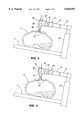
- FIG. 1is a perspective view of a patient's body on an operating table, with a laparoscopic lifting device in place within the body and secured to a lifting arm through means of a first embodiment of the present invention; a portion of the abdominal wall being broken away for purposes of illustration.
- FIG. 2is a enlarged view of the FIG. 1 first embodiment connection, shown with the lifting arm and lifting device in exploded perspective, illustrating the axes of pitch, roll and yaw movement.
- FIG. 3is a cross-sectional elevational view showing the lifting device of FIG. 1, with the arms of the lifting device bent downwardly as the result of the patient's obesity.
- FIG. 4is a cross-sectional elevational view similar to FIG. 1, showing the angle of the lifting device adjusted about the pitch axis to make room within the patient's body cavity, notwithstanding that the arms of the lifting device are bent due to the patient's obesity.
- FIG. 5is a cross-sectional elevational view showing the lifting device of FIG. 1 with the operating table rotated to maneuver the patient into a laterally tilted position and the organs within the patient's body shifted to one side as the result of gravity.
- FIG. 6is a cross-sectional elevational view corresponding to that of FIG. 5, illustrating the lifting device pivoted about the roll axis through means of the connection of the present invention to provide additional space above the organs which have shifted due to gravity.
- FIG. 7is a cross-sectional elevational view showing the lifting device of FIG. 1 with the arms of the device lifting in a condition generally parallel to the operating table.
- FIG. 8is a cross-sectional elevational view corresponding to FIG. 7, showing the lifting device tilted as the result of roll adjustment with the connection of the present invention to provide additional space to one side of the patient's body.
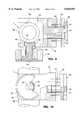
- FIG. 9is a cross-sectional view of the connection taken on the plane designated by line 9--9 of FIG. 2, illustrating the connection in the condition locked against pitch and roll movement.
- FIG. 10is an elevational view of the connection shown in FIG. 9, viewed from the bottom at 90° C. relative to the section of FIG. 9, with parts thereof broken away for purposes of illustration.
- FIG. 11is a cross-sectional view corresponding to that of FIG. 9, illustrating the connection in the condition released for pitch and roll movement.
- FIG. 12is a cross-sectional view taken on the plane designated by line 12--12 of FIG. 11.
- FIG. 13is an exploded perspective view similar to FIG. 12, illustrating a second embodiment of the connector.
- FIG. 14is an enlarged perspective view of the ratchet used in the second embodiment connector, with the cover of the ratchet removed.
- FIG. 15is an exploded perspective view similar to FIGS. 2 and 13, illustrating a third embodiment connector.
- FIG. 1illustrates the torso of a patient "P" supported on an operating table “T” during the course of laparoscopic surgery.
- the legs of the patient, designated “L”extend to the left, as shown in this figure.
- a small laparoscopic opening “O”is formed in the abdominal wall of the patient and a laparoscopic lifting instrument “I” is shown extending through this opening.
- the instrument “I”may be of the type shown in application Ser. No. 07/890,093.
- the abdominal wallis shown broken-away in FIG. 1 in order that the lifting arms 10 of the instrument may be seen, it should be understood that the opening shown is for illustrative purposes only and that no such opening is formed during laparoscopic surgery.
- the instrument “I”is supported on a mechanical lifting arm “A” disposed externally of the patient's body.
- the arm “A”has articulated sections 12 and 14 joined by an elbow-like joint 16 which provides a vertical hinge, while enabling lifting force to be transmitted from the section 12 to the section 14.
- the section 12is supported on a jack 18 mounted either to the operating room table "T", or a separate support stand.
- the jack 18may be powered up and down, as shown by the arrow lines in FIG.
- a mounting block 20is secured to the distal end of the section 14 for purposes of attaching the lifting arm "A" to the instrument "I.”
- the block 20is formed with a first tapered dovetail slot 22 engagable with a dovetail formed on the distal end of the arm section 14.
- Tapered dovetail slots 24, 26 and 28 spaced 90° C. from one anotherare formed in the sides of the block 20 for select engagement by a tapered dovetail 30 mounted to the instrument "I.”
- instrument "I”has an internal structure and mode of operation corresponding to that of application Ser. No. 07/890,033 and is mounted for rotational movement about a vertical "yaw” axis 32, it is also mounted for select rotational movement about a "pitch” axis 34 and a “roll” axis 36. Adjustment about the latter axes is provided through means of the connection of the present invention.
- FIG. 1The construction of the joint shown in FIG. 1, designated in its entirety by the letter “J” may best be seen from FIGS. 9-12.
- the outer housing 38 of the instrument "I”is mounted in a fork structure 40.
- the fork structure 40is mounted for rotation about the pitch axis 34 by a shaft 42 fixed to the fork structure and journaled within a bearing sleeve 44 fixed to the dovetail 30.
- the outer surface of the sleeve 44is formed with a longitudinally extending spline 46.
- the shaft 42is formed with a collar 48 having a longitudinally extending spline 50 complemental to the spline 46.
- An internally splined collar 52mates with and is slidably received on the splines 46 and 50 for movement between a position locking the shaft 42 and bearing sleeve 44 against relative rotational movement, as shown in FIG. 9, and a position releasing the shaft and sleeve for such relative movement, as shown in FIG. 11.
- a compression coil spring 54is interposed between the back of the dovetail 30 and the slidable collar 52 to normally urge the collar to the locked condition shown in FIG. 9.
- the instrument “I”is pivotally mounted in the fork structure 40 for movement about the roll axis 36 by a pin 56 journaled in one side of the fork structure and a sleeve 58 journaled in the other side of the fork structure.
- the pin 56 and sleeve 58are longitudinally aligned and fixed relative to the housing 38 of the instrument "I.”
- the sleeve 58is provided with a longitudinally extending internal spline 60. Select locking of the sleeve 58 and attached instrument "I" is provided by engaging the spline 60 with the splined head 62 of a locking bolt 64 slidably carried by the fork structure 40. The bolt 64 is received within a collar 66 fixed to the fork structure 40. A compression coil spring 68 normally biases the splined head 62 into engagement with the spine 60 of the sleeve 58. Select retraction of the bolt to the disengaged position is provided by an enlarged manually grippable knob 70 secured to the bolt. A key 72 carried by the collar 66 slidably engages a keyway 74 within the bolt 64 to hold the bolt against rotation relative to the collar.
- the splined head 62 of the bolt 64is engaged with the spine 60 of the sleeve 58 to lock the instrument "I" against rotation about the roll axis 36.
- the spring 68normally biases the head 62 into this condition. Release of the instrument for rotation about the roll axis is provided by manually withdrawing the knob 70. Such withdrawal removes the splined head 62 from engagement with the spline 60 of the sleeve 58.
- Adjustment of the pitch of the lifting instrumentwill be useful in at least three instances, namely:
- FIG. 3Such a condition is shown in FIG. 3 where the legs 10 are bent downwardly and, thus, may not provide the desired degree of exposure within the body cavity.
- the legscan be brought up to provide more exposure for the laparoscopic procedure.
- Adjustment about the roll axisis also useful in a number of instances, for example:
- FIG. 5where the table has been shifted.
- the surgeoncan return the lifting device to the desired angle, as shown in FIG. 6.
- the tablecould likewise be rotated to maneuver the patient into a laterally tilted position, or reverse laterally tilted position, and that could be compensated by pitch adjustment.
- FIG. 7shows the internal exposure which would be provided by movement of the lifting device vertically, without roll adjustment.
- Pitch and roll adjustment with the embodiment of FIGS. 1, 2 and 9-12is selectively effected by simply moving either the collar 52 or knob 70 to the position releasing the splines members associated therewith for rotation relative to one another and then moving the instrument to the desired position Once in the desired position, the sleeve 52 or knob 70 is released to reengage the splines, thus locking the instrument in the adjusted condition of pitch or roll.
- FIGS. 13 and 14show a second embodiment wherein pitch and roll adjustment is achieved similarly to the aforedescribed adjustment, except that selective locking is provided by ratchet mechanisms.
- the fork 40is mounted for rotation about the pitch axis 34 and carries the instrument "I" for rotation about the roll axis 36.
- ratchet mechanisms 76are provided, one for yaw adjustment and one for pitch adjustment.
- the ratchet mechanismseach comprise a shaft 78 rotatable about the axis therefore and having fixed thereto a ratchet wheel 80.
- the wheel 80is mounted within a housing 82 having a chamber therein for receipt of the ratchet mechanism.
- the ratchet mechanismalso includes pawls 86 and 88 pivotally mounted to the housing within the chamber 84 and an operating lever 90 supported between the pawls to selectively move one or the other of the pawls out of engagement with the ratchet wheel while the other is moved into engagement with the wheel.
- the ratchet mechanism for pitch adjustmentis designated by the numeral 76a and the ratchet mechanism for roll adjustment is designated by the numeral 76b.
- These mechanismscorrespond to the aforedescribed mechanism 76.
- the housing of the ratchet mechanism 76ais fixed to the bight portion of the fork structure 40.
- the shaft 78 of the mechanism 76ais fixed to the dovetail 30.
- the housing of the ratchet mechanism 76bis fixed to one leg of the fork structure 40 and the shaft 78 of this mechanism extends coaxially with the roll axis 36 for rotation within the leg of the structure 40 on which the mechanism is mounted.
- the distal end of the shaft 78 for the mechanism 76bis fixed to the housing 38 for the instrument "I,” much in the same way that the sleeve 62 is fixed to the housing 38.
- FIG. 13 and 14 embodimentmay be used in the same way as the embodiment of FIGS. 1, 2 and 9-12. As compared to the latter embodiment, however, the FIG. 13 and 14 embodiment has the advantage that the surgeon need only set the ratchet mechanisms with the operating levers therefor and then move the lifting instrument to the desired pitch and yaw angles. Upon release after such movement, the ratchet mechanism will automatically lock the instrument against return to the nonadjusted condition.
- FIG. 15illustrates a simplified ball and socket mechanism for providing pitch and roll adjustment. Elements of this embodiment corresponding to those of the previous embodiments are designated by like numerals.
- the instrument "I"is mounted within a ball 92. Although the instrument may be mounted for free movement relative to the ball about the yaw axis, such movement is not necessary because the ball is free to rotate in all directions.
- the ballis rotatably received within a spherical collar 94 fixed to the dovetail 30 by a shaft 96.
- a set screw 98extends threadably through the collar for select engagement with the ball 92 to lock the ball against rotational movement relative to the collar.
- FIG. 15 embodimentmay be used in the same way as the aforedescribed embodiments. In the case of FIG. 15, it is simply necessary to release the set screw to provide for pitch and roll adjustment and then to tighten the screw when the desired adjusted condition is achieved.
- the jack 18may be selectively operated with all embodiments of the present invention to achieve desired lifting, or relaxation of lifting. To ease the pitch and roll adjustment, it is likely the surgeon would effect adjustment with the jack in a condition relaxing the arms 10 from significant lifting and then, once adjustment is achieved, activate the jack to elevate the wall of the body cavity being worked.
Landscapes
- Health & Medical Sciences (AREA)
- Surgery (AREA)
- Life Sciences & Earth Sciences (AREA)
- Heart & Thoracic Surgery (AREA)
- Engineering & Computer Science (AREA)
- Biomedical Technology (AREA)
- Nuclear Medicine, Radiotherapy & Molecular Imaging (AREA)
- Medical Informatics (AREA)
- Molecular Biology (AREA)
- Animal Behavior & Ethology (AREA)
- General Health & Medical Sciences (AREA)
- Public Health (AREA)
- Veterinary Medicine (AREA)
- Pathology (AREA)
- Oral & Maxillofacial Surgery (AREA)
- Surgical Instruments (AREA)
Abstract
Description
Claims (4)
Priority Applications (1)
| Application Number | Priority Date | Filing Date | Title |
|---|---|---|---|
| US08/774,995US5820555A (en) | 1991-05-29 | 1996-12-27 | Method for selectively creating and altering the shape of a body cavity |
Applications Claiming Priority (4)
| Application Number | Priority Date | Filing Date | Title |
|---|---|---|---|
| US70678191A | 1991-05-29 | 1991-05-29 | |
| US08/062,707US5520609A (en) | 1991-05-29 | 1993-05-18 | Apparatus and method for peritoneal retraction |
| US33906894A | 1994-11-14 | 1994-11-14 | |
| US08/774,995US5820555A (en) | 1991-05-29 | 1996-12-27 | Method for selectively creating and altering the shape of a body cavity |
Related Parent Applications (1)
| Application Number | Title | Priority Date | Filing Date |
|---|---|---|---|
| US33906894AContinuation | 1991-05-29 | 1994-11-14 |
Publications (1)
| Publication Number | Publication Date |
|---|---|
| US5820555Atrue US5820555A (en) | 1998-10-13 |
Family
ID=27370362
Family Applications (1)
| Application Number | Title | Priority Date | Filing Date |
|---|---|---|---|
| US08/774,995Expired - LifetimeUS5820555A (en) | 1991-05-29 | 1996-12-27 | Method for selectively creating and altering the shape of a body cavity |
Country Status (1)
| Country | Link |
|---|---|
| US (1) | US5820555A (en) |
Cited By (60)
| Publication number | Priority date | Publication date | Assignee | Title |
|---|---|---|---|---|
| RU2170058C2 (en)* | 1999-08-27 | 2001-07-10 | Восканян Сергей Эдуардович | Device for elevating anterior abdominal wall |
| US6338738B1 (en) | 1999-08-31 | 2002-01-15 | Edwards Lifesciences Corp. | Device and method for stabilizing cardiac tissue |
| US6464690B1 (en) | 2000-10-11 | 2002-10-15 | Popcab, Llc | Port off-pump beating heart coronary artery bypass heart stabilization system |
| US6503245B2 (en) | 2000-10-11 | 2003-01-07 | Medcanica, Inc. | Method of performing port off-pump beating heart coronary artery bypass surgery |
| US20030036677A1 (en)* | 1996-02-20 | 2003-02-20 | Taylor Charles S. | Surgical devices for imposing a negative pressure to stabilize the cardiac tissue during surgery |
| US6582420B2 (en) | 2000-10-11 | 2003-06-24 | Popcab, Llc | Intercostal lockable directable port device |
| US6592573B2 (en) | 2000-10-11 | 2003-07-15 | Popcab, Llc | Through-port heart stabilization system |
| US6602189B1 (en)* | 1996-02-20 | 2003-08-05 | Cardiothoracic Systems, Inc. | Access platform for internal mammary dissection |
| WO2005089654A1 (en)* | 2004-03-23 | 2005-09-29 | Atropos Limited | A wound retractor device |
| WO2007054156A1 (en) | 2005-11-11 | 2007-05-18 | Hans Haindl | Device for supporting the abdominal wall in relation to underlying organs in minimally invasive surgery |
| US7219671B2 (en) | 1995-04-10 | 2007-05-22 | Cardiothoracic Systems, Inc. | Method for coronary artery bypass |
| EP1790290A3 (en)* | 2005-11-28 | 2007-07-18 | Cefla Societa' Cooperativa | Unit for acquiring dental radiographic images |
| US20070239108A1 (en)* | 2006-03-13 | 2007-10-11 | Applied Medical Resources Corporation | Balloon trocar |
| US7300399B2 (en) | 1998-12-01 | 2007-11-27 | Atropos Limited | Surgical device for retracting and/or sealing an incision |
| US20080135663A1 (en)* | 2006-11-03 | 2008-06-12 | Quantum Corporation | Tape leader buckler having increased hooking area |
| US7540839B2 (en) | 1999-10-14 | 2009-06-02 | Atropos Limited | Wound retractor |
| US7559893B2 (en) | 1998-12-01 | 2009-07-14 | Atropos Limited | Wound retractor device |
| RU2372045C1 (en)* | 2008-04-28 | 2009-11-10 | Государственное образовательное учреждение высшего профессионального образования Смоленская государственная медицинская академия федерального агентства по здравоохранению и социальному развитию | Fan-shaped laparolift |
| RU2397728C1 (en)* | 2009-01-11 | 2010-08-27 | Валентин Иванович Закусило | Device for laparolifting at laparoscopic operations |
| US7867164B2 (en) | 1999-10-14 | 2011-01-11 | Atropos Limited | Wound retractor system |
| US20110028791A1 (en)* | 2009-07-28 | 2011-02-03 | Marino James F | Arcuate surgical guidance system and methods |
| US8016755B2 (en) | 2000-10-19 | 2011-09-13 | Applied Medical Resources Corporation | Surgical access apparatus and method |
| US8021296B2 (en) | 1999-12-01 | 2011-09-20 | Atropos Limited | Wound retractor |
| US8083664B2 (en) | 2005-05-25 | 2011-12-27 | Maquet Cardiovascular Llc | Surgical stabilizers and methods for use in reduced-access surgical sites |
| WO2012010910A1 (en)* | 2010-07-23 | 2012-01-26 | The University Of Leeds | Surgical retraction device and procedure |
| US8109873B2 (en) | 2007-05-11 | 2012-02-07 | Applied Medical Resources Corporation | Surgical retractor with gel pad |
| US8157835B2 (en) | 2001-08-14 | 2012-04-17 | Applied Medical Resouces Corporation | Access sealing apparatus and method |
| US8187177B2 (en) | 2003-09-17 | 2012-05-29 | Applied Medical Resources Corporation | Surgical instrument access device |
| US8187178B2 (en) | 2007-06-05 | 2012-05-29 | Atropos Limited | Instrument access device |
| US8226552B2 (en) | 2007-05-11 | 2012-07-24 | Applied Medical Resources Corporation | Surgical retractor |
| US8235054B2 (en) | 2002-06-05 | 2012-08-07 | Applied Medical Resources Corporation | Wound retractor |
| US8262568B2 (en) | 2008-10-13 | 2012-09-11 | Applied Medical Resources Corporation | Single port access system |
| US8267858B2 (en) | 2005-10-14 | 2012-09-18 | Applied Medical Resources Corporation | Wound retractor with gel cap |
| US8287503B2 (en) | 2006-03-13 | 2012-10-16 | Applied Medical Resources Corporation | Balloon trocar |
| US8343047B2 (en) | 2008-01-22 | 2013-01-01 | Applied Medical Resources Corporation | Surgical instrument access device |
| US8375955B2 (en) | 2009-02-06 | 2013-02-19 | Atropos Limited | Surgical procedure |
| US8388526B2 (en) | 2001-10-20 | 2013-03-05 | Applied Medical Resources Corporation | Wound retraction apparatus and method |
| US8657740B2 (en) | 2007-06-05 | 2014-02-25 | Atropos Limited | Instrument access device |
| US8703034B2 (en) | 2001-08-14 | 2014-04-22 | Applied Medical Resources Corporation | Method of making a tack-free gel |
| US8734336B2 (en) | 1998-12-01 | 2014-05-27 | Atropos Limited | Wound retractor device |
| US8758236B2 (en) | 2011-05-10 | 2014-06-24 | Applied Medical Resources Corporation | Wound retractor |
| CN103876792A (en)* | 2012-12-24 | 2014-06-25 | 孙墨 | Endoscope retractor of minimally invasive surgery |
| US8888692B1 (en) | 2011-08-26 | 2014-11-18 | Applied Medical Resources Corporation | Trocar cannula assembly and method of manufacture |
| US8932214B2 (en) | 2003-02-25 | 2015-01-13 | Applied Medical Resources Corporation | Surgical access system |
| US8986202B2 (en) | 1999-10-14 | 2015-03-24 | Atropos Limited | Retractor |
| US9271753B2 (en) | 2002-08-08 | 2016-03-01 | Atropos Limited | Surgical device |
| US9289200B2 (en) | 2010-10-01 | 2016-03-22 | Applied Medical Resources Corporation | Natural orifice surgery system |
| US9289115B2 (en) | 2010-10-01 | 2016-03-22 | Applied Medical Resources Corporation | Natural orifice surgery system |
| US9351759B2 (en) | 2007-06-05 | 2016-05-31 | Atropos Limited | Instrument access device |
| US9522265B2 (en) | 2013-03-15 | 2016-12-20 | Applied Medical Resources Corporation | Trocar cannula assembly with low profile insertion configuration and method of manufacture |
| US9642608B2 (en) | 2014-07-18 | 2017-05-09 | Applied Medical Resources Corporation | Gels having permanent tack free coatings and method of manufacture |
| US20170231612A1 (en)* | 2016-02-15 | 2017-08-17 | Zafer Termanini | Femoral elevator device |
| US9757110B2 (en) | 1998-12-01 | 2017-09-12 | Atropos Limited | Instrument access device |
| US9949730B2 (en) | 2014-11-25 | 2018-04-24 | Applied Medical Resources Corporation | Circumferential wound retraction with support and guidance structures |
| CN108030522A (en)* | 2017-12-21 | 2018-05-15 | 辽宁省肿瘤医院 | A kind of multi-functional retractor of operation on pelvis |
| US10172641B2 (en) | 2014-08-15 | 2019-01-08 | Applied Medical Resources Corporation | Natural orifice surgery system |
| US10368908B2 (en) | 2015-09-15 | 2019-08-06 | Applied Medical Resources Corporation | Surgical robotic access system |
| US10575840B2 (en) | 2015-10-07 | 2020-03-03 | Applied Medical Resources Corporation | Wound retractor with multi-segment outer ring |
| US10674896B2 (en) | 2016-09-12 | 2020-06-09 | Applied Medical Resources Corporation | Surgical robotic access system for irregularly shaped robotic actuators and associated robotic surgical instruments |
| US11471142B2 (en) | 2013-03-15 | 2022-10-18 | Applied Medical Resources Corporation | Mechanical gel surgical access device |
Citations (10)
| Publication number | Priority date | Publication date | Assignee | Title |
|---|---|---|---|---|
| US3638973A (en)* | 1969-06-04 | 1972-02-01 | Charles Ellis Poletti | Joint means for use in work supporting arm |
| US4143652A (en)* | 1976-01-29 | 1979-03-13 | Hans Meier | Surgical retaining device |
| DE2923105A1 (en)* | 1979-06-07 | 1980-12-11 | Storz Karl | Gall stone surgery instrument - has trocar sleeve insert with external elements increasing frictional resistance to axial movement |
| US4622955A (en)* | 1985-09-05 | 1986-11-18 | Mehdi Fakhrai | Surgical retractor for dissection of internal mammary artery |
| US4949707A (en)* | 1984-11-08 | 1990-08-21 | Minnesota Scientific, Inc. | Retractor apparatus |
| EP0415417A2 (en)* | 1989-09-01 | 1991-03-06 | Andronic Devices Ltd. | Holder for surgical instruments |
| WO1991014392A1 (en)* | 1990-03-20 | 1991-10-03 | Philippe Mouret | Instrument for performing medical or surgical operations by laparoscopy or coeliscopy |
| US5372147A (en)* | 1992-06-16 | 1994-12-13 | Origin Medsystems, Inc. | Peritoneal distension robotic arm |
| US5415159A (en)* | 1993-08-18 | 1995-05-16 | Ethicon, Inc. | Support structure for abdominal lift |
| US5441042A (en)* | 1991-08-05 | 1995-08-15 | Putman; John M. | Endoscope instrument holder |
- 1996
- 1996-12-27USUS08/774,995patent/US5820555A/ennot_activeExpired - Lifetime
Patent Citations (10)
| Publication number | Priority date | Publication date | Assignee | Title |
|---|---|---|---|---|
| US3638973A (en)* | 1969-06-04 | 1972-02-01 | Charles Ellis Poletti | Joint means for use in work supporting arm |
| US4143652A (en)* | 1976-01-29 | 1979-03-13 | Hans Meier | Surgical retaining device |
| DE2923105A1 (en)* | 1979-06-07 | 1980-12-11 | Storz Karl | Gall stone surgery instrument - has trocar sleeve insert with external elements increasing frictional resistance to axial movement |
| US4949707A (en)* | 1984-11-08 | 1990-08-21 | Minnesota Scientific, Inc. | Retractor apparatus |
| US4622955A (en)* | 1985-09-05 | 1986-11-18 | Mehdi Fakhrai | Surgical retractor for dissection of internal mammary artery |
| EP0415417A2 (en)* | 1989-09-01 | 1991-03-06 | Andronic Devices Ltd. | Holder for surgical instruments |
| WO1991014392A1 (en)* | 1990-03-20 | 1991-10-03 | Philippe Mouret | Instrument for performing medical or surgical operations by laparoscopy or coeliscopy |
| US5441042A (en)* | 1991-08-05 | 1995-08-15 | Putman; John M. | Endoscope instrument holder |
| US5372147A (en)* | 1992-06-16 | 1994-12-13 | Origin Medsystems, Inc. | Peritoneal distension robotic arm |
| US5415159A (en)* | 1993-08-18 | 1995-05-16 | Ethicon, Inc. | Support structure for abdominal lift |
Cited By (135)
| Publication number | Priority date | Publication date | Assignee | Title |
|---|---|---|---|---|
| US7219671B2 (en) | 1995-04-10 | 2007-05-22 | Cardiothoracic Systems, Inc. | Method for coronary artery bypass |
| US6602189B1 (en)* | 1996-02-20 | 2003-08-05 | Cardiothoracic Systems, Inc. | Access platform for internal mammary dissection |
| US7288065B1 (en) | 1996-02-20 | 2007-10-30 | Cardiothoracic System, Inc. | Access platform for internal mammary dissection |
| US8382654B2 (en) | 1996-02-20 | 2013-02-26 | Maquet Cardiovascular Llc | Surgical devices for imposing a negative pressure to stabilize the cardiac tissue during surgery |
| US20030036677A1 (en)* | 1996-02-20 | 2003-02-20 | Taylor Charles S. | Surgical devices for imposing a negative pressure to stabilize the cardiac tissue during surgery |
| US7335158B2 (en) | 1996-02-20 | 2008-02-26 | Cardiothoracic Systems, Inc. | Surgical devices for imposing a negative pressure to stabilize the cardiac tissue during surgery |
| US7909846B1 (en) | 1996-02-20 | 2011-03-22 | Maquet Cardiovascular Llc | Access platform for internal mammary dissection |
| US10278688B2 (en) | 1998-12-01 | 2019-05-07 | Atropos Limited | Wound retractor device |
| US8734336B2 (en) | 1998-12-01 | 2014-05-27 | Atropos Limited | Wound retractor device |
| US9757110B2 (en) | 1998-12-01 | 2017-09-12 | Atropos Limited | Instrument access device |
| US9095300B2 (en) | 1998-12-01 | 2015-08-04 | Atropos Limited | Wound retractor device |
| US7559893B2 (en) | 1998-12-01 | 2009-07-14 | Atropos Limited | Wound retractor device |
| US9700296B2 (en) | 1998-12-01 | 2017-07-11 | Atropos Limited | Wound retractor device |
| US8317691B2 (en) | 1998-12-01 | 2012-11-27 | Atropos Limited | Wound retractor device |
| US7300399B2 (en) | 1998-12-01 | 2007-11-27 | Atropos Limited | Surgical device for retracting and/or sealing an incision |
| RU2170058C2 (en)* | 1999-08-27 | 2001-07-10 | Восканян Сергей Эдуардович | Device for elevating anterior abdominal wall |
| US6338738B1 (en) | 1999-08-31 | 2002-01-15 | Edwards Lifesciences Corp. | Device and method for stabilizing cardiac tissue |
| US8740785B2 (en) | 1999-10-14 | 2014-06-03 | Atropos Limited | Wound retractor system |
| US9277908B2 (en) | 1999-10-14 | 2016-03-08 | Atropos Limited | Retractor |
| US7540839B2 (en) | 1999-10-14 | 2009-06-02 | Atropos Limited | Wound retractor |
| US7867164B2 (en) | 1999-10-14 | 2011-01-11 | Atropos Limited | Wound retractor system |
| US8986202B2 (en) | 1999-10-14 | 2015-03-24 | Atropos Limited | Retractor |
| US8021296B2 (en) | 1999-12-01 | 2011-09-20 | Atropos Limited | Wound retractor |
| US8657741B2 (en) | 1999-12-01 | 2014-02-25 | Atropos Limited | Wound retractor |
| US6464690B1 (en) | 2000-10-11 | 2002-10-15 | Popcab, Llc | Port off-pump beating heart coronary artery bypass heart stabilization system |
| US6503245B2 (en) | 2000-10-11 | 2003-01-07 | Medcanica, Inc. | Method of performing port off-pump beating heart coronary artery bypass surgery |
| US6582420B2 (en) | 2000-10-11 | 2003-06-24 | Popcab, Llc | Intercostal lockable directable port device |
| US6592573B2 (en) | 2000-10-11 | 2003-07-15 | Popcab, Llc | Through-port heart stabilization system |
| US8105234B2 (en) | 2000-10-19 | 2012-01-31 | Applied Medical Resources Corporation | Surgical access apparatus and method |
| US8016755B2 (en) | 2000-10-19 | 2011-09-13 | Applied Medical Resources Corporation | Surgical access apparatus and method |
| US8070676B2 (en) | 2000-10-19 | 2011-12-06 | Applied Medical Resources Corporation | Surgical access apparatus and method |
| US8496581B2 (en) | 2000-10-19 | 2013-07-30 | Applied Medical Resources Corporation | Surgical access apparatus and method |
| US8672839B2 (en) | 2000-10-19 | 2014-03-18 | Applied Medical Resource Corporation | Surgical access apparatus and method |
| US8911366B2 (en) | 2000-10-19 | 2014-12-16 | Applied Medical Resources Corporation | Surgical access apparatus and method |
| US9878140B2 (en) | 2001-08-14 | 2018-01-30 | Applied Medical Resources Corporation | Access sealing apparatus and method |
| US8870904B2 (en) | 2001-08-14 | 2014-10-28 | Applied Medical Resources Corporation | Access sealing apparatus and method |
| US9669153B2 (en) | 2001-08-14 | 2017-06-06 | Applied Medical Resources Corporation | Method of manufacturing a tack-free gel for a surgical device |
| US8157835B2 (en) | 2001-08-14 | 2012-04-17 | Applied Medical Resouces Corporation | Access sealing apparatus and method |
| US8703034B2 (en) | 2001-08-14 | 2014-04-22 | Applied Medical Resources Corporation | Method of making a tack-free gel |
| US8388526B2 (en) | 2001-10-20 | 2013-03-05 | Applied Medical Resources Corporation | Wound retraction apparatus and method |
| US10507017B2 (en) | 2002-06-05 | 2019-12-17 | Applied Medical Resources Corporation | Wound retractor |
| US8235054B2 (en) | 2002-06-05 | 2012-08-07 | Applied Medical Resources Corporation | Wound retractor |
| US9561024B2 (en) | 2002-06-05 | 2017-02-07 | Applied Medical Resources Corporation | Wound retractor |
| US8973583B2 (en) | 2002-06-05 | 2015-03-10 | Applied Medical Resources Corporation | Wound retractor |
| US9737335B2 (en) | 2002-08-08 | 2017-08-22 | Atropos Limited | Device |
| US10405883B2 (en) | 2002-08-08 | 2019-09-10 | Atropos Limited | Surgical device |
| US9271753B2 (en) | 2002-08-08 | 2016-03-01 | Atropos Limited | Surgical device |
| US9307976B2 (en) | 2002-10-04 | 2016-04-12 | Atropos Limited | Wound retractor |
| US9295459B2 (en) | 2003-02-25 | 2016-03-29 | Applied Medical Resources Corporation | Surgical access system |
| US8932214B2 (en) | 2003-02-25 | 2015-01-13 | Applied Medical Resources Corporation | Surgical access system |
| US8187177B2 (en) | 2003-09-17 | 2012-05-29 | Applied Medical Resources Corporation | Surgical instrument access device |
| US8357086B2 (en) | 2003-09-17 | 2013-01-22 | Applied Medical Resources Corporation | Surgical instrument access device |
| WO2005089654A1 (en)* | 2004-03-23 | 2005-09-29 | Atropos Limited | A wound retractor device |
| US8083664B2 (en) | 2005-05-25 | 2011-12-27 | Maquet Cardiovascular Llc | Surgical stabilizers and methods for use in reduced-access surgical sites |
| US9649102B2 (en) | 2005-10-14 | 2017-05-16 | Applied Medical Resources Corporation | Wound retractor with split hoops |
| US8414487B2 (en) | 2005-10-14 | 2013-04-09 | Applied Medical Resources Corporation | Circular surgical retractor |
| US8313431B2 (en) | 2005-10-14 | 2012-11-20 | Applied Medical Resources Corporation | Split hoop wound retractor |
| US8647265B2 (en) | 2005-10-14 | 2014-02-11 | Applied Medical Resources Corporation | Hand access laparoscopic device |
| US9474519B2 (en) | 2005-10-14 | 2016-10-25 | Applied Medical Resources Corporation | Hand access laparoscopic device |
| US8308639B2 (en) | 2005-10-14 | 2012-11-13 | Applied Medical Resources Corporation | Split hoop wound retractor with gel pad |
| US8267858B2 (en) | 2005-10-14 | 2012-09-18 | Applied Medical Resources Corporation | Wound retractor with gel cap |
| US9017254B2 (en) | 2005-10-14 | 2015-04-28 | Applied Medical Resources Corporation | Hand access laparoscopic device |
| US9101354B2 (en) | 2005-10-14 | 2015-08-11 | Applied Medical Resources Corporation | Wound retractor with gel cap |
| US20090069627A1 (en)* | 2005-11-11 | 2009-03-12 | Hans Haindl | Device for supporting the abdominal wall relative to underlying organs during minimally invasive surgery |
| DE102005053831A1 (en)* | 2005-11-11 | 2007-05-24 | Haindl, Hans, Dr.med. Dipl.-Ing. | Device for supporting the abdominal wall against underlying organs in minimally invasive surgery |
| WO2007054156A1 (en) | 2005-11-11 | 2007-05-18 | Hans Haindl | Device for supporting the abdominal wall in relation to underlying organs in minimally invasive surgery |
| US7429130B2 (en) | 2005-11-28 | 2008-09-30 | Cefla Societa Cooperative | Unit for acquiring dental radiographic images |
| US20070237292A1 (en)* | 2005-11-28 | 2007-10-11 | Stefano Malucelli | Unit for acquiring dental radiographic images |
| EP1790290A3 (en)* | 2005-11-28 | 2007-07-18 | Cefla Societa' Cooperativa | Unit for acquiring dental radiographic images |
| US20070239108A1 (en)* | 2006-03-13 | 2007-10-11 | Applied Medical Resources Corporation | Balloon trocar |
| US9259238B2 (en) | 2006-03-13 | 2016-02-16 | Applied Medical Resources Corporation | Balloon trocar |
| US8147453B2 (en) | 2006-03-13 | 2012-04-03 | Applied Medical Resources Corporation | Balloon trocar |
| US8939946B2 (en) | 2006-03-13 | 2015-01-27 | Applied Medical Resources Corporation | Balloon trocar |
| US8287503B2 (en) | 2006-03-13 | 2012-10-16 | Applied Medical Resources Corporation | Balloon trocar |
| US20080135663A1 (en)* | 2006-11-03 | 2008-06-12 | Quantum Corporation | Tape leader buckler having increased hooking area |
| US8109873B2 (en) | 2007-05-11 | 2012-02-07 | Applied Medical Resources Corporation | Surgical retractor with gel pad |
| US8961410B2 (en) | 2007-05-11 | 2015-02-24 | Applied Medical Resources Corporation | Surgical retractor with gel pad |
| US8226552B2 (en) | 2007-05-11 | 2012-07-24 | Applied Medical Resources Corporation | Surgical retractor |
| US9351759B2 (en) | 2007-06-05 | 2016-05-31 | Atropos Limited | Instrument access device |
| US10537360B2 (en) | 2007-06-05 | 2020-01-21 | Atropos Limited | Instrument access device |
| US10321934B2 (en) | 2007-06-05 | 2019-06-18 | Atropos Limited | Instrument access device |
| US8187178B2 (en) | 2007-06-05 | 2012-05-29 | Atropos Limited | Instrument access device |
| US8657740B2 (en) | 2007-06-05 | 2014-02-25 | Atropos Limited | Instrument access device |
| US9408597B2 (en) | 2007-06-05 | 2016-08-09 | Atropos Limited | Instrument access device |
| US8343047B2 (en) | 2008-01-22 | 2013-01-01 | Applied Medical Resources Corporation | Surgical instrument access device |
| RU2372045C1 (en)* | 2008-04-28 | 2009-11-10 | Государственное образовательное учреждение высшего профессионального образования Смоленская государственная медицинская академия федерального агентства по здравоохранению и социальному развитию | Fan-shaped laparolift |
| US8262568B2 (en) | 2008-10-13 | 2012-09-11 | Applied Medical Resources Corporation | Single port access system |
| US8721537B2 (en) | 2008-10-13 | 2014-05-13 | Applied Medical Resources Corporation | Single port access system |
| US8480575B2 (en) | 2008-10-13 | 2013-07-09 | Applied Medical Resources Corporation | Single port access system |
| US8894571B2 (en) | 2008-10-13 | 2014-11-25 | Applied Medical Resources Corporation | Single port access system |
| RU2397728C1 (en)* | 2009-01-11 | 2010-08-27 | Валентин Иванович Закусило | Device for laparolifting at laparoscopic operations |
| US8375955B2 (en) | 2009-02-06 | 2013-02-19 | Atropos Limited | Surgical procedure |
| US20110028791A1 (en)* | 2009-07-28 | 2011-02-03 | Marino James F | Arcuate surgical guidance system and methods |
| US8721536B2 (en)* | 2009-07-28 | 2014-05-13 | Trinity Orthopedics, Llc | Arcuate surgical guidance system and methods |
| WO2012010910A1 (en)* | 2010-07-23 | 2012-01-26 | The University Of Leeds | Surgical retraction device and procedure |
| US9289200B2 (en) | 2010-10-01 | 2016-03-22 | Applied Medical Resources Corporation | Natural orifice surgery system |
| US12089872B2 (en) | 2010-10-01 | 2024-09-17 | Applied Medical Resources Corporation | Natural orifice surgery system |
| US9289115B2 (en) | 2010-10-01 | 2016-03-22 | Applied Medical Resources Corporation | Natural orifice surgery system |
| US10376282B2 (en) | 2010-10-01 | 2019-08-13 | Applied Medical Resources Corporation | Natural orifice surgery system |
| US11123102B2 (en) | 2010-10-01 | 2021-09-21 | Applied Medical Resources Corporation | Natural orifice surgery system |
| US10271875B2 (en) | 2010-10-01 | 2019-04-30 | Applied Medical Resources Corporation | Natural orifice surgery system |
| US9872702B2 (en) | 2010-10-01 | 2018-01-23 | Applied Medical Resources Corporation | Natural orifice surgery system |
| US8758236B2 (en) | 2011-05-10 | 2014-06-24 | Applied Medical Resources Corporation | Wound retractor |
| US9192366B2 (en) | 2011-05-10 | 2015-11-24 | Applied Medical Resources Corporation | Wound retractor |
| US9307975B2 (en) | 2011-05-10 | 2016-04-12 | Applied Medical Resources Corporation | Wound retractor |
| US9241697B2 (en) | 2011-05-10 | 2016-01-26 | Applied Medical Resources Corporation | Wound retractor |
| US11058407B2 (en) | 2011-08-26 | 2021-07-13 | Applied Medical Resources Corporation | Trocar cannula assembly and method of manufacture |
| US9655607B2 (en) | 2011-08-26 | 2017-05-23 | Applied Medical Resources Corporation | Trocar cannula assembly and method of manufacture |
| US8888692B1 (en) | 2011-08-26 | 2014-11-18 | Applied Medical Resources Corporation | Trocar cannula assembly and method of manufacture |
| US10357234B2 (en) | 2011-08-26 | 2019-07-23 | Applied Medical Resources Corporation | Trocar cannula assembly and method of manufacture |
| CN103876792A (en)* | 2012-12-24 | 2014-06-25 | 孙墨 | Endoscope retractor of minimally invasive surgery |
| US11471142B2 (en) | 2013-03-15 | 2022-10-18 | Applied Medical Resources Corporation | Mechanical gel surgical access device |
| US10420584B2 (en) | 2013-03-15 | 2019-09-24 | Applied Medical Resources Corporation | Trocar cannula assembly with low profile insertion configuration and method of manufacture |
| US11382659B2 (en) | 2013-03-15 | 2022-07-12 | Applied Medical Resources Corporation | Trocar cannula assembly with low profile insertion configuration and method of manufacture |
| US12185975B2 (en) | 2013-03-15 | 2025-01-07 | Applied Medical Resources Corporation | Trocar cannula assembly with low profile insertion configuration and method of manufacture |
| US9522265B2 (en) | 2013-03-15 | 2016-12-20 | Applied Medical Resources Corporation | Trocar cannula assembly with low profile insertion configuration and method of manufacture |
| US9642608B2 (en) | 2014-07-18 | 2017-05-09 | Applied Medical Resources Corporation | Gels having permanent tack free coatings and method of manufacture |
| US10172641B2 (en) | 2014-08-15 | 2019-01-08 | Applied Medical Resources Corporation | Natural orifice surgery system |
| US12262914B2 (en) | 2014-08-15 | 2025-04-01 | Applied Medical Resources Corporation | Natural orifice surgery system |
| US11583316B2 (en) | 2014-08-15 | 2023-02-21 | Applied Medical Resources Corporation | Natural orifice surgery system |
| US10952768B2 (en) | 2014-08-15 | 2021-03-23 | Applied Medical Resources Corporation | Natural orifice surgery system |
| US9949730B2 (en) | 2014-11-25 | 2018-04-24 | Applied Medical Resources Corporation | Circumferential wound retraction with support and guidance structures |
| US10368908B2 (en) | 2015-09-15 | 2019-08-06 | Applied Medical Resources Corporation | Surgical robotic access system |
| US11883068B2 (en) | 2015-09-15 | 2024-01-30 | Applied Medical Resources Corporation | Surgical robotic access system |
| US11382658B2 (en) | 2015-09-15 | 2022-07-12 | Applied Medical Resources Corporation | Surgical robotic access system |
| US10575840B2 (en) | 2015-10-07 | 2020-03-03 | Applied Medical Resources Corporation | Wound retractor with multi-segment outer ring |
| US12185932B2 (en) | 2015-10-07 | 2025-01-07 | Applied Medical Resources Corporation | Wound retractor with multi-segment outer ring |
| US11602338B2 (en) | 2015-10-07 | 2023-03-14 | Applied Medical Resources Corporation | Wound retractor with multi-segment outer ring |
| EP3397230A1 (en)* | 2016-02-15 | 2018-11-07 | Joint Innovation Technology, LLC | Femoral elevator device |
| US20170231612A1 (en)* | 2016-02-15 | 2017-08-17 | Zafer Termanini | Femoral elevator device |
| US11627867B2 (en) | 2016-09-12 | 2023-04-18 | Applied Medical Resources Corporation | Surgical robotic access system for irregularly shaped robotic actuators and associated robotic surgical instruments |
| US11992184B2 (en) | 2016-09-12 | 2024-05-28 | Applied Medical Resources Corporation | Surgical robotic access system for irregularly shaped robotic actuators and associated robotic surgical instruments |
| US10674896B2 (en) | 2016-09-12 | 2020-06-09 | Applied Medical Resources Corporation | Surgical robotic access system for irregularly shaped robotic actuators and associated robotic surgical instruments |
| CN108030522B (en)* | 2017-12-21 | 2020-07-10 | 辽宁省肿瘤医院 | A multifunctional retractor for pelvic surgery |
| CN108030522A (en)* | 2017-12-21 | 2018-05-15 | 辽宁省肿瘤医院 | A kind of multi-functional retractor of operation on pelvis |
Similar Documents
| Publication | Publication Date | Title |
|---|---|---|
| US5820555A (en) | Method for selectively creating and altering the shape of a body cavity | |
| US5571072A (en) | Dual-axis endoscope holder | |
| US5888197A (en) | Cam-operated universal latch joint apparatus | |
| US10004569B2 (en) | Repositionable medical instrument support systems, devices, and methods | |
| US7931589B2 (en) | Surgical retractor device and related methods | |
| US6746467B1 (en) | Access platform for internal mammary dissection | |
| US6017306A (en) | Clamp assembly for use with orthopaedic retractor frame assembly | |
| US5730757A (en) | Access platform for internal mammary dissection | |
| US8968333B2 (en) | Support assembly for robotic catheter system | |
| US5135210A (en) | Surgical armboard attachment device | |
| US7552492B2 (en) | Head support base unit with multi-directional capability | |
| US9023060B2 (en) | Modular manipulator support for robotic surgery | |
| EP2405833B1 (en) | Spinal fixation element rotation instrument | |
| US6260220B1 (en) | Surgical table for lateral procedures | |
| AU2004216174B2 (en) | Craniofacial fracture reduction assembly | |
| US20080245946A1 (en) | Mounting support assembly for suspending a medical instrument driver above an operating table | |
| US7654954B1 (en) | Surgical retractor clamp connectable to an arm of the retractor | |
| US6179262B1 (en) | Stabilizer assembly for stepper apparatus and ultrasound probe | |
| US20110023893A1 (en) | Modular device for positioning and immobilisation of a patient's body for surgical operations and corresponding operating table | |
| JP2008509731A (en) | Reduction instruments for spinal surgery | |
| US5957423A (en) | Low profile scope holder | |
| US4964748A (en) | Positioning device | |
| US20070272808A1 (en) | Multi-dimensional adjustable head support for shoulder arthroscopy chairs | |
| US20230329758A1 (en) | Adjustable, modular instrument and method for spinal manipulation | |
| CN218979026U (en) | Channel fixing device capable of being opened |
Legal Events
| Date | Code | Title | Description |
|---|---|---|---|
| STCF | Information on status: patent grant | Free format text:PATENTED CASE | |
| CC | Certificate of correction | ||
| AS | Assignment | Owner name:SHERWOOD SERVICES AG, SWITZERLAND Free format text:ASSIGNMENT OF ASSIGNORS INTEREST;ASSIGNOR:ORIGIN MEDSYSTEMS, INC.;REEL/FRAME:010557/0406 Effective date:19991222 | |
| FPAY | Fee payment | Year of fee payment:4 | |
| REMI | Maintenance fee reminder mailed | ||
| FPAY | Fee payment | Year of fee payment:8 | |
| FPAY | Fee payment | Year of fee payment:12 | |
| AS | Assignment | Owner name:COVIDIEN AG,SWITZERLAND Free format text:CHANGE OF NAME;ASSIGNOR:SHERWOOD SERVICES AG;REEL/FRAME:024320/0171 Effective date:20070309 Owner name:TYCO HEALTHCARE GROUP AG,SWITZERLAND Free format text:MERGER;ASSIGNOR:COVIDIEN AG;REEL/FRAME:024320/0176 Effective date:20081215 Owner name:COVIDIEN AG,SWITZERLAND Free format text:CHANGE OF NAME;ASSIGNOR:TYCO HEALTHCARE GROUP AG;REEL/FRAME:024320/0181 Effective date:20081215 Owner name:COVIDIEN AG, SWITZERLAND Free format text:CHANGE OF NAME;ASSIGNOR:TYCO HEALTHCARE GROUP AG;REEL/FRAME:024320/0181 Effective date:20081215 Owner name:TYCO HEALTHCARE GROUP AG, SWITZERLAND Free format text:MERGER;ASSIGNOR:COVIDIEN AG;REEL/FRAME:024320/0176 Effective date:20081215 Owner name:COVIDIEN AG, SWITZERLAND Free format text:CHANGE OF NAME;ASSIGNOR:SHERWOOD SERVICES AG;REEL/FRAME:024320/0171 Effective date:20070309 |