US5820552A - Sonography and biopsy apparatus - Google Patents
Sonography and biopsy apparatusDownload PDFInfo
- Publication number
- US5820552A US5820552AUS08/680,559US68055996AUS5820552AUS 5820552 AUS5820552 AUS 5820552AUS 68055996 AUS68055996 AUS 68055996AUS 5820552 AUS5820552 AUS 5820552A
- Authority
- US
- United States
- Prior art keywords
- patient
- stand
- biopsy
- tissue
- bearing surface
- Prior art date
- Legal status (The legal status is an assumption and is not a legal conclusion. Google has not performed a legal analysis and makes no representation as to the accuracy of the status listed.)
- Expired - Lifetime
Links
- 238000001574biopsyMethods0.000titleclaimsabstractdescription123
- 238000003384imaging methodMethods0.000claimsabstractdescription63
- 210000000779thoracic wallAnatomy0.000claimsabstractdescription21
- 238000007906compressionMethods0.000claimsdescription59
- 230000006835compressionEffects0.000claimsdescription59
- 238000002604ultrasonographyMethods0.000claimsdescription51
- 210000000481breastAnatomy0.000claimsdescription25
- 239000006260foamSubstances0.000claimsdescription4
- 238000013275image-guided biopsyMethods0.000abstractdescription6
- 230000002708enhancing effectEffects0.000abstractdescription3
- 238000000034methodMethods0.000description41
- 238000012216screeningMethods0.000description8
- 208000019901Anxiety diseaseDiseases0.000description7
- 230000036506anxietyEffects0.000description7
- 230000008901benefitEffects0.000description7
- 238000005516engineering processMethods0.000description7
- 230000003902lesionEffects0.000description6
- 230000036541healthEffects0.000description5
- 238000003780insertionMethods0.000description5
- 230000037431insertionEffects0.000description5
- 210000000038chestAnatomy0.000description4
- 208000002173dizzinessDiseases0.000description4
- 206010033372Pain and discomfortDiseases0.000description3
- 230000000694effectsEffects0.000description3
- 239000000463materialSubstances0.000description3
- 239000002184metalSubstances0.000description3
- 229910052751metalInorganic materials0.000description3
- 239000004033plasticSubstances0.000description3
- RYGMFSIKBFXOCR-UHFFFAOYSA-NCopperChemical compound[Cu]RYGMFSIKBFXOCR-UHFFFAOYSA-N0.000description2
- 206010049119Emotional distressDiseases0.000description2
- 229920003182Surlyn®Polymers0.000description2
- 239000005035Surlyn®Substances0.000description2
- 238000010276constructionMethods0.000description2
- 229910052802copperInorganic materials0.000description2
- 239000010949copperSubstances0.000description2
- 238000013461designMethods0.000description2
- 238000006073displacement reactionMethods0.000description2
- 230000002996emotional effectEffects0.000description2
- 230000001939inductive effectEffects0.000description2
- 229910001092metal group alloyInorganic materials0.000description2
- 230000035882stressEffects0.000description2
- 206010042772syncopeDiseases0.000description2
- 238000012285ultrasound imagingMethods0.000description2
- 230000036642wellbeingEffects0.000description2
- 206010006272Breast massDiseases0.000description1
- JOYRKODLDBILNP-UHFFFAOYSA-NEthyl urethaneChemical compoundCCOC(N)=OJOYRKODLDBILNP-UHFFFAOYSA-N0.000description1
- 206010033557PalpitationsDiseases0.000description1
- 229910000831SteelInorganic materials0.000description1
- 206010052428WoundDiseases0.000description1
- 208000027418Wounds and injuryDiseases0.000description1
- 230000003466anti-cipated effectEffects0.000description1
- 230000000740bleeding effectEffects0.000description1
- 238000004140cleaningMethods0.000description1
- 230000008878couplingEffects0.000description1
- 238000010168coupling processMethods0.000description1
- 238000005859coupling reactionMethods0.000description1
- 238000003745diagnosisMethods0.000description1
- 238000002059diagnostic imagingMethods0.000description1
- 239000004744fabricSubstances0.000description1
- 239000000835fiberSubstances0.000description1
- 230000005484gravityEffects0.000description1
- 238000007654immersionMethods0.000description1
- 238000013152interventional procedureMethods0.000description1
- 229920000554ionomerPolymers0.000description1
- 238000005304joiningMethods0.000description1
- 238000009607mammographyMethods0.000description1
- 238000004519manufacturing processMethods0.000description1
- 238000012986modificationMethods0.000description1
- 230000004048modificationEffects0.000description1
- 238000013188needle biopsyMethods0.000description1
- 239000011120plywoodSubstances0.000description1
- 229920000306polymethylpentenePolymers0.000description1
- 239000011116polymethylpenteneSubstances0.000description1
- 238000002601radiographyMethods0.000description1
- 238000011084recoveryMethods0.000description1
- 230000004044responseEffects0.000description1
- 230000003068static effectEffects0.000description1
- 239000010959steelSubstances0.000description1
- 238000012360testing methodMethods0.000description1
- 210000000115thoracic cavityAnatomy0.000description1
- 230000000472traumatic effectEffects0.000description1
- XLYOFNOQVPJJNP-UHFFFAOYSA-NwaterSubstancesOXLYOFNOQVPJJNP-UHFFFAOYSA-N0.000description1
- 238000003466weldingMethods0.000description1
Images


Classifications
- A—HUMAN NECESSITIES
- A61—MEDICAL OR VETERINARY SCIENCE; HYGIENE
- A61B—DIAGNOSIS; SURGERY; IDENTIFICATION
- A61B8/00—Diagnosis using ultrasonic, sonic or infrasonic waves
- A61B8/42—Details of probe positioning or probe attachment to the patient
- A61B8/4272—Details of probe positioning or probe attachment to the patient involving the acoustic interface between the transducer and the tissue
- A61B8/4281—Details of probe positioning or probe attachment to the patient involving the acoustic interface between the transducer and the tissue characterised by sound-transmitting media or devices for coupling the transducer to the tissue
- A—HUMAN NECESSITIES
- A61—MEDICAL OR VETERINARY SCIENCE; HYGIENE
- A61B—DIAGNOSIS; SURGERY; IDENTIFICATION
- A61B17/00—Surgical instruments, devices or methods
- A61B17/34—Trocars; Puncturing needles
- A61B17/3403—Needle locating or guiding means
- A—HUMAN NECESSITIES
- A61—MEDICAL OR VETERINARY SCIENCE; HYGIENE
- A61B—DIAGNOSIS; SURGERY; IDENTIFICATION
- A61B8/00—Diagnosis using ultrasonic, sonic or infrasonic waves
- A61B8/08—Clinical applications
- A61B8/0825—Clinical applications for diagnosis of the breast, e.g. mammography
- A—HUMAN NECESSITIES
- A61—MEDICAL OR VETERINARY SCIENCE; HYGIENE
- A61B—DIAGNOSIS; SURGERY; IDENTIFICATION
- A61B8/00—Diagnosis using ultrasonic, sonic or infrasonic waves
- A61B8/08—Clinical applications
- A61B8/0833—Clinical applications involving detecting or locating foreign bodies or organic structures
- A61B8/0841—Clinical applications involving detecting or locating foreign bodies or organic structures for locating instruments
- A—HUMAN NECESSITIES
- A61—MEDICAL OR VETERINARY SCIENCE; HYGIENE
- A61B—DIAGNOSIS; SURGERY; IDENTIFICATION
- A61B8/00—Diagnosis using ultrasonic, sonic or infrasonic waves
- A61B8/42—Details of probe positioning or probe attachment to the patient
- A61B8/4209—Details of probe positioning or probe attachment to the patient by using holders, e.g. positioning frames
- A—HUMAN NECESSITIES
- A61—MEDICAL OR VETERINARY SCIENCE; HYGIENE
- A61B—DIAGNOSIS; SURGERY; IDENTIFICATION
- A61B90/00—Instruments, implements or accessories specially adapted for surgery or diagnosis and not covered by any of the groups A61B1/00 - A61B50/00, e.g. for luxation treatment or for protecting wound edges
- A61B90/10—Instruments, implements or accessories specially adapted for surgery or diagnosis and not covered by any of the groups A61B1/00 - A61B50/00, e.g. for luxation treatment or for protecting wound edges for stereotaxic surgery, e.g. frame-based stereotaxis
- A61B90/14—Fixators for body parts, e.g. skull clamps; Constructional details of fixators, e.g. pins
- A61B90/17—Fixators for body parts, e.g. skull clamps; Constructional details of fixators, e.g. pins for soft tissue, e.g. breast-holding devices
- A—HUMAN NECESSITIES
- A61—MEDICAL OR VETERINARY SCIENCE; HYGIENE
- A61B—DIAGNOSIS; SURGERY; IDENTIFICATION
- A61B10/00—Instruments for taking body samples for diagnostic purposes; Other methods or instruments for diagnosis, e.g. for vaccination diagnosis, sex determination or ovulation-period determination; Throat striking implements
- A61B10/02—Instruments for taking cell samples or for biopsy
- A61B10/0233—Pointed or sharp biopsy instruments
- A—HUMAN NECESSITIES
- A61—MEDICAL OR VETERINARY SCIENCE; HYGIENE
- A61B—DIAGNOSIS; SURGERY; IDENTIFICATION
- A61B2562/00—Details of sensors; Constructional details of sensor housings or probes; Accessories for sensors
- A61B2562/16—Details of sensor housings or probes; Details of structural supports for sensors
- A61B2562/168—Fluid filled sensor housings
- Y—GENERAL TAGGING OF NEW TECHNOLOGICAL DEVELOPMENTS; GENERAL TAGGING OF CROSS-SECTIONAL TECHNOLOGIES SPANNING OVER SEVERAL SECTIONS OF THE IPC; TECHNICAL SUBJECTS COVERED BY FORMER USPC CROSS-REFERENCE ART COLLECTIONS [XRACs] AND DIGESTS
- Y10—TECHNICAL SUBJECTS COVERED BY FORMER USPC
- Y10S—TECHNICAL SUBJECTS COVERED BY FORMER USPC CROSS-REFERENCE ART COLLECTIONS [XRACs] AND DIGESTS
- Y10S128/00—Surgery
- Y10S128/915—Ultrasound mammography
Definitions
- This inventionrelates to methods and apparatus for conducting an examination of breast tissue and for performing biopsy of that tissue.
- the present inventionprovides methods and apparatus for supporting a patient in an orientation that enhances imaging capability, while enabling the patient to be comfortably positioned during the biopsy procedure.
- Previously known biopsy methodsrange from minimally invasive techniques, such as fine needle aspiration (using, for example, a 21 gauge hypodermic needle) and large core biopsy (using, for example, a 14 gauge needle mounted in an automated biopsy gun), to open-procedures in which the lesion is surgically excised.
- minimally invasive techniquessuch as fine needle aspiration (using, for example, a 21 gauge hypodermic needle) and large core biopsy (using, for example, a 14 gauge needle mounted in an automated biopsy gun), to open-procedures in which the lesion is surgically excised.
- minimally invasive techniquesare faster, less expensive, safer and less traumatic for the patient than surgical excision, and have begun developing widespread acceptance.
- Free-hand ultrasound techniquesin which insertion of a biopsy needle into a suspected lesion is performed by holding a linear array ultrasound transducer in one hand and inserting the needle into the tissue with the other hand, are described, for example, in Fornage et al., "Ultrasound-Guided Needle Biopsy Of The Breast And Other Interventional Procedures," Radiologic Clinics Of North America, Vol. 30, No. 1 (January 1992), Fornage et al.
- an ultrasound transduceris held above the midline of the suspicious mass and the needle (or cannula of the automated biopsy gun) is then inserted in the tissue near the base of the transducer, so that the tip of the needle appears in the ultrasound scan.
- additional personnelmay be required to steady the biopsy gun during use or to hold the ultrasound transducer.
- the Parker and Jobe articlealso describes stereotactic mammographic biopsy systems.
- two X-ray images of the breast tissueare made at different angles, thereby permitting the coordinates of a lesion to be calculated.
- the biopsy devicetypically an automated biopsy gun (e.g., Biopty from C. R. Bard, Inc., Bard Urological Division, Covington, Ga.) mounted in a rigid housing attached to the biopsy table, is moved to the calculated coordinates and actuated. Two additional X-ray views of the breast tissue are then taken to confirm that the needle has actually sampled the region of the suspected lesion.
- the articlefurther describes that in stereotactic systems breast movement may render earlier stereo calculations of little use.
- a general disadvantage of these previously known methods and apparatusis level of anxiety and discomfort generally experienced by the patient during the scanning and biopsy procedures.
- the patientIn the case of the free-hand ultrasound examination and biopsy procedure, the patient generally can observe the clinician's activities, including the insertion and withdrawal of the aspiration (or large core biopsy needle).
- the patientexperiences not only immediate pain and discomfort during needle insertion, but may also experience heightened anxiety due to the anticipated pain of further insertions and the presence of bleeding from the wounds. Such emotional distress may create additional hazards for both the patient and clinician should the patient faint during the procedure.
- stereotactic biopsy systemsIn the case of stereotactic biopsy systems, the patient's anxiety may tend to be further heightened due to unfamiliarity with the technology employed.
- Previously known stereotactic biopsy systemsgenerally require the patient to lay prone on an elevated table, and to insert a breast through an opening in the table. Patient's undergoing biopsy using such equipment must not only endure the discomfort of the biopsy procedure itself, but are also expected to experience feelings of anxiety, discomfort, and vulnerability arising from the strangeness of the technology and the unfamiliar prone position required by such systems.
- the size of previously known imaging and biopsy systemsis typically too large to allow such systems to be conveniently transported to a patient community for volume screening of patients.
- the typical subject for breast screeninginvolves an older portion of the population, the size of previously known imaging and biopsy systems has prevented such systems from being readily transported, for example, to elderly community centers for large scale screening.
- the apparatus of the present inventionpermits the patient to assume a seated, slightly inclined position so that the patient's legs, torso, arms and head are supported, but in an orientation that does create a psychological sense of vulnerability in the patient.
- the apparatus of the present inventionprovides a slightly inclined stand at which a patient may be seated.
- One of the patient's breastsis inserted through an opening in the stand and the patient inclines forward so that her torso and head is supported by a bearing surface of the stand.
- Hand gripsare provided at the circumference of the stand to assist the patient in orienting herself with respect to the stand, as well as providing surfaces that the patient may grasp during the biopsy procedure to alleviate anxiety and emotional distress.
- Adjustable foot supportsare likewise provided to support the patient's legs.
- the breast inserted through the opening in the bearing surface of the standis compressed between opposing compression surfaces for imaging, which may be either radiographic or preferably by using an ultrasound transducer.
- An optional biopsy systemis also provided for obtaining tissue samples where indicated, and positioning of the biopsy system may be guided using the ultrasound transducer.
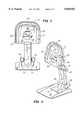
- FIG. 1is an elevation view of an illustrative embodiment of the patient support apparatus or stand of the present invention
- FIG. 2is a frontal view of the stand of FIG. 1 at an angle orthogonal to the patient bearing surface;
- FIGS. 3 and 4are, respectively, perspective views from the front and rear of the stand of FIG. 1;
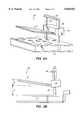
- FIGS. 5A and 5Bare, respectively, perspective and side views of a the tissue compression and imaging apparatus constructed in accordance with the principles of the present invention
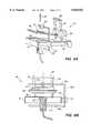
- FIGS. 6A and 6Bare, respectively, perspective and front sectional views of a first illustrative imaging and biopsy apparatus constructed in accordance with the present invention.
- FIGS. 7A and 7Bare, respectively, perspective and front sectional views of a second illustrative imaging and biopsy apparatus constructed in accordance with the present invention.
- FIGS. 8A and 8Bare, respectively, perspective and front sectional views of a third illustrative imaging and biopsy apparatus constructed in accordance with the present invention.
- the present inventionis described with respect to an illustrative system for performing imaging of biological tissue, and for conducting biopsy of such tissue, which at both the system level and component level represent significant advances over previously known technology for imaging and biopsy of tissue.
- the present inventionincludes novel features directed to (1) a patient support stand for use in imaging and/or biopsy of tissue, (2) apparatus and method for inducing traction in biological tissue to be imaged and/or biopsied, and (3) apparatus and methods for image-guided biopsy of tissue.
- Stand 10comprises base 11, vertical pillar 12, frame 13 supporting patient bearing surface 14 and imaging system support column 15.
- Nonslip mat 16may comprise a rubber sheet overlying a plywood, plastic or metal plate, and includes cutout 17 to fit snugly around base 11. Nonslip mat 16 ensures that chair 18, upon which patient P is seated, does not slide away from stand 10 when the patient inclines onto patient bearing surface 14 as shown in FIG. 1.
- Vertical pillar 12carries foot supports 19 which may be vertically adjustably positioned in holes 20 on vertical pillar 12 to accommodate the patient's height.
- Vertical pillar 12is preferably constructed of metal plate, e.g., steel, welded along the edges to form a hollow box-like configuration, so that electrical cable associated with the imaging system may pass through the interior of vertical pillar 12.
- Frame 13is preferably formed of thin-walled metal or metal alloy tubing and is connected to the upper lateral surfaces of vertical pillar 12 by suitable means, e.g., by bolts or welds.
- Frame 13includes substantially horizontal arms 21, vertical frame elements 22 and top connecting member 23 joining the upper ends of vertical frame elements 22.
- Horizontal arms 21, vertical frame elements 22 and top connecting member 23may be permanently fastened together by welding, or other suitable means.
- the tubing used to manufacture the components of frame 13may have stepped outer diameters so that the frame elements may be removably interlocked with one another, thereby permitting disassembly of the frame to enhance portability.
- Patient bearing surface 14is carried within frame 13 along its periphery to support the weight of the patient's torso when the patient is inclined against bearing surface 14, and includes opening 24 through which the patient extends a breast for imaging or biopsy, as described hereinbelow.
- Patient bearing surface 14may comprise a thin, rigid, plastic or metal alloy backing covered by a thin layer of medium density closed cell foam padding.
- the foam padding of patient bearing surface 14may in addition be covered with a cleanable, breathable fabric, that will not induce the patient to perspire at points of contact.
- patient bearing surface 14may be slightly concave.
- Patient bearing surface 14may also include head support 25, which may be either integrally formed from the padding covering patient bearing surface 14, or may consist of a detachable and removable pillow or cushion fastened to the patient bearing surface by suitable means, such as snaps or Velcro.
- head support 25may be either integrally formed from the padding covering patient bearing surface 14, or may consist of a detachable and removable pillow or cushion fastened to the patient bearing surface by suitable means, such as snaps or Velcro.
- Patient bearing surface 14is fastened to frame 13 around its periphery to tabs 26 (see FIG. 4) which are inwardly disposed from vertical frame elements 22 and top connecting member 23.
- Patient bearing surface 14may be fastened to tabs 26 by any suitable means, such as bolts, snaps, or screws, so that patient bearing surface 14 may be readily removed for transit or cleaning of stand 10.
- patient support member 14may comprise a sturdy fiber or breathable plastic mesh material stretched under tension across frame 13, thus further reducing the thickness of the patient bearing surface.
- Frame 13includes hand rail 27 disposed around its circumference, including along horizontal arms 21.
- Hand rail 26serves multiple functions in the embodiment of FIGS. 1-4. First, hand rail 26 provides a grip that the patient may use in properly orienting herself with respect to stand 10. Second, the hand rail extending along horizontal arms 21 provides a comfortable surface for the patient to lay her arms atop during the imaging and/or biopsy procedure. Finally, during the more physically and psychologically distressing moments of the biopsy examination, the patient may grip hand rails 26 to obtain a sense of control and security.
- frame 13 and hand rail 26are covered with a textured, medium density, self-skinning closed cell foam, e.g., urethane, so that the resulting structure is not unpleasant to the touch.
- Hand rails 26may be either permanently affixed to frame 13, or alternatively, may be connected to sections of frame 13 for disassembly when frame 13 is disassembled, as described hereinabove.
- Imaging system 30an illustrative embodiment of which is described hereinafter, is rotatably connected to imaging support column 15.
- Imaging system 30provides images of the interior features of the tissue extended through opening 24 using any of a number of technologies, including, for example, radiography, ultrasound and radar.
- imaging system 30may rotated about an axis located parallel to the plane of the compression surfaces of the imaging system, to enable the imaging system to be rotated with respect to the tissue extended through opening 24 of patient bearing surface 14.
- Frame 13is connected to vertical pillar 12 so that the patient becomes inclined in a range of about 5 to 25 degrees, and preferably about 20 degrees, from the vertical when the patient's torso contacts patient bearing surface 14.
- the patientremains seated while the breast to be examined is extended through opening 24. It is expected that both by gravity and the load created by the patient's body against patient bearing surface 14 will tend to thrust the breast through opening 24, thus enhancing the clinician's access relative to free-hand palpitation.
- the significance of allowing the patient to remain seatedrelates to applicants' findings that certain test subjects report feelings of greater security while oriented in a sitting posture, as opposed to greater feelings of insecurity and vulnerability when lying prone, as is typical for stereotactic biopsy tables.
- inclination of the patientenhances the clinician's access to the patient's tissue in the vicinity of the chest wall.
- patient Pwhen patient P is seated on chair 18, she can support the weight of her torso against patient bearing surface 14 while maintaining an inclined seated position.
- patient Pmay be aware of the presence of the clinician C seated on chair 28 behind stand 10, patient P cannot directly view the activities of the clinician, since her view of the breast extended through opening 24 is shielded by patient bearing surface 14 and frame 13.
- stand 10will beneficially enable the patient to remain aware of the clinician's presence, thus provide reassurance to the patient, while shielding the patient from a direct view of the tissue being examined.
- stand 10facilitates safe and quick removal of the patient from the stand 10 to a prone position for recovery.
- stand 10When used in conjunction with the ultrasound imaging systems described hereinbelow, stand 10 requires none of the shielding required for stereotactic tables, thereby reducing the size and cost of the apparatus relative to previously known devices. In particular, applicants expect that stand 10 in accordance with the present invention may be conveniently used by most smaller health practices with a minimum of dedicated office space.
- stand 10because the relatively simple construction of stand 10 enables the apparatus to be produced at lower cost than previously known systems, systems such as described hereinabove may be made more affordable to a larger segment of the health community, in turn increasing the availability of screening to a larger segment of the patient population.
- imaging apparatus 30constructed in accordance with the present invention is described.
- the compression surfaces of imaging apparatus 30are arranged so as to induce traction in the patient's tissue that draws the tissue away from the patient's chest during compression.
- the details of the imaging systemare first described, after which the features of the imaging system pertinent to the present invention are set forth.
- imaging system 30comprises an ultrasound transducer housed in enclosure 31.
- the internal arrangement of the ultrasound transducer within enclosure 31is as described with respect to FIGS. 6, 7 and 13 of commonly assigned U.S. Pat. No. 5,479,927, the entirety of which is incorporated herein by reference.
- Imaging system 30includes sonolucent lower compression plate 32 and upper compression plate 33 affixed to slide block 34.
- Slide block 34is adjustably supported on bars 35 so that top block 36 limits the travel of slide block 34 away from enclosure 31.
- the ultrasound transduceris coupled to a microprocessor that displays an image corresponding to the region scanned by the ultrasound transducer.
- enclosure 31contains an ultrasound transducer movably supported on a gantry arrangement so that the ultrasound transducer may be driven to sweep the area of lower compression surface 34, thereby generating a plurality of ultrasonic images orthogonal to the plane of the lower compression surface 32.
- the ultrasound transducermay comprise a single piston, annular or phased array imaging device of conventional design that preferably operates in a range of about 2 to 15 MHz. More preferably, the ultrasound transducer produces a signal in the transmit mode of a 10 MHz burst having a 100% bandwidth, and may be coupled to the underside of the lower compression plate using a suitable acoustic coupling.
- the gantry arrangement contained in enclosure 31supports a gantry for movement in distal and proximal directions (towards and away from the patient) driven by a motorized track or cable system.
- the gantryin turn comprises a carriage that supports the ultrasound transducer.
- the gantryincludes motorized drive means for moving the carriage laterally (side-to-side) with respect to the patient's chest wall.
- the motorized systemsmay comprise cable and pulley systems, toothed belts and gear arrangements, threaded blocks carried on a threaded drive rods controlled by encoders and stepper motors, or other suitable means.
- Lower compression plate 32is preferably formed of a sonolucent material, such as Surlyn® ionomers, such as Surlyn® 8940, available from E. I. Du Pont de Nemours and Company, Wilmington, Del., or a polymethyl pentene, such as TPX® MX-002 and MX-004, available from Mitsui & Co., Tokyo, Japan.
- Upper compression platemay likewise be formed of a sonolucent material, or may be of conventional construction.
- the above-described ultrasonic imaging systemis preferably employed with a gel pad (not shown), that serves to acoustically couple the lower compression surface 32 to the tissue, as described in the above-incorporated U.S. Pat. No. 5,479,927.
- Imaging system 30may alternatively include a conventional radiographic arrangement wherein the X-ray image is converted to a digitized image which is displayed for the clinician's observation.
- support bars 35 on which slide block 34 is disposedare canted forward by an angle ⁇ of up to about 15 degrees, and preferably about 4 degrees from a plane parallel to the plane of the patient's chest wall.
- upper compression plate 33is inclined at an angle ⁇ of up to about 45 degrees, and preferably 4 degrees, from a plane orthogonal to the plane of patient's chest wall.
- Lower compression surface 32is angled downward at an angle ⁇ of up to 90 degrees, and preferably 4 degrees, from that same plane.
- Applicanthas determined that by canting support bars 32 towards the patient by an angle ⁇ , inclining the upper compression plate by an angle ⁇ , and declining the lower compression plate by and angle ⁇ , a state of traction can be induced in the patient's tissue that draws the tissue away from the patient's chest wall, thereby enhancing the capability to image tissue near the patient's chest wall.
- the traction effect induced by the above described systemis accomplished as follows: First, the patient inserts the tissue to be examined between the upper compression plate 33 and lower compression surface 32. Next, upper compression plate 33 is lowered by moving slide block 34 down support bars 35 until upper compression plate 33 contacts the tissue. As slide block 34 and upper compression plate 33 are urged further towards lower compression surface 32, the tissue becomes flattened.
- upper compression plate 33Due to the cant of support bars 35, continued downward movement of upper compression plate 33 causes the upper compression plate to be displaced away from the patient's chest wall, thereby inducing a traction force in the tissue contacting the upper compression plate. This traction force tends to pull the tissue away from the chest wall, permitting enhanced imaging capability.
- Applicant's inventionrepresents a subtle but significant departure from previously known compression arrangements, wherein the compression plates typically move orthogonally during the tissue compression step.
- the tissueis generally forced outwardly, thus causing the tissue near the chest wall to be forced inwardly, i.e., into the patient's chest cavity.
- the method of canting and inclining the components of the imaging systemprovides improved imaging capability with respect to previously known systems.
- This biopsy apparatusprovides the capability to perform biopsy under the guidance of real-time ultrasonic images of the tissue.
- a preferred embodiment of the biopsy system for use with stand 10 and imaging system 30 of the present inventionis described in co-pending and commonly assigned U.S. patent application Ser. No. 08/421,381, which is incorporated herein by reference in its entirety.
- a biopsy deviceis guided to a target location within the patient's tissue using ultrasonic images displayed on a display screen monitored by the clinician.
- the imaging system therein describedemploys an ultrasonic scanner having the components described hereinabove with respect to FIG. 5.
- the biopsy devicewhich may be a biopsy needle, biopsy gun or similar device having a cannula to obtain a tissue core, is fastened to an electronic tracking arrangement that produces an indicator of the location of the tissue-effecting end of the biopsy device, i.e, needle or center of cannula, which is superimposed on a display of the ultrasound image of the tissue.
- the needle or cannula trajectorymay be determined prior to actual insertion of the device into the tissue, thereby reducing the need for repeatedly inserting and withdrawing the device to obtain samples of a suspected lesion.
- FIGS. 6 through 8alternative embodiments of a biopsy and imaging system are described to that disclosed in the above-incorporated application Ser. No. 08/421,381, and which provide ultrasonic scanning and image-guided biopsy using conventional ultrasound transducers.
- FIGS. 6A and 6Ba first embodiment of an image-guided biopsy system constructed in accordance with the present invention is described.
- Biopsy system 40includes rigid housing 41 including sonolucent lower compression plate 42 and guide arm 43. Support bars 44 are affixed to housing 41 and vertically adjustably support slide block 45 and upper compression plate 46. Upper compression plate 46 includes window 47 through which the needle or cannula of a biopsy device may be inserted, as described hereinafter. Top block 48 limits upward travel of slide block 45 on support bars 44. Support bars 44 are canted forward by an angle ⁇ , upper compression plate is inclined at an angle ⁇ , and lower compression plate 42 is declined at an angle ⁇ , as described hereinabove with respect to FIG. 5.
- Guide arm 43includes a C-shaped support arm 49 which is fastened to slide block 50.
- Slide block 50is disposed for proximal and distal movement along guide arm 43.
- C-shaped support arm 49includes lower arm 49a, vertical arm 49b and upper arm 49c.
- Lower arm 49acarries holder 51 which is configured to hold an ultrasound transducer 52 so that it is acoustically coupled to the underside of lower compression plate 42.
- Upper arm 49cincludes biopsy device support block 53 for removably carrying a biopsy device, such as needle 54, as described in the above-incorporated U.S. application Ser. No. 08/421,381.
- biopsy device support block 53 on C-shaped support arm 49holds biopsy device 54 so that the needle or center of the cannula of the device is aligned with ultrasound transducer 52.
- Ultrasound transducerwhich may be of conventional design, is connected to a suitable processor and display (not shown) for generating an ultrasound image that is orthogonal to the plane of lower compression plate 42.
- a suitable processor and displaynot shown
- biopsy device 54may be guided to a selected region of the tissue under guidance of the ultrasound image generated by ultrasound transducer 52.
- C-shaped support arm 49provides additional advantages for use in imaging and biopsying tissue, as will now be described.
- Holder 51, ultrasound transducer 52 and biopsy device support block 53are maintained in relative alignment along a plane substantially parallel to the patient's chest by C-shaped support arm 49.
- the clinicianis able to obtain and display images of the tissue to conduct a thorough examination.
- holder 51 and biopsy device support block 53may be moved laterally along lower arm 49a and upper arm 49c, respectively, while still maintaining proximal and distal alignment of the biopsy device with the ultrasound image, i.e., both elements remain in the same plane relative to the chest wall. Further, the trajectory of the biopsy device may be determined in the ultrasound image simply by contacting the needle or cannula to the tissue, thus allowing biopsy device support block 53 to be moved along upper arm 49c to position the biopsy device.
- FIGS. 6A and 6Bprovides much of the functionality described with respect to the previously described embodiment, but with lower cost components.
- biopsy system 40employs a conventional ultrasound transducer that is manually moved to scan the tissue, much of the drive circuitry and electronic tracking apparatus of the previously described embodiment may be omitted.
- Biopsy system 60 of FIGS. 7A and 7Bincludes rigid housing 61 including sonolucent lower compression plate 62, support bars 63, slide block 64, top block 65, and upper compression plate 66 arranged as described for biopsy system 40 of FIG. 6. Support bars 63, upper compression plate 66 and lower compression plate 62 are configured as described hereinabove with respect to FIG. 5.
- Guide arm 67comprises an L-shaped member having first leg 67a disposed parallel to the lateral surface of housing 61 and second leg 67b slidably disposed in slot 68 in housing 61.
- Connector block 69is slidably disposed on first leg 67a of guide arm 67 for movement towards and away from the patient's chest.
- Connector block 67carries transducer support arm 70 which in turn supports holder 71 in which ultrasound transducer 72 is disposed.
- Connector block 69also provides a bore through which L-shaped support rod 73 is adjustable carried.
- Biopsy device support block 74is disposed on an end of L-shaped support rod 73 for carrying a biopsy device, such as needle 75. As shown in FIG. 7B, biopsy device support block 74 holds the biopsy device so that the needle or cannula of the biopsy device is aligned with the image field of ultrasound transducer 72.
- Second leg 67bis supported within housing 61 by suitable elements so that second leg 67b may be moved in a plane parallel to the patient's chest to adjust the side to side positioning of ultrasound transducer 72 and biopsy device support block 71 while maintaining these components in alignment.
- L-shaped support rod 73may be vertically adjusted relative to the upper compression plate to vary the height of the biopsy device support block above the patient's tissue.
- the embodiment of FIG. 7maintains complete alignment of biopsy device support block 74 and ultrasound transducer 72, even during side-to-side movement of the scanner, by translating the entire arrangement in connection with movement of second leg 67b of guide arm 67.
- the embodiment of FIG. 7therefore not only provides the image-guided functionality of previously described embodiments, but retains complete alignment of the biopsy device and the ultrasound image.
- Biopsy system 80 of FIGS. 8A and 8Bincludes rigid housing 81 including sonolucent lower compression plate 82, support bars 83, slide block 84, top block 85, and upper compression plate 86 arranged as described for biopsy system 40 of FIG. 6.
- Support bars 83, upper compression plate 86 and lower compression plate 82are configured as described hereinabove with respect to FIG. 5.
- Guide arm 87is affixed to one or both sides of housing 81 (only one such guide is shown for clarity in FIG. 8A).
- Connector block 88carries transducer support arm 89 which in turn supports holder 90 in which ultrasound transducer 91 is disposed.
- Connector block 88also provides a bore through which support rod 92 is adjustably carried.
- Biopsy device support block 93is disposed on an end of support rod 92 for carrying a biopsy device, such as needle 94.
- transducer support arm 89aligns ultrasound transducer 91 with biopsy device support block 93 in a plane parallel to the patient's chest wall.
- support rod 92has disposed within it a printed circuit board arrangement of parallel, spaced-apart copper strips and connector block 88 includes a linear encoder that senses the static capacitance of the copper strips as the encoder is manually slid through connector block 88.
- the linear encoderoutputs a signal corresponding to its displacement from a preset reference point, preferably, the upper surface of lower compression plate 82.
- the signal output by linear encoderis provided to a computer (not shown) via connecting cable 95.
- the linear encoderpreferably has a displacement accuracy of about plus/minus 0.05 mm, and is available from Sylvac S. A., Crissier, Switzerland, and distributed in the United States by Fowler Company, Inc., Chicago, Ill., as Part No. 54-050-000.
- Biopsy system 80 of FIG. 7provides partial alignment of the biopsy device support block 93 with ultrasound transducer 91 through the connection of transducer support arm 89 to connector block 88.
- the clinicianis assured that the needle or cannula trajectory of the biopsy device will intercept the tissue displayed in the ultrasound image.
- the use of a linear encoder in conjunction with connector block 88enables the vertical height of biopsy device to be determined and the needle or cannula trajectory to be displayed superimposed on the ultrasound image of the tissue as described in the above-incorporated U.S. application Ser. No. 08/421,381.
Landscapes
- Health & Medical Sciences (AREA)
- Life Sciences & Earth Sciences (AREA)
- Surgery (AREA)
- Medical Informatics (AREA)
- Veterinary Medicine (AREA)
- Pathology (AREA)
- Nuclear Medicine, Radiotherapy & Molecular Imaging (AREA)
- Engineering & Computer Science (AREA)
- Biomedical Technology (AREA)
- Heart & Thoracic Surgery (AREA)
- Public Health (AREA)
- Molecular Biology (AREA)
- General Health & Medical Sciences (AREA)
- Animal Behavior & Ethology (AREA)
- Physics & Mathematics (AREA)
- Biophysics (AREA)
- Radiology & Medical Imaging (AREA)
- Acoustics & Sound (AREA)
- Neurosurgery (AREA)
- Oral & Maxillofacial Surgery (AREA)
- Ultra Sonic Daignosis Equipment (AREA)
- Apparatus For Radiation Diagnosis (AREA)
Abstract
Description
Claims (14)
Priority Applications (6)
| Application Number | Priority Date | Filing Date | Title |
|---|---|---|---|
| US08/680,559US5820552A (en) | 1996-07-12 | 1996-07-12 | Sonography and biopsy apparatus |
| DE69739573TDE69739573D1 (en) | 1996-07-12 | 1997-07-08 | |
| EP97936027AEP0926986B1 (en) | 1996-07-12 | 1997-07-08 | Sonography and biopsy apparatus |
| PCT/US1997/011437WO1998002095A1 (en) | 1996-07-12 | 1997-07-08 | Sonography and biopsy apparatus and methods of use |
| AU38795/97AAU3879597A (en) | 1996-07-12 | 1997-07-08 | Sonography and biopsy apparatus and methods of use |
| ES97936027TES2334525T3 (en) | 1996-07-12 | 1997-07-08 | ECOGRAPHY AND BIOPSY DEVICE. |
Applications Claiming Priority (1)
| Application Number | Priority Date | Filing Date | Title |
|---|---|---|---|
| US08/680,559US5820552A (en) | 1996-07-12 | 1996-07-12 | Sonography and biopsy apparatus |
Publications (1)
| Publication Number | Publication Date |
|---|---|
| US5820552Atrue US5820552A (en) | 1998-10-13 |
Family
ID=24731595
Family Applications (1)
| Application Number | Title | Priority Date | Filing Date |
|---|---|---|---|
| US08/680,559Expired - LifetimeUS5820552A (en) | 1996-07-12 | 1996-07-12 | Sonography and biopsy apparatus |
Country Status (6)
| Country | Link |
|---|---|
| US (1) | US5820552A (en) |
| EP (1) | EP0926986B1 (en) |
| AU (1) | AU3879597A (en) |
| DE (1) | DE69739573D1 (en) |
| ES (1) | ES2334525T3 (en) |
| WO (1) | WO1998002095A1 (en) |
Cited By (65)
| Publication number | Priority date | Publication date | Assignee | Title |
|---|---|---|---|---|
| US5978695A (en)* | 1997-08-18 | 1999-11-02 | Lucid Inc. | System for imaging mechanically stabilized tissue |
| US6110112A (en)* | 1998-03-06 | 2000-08-29 | Siemens Aktiengesellschaft | Medical guide apparatus for breath-coordinated puncturing of the body or a body cavity |
| US6122542A (en)* | 1998-11-25 | 2000-09-19 | Rubicor Medical, Inc. | Breast stabilization devices and imaging and interventional methods using the same |
| US6254538B1 (en)* | 1996-08-15 | 2001-07-03 | Life Imaging Systems, Inc. | System and process for performing percutaneous biopsy within the breast using three-dimensional ultrasonography |
| KR100310053B1 (en)* | 1999-04-21 | 2001-11-14 | 김선주 | Mammography |
| US6351660B1 (en) | 2000-04-18 | 2002-02-26 | Litton Systems, Inc. | Enhanced visualization of in-vivo breast biopsy location for medical documentation |
| US6419390B1 (en)* | 2001-03-26 | 2002-07-16 | Marianette Landis-Lowell | Folding mammography table and method of use |
| US6485426B2 (en)* | 2001-03-14 | 2002-11-26 | Sandhu Navparkash | Needle guide for ultrasound transducer |
| US20030007598A1 (en)* | 2000-11-24 | 2003-01-09 | U-Systems, Inc. | Breast cancer screening with adjunctive ultrasound mammography |
| US20030194051A1 (en)* | 2002-04-15 | 2003-10-16 | General Electric | Tomosynthesis X-ray mammogram system and method with automatic drive system |
| US20030194121A1 (en)* | 2002-04-15 | 2003-10-16 | General Electric Company | Computer aided detection (CAD) for 3D digital mammography |
| US20030194050A1 (en)* | 2002-04-15 | 2003-10-16 | General Electric Company | Multi modality X-ray and nuclear medicine mammography imaging system and method |
| US20030194115A1 (en)* | 2002-04-15 | 2003-10-16 | General Electric Company | Method and apparatus for providing mammographic image metrics to a clinician |
| US20030194048A1 (en)* | 2002-04-15 | 2003-10-16 | General Electric Company | Reprojection and backprojection methods and algorithms for implementation thereof |
| US20030215057A1 (en)* | 2002-05-15 | 2003-11-20 | General Electric Company | Scatter correction method for non-stationary X-ray acquisitions |
| US20040006347A1 (en)* | 2002-07-05 | 2004-01-08 | Sproul Michael E. | Ultrasonic cannula system |
| US6679850B1 (en) | 2002-08-30 | 2004-01-20 | Henry T. Uhrig | Breast stabilizer |
| US6682484B1 (en) | 2002-07-12 | 2004-01-27 | Koninklijke Philips Electronics N.V. | Compression plate for diagnostic breast imaging |
| US6707878B2 (en) | 2002-04-15 | 2004-03-16 | General Electric Company | Generalized filtered back-projection reconstruction in digital tomosynthesis |
| US20040068170A1 (en)* | 2000-11-24 | 2004-04-08 | U-Systems Inc.(Vii) | Breast cancer screening with ultrasound image overlays |
| US20040077972A1 (en)* | 2002-10-18 | 2004-04-22 | Mark Tsonton | Localization mechanism for an MRI compatible biopsy device |
| US6780179B2 (en) | 2002-05-22 | 2004-08-24 | Rubicor Medical, Inc. | Methods and systems for in situ tissue marking and orientation stabilization |
| US6805669B2 (en) | 2001-01-25 | 2004-10-19 | Rebecca L. Swanbom | Method and device for marking skin during an ultrasound examination |
| US20050079666A1 (en)* | 2002-04-05 | 2005-04-14 | French Roger Harquail | Method for providing nano-structures of uniform length |
| US20050089205A1 (en)* | 2003-10-23 | 2005-04-28 | Ajay Kapur | Systems and methods for viewing an abnormality in different kinds of images |
| US20060084868A1 (en)* | 2003-01-17 | 2006-04-20 | Hee-Boong Park | Apparatus for ultrasonic examination of deformable object |
| US20060115041A1 (en)* | 2004-11-26 | 2006-06-01 | Aurelie Roncaglioni | Equipment for mammography |
| US20060159318A1 (en)* | 2003-11-26 | 2006-07-20 | Alyassin Abdalmajeid M | Method, system and computer program product for multi-modality registration using virtual cursors |
| US20060210021A1 (en)* | 2005-03-16 | 2006-09-21 | Kazuhiro Matsumoto | Radiographic imaging apparatus |
| US20060262898A1 (en)* | 2005-05-20 | 2006-11-23 | Varian Medical Systems, Inc. | System and method for imaging and treatment of tumorous tissue in breasts using computed tomography and radiotherapy |
| WO2006030406A3 (en)* | 2004-09-15 | 2007-05-24 | Scient Biopsy Ltd | Breast cancer detection and biopsy |
| US7223238B2 (en) | 2001-01-25 | 2007-05-29 | Swanbom Rebecca L | Method and device for marking skin during an ultrasound examination |
| US20070225605A1 (en)* | 2001-01-25 | 2007-09-27 | Swanbom Rebecca L | Method and Device for Marking Skin During an Ultrasound Examination |
| US20070282221A1 (en)* | 2006-06-02 | 2007-12-06 | U-Systems, Inc. | Ultrasound assisted and x-ray assisted biopsy devices |
| US20080004526A1 (en)* | 2004-09-15 | 2008-01-03 | Scientific Biopsy Ltd. | Breast Cancer Detection and Biopsy |
| WO2008020439A2 (en) | 2006-08-17 | 2008-02-21 | Sialo Technology Israel Ltd | All-in-one optical microscopic handle |
| US20080080668A1 (en)* | 2006-09-29 | 2008-04-03 | Fujifilm Corporation | Mammographic apparatus, breast compression plate, and breast fixing method |
| WO2008043673A1 (en)* | 2006-10-13 | 2008-04-17 | Siemens Aktiengesellschaft | Mammography unit comprising a pressure plate and an object stage |
| US20090086928A1 (en)* | 2007-09-28 | 2009-04-02 | Fujifilm Corporation | X-ray imaging apparatus |
| US7517348B2 (en) | 1998-09-03 | 2009-04-14 | Rubicor Medical, Inc. | Devices and methods for performing procedures on a breast |
| US20090175409A1 (en)* | 2006-05-08 | 2009-07-09 | Sirona Dental Systems Gmbh | Dental x-ray apparatus comprising a patient-positioning system arranged on a support and provided with a forehead rest |
| JP2009525093A (en)* | 2006-02-03 | 2009-07-09 | シーメンス アクチエンゲゼルシヤフト | Positioning device for mammography equipment |
| US7597663B2 (en) | 2000-11-24 | 2009-10-06 | U-Systems, Inc. | Adjunctive ultrasound processing and display for breast cancer screening |
| US7615008B2 (en) | 2000-11-24 | 2009-11-10 | U-Systems, Inc. | Processing and displaying breast ultrasound information |
| EP2009465A4 (en)* | 2006-03-31 | 2010-03-03 | Shimadzu Corp | Mammography system |
| USD628295S1 (en)* | 2009-11-24 | 2010-11-30 | Shimadzu Corporation | Positron emission tomography camera for breast imaging |
| FR2951073A1 (en)* | 2009-10-14 | 2011-04-15 | Bernard Gotti | Device i.e. medical examination armchair, for realizing e.g. mammography medical gestures of patient, has leg supporting seat and mounted on spring that adjusts position of patient, where seat has backrest equipped with bucket seat |
| US7940966B2 (en) | 2000-11-24 | 2011-05-10 | U-Systems, Inc. | Full-field breast image data processing and archiving |
| DE102010009011A1 (en)* | 2010-02-24 | 2011-08-25 | Siemens Aktiengesellschaft, 80333 | compression unit |
| US8323675B2 (en) | 2004-04-20 | 2012-12-04 | Genzyme Corporation | Soft tissue prosthesis for repairing a defect of an abdominal wall or a pelvic cavity wall |
| US8464378B2 (en) | 2010-07-27 | 2013-06-18 | Institute Of Nuclear Energy Research Atomic Energy Council | Medical inspection apparatus |
| US20130259193A1 (en)* | 2012-04-03 | 2013-10-03 | Nathan J. Packard | Apparatus and method for breast imaging |
| US20160242709A1 (en)* | 2015-02-24 | 2016-08-25 | Siemens Aktiengesellschaft | Breast examination apparatus and compression plate for a breast examination apparatus |
| USD788310S1 (en)* | 2015-06-25 | 2017-05-30 | Canon Kabushiki Kaisha | Mammography apparatus for medical treatment |
| USD788309S1 (en)* | 2015-06-25 | 2017-05-30 | Canon Kabushiki Kaisha | Mammography apparatus for medical treatment |
| US9950194B2 (en) | 2014-09-09 | 2018-04-24 | Mevion Medical Systems, Inc. | Patient positioning system |
| US20180116612A1 (en)* | 2015-05-13 | 2018-05-03 | Fujidenolo Co., Ltd. | Fixture fitting device |
| USD857203S1 (en)* | 2017-11-15 | 2019-08-20 | Samsung Electronics Co., Ltd. | Magnetic resonance imaging device |
| US20200121268A1 (en)* | 2017-06-27 | 2020-04-23 | Sigmascreening B.V. | Seat adapted for use with a mammography apparatus |
| US20200138391A1 (en)* | 2005-05-03 | 2020-05-07 | The Regents Of The University Of California | Biopsy systems for breast computed tomography |
| CN111655155A (en)* | 2017-12-20 | 2020-09-11 | 皇家飞利浦有限公司 | Ultrasound apparatus for in situ ultrasound imaging |
| US20230024001A1 (en)* | 2019-12-23 | 2023-01-26 | Koninklijke Philips N.V. | Magnetic Resonance Breast Support |
| US20230143589A1 (en)* | 2021-11-08 | 2023-05-11 | Ims Giotto S.P.A. | Medical analysis apparatus |
| JP2023070607A (en)* | 2021-11-09 | 2023-05-19 | 学校法人早稲田大学 | ultrasonic inspection robot |
| US12201462B2 (en) | 2019-12-17 | 2025-01-21 | Medtec Llc | Patient imaging and treatment table extension with integrated handrails |
Families Citing this family (3)
| Publication number | Priority date | Publication date | Assignee | Title |
|---|---|---|---|---|
| KR101112659B1 (en)* | 2009-04-14 | 2012-02-16 | 삼성메디슨 주식회사 | Biopsy apparatus and ultrasonic diagnostic apparatus therewith |
| KR101010597B1 (en)* | 2009-04-14 | 2011-01-24 | 주식회사 메디슨 | Biopsy device detachable ultrasonic diagnostic device |
| JP5721477B2 (en) | 2010-04-22 | 2015-05-20 | キヤノン株式会社 | measuring device |
Citations (131)
| Publication number | Priority date | Publication date | Assignee | Title |
|---|---|---|---|---|
| US2707662A (en)* | 1949-05-27 | 1955-05-03 | Picker X Ray Corp Waite Mfg | Tiltably X-ray table with extension panel |
| US3165630A (en)* | 1961-06-13 | 1965-01-12 | Polaroid Corp | Table for holding and positioning a female subject and film during breast x-ray exposures |
| US3420097A (en)* | 1963-03-14 | 1969-01-07 | Babcock & Wilcox Ltd | Vibration coupling device for an ultrasonic transducer |
| US3480002A (en)* | 1967-01-24 | 1969-11-25 | Magnaflux Corp | Medical ultrasonic scanning system |
| US3556081A (en)* | 1968-05-20 | 1971-01-19 | Holotron Corp | Breast holder for mammograph |
| US3589361A (en)* | 1968-06-10 | 1971-06-29 | Abbott Lab | Intravenous catheter unit with flexible wing support and inserter means |
| US3609355A (en)* | 1968-05-31 | 1971-09-28 | Schick X Ray Co Inc | X-ray mammograph in which the x-ray source and film cassette are rotatable about the subject being photograph |
| US3765403A (en)* | 1968-05-20 | 1973-10-16 | Holotron Corp | Ultrasonic imaging techniques and mammograph equipment |
| DE2335576A1 (en) | 1973-07-13 | 1975-01-30 | Philips Patentverwaltung | X-ray mammographic diagnostic appts. - has compensating liquid cushion attached to compression unit |
| US3921442A (en)* | 1973-11-28 | 1975-11-25 | Automation Ind Inc | Acoustic couplant for use with an ultrasonic search unit |
| US3939696A (en)* | 1972-06-08 | 1976-02-24 | The Commonwealth Of Australia | Scanning ultrasonic inspection method and apparatus |
| US3963933A (en)* | 1975-08-18 | 1976-06-15 | General Electric Company | Mammography fixture |
| US3971950A (en)* | 1975-04-14 | 1976-07-27 | Xerox Corporation | Independent compression and positioning device for use in mammography |
| US3973126A (en)* | 1975-07-31 | 1976-08-03 | General Electric Company | Mammography |
| US3991316A (en)* | 1972-03-24 | 1976-11-09 | Siemens Aktiengesellschaft | Apparatus for X-ray examination |
| US3990300A (en)* | 1974-02-21 | 1976-11-09 | The Commonwealth Of Australia | Moving ultrasonic transducer array |
| US4021771A (en)* | 1975-07-07 | 1977-05-03 | Holosonics, Inc. | Scan acoustical holographic imaging apparatus |
| US4051380A (en)* | 1976-03-31 | 1977-09-27 | Lasky Harold J | Apparatus and method for supporting and positioning the body to facilitate radiographic mammography procedures |
| US4058114A (en)* | 1974-09-11 | 1977-11-15 | Siemens Aktiengesellschaft | Ultrasonic arrangement for puncturing internal body organs, vessels and the like |
| US4094306A (en)* | 1975-05-01 | 1978-06-13 | The Commonwealth Of Australia, C/O The Department Of Health | Apparatus for ultrasonic examination |
| US4099880A (en)* | 1976-08-11 | 1978-07-11 | Tsutomu Kano | Method and an apparatus for stereoscopic measurement utilizing a three-dimensional image |
| US4167180A (en)* | 1975-05-01 | 1979-09-11 | The Commonwealth Of Australia, Care Of The Department Of Health | Method and apparatus for ultrasonic examination |
| US4206763A (en)* | 1978-08-01 | 1980-06-10 | Drexel University | Ultrasonic scanner for breast cancer examination |
| USRE30397E (en)* | 1976-04-27 | 1980-09-09 | Three-dimensional ultrasonic imaging of animal soft tissue | |
| US4249541A (en)* | 1979-04-26 | 1981-02-10 | David S. Pratt | Biopsy device |
| US4285010A (en)* | 1973-10-29 | 1981-08-18 | Advanced Diagnostic Research Corporation | Ultrasonic interrogating system and exciter-detector circuit therefor |
| SU896539A2 (en) | 1980-04-14 | 1982-01-07 | Каунасский Политехнический Институт Им.Антанаса Снечкуса | Ultrasonic transducer for biological investigations |
| US4343799A (en)* | 1981-03-20 | 1982-08-10 | The Upjohn Company | Use of derivatives of 6α-methylprednisolone for the prevention or reduction of adriamycin-induced cardiotoxicity |
| US4347850A (en)* | 1980-03-19 | 1982-09-07 | Indianapolis Center For Advanced Research, Inc. | Direct water coupling device for ultrasound breast scanning in a supine position |
| GB2094590A (en) | 1981-02-12 | 1982-09-15 | Univ New York | Apparatus for stereotactic surgery |
| US4363326A (en)* | 1980-12-22 | 1982-12-14 | Advanced Diagnostic Research Corporation | Ultrasonic apparatus for needle insertion |
| US4369284A (en)* | 1977-03-17 | 1983-01-18 | Applied Elastomerics, Incorporated | Thermoplastic elastomer gelatinous compositions |
| DE3226976A1 (en) | 1981-07-20 | 1983-02-03 | Siemens AG, 1000 Berlin und 8000 München | ULTRASONIC APPARATUS FOR MEDICAL EXAMINATIONS |
| US4402324A (en)* | 1981-06-29 | 1983-09-06 | Technicare Corporation | Biopsy needle guide for sector scanner |
| DE3227624A1 (en) | 1982-07-23 | 1984-01-26 | Siemens AG, 1000 Berlin und 8000 München | Device for examining the female breast using ultrasound |
| US4434799A (en)* | 1982-03-02 | 1984-03-06 | Siemens Ag | Ultrasound apparatus for medical examinations |
| US4455872A (en)* | 1978-03-03 | 1984-06-26 | Commonwealth Of Australia, The Department Of Health | Rotating ultrasonic scanner |
| US4465069A (en)* | 1981-06-04 | 1984-08-14 | Barbier Jean Y | Cranial insertion of surgical needle utilizing computer-assisted tomography |
| US4469106A (en)* | 1982-09-02 | 1984-09-04 | Advanced Technology Laboratories, Inc. | Needle guide for use with medical ultrasonic scanning apparatus |
| US4485819A (en)* | 1980-01-21 | 1984-12-04 | Wolfgang Igl | Mechanical accessory for commercially available compound apparatuses for echo mammography |
| US4497325A (en)* | 1982-07-15 | 1985-02-05 | Wedel Victor J | Ultrasound needle, biopsy instrument or catheter guide |
| US4501278A (en)* | 1981-02-09 | 1985-02-26 | Yokogawa Hokushin Electric Corporation | Ultrasonic probe for puncture treatment |
| US4527569A (en)* | 1982-11-26 | 1985-07-09 | South African Inventions Develop. Corp. | Device for guiding a surgical needle into a blood vessel |
| US4541436A (en)* | 1982-08-19 | 1985-09-17 | Siemens Aktiengesellschaft | Ultrasonic tomography device |
| US4545385A (en)* | 1982-03-23 | 1985-10-08 | Siemens Aktiengesellschaft | Ultrasound examination device for scanning body parts |
| US4573180A (en)* | 1983-11-08 | 1986-02-25 | Siemens Aktiengesellschaft | X-Ray diagnostic apparatus with a compression carriage |
| US4579123A (en)* | 1983-12-16 | 1986-04-01 | Hewlett-Packard Company | Stand-off device |
| US4583538A (en)* | 1984-05-04 | 1986-04-22 | Onik Gary M | Method and apparatus for stereotaxic placement of probes in the body utilizing CT scanner localization |
| US4592352A (en)* | 1984-11-30 | 1986-06-03 | Patil Arun A | Computer-assisted tomography stereotactic system |
| DE3447444A1 (en) | 1984-12-27 | 1986-07-03 | Hans, Wolfgang, 6700 Ludwigshafen | Ultrasound reservoir |
| US4599738A (en)* | 1984-04-17 | 1986-07-08 | Patrick Panetta | Universal mammography compression system |
| US4608989A (en)* | 1983-02-07 | 1986-09-02 | Medical Innovation Company A/S | Stand-off cell for an ultrasonic scanner head |
| US4613982A (en)* | 1983-05-30 | 1986-09-23 | Siemens Aktiengesellschaft | Radiodiagnostic apparatus for mammograms |
| US4613122A (en)* | 1983-08-19 | 1986-09-23 | Kabushiki Kaisha Toshiba | CT couch apparatus having a lift |
| US4618213A (en)* | 1977-03-17 | 1986-10-21 | Applied Elastomerics, Incorporated | Gelatinous elastomeric optical lens, light pipe, comprising a specific block copolymer and an oil plasticizer |
| US4618973A (en)* | 1985-11-01 | 1986-10-21 | Lasky Harold J | Mammographic X-ray apparatus |
| US4625555A (en)* | 1984-02-07 | 1986-12-02 | Terumo Kabushiki Kaisha | Ultrasonic measurement method, and apparatus therefor |
| US4671292A (en)* | 1985-04-30 | 1987-06-09 | Dymax Corporation | Concentric biopsy probe |
| US4681103A (en)* | 1985-03-11 | 1987-07-21 | Diasonics, Inc. | Ultrasound guided surgical instrument guide and method |
| US4686997A (en)* | 1985-07-03 | 1987-08-18 | The United States Of America As Represented By The Secretary Of The Air Force | Skeletal bone remodeling studies using guided trephine sample |
| US4722346A (en)* | 1983-12-16 | 1988-02-02 | Hewlett-Packard Company | Stand-off device with special fluid |
| US4727565A (en)* | 1983-11-14 | 1988-02-23 | Ericson Bjoern E | Method of localization |
| US4733661A (en)* | 1987-04-27 | 1988-03-29 | Palestrant Aubrey M | Guidance device for C.T. guided drainage and biopsy procedures |
| US4735215A (en)* | 1987-01-05 | 1988-04-05 | Goto David S | Soft tissue biopsy instrument |
| US4750487A (en)* | 1986-11-24 | 1988-06-14 | Zanetti Paul H | Stereotactic frame |
| US4774961A (en)* | 1985-11-07 | 1988-10-04 | M/A Com, Inc. | Multiple antennae breast screening system |
| US4784134A (en)* | 1986-11-17 | 1988-11-15 | Thomas Arana | Biopsy locator plate |
| US4791934A (en)* | 1986-08-07 | 1988-12-20 | Picker International, Inc. | Computer tomography assisted stereotactic surgery system and method |
| DE3405537C2 (en) | 1984-02-16 | 1989-03-16 | Lothar W. Dr.Med. 2000 Hamburg De Popp | |
| US4821727A (en)* | 1986-10-30 | 1989-04-18 | Elscint Ltd. | Mammographic biopsy needle holder system |
| US4844080A (en)* | 1987-02-19 | 1989-07-04 | Michael Frass | Ultrasound contact medium dispenser |
| US4862893A (en)* | 1987-12-08 | 1989-09-05 | Intra-Sonix, Inc. | Ultrasonic transducer |
| US4869247A (en)* | 1988-03-11 | 1989-09-26 | The University Of Virginia Alumni Patents Foundation | Video tumor fighting system |
| US4875478A (en)* | 1987-04-10 | 1989-10-24 | Chen Harry H | Portable compression grid & needle holder |
| US4890311A (en)* | 1987-06-30 | 1989-12-26 | Siemens Aktiengesellschaft | Biopsy means for an x-ray examination apparatus |
| US4898178A (en)* | 1987-04-24 | 1990-02-06 | Wedel Victor J | Monolithic disposable needle guide for ultrasound transducers |
| US4899756A (en)* | 1988-07-18 | 1990-02-13 | Sonek Jiri D | Articulated needle guide for ultrasound imaging and method of using same |
| US4911173A (en)* | 1987-11-13 | 1990-03-27 | Diasonics, Inc. | Biopsy attachment for ultrasound probe |
| US4930143A (en)* | 1986-09-19 | 1990-05-29 | Bengt Lundgren | Method and device for mammographic stereotactic punction of pathological lesions in the female breast |
| US4940061A (en)* | 1989-11-27 | 1990-07-10 | Ingress Technologies, Inc. | Biopsy instrument |
| US4944308A (en)* | 1987-11-19 | 1990-07-31 | C. R. Bard, Inc. | Tissue sampling device |
| US4962515A (en)* | 1989-11-13 | 1990-10-09 | The General Hospital Corporation | Ridged compression assembly for mammography apparatus |
| US4962752A (en)* | 1986-02-19 | 1990-10-16 | Siemens Aktiengesellschaft | Coupling member for a shock wave therapy device |
| US4966152A (en)* | 1987-07-21 | 1990-10-30 | Hewlett-Packard Company | Transducer |
| US4981142A (en)* | 1988-06-24 | 1991-01-01 | Dachman Abraham H | Compression device |
| US5003979A (en)* | 1989-02-21 | 1991-04-02 | University Of Virginia | System and method for the noninvasive identification and display of breast lesions and the like |
| US5007428A (en)* | 1987-04-21 | 1991-04-16 | The University Court Of The University Of Aberdeen | Apparatus for examining a body of living tissues |
| US5029193A (en)* | 1989-07-03 | 1991-07-02 | Siemens Aktiengesellschaft | X-ray diagnostic installation for mammography exposures |
| US5056523A (en)* | 1989-11-22 | 1991-10-15 | Board Of Regents, The University Of Texas System | Precision breast lesion localizer |
| US5078149A (en)* | 1989-09-29 | 1992-01-07 | Terumo Kabushiki Kaisha | Ultrasonic coupler and method for production thereof |
| US5078142A (en)* | 1989-11-21 | 1992-01-07 | Fischer Imaging Corporation | Precision mammographic needle biopsy system |
| US5083305A (en)* | 1989-04-28 | 1992-01-21 | General Electric Cgr S.A. | Radiation control device with variable active surface of the type sensitive to ionizing radiation |
| US5095910A (en)* | 1990-04-18 | 1992-03-17 | Advanced Technology Laboratories, Inc. | Ultrasonic imaging of biopsy needle |
| US5099503A (en)* | 1989-11-23 | 1992-03-24 | Planmed Oy | Method and device for controlling the operation of a mammographic X-ray apparatus |
| US5107843A (en)* | 1990-04-06 | 1992-04-28 | Orion-Yhtyma Oy | Method and apparatus for thin needle biopsy in connection with mammography |
| US5113420A (en)* | 1990-12-24 | 1992-05-12 | Texaco Inc. | Method and apparatus for positioning a sample with repeatable accuracy |
| DE4037387A1 (en) | 1990-11-22 | 1992-05-27 | Kari Dr Richter | Object imaging display for ultrasonic sonic scanning computer tomograph - superimposes echoes of primary radiation into summation image |
| DE3322053C2 (en) | 1983-06-18 | 1992-06-17 | Telefunken Systemtechnik Gmbh, 7900 Ulm, De | |
| US5158088A (en)* | 1990-11-14 | 1992-10-27 | Advanced Technology Laboratories, Inc. | Ultrasonic diagnostic systems for imaging medical instruments within the body |
| US5199056A (en)* | 1989-11-28 | 1993-03-30 | Darrah Carol J | Mammography compression paddle |
| US5205297A (en)* | 1988-03-25 | 1993-04-27 | Lectec Corporation | Multipurpose medical stimulation electrode |
| US5219351A (en)* | 1990-10-24 | 1993-06-15 | General Electric Cgr S.A. | Mammograph provided with an improved needle carrier |
| US5260871A (en)* | 1991-07-31 | 1993-11-09 | Mayo Foundation For Medical Education And Research | Method and apparatus for diagnosis of breast tumors |
| US5262468A (en)* | 1977-03-17 | 1993-11-16 | Applied Elastomerics, Inc. | Thermoplastic elastomer gelatinous compositions |
| US5273435A (en)* | 1992-07-16 | 1993-12-28 | The Mcw Research Foundation, Inc. | Tumor localization phantom |
| US5280427A (en)* | 1989-11-27 | 1994-01-18 | Bard International, Inc. | Puncture guide for computer tomography |
| US5305365A (en)* | 1992-11-24 | 1994-04-19 | Bennett X-Ray Technologies | Mammography system with rearwardly tilting mammograph |
| US5318028A (en) | 1993-06-07 | 1994-06-07 | Westinghouse Electric Corporation | High resolution ultrasound mammography system and boundary array scanner therefor |
| US5361768A (en) | 1992-06-30 | 1994-11-08 | Cardiovascular Imaging Systems, Inc. | Automated longitudinal position translator for ultrasonic imaging probes, and methods of using same |
| US5379769A (en) | 1992-11-30 | 1995-01-10 | Hitachi Medical Corporation | Ultrasonic diagnostic apparatus for displaying an image in a three-dimensional image and in a real time image and a display method thereof |
| US5386447A (en) | 1992-09-23 | 1995-01-31 | Fischer Imaging Corporation | Mammographic screening and biopsy apparatus |
| US5396897A (en) | 1992-01-16 | 1995-03-14 | The General Hospital Corporation | Method for locating tumors prior to needle biopsy |
| US5411026A (en) | 1993-10-08 | 1995-05-02 | Nomos Corporation | Method and apparatus for lesion position verification |
| US5415169A (en) | 1989-11-21 | 1995-05-16 | Fischer Imaging Corporation | Motorized mammographic biopsy apparatus |
| US5426685A (en) | 1991-11-27 | 1995-06-20 | Thermotrex Corporation | Stereotactic mammography system imaging |
| US5433202A (en) | 1993-06-07 | 1995-07-18 | Westinghouse Electric Corporation | High resolution and high contrast ultrasound mammography system with heart monitor and boundary array scanner providing electronic scanning |
| US5447154A (en) | 1992-07-31 | 1995-09-05 | Universite Joseph Fourier | Method for determining the position of an organ |
| US5450851A (en) | 1994-05-25 | 1995-09-19 | Advanced Technology Laboratories, Inc. | Ultrasonic probe assembly |
| US5474072A (en) | 1993-10-29 | 1995-12-12 | Neovision Corporation | Methods and apparatus for performing sonomammography |
| US5487387A (en) | 1994-06-03 | 1996-01-30 | Duke University | Method and apparatus for distinguishing between solid masses and fluid-filled cysts |
| US5488952A (en) | 1982-02-24 | 1996-02-06 | Schoolman Scientific Corp. | Stereoscopically display three dimensional ultrasound imaging |
| US5499989A (en) | 1994-12-22 | 1996-03-19 | Labash; Stephen S. | Breast biopsy apparatus and method of use |
| US5506877A (en) | 1994-11-23 | 1996-04-09 | The General Hospital Corporation | Mammography breast compression device and method |
| US5522787A (en) | 1994-01-25 | 1996-06-04 | Gregory Charles Robinson | Male sexual aid |
| US5524636A (en) | 1992-12-21 | 1996-06-11 | Artann Corporation Dba Artann Laboratories | Method and apparatus for elasticity imaging |
| US5594769A (en) | 1991-11-27 | 1997-01-14 | Thermotrex Corporation | Method and apparatus for obtaining stereotactic mammographic guided needle breast biopsies |
| US5595177A (en) | 1994-06-03 | 1997-01-21 | Harbor-Ucla Research And Education Institute, Inc. | Scintigraphy guided stereotaxic localizations apparatus for breast carcinomas |
| US5603326A (en) | 1993-03-22 | 1997-02-18 | Siemens Aktiengesellschaft | Method and apparatus for displaying an image obtained by echo signals |
| US5640956A (en) | 1995-06-07 | 1997-06-24 | Neovision Corporation | Methods and apparatus for correlating ultrasonic image data and radiographic image data |
| US5660185A (en) | 1995-04-13 | 1997-08-26 | Neovision Corporation | Image-guided biopsy apparatus with enhanced imaging and methods |
| US5664573A (en) | 1993-10-29 | 1997-09-09 | Neovision Corporation | Method and apparatus for performing sonomammography and enhanced X-ray imaging |
- 1996
- 1996-07-12USUS08/680,559patent/US5820552A/ennot_activeExpired - Lifetime
- 1997
- 1997-07-08WOPCT/US1997/011437patent/WO1998002095A1/enactiveApplication Filing
- 1997-07-08EPEP97936027Apatent/EP0926986B1/ennot_activeExpired - Lifetime
- 1997-07-08AUAU38795/97Apatent/AU3879597A/ennot_activeAbandoned
- 1997-07-08ESES97936027Tpatent/ES2334525T3/ennot_activeExpired - Lifetime
- 1997-07-08DEDE69739573Tpatent/DE69739573D1/denot_activeExpired - Lifetime
Patent Citations (136)
| Publication number | Priority date | Publication date | Assignee | Title |
|---|---|---|---|---|
| US2707662A (en)* | 1949-05-27 | 1955-05-03 | Picker X Ray Corp Waite Mfg | Tiltably X-ray table with extension panel |
| US3165630A (en)* | 1961-06-13 | 1965-01-12 | Polaroid Corp | Table for holding and positioning a female subject and film during breast x-ray exposures |
| US3420097A (en)* | 1963-03-14 | 1969-01-07 | Babcock & Wilcox Ltd | Vibration coupling device for an ultrasonic transducer |
| US3480002A (en)* | 1967-01-24 | 1969-11-25 | Magnaflux Corp | Medical ultrasonic scanning system |
| US3765403A (en)* | 1968-05-20 | 1973-10-16 | Holotron Corp | Ultrasonic imaging techniques and mammograph equipment |
| US3556081A (en)* | 1968-05-20 | 1971-01-19 | Holotron Corp | Breast holder for mammograph |
| US3609355A (en)* | 1968-05-31 | 1971-09-28 | Schick X Ray Co Inc | X-ray mammograph in which the x-ray source and film cassette are rotatable about the subject being photograph |
| US3589361A (en)* | 1968-06-10 | 1971-06-29 | Abbott Lab | Intravenous catheter unit with flexible wing support and inserter means |
| US3991316A (en)* | 1972-03-24 | 1976-11-09 | Siemens Aktiengesellschaft | Apparatus for X-ray examination |
| US3939696A (en)* | 1972-06-08 | 1976-02-24 | The Commonwealth Of Australia | Scanning ultrasonic inspection method and apparatus |
| DE2335576A1 (en) | 1973-07-13 | 1975-01-30 | Philips Patentverwaltung | X-ray mammographic diagnostic appts. - has compensating liquid cushion attached to compression unit |
| US4285010A (en)* | 1973-10-29 | 1981-08-18 | Advanced Diagnostic Research Corporation | Ultrasonic interrogating system and exciter-detector circuit therefor |
| US3921442A (en)* | 1973-11-28 | 1975-11-25 | Automation Ind Inc | Acoustic couplant for use with an ultrasonic search unit |
| US3990300A (en)* | 1974-02-21 | 1976-11-09 | The Commonwealth Of Australia | Moving ultrasonic transducer array |
| US4058114A (en)* | 1974-09-11 | 1977-11-15 | Siemens Aktiengesellschaft | Ultrasonic arrangement for puncturing internal body organs, vessels and the like |
| US3971950A (en)* | 1975-04-14 | 1976-07-27 | Xerox Corporation | Independent compression and positioning device for use in mammography |
| US4094306A (en)* | 1975-05-01 | 1978-06-13 | The Commonwealth Of Australia, C/O The Department Of Health | Apparatus for ultrasonic examination |
| US4167180A (en)* | 1975-05-01 | 1979-09-11 | The Commonwealth Of Australia, Care Of The Department Of Health | Method and apparatus for ultrasonic examination |
| US4021771A (en)* | 1975-07-07 | 1977-05-03 | Holosonics, Inc. | Scan acoustical holographic imaging apparatus |
| US3973126A (en)* | 1975-07-31 | 1976-08-03 | General Electric Company | Mammography |
| US3963933A (en)* | 1975-08-18 | 1976-06-15 | General Electric Company | Mammography fixture |
| US4051380A (en)* | 1976-03-31 | 1977-09-27 | Lasky Harold J | Apparatus and method for supporting and positioning the body to facilitate radiographic mammography procedures |
| USRE30397E (en)* | 1976-04-27 | 1980-09-09 | Three-dimensional ultrasonic imaging of animal soft tissue | |
| US4099880A (en)* | 1976-08-11 | 1978-07-11 | Tsutomu Kano | Method and an apparatus for stereoscopic measurement utilizing a three-dimensional image |
| US4369284A (en)* | 1977-03-17 | 1983-01-18 | Applied Elastomerics, Incorporated | Thermoplastic elastomer gelatinous compositions |
| US5262468A (en)* | 1977-03-17 | 1993-11-16 | Applied Elastomerics, Inc. | Thermoplastic elastomer gelatinous compositions |
| US4618213A (en)* | 1977-03-17 | 1986-10-21 | Applied Elastomerics, Incorporated | Gelatinous elastomeric optical lens, light pipe, comprising a specific block copolymer and an oil plasticizer |
| US4455872A (en)* | 1978-03-03 | 1984-06-26 | Commonwealth Of Australia, The Department Of Health | Rotating ultrasonic scanner |
| US4206763A (en)* | 1978-08-01 | 1980-06-10 | Drexel University | Ultrasonic scanner for breast cancer examination |
| US4249541A (en)* | 1979-04-26 | 1981-02-10 | David S. Pratt | Biopsy device |
| US4485819A (en)* | 1980-01-21 | 1984-12-04 | Wolfgang Igl | Mechanical accessory for commercially available compound apparatuses for echo mammography |
| US4347850A (en)* | 1980-03-19 | 1982-09-07 | Indianapolis Center For Advanced Research, Inc. | Direct water coupling device for ultrasound breast scanning in a supine position |
| SU896539A2 (en) | 1980-04-14 | 1982-01-07 | Каунасский Политехнический Институт Им.Антанаса Снечкуса | Ultrasonic transducer for biological investigations |
| US4363326A (en)* | 1980-12-22 | 1982-12-14 | Advanced Diagnostic Research Corporation | Ultrasonic apparatus for needle insertion |
| US4501278A (en)* | 1981-02-09 | 1985-02-26 | Yokogawa Hokushin Electric Corporation | Ultrasonic probe for puncture treatment |
| GB2094590A (en) | 1981-02-12 | 1982-09-15 | Univ New York | Apparatus for stereotactic surgery |
| US4343799A (en)* | 1981-03-20 | 1982-08-10 | The Upjohn Company | Use of derivatives of 6α-methylprednisolone for the prevention or reduction of adriamycin-induced cardiotoxicity |
| US4465069A (en)* | 1981-06-04 | 1984-08-14 | Barbier Jean Y | Cranial insertion of surgical needle utilizing computer-assisted tomography |
| US4402324A (en)* | 1981-06-29 | 1983-09-06 | Technicare Corporation | Biopsy needle guide for sector scanner |
| US4433690A (en)* | 1981-07-20 | 1984-02-28 | Siemens Ag | Compact ultrasound apparatus for medical examination |
| DE3226976A1 (en) | 1981-07-20 | 1983-02-03 | Siemens AG, 1000 Berlin und 8000 München | ULTRASONIC APPARATUS FOR MEDICAL EXAMINATIONS |
| US5488952A (en) | 1982-02-24 | 1996-02-06 | Schoolman Scientific Corp. | Stereoscopically display three dimensional ultrasound imaging |
| US4434799A (en)* | 1982-03-02 | 1984-03-06 | Siemens Ag | Ultrasound apparatus for medical examinations |
| US4545385A (en)* | 1982-03-23 | 1985-10-08 | Siemens Aktiengesellschaft | Ultrasound examination device for scanning body parts |
| US4497325A (en)* | 1982-07-15 | 1985-02-05 | Wedel Victor J | Ultrasound needle, biopsy instrument or catheter guide |
| DE3227624A1 (en) | 1982-07-23 | 1984-01-26 | Siemens AG, 1000 Berlin und 8000 München | Device for examining the female breast using ultrasound |
| US4541436A (en)* | 1982-08-19 | 1985-09-17 | Siemens Aktiengesellschaft | Ultrasonic tomography device |
| US4469106A (en)* | 1982-09-02 | 1984-09-04 | Advanced Technology Laboratories, Inc. | Needle guide for use with medical ultrasonic scanning apparatus |
| US4527569A (en)* | 1982-11-26 | 1985-07-09 | South African Inventions Develop. Corp. | Device for guiding a surgical needle into a blood vessel |
| US4608989A (en)* | 1983-02-07 | 1986-09-02 | Medical Innovation Company A/S | Stand-off cell for an ultrasonic scanner head |
| US4613982A (en)* | 1983-05-30 | 1986-09-23 | Siemens Aktiengesellschaft | Radiodiagnostic apparatus for mammograms |
| DE3322053C2 (en) | 1983-06-18 | 1992-06-17 | Telefunken Systemtechnik Gmbh, 7900 Ulm, De | |
| US4613122A (en)* | 1983-08-19 | 1986-09-23 | Kabushiki Kaisha Toshiba | CT couch apparatus having a lift |
| US4573180A (en)* | 1983-11-08 | 1986-02-25 | Siemens Aktiengesellschaft | X-Ray diagnostic apparatus with a compression carriage |
| US4727565A (en)* | 1983-11-14 | 1988-02-23 | Ericson Bjoern E | Method of localization |
| US4579123A (en)* | 1983-12-16 | 1986-04-01 | Hewlett-Packard Company | Stand-off device |
| US4722346A (en)* | 1983-12-16 | 1988-02-02 | Hewlett-Packard Company | Stand-off device with special fluid |
| US4625555A (en)* | 1984-02-07 | 1986-12-02 | Terumo Kabushiki Kaisha | Ultrasonic measurement method, and apparatus therefor |
| DE3405537C2 (en) | 1984-02-16 | 1989-03-16 | Lothar W. Dr.Med. 2000 Hamburg De Popp | |
| US4599738A (en)* | 1984-04-17 | 1986-07-08 | Patrick Panetta | Universal mammography compression system |
| US4583538A (en)* | 1984-05-04 | 1986-04-22 | Onik Gary M | Method and apparatus for stereotaxic placement of probes in the body utilizing CT scanner localization |
| US4592352A (en)* | 1984-11-30 | 1986-06-03 | Patil Arun A | Computer-assisted tomography stereotactic system |
| DE3447444A1 (en) | 1984-12-27 | 1986-07-03 | Hans, Wolfgang, 6700 Ludwigshafen | Ultrasound reservoir |
| US4681103A (en)* | 1985-03-11 | 1987-07-21 | Diasonics, Inc. | Ultrasound guided surgical instrument guide and method |
| US4671292A (en)* | 1985-04-30 | 1987-06-09 | Dymax Corporation | Concentric biopsy probe |
| US4686997A (en)* | 1985-07-03 | 1987-08-18 | The United States Of America As Represented By The Secretary Of The Air Force | Skeletal bone remodeling studies using guided trephine sample |
| US4618973A (en)* | 1985-11-01 | 1986-10-21 | Lasky Harold J | Mammographic X-ray apparatus |
| US4774961A (en)* | 1985-11-07 | 1988-10-04 | M/A Com, Inc. | Multiple antennae breast screening system |
| US4962752A (en)* | 1986-02-19 | 1990-10-16 | Siemens Aktiengesellschaft | Coupling member for a shock wave therapy device |
| US4791934A (en)* | 1986-08-07 | 1988-12-20 | Picker International, Inc. | Computer tomography assisted stereotactic surgery system and method |
| US4930143A (en)* | 1986-09-19 | 1990-05-29 | Bengt Lundgren | Method and device for mammographic stereotactic punction of pathological lesions in the female breast |
| US4821727A (en)* | 1986-10-30 | 1989-04-18 | Elscint Ltd. | Mammographic biopsy needle holder system |
| US4784134A (en)* | 1986-11-17 | 1988-11-15 | Thomas Arana | Biopsy locator plate |
| US4750487A (en)* | 1986-11-24 | 1988-06-14 | Zanetti Paul H | Stereotactic frame |
| US4735215A (en)* | 1987-01-05 | 1988-04-05 | Goto David S | Soft tissue biopsy instrument |
| US4844080A (en)* | 1987-02-19 | 1989-07-04 | Michael Frass | Ultrasound contact medium dispenser |
| US4875478A (en)* | 1987-04-10 | 1989-10-24 | Chen Harry H | Portable compression grid & needle holder |
| US5007428A (en)* | 1987-04-21 | 1991-04-16 | The University Court Of The University Of Aberdeen | Apparatus for examining a body of living tissues |
| US4898178A (en)* | 1987-04-24 | 1990-02-06 | Wedel Victor J | Monolithic disposable needle guide for ultrasound transducers |
| US4733661A (en)* | 1987-04-27 | 1988-03-29 | Palestrant Aubrey M | Guidance device for C.T. guided drainage and biopsy procedures |
| US4890311A (en)* | 1987-06-30 | 1989-12-26 | Siemens Aktiengesellschaft | Biopsy means for an x-ray examination apparatus |
| US4966152A (en)* | 1987-07-21 | 1990-10-30 | Hewlett-Packard Company | Transducer |
| US4911173A (en)* | 1987-11-13 | 1990-03-27 | Diasonics, Inc. | Biopsy attachment for ultrasound probe |
| US4953558A (en)* | 1987-11-19 | 1990-09-04 | C. R. Bard, Inc. | Tissue sampling device |
| US4944308A (en)* | 1987-11-19 | 1990-07-31 | C. R. Bard, Inc. | Tissue sampling device |
| US4862893A (en)* | 1987-12-08 | 1989-09-05 | Intra-Sonix, Inc. | Ultrasonic transducer |
| US4869247A (en)* | 1988-03-11 | 1989-09-26 | The University Of Virginia Alumni Patents Foundation | Video tumor fighting system |
| US5205297A (en)* | 1988-03-25 | 1993-04-27 | Lectec Corporation | Multipurpose medical stimulation electrode |
| US4981142A (en)* | 1988-06-24 | 1991-01-01 | Dachman Abraham H | Compression device |
| US4899756A (en)* | 1988-07-18 | 1990-02-13 | Sonek Jiri D | Articulated needle guide for ultrasound imaging and method of using same |
| US5003979A (en)* | 1989-02-21 | 1991-04-02 | University Of Virginia | System and method for the noninvasive identification and display of breast lesions and the like |
| US5083305A (en)* | 1989-04-28 | 1992-01-21 | General Electric Cgr S.A. | Radiation control device with variable active surface of the type sensitive to ionizing radiation |
| US5029193A (en)* | 1989-07-03 | 1991-07-02 | Siemens Aktiengesellschaft | X-ray diagnostic installation for mammography exposures |
| US5078149A (en)* | 1989-09-29 | 1992-01-07 | Terumo Kabushiki Kaisha | Ultrasonic coupler and method for production thereof |
| US4962515A (en)* | 1989-11-13 | 1990-10-09 | The General Hospital Corporation | Ridged compression assembly for mammography apparatus |
| US5078142A (en)* | 1989-11-21 | 1992-01-07 | Fischer Imaging Corporation | Precision mammographic needle biopsy system |
| US5415169A (en) | 1989-11-21 | 1995-05-16 | Fischer Imaging Corporation | Motorized mammographic biopsy apparatus |
| US5056523A (en)* | 1989-11-22 | 1991-10-15 | Board Of Regents, The University Of Texas System | Precision breast lesion localizer |
| US5099503A (en)* | 1989-11-23 | 1992-03-24 | Planmed Oy | Method and device for controlling the operation of a mammographic X-ray apparatus |
| US5280427A (en)* | 1989-11-27 | 1994-01-18 | Bard International, Inc. | Puncture guide for computer tomography |
| US4940061A (en)* | 1989-11-27 | 1990-07-10 | Ingress Technologies, Inc. | Biopsy instrument |
| US5199056A (en)* | 1989-11-28 | 1993-03-30 | Darrah Carol J | Mammography compression paddle |
| US5107843A (en)* | 1990-04-06 | 1992-04-28 | Orion-Yhtyma Oy | Method and apparatus for thin needle biopsy in connection with mammography |
| US5095910A (en)* | 1990-04-18 | 1992-03-17 | Advanced Technology Laboratories, Inc. | Ultrasonic imaging of biopsy needle |
| US5219351A (en)* | 1990-10-24 | 1993-06-15 | General Electric Cgr S.A. | Mammograph provided with an improved needle carrier |
| US5158088A (en)* | 1990-11-14 | 1992-10-27 | Advanced Technology Laboratories, Inc. | Ultrasonic diagnostic systems for imaging medical instruments within the body |
| DE4037387A1 (en) | 1990-11-22 | 1992-05-27 | Kari Dr Richter | Object imaging display for ultrasonic sonic scanning computer tomograph - superimposes echoes of primary radiation into summation image |
| US5113420A (en)* | 1990-12-24 | 1992-05-12 | Texaco Inc. | Method and apparatus for positioning a sample with repeatable accuracy |
| US5260871A (en)* | 1991-07-31 | 1993-11-09 | Mayo Foundation For Medical Education And Research | Method and apparatus for diagnosis of breast tumors |
| US5609152A (en) | 1991-11-27 | 1997-03-11 | Thermotrex Corporation | Prone position stereotactic mammography needle biopsy apparatus and method for using the same |
| US5594769A (en) | 1991-11-27 | 1997-01-14 | Thermotrex Corporation | Method and apparatus for obtaining stereotactic mammographic guided needle breast biopsies |
| US5426685A (en) | 1991-11-27 | 1995-06-20 | Thermotrex Corporation | Stereotactic mammography system imaging |
| US5396897A (en) | 1992-01-16 | 1995-03-14 | The General Hospital Corporation | Method for locating tumors prior to needle biopsy |
| US5361768A (en) | 1992-06-30 | 1994-11-08 | Cardiovascular Imaging Systems, Inc. | Automated longitudinal position translator for ultrasonic imaging probes, and methods of using same |
| US5273435A (en)* | 1992-07-16 | 1993-12-28 | The Mcw Research Foundation, Inc. | Tumor localization phantom |
| US5273435B1 (en)* | 1992-07-16 | 1995-12-05 | Wisconsin Med College Inc | Tumor localization phantom |
| US5447154A (en) | 1992-07-31 | 1995-09-05 | Universite Joseph Fourier | Method for determining the position of an organ |
| US5386447A (en) | 1992-09-23 | 1995-01-31 | Fischer Imaging Corporation | Mammographic screening and biopsy apparatus |
| US5305365A (en)* | 1992-11-24 | 1994-04-19 | Bennett X-Ray Technologies | Mammography system with rearwardly tilting mammograph |
| US5379769A (en) | 1992-11-30 | 1995-01-10 | Hitachi Medical Corporation | Ultrasonic diagnostic apparatus for displaying an image in a three-dimensional image and in a real time image and a display method thereof |
| US5524636A (en) | 1992-12-21 | 1996-06-11 | Artann Corporation Dba Artann Laboratories | Method and apparatus for elasticity imaging |
| US5603326A (en) | 1993-03-22 | 1997-02-18 | Siemens Aktiengesellschaft | Method and apparatus for displaying an image obtained by echo signals |
| US5433202A (en) | 1993-06-07 | 1995-07-18 | Westinghouse Electric Corporation | High resolution and high contrast ultrasound mammography system with heart monitor and boundary array scanner providing electronic scanning |
| US5318028A (en) | 1993-06-07 | 1994-06-07 | Westinghouse Electric Corporation | High resolution ultrasound mammography system and boundary array scanner therefor |
| US5411026A (en) | 1993-10-08 | 1995-05-02 | Nomos Corporation | Method and apparatus for lesion position verification |
| US5474072A (en) | 1993-10-29 | 1995-12-12 | Neovision Corporation | Methods and apparatus for performing sonomammography |
| US5479927A (en) | 1993-10-29 | 1996-01-02 | Neovision Corporation | Methods and apparatus for performing sonomammography and enhanced x-ray imaging |
| US5664573A (en) | 1993-10-29 | 1997-09-09 | Neovision Corporation | Method and apparatus for performing sonomammography and enhanced X-ray imaging |
| US5522787A (en) | 1994-01-25 | 1996-06-04 | Gregory Charles Robinson | Male sexual aid |
| US5450851A (en) | 1994-05-25 | 1995-09-19 | Advanced Technology Laboratories, Inc. | Ultrasonic probe assembly |
| US5487387A (en) | 1994-06-03 | 1996-01-30 | Duke University | Method and apparatus for distinguishing between solid masses and fluid-filled cysts |
| US5595177A (en) | 1994-06-03 | 1997-01-21 | Harbor-Ucla Research And Education Institute, Inc. | Scintigraphy guided stereotaxic localizations apparatus for breast carcinomas |
| US5506877A (en) | 1994-11-23 | 1996-04-09 | The General Hospital Corporation | Mammography breast compression device and method |
| US5499989A (en) | 1994-12-22 | 1996-03-19 | Labash; Stephen S. | Breast biopsy apparatus and method of use |
| US5660185A (en) | 1995-04-13 | 1997-08-26 | Neovision Corporation | Image-guided biopsy apparatus with enhanced imaging and methods |
| US5640956A (en) | 1995-06-07 | 1997-06-24 | Neovision Corporation | Methods and apparatus for correlating ultrasonic image data and radiographic image data |
Non-Patent Citations (48)
| Title |
|---|
| B.D. Fornage, MD et al., "Ultrasound-Guided Needle Biopsy of the Breast and Other Interventional Procedures", vol. 30, No. 1, pp. 167-185 (Jan. 1992). |
| B.D. Fornage, MD et al., Ultrasound Guided Needle Biopsy of the Breast and Other Interventional Procedures , vol. 30, No. 1, pp. 167 185 (Jan. 1992).* |
| Bruno D. Fornage, MD et al., Breast Masses: US Guided Fine Needle Aspiration Biopsy 1 , Radiology, 162:409 414 (1987).* |
| Bruno D. Fornage, MD et al., Breast Masses: US-Guided Fine-Needle Aspiration Biopsy1, Radiology, 162:409-414 (1987). |
| Darla Haight et al., "Radiologists Spread Their Wings: A Look at the Possibilities in STereotactic Breast Biopsy", Admin. Rad. J., pp. 87-89 (Nov. 1987). |
| Darla Haight et al., Radiologists Spread Their Wings: A Look at the Possibilities in STereotactic Breast Biopsy , Admin. Rad. J., pp. 87 89 (Nov. 1987).* |
| E. Azavedo et al., "Stereotactic Fine-Needle Biopsy in 2594 Mammographically Detected Non-Palable Lesions", The Lancet, pp. 1033-1036 (May 1989). |
| E. Azavedo et al., Stereotactic Fine Needle Biopsy in 2594 Mammographically Detected Non Palable Lesions , The Lancet, pp. 1033 1036 (May 1989).* |
| Ellen B. Mendelson, MD, "Ultrasound Secures Place in Breast Ca Management", Diagnostic Imaging, pp. 120-129 (Apr. 1991). |
| Ellen B. Mendelson, MD, Ultrasound Secures Place in Breast Ca Management , Diagnostic Imaging, pp. 120 129 (Apr. 1991).* |
| Eva Rubin, MD, "Breast Cancer in the 90's", Applied Radiology, pp. 23-26 (Mar. 1993). |
| Eva Rubin, MD, Breast Cancer in the 90 s , Applied Radiology, pp. 23 26 (Mar. 1993).* |
| Ferris H. Hall, MD, "Mammographic Second Opinions Prior to Biopsy of Nonpalpable Beast Lesions", Arch Surg, vol. 125, pp. 298-299 (Mar. 1990). |
| Ferris H. Hall, MD, Mammographic Second Opinions Prior to Biopsy of Nonpalpable Beast Lesions , Arch Surg, vol. 125, pp. 298 299 (Mar. 1990).* |
| Gardineer et al., "Video-photographic System for Rapid Inexpensive Unit Recording and Flexible Replay of Real-time Ultrasonic Imaging of the Breast", SPIE vol. 273, Appln. of Optical Instrumentation in Medicine IX, pp. 343-347 (1981). |
| Gardineer et al., Video photographic System for Rapid Inexpensive Unit Recording and Flexible Replay of Real time Ultrasonic Imaging of the Breast , SPIE vol. 273, Appln. of Optical Instrumentation in Medicine IX, pp. 343 347 (1981).* |
| Gillian Newstead, MD., "When and When Not to Biopsy the Breast", Diagnostic Imaging, pp. 111-116, (Mar. 1993). |
| Gillian Newstead, MD., When and When Not to Biopsy the Breast , Diagnostic Imaging, pp. 111 116, (Mar. 1993).* |
| Gunilla Svane, MD., "Stereotactic Needle Biopsy", Dept. of Dianostic Radioloyg at the Karolinska Hospital, Stockholm, Sweden (1987). |
| Gunilla Svane, MD., Stereotactic Needle Biopsy , Dept. of Dianostic Radioloyg at the Karolinska Hospital, Stockholm, Sweden (1987).* |
| Ingvar Andersson, MD, "Medical Radiography and Photography", vol. 62, No. 2, pp. 2-41 (1986). |
| Ingvar Andersson, MD, Medical Radiography and Photography , vol. 62, No. 2, pp. 2 41 (1986).* |
| Jan Bolmgren, et al., "Stereotaxic Instrument for Needle Biopsy of the Mamma", (Sweden) J. Radiology, 129:121-125 (Jul. 1977). |
| Jan Bolmgren, et al., Stereotaxic Instrument for Needle Biopsy of the Mamma , (Sweden) J. Radiology, 129:121 125 (Jul. 1977).* |
| K. Dowlatshahi, MD, "Palpable Breast Tumors: Dianosis with Stereotaxic Localization and Fine-Needle Aspiration1", Radiology 170, No. 2, pp. 427-433 (Feb. 1989). |
| K. Dowlatshahi, MD, Palpable Breast Tumors: Dianosis with Stereotaxic Localization and Fine Needle Aspiration 1 , Radiology 170, No. 2, pp. 427 433 (Feb. 1989).* |
| Kambiz Dowlatshahi, MD, Breast Care: "The Needle Replaces The Knife" (Exploring Sterotactic Guided Needle Biopsy), Admin. Radiology, pp. 28-31 (Jun. 1989). |
| Kambiz Dowlatshahi, MD, Breast Care: The Needle Replaces The Knife (Exploring Sterotactic Guided Needle Biopsy), Admin. Radiology, pp. 28 31 (Jun. 1989).* |
| Magnusson, A., "New Stereotactic Instrument Facilitates Computer Tomographically Guided Punctio", Lakartidningen, vol. 86, No. 21, pp. 1885-1886, (1988). |
| Magnusson, A., New Stereotactic Instrument Facilitates Computer Tomographically Guided Punctio , L a kartidningen, vol. 86, No. 21, pp. 1885 1886, (1988).* |
| P.N.T. Wells et al., "Tumor detection by ultrasonic Doppler blood-flow signals", Ultrasonics, pp. 231-232 (Sep. 1977). |
| P.N.T. Wells et al., Tumor detection by ultrasonic Doppler blood flow signals , Ultrasonics, pp. 231 232 (Sep. 1977).* |
| Rachel F. Brem, MD et al., "Template-guided Breast US1", Radiology 184:872-874 (Sep. 1992). |
| Rachel F. Brem, MD et al., Template guided Breast US 1 , Radiology 184:872 874 (Sep. 1992).* |
| Ralph M o sges et al., Multimodal Information for Computer Integrated Surgery , M o sges & Lavall e e: Multimodal Information for CIS/Data Acquisition & Segmentation, pp. 5 19.* |
| Ralph Mosges et al., "Multimodal Information for Computer-Integrated Surgery", Mosges & Lavallee: Multimodal Information for CIS/Data Acquisition & Segmentation, pp. 5-19. |
| S.H. Parker, MD et al. "US-guided Automated Large-Core Breast Biopsy1", Radiology, 187:507-511 (May 1993). |
| S.H. Parker, MD et al. US guided Automated Large Core Breast Biopsy 1 , Radiology, 187:507 511 (May 1993).* |
| S.H. Parker, MD et al., "Large-Core Breast Biopsy Offers Reliable Diagnosis", Diagnostic Imaging, 8 pages (Oct. 1990). |
| S.H. Parker, MD et al., Large Core Breast Biopsy Offers Reliable Diagnosis , Diagnostic Imaging, 8 pages (Oct. 1990).* |
| Steve H. Parker, MD et al., "Percutaneous Large-Core Breast Biopsy: A Multi-institutional Study1", Radiology vol. 193, No. 2, pp. 359-364 (Nov. 1994). |
| Steve H. Parker, MD et al., Percutaneous Large Core Breast Biopsy: A Multi institutional Study 1 , Radiology vol. 193, No. 2, pp. 359 364 (Nov. 1994).* |
| Valerie P. Jackson, MD, "The Role of US in Breast Imaging1", Radiology 177:305-311 RSNA (Nov. 1990). |
| Valerie P. Jackson, MD, The Role of US in Breast Imaging 1 , Radiology 177:305 311 RSNA (Nov. 1990).* |
| W. Phil Evans, MD et al., "Needle Localization and Fine-Needle Aspiration Biopsy of Nonpalpable Breast Lesions with use of Standard and Stereotactic Equipment", Radiology, 173:53-56 (1989). |
| W. Phil Evans, MD et al., Needle Localization and Fine Needle Aspiration Biopsy of Nonpalpable Breast Lesions with use of Standard and Stereotactic Equipment , Radiology, 173:53 56 (1989).* |
| William F. Conway, MD et al., "Occult Breast Masses: Use of a Mammographic Localizing Grid for US Evaluation1", Radiology, 181:143-146 (1991). |
| William F. Conway, MD et al., Occult Breast Masses: Use of a Mammographic Localizing Grid for US Evaluation 1 , Radiology, 181:143 146 (1991).* |
Cited By (115)
| Publication number | Priority date | Publication date | Assignee | Title |
|---|---|---|---|---|
| US6254538B1 (en)* | 1996-08-15 | 2001-07-03 | Life Imaging Systems, Inc. | System and process for performing percutaneous biopsy within the breast using three-dimensional ultrasonography |
| US5978695A (en)* | 1997-08-18 | 1999-11-02 | Lucid Inc. | System for imaging mechanically stabilized tissue |
| US6360115B1 (en) | 1997-08-18 | 2002-03-19 | Lucid, Inc. | System for imaging mechanically stabilized tissue |
| US6110112A (en)* | 1998-03-06 | 2000-08-29 | Siemens Aktiengesellschaft | Medical guide apparatus for breath-coordinated puncturing of the body or a body cavity |
| US7517348B2 (en) | 1998-09-03 | 2009-04-14 | Rubicor Medical, Inc. | Devices and methods for performing procedures on a breast |
| US6122542A (en)* | 1998-11-25 | 2000-09-19 | Rubicor Medical, Inc. | Breast stabilization devices and imaging and interventional methods using the same |
| US6304770B1 (en) | 1998-11-25 | 2001-10-16 | Rubicor Medical, Inc. | Breast stabilization devices and imaging and interventional methods using same |
| KR100310053B1 (en)* | 1999-04-21 | 2001-11-14 | 김선주 | Mammography |
| US6351660B1 (en) | 2000-04-18 | 2002-02-26 | Litton Systems, Inc. | Enhanced visualization of in-vivo breast biopsy location for medical documentation |
| US20060257009A1 (en)* | 2000-11-24 | 2006-11-16 | Shih-Ping Wang | Controlling thick-slice viewing of breast ultrasound data |
| US20090240150A1 (en)* | 2000-11-24 | 2009-09-24 | U-Systems, Inc. | Breast cancer screening with adjunctive ultrasound mammography |
| US7828732B2 (en) | 2000-11-24 | 2010-11-09 | U-Systems, Inc. | Breast cancer screening with adjunctive ultrasound mammography |
| US7940966B2 (en) | 2000-11-24 | 2011-05-10 | U-Systems, Inc. | Full-field breast image data processing and archiving |
| US9861342B2 (en) | 2000-11-24 | 2018-01-09 | U-Systems, Inc. | Adjunctive ultrasound processing and display for breast cancer screening |
| US20100040274A1 (en)* | 2000-11-24 | 2010-02-18 | U-Systems, Inc. | Processing and displaying breast ultrasound information |
| US7313260B2 (en) | 2000-11-24 | 2007-12-25 | U-Systems, Inc. | Controlling thick-slice viewing of breast ultrasound data |
| US7556602B2 (en) | 2000-11-24 | 2009-07-07 | U-Systems, Inc. | Breast cancer screening with adjunctive ultrasound mammography |
| US8184882B2 (en) | 2000-11-24 | 2012-05-22 | U-Systems, Inc | Full-field breast image data processing and archiving |
| US8162833B2 (en) | 2000-11-24 | 2012-04-24 | U-Systems, Inc. | Thick-slice ultrasound images derived from ultrasonic scans of a chestwardly-compressed breast of a supine patient |
| US7103205B2 (en) | 2000-11-24 | 2006-09-05 | U-Systems, Inc. | Breast cancer screening with ultrasound image overlays |
| US20030007598A1 (en)* | 2000-11-24 | 2003-01-09 | U-Systems, Inc. | Breast cancer screening with adjunctive ultrasound mammography |
| US20040068170A1 (en)* | 2000-11-24 | 2004-04-08 | U-Systems Inc.(Vii) | Breast cancer screening with ultrasound image overlays |
| US7597663B2 (en) | 2000-11-24 | 2009-10-06 | U-Systems, Inc. | Adjunctive ultrasound processing and display for breast cancer screening |
| US7828733B2 (en) | 2000-11-24 | 2010-11-09 | U-Systems Inc. | Coronal and axial thick-slice ultrasound images derived from ultrasonic scans of a chestwardly-compressed breast |
| US20110098566A1 (en)* | 2000-11-24 | 2011-04-28 | U-Systems, Inc. | Thick-slice ultrasound images derived from ultrasonic scans of a chestwardly-compressed breast of a supine patient |
| US7615008B2 (en) | 2000-11-24 | 2009-11-10 | U-Systems, Inc. | Processing and displaying breast ultrasound information |
| US6805669B2 (en) | 2001-01-25 | 2004-10-19 | Rebecca L. Swanbom | Method and device for marking skin during an ultrasound examination |
| US7223238B2 (en) | 2001-01-25 | 2007-05-29 | Swanbom Rebecca L | Method and device for marking skin during an ultrasound examination |
| US20070225605A1 (en)* | 2001-01-25 | 2007-09-27 | Swanbom Rebecca L | Method and Device for Marking Skin During an Ultrasound Examination |
| US6485426B2 (en)* | 2001-03-14 | 2002-11-26 | Sandhu Navparkash | Needle guide for ultrasound transducer |
| US6419390B1 (en)* | 2001-03-26 | 2002-07-16 | Marianette Landis-Lowell | Folding mammography table and method of use |
| US20050079666A1 (en)* | 2002-04-05 | 2005-04-14 | French Roger Harquail | Method for providing nano-structures of uniform length |
| US20030194050A1 (en)* | 2002-04-15 | 2003-10-16 | General Electric Company | Multi modality X-ray and nuclear medicine mammography imaging system and method |
| US6882700B2 (en) | 2002-04-15 | 2005-04-19 | General Electric Company | Tomosynthesis X-ray mammogram system and method with automatic drive system |
| US20030194051A1 (en)* | 2002-04-15 | 2003-10-16 | General Electric | Tomosynthesis X-ray mammogram system and method with automatic drive system |
| US20030194121A1 (en)* | 2002-04-15 | 2003-10-16 | General Electric Company | Computer aided detection (CAD) for 3D digital mammography |
| US7783089B2 (en) | 2002-04-15 | 2010-08-24 | General Electric Company | Method and apparatus for providing mammographic image metrics to a clinician |
| US6724856B2 (en) | 2002-04-15 | 2004-04-20 | General Electric Company | Reprojection and backprojection methods and algorithms for implementation thereof |
| US7218766B2 (en) | 2002-04-15 | 2007-05-15 | General Electric Company | Computer aided detection (CAD) for 3D digital mammography |
| US6707878B2 (en) | 2002-04-15 | 2004-03-16 | General Electric Company | Generalized filtered back-projection reconstruction in digital tomosynthesis |
| US20030194115A1 (en)* | 2002-04-15 | 2003-10-16 | General Electric Company | Method and apparatus for providing mammographic image metrics to a clinician |
| US20030194048A1 (en)* | 2002-04-15 | 2003-10-16 | General Electric Company | Reprojection and backprojection methods and algorithms for implementation thereof |
| US20030215057A1 (en)* | 2002-05-15 | 2003-11-20 | General Electric Company | Scatter correction method for non-stationary X-ray acquisitions |
| US6748047B2 (en) | 2002-05-15 | 2004-06-08 | General Electric Company | Scatter correction method for non-stationary X-ray acquisitions |
| US6780179B2 (en) | 2002-05-22 | 2004-08-24 | Rubicor Medical, Inc. | Methods and systems for in situ tissue marking and orientation stabilization |
| US20070198010A1 (en)* | 2002-05-22 | 2007-08-23 | Rubicor Medical, Inc. | Methods and systems for in situ tissue marking and orientation stabilization |
| US7553310B2 (en) | 2002-05-22 | 2009-06-30 | Rubicor Medical, Inc. | Methods and systems for in situ tissue marking and orientation stabilization |
| US20050027291A1 (en)* | 2002-05-22 | 2005-02-03 | Rubicor Medical, Inc. | Methods and systems for in situ tissue marking and orientation stabilization |
| US20040006347A1 (en)* | 2002-07-05 | 2004-01-08 | Sproul Michael E. | Ultrasonic cannula system |
| US6832988B2 (en)* | 2002-07-05 | 2004-12-21 | Yacmur, Ltd. | Ultrasonic cannula system |
| US6682484B1 (en) | 2002-07-12 | 2004-01-27 | Koninklijke Philips Electronics N.V. | Compression plate for diagnostic breast imaging |
| US6679850B1 (en) | 2002-08-30 | 2004-01-20 | Henry T. Uhrig | Breast stabilizer |
| US7438692B2 (en)* | 2002-10-18 | 2008-10-21 | Mark Tsonton | Localization mechanism for an MRI compatible biopsy device |
| US20040077972A1 (en)* | 2002-10-18 | 2004-04-22 | Mark Tsonton | Localization mechanism for an MRI compatible biopsy device |
| US20090156961A1 (en)* | 2002-10-18 | 2009-06-18 | Mark Tsonton | Localization mechanism for an mri compatible biopsy device |
| US20060084868A1 (en)* | 2003-01-17 | 2006-04-20 | Hee-Boong Park | Apparatus for ultrasonic examination of deformable object |
| US7963918B2 (en)* | 2003-01-17 | 2011-06-21 | Hee-Boong Park | Apparatus for ultrasonic examination of deformable object |
| US20050089205A1 (en)* | 2003-10-23 | 2005-04-28 | Ajay Kapur | Systems and methods for viewing an abnormality in different kinds of images |
| US20060159318A1 (en)* | 2003-11-26 | 2006-07-20 | Alyassin Abdalmajeid M | Method, system and computer program product for multi-modality registration using virtual cursors |
| US7313259B2 (en) | 2003-11-26 | 2007-12-25 | General Electric Company | Method, system and computer program product for multi-modality registration using virtual cursors |
| US8460695B2 (en) | 2004-04-20 | 2013-06-11 | Genzyme Corporation | Making a soft tissue prosthesis for repairing a defect of an abdominal wall or a pelvic cavity wall |
| US8323675B2 (en) | 2004-04-20 | 2012-12-04 | Genzyme Corporation | Soft tissue prosthesis for repairing a defect of an abdominal wall or a pelvic cavity wall |
| US20080103387A1 (en)* | 2004-09-15 | 2008-05-01 | Scientific Biospy Ltd. | Breast Cancer Detection And Biopsy |
| US20080004526A1 (en)* | 2004-09-15 | 2008-01-03 | Scientific Biopsy Ltd. | Breast Cancer Detection and Biopsy |
| WO2006030406A3 (en)* | 2004-09-15 | 2007-05-24 | Scient Biopsy Ltd | Breast cancer detection and biopsy |
| US7327825B2 (en)* | 2004-11-26 | 2008-02-05 | General Electric Company | Equipment for mammography |
| FR2878425A1 (en)* | 2004-11-26 | 2006-06-02 | Gen Electric | MAMMARY RADIOGRAPHY EQUIPMENT |
| US20060115041A1 (en)* | 2004-11-26 | 2006-06-01 | Aurelie Roncaglioni | Equipment for mammography |
| US20060210021A1 (en)* | 2005-03-16 | 2006-09-21 | Kazuhiro Matsumoto | Radiographic imaging apparatus |
| US7357574B2 (en)* | 2005-03-16 | 2008-04-15 | Canon Kabushiki Kaisha | Radiographic imaging apparatus |
| US11364003B2 (en) | 2005-05-03 | 2022-06-21 | The Regents Of The University Of California | Biopsy systems for breast computed tomography |
| US11304671B2 (en) | 2005-05-03 | 2022-04-19 | The Regents Of The University Of California | Biopsy systems for breast computed tomography |
| US10842455B2 (en)* | 2005-05-03 | 2020-11-24 | The Regents Of The University Of California | Biopsy systems for breast computed tomography |
| US20200138391A1 (en)* | 2005-05-03 | 2020-05-07 | The Regents Of The University Of California | Biopsy systems for breast computed tomography |
| US7492858B2 (en)* | 2005-05-20 | 2009-02-17 | Varian Medical Systems, Inc. | System and method for imaging and treatment of tumorous tissue in breasts using computed tomography and radiotherapy |
| US20060262898A1 (en)* | 2005-05-20 | 2006-11-23 | Varian Medical Systems, Inc. | System and method for imaging and treatment of tumorous tissue in breasts using computed tomography and radiotherapy |
| US7817774B2 (en) | 2005-05-20 | 2010-10-19 | Varian Medical Systems, Inc. | System and method for imaging and treatment of tumorous tissue in breasts using computed tomography and radiotherapy |
| JP2009525093A (en)* | 2006-02-03 | 2009-07-09 | シーメンス アクチエンゲゼルシヤフト | Positioning device for mammography equipment |
| US7885379B2 (en)* | 2006-02-03 | 2011-02-08 | Siemens Aktiengesellschaft | Positioning device for a mammography unit |
| US20090304159A1 (en)* | 2006-02-03 | 2009-12-10 | Oliver Meer | Positioning device for a mammography unit |
| US20100234727A1 (en)* | 2006-03-31 | 2010-09-16 | Mayuka Yoshizawa | Mammographic apparatus |
| EP2009465A4 (en)* | 2006-03-31 | 2010-03-03 | Shimadzu Corp | Mammography system |
| US8406846B2 (en)* | 2006-03-31 | 2013-03-26 | Shimadzu Corporation | Mammographic apparatus |
| US20090175409A1 (en)* | 2006-05-08 | 2009-07-09 | Sirona Dental Systems Gmbh | Dental x-ray apparatus comprising a patient-positioning system arranged on a support and provided with a forehead rest |
| US7876877B2 (en)* | 2006-05-08 | 2011-01-25 | Sirona Dental Systems Gmbh | Dental X-ray apparatus comprising a patient-positioning system arranged on a support and provided with a forehead rest |
| US20070282221A1 (en)* | 2006-06-02 | 2007-12-06 | U-Systems, Inc. | Ultrasound assisted and x-ray assisted biopsy devices |
| WO2008020439A2 (en) | 2006-08-17 | 2008-02-21 | Sialo Technology Israel Ltd | All-in-one optical microscopic handle |
| US20110130679A1 (en)* | 2006-08-17 | 2011-06-02 | Reuven Breslauer | All-in-one optical microscopic handle |
| US7639778B2 (en)* | 2006-09-29 | 2009-12-29 | Fujifilm Corporation | Mammographic apparatus, breast compression plate, and breast fixing method |
| US20080080668A1 (en)* | 2006-09-29 | 2008-04-03 | Fujifilm Corporation | Mammographic apparatus, breast compression plate, and breast fixing method |
| WO2008043673A1 (en)* | 2006-10-13 | 2008-04-17 | Siemens Aktiengesellschaft | Mammography unit comprising a pressure plate and an object stage |
| US7769130B2 (en)* | 2007-09-28 | 2010-08-03 | Fujifilm Corporation | X-ray imaging apparatus |
| US20090086928A1 (en)* | 2007-09-28 | 2009-04-02 | Fujifilm Corporation | X-ray imaging apparatus |
| FR2951073A1 (en)* | 2009-10-14 | 2011-04-15 | Bernard Gotti | Device i.e. medical examination armchair, for realizing e.g. mammography medical gestures of patient, has leg supporting seat and mounted on spring that adjusts position of patient, where seat has backrest equipped with bucket seat |
| USD628295S1 (en)* | 2009-11-24 | 2010-11-30 | Shimadzu Corporation | Positron emission tomography camera for breast imaging |
| DE102010009011A1 (en)* | 2010-02-24 | 2011-08-25 | Siemens Aktiengesellschaft, 80333 | compression unit |
| US8464378B2 (en) | 2010-07-27 | 2013-06-18 | Institute Of Nuclear Energy Research Atomic Energy Council | Medical inspection apparatus |
| US20130259193A1 (en)* | 2012-04-03 | 2013-10-03 | Nathan J. Packard | Apparatus and method for breast imaging |
| US8842806B2 (en)* | 2012-04-03 | 2014-09-23 | Carestream Health, Inc. | Apparatus and method for breast imaging |
| US9950194B2 (en) | 2014-09-09 | 2018-04-24 | Mevion Medical Systems, Inc. | Patient positioning system |
| CN105902277A (en)* | 2015-02-24 | 2016-08-31 | 西门子公司 | Chest inspection apparatus and insertable platen for medical examination of a chest |
| US10441228B2 (en)* | 2015-02-24 | 2019-10-15 | Siemens Aktiengesellschaft | Breast examination apparatus and compression plate for a breast examination apparatus |
| US20160242709A1 (en)* | 2015-02-24 | 2016-08-25 | Siemens Aktiengesellschaft | Breast examination apparatus and compression plate for a breast examination apparatus |
| US20180116612A1 (en)* | 2015-05-13 | 2018-05-03 | Fujidenolo Co., Ltd. | Fixture fitting device |
| USD788310S1 (en)* | 2015-06-25 | 2017-05-30 | Canon Kabushiki Kaisha | Mammography apparatus for medical treatment |
| USD788309S1 (en)* | 2015-06-25 | 2017-05-30 | Canon Kabushiki Kaisha | Mammography apparatus for medical treatment |
| US20200121268A1 (en)* | 2017-06-27 | 2020-04-23 | Sigmascreening B.V. | Seat adapted for use with a mammography apparatus |
| US11793473B2 (en)* | 2017-06-27 | 2023-10-24 | Teledyne Dalsa B.V. | Seat adapted for use with a mammography apparatus |
| USD857203S1 (en)* | 2017-11-15 | 2019-08-20 | Samsung Electronics Co., Ltd. | Magnetic resonance imaging device |
| CN111655155A (en)* | 2017-12-20 | 2020-09-11 | 皇家飞利浦有限公司 | Ultrasound apparatus for in situ ultrasound imaging |
| US12201462B2 (en) | 2019-12-17 | 2025-01-21 | Medtec Llc | Patient imaging and treatment table extension with integrated handrails |
| US20230024001A1 (en)* | 2019-12-23 | 2023-01-26 | Koninklijke Philips N.V. | Magnetic Resonance Breast Support |
| US20230143589A1 (en)* | 2021-11-08 | 2023-05-11 | Ims Giotto S.P.A. | Medical analysis apparatus |
| JP2023070607A (en)* | 2021-11-09 | 2023-05-19 | 学校法人早稲田大学 | ultrasonic inspection robot |
| JP7668529B2 (en) | 2021-11-09 | 2025-04-25 | 学校法人早稲田大学 | Ultrasound Inspection Robot |
Also Published As
| Publication number | Publication date |
|---|---|
| ES2334525T3 (en) | 2010-03-11 |
| EP0926986B1 (en) | 2009-09-09 |
| EP0926986A4 (en) | 2008-11-26 |
| EP0926986A1 (en) | 1999-07-07 |
| AU3879597A (en) | 1998-02-09 |
| WO1998002095A1 (en) | 1998-01-22 |
| DE69739573D1 (en) | 2009-10-22 |
Similar Documents
| Publication | Publication Date | Title |
|---|---|---|
| US5820552A (en) | Sonography and biopsy apparatus | |
| EP0928160B1 (en) | Image-guided biopsy apparatus | |
| US5464410A (en) | Imaging fixation and localization system with respiratory feedback device | |
| EP0936889B1 (en) | Enhanced breast imaging/biopsy system employing targeted ultrasound | |
| JP3705816B2 (en) | Image-guided biopsy device and method with improved imaging | |
| US12048524B2 (en) | Surgical guidance system with low interference metal support structure | |
| JP4632508B2 (en) | Ultrasonic puncture support device | |
| US6027457A (en) | Apparatus and method for securing tissue during ultrasound examination and biopsy | |
| EP1765176B1 (en) | Method of imaging and apparatus for imaging and treating a breast | |
| JP3461509B2 (en) | Apparatus for Sonomammography and better X-ray photography | |
| US20040267121A1 (en) | Device and method for biopsy guidance using a tactile breast imager | |
| WO1983002053A1 (en) | Apparatus for ultrasonic examination of deformable objects | |
| JPH10165403A (en) | Biopsy device for mammo | |
| JPH08140970A (en) | Ultrasonic diagnostic equipment | |
| Magnusson et al. | CT-guided core biopsy using a new guidance device | |
| CN219147648U (en) | Be applied to auxiliary bracket of ultrasonic clinical examination | |
| CA2217976C (en) | Image-guided biopsy apparatus with enhanced imaging and methods | |
| Nakanishi et al. | Sagittal tomography in the supine patient. |
Legal Events
| Date | Code | Title | Description |
|---|---|---|---|
| AS | Assignment | Owner name:NEOVISION CORPORATION, WASHINGTON Free format text:ASSIGNMENT OF ASSIGNORS INTEREST;ASSIGNORS:CROSBY, PETER ANDREW;SHMULEWITZ, ASCHER;REEL/FRAME:008106/0085 Effective date:19960709 | |
| AS | Assignment | Owner name:POTTER, JAMES A., MINNESOTA Free format text:SECURITY INTEREST;ASSIGNOR:NEOVISION CORPORATION;REEL/FRAME:008448/0154 Effective date:19970409 | |
| AS | Assignment | Owner name:NEOVISION CORPORATION, CONNECTICUT Free format text:RELEASE OF SECURITY INTEREST;ASSIGNOR:POTTER, JAMES A.;REEL/FRAME:008763/0020 Effective date:19970922 | |
| AS | Assignment | Owner name:UNITED STATES SURGICAL CORPORATION, CONNECTICUT Free format text:AQUISITION;ASSIGNOR:NEO VISION CORPORATION;REEL/FRAME:009005/0900 Effective date:19971001 | |
| STCF | Information on status: patent grant | Free format text:PATENTED CASE | |
| FPAY | Fee payment | Year of fee payment:4 | |
| REMI | Maintenance fee reminder mailed | ||
| FPAY | Fee payment | Year of fee payment:8 | |
| FPAY | Fee payment | Year of fee payment:12 |