US5820080A - Precision equivalent landing system using gps and an altimeter - Google Patents
Precision equivalent landing system using gps and an altimeterDownload PDFInfo
- Publication number
- US5820080A US5820080AUS08/615,837US61583796AUS5820080AUS 5820080 AUS5820080 AUS 5820080AUS 61583796 AUS61583796 AUS 61583796AUS 5820080 AUS5820080 AUS 5820080A
- Authority
- US
- United States
- Prior art keywords
- aircraft
- landing
- respect
- approach path
- position information
- Prior art date
- Legal status (The legal status is an assumption and is not a legal conclusion. Google has not performed a legal analysis and makes no representation as to the accuracy of the status listed.)
- Expired - Lifetime
Links
- 238000013459approachMethods0.000claimsabstractdescription66
- 230000000007visual effectEffects0.000claimsabstractdescription8
- 238000000034methodMethods0.000claimsdescription11
- 238000012545processingMethods0.000claimsdescription2
- 238000010276constructionMethods0.000description5
- 238000010586diagramMethods0.000description4
- 230000008901benefitEffects0.000description3
- 238000012986modificationMethods0.000description3
- 230000004048modificationEffects0.000description3
- 238000012937correctionMethods0.000description2
- 230000008054signal transmissionEffects0.000description2
- 230000006870functionEffects0.000description1
- 238000009434installationMethods0.000description1
- 230000010354integrationEffects0.000description1
Images


Classifications
- G—PHYSICS
- G05—CONTROLLING; REGULATING
- G05D—SYSTEMS FOR CONTROLLING OR REGULATING NON-ELECTRIC VARIABLES
- G05D1/00—Control of position, course, altitude or attitude of land, water, air or space vehicles, e.g. using automatic pilots
- G05D1/04—Control of altitude or depth
- G05D1/06—Rate of change of altitude or depth
- G05D1/0607—Rate of change of altitude or depth specially adapted for aircraft
- G05D1/0653—Rate of change of altitude or depth specially adapted for aircraft during a phase of take-off or landing
- G05D1/0676—Rate of change of altitude or depth specially adapted for aircraft during a phase of take-off or landing specially adapted for landing
Definitions
- This inventionrelates to aircraft landing systems. Specifically, the present invention relates to precision landing systems.
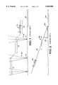
- FIG. 1schematically depicts an aircraft attempting a non-precision landing approach.
- a series of VHF omni-range (VOR) or non-directional beacons (NDBs)typically shown as 10 and 12
- VORVHF omni-range
- NDBsnon-directional beacons
- the pilotuses an altimeter to descend to a lower specified altitude 22.
- the pilotmaintains aircraft 16 at the specified altitude 22 until NDB 12 is reached.
- the pilotflies aircraft 16 to a specified altitude 26 referred to as the decision height.
- the pilotattempts to visually ascertain a runway reference such as the runway itself, runway lights, runway threshold, and the like, within an allotted time. If the pilot visually ascertains a runway reference within the allotted time, the pilot lands aircraft 16. If the pilot does not visually ascertain a runway reference within the allotted time, the landing of aircraft 16 is aborted.
- non-precision landing systemsare widely used, pilot's often desire a greater degree of guidance when making an approach for landing.
- FIG. 2schematically depicts an aircraft attempting a precision landing approach.
- a ground-based transmitter 30radiates a directional signal 32 from the end of a runway 34.
- the signalis transmitted in paired bands at a frequency in the range of 100 to 300 MHz.
- the signalis transmitted over any one of 200 separate frequency channels assigned for use in the 5000 to 5250 MHz range.
- each airport employing a precision landing systemhas a unique signal frequency associated therewith.
- directional signal 32is commonly transmitted at an elevation angle of 3 degrees from the end of a runway 34.
- the path of directional signal 32is referred to as the glideslope.
- the pilotIn a precision landing the pilot follows the glideslope path towards the end of the runway.
- the pilotflies aircraft 36 along the glideslope path until aircraft 36 reaches a specified altitude 38 referred to as the decision height.
- the pilotattempts to visually ascertain a runway reference such as the runway itself, runway lights, runway threshold, and the like. If the pilot visually ascertains a runway reference when at decision height 38 the pilot lands aircraft 36. If the pilot does not visually ascertain a runway reference at decision height 38, landing of aircraft 36 is aborted.
- a precision landing systemprovides both horizontal and vertical guidance to the pilot.
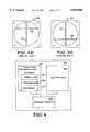
- FIG. 3Ashows a gauge 40 used by a pilot during a precision landing.
- Gauge 40indicates the aircraft's position with respect to beam 32 of Prior Art FIG. 2.
- vertically-arranged indicator bar 42 and horizontally-arranged indicator bar 44indicate the aircraft's position with respect to the center of beam 32.
- the pilotattempts to keep both vertically-arranged indicator bar 42 and horizontally-arranged indicator bar 44 centered as shown in Prior Art FIG. 3A. If the aircraft moves to the right of beam 32, vertically-arranged indicator bar 42 moves to the left as shown in FIG. 3B. To move vertically-arranged indicator bar 42 back towards the center, the pilot must move the aircraft to the left.
- the vertical position of the aircraft with respect to beam 32is also indicated on gauge 40. That is, if the altitude of the aircraft becomes lower than the altitude of beam 32, horizontally-arranged indicator bar 44 rises, as shown in FIG. 3D. To lower horizontally-arranged indicator bar 44 back towards the center, the pilot must increase the altitude of the aircraft. Likewise, if the altitude of the aircraft becomes higher than the altitude of beam 32, horizontally-arranged indicator bar 44 lowers, as shown in FIG. 3E, and the pilot must decrease the altitude of the aircraft to center horizontally-arranged indicator bar 44. Again, such a technique is referred to as "flying towards the needle.” In so doing, the pilot is able to keep the aircraft vertically centered with respect to beam 32.
- a precision landing systemprovides the pilot with both vertical and horizontal guidance.
- precision landing systemsprovide a greater degree of guidance for pilots, precision landing are not available at all landing sites.
- precision landing systemsrequire the construction of a substantial ground based infrastructure at each landing site to provide the required signal transmissions.
- the installation of a precision landing systemis often prohibitively expensive for many landing site owners.
- pilotless landing systemsrequire the construction of a substantial ground based infrastructure at each landing site to provide the required signal transmissions.
- the above objecthas been achieved by an aircraft landing system having a ILS-type graphic readout driven by conventional uncorrected GPS and an altimeter.
- the position determining systemis a satellite-based radio navigation system such as, for example, the Global Positioning System, the Global Orbiting Navigation System, and the like.
- the vertical position of the aircraftis a generated using a baro-altimeter.
- FIG. 1is a Prior Art schematic diagram of an aircraft attempting a non-precision landing approach.
- FIG. 2is a Prior Art schematic diagram of an aircraft attempting a precision landing approach.
- FIG. 4is a schematic diagram of a precision equivalent landing system in accordance with the present claimed invention.
- FIG. 5is a perspective view of the interior of an aircraft equipped with a precision equivalent landing system in accordance with the present claimed invention.
- FIGS. 6A-6Eare front views of a precision equivalent landing system gauge in accordance with the present claimed invention.
- the present precision equivalent landing systemincludes a position determining system 52 having a receiver 54 and a processor 56 integral therewith.
- Receiver 54receives position information signals and transfers the position information signals to processor 56.
- Processor 56then generates position information indicative of the location of the aircraft.
- Position determining system 52generates position information indicating, for example, the latitude, longitude, altitude, and velocity of an aircraft.
- Position determining system 52also accurately determines the time at which the aircraft is at a specific location. In the present embodiment, however, position determining system 52 is used to generate lateral or horizontal position information.
- position determining system 52is used to accurately determine the latitude and longitude of the aircraft in which the present invention is employed. It will be understood by those of ordinary skill in the art that numerous other well known features are not shown for purposes of clarity. Such well known features include but are not limited to, processing logic, user controls, power circuitry, and the like.
- position determining system 52is, for example, a satellite-based radio navigation system. Satellite-based radio navigation systems such as the Global Positioning System (GPS), the Global Orbiting Navigational System (GLONASS), and the like are well suited for use with the present invention. Although such systems are specifically mentioned in the present embodiment, the present invention is also well suited to land-based radio navigation systems such as, for example, LORAN and the like. Additionally, the present invention is also well suited to recording GPS ephemeris data.
- GPSGlobal Positioning System
- GLONASSGlobal Orbiting Navigational System
- the present inventionfurther includes an altimeter 58 for determining the altitude of the aircraft on which the present invention is used.
- altimeter 58is a baro-altimeter which determines altitude based upon barometric pressure.
- the present inventionis also well suited to the use of other altitude sensing devices.
- both position determining system 52 and altimeter 58are communicatively coupled to a graphic display 60.
- graphic display 60is a gauge similar to the gauge used by a pilot during a precision landing.
- the gauge used in the present embodimentincludes a horizontally-arranged indicator bar and a vertically-arranged indicator bar which indicate the aircraft's position with respect to a desired landing approach path.
- a detailed description of the integration of an altimeter and a GPSis found in commonly owned currently pending U.S. patent application Ser. No. 08/414,443 to McBurney et al. filed Mar. 31, 1995, entitled "Use of an Altitude Sensor to Augment Availability of GPS Location Fixes" which is incorporated herein by reference.
- the pilotselects a landing approach path using user controls, not shown in FIG. 4.
- the landing approach pathincludes such information as the latitude, longitude, and elevation of the landing site, the direction or heading from which the aircraft will approach the landing site, and the touchdown point for the aircraft.
- the present precision equivalent landing systemincludes a database 57 having at least one landing approach path for a selected airport stored therein.
- the present inventionis also well suited to having the airport transmit at least one landing approach path to an approaching aircraft.
- the present inventionis further well suited to having the airport instruct the pilot which of numerous landing approach paths stored in database 57 for that specific airport is to be used at that time.
- possible landing approach pathsare stored on, for example, portable database memory cards. Such an embodiment has the advantage of allowing a pilot to purchase or otherwise obtain frequently updated landing approach paths for selected airports.
- database 57includes information regarding the crossing altitudes for particular waypoints along the landing approach.
- the present precision landing systemcalculates the desired altitude for the aircraft as a function of the aircraft's distance from the particular waypoints. The difference between the computed desired altitude and the actual altitude determined by the altimeter is used to drive a glide slope needle on display 60. Therefore, as the pilot descends towards the landing site, display 60 indicates both the aircraft's horizontal and vertical position with respect to the selected landing approach path.
- the present inventionprovides both lateral and vertical landing guidance to the pilot without requiring that the landing site be equipped with an ILS, FAA MLS, or other type of precision landing system.
- gauge 60comprises the graphic display portion of the present invention.
- the size of gauge 60is exaggerated for purposes of clarity.
- User controls located in the cockpitare used to enter or select a landing approach path.
- the present inventionis also well suited to locating gauge 60 at other locations within the cockpit of the aircraft.
- gauge 60includes a vertically-arranged indicator bar 62 and a horizontally-arranged indicator bar 64.
- Vertically-arranged indicator bar 62 and horizontally-arranged indicator bar 64concurrently represent the aircraft's position with respect to previously selected landing approach path.
- the pilotattempts to keep both vertically-arranged indicator bar 62 and horizontally-arranged indicator bar 64 centered as shown in FIG. 6A.
- position determining system 52 of FIG. 4is used to drive vertically-arranged indicator bar 62.
- the present inventioncompares the latitude and longitude of the aircraft, as determined by position determining system 52, with the previously selected landing approach path.
- vertically-arranged indicator bar 62moves to the left as shown in FIG. 6B.
- the pilotmust move the aircraft to the left.
- vertically-arranged indicator bar 62moves to the right as shown in FIG. 6C, and the pilot must move the aircraft to the right to center vertically-arranged indicator bar 62.
- the present inventionallows the pilot is able to keep the aircraft horizontally centered with respect to the selected landing approach path.
- the vertical position of the aircraft with respect to a computed desired altitudeis also shown by gauge 60.
- altimeter 58 of FIG. 4is used to drive horizontally-arranged indicator bar 64. That is, the present invention compares the altitude of the aircraft, as determined by altimeter 58, with the computed desired altitude. Thus, if the altitude of the aircraft becomes lower than the altitude should be according to the landing approach path, horizontally-arranged indicator bar 64 rises as shown in FIG. 6D. To lower horizontally-arranged indicator bar 64 back towards the center, the pilot must increase the altitude of the aircraft. Likewise, if the altitude of the aircraft becomes higher than the altitude should be, horizontally-arranged indicator bar 64 lowers as shown in FIG.
- the present inventionprovides a precision-equivalent landing system which concurrently provides the pilot with both vertical and horizontal guidance to a selected landing approach path. Furthermore, the present invention provides position information in a manner, i.e. gauge 60, which is familiar to pilots.
- position determining system 52determines the latitude and longitude of the aircraft to within approximately 100 meters even when subjected to selected availability (SA) induced error.
- SAselected availability
- the present precision-equivalent landing systemis also well suited for use at landing sites equipped with a differential corrections transmitter. In such an instance, position determining system 52 will determine the latitude and longitude of the aircraft to within approximately 3 meters.
- the present inventionis also well suited to being used in conjunction with improved position determining accuracy provided by the impending WAAS system. Likewise, any vertical position inaccuracy in the baro-altimeter of the present invention does not substantially affect the usefulness of the present precision-equivalent landing system. That is, as the pilot reaches the decision height, a slight difference in actual and reported altitude will not affect the pilot's ability to land or abort the landing of the aircraft.
- gauge 60is recited in the present embodiment, the present invention is also well suited to other types of graphic displays such as, for example, a digital readout, a synthesized voice display, indicator dials, and the like.
- the present precision-equivalent landing systemcan be used at any potential landing site.
- the present precision-equivalent landing systemdoes not require the construction of a substantial ground-based infrastructure at each potential landing site.
- the present precision-equivalent landing systemcan be employed in an aircraft at a cost substantially less than the cost associated with constructing an ILS or FAA MLS precision landing system.
- the present inventionoperates in conjunction with well known and widely used commercial flight computers to guide the pilot to the nearest landing site during an emergency.
- the present inventionwould provide both relative position and altitude of the distressed incoming aircraft with respect to a landing approach path to the nearest landing site.
- the pilotactivates the emergency landing mode by pushing a single button on the flight computer. Once the button is activated, the flight computer will guide the pilot to the nearest landing strip.
Landscapes
- Engineering & Computer Science (AREA)
- Aviation & Aerospace Engineering (AREA)
- Radar, Positioning & Navigation (AREA)
- Remote Sensing (AREA)
- Physics & Mathematics (AREA)
- General Physics & Mathematics (AREA)
- Automation & Control Theory (AREA)
- Traffic Control Systems (AREA)
- Position Fixing By Use Of Radio Waves (AREA)
Abstract
Description
This invention relates to aircraft landing systems. Specifically, the present invention relates to precision landing systems.
Two basic types of aircraft landing systems, i.e. non-precision and precision, are well known in the art. A precision landing system provides both horizontal and vertical guidance to the pilot, whereas a non-precision landing system does not directly provide vertical guidance. Prior Art FIG. 1 schematically depicts an aircraft attempting a non-precision landing approach. In a non-precision landing system, a series of VHF omni-range (VOR) or non-directional beacons (NDBs), typically shown as 10 and 12, direct a pilot through a respective series of descent or step down altitudes. More specifically, a pilot maintains a first altitude 14 until theaircraft 16 passes through vertical fan-shaped beams aircraft 16 passes throughbeam 18, the pilot uses an altimeter to descend to a lower specifiedaltitude 22. The pilot maintainsaircraft 16 at the specifiedaltitude 22 until NDB 12 is reached. Asaircraft 16 approaches the runway 24, the pilot fliesaircraft 16 to a specifiedaltitude 26 referred to as the decision height. While flying at the decision height, the pilot attempts to visually ascertain a runway reference such as the runway itself, runway lights, runway threshold, and the like, within an allotted time. If the pilot visually ascertains a runway reference within the allotted time, thepilot lands aircraft 16. If the pilot does not visually ascertain a runway reference within the allotted time, the landing ofaircraft 16 is aborted. Although non-precision landing systems are widely used, pilot's often desire a greater degree of guidance when making an approach for landing.
Prior Art FIG. 2 schematically depicts an aircraft attempting a precision landing approach. In a precision landing system, a ground-basedtransmitter 30 radiates adirectional signal 32 from the end of arunway 34. In an ILS-type system the signal is transmitted in paired bands at a frequency in the range of 100 to 300 MHz. In an FAA MLS-type precision landing system, the signal is transmitted over any one of 200 separate frequency channels assigned for use in the 5000 to 5250 MHz range. Typically, each airport employing a precision landing system has a unique signal frequency associated therewith. As shown in Prior Art FIG. 2, in a precision landing system,directional signal 32 is commonly transmitted at an elevation angle of 3 degrees from the end of arunway 34. The path ofdirectional signal 32 is referred to as the glideslope. In a precision landing the pilot follows the glideslope path towards the end of the runway. Asaircraft 36 approaches therunway 34, the pilot fliesaircraft 36 along the glideslope path untilaircraft 36 reaches a specifiedaltitude 38 referred to as the decision height. Onceaircraft 36 reachesdecision height 38, the pilot attempts to visually ascertain a runway reference such as the runway itself, runway lights, runway threshold, and the like. If the pilot visually ascertains a runway reference when atdecision height 38 thepilot lands aircraft 36. If the pilot does not visually ascertain a runway reference atdecision height 38, landing ofaircraft 36 is aborted. Thus, unlike a non-precision landing system, a precision landing system provides both horizontal and vertical guidance to the pilot.
Prior Art FIG. 3A, shows agauge 40 used by a pilot during a precision landing. Gauge 40 indicates the aircraft's position with respect tobeam 32 of Prior Art FIG. 2. Specifically, vertically-arrangedindicator bar 42 and horizontally-arrangedindicator bar 44 indicate the aircraft's position with respect to the center ofbeam 32. When usinggauge 40, the pilot attempts to keep both vertically-arrangedindicator bar 42 and horizontally-arrangedindicator bar 44 centered as shown in Prior Art FIG. 3A. If the aircraft moves to the right ofbeam 32, vertically-arrangedindicator bar 42 moves to the left as shown in FIG. 3B. To move vertically-arrangedindicator bar 42 back towards the center, the pilot must move the aircraft to the left. Likewise, if the aircraft moves to the left ofbeam 32, vertically-arrangedindicator bar 42 moves to the right, as shown in FIG. 3C and the pilot must move the aircraft to the right to center vertically-arrangedindicator bar 42. Such a technique is referred to as "flying towards the needle." In so doing, the pilot is able to keep the aircraft horizontally centered with respect tobeam 32.
The vertical position of the aircraft with respect tobeam 32 is also indicated ongauge 40. That is, if the altitude of the aircraft becomes lower than the altitude ofbeam 32, horizontally-arrangedindicator bar 44 rises, as shown in FIG. 3D. To lower horizontally-arrangedindicator bar 44 back towards the center, the pilot must increase the altitude of the aircraft. Likewise, if the altitude of the aircraft becomes higher than the altitude ofbeam 32, horizontally-arrangedindicator bar 44 lowers, as shown in FIG. 3E, and the pilot must decrease the altitude of the aircraft to center horizontally-arrangedindicator bar 44. Again, such a technique is referred to as "flying towards the needle." In so doing, the pilot is able to keep the aircraft vertically centered with respect tobeam 32. Thus, a precision landing system provides the pilot with both vertical and horizontal guidance. Although precision landing systems provide a greater degree of guidance for pilots, precision landing are not available at all landing sites. Furthermore, precision landing systems require the construction of a substantial ground based infrastructure at each landing site to provide the required signal transmissions. As an additional drawback, the installation of a precision landing system is often prohibitively expensive for many landing site owners.
Some prior art landing systems, such as those worked on by Clark Cohen at Stanford University, are attempting to achieve fully automated pilotless landings. However, like other prior art landing systems, pilotless landing systems require the construction of a substantial ground based infrastructure at each landing site to provide the required signal transmissions.
Thus, a need exists for a precision equivalent landing system which is universally applicable, a precision equivalent landing system which does not require the construction of a substantial ground-based infrastructure at each potential landing site, and a precision equivalent landing system which is affordable.
It is therefore an object of the present invention to provide a precision equivalent landing system which is universally applicable, a precision equivalent landing system which does not require the construction of a substantial ground-based infrastructure at each potential landing site, and a precision equivalent landing system which is affordable. The above object has been achieved by an aircraft landing system having a ILS-type graphic readout driven by conventional uncorrected GPS and an altimeter.
In the present invention, a precision equivalent landing system is disclosed. In one embodiment, a position determining system is coupled to an aircraft. The position determining system generates lateral position information of the aircraft with respect to a landing approach path. An altimeter is also coupled to the aircraft. The altimeter generates vertical position information for the aircraft. A graphic display disposed within the aircraft concurrently displays a visual representation of the lateral position of the aircraft with respect to the landing approach path and the vertical position of the aircraft. In so doing, the present invention provides both relative position and altitude of an incoming aircraft with respect to a landing approach path. Thus, the present invention provides a precision equivalent landing system without requiring the equipment and expense associated with ILS or FAA MLS precision landing systems.
In one embodiment, the position determining system is a satellite-based radio navigation system such as, for example, the Global Positioning System, the Global Orbiting Navigation System, and the like.
In one embodiment of the present invention, the vertical position of the aircraft is a generated using a baro-altimeter.
These and other objects and advantages of the present invention will no doubt become obvious to those of ordinary skill in the art after having read the following detailed description of the preferred embodiments which are illustrated in the various drawing figures.
The accompanying drawings, which are incorporated in and form a part of this specification, illustrate embodiments of the invention and, together with the description, serve to explain the principles of the invention:
FIG. 1 is a Prior Art schematic diagram of an aircraft attempting a non-precision landing approach.
FIG. 2 is a Prior Art schematic diagram of an aircraft attempting a precision landing approach.
FIGS. 3A-3E are front views of a Prior Art gauge used by a pilot during a precision landing.
FIG. 4 is a schematic diagram of a precision equivalent landing system in accordance with the present claimed invention.
FIG. 5 is a perspective view of the interior of an aircraft equipped with a precision equivalent landing system in accordance with the present claimed invention.
FIGS. 6A-6E are front views of a precision equivalent landing system gauge in accordance with the present claimed invention.
Reference will now be made in detail to the preferred embodiments of the invention, examples of which are illustrated in the accompanying drawings. While the invention will be described in conjunction with the preferred embodiments, it will be understood that they are not intended to limit the invention to these embodiments. On the contrary, the invention is intended to cover alternatives, modifications and equivalents, which may be included within the spirit and scope of the invention as defined by the appended claims. Furthermore, in the following detailed description of the present invention, numerous specific details are set forth in order to provide a thorough understanding of the present invention. However, it will be obvious to one of ordinary skill in the art that the present invention may be practiced without these specific details. In other instances, well known methods, procedures, components, and circuits have not been described in detail as not to unnecessarily obscure aspects of the present invention.
With reference now to FIG. 4, a schematic diagram of one embodiment of a precision equivalent landing system in accordance with the present claimed invention is shown. As shown in FIG. 4, the present precision equivalent landing system includes aposition determining system 52 having areceiver 54 and aprocessor 56 integral therewith.Receiver 54 receives position information signals and transfers the position information signals toprocessor 56.Processor 56 then generates position information indicative of the location of the aircraft.Position determining system 52 generates position information indicating, for example, the latitude, longitude, altitude, and velocity of an aircraft.Position determining system 52 also accurately determines the time at which the aircraft is at a specific location. In the present embodiment, however,position determining system 52 is used to generate lateral or horizontal position information. That is,position determining system 52 is used to accurately determine the latitude and longitude of the aircraft in which the present invention is employed. It will be understood by those of ordinary skill in the art that numerous other well known features are not shown for purposes of clarity. Such well known features include but are not limited to, processing logic, user controls, power circuitry, and the like. In the present invention,position determining system 52 is, for example, a satellite-based radio navigation system. Satellite-based radio navigation systems such as the Global Positioning System (GPS), the Global Orbiting Navigational System (GLONASS), and the like are well suited for use with the present invention. Although such systems are specifically mentioned in the present embodiment, the present invention is also well suited to land-based radio navigation systems such as, for example, LORAN and the like. Additionally, the present invention is also well suited to recording GPS ephemeris data.
With reference still to FIG. 4, the present invention further includes analtimeter 58 for determining the altitude of the aircraft on which the present invention is used. In the present embodiment,altimeter 58 is a baro-altimeter which determines altitude based upon barometric pressure. Although such an altimeter is used in the present embodiment, the present invention is also well suited to the use of other altitude sensing devices. As shown in FIG. 4, bothposition determining system 52 andaltimeter 58 are communicatively coupled to agraphic display 60. In the present embodiment,graphic display 60 is a gauge similar to the gauge used by a pilot during a precision landing. That is, the gauge used in the present embodiment includes a horizontally-arranged indicator bar and a vertically-arranged indicator bar which indicate the aircraft's position with respect to a desired landing approach path. A detailed description of the integration of an altimeter and a GPS is found in commonly owned currently pending U.S. patent application Ser. No. 08/414,443 to McBurney et al. filed Mar. 31, 1995, entitled "Use of an Altitude Sensor to Augment Availability of GPS Location Fixes" which is incorporated herein by reference.
To use the present invention, as the pilot nears the desired landing site, the pilot selects a landing approach path using user controls, not shown in FIG. 4. The landing approach path includes such information as the latitude, longitude, and elevation of the landing site, the direction or heading from which the aircraft will approach the landing site, and the touchdown point for the aircraft. In the present embodiment, the present precision equivalent landing system includes adatabase 57 having at least one landing approach path for a selected airport stored therein. The present invention is also well suited to having the airport transmit at least one landing approach path to an approaching aircraft. The present invention is further well suited to having the airport instruct the pilot which of numerous landing approach paths stored indatabase 57 for that specific airport is to be used at that time. In yet another embodiment, possible landing approach paths are stored on, for example, portable database memory cards. Such an embodiment has the advantage of allowing a pilot to purchase or otherwise obtain frequently updated landing approach paths for selected airports.
In the present embodiment,database 57 includes information regarding the crossing altitudes for particular waypoints along the landing approach. The present precision landing system calculates the desired altitude for the aircraft as a function of the aircraft's distance from the particular waypoints. The difference between the computed desired altitude and the actual altitude determined by the altimeter is used to drive a glide slope needle ondisplay 60. Therefore, as the pilot descends towards the landing site,display 60 indicates both the aircraft's horizontal and vertical position with respect to the selected landing approach path. Thus, the present invention provides both lateral and vertical landing guidance to the pilot without requiring that the landing site be equipped with an ILS, FAA MLS, or other type of precision landing system.
With reference next to FIG. 5, a perspective view of the interior of an aircraft equipped with the present precision equivalent landing system is shown. In FIG. 5, gauge 60 comprises the graphic display portion of the present invention. The size ofgauge 60 is exaggerated for purposes of clarity. User controls located in the cockpit are used to enter or select a landing approach path. The present invention is also well suited to locatinggauge 60 at other locations within the cockpit of the aircraft.
With reference next to a FIG. 6, a detailed schematic view ofgauge 60 of the present invention is shown. In the present embodiment, gauge 60 includes a vertically-arrangedindicator bar 62 and a horizontally-arrangedindicator bar 64. Vertically-arrangedindicator bar 62 and horizontally-arrangedindicator bar 64 concurrently represent the aircraft's position with respect to previously selected landing approach path. As in an ILS or FAA MLS precision landing system, the pilot attempts to keep both vertically-arrangedindicator bar 62 and horizontally-arrangedindicator bar 64 centered as shown in FIG. 6A. In the present invention,position determining system 52 of FIG. 4 is used to drive vertically-arrangedindicator bar 62. That is, the present invention compares the latitude and longitude of the aircraft, as determined byposition determining system 52, with the previously selected landing approach path. Thus, if the aircraft moves to the right of the landing approach path, vertically-arrangedindicator bar 62 moves to the left as shown in FIG. 6B. To move vertically-arrangedindicator bar 62 back towards center, the pilot must move the aircraft to the left. Likewise, if the aircraft moves to the left of the landing approach path, vertically-arrangedindicator bar 62 moves to the right as shown in FIG. 6C, and the pilot must move the aircraft to the right to center vertically-arrangedindicator bar 62. In so doing, the present invention allows the pilot is able to keep the aircraft horizontally centered with respect to the selected landing approach path.
The vertical position of the aircraft with respect to a computed desired altitude is also shown bygauge 60. In the present invention,altimeter 58 of FIG. 4 is used to drive horizontally-arrangedindicator bar 64. That is, the present invention compares the altitude of the aircraft, as determined byaltimeter 58, with the computed desired altitude. Thus, if the altitude of the aircraft becomes lower than the altitude should be according to the landing approach path, horizontally-arrangedindicator bar 64 rises as shown in FIG. 6D. To lower horizontally-arrangedindicator bar 64 back towards the center, the pilot must increase the altitude of the aircraft. Likewise, if the altitude of the aircraft becomes higher than the altitude should be, horizontally-arrangedindicator bar 64 lowers as shown in FIG. 6E, and the pilot must then decrease the altitude of the aircraft to center horizontally-arrangedindicator bar 64. In so doing, the pilot is able to keep the altitude of the aircraft approximately equal to the computed desired altitude along the landing approach path. Thus, the present invention provides a precision-equivalent landing system which concurrently provides the pilot with both vertical and horizontal guidance to a selected landing approach path. Furthermore, the present invention provides position information in a manner, i.e.gauge 60, which is familiar to pilots.
In the present embodiment,position determining system 52 determines the latitude and longitude of the aircraft to within approximately 100 meters even when subjected to selected availability (SA) induced error. However, such error does not substantially affect the usefulness of the present precision-equivalent landing system. That is, as the pilot reaches the decision height during, for example, a category 1 landing, the pilot will still have ample time to alter the position of the aircraft to correct for SA induced error. Thus, the present invention maintains its utility even without differential corrections. However, the present precision-equivalent landing system is also well suited for use at landing sites equipped with a differential corrections transmitter. In such an instance,position determining system 52 will determine the latitude and longitude of the aircraft to within approximately 3 meters. The present invention is also well suited to being used in conjunction with improved position determining accuracy provided by the impending WAAS system. Likewise, any vertical position inaccuracy in the baro-altimeter of the present invention does not substantially affect the usefulness of the present precision-equivalent landing system. That is, as the pilot reaches the decision height, a slight difference in actual and reported altitude will not affect the pilot's ability to land or abort the landing of the aircraft.
Furthermore, although agauge 60 is recited in the present embodiment, the present invention is also well suited to other types of graphic displays such as, for example, a digital readout, a synthesized voice display, indicator dials, and the like.
Thus, the present precision-equivalent landing system can be used at any potential landing site. The present precision-equivalent landing system does not require the construction of a substantial ground-based infrastructure at each potential landing site. As an additional benefit, the present precision-equivalent landing system can be employed in an aircraft at a cost substantially less than the cost associated with constructing an ILS or FAA MLS precision landing system.
In another embodiment, the present invention operates in conjunction with well known and widely used commercial flight computers to guide the pilot to the nearest landing site during an emergency. In such an embodiment, the present invention would provide both relative position and altitude of the distressed incoming aircraft with respect to a landing approach path to the nearest landing site. In the present embodiment, the pilot activates the emergency landing mode by pushing a single button on the flight computer. Once the button is activated, the flight computer will guide the pilot to the nearest landing strip.
The foregoing descriptions of specific embodiments of the present invention have been presented for purposes of illustration and description. They are not intended to be exhaustive or to limit the invention to the precise forms disclosed, and obviously many modifications and variations are possible in light of the above teaching. The embodiments were chosen and described in order to best explain the principles of the invention and its practical application, to thereby enable others skilled in the art to best utilize the invention and various embodiments with various modifications as are suited to the particular use contemplated. It is intended that the scope of the invention be defined by the claims appended hereto and their equivalents.
Claims (17)
1. A precision equivalent landing system comprising:
a position determining system adapted to be coupled to an aircraft, said position determining system generating lateral position information of said aircraft with respect to a landing approach path;
an altimeter adapted to be coupled to said aircraft, said altimeter adapted to generate vertical position information of said aircraft with respect to said landing approach path, said altimeter adapted to provide said vertical position information without receiving second vertical position information from said position determining system; and
a graphic display adapted to be disposed within said aircraft for concurrently displaying a visual representation of said lateral position of said aircraft with respect to said landing approach path and said vertical position of said aircraft with respect to said landing approach path, wherein said precision equivalent landing system provides said visual representation of said lateral position of said aircraft with respect to said landing approach path and said vertical position of said aircraft with respect to said landing approach path without requiring ground-based infrastructure at or near said landing approach path.
2. The precision equivalent landing system of claim 1 wherein said position determining system is a satellite-based radio navigation system.
3. The precision equivalent landing system of claim 2 wherein said satellite-based radio navigation system consists of the Global Positioning System.
4. The precision equivalent landing system of claim 2 wherein said satellite-based radio navigation system consists of the Global Orbiting Navigation System.
5. The precision equivalent landing system of claim 1 wherein said position determining system further includes:
a signal receiver; and
a signal processor having an input coupled to said signal receiver, said signal processor generating said lateral position information of said aircraft with respect to said landing approach path from signals received at said input from said signal receiver, said signal processor having an output coupled to said graphic display, said output providing said lateral position information of said aircraft with respect to said landing approach path from said signal processor to said graphic display.
6. The precision equivalent landing system of claim 1 wherein said altimeter is comprised of a baro-altimeter.
7. A precision equivalent aircraft landing method comprising the steps of:
generating lateral position information of an aircraft with respect to a landing approach path, said lateral position information determined by a position determining system coupled to said aircraft;
generating vertical position information of said aircraft with respect to said landing approach path, said vertical position information generated by an altimeter coupled to said aircraft, said altimeter adapted to provide said vertical position information of without receiving second vertical position information from said position determining system; and
concurrently displaying, on a graphic display disposed within said aircraft, a visual representation of said lateral position of said aircraft with respect to said landing approach path and said vertical position of said aircraft with respect to said landing approach path, wherein said precision equivalent aircraft landing method provides said visual representation of said lateral position of said aircraft with respect to said landing approach path and said vertical position of said aircraft with respect to said landing approach path without requiring ground-based infrastructure at or near said landing approach path.
8. The precision equivalent aircraft landing method as recited in claim 7 wherein said step of generating lateral position information of said aircraft further includes generating said lateral position information of said aircraft using a satellite-based radio navigation position determining system.
9. The precision equivalent aircraft landing method as recited in claim 8 wherein said step of generating lateral position information of said aircraft using a satellite-based radio navigation position determining system further includes the step of generating said lateral position information of said aircraft using the Global Positioning System.
10. The precision equivalent aircraft landing method as recited in claim 8 wherein said step of generating lateral position information of said aircraft with respect to said landing approach path using a satellite-based radio navigation position determining system further includes the step of generating said lateral position information of said aircraft using the Global Orbiting Navigation System.
11. The precision equivalent aircraft landing method as recited in claim 7 wherein said step of generating lateral position information of said aircraft with respect to said landing approach path further includes the steps of:
receiving radio navigation signals at a signal receiver of said position determining system,
processing said radio navigation signals using a signal processor of said position determining system to generate said lateral position information of said aircraft with respect to said landing site, said radio navigation signals received from said signal receiver at an input of said signal processor; and
providing said lateral position information of said aircraft with respect to said landing approach path to said graphic display via an output of said signal processor.
12. The precision equivalent aircraft landing method as recited in claim 7 wherein said step of generating vertical position information of said aircraft with respect to said landing approach path further includes the step of:
generating vertical position information of said aircraft with respect to said landing approach path using a baro-altimeter.
13. An ILS equivalent aircraft landing apparatus comprising:
a satellite-based position determining system adapted to be coupled to an aircraft, said satellite position determining system adapted to generate lateral position information of said aircraft with respect to a landing approach path;
an altimeter adapted to be coupled to said aircraft, said altimeter adapted to generate vertical position information of said aircraft with respect to said landing approach path, said altimeter adapted to provide said vertical position information without receiving second vertical position information from said position determining system; and
a graphic display for concurrently displaying a visual representation of said lateral position of said aircraft with respect to said landing approach path and said vertical position of said aircraft with respect to said landing approach path, wherein said ILS equivalent aircraft landing apparatus provides said visual representation of said lateral position of said aircraft with respect to said landing approach path and said vertical position of said aircraft with respect to said landing approach path without requiring ground-based infrastructure at or near said landing approach path.
14. The ILS equivalent aircraft landing apparatus of claim 13 wherein said satellite-based position determining system consists of the Global Positioning System.
15. The ILS equivalent aircraft landing apparatus of claim 13 wherein said satellite-based position determining system consists of the Global Orbiting Navigation System.
16. The ILS equivalent aircraft landing apparatus of claim 13 wherein said satellite-based position determining system further includes:
a signal receiver; and
a signal processor having an input coupled to said signal receiver, said signal processor generating said lateral position information of said aircraft with respect to said landing approach path from signals received at said input from said signal receiver, said signal processor having an output coupled to said graphic display, said output providing said lateral position information of said aircraft with respect to said landing approach path from said signal processor to said graphic display.
17. The ILS equivalent aircraft landing apparatus of claim 13 wherein said altimeter is comprised of a baro-altimeter.
Priority Applications (1)
| Application Number | Priority Date | Filing Date | Title |
|---|---|---|---|
| US08/615,837US5820080A (en) | 1996-03-14 | 1996-03-14 | Precision equivalent landing system using gps and an altimeter |
Applications Claiming Priority (1)
| Application Number | Priority Date | Filing Date | Title |
|---|---|---|---|
| US08/615,837US5820080A (en) | 1996-03-14 | 1996-03-14 | Precision equivalent landing system using gps and an altimeter |
Publications (1)
| Publication Number | Publication Date |
|---|---|
| US5820080Atrue US5820080A (en) | 1998-10-13 |
Family
ID=24467026
Family Applications (1)
| Application Number | Title | Priority Date | Filing Date |
|---|---|---|---|
| US08/615,837Expired - LifetimeUS5820080A (en) | 1996-03-14 | 1996-03-14 | Precision equivalent landing system using gps and an altimeter |
Country Status (1)
| Country | Link |
|---|---|
| US (1) | US5820080A (en) |
Cited By (45)
| Publication number | Priority date | Publication date | Assignee | Title |
|---|---|---|---|---|
| US5952961A (en)* | 1998-01-30 | 1999-09-14 | Trimble Navigation Limited | Low observable radar augmented GPS navigation system |
| WO2001011383A1 (en)* | 1999-08-06 | 2001-02-15 | Bell Helicopter Textron Inc. | Method and system for creating an approach to a position on the ground from a location above the ground |
| US6205377B1 (en) | 1999-04-27 | 2001-03-20 | Trimble Navigation Ltd | Method for navigation of moving platform by using satellite data supplemented by satellite-calibrated baro data |
| US6308116B1 (en)* | 2000-02-11 | 2001-10-23 | Rockwell Collins | System and method for integrating LNAV and VNAV with autopilots for existing aircraft |
| US6381540B1 (en) | 1999-11-01 | 2002-04-30 | Garmin Corporation | GPS device with compass and altimeter and method for displaying navigation information |
| US6522298B1 (en) | 2001-04-12 | 2003-02-18 | Garmin Ltd. | Device and method for calibrating and improving the accuracy of barometric altimeters with GPS-derived altitudes |
| DE10141595A1 (en)* | 2001-08-24 | 2003-03-13 | Guenter Blaschke | Hybrid instruments landing systems for aircraft |
| US6549829B1 (en)* | 2001-10-31 | 2003-04-15 | The Boeing Company | Skipping filter for inertially augmented landing system |
| US6600977B2 (en)* | 2000-08-18 | 2003-07-29 | Honeywell International Inc. | Glideslope monitor for aircraft |
| US20030171856A1 (en)* | 2002-03-07 | 2003-09-11 | Wilf Herbert S. | Global positioning system readout of recommended altitude in aircraft landing pattern |
| US20040068372A1 (en)* | 2002-10-03 | 2004-04-08 | Ybarra Kathryn W. | Threat avoidance system and methods using adjustments to built-in values |
| US6735542B1 (en) | 2001-05-09 | 2004-05-11 | Garmin Ltd. | Method and apparatus for calculating altitude based on barometric and GPS measurements |
| EP1459979A1 (en)* | 2003-03-19 | 2004-09-22 | Airbus France | Method and device for determining at least one information regarding the vertical position of an aircraft |
| EP1460504A1 (en)* | 2003-03-19 | 2004-09-22 | Airbus France | System for piloting an aircraft, at least for piloting the aircraft during a non precision approach to landing |
| US6798378B1 (en)* | 2002-11-22 | 2004-09-28 | Garmin Ltd. | Device and method for displaying track characteristics |
| US20040245408A1 (en)* | 2003-03-19 | 2004-12-09 | Airbus France | Method and device to assist in the piloting of an aircraft in a non-precision approach during a landing phase |
| FR2857330A1 (en)* | 2003-07-07 | 2005-01-14 | Daniel Albert Lemascon | Aircraft landing permitting method for e.g. private aviation, involves displaying horizontal line, representing aircraft plan of approach, displacing vertically towards top or bottom if approach is far or near respectively |
| US20050023409A1 (en)* | 2003-07-28 | 2005-02-03 | Moshe Shnaps | System and method for munition impact assessment |
| US6862525B1 (en) | 1999-11-01 | 2005-03-01 | Garmin Corporation | GPS device with compass and altimeter and method for displaying navigation information |
| US20050182530A1 (en)* | 2004-02-13 | 2005-08-18 | Murphy Timothy A. | Global navigation satellite system landing systems and methods |
| EP1589351A1 (en) | 2004-04-22 | 2005-10-26 | Airbus France | Method and apparatus for landing aids of an aircraft on a runway |
| US20070279254A1 (en)* | 2006-01-11 | 2007-12-06 | Airbus France | Method and device to assist in the piloting of an aircraft |
| US20080004756A1 (en)* | 2006-06-02 | 2008-01-03 | Innovative Solutions & Support, Inc. | Method and apparatus for display of current aircraft position and operating parameters on a graphically-imaged chart |
| US20080154442A1 (en)* | 2006-12-21 | 2008-06-26 | Patrick Ralf Wipplinger | Methods and systems for displaying electronic enroute maps |
| US20080172149A1 (en)* | 2005-07-13 | 2008-07-17 | Airbus France | Device For Assisting a Vertical Guidance Approach For Aircraft |
| EP1980869A2 (en) | 2007-04-10 | 2008-10-15 | Honeywell International Inc. | Navigation guidance for aircraft approach and landing |
| EP2146332A2 (en) | 2008-07-15 | 2010-01-20 | Astrium GmbH | Method for automatically detecting a runway |
| US20100036550A1 (en)* | 2008-08-05 | 2010-02-11 | Honeywell International Inc. | Systems and methods for improving pilot situational awareness during landing |
| US7908080B2 (en) | 2004-12-31 | 2011-03-15 | Google Inc. | Transportation routing |
| US20110106345A1 (en)* | 2009-11-03 | 2011-05-05 | Takacs Robert S | Low visibility landing system |
| US7965225B1 (en) | 2008-07-02 | 2011-06-21 | Rockwell Collins, Inc. | Radar antenna stabilization enhancement using vertical beam switching |
| US20110264312A1 (en)* | 2010-04-21 | 2011-10-27 | Spinelli Charles B | Determining Landing Sites for Aircraft |
| US8077078B1 (en)* | 2008-07-25 | 2011-12-13 | Rockwell Collins, Inc. | System and method for aircraft altitude measurement using radar and known runway position |
| US8558731B1 (en) | 2008-07-02 | 2013-10-15 | Rockwell Collins, Inc. | System for and method of sequential lobing using less than full aperture antenna techniques |
| EP2173613B1 (en)* | 2007-08-09 | 2014-02-26 | LTA Corporation | Lenticular airship and associated controls |
| US9019145B1 (en) | 2011-07-14 | 2015-04-28 | Rockwell Collins, Inc. | Ground clutter rejection for weather radar |
| US9024805B1 (en) | 2012-09-26 | 2015-05-05 | Rockwell Collins, Inc. | Radar antenna elevation error estimation method and apparatus |
| US9354633B1 (en) | 2008-10-31 | 2016-05-31 | Rockwell Collins, Inc. | System and method for ground navigation |
| US9384586B1 (en) | 2013-04-05 | 2016-07-05 | Rockwell Collins, Inc. | Enhanced flight vision system and method with radar sensing and pilot monitoring display |
| US9733349B1 (en) | 2007-09-06 | 2017-08-15 | Rockwell Collins, Inc. | System for and method of radar data processing for low visibility landing applications |
| US9939526B2 (en) | 2007-09-06 | 2018-04-10 | Rockwell Collins, Inc. | Display system and method using weather radar sensing |
| US10228460B1 (en) | 2016-05-26 | 2019-03-12 | Rockwell Collins, Inc. | Weather radar enabled low visibility operation system and method |
| US10353068B1 (en) | 2016-07-28 | 2019-07-16 | Rockwell Collins, Inc. | Weather radar enabled offshore operation system and method |
| US10705201B1 (en) | 2015-08-31 | 2020-07-07 | Rockwell Collins, Inc. | Radar beam sharpening system and method |
| US10928510B1 (en) | 2014-09-10 | 2021-02-23 | Rockwell Collins, Inc. | System for and method of image processing for low visibility landing applications |
Citations (7)
| Publication number | Priority date | Publication date | Assignee | Title |
|---|---|---|---|---|
| US4326189A (en)* | 1979-04-23 | 1982-04-20 | Crane Carl J | Aircraft control/guidance display and mechanism for enroute and landing utility |
| US5136301A (en)* | 1989-08-30 | 1992-08-04 | Rockwell International Corporation | Primary flight display system having a vertical linear altimeter |
| US5210540A (en)* | 1991-06-18 | 1993-05-11 | Pioneer Electronic Corporation | Global positioning system |
| US5289185A (en)* | 1990-09-05 | 1994-02-22 | Aerospatiale Societe Nationale Industrielle | Process for displaying flying aid symbols on a screen on board an aircraft |
| US5361212A (en)* | 1992-11-02 | 1994-11-01 | Honeywell Inc. | Differential GPS landing assistance system |
| US5493694A (en)* | 1993-11-08 | 1996-02-20 | Trimble Navigation Limited | Fast response system for a fleet of vehicles |
| US5574649A (en)* | 1991-09-27 | 1996-11-12 | Levy; Nessim I. | Position-locating method and apparatus including corrections for elevational changes |
- 1996
- 1996-03-14USUS08/615,837patent/US5820080A/ennot_activeExpired - Lifetime
Patent Citations (7)
| Publication number | Priority date | Publication date | Assignee | Title |
|---|---|---|---|---|
| US4326189A (en)* | 1979-04-23 | 1982-04-20 | Crane Carl J | Aircraft control/guidance display and mechanism for enroute and landing utility |
| US5136301A (en)* | 1989-08-30 | 1992-08-04 | Rockwell International Corporation | Primary flight display system having a vertical linear altimeter |
| US5289185A (en)* | 1990-09-05 | 1994-02-22 | Aerospatiale Societe Nationale Industrielle | Process for displaying flying aid symbols on a screen on board an aircraft |
| US5210540A (en)* | 1991-06-18 | 1993-05-11 | Pioneer Electronic Corporation | Global positioning system |
| US5574649A (en)* | 1991-09-27 | 1996-11-12 | Levy; Nessim I. | Position-locating method and apparatus including corrections for elevational changes |
| US5361212A (en)* | 1992-11-02 | 1994-11-01 | Honeywell Inc. | Differential GPS landing assistance system |
| US5493694A (en)* | 1993-11-08 | 1996-02-20 | Trimble Navigation Limited | Fast response system for a fleet of vehicles |
Cited By (85)
| Publication number | Priority date | Publication date | Assignee | Title |
|---|---|---|---|---|
| US5952961A (en)* | 1998-01-30 | 1999-09-14 | Trimble Navigation Limited | Low observable radar augmented GPS navigation system |
| US6205377B1 (en) | 1999-04-27 | 2001-03-20 | Trimble Navigation Ltd | Method for navigation of moving platform by using satellite data supplemented by satellite-calibrated baro data |
| WO2001011383A1 (en)* | 1999-08-06 | 2001-02-15 | Bell Helicopter Textron Inc. | Method and system for creating an approach to a position on the ground from a location above the ground |
| US6216065B1 (en)* | 1999-08-06 | 2001-04-10 | Bell Helicopter Textron Inc. | Method and system for creating an approach to a position on the ground from a location above the ground |
| US6381540B1 (en) | 1999-11-01 | 2002-04-30 | Garmin Corporation | GPS device with compass and altimeter and method for displaying navigation information |
| US6434485B1 (en) | 1999-11-01 | 2002-08-13 | Garmin Corporation | GPS device with compass and altimeter and method for displaying navigation information |
| US6529827B1 (en) | 1999-11-01 | 2003-03-04 | Garmin Corporation | GPS device with compass and altimeter and method for displaying navigation information |
| US6862525B1 (en) | 1999-11-01 | 2005-03-01 | Garmin Corporation | GPS device with compass and altimeter and method for displaying navigation information |
| US6845323B1 (en) | 1999-11-01 | 2005-01-18 | Garmin Corporation | GPS device with compass and altimeter and method for displaying navigation information |
| US6308116B1 (en)* | 2000-02-11 | 2001-10-23 | Rockwell Collins | System and method for integrating LNAV and VNAV with autopilots for existing aircraft |
| US6600977B2 (en)* | 2000-08-18 | 2003-07-29 | Honeywell International Inc. | Glideslope monitor for aircraft |
| US6768449B1 (en) | 2001-04-12 | 2004-07-27 | Garmin Ltd. | Device and method for calibrating and improving the accuracy of barometric altimeters with GPS-derived altitudes |
| US6522298B1 (en) | 2001-04-12 | 2003-02-18 | Garmin Ltd. | Device and method for calibrating and improving the accuracy of barometric altimeters with GPS-derived altitudes |
| US7142152B2 (en) | 2001-04-12 | 2006-11-28 | Garmin Ltd. | Device and method for calibrating and improving the accuracy of barometric altimeters with GPS-derived altitudes |
| US7429948B2 (en) | 2001-04-12 | 2008-09-30 | Garmin Ltd. | Device and method for calibrating and improving the accuracy of barometric altimeters with GPS-derived altitudes |
| US20040196176A1 (en)* | 2001-04-12 | 2004-10-07 | Garmin Ltd., A Cayman Islands Corporation | Device and method for calibrating and improving the accuracy of barometric altimeters with GPS-derived altitudes |
| US20070040732A1 (en)* | 2001-04-12 | 2007-02-22 | Garmin Ltd. | Device and method for calibrating and improving the accuracy of barometric altimeters with gps-derived altitudes |
| US6735542B1 (en) | 2001-05-09 | 2004-05-11 | Garmin Ltd. | Method and apparatus for calculating altitude based on barometric and GPS measurements |
| DE10141595A1 (en)* | 2001-08-24 | 2003-03-13 | Guenter Blaschke | Hybrid instruments landing systems for aircraft |
| US6549829B1 (en)* | 2001-10-31 | 2003-04-15 | The Boeing Company | Skipping filter for inertially augmented landing system |
| US20030171856A1 (en)* | 2002-03-07 | 2003-09-11 | Wilf Herbert S. | Global positioning system readout of recommended altitude in aircraft landing pattern |
| US20070198143A1 (en)* | 2002-10-03 | 2007-08-23 | Ybarra Kathryn W | Threat avoidance system and methods using adjustments to built-in values |
| US7437245B2 (en) | 2002-10-03 | 2008-10-14 | Aviation Communication & Surveillance Systems, Llc | Threat avoidance system and methods using adjustments to built-in values |
| US20040068372A1 (en)* | 2002-10-03 | 2004-04-08 | Ybarra Kathryn W. | Threat avoidance system and methods using adjustments to built-in values |
| US6798378B1 (en)* | 2002-11-22 | 2004-09-28 | Garmin Ltd. | Device and method for displaying track characteristics |
| EP1459979A1 (en)* | 2003-03-19 | 2004-09-22 | Airbus France | Method and device for determining at least one information regarding the vertical position of an aircraft |
| US7715955B2 (en) | 2003-03-19 | 2010-05-11 | Airbus France | Aircraft piloting system, at least for piloting the aircraft during a non precision approach with a view to a landing |
| US20040245408A1 (en)* | 2003-03-19 | 2004-12-09 | Airbus France | Method and device to assist in the piloting of an aircraft in a non-precision approach during a landing phase |
| US7690603B2 (en)* | 2003-03-19 | 2010-04-06 | Airbus France | Method and device to assist in the piloting of an aircraft in a non-precision approach during a landing phase |
| EP1460504A1 (en)* | 2003-03-19 | 2004-09-22 | Airbus France | System for piloting an aircraft, at least for piloting the aircraft during a non precision approach to landing |
| FR2852686A1 (en)* | 2003-03-19 | 2004-09-24 | Airbus France | AIRCRAFT PILOTAGE SYSTEM, AT LEAST FOR AIRCRAFT PILOTAGE ON A NON-PRECISION APPROACH FOR A LANDING. |
| FR2852685A1 (en)* | 2003-03-19 | 2004-09-24 | Airbus France | METHOD AND DEVICE FOR DETERMINING AT LEAST ONE VERTICAL POSITION INFORMATION OF AN AIRCRAFT. |
| US7038613B1 (en) | 2003-03-19 | 2006-05-02 | Airbus France | Method and device for determining at least one cue of vertical position of an aircraft |
| US20040199304A1 (en)* | 2003-03-19 | 2004-10-07 | Airbus France | Aircraft piloting system, at least for piloting the aircraft during a non precision approach with a view to a landing |
| FR2857330A1 (en)* | 2003-07-07 | 2005-01-14 | Daniel Albert Lemascon | Aircraft landing permitting method for e.g. private aviation, involves displaying horizontal line, representing aircraft plan of approach, displacing vertically towards top or bottom if approach is far or near respectively |
| US20050023409A1 (en)* | 2003-07-28 | 2005-02-03 | Moshe Shnaps | System and method for munition impact assessment |
| US7373223B2 (en)* | 2004-02-13 | 2008-05-13 | The Boeing Company | Global navigation satellite system landing systems and methods |
| US20050182530A1 (en)* | 2004-02-13 | 2005-08-18 | Murphy Timothy A. | Global navigation satellite system landing systems and methods |
| FR2869419A1 (en)* | 2004-04-22 | 2005-10-28 | Airbus France Sas | METHOD AND DEVICE FOR AIDING THE LANDING OF AN AIRCRAFT ON A LANDFALL TRAIL |
| US20050237235A1 (en)* | 2004-04-22 | 2005-10-27 | Airbus France | Method and device for aiding the landing of an aircraft on a runway |
| US7286077B2 (en) | 2004-04-22 | 2007-10-23 | Airbus France | Method and device for aiding the landing of an aircraft on a runway |
| EP1589351A1 (en) | 2004-04-22 | 2005-10-26 | Airbus France | Method and apparatus for landing aids of an aircraft on a runway |
| US7908080B2 (en) | 2004-12-31 | 2011-03-15 | Google Inc. | Transportation routing |
| US8606514B2 (en) | 2004-12-31 | 2013-12-10 | Google Inc. | Transportation routing |
| US11092455B2 (en) | 2004-12-31 | 2021-08-17 | Google Llc | Transportation routing |
| US9945686B2 (en) | 2004-12-31 | 2018-04-17 | Google Llc | Transportation routing |
| US8798917B2 (en) | 2004-12-31 | 2014-08-05 | Google Inc. | Transportation routing |
| US9709415B2 (en) | 2004-12-31 | 2017-07-18 | Google Inc. | Transportation routing |
| US9778055B2 (en) | 2004-12-31 | 2017-10-03 | Google Inc. | Transportation routing |
| US20080172149A1 (en)* | 2005-07-13 | 2008-07-17 | Airbus France | Device For Assisting a Vertical Guidance Approach For Aircraft |
| US20070279254A1 (en)* | 2006-01-11 | 2007-12-06 | Airbus France | Method and device to assist in the piloting of an aircraft |
| US7702428B2 (en)* | 2006-01-11 | 2010-04-20 | Airbus France | Method and device to assist in the piloting of an aircraft |
| US20080004756A1 (en)* | 2006-06-02 | 2008-01-03 | Innovative Solutions & Support, Inc. | Method and apparatus for display of current aircraft position and operating parameters on a graphically-imaged chart |
| US20080154442A1 (en)* | 2006-12-21 | 2008-06-26 | Patrick Ralf Wipplinger | Methods and systems for displaying electronic enroute maps |
| US7756637B2 (en)* | 2006-12-21 | 2010-07-13 | The Boeing Company | Methods and systems for displaying electronic enroute maps |
| US20080255715A1 (en)* | 2007-04-10 | 2008-10-16 | Honeywell International Inc. | Navigation Guidance for Aircraft Approach and Landing |
| EP1980869A2 (en) | 2007-04-10 | 2008-10-15 | Honeywell International Inc. | Navigation guidance for aircraft approach and landing |
| EP1980869A3 (en)* | 2007-04-10 | 2012-07-04 | Honeywell International Inc. | Navigation guidance for aircraft approach and landing |
| EP2173613B1 (en)* | 2007-08-09 | 2014-02-26 | LTA Corporation | Lenticular airship and associated controls |
| US9733349B1 (en) | 2007-09-06 | 2017-08-15 | Rockwell Collins, Inc. | System for and method of radar data processing for low visibility landing applications |
| US9939526B2 (en) | 2007-09-06 | 2018-04-10 | Rockwell Collins, Inc. | Display system and method using weather radar sensing |
| US7965225B1 (en) | 2008-07-02 | 2011-06-21 | Rockwell Collins, Inc. | Radar antenna stabilization enhancement using vertical beam switching |
| US8773301B1 (en) | 2008-07-02 | 2014-07-08 | Rockwell Collins, Inc. | System for and method of sequential lobing using less than full aperture antenna techniques |
| US8558731B1 (en) | 2008-07-02 | 2013-10-15 | Rockwell Collins, Inc. | System for and method of sequential lobing using less than full aperture antenna techniques |
| EP2146332A3 (en)* | 2008-07-15 | 2011-08-03 | Astrium GmbH | Method for automatically detecting a runway |
| US9460630B2 (en) | 2008-07-15 | 2016-10-04 | Astrium Gmbh | Method of automatically determining a landing runway |
| EP2146332A2 (en) | 2008-07-15 | 2010-01-20 | Astrium GmbH | Method for automatically detecting a runway |
| US20100017051A1 (en)* | 2008-07-15 | 2010-01-21 | Astrium Gmbh | Method of Automatically Determining a Landing Runway |
| US8077078B1 (en)* | 2008-07-25 | 2011-12-13 | Rockwell Collins, Inc. | System and method for aircraft altitude measurement using radar and known runway position |
| US8698669B1 (en) | 2008-07-25 | 2014-04-15 | Rockwell Collins, Inc. | System and method for aircraft altitude measurement using radar and known runway position |
| US20100036550A1 (en)* | 2008-08-05 | 2010-02-11 | Honeywell International Inc. | Systems and methods for improving pilot situational awareness during landing |
| US9354633B1 (en) | 2008-10-31 | 2016-05-31 | Rockwell Collins, Inc. | System and method for ground navigation |
| WO2011056795A3 (en)* | 2009-11-03 | 2011-09-09 | Gulfstream Aerospace Corporation | Low visibility landing system and method |
| US20110106345A1 (en)* | 2009-11-03 | 2011-05-05 | Takacs Robert S | Low visibility landing system |
| US8374737B2 (en) | 2009-11-03 | 2013-02-12 | Gulfstream Aerospace Corporation | Low visibility landing system and method |
| US9520066B2 (en)* | 2010-04-21 | 2016-12-13 | The Boeing Company | Determining landing sites for aircraft |
| US20110264312A1 (en)* | 2010-04-21 | 2011-10-27 | Spinelli Charles B | Determining Landing Sites for Aircraft |
| US9019145B1 (en) | 2011-07-14 | 2015-04-28 | Rockwell Collins, Inc. | Ground clutter rejection for weather radar |
| US9024805B1 (en) | 2012-09-26 | 2015-05-05 | Rockwell Collins, Inc. | Radar antenna elevation error estimation method and apparatus |
| US9384586B1 (en) | 2013-04-05 | 2016-07-05 | Rockwell Collins, Inc. | Enhanced flight vision system and method with radar sensing and pilot monitoring display |
| US10928510B1 (en) | 2014-09-10 | 2021-02-23 | Rockwell Collins, Inc. | System for and method of image processing for low visibility landing applications |
| US10705201B1 (en) | 2015-08-31 | 2020-07-07 | Rockwell Collins, Inc. | Radar beam sharpening system and method |
| US10228460B1 (en) | 2016-05-26 | 2019-03-12 | Rockwell Collins, Inc. | Weather radar enabled low visibility operation system and method |
| US10955548B1 (en) | 2016-05-26 | 2021-03-23 | Rockwell Collins, Inc. | Weather radar enabled low visibility operation system and method |
| US10353068B1 (en) | 2016-07-28 | 2019-07-16 | Rockwell Collins, Inc. | Weather radar enabled offshore operation system and method |
Similar Documents
| Publication | Publication Date | Title |
|---|---|---|
| US5820080A (en) | Precision equivalent landing system using gps and an altimeter | |
| US6216065B1 (en) | Method and system for creating an approach to a position on the ground from a location above the ground | |
| US6571155B2 (en) | Assembly, computer program product and method for displaying navigation performance based flight path deviation information | |
| US10094667B2 (en) | Autonomous precision navigation | |
| EP2496477B1 (en) | Low visibility landing system and method | |
| JP3162156B2 (en) | Aircraft integrated guidance system | |
| US6785594B1 (en) | Ground proximity warning system and method having a reduced set of input parameters | |
| EP0199380B1 (en) | Aircraft navigational systems and methods for creating navigational guidepoints | |
| US6239745B1 (en) | Satellite landing system having instrument landing system look alike guidance | |
| US5978715A (en) | Apparatus and method for aircraft display and control | |
| US8160758B2 (en) | Methods and systems for radar aided aircraft positioning for approaches and landings | |
| US6112141A (en) | Apparatus and method for graphically oriented aircraft display and control | |
| US8698655B2 (en) | System and method of assisted aerial navigation | |
| US6006158A (en) | Airport guidance and safety system incorporating lighting control using GNSS compatible methods | |
| US8515600B1 (en) | System and method for sensor-based terrain avoidance | |
| KR101827820B1 (en) | Aircraft Landing Apparatus Using GNSS and SBAS Singals, and Control Method Thereof | |
| EP3073289A1 (en) | Systems and method for ais transponder integration with ils/vor receivers | |
| US8615337B1 (en) | System supporting flight operations under instrument meteorological conditions using precision course guidance | |
| CN106017505A (en) | Aircraft synthetic vision system utilizing data from local area augmentation system, and method for operating such aircraft synthetic vision system | |
| EP1163534B1 (en) | Ground proximity warning system and method having a reduced set of input parameters | |
| US8659471B1 (en) | Systems and methods for generating aircraft height data and employing such height data to validate altitude data | |
| Barrows et al. | Flying a tunnel-in-the-sky display within the current airspace system | |
| Eschenbach | GPS applications in general aviation | |
| Bhave et al. | An Evaluation of Performance-Based Navigation (PBN) and its use in maintaining efficient operations at major airports in the National Airspace System (NAS) | |
| Hueschen | Modeling of instrument landing system (ILS) localizer signal on runway 25L at Los Angeles international airport |
Legal Events
| Date | Code | Title | Description |
|---|---|---|---|
| AS | Assignment | Owner name:TRIMBLE NAVIGATION, CALIFORNIA Free format text:ASSIGNMENT OF ASSIGNORS INTEREST;ASSIGNOR:ESCHENBACH, RALPH F.;REEL/FRAME:007902/0430 Effective date:19960313 | |
| STCF | Information on status: patent grant | Free format text:PATENTED CASE | |
| AS | Assignment | Owner name:ABN AMRO BANK N.V., AS AGENT, ILLINOIS Free format text:SECURITY AGREEMENT;ASSIGNOR:TRIMBLE NAVIGATION LIMITED;REEL/FRAME:010996/0643 Effective date:20000714 | |
| FEPP | Fee payment procedure | Free format text:PAYOR NUMBER ASSIGNED (ORIGINAL EVENT CODE: ASPN); ENTITY STATUS OF PATENT OWNER: LARGE ENTITY | |
| FPAY | Fee payment | Year of fee payment:4 | |
| REMI | Maintenance fee reminder mailed | ||
| AS | Assignment | Owner name:TRIMBLE NAVIGATION LIMITED, CALIFORNIA Free format text:RELEASE OF SECURITY INTEREST;ASSIGNOR:ABN AMRO BANK N.V.;REEL/FRAME:016345/0177 Effective date:20050620 | |
| FPAY | Fee payment | Year of fee payment:8 | |
| FPAY | Fee payment | Year of fee payment:12 |