US5818512A - Video distribution system - Google Patents
Video distribution systemDownload PDFInfo
- Publication number
- US5818512A US5818512AUS08/835,136US83513697AUS5818512AUS 5818512 AUS5818512 AUS 5818512AUS 83513697 AUS83513697 AUS 83513697AUS 5818512 AUS5818512 AUS 5818512A
- Authority
- US
- United States
- Prior art keywords
- data
- video
- screen
- source
- mpeg
- Prior art date
- Legal status (The legal status is an assumption and is not a legal conclusion. Google has not performed a legal analysis and makes no representation as to the accuracy of the status listed.)
- Expired - Lifetime
Links
- 239000000872bufferSubstances0.000claimsabstractdescription61
- 230000002452interceptive effectEffects0.000claimsabstractdescription14
- 230000005540biological transmissionEffects0.000claimsdescription75
- 238000000034methodMethods0.000claimsdescription26
- 238000012545processingMethods0.000claimsdescription10
- 238000013500data storageMethods0.000abstractdescription10
- 230000006870functionEffects0.000description26
- 230000008569processEffects0.000description14
- 230000008901benefitEffects0.000description13
- 238000010586diagramMethods0.000description10
- 238000004891communicationMethods0.000description7
- 230000008859changeEffects0.000description6
- 238000012546transferMethods0.000description5
- 238000006243chemical reactionMethods0.000description4
- 239000003086colorantSubstances0.000description4
- 239000000835fiberSubstances0.000description4
- 238000007726management methodMethods0.000description4
- 230000001360synchronised effectEffects0.000description4
- 238000005516engineering processMethods0.000description3
- 230000002829reductive effectEffects0.000description3
- 230000004044responseEffects0.000description3
- 230000003068static effectEffects0.000description3
- 230000003796beautyEffects0.000description2
- 230000006835compressionEffects0.000description2
- 238000007906compressionMethods0.000description2
- 238000013461designMethods0.000description2
- 230000010354integrationEffects0.000description2
- 230000035800maturationEffects0.000description2
- 230000008520organizationEffects0.000description2
- 238000012360testing methodMethods0.000description2
- 230000003466anti-cipated effectEffects0.000description1
- 238000003491arrayMethods0.000description1
- 230000015556catabolic processEffects0.000description1
- 230000002860competitive effectEffects0.000description1
- 238000013478data encryption standardMethods0.000description1
- 230000003247decreasing effectEffects0.000description1
- 230000007812deficiencyEffects0.000description1
- 238000006731degradation reactionMethods0.000description1
- 238000001514detection methodMethods0.000description1
- 230000000694effectsEffects0.000description1
- 230000008030eliminationEffects0.000description1
- 238000003379elimination reactionMethods0.000description1
- 238000003384imaging methodMethods0.000description1
- 238000012423maintenanceMethods0.000description1
- 238000013507mappingMethods0.000description1
- 238000012986modificationMethods0.000description1
- 230000004048modificationEffects0.000description1
- 238000012544monitoring processMethods0.000description1
- 230000003287optical effectEffects0.000description1
- 230000001737promoting effectEffects0.000description1
- 238000013139quantizationMethods0.000description1
- 238000004171remote diagnosisMethods0.000description1
- 238000005070samplingMethods0.000description1
- 238000006467substitution reactionMethods0.000description1
- 230000001131transforming effectEffects0.000description1
- 238000011144upstream manufacturingMethods0.000description1
- 238000010200validation analysisMethods0.000description1
- 230000000007visual effectEffects0.000description1
Images


Classifications
- H—ELECTRICITY
- H04—ELECTRIC COMMUNICATION TECHNIQUE
- H04N—PICTORIAL COMMUNICATION, e.g. TELEVISION
- H04N7/00—Television systems
- H04N7/16—Analogue secrecy systems; Analogue subscription systems
- H04N7/173—Analogue secrecy systems; Analogue subscription systems with two-way working, e.g. subscriber sending a programme selection signal
- H04N7/17309—Transmission or handling of upstream communications
- H04N7/17318—Direct or substantially direct transmission and handling of requests
Definitions
- the present inventionrelates generally to video distribution systems and, more specifically, to a method and an apparatus for mixing and transmitting data from remote data storage devices for digital video imaging distribution.
- hospitality establishmentsherein defined as hotels, motels, hospitals, condominiums and the like, operate in a highly competitive environment. In order to attract customers and generate additional revenue, such hospitality establishments often offer a wide variety of services, including an assortment of video entertainment services.
- hotels and motelsoften have video services systems that offer pay-per-view and video-on-demand services, as well as a variety of interactive services.
- Pay-per-view servicesare scheduled movie services that generally utilize analog video cassette players installed in a remote location within the facility. The cassette players are preloaded with selected video cassette tapes to be broadcast at predetermined, or scheduled, times. The programming can be accessed by multiple television sets (TVs) at any given time while the transmission is in progress.
- Video-on-demand servicesenable customers to select a program to be viewed at their convenience. Viewing times are not prescheduled and customers are given a choice of a large number of programming alternatives, typically between eight (8) and fifty (50).
- the selected programmingis usually transmitted in such a manner that only the customer that selected the programming is able to receive the broadcast.
- some video-on-demand systemsprovide join-in-progress capability, such that other customers also may view the selected programming.
- the programmingis stored on analog video cassette tapes.
- a video-on-demand systemmay include a robotic device that removes the video tape containing the selected programming from a storage rack and places it in one of several appropriate video cassette players.
- the systemmay include a designated video cassette player for each video cassette tape. The customer's selection of a particular program activates only the video cassette player containing the desired programming.
- Methods of compressing and encoding digital video signals and delivering encoded and compressed digital video signals to a set top converter by a communication meansare well known in the art.
- the set top converterdecodes and decompresses the signals and converts them to National Television Standards Committee (NTSC) signal format for delivery to the TV.
- NSCNational Television Standards Committee
- Methods of storing encoded and compressed digital video signals in a computer referred to as a "video server,” as well as methods of transmitting data via satellite,are also well known in the art.
- Other video delivery systemssuch as that described in U.S. Pat. No. 4,947,244 to Fenwick et al., transmit standard, radio frequency analog signals to room televisions from traditional, mechanical video tape players.
- Analog systemssuch as described in Fenwick et al., do not anticipate the integration of digital video servers or the reception of video programming from a remote centralized video source. In addition, such systems do not permit customers to interact with video programming using video cassette recorder (VCR) type commands and do not anticipate the integration of payment facilities, such as in-room magnetic card stripe readers.
- VCRvideo cassette recorder
- payment facilitiessuch as in-room magnetic card stripe readers.
- digital video distribution systemsthat utilize digital video servers, such as those described in U.S. Pat. Nos. 5,133,079, 5,172,413 and 5,130,792 to Ballentyne, Bradley and Tindell, respectively, are being implemented, such systems require the addition of sophisticated switching systems, such as asynchronous transfer mode switches, new transmission networks, and set top units that can decode the transmissions to existing video distribution networks.
- hospitality video distribution systemsare presently unable to overlay, or superimpose, graphic screens or animation (video and audio) created by the systems control computer onto full motion video programming generated by the video server.
- the systems control computer and the video serverhave separate access points onto the video distribution network, making their separate programming incompatible and preventing the susperimposition of the transmissions.
- Overlay capabilityis desirable because it could enable the video distribution system to transmit advertisements, consumer instruction subtitles, sophisticated interactive programming or the like to be merged in real time with the transmission of traditional video programming to the hospitality customer.
- an interactive video services systemfor enabling store and forward distribution of digitized video programming comprising merged graphics and video data from a minimum of two separate data storage devices.
- a Motion Picture Experts Group (MPEG) format converteroperating in tandem with an MPEG decoder device that has buffer capacity merges encoded and compressed digital video signals (such as video entertainment programming, i.e., Movies) stored in a memory of a video server with digitized graphics (i.e., advertisements, subtitles, instructions, or other programming) generated by and stored in a memory of a systems control computer.
- the merged signalsare then transmitted to and displayed on a TV set in a customer's room.
- an interactive video services system of the present inventionincludes a plurality of integrated receiver decoders (IRDs), a systems control computer and a video server computer, all of which are located at the hospitality establishment.
- the video services systemfurther comprises an MPEG converter connected between the systems control computer and the video server, as well as an MPEG decoder with buffer capability, which resides in the video server.
- the IRDsare connected to a satellite down link facility of the hospitality establishment to receive and deliver real-time video and audio transmissions from the satellite downlink facility to the hospitality establishment's master antenna TV (MATV) system, to be accessed by customers via in-room TVs.
- MTYVmaster antenna TV
- the IRDsreceive and deliver encoded, compressed video programming signals from the downlink facility to the video server computer and are also capable of receiving and delivering other types of data signals from the downlink facility to the systems control computer, via an intelligent radio frequency (RF) modem, for providing advanced video services.
- the systems control computerprovides the logic support for the video services system, including the video server, and is capable of storing and generating digitized audio, video, and graphic data for broadcast to and display on one or more of a plurality of TVs located in customer rooms of a hospitality establishment.
- the computerreceives programming requests from customers and transmits commands to the video server or some other video source.
- the systems control computeris connected to the room terminals and TVs via an RF or digital video distribution network.
- the video serveris capable of storing a minimum of twenty (20) feature length video programs (i.e., movies) for video-on-demand and pay-per-view viewing by an establishment's customers. It is also capable of storing digitized advertisements.
- the video serverreceives MPEG encoded, compressed video program data from the IRDs via an RS-449 opportunistic data link or a full bandwidth link, for example.
- the encoded datais stored on a hard disk array within the video server.
- the associated video datais converted from a standard MPEG format, for example, MPEG 1, MPEG 2 or some derivative thereof, into an RF format and is transmitted to the appropriate in-room TV(s) via the property's MATV network.
- a customerutilizes a TV remote control unit, the room TV and the room terminal to access the video services system and order video-on-demand services.
- the customerwill choose programming from a menu of choices.
- the customerinputs the selection utilizing the remote control unit or a keyboard on the room terminal.
- the room terminalfunctions as a modem and transmits the selection to the systems control computer.
- the room terminalalso prevents unauthorized viewing of the programming.
- the MPEG converteris capable of encoding, multiplexing, and superimposing data stored on and output by one storage device, typically within the systems control computer, onto data stored within and output by a separate storage device, typically the video server.
- the MPEG converteroperating in tandem with an MPEG decoder device with buffer capacity, is capable of merging digitized graphics and video data from a minimum of two separate data storage devices, while the data is being transmitted to consumers' TV sets.
- the data storage devicesare the systems control computer, which stores and generates graphics screens, animation, and short audio/video programming, and the video server, which stores both short and full length audio/video programming, although both storage devices could be video servers.
- the graphics, video and/or animation data stored in and generated by the systems control computerare written to the MPEG converter in the same manner a computer would write or map graphics data to a graphics display circuit board, such as a video graphics array (VGA) circuit board.
- the MPEG converterencodes these data screens according to standards established by the Motion Pictures Experts Group (MPEG), copies the data to a transmission interface and transmits the data to the decoder device with screen buffer capability.
- MPEG convertercan be configured to encode data according to either the MPEG-1 standards or the recently formed MPEG-2 standards, although the MPEG converter also could be used to encode data according to other industry data encryption standards that may be presently utilized or utilized in the future.
- the datais encoded in a manner that allows it to be superimposed or merged at the decoder device's buffer with similarly encoded data being transmitted from the video server's data storage device, typically, a hard disk array. Data screens that are temporarily stored in the buffer of the decoder device are then transmitted and displayed on consumers' television sets.
- the MPEG converteris able to emulate the capabilities of existing VGA circuit boards, as well as the functions of lesser quality graphics interfaces, such as EGA and CGA circuit boards. Because of the flexibility of the design as disclosed herein, the MPEG converter simulates the hardware registers and "handshake" protocols of such circuit boards. In addition, the MPEG converter can be used with most computer operating systems and graphics software programs. The data for the graphic screens, animation, and/or digitized video screens actually are written, or mapped, directly to the MPEG converter's resident random access memory (RAM) by the systems control computer in the same manner that graphic screens are written to the memory of a VGA circuit board.
- RAMresident random access memory
- the MPEG converteralso has multichannel capability, such that it is capable of writing and outputting multiple screens to multiple output channels.
- the completed screenthen is encoded and compressed by the MPEG converter.
- the MPEG converter of the present inventionis capable of processing multiple screens for multiple channels and therefore can also function as a digital switch for the systems control computer by directing the appropriate screen to the correct channel and that channel's MPEG decoder unit.
- a graphics software driver of the systems control computerwrites the graphics display data to the MPEG converter via one of thirty-two channels that can be processed by the MPEG converter.
- the MPEG converter's on-board processorencodes the data on the given channel. The data then is copied to a data output interface on a specific channel wherein the data is transmitted to the video server's MPEG decoder boards.
- the MPEG convertercomprises a circuit board installed in a graphics port of the systems control computer.
- the MPEG converteris connected to the video server via a Small Computer System Interface-2 (SCSI-2) bus of the video server.
- SCSI-2 busis capable of transmitting data at rates up to ten (10) megabytes per second.
- the SCSI bus architectureallows for multiple master devices to drive the SCSI bus.
- the systems control computercould operate as a SCSI-2 master driver for the purpose of transferring an MPEG encoded screen to one of the video server display devices.
- the processor of the video serveralso would serve as a driver for the SCSI-2 bus.
- the MPEG converteralso can transmit encoded data to the video server over other transmission means.
- the MPEG convertercan be a "stand alone" unit connectable to the systems control computer by one of several transmission means and connectable to the video server via a SCSI-2 bus.
- the MPEG convertercan reside as part of a video server, connectable to the video server's internal SCSI-2 bus.
- the MPEG converterwould receive the data from systems control computer via a transmission means.
- the systems control computertransmits primitives to the MPEG converter for the creation of the graphics images within the RAM memory resident on the MPEG converter.
- this functionalitywould be accomplished with the network transport layer of a graphics software program such as X-Windows. This embodiment would be useful particularly in instances where the video server resides in a centralized location and receives computer generated data from numerous remote computers. It is possible that each remote computer could be operated by a different service provider.
- the data for video-on-demand programmingtypically is stored on the video server's disk array encoded in MPEG format.
- the datais copied from the disk array to MPEG decoder circuit boards via the video server's internal SCSI-2 bus.
- the MPEG data from the MPEG converteris transmitted via the SCSI-2 bus directly to the buffer of a MPEG decoder circuit board.
- the datathen is decoded and, as described above, transmitted as baseband video signals, via the video distribution system, to the customer's room unit and TV.
- the datais erased from the MPEG decoder circuit board once the board receives new data.
- any portion of the systems control computer's originating graphic screencould remain displayed if the subsequent MPEG data displayed on the same channel contained a group of pictures defined to encompass something less than the entire screen. Formatted in this manner, the screen generated by the systems control computer could have full motion video and sound overlaid upon it. The data from the two separate data storage devices actually are combined at the decoder buffer during transmission to the TV. In this manner, the systems control computer can transmit advertisement screens, for example, superimposed over sections of audio/video entertainment, such as movies, stored in the video server.
- the systems control computeralso can store subtitles for the movies in a wide variety of languages, including English. Customers can select the desired language and the graphic screens with the subtitles are overlaid over the audio/video signals from the movie stored within the video server. Data files for the subtitles and the systems control computer must also include synchronization and timing algorithms and data to assure that the subtitle is merged appropriately with the video programming.
- video programming filmed twice from slightly different spacial perspectivescan be stored in two separate data storage devices. The spacial perspectives are chosen such that, if the programming is merged, the resulting images appear three dimensional.
- the MPEG converter functionalityenables the programming to be merged as it is being transmitted to the TV to be viewed by a customer. Numerous other applications also are available with this technology, including applications that require superimposing computer-generated animation for games and other applications over audio/video programming stored in a video server.
- the systems control computeruses as many as sixteen (16) to twenty-one (21) channels to transmit computer-generated graphics screens and interactive programming. Multiplexing the data from a single source enables these channels to be used for other purposes, i.e., other types of revenue generated programming.
- the systems control computer and the video serverutilize common transmission facilities, duplicated components, such as frequency modulators and transmission means, are eliminated.
- the room unitwill have processing capability and can receive and decode digital signals transmitted from the video server.
- the buffer utilized for superimposing the data from the various data storage devicesalso would reside in the room unit.
- the video serverwould no longer require MPEG decoder units and would be replaced with digital frequency modulators. This embodiment would provide a significant increase the consumers' capability to receive and interact with data from a variety of sources, including a wide variety of computer generated, interactive programs.
- the video serveroperates at a centralized location, away from the facilities utilizing its services, and provides video services for residential customers as well as hospitality facilities.
- the video serverreceives graphic, audio and video data from numerous remote computers via the MPEG converter technology.
- These remote computerscan be operated by a variety of service providers.
- service providerscan include advertisers, video game providers, or the like.
- Data from remote computers transmitted to the MPEG converterare encoded into MPEG format.
- the MPEG converterhas utility should standards be established and implemented for high definition television (HDTV).
- HDTVhigh definition television
- the MPEG converterenables computer generated graphics to be formatted in a manner that the data could be multiplexed onto a channel with other television program material and transmitted directly to the consumers' HDTVs.
- the MPEG buffer and decoder functionalitiesare removed from the video server and are incorporated into the systems control computer or can form one or more stand alone units.
- the video serverfunctions as an adjunct to the systems control computer, comprising little more than a disk array for storing encoded video programming.
- the data encoded by the MPEG converterstill is transmitted to the MPEG buffer and decoder units to be multiplexed onto the transmission network.
- the MPEG converteris utilized to multiplex and overlay graphic, animation, and/or audio/video data that is stored in a minimum of two video servers.
- a technical advantage achieved with the inventionis that data for graphics, animation, and/or audio and video may be digitally multiplexed with video and audio data from a separate source, forming a seamless merger of data from the two sources.
- one data sourceis a computer that stores and generates graphics, video, and audio data and the other data source is a video server.
- a further technical advantageis that the data from both data sources is processed using the same buffers, decoder circuit boards and frequency modulators, thus eliminating duplicated hardware and software.
- a further technical advantageis that the data from both data sources is transmitted from the common buffer and decoder device to the establishment's video distribution network via the same transmission arrangement, thus eliminating duplicated transmission facilities.
- a further technical advantageis that the MPEG converter is capable of encoding computer-generated data into an MPEG or MPEG II format.
- a further technical advantageis that it enables computer generated data and video program data to be merged so that the room television set displays the graphics image superimposed over the video program images and sound.
- a further technical advantageis that the MPEG converter is capable of forming and encoding multiple data screens for output onto multiple channels.
- a further technical advantageis that the MPEG converter can be utilized by numerous computer operating systems and graphics software programs.
- a further technical advantageis that it is capable of emulating the functionality of numerous, dissimilar graphics and video circuit boards.
- a further technical advantageis that it enables consumers to interact with the computer generated graphics screens and multimedia presentations that have been superimposed over the video programming.
- a further technical advantageis it enables multiple computers to transmit graphics or multimedia data to a video server to be displayed on the customer's television set or to be superimposed onto video programming that is being displayed on the customer's television set.
- a further technical advantageis it enables subtitles for video programming and the video programming, each residing in separate data storage devices, to be merged while being transmitted to a consumer.
- a further technical advantageis that it is capable of interfacing with a digital television set-top unit for the purpose of displaying memory-intensive, interactive computer-generated data.
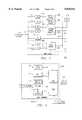
- FIG. 1is a block diagram of a centralized distribution center and satellite delivery network for use in implementing the system of the present invention.
- FIG. 2is a block diagram of a video services system embodying features of the present invention.
- FIG. 3is a detailed block diagram of several integrated receiver decoders of the video services system of FIG. 2.
- FIG. 4is a detailed block diagram of the video server and the systems control computer of the video services system of FIG. 2.
- FIG. 5is a functional block diagram of a room terminal of the video services system of FIG. 2.
- FIG. 6is a block diagram of the video services system of FIG. 2 altered to include an MPEG converter and decoder circuit boards.
- FIG. 7is a detailed block diagram of the MPEG converter of FIG. 6.
- FIG. 8is a flowchart of the operation of the MPEG converter of FIGS. 6 and 7.
- FIG. 9is a flowchart of the operation of the video server of FIG. 6.
- the reference numeral 100refers to a satellite communication system 100.
- the system 100includes an uplink facility 102 for transmitting encoded and compressed digital video programming signals stored in a distribution center 104 to a satellite 106. Once received by the satellite 106, the video data signals are relayed to equipment within a plurality of hospitality establishments, which in the illustrated embodiment are represented by hospitality systems 108, 110 and 112.
- each of the systems 108, 110 and 112has its own downlink facility 108a, 110a and 112a, respectively, it being understood that in an alternative embodiment, multiple hospitality establishments can share downlink facilities.
- the system 100may be used, for example, to transmit digitized, encoded programming from one or more central locations to satellite 106, which then re-transmits the programming to numerous remote hospitality establishments throughout the world.
- the digital programmingis encoded according to standards set by the Motion Picture Experts Group (MPEG); however, other encoding and compression standards, including proprietary standards, could also be utilized.
- MPEGMotion Picture Experts Group
- the encoded datais converted to microwave radio signals and is transmitted from the uplink facility 102 to the satellite 106.
- "real-time" video programming and other digitized datacan be transmitted simultaneously, utilizing the uplink facility 102 and satellite 106, to the plurality of hospitality systems 108, 110, 112.
- FIG. 2illustrates details of the hospitality system 108, it being understood similiar details comprise the other systems 110 and 112.
- video program data transmitted via the satellite 106is received by the downlink facility 108a (FIG. 1).
- the received video datais transmitted to a plurality of integrated receiver decoders (IRDs) 200 for determining the type of programming comprising the data, based on header information, the type of encoding scheme utilized and/or the frequency range of the received video data, and then processing and routing the data accordingly, as will be subsequently described.
- ILDsintegrated receiver decoders
- the received video datais encoded utilizing the MPEG-2 format, it is transmitted to a video server 202.
- the video datais encoded utilizing a proprietary coding scheme, it is decoded, decompressed, and converted to RF signals for transmission on a distribution network 204 of the hospitality system 108 as "real-time" video programming.
- the data being processedis non-video data, or if the data is for "barker screens" or audio/video advertisements, the data is transmitted to a systems control computer 206.
- the systems control computer 206receives data such as operating system updates, on-screen movie menus, synopses of the video-on-demand programming, and advertisements graphics. Advertisements may also be stored in the video server 202.
- the datafalls within a predetermined frequency range, it is determined to be a certain program for real-time transmission.
- Data in another predetermined frequency rangeis considered a separate program.
- Both the video server 202 and the systems control computer 206are connected to a plurality of room terminals 208, and a plurality of in-room TVs 210, by the video distribution network 204.
- the network 204is a radio frequency (RF) network, in which data is transmitted in a RF format to the room terminal 208 via the network 204.
- Dataalso could be transmitted via video distribution network 204 in a digital format.
- the network 204could be constructed using fiber optical cable.
- the video distribution network 204is configured in a trunk/branch structure.
- trunksIn smaller establishments, numerous branches of coaxial cable connect to a single trunk, while larger hospitality establishments may have a plurality of trunks, each of which may be associated with a particular floor of the establishment, each with a plurality of branches.
- the plurality of trunksallows the systems control computer 206 to allocate channel band width for multiple programming. For example, channel "72" can be allocated for the transmission of a movie "A" on the trunk associated with the second floor of a hotel, while at the same time, a movie "D" may be transmitted on channel "72," on the trunk associated with the third floor of the hotel.
- the video distribution network 204is connected to a plurality of room terminals represented by room terminals 208.
- each of the guest roomswill have one room terminal 208 per TV 210.
- the room terminal 208interfaces with the systems control computer 206, the video server 202 and other video sources (not shown) controlled by the computer 206, and an in room TV 210.
- the room terminal 208is usually a self-contained unit, but can also be a "smart tap" connected to the wall or reside within the TV 210.
- the room terminal 208can have two or more external buttons or a full keypad (not shown) for use by the customer in selecting programming and changing television channels.
- the room terminal 208may have no external keys, in which case the customer uses a remote control 212 and/or alternative channel changer arrangements (not shown) of the TV 210 to perform the aforementioned functions.
- the room terminal 208is utilized to control reception of the broadcast television and special pay-per-view and video-on-demand programming.
- the room terminal 208also controls use of interactive video services by providing a user interface to the systems control computer 206 and various system applications.
- the room terminal 208can transmit data to the systems control computer 206. Some room terminals transmit video data directly to the computer 206 immediately upon receipt thereof. Other room terminals temporarily store the data and transmit only after being polled by the computer 206.
- the TV 210 and remote control unit 212are preferably standard units. Some TVs which are currently available include the functionality of the room terminal 208, such that a separate unit is not needed. In addition, some TVs use unique protocols to communicate with the associated room terminals. Moreover, as will be shown and described with reference to FIG. 5, the room terminal 208 and/or the TV 210 may be connected to magnetic card reading devices that are capable of reading and transmitting credit and debit card information to the systems control computer 206 for validation.
- datais received by the downlink facility 108a and transmitted to the IRDs 200.
- the IRDs 200decode and decompress all "real-time" pay-per-view programming, i.e., programming to be immediately broadcast to customers at prescheduled times, and directly transmit such programming in an RF format to the video distribution network 204. It is anticipated that in a another embodiment, "real-time data" actually may be transmitted and received several times faster than real-time necessary for viewing.
- the customeruses the remote -control 212 to change the TV 210 (or the room terminal 208) to an appropriate channel to receive the pay-per-view programming. If the customer chooses the programming, the room terminal 208 notifies the systems control computer 206, and a billing record is established. Alternatively, the systems control computer 206 monitors the room terminal 208, records that the customer has chosen pay-per-view programming, and establishes a billing record.
- FIGS. 3 and 4are detailed functional block diagrams of select portions of the system 108 of FIG. 2.
- the downlink facility 108areceives encoded data signals from the satellite 106 (FIG. 1) and transmits the received data signals to individual IRD circuits 200a-200f at a bit rate of 3.3 or 6.6 megabits per second (Mbps).
- Mbpsbit rate
- the data signalswill typically have been previously multiplexed utilizing a known frequency multiplexing format.
- the datais transmitted in packets of information.
- the IRDs 200can be the type manufactured by and commercially available from Compression Lab, Inc.
- each IRD 200a-200fincludes a satellite quadrature phase shifting keying (QPSK) demodulator and a video/audio decoder (not shown).
- QPSKphase shifting keying
- Each IRD 200a-200fis programmed to decode signals within a preselected frequency range.
- the video services system 108FIG. 1 would have one IRD 200a-200f for each item of "real-time" pay-per-view programming transmitted by the satellite 106; that is, if the system commonly receives eight separate pay-per-view programs, it will have eight IRDs. Any number are contemplated.
- each IRD 200a-200fincludes a data expansion unit (DEU) 300a-300f.
- the DEUs 300a-300fare modules added to the IRDs 200 and provide ports for an RS-232 serial connection and an RS-449 connection for data transfer to the video server 202.
- the DEUs 300a-300fenable the IRDs 200 to transmit digital data directly to the systems control computer 206 via an RS-232 serial port and transmission line 302.
- the DEUs 300a-300falso enable the IRDs 200a-200f to transmit digital data directly to the video server 202 via an RS-449 port and a transmission line 304.
- Each IRD 200is connected to a frequency modulator 306a-306f, to which it outputs standard NTSC audio/video signals.
- Each frequency modulator 306a-306fconverts the NTSC audio/video signals received from the IRDs 200 to an RF format.
- the frequency modulators 306a-306fmodulate the signals to an appropriate television carrier frequency for tuning reception by the room terminal 208 or TV 210.
- the modulated signalsare then transmitted via a transmission line 308 to the video distribution network 204 (FIG. 2).
- all of the IRDs 200are connected, via the associated DEUs 300a-300f and a transmission line 310, to an intelligent RF modem (FIG. 4). As will be described, the intelligent modem monitors the IRDs 200 to determine service status and to issue channel change commands.
- the IRDs 200are capable of differentiating between data within a given packet of information. For example, when video programming is encoded, some packets contain data for an entire screen, or portion of a screen, and other packets only contain data representing changes that occur to the given screen. The second type of packet often does not contain enough data to be a complete packet. Accordingly, data for other video programs can be added to the packet. With this invention, encoded data for the video-on-demand programming, which will be stored in the video server 202 (FIG. 2), are added to packets for the "real time" pay-per-view programs. This data is separated by the IRDs 200 and transmitted, still in its encoded format, to the video server 202.
- FIG. 4illustrates details of the remainder of the circuit of FIG. 2, it being understood the lines 302, 304, 308 and 310 of the left portion of FIG. 3 continue in FIG. 4 in the right portion thereof, as shown.
- the IRDs 200(FIG. 3) are connected to the video server 202 via the transmission lines 304.
- the video server 202is primarily used to store encoded, digitized video programming for video-on-demand services.
- the video server 202comprises a plurality of video disk drives in a video disk drive array, a video disk array controller, MPEG decoder circuit boards, and two processors, including a store-and-forward processor and a server processor.
- the video disk drivesallow only read-only access by customers. The details of these components are also described in FIG. 6 and otherwise will not be described further, since they are readily understandable by those skilled in the art in light of the present disclosure.
- the store-and-forward processor of the video server 202receives the downloaded video programming data files from the IRDs 200 and the DEUs 300a-300f via transmission line 304.
- the store-and-forward processorreconstructs the video programming data files and insures file integrity. Once rebuilt, the files for the video program are forwarded to the server processor of the video server 202.
- the server processortransmits the data files to the video disk drive array.
- the store-and-forward processoralso interfaces, via selected protocols, with the systems control computer 206. When the store-and-forward processor receives a command to transmit a movie, a command is issued to the server processor.
- the server processorcommands the disk array to download data files to the MPEG decoder circuit board.
- the signalsare transmitted from the server 202 to the video distribution network 204 via a plurality of analog video links 400.
- Frequency modulators 402are utilized to modulate the signals to an appropriate television carrier frequency for tuning reception by the room terminal 208 or TV 210.
- the video server 202is capable of switching any given programming to be output on any decoder channel.
- a video distribution switch(not shown) can be added to the system 108 between the video server 202 and the frequency modulators 402. Such a switch would function as a crosspoint switch and would allow the systems control computer 206 to allocate use of the links 400.
- the video server 202under the command of the systems control computer 206, operates so that more than one customer can simultaneously view the same video program (stored in the server 202) and can even begin viewing the selected video program at different times.
- the read-only files that are stored on the video disk array (FIG. 6) of the server 202can support multiple accesses.
- the server processorBased on a customer command input using the remote control 212 (FIG. 1), for example, the server processor directs the data corresponding to the selected video program to a separate MPEG decoder circuit board (FIG. 6). The video data is decoded and transmitted to the designated room terminal 208 and TV 210 via a separate link 400.
- the video server 202is a modular configuration, with an initial module (of disk arrays) capable of storing twenty (20) to thirty (30) programs, such as movies, depending on the length of the program, that are simultaneously accessible by thirty-two (32) customers via their in-room terminals 208 and associated TVs 210. Additional modules would enable this video server 202 to store as many as 900 full length movies that are simultaneously accessible to hundreds of viewers. However, for the hospitality market, it may not be necessary for the video server 202 ever to store a library of more than fifty (50) to one hundred (100) full length video programs. Because of its architecture, the video server 202 constantly can be updated with popular programming, while less popular programming is erased. All programs are available to all room terminals 208 and TVs 210 connected to the system 108 at any time.
- an initial moduleof disk arrays
- programssuch as movies, depending on the length of the program
- the video server 202receives commands from the systems control computer 206, which instructs the server 202 regarding which programming to play, when to play the programming and which room terminals 208 are to receive the programming.
- the video server 202determines the transmission channel and channel selection back to the systems control computer 206 via an Ethernet LAN 404.
- the system 108can be configured so that only one customer or multiple customers can access a particular video-on-demand program stored in the server 202 at a given time.
- the video server 202decodes video data comprising a selected movie using MPEG standards and transmits the decoded data utilizing radio frequencies.
- the video server 202also can store the video programming data for scheduled pay-per-view programming.
- the systems control computer 206commands the video server 202 to transmit the selected program on a channel that can be accessed by all the hospitality establishment's customers.
- the systems control computer 206monitors the room terminals 208 in order to determine which customers access the programming and should be billed for the services.
- the video server 202is connected to the systems control computer 206 via the Ethernet LAN 404.
- the systems control computer 206provides logic support for the video server 202 and comprises a processor for data processing capability, hard drive storage for storing control and program algorithms, and read only memory (ROM) and random access memory (RAM) (not shown).
- the systems control computer 206is a personal computer that utilizes an Intel 486 DX processor, 33 MHz with a 210 megabyte IOE hard disk and the SCO Lite UNIX Operating System, although it should be understood that a variety of other computer configurations can be utilized.
- the systems control computer 206will include custom applications software, sound boards and multichannel graphics circuit boards (not shown).
- the computer 206is capable of generating graphics screens, as well as video and/or audio prompts, to interact with customers.
- the systems control computer 206is connected to the room terminals 208 (FIG. 2), via the video distribution network 204.
- the computer 206receives information from the room terminals 208, and utilizes the received information to provide video and other services for the customer.
- the systems control computer 206is also connected, preferably via RS-232 serial links, to the hospitality establishment's property management system (PMS) 406, a printer (not shown), a front desk terminal (not shown). These connections allow the systems control computer 206 to integrate the video services system 108 with the hospitality establishment's billing system to provide a variety of customer and billing services.
- the computer 206contains a 9600 baud modem (not shown). The modem enables remote access by the management company in order to download records and perform remote diagnosis of all system computers and allows the computer 206 to access remote data bases and services.
- the systems control computer 206is connected to the video server 202 and to graphics engines 408 via the Ethernet LAN 404.
- LAN operating softwareresides within the computer 206.
- the systems control computer 206communicates with the video server 202 according to a suitable protocol.
- the computer 206receives commands for video-on-demand programming from the room terminal 208 and send commands to the video server 202 to cause the server 202 to broadcast, or "play" the selected program.
- the computer 206monitors the video server 202 to determine which programs are available and which programs are being watched.
- the computer 206performs diagnostics and status tests on all channels in the video server 202 system.
- the video server 202can store the data for pay-per-view programming, in which case, the systems control computer 206 must include scheduling instructions and a timing means such that at prescheduled times, the systems control computer 206 can transmit a command to the video server 202 regarding which programming to play and which room terminal 208 is to receive the programming.
- the graphics engines 408are utilized to distribute selected audio, video and graphics applications from the computer 206 to remote processors.
- the graphics engines 408comprise a processor (motherboard), graphics card, Ethernet card, and audio sound card (not shown).
- a disk operating system and Windows applications for the graphics engines 408reside in the systems control computer 206.
- the graphics engines 408are utilized for generating audio/visual prompts, barker screens, and other advertisements and similar applications, which the systems control computer 206 can cause to be displayed on the TV 210 in place of broadcast advertising.
- the systems control computer 206also can be connected, via the Ethernet LAN 404, to CD ROM units (not shown).
- the systems control computer 206is connected to an intelligent RF modem 410 via an RS 232 serial link 412.
- the modem 410may be internal to the computer 206.
- the RF modem 410is utilized to convert computer communications signals to the room terminals 208 from a digital format to RF signals.
- the modem 410includes its own limited processing capability. Therefore, instead of utilizing the processing capability of the computer 206 to initiate communications to the room terminals 208 or the IRDs 200, the intelligent RF modem 410 may poll, communicate, and receive data at its own initiative and connects the appropriate terminals to the computer 206 only for status changes. As described above, the RF modem 410 provides a command and status interface with the IRDs 200.
- the systems control computer 206is directly connected to the IRDs 200 via the RS 232 serial link 302.
- Data for scheduling and billing, as well as audio/video data for advertisements,can be transmitted to the hospitality establishment via the satellite 106 (FIG. 1) or through another communications network. This data can be differentiated from other video data by the IRDs 200 and transmitted directly to the systems control computer 206 via link 302. If the data for advertisements is in the MPEG format, it will be transmitted directly to the video server 202 via link 304.
- the systems control computer 206 and the graphics engines 408are connected to the video distribution network 204 by a plurality of links 400.
- Each link 400is connected to a frequency modulator 402.
- the frequency modulator 402is utilized to modulate the signals to an appropriate television carrier frequency for tuning reception by the room terminal 208 or TV 210.
- a video distribution switch(not shown) may be added to the system between the systems control computer 206/graphic engines 408 and the frequency modulators 402. As described previously, this switch would function as a crosspoint switch and would allow the systems control computer 206 to allocate the use of the channels.
- FIG. 5illustrates details of the room terminal 208.
- a customerresponds to a menu displayed on the TV 210 that lists programming stored in the video server 202 by using the remote control unit 212 to select items from the menu.
- Infrared signals generated by the remote control unit 212are transmitted to the TV 210, which transmits the signals to a data processor 500 of the room terminal 208.
- These signalsalong with the unique address of the room terminal 208, are transmitted to the systems control computer 206.
- the systems control computer 206processes the request and issues commands to the video server 202 via the Ethernet LAN 404.
- the systems control computer 206also transmits audio/video or graphic instructions to the TV 210 instructing the customer to tune the TV 210 to a specific channel frequency bandwidth, such as that represented by "channel 15," to receive the programming.
- the room terminal 208can tune the channel for the customer.
- the systems control computer 206processes billing information entered by the customer, if such billing information is entered using a card reader 502 or the remote control unit 212, or adds the charge for the service to the room bill by accessing the establishment's property management system 406 via an RS 232 serial link.
- the systems control computer 206transmits commands to the video server 202 and frequency modulators 402 designating a channel for transmitting the selected program.
- the video server 202Upon receipt of a particular command from the systems control computer 206, the video server 202 begins downloading the selected programming from the appropriate disk drives (not shown) to a buffer (not shown) within the decoder circuit boards (FIG. 6).
- the decoder circuit boards (FIG. 6)are internal to the video server 202; but they can comprise a separate unit.
- the decoder circuit boards (FIG. 6)convert the data from MPEG format to NTSC format.
- the datais converted from digital signals to RF signals. These RF signals are then transmitted from the video server 202 to the frequency modulators 402, which modulate the signals to the appropriate frequency channel.
- the system as described hereinallows customers to interact with the programs stored in the video server 202.
- customerscan use the remote control unit 212 to implement a "bookmark" application.
- This applicationallows customers to stop the transmission of a selected video program and begin watching the program from the exact same point at a later time, until the program is erased from the video server 202 by the reception of new programming via the system 100.
- time limit parameters for the "bookmark” applicationcan be programmed into the systems control computer 206; for example, bookmarks could be erased after 24 hours.
- the systems control computer 206is notified of the status change by the PMS 406. In response to the notification, the systems control computer 206 could command the video server 202 to erase that customer's bookmark.
- the room terminal 208transmits the signal for the bookmark application via the video distribution network 204 to the systems control computer 206.
- the systems control computer 206receives the command and stores the room number, billing information, channel information, and other vital information in its memory.
- the computer 206also transmits commands, via the LAN 202, to the video server 202 to cease transmission of the program and to mark in its memory the stopping place.
- the customercan reactivate transmission of the programming with the remotecontrol unit 212.
- the room terminal 208transmits the command to the systems control computer 206 via the video distribution network 204.
- the systems control computer 206receives the transmission and forwards the appropriate data to the video server 202 via the LAN 404 to reactivate transmission of the program from the location of the bookmark.
- the system 100 as described hereinis capable of receiving advertisements from the uplink facility 102 and satellite 106 (FIG. 1) and storing them either in the systems control computer 206 or the video server 202.
- the advertising datais forwarded to the appropriate storage facility by the IRDs 200 and DEUs 300a-300f based on the format of the encoded signals.
- data for time schedules for transmitting the advertisement to the room TVs 210 and channel information, as well as header information identifying the advertisementare transmitted with the advertisement.
- advertisementsare shown at scheduled times. For example, a cable news station chooses to let the hospitality establishment or system 100 service provider show its own advertisements instead of the regular broadcast advertisements.
- the systems control computer 206begins to transmit one of the advertisements over links 400.
- the transmitted advertisementis modulated to the appropriate channel by frequency modulator 402.
- the systems control computer 206transmits appropriate signals to the video server 202 via the Ethernet LAN 404, identifying the advertisement to be transmitted, the transmission channel over which it is to be transmitted, and other information.
- the advertisementis transmitted via links 400 to the frequency modulator 402 where it is modulated to the appropriate frequency.
- the customerreceives the advertisement transmitted by the systems control computer 206 rather than the one transmitted by the cable television station.
- some television and cable stationsprecede their advertisements with a transmitted queue tone.
- the systems control computer 206monitors the programming for a queue and upon detecting the tone, the appropriate advertisement is transmitted as described above.
- the systems control computer 206can selectively insert commercials based on the viewing habits of each particular customer.
- the systems control computer 206retains records of the video-on-demand services and pay-per-view programming viewed or purchased by each customer for billing and other purposes.
- the systems control computer 206utilizes this database to determine which programming the customer has already viewed.
- the systems control computer 206can delete advertisements for those programs from the commercial transmission schedule algorithm for that customer.
- an algorithmcan be used by the systems control computer 206 to select and transmit commercials based on the customer's interests.
- the systems control computer 206will determine that the customer prefers adventure programs and command that a larger proportion of advertisements transmitted to that customer are directed toward adventure programs.
- These advertisements controlled by the systems control computer 206can reside in hard disk memory of the systems control computer, in the hard disk array of the video server 202 or in a graphics engine 408.
- cable or network program codes(the identification code for each broadcast program), as well as program schedules, can be input into the systems control computer 206 via the 9600 baud modem (not shown) or the satellite or other communications network link via the IRDs 200 and DEUs 300a-300f.
- the identification code for the movie "Beauty and the Beast"is "83502.”
- the systems control computer 206monitors and polls the plurality of room terminals 208, it determines the channel that a customer is accessing with the TV 210. An algorithm compares that channel with the time of day, the schedule, and the program identification codes. The systems control computer 206 then determines and records in an internal data base the programming viewed by the customer as determined by the customer's room terminal 208.
- the systems control computer 206can use the internal data base information to determine what type of programming the customer prefers and then transmit advertisements for similar programming to the customer. For example, if the customer views the movie "Beauty and the Beast" on a cable television channel, the computer 206 commands that a larger proportion of advertisements for the children's programming stored in the video server 202 is transmitted to the room terminal 208 and displayed on the TV 210.
- the room terminal 208is equipped with with the optional card reader 502. It should be understood that various functions and circuits of the room terminal 208 not directly related to the invention as disclosed herein are not shown or described herein. As previously indicated, many TVs now have internal data processors and infrared receivers and incorporate much of the same capability as room terminals manufactured as recently as five years ago. Because of the increased capability of the TV 210 and duplicated functionality, it has become common in the art for a video services system to utilize room terminals with decreased functionality, but including a data processor, such as the data processor 500, that is capable of interacting, via protocols, with the processor of a TV 210.
- a data processorsuch as the data processor 500
- Data processor 500is connected to a processor (not shown) of the TV 210 via an RJ 11-type interface (not shown).
- RJ 11-type interface(not shown).
- the room terminal 208includes a power supply 504, which outputs +5 volts for use by the circuits of the room terminal 208. Because of the low power requirements of the room terminal 208, it can receive power from a wall plug or from the TV 210.
- a transmitter 506is utilized by the room terminal to transmit signals to the systems control computer 206. When the transmitter 506 receives data and the appropriate signal from a data processor 500, the resulting signal is output to the systems control computer 206 by means of a diplexer 508.
- the diplexer 508provides capability both to transmit and receive signals over the RF carrier network 204. Cable or broadcast television signals pass through the diplexer 508 directly to the TV 210. Commands or other signals from the systems control computer 206 are directed by the diplexer 508 to a frequency shift key (FSK) receiver 510 and then to the data processor 500.
- FSKfrequency shift key
- the data processor 500receives inputs from and controls almost all circuits comprising the room terminal 208.
- Each room terminal 208 in the hospitality establishmenthas a unique identification number, or address, that is stored in the processor 500.
- the processor 500must at least have adequate processing capability to process billing data received from the optional card reader 502 and commands received from the TV 210, including commands input by the customer with the remote control unit 212. Characteristically, this data is temporarily stored in a nonvolatile random access memory (RAM) 512. Data is read from the RAM 512 and transmitted to the transmitter 506 when requested by the systems control computer 206 (i.e., when the room terminal 208 is polled by the computer 206). Alternatively, the data is read from the RAM 512 and transmitted by the transmitter 506 without being polled by the computer 206 if the communications are initiated by the room terminal 208.
- RAMnonvolatile random access memory
- the data processor 500interacts with the TV's data processor (not shown).
- the data processor 500 and the systems control computer 206manipulate the tuning of the TV 210 tuning for reception of video-on-demand programs and to prevent unauthorized access to programming.
- the systems control computer 206transmits instructions to customers using audio/video or graphics screens, instructing them to tune to a particular channel frequency bandwidth to view the selected video-on-demand programming.
- hospitality video systemsreserve a block of channel frequency bandwidth that cannot be tuned by the customer for video-on-demand programs.
- a customeruses the remote control unit 212 to select programming from a menu displayed on the TV 210.
- the room terminal 208Upon receipt of signals from the remote control unit 212, via the TV 210, the room terminal 208 transmits commands to the systems control computer 206 requesting broadcast of the selected video-on-demand program.
- the systems control computer 206transmits appropriate commands to the video server 202, including channel frequency bandwidth information.
- the systems control computer 206transmits the commands to the room terminal 208 and the TV 210 instructing that the channel is tuned to the same channel frequency as that being transmitted by the video server 202.
- the channel frequency actually usedis different than the one selected by the customer.
- the systems control computer 206 and room terminal 208cause the selected program to be received at a channel frequency bandwidth different than that selected by the customer.
- the systems control computer 206 and the room terminal 208will retune the TV 210 to a frequency bandwidth normally inaccessible by the customer (e.g., channel "28") unless a movie or other video-on-demand program is ordered.
- the customeris unaware of this activity.
- Other customers that tune to channel "15"will not receive the video-on-demand programming selected by the particular customer. In this manner, and because the process is controlled by the systems control computer 206 and the room terminal 208, unauthorized access to video-on-demand is blocked.
- FIG.6is a functional block diagram of an alternative hospitality system 600 similar in some respects to the system 108.
- the system 600includes an MPEG converter 602.
- the MPEG converter 602provides an advancement to the architecture of system 108, as described below.
- the MPEG converter 602enables the system 600 to multiplex data transmitted from the computer 206 and data transmitted from the video server 202 onto a single transmission channel for transmission to the TVs 210.
- the decoder (FIG. 6) buffer 607 for a given frequency channelis receiving data from two sources, the data are multiplexed onto that given transmission channel.
- the converter 602enables screen data from the computer 206 and the server 202 to be merged in a manner that a new screen is formed and transmitted to the TVs 210.
- the systems control computer 206executes the same functionality described above with respect to FIG. 4.
- the computer 206is utilized to generate graphics screens and animation, as well as short audio/video programs that have been digitized and stored on a hard disk or in CD ROM format.
- the computer 206can utilize graphics engines 408 (FIG. 4) to generate audio, video, and graphics data.
- graphics engines 408FIG. 4
- the ever increasing processing capability of the personal computers utilized to perform the functionality for the systems control computer 206may reduce the need to use separate graphics engines 408 for generating graphics data.
- the systems control computer 206is connected to an RF modem 410.
- the MPEG converter 602is installed in a video graphics array (VGA) port of the systems control computer 206.
- VGAvideo graphics array
- the MPEG converter 602receives the graphics data via the computer's internal bus 604.
- the design of the converter 602enables it to function in conjunction with a multiplicity of computer operating systems, including UNIX OS2, and Windows NT.
- the MPEG converter 602can have MPEG-1 and/or MPEG-2 encoding capability.
- MPEGMotion Picture Experts Group
- MPEG bitstreamconsists of header data and some number of groups of encoded frames.
- the primary layer of the header informationis utilized to define the extent of all the video data that is encoded in the subsequently transmitted data frames. This top most header organizes the data frames into what is known in the art as a "group of pictures," and informs decoder boards 606 of the pixel locations that will be affected by the encapsulated data frames.
- a group of picturesmay be defined to encompass the entire graphics screen presented on the TV 210 and consists of several MPEG screen types (e.g., I, P, and B).
- a subsequent group of pictures of the same screen typesmay be defined that utilize on the upper quadrant of the screen.
- MPEG codingconsists of four types of data frames (also referred to as "pictures"): I-frames which are coded without reference to other frames; P-frames which are predictive frames encoded using motion compensation from the previous I-frame; B-frames which are bidirectionally predictive using motion compensation from previous or future I, P or D-frames; and D-frames which are used only for fast-forward functionality.
- I-frameswhich are coded without reference to other frames
- P-frameswhich are predictive frames encoded using motion compensation from the previous I-frame
- B-frameswhich are bidirectionally predictive using motion compensation from previous or future I, P or D-frames
- D-frameswhich are used only for fast-forward functionality.
- the MPEG converter 602utilizes MPEG-1 or MPEG-2 capability for the purposes of transmitting computer generated graphic screens for advertising video-on-demand programming and for services such as "video checkout" on the TV 210.
- the MPEG converter 602receives 32 channels of graphics screen data with a resolution of 320 lines by 200 columns and 256 colors from a palette of 224 possible colors. After the encoding process is completed, the MPEG converter 602 outputs to the video server 202 MPEG-1 digital signals, in which the "I-frame" is encoded, over a 16 bit synchronous transmission line 608.
- an advanced-functionality MPEG converter 602 with MPEG-2 capabilityreceives both graphical and digital data input from the systems control computer 206. Typically, it receives thirty-two (32) channels of graphics data, with a resolution of 640 lines by 400 columns and 24 bit true color capability. In addition, this embodiment of the MPEG converter 602 receives from the systems control computer 206 thirty-two (32) channel digital data input, including MPEG-2 encoded I- and P-frame data. Characteristically, the MPEG converter 602 receives digital data via 16-bit or 32-bit synchronous transmission line 604.
- the MPEG converter 602When receiving data that already is encoded in MPEG-2 format, the MPEG converter 602 functions as a digital multiplexer and is capable of superimposing, or overlaying, the data with video programming that is stored in a disk array 610.
- the MPEG converter 602has sufficient resident memory (FIG. 7), specifically, 2 to 64 megabytes of RAM, to save thirty-two (32) screens.
- the digital signal processor (FIG. 7) for the MPEG converter 602is, for example, a Texas Instruments TMS 320C40 or TMS 320C44 and has the capability to encode up to thirty two channels of graphics data per second.
- the MPEG converter 602has a bitmap hardware register (FIG. 7) that identifies and tracks the channels that have been modified, by an X-Windows driver (not shown) of the systems control computer 206, to contain graphics or video data.
- the X-Windows driveris a Unix-based windowing system that provides a program interface for graphic window displays. After the MPEG converter 602 encodes a given channel, the bit register is cleared.
- the MPEG converter 602can be a stand-alone unit located between the systems control computer 206 and the video server 202.
- the MPEG converter 602receives graphics data via the transmission line 604.
- the transmission line 604could be one of a variety of arrangements sufficient in bandwidth capability to receive graphic primitives from the systems control computer 206.
- the transmission line 604is the Industry Standard Architecture (ISA) bus internal to the systems control computer 206.
- the MPEG converter 602is connected to the video server 202 via the transmission line 608.
- the transmission line 608is a synchronous SCSI-2 bus interface connectable onto the internal SCSI-2 bus of the video server 202. If located more that ten (10) feet from the video server 202, the MPEG converter 602 preferably would be connected via fiber optic cable.
- the MPEG converter 602can be hardware installed within the video server 202.
- the MPEG converter 602would be connected to an internal bus 612 of the video server 202 and still would be connected to the internal ISA bus (not shown) of the systems control computer 206 that is extended to the MPEG converter 602 via transmission line 604.
- this embodimentcould be advantageous when a video server 202 is being accessed off-premises from a centralized location for numerous hospitality establishments or for a non-hospitality application (e.g., residential customers) and is receiving data from one or more computers 206.
- the computers 206could reside in locations remote from the video server 202 and each computer 206 could be operated by different service providers.
- This implementationwould be especially advantageous in an architecture where the video server 202 is part of a common carrier's video dial tone network.
- Various service providerseach with a computer 206, could have tariffed access to the network to broadcast advertising and service offerings with graphic screens and audio/video.
- This datawould be received, encoded, and multiplexed onto the common carrier's network by the MPEG converter 602 in the same manner as described herein.
- MPEG converter 602 functionalitycould be incorporated into the operations software of the systems control computer 206.
- the X-Windows driver for the systems control computer 206would be modified to write image data to memory buffers allocated from the computer's RAM.
- An "encode and send" primitiveis used which commands the driver to perform an MPEG I-frame encode on the selected screens in the memory buffer, and write the encoded buffer to a standard transmission interface (e.g., SCSI-2).
- the systems control computer 206also requires a special device driver and an SCSI controller. In order to execute this functionality, the systems control computer 206 requires a 66-100 MHz Pentium processor (Intel 80586 microprocessor) and additional 128 megabytes of RAM memory.
- Graphics engines 408(FIG. 4) also can be modified to utilize the MPEG converter 602.
- a graphics engine 408When a graphics engine 408 is selected by the systems control computer 206 to generate a graphics screen, the engine 408 arbitrates for local bus access to the computer 206 and writes data to the assigned channel on the MPEG converter 602 using as serial telecommunications bus (STB) standard channel driver (not shown).
- STBserial telecommunications bus
- the MPEG converter 602 and the disk array 610are connected via internal bus 612 to the MPEG decoder boards 606.
- internal bus 612is a SCSI-2 bus.
- the SCSI bus 612is particularly suited to this architecture both because its data transmission capacity of ten (10) megabytes per second allows for rapid transmission of the data screens and its transmission capability can be driven by multiple master devices.
- both the systems control computer 206 and the video server's processor unit(not shown) function as a master driver for the SCSI bus 612 by controlling the transmission of data from the MPEG converter 602 and the disk array 610 to the decoder boards 606.
- the functions of both the disk array 610 and the MPEG decoder boards 606are described with reference to but not shown in FIG. 4.
- Screen data encoded by the MPEG converter 602is transmitted, stored, and displayed from screen buffers 607 internal to the decoder boards 606.
- the buffers 607contain enough memory to build several screens of 352 ⁇ 240 resolution.
- the MPEG data received into the buffers 607is decoded from MPEG format and then encoded into NTSC, PAL, or SECAM formats. Once all the screen information is present in the particular buffer 607 and is encoded, the information is transmitted to connected TVs for viewing. Because the buffer 607 for a given frequency channel is receiving data from two sources, the data are multiplexed onto that channel for transmission via the network 204 to the TVs 210. The screen continues to be displayed until it is overwritten completely or partially by new data transmitted to the same decoder board 606.
- Any portion of a screen generated by the systems control computer 206will continue to be displayed from the decoder board's screen buffer 607 if the subsequent MPEG data displayed on the same channel contained in the group of pictures defined to encompass less than an entire screen. In this manner, full motion video and sound can be overlaid over computer generated graphics.
- Transmission line 400 and frequency modulator 402are described in FIG. 4
- a computer generated graphic screen used to advertise a video program(e.g., the movie Jurassic Park).
- the graphic screen datais stored on the hard disk of the systems control computer 206.
- the data for the screenis mapped onto the internal RAM memory of the MPEG converter 602 and encoded by its processor, as described in FIG. 7.
- the header and screen informationare copied to an MPEG decoder board 606, via SCSI bus 608 and 612.
- the header dataprovides the decoder board 606 with information concerning the organization of the data frames being transmitted and the location of the encoded pixels. Important to this example, the header information also informs the decoder board 606 that the data frame is not a complete screen and will only encompass a given quadrant of the screen.
- the encoded data for the screenis captured by the decoder's buffer 607.
- the decoder board 606then decodes the data into RF signals and transmits it to a frequency modulator 402 via link 400.
- the data from the encoded screenremains in the decoder's internal buffer 607 until it is overwritten all or in part by data from a subsequent transfer.
- the graphic screen transmitted from the MPEG converter 602contains only text and thus is not a complete screen.
- the graphic screenis transmitted on the same channel and to the same decoder 606 that previously is being utilized by the video server to display a short audio/video section, of a given movie (Jurassic Park), that is stored on the disk array 610.
- the data from the disk array 610 transmissionremains in the decoder buffer 607, with only a portion of it replaced when the decoder 606 receives the graphic information from the MPEG converter 602.
- the decoder buffer 607then transmits the superimposed image to the room terminal 208 and TV 210.
- the MPEG converter 602is capable of providing subtitles for the entertainment programming stored in the disk array 610.
- Special menu screensare provided for customers offering the optional use of subtitles. For example, customers can be given the choices such as, "Press 1 for subtitles; Press 0 to view the movie now.” If the customers press the "1" key on the remote control 212 (FIG. 2) keypad or the room terminal 208 keypad, they receive additional choices such as, "Press 1 for French, Press 2 for Spanish, Press 3 for English.”
- the customers' responsesare transmitted upstream to the systems control computer 206. Once the response is received, the computer 206 activates the appropriate file containing the data for the subtitles as well as timing and synchronization algorithms.
- the graphics data for the subtitlesis then processed and superimposed over the audio/video programming (e.g., Jurassic Park) being copied from the disk array 610 to the decoders 606 using the process as described above and in FIG. 7.
- FIG. 7is a functional block diagram showing details of the MPEG converter 602.
- the MPEG converter 602is internal to the systems control computer 206 and is connected to that computer via an Industry Standard Architecture (ISA) bus 701.
- ISAIndustry Standard Architecture
- the ISA bus 701is a commonly used bus architecture on the motherboard of computers with MS-DOS and UNIX disk operating systems.
- the ISA bus 701can support 8- and 16-bit data transfers.
- the MPEG converter 602can be adapted to function with a 32-bit bus such as the Extended Industry Standard Architecture (EISA) bus.
- EISAExtended Industry Standard Architecture
- the MPEG converter 602can reside exterior to the computer 206.
- the systems control computer 206writes graphics data for a given graphics screen to a shared global dynamic RAM 702 via the ISA bus 701. Data is written to the dynamic RAM 702 in a manner emulating data written by a computer to a VGA display adapter.
- the MPEG converter 602is able to emulate most existing VGA display adapters currently available in the marketplace by receiving and processing data formatted for those VGA circuit boards.
- the dynamic RAM 702 of the MPEG converter 602contains two to four megabytes of memory and contains a bank of as many as thirty-two windows for receiving and storing graphics screen data. The foregong are represented in FIG. 7 as bank selectable windows 703a-703n.
- the unique window configurationallows the computer 206 to plot simultaneously multiple graphics screens in the RAM 702 memory, each to be transmitted on a specific channel.
- the window configurationalso allows the MPEG converter 602 to multiplex screens onto a given transmission channel with the video screens from the video server 202.
- the RAM 702can fulfill functions similar to a digital switch with the graphic being transmitted over the channel to the appropriate TV 210.
- Each window 703a-nis a contiguous block of 64 or 128 kilobytes of data.
- the RAM 702can be expanded to 64 megabytes total of memory, enabling bank selectable windows 703a-n with increased memory capability and/or an increased number of windows.
- the RAM 702can receive data either at eight (8) or sixteen (16) or thirty-two (32) bit wide data quantities.
- the MPEG converter 602also contains a digital signal processor 704.
- the processor 704is utilized to execute the algorithms and computations necessary to simultaneously encode multiple channels of video graphic data into MPEG-1 or MPEG-2 images.
- the preferred processor to execute this functionality of the processor 704is a Texas Instruments TMS320C44. Other processors could be used. However, to execute the required functionality, the processor should have the capability of executing approximately ten times as many instructions per second as an INTEL 486; 33 MHz processor.
- the digital signal processor 704 and the shared global dynamic ram 702are connected via a shared global bus 705.
- the digital signal processor 704utilizes local RAM memory 706 to provide fast access memory to store working program data.
- the local RAM 706provides 512 kilobytes of 0-wait state static RAM.
- the digital signal processor 704is connected to the local RAM 706 via local bus 707.
- the digital signal processor 704is utilized to encode graphics data, or other data generated by the systems control computer 206, into MPEG-1 or MPEG-2 standard encoded data.
- the digital signal processor 704normally will encode the signals into the MPEG-1 format and will only be encoding I-frames.
- B- and P-framesare "predictive" frames that represent changes to the I-frames. With static graphic screens, B and P frames usually are unnecessary.
- the MPEG converter 602will encode I-, B-, and P-frames utilizing the MPEG-2 format.
- the graphic imagefirst will undergo a color-space conversion to a coded frame broken into luminance (Y) and two chrominance components (Cb and Cr). Because natural images are not noticeably affected when the chroma components of the image are reduced, both the Cb and the Cr chrominance components are reduced by a factor of two.
- the luminance and the chrominance elementsare grouped into macro-blocks of 8 ⁇ 8 pixels.
- a spacial frequency transform(referred to in the art as a discrete cosine transform or DCT) is applied to the macro-blocks to obtain better organization of the data.
- the high frequency components of the transformare discarded.
- the resulting horizontal and vertical spacial frequency coefficientsare mapped in a fashion known in the art as a "zig-zag" scan, by ordering AC (non-zero) coefficients from the lowest spacial frequency to the highest. Coefficients of the vector are then uniformly scalar quantized, run length coded, and finally, the run-length symbols are variable length coded using a "modified-Hoffman" scheme. Global redundancy is reduced, followed by quantization and variable length entropy coding of the data.
- the digital signal processor 704is capable of utilizing a variety of error correcting techniques, known in the art, in order to correct sampling errors and limit image degradation during the conversion process.
- the MPEG converter 602is required to encode graphics screens made up of 320 columns by 200 lines by 256 colors.
- the digital signal processor 704simulates the extended register handshake of an appropriate graphics adapter in order to map in different parts of a complete screen.
- the digital signal processor 704sets an internal timer (not shown) whose maturation will schedule an MPEG conversion of the targeted screen.
- An "interrupt" signal resulting from systems control computer's 13 requesting a different screenwill force the maturation of the timer and results in the immediate scheduling of the previously selected screen for MPEG conversion.
- Miscellaneous input/output (I/O) registers 708are a bank of special function hardware registers that control the operation of the MPEG converter 602.
- the miscellaneous I/O registers 708are used for general purpose read-write functions; ISA bus 701 and digital signal processor 704 read-write functions and digital signal processor 704 interrupt functions.
- the miscellaneous I/O registers 708execute these functions via connections to the ISA bus 701 and to the dynamic RAM 702 and digital signal processor 704 via lines 709a and 709b.
- miscellaneous I/O registers 708are utilized to set the address default range for the MPEG converter's ISA bus 701 monitoring capability. When the addresses for a read or write on the ISA bus 701 fall within the default range, the I/O control registers 708 trigger the operation of the I/O capture register 710.
- the default values utilized by the registers 708are the standard VGA I/O addresses.
- the miscellaneous I/O control registers 708are programmable and can encompass enlarged, or different, default ranges. Accordingly, the I/O control registers can be programmed to allow the MPEG converter 602 to emulate most VGA circuit boards currently available in the marketplace. Default values are loaded into the miscellaneous I/O control registers 708 at system initialization.
- An I/O capture register 710is composed of a group of hardware latches and is utilized to seize the contents and source of the address data. Likewise, the I/O capture registers 710 capture the contents of the data bus (ISA Bus 701) data during the ISA bus 701 1/0 operations that meet the selection criteria as defined by the miscellaneous I/O control registers 708. For example, during an I/O "write" cycle, the address transmitted on the ISA bus 701 is compared with the parameters stored in the miscellaneous I/O control registers 708. If the address falls within the range, 16 bits of the address and 16 bits of the data content are stored in a buffer 607 internal to the I/O capture register 710.
- An "interrupt” signalthen is issued to the digital signal processor 704 and a "ready” signal (also known in the art as a "CHRDY line") is asserted on the ISA bus 701.
- the "ready” signalremains asserted until the digital signal processor 704 reads the content of the data present in the I/O capture register 710 buffers.
- the I/O capture register 710 buffer(not shown) is a single 32 bit buffer on the shared global bus 705. The process is similar for the "read” function.
- the digital signal processor 704After the "ready” signal is recognized, the digital signal processor 704 performs a data "write” into the internal buffers of the I/O capture register 710.
- the miscellaneous I/O control registers 708 and the I/O capture register 710provide this architecture with flexible functionality and unique capabilities.
- the MPEG converter 602is capable of emulating the hardware registers and handshake protocols of most VGA registers and handshake protocols of most VGA circuit boards currently manufactured.
- the registers 708 and 710allow the MPEG converter 601 to process the multiple screens mapped into the windows 703 of the RAM 702. Since operation of the I/O capture register 710 is driven by software resident in the digital signal processor 704, the MPEG converter 602 also has expanded capability to perform numerous unique applications, including others described herein.
- the I/O capture registeralso provides flexibility for future growth and eliminates the risk of not having the capability to emulate the correct parameters and protocols of any given VGA vendor.
- the MPEG converterhas two data output interfaces, which are the SCSI interface 711 and the first-in first-out (FIFO) buffer 712.
- the SCSI interface 711is an interface to the SCSI bus 602 (FIG. 6) described above. It provides synchronous data transfer capability at 8-bit SCSI and 16-bit SCSI standards.
- the digital signal processor 704transmits the MPEG data streams to the video server 202 by means of issuing an SCSI "COPY" command.
- the FIFO buffer 712outputs data via the ISA bus 701.
- the FIFO buffer 712receives sequential data from the digital signal processor 704 and re-transmits the data in the exact order.
- the FIFO buffercan be used to transmit data to a transmission interface that is also connected to the ISA bus 701, such as a LAN interface.
- the FIFO buffer 712is utilized to output diagnostic or record-keeping data.
- the FIFO buffer 712can output encoded video data to a SCSI interface residing on the ISA bus 701 (not shown).
- the systems control computer 206In operation of the MPEG decoder 602, the systems control computer 206 generates a graphics screen for transmission to room terminal 208 and TV 210 (FIG. 2). The data for the screen previously has been saved on the hard disk of the systems control computer 206. As the graphic screen is generated, it is mapped via the ISA bus 701 onto a bank selectable window 703a-n of the shared global dynamic RAM 702 pertaining to a specific VGA channel. The computer 206 first writes a picture element (PEL) to the bank selectable window 703a-n at a specific address (e.g., 0x03C8 by 0x0000).
- PELpicture element
- the addressis captured by the I/O capture register 710 and stored in its buffer (not shown).
- An "interrupt” signalis issued to the digital signal processor 704 and a ready signal, ("CHRDY line") is issued to the ISA bus 701 halting the operation of the bus.
- the digital signal processor 704responds by identifying the bank 703a-n on which the PEL is being written, and then it reads the address captured in the I/O capture register 710 buffer.
- the digital signal processor 704resets the selected channel back to "0" and the ISA bus 701 again becomes operational.
- the systems control computer 206writes PEL data containing "red-green-blue" (R-G-B) values onto the bank selectable window 703 (e.g., at address 0x3c9) which are similarly captured by the I/O capture register 710 and read by the digital signal processor 704.
- R-G-Bred-green-blue
- the data for the screenare transferred via the shared global bus 705 to the digital signal processor 704 and encoded in MPEG format as described above.
- the screenis copied to the SCSI interface 711 and then is transmitted to the MPEG decoder boards 606 (FIG. 6). As described in FIG. 6, the screen is then decoded into RF format and transmitted to the TV 210.
- the operation of the converter 602enables the system 100 to provide several commercially desirable functions not currently available in the marketplace.
- the converter 602operates effectively as a digital switch for assigning selected graphics or screens to selected user channels.
- Current boardstypically can only provide one graphic or screen to one channel.
- a graphic advertising family entertainmentcan be generated for a specific user's channel whereas a different graphic advertising adventure entertainment simultaneously can be generated for a different user's channel.
- the arrangement describedcould be used to furnish subtitles for merge or overlay onto the presentation of a movie being played from the disk array.
- advertisement graphicscan be merged or overlaid on segments of video programming of selected channels.
- Intelligent programing of the systems control computer 206can determine the timing, content and selection of channels for providing the overlay or merger of the graphics/screens with the other source programming.
- the I/O control registers 708 of the converter 602are programmable to monitor the ISA bus 701 for a variety of different VGA signal formats and parameters. Accordingly, a separate board does not need to be built for each type of computer or graphics programs, because the converter 602 can emulate all of the various VGA formats.
- FIG. 8is a flowchart illustrating the operation of the converter 602. It is understood the functions described are implemented by instructions or logic executed by the processor 704 alone or in conjunction with other components of the converter.
- step 800graphics data is written from the systems control computer 206 to one of the bank selectable windows 703a-n.
- the data for one PELis so written (mapped) to an address in the window 703a.
- the processis again performed to write (or map) the color information (R-G-B values) for the PEL.
- the data in the computer 206is from the computer's hard disk and can comprise, for example, graphics or screens such as advertisements, movie subtitles or the like, for display on a selected user channel corresponding to a TV 210.
- step 804the control registers 708 detect the presence of the graphics data on the ISA bus 701 that was written to the bank selectable window 703a-n. Upon detection, in step 806 the control registers 708 activate the I/O capture registers 710 . In step 808 the I/O capture registers 710 reads and stores the address of the PEL written to the window 703a-n. In step 810, the processor 704 issues an interrupt command that suspends access of data to the ISA bus 701. In step 812, the processor 704 reads the address of the PEL stored in the register 710. In step 814, a determination is made whether the address of the data indicates it is the first PEL of a new screen. If yes, in step 816 a timer is set.
- the timeris used to determine when the mapping of the graphic in the window 703a-n is completed. Execution then proceeds to step 818. In step 818, a reset channel command is issued to activate the us for access of data thereto. In step 820 a determination is made if the timer is expired. If not, execution returns to step 802, wherein the color value for the PEL is written to the window 703a-n. The process then continues until the timer expires, indicating that all PEL data (graphics and color value) for the particular graphic or screen has been written to the window 703a-n.
- step 820if in step 820, the timer has expired, execution proceeds to step 822.
- step 822the completed graphic or screen stored in the window 703a-n is transmitted from the window via the shared global bus to the processor 704 for encoding.
- the screenis encoded to MPEG format in step 824.
- step 826the encoded screen is transmitted to one of two interfaces for output to the video server 202 (FIG. 6).
- One interfaceis the SCSI interface 711, which is used when the MPEG converter 602 is directly connected to the internal bus of the video server 202 via a SCSI-II line.
- the FIFO interfaceis used when the converter 602 is connected to the video server 202 via a LAN, fiber optic system or other remote transmission arrangement.
- the screenis transmitted to the server 202, it is then multiplexed or merged with other video programming or data from the disk array 610, as described below with reference to FIG. 9.
- FIG. 9a flowchart is depicted of the process for overlaying screens with video programming as performed by the video server 202.
- step 902encoded data from the processor 704 is received in the appropriate one of the decoder boards.
- Each decoder board 606decodes MPEG-encoded screens for transmission on a specific transmission channel. Specifically, the data is configured in the buffer memory (not shown).
- step 904a determination is made whether the encoded data utilizes the entire buffer 607 of the board 606. When utilizing the entire buffer 607, it is contemplated that the encoded data comprising the screen is intended to be the entire screen of for display on the TV 210.
- the individual decoder 606can receive screens from a single source, either from the systems control computer 606 or the disk array 610, or from both sources.
- the decoder 606When receiving screens from both sources, the decoder 606 functions as a multiplexer, multiplexing both screens onto the same transmission channel. When the entire buffer 607 is not utilized, it is contemplated the encoded data is then to be overlayed onto video programming from the array 610, the data from the video programming (comprising an MPEG screen) thus occupying the remainder of the buffer 607.
- step 906if the entire buffer 607 of the board 606 is utilized, then the incoming data comprising an MPEG encoded screen (either from the array 610 or the converter 602) replaces in the buffer 607 the previously buffered screen. Execution then proceeds to step 908.
- step 908the completed buffered screen is decoded from MPEG to RF format.
- step 910the decoded screen is transmitted to the TV 210.
- step 904If in step 904 the entire buffer 607 of the board 606 is not utilized, then execution proceeds to step 912.
- the screendoes not utilize (i.e., occupy) the entire buffer 607 of the board 606, this means the screen is one that is to be overlayed or merged with a screen from the disk array 610.
- step 912the encoded data from the converter 602 is buffered in the board so that it replaces only the corresponding data of the previously buffered screen of the disk array 610, thereby producing a merged screen.
- step 908wherein the completed, merged screen is decoded from MPEG to RF format.
- step 904it is understood that the merging of screen data in the buffer 607 of the board 606 does not necessarily have to be the merger of a screen from the converter 602 with a screen from the array 610.
- the principal involvedcan be used to merge two or more different screens from the converter 602. It can also be used to merge screens from sources other than the array 610 with the screens of the converter 602.
- the foregoing inventionoffers numerous commercially advantageous possibilities for combining video data content from different sources. It is contemplated that a user of the system 100 would be able, for example, to watch on a TV 210 a movie or other video program from one source, while simultaneously watching another program (or frozen screens thereof) in a portion or window simultaneously appearing on the TV 210.
- the content from the separate sourcesmight include video programming or movies, television broadcasts, hospitality or paid advertising, computer generated animation, games, instructional information and and the like.
- the system of the inventioncan be used in non-hospitality environments and can be used in conjunction with a public switched telephone network for the provision of programming and multiplexing or merging of programming with other data.
- Application of the present systemis contemplated for use with video dialtone or cable television networks.
- Transmission means other than satellite deliverymay be used.
- Encoded datamay be transmitted by any means available, for example, the data may be transmitted by microwave means or over fiber optic transmission means.
- the encoded datamay be transmitted over public and/or private telecommunications networks. Components of the system may be situated in remote locations and linked by various network configurations.
- the MPEG decoder boardscould be separate units or located as part of a room terminal or TV.
- the components of the systemmay be alternatively configured so that they are integrated into single devices or separate devices.
- Componentsmay comprise integrated circuitry or any combination of discrete or analog circuitry interconnected in a standard manner. Many of the functions may be alternatively implemented in software or hardware logic.
Landscapes
- Engineering & Computer Science (AREA)
- Multimedia (AREA)
- Signal Processing (AREA)
- Two-Way Televisions, Distribution Of Moving Picture Or The Like (AREA)
- Television Signal Processing For Recording (AREA)
Abstract
Description
Claims (19)
Priority Applications (1)
| Application Number | Priority Date | Filing Date | Title |
|---|---|---|---|
| US08/835,136US5818512A (en) | 1995-01-26 | 1997-04-04 | Video distribution system |
Applications Claiming Priority (2)
| Application Number | Priority Date | Filing Date | Title |
|---|---|---|---|
| US08/378,616US5729279A (en) | 1995-01-26 | 1995-01-26 | Video distribution system |
| US08/835,136US5818512A (en) | 1995-01-26 | 1997-04-04 | Video distribution system |
Related Parent Applications (1)
| Application Number | Title | Priority Date | Filing Date |
|---|---|---|---|
| US08/378,616ContinuationUS5729279A (en) | 1995-01-26 | 1995-01-26 | Video distribution system |
Publications (1)
| Publication Number | Publication Date |
|---|---|
| US5818512Atrue US5818512A (en) | 1998-10-06 |
Family
ID=23493845
Family Applications (3)
| Application Number | Title | Priority Date | Filing Date |
|---|---|---|---|
| US08/378,616Expired - Fee RelatedUS5729279A (en) | 1995-01-26 | 1995-01-26 | Video distribution system |
| US08/401,071Expired - Fee RelatedUS5767894A (en) | 1995-01-26 | 1995-03-08 | Video distribution system |
| US08/835,136Expired - LifetimeUS5818512A (en) | 1995-01-26 | 1997-04-04 | Video distribution system |
Family Applications Before (2)
| Application Number | Title | Priority Date | Filing Date |
|---|---|---|---|
| US08/378,616Expired - Fee RelatedUS5729279A (en) | 1995-01-26 | 1995-01-26 | Video distribution system |
| US08/401,071Expired - Fee RelatedUS5767894A (en) | 1995-01-26 | 1995-03-08 | Video distribution system |
Country Status (1)
| Country | Link |
|---|---|
| US (3) | US5729279A (en) |
Cited By (277)
| Publication number | Priority date | Publication date | Assignee | Title |
|---|---|---|---|---|
| WO1999038266A1 (en)* | 1998-01-22 | 1999-07-29 | Safi Qureshey | Intelligent radio |
| US5949411A (en)* | 1996-02-16 | 1999-09-07 | Cyber Marketing, Inc. | Remote interactive multimedia preview and data collection kiosk system |
| US6012091A (en)* | 1997-06-30 | 2000-01-04 | At&T Corporation | Video telecommunications server and method of providing video fast forward and reverse |
| US6014439A (en)* | 1997-04-08 | 2000-01-11 | Walker Asset Management Limited Partnership | Method and apparatus for entertaining callers in a queue |
| US6018765A (en)* | 1996-01-23 | 2000-01-25 | Storage Concepts, Inc. | Multi-channel multimedia data server |
| US6055560A (en)* | 1996-11-08 | 2000-04-25 | International Business Machines Corporation | System and method to provide interactivity for a networked video server |
| US6112226A (en)* | 1995-07-14 | 2000-08-29 | Oracle Corporation | Method and apparatus for concurrently encoding and tagging digital information for allowing non-sequential access during playback |
| US6119154A (en)* | 1995-07-14 | 2000-09-12 | Oracle Corporation | Method and apparatus for non-sequential access to an in-progress video feed |
| US6138147A (en)* | 1995-07-14 | 2000-10-24 | Oracle Corporation | Method and apparatus for implementing seamless playback of continuous media feeds |
| WO2000070477A1 (en)* | 1999-05-14 | 2000-11-23 | Funyellow, Inc. | System and method for generating interactive animated information and advertisements |
| US6256045B1 (en)* | 1997-02-22 | 2001-07-03 | Lg Electronics Inc. | Device and method for processing picture in MPEG decoder |
| WO2001067770A1 (en)* | 2000-03-03 | 2001-09-13 | Mizrahi Enterprises, Inc. | Method and system for selectively recording content relating to an audio/visual presentation |
| US20010049596A1 (en)* | 2000-05-30 | 2001-12-06 | Adam Lavine | Text to animation process |
| US20020002039A1 (en)* | 1998-06-12 | 2002-01-03 | Safi Qureshey | Network-enabled audio device |
| US6360234B2 (en)* | 1997-08-14 | 2002-03-19 | Virage, Inc. | Video cataloger system with synchronized encoders |
| US20020059637A1 (en)* | 2000-01-14 | 2002-05-16 | Rakib Selim Shlomo | Home gateway for video and data distribution from various types of headend facilities and including digital video recording functions |
| FR2816783A1 (en)* | 2000-11-10 | 2002-05-17 | Guillaume Dubost | Remote instantaneous transmission at 150 Mbytes per second of audio-visual data from a central point to an audio-visual data signal converter and display |
| US20020087400A1 (en)* | 2000-12-28 | 2002-07-04 | Denis Khoo | Method and system for providing a reward for playing content received over a data network |
| US20020110287A1 (en)* | 2000-11-13 | 2002-08-15 | Toshihisa Matsuo | Image recording system and method for controlling the image recording system |
| US6463444B1 (en) | 1997-08-14 | 2002-10-08 | Virage, Inc. | Video cataloger system with extensibility |
| US6463588B1 (en)* | 1998-10-08 | 2002-10-08 | Scientific-Atlanta, Inc. | Method and apparatus for restoring port status in a cable television tap |
| US20020165770A1 (en)* | 2001-05-04 | 2002-11-07 | Individual Network, Inc. | Method and system for providing content with an option |
| US20020188762A1 (en)* | 2001-05-04 | 2002-12-12 | Tomassetti Stephen Robert | Data structure for an entertainment and communications network |
| US20020188752A1 (en)* | 2001-05-04 | 2002-12-12 | Tomassetti Stephen Robert | Control messaging for an entertainment and communications network |
| US20030005449A1 (en)* | 2001-06-29 | 2003-01-02 | Mckenna Lee R. | System and method for content delivery to lodging entertainment systems |
| US20030023741A1 (en)* | 2001-05-04 | 2003-01-30 | Tomassetti Stephen Robert | Digital multi-room, multi-source entertainment and communications network |
| US20030041328A1 (en)* | 2000-01-19 | 2003-02-27 | Denis Khoo | Method and system for providing a customized media list |
| US20030039397A1 (en)* | 1998-03-31 | 2003-02-27 | Shinji Tsuchida | Method and apparatus for processing image and storing medium |
| WO2003026179A1 (en)* | 2001-09-18 | 2003-03-27 | Scientific-Atlanta Inc. | Mapping of bit streams into mpeg frames |
| US20030066081A1 (en)* | 2001-07-27 | 2003-04-03 | Barone Samuel T. | Command protocol for interactive TV production tools |
| US6563506B1 (en)* | 1998-12-14 | 2003-05-13 | Ati International Srl | Method and apparatus for memory bandwith allocation and control in a video graphics system |
| US6567980B1 (en) | 1997-08-14 | 2003-05-20 | Virage, Inc. | Video cataloger system with hyperlinked output |
| US6567985B1 (en)* | 1997-07-31 | 2003-05-20 | Canon Kabushiki Kaisha | Method, apparatus and medium for image communication |
| US6567131B1 (en)* | 1999-09-29 | 2003-05-20 | Matsushita Electric Industrial Co., Ltd. | Decoding apparatus and decoding method |
| US20030095208A1 (en)* | 1999-06-29 | 2003-05-22 | Laurent Chouraqui | Process for the creation of interactive audiovisual clips |
| US20030115282A1 (en)* | 2001-11-28 | 2003-06-19 | Rose Steven W. | Interactive broadband server system |
| US6593973B1 (en) | 2000-03-21 | 2003-07-15 | Gateway, Inc. | Method and apparatus for providing information in video transitions |
| US6633592B1 (en)* | 1996-05-17 | 2003-10-14 | Matsushita Electric Industrial Co., Ltd. | Data multiplexing method, method and device for reproducing multiplexed data, and recording medium containing the data multiplexed by said method |
| US20030210887A1 (en)* | 2002-05-09 | 2003-11-13 | Engle Joseph C | Content identification in a digital video recorder |
| US20030210889A1 (en)* | 2002-05-09 | 2003-11-13 | Engle Joseph C. | Detection rules for a digital video recorder |
| WO2003096686A1 (en)* | 2002-05-09 | 2003-11-20 | Thomson Licensing S.A. | Content identification in a digital video recorder |
| WO2002076100A3 (en)* | 2001-03-20 | 2003-11-27 | Thomson Licensing Sa | Method and system for remote diagnostics |
| US20040015993A1 (en)* | 2002-07-17 | 2004-01-22 | Yacenda Michael W. | System and method for providing movies on demand |
| US6690657B1 (en) | 2000-02-25 | 2004-02-10 | Berkeley Concept Research Corporation | Multichannel distributed wireless repeater network |
| WO2003085633A3 (en)* | 2002-03-29 | 2004-02-19 | Individual Network Llc | Method and system for providing intelligent advertisement placement in a motion picture |
| US20040044742A1 (en)* | 2002-08-29 | 2004-03-04 | Roni Evron | Multi-media system and method |
| AU771588B2 (en)* | 2001-07-30 | 2004-03-25 | Samsung Electronics Co., Ltd. | Remote display control of video/graphics data |
| US20040075679A1 (en)* | 2002-04-25 | 2004-04-22 | Carter Kris O. | Guest interface appliance |
| US20040080505A1 (en)* | 2002-10-21 | 2004-04-29 | Kddi Corporation | Moving picture file distributing device |
| US20040172658A1 (en)* | 2000-01-14 | 2004-09-02 | Selim Shlomo Rakib | Home network for ordering and delivery of video on demand, telephone and other digital services |
| US20040186844A1 (en)* | 1998-06-19 | 2004-09-23 | Network Appliance, Inc., A Corporation | Backup and restore for heterogeneous file server environment |
| US20040193488A1 (en)* | 2000-01-19 | 2004-09-30 | Denis Khoo | Method and system for advertising over a data network |
| US6807148B1 (en)* | 1999-09-03 | 2004-10-19 | Rockwell Collins | Demand data distribution system |
| US6829782B1 (en)* | 1992-05-01 | 2004-12-07 | L.V. Partners, L.P. | System for accessing a remote processor on a network |
| US20040250282A1 (en)* | 2000-11-28 | 2004-12-09 | Lodgenet Entertainment Corporation | Lodging entertainment system with payment options for guest-selected time shifting |
| US20040257468A1 (en)* | 2001-11-27 | 2004-12-23 | Filliman Paul Dean | Synchronization of chroma and luma using handshaking |
| US20050033760A1 (en)* | 1998-09-01 | 2005-02-10 | Charles Fuller | Embedded metadata engines in digital capture devices |
| US20050114538A1 (en)* | 2001-11-28 | 2005-05-26 | Interactive Content Engines, Llc | Synchronized data transfer system |
| US20050114350A1 (en)* | 2001-11-28 | 2005-05-26 | Interactive Content Engines, Llc. | Virtual file system |
| US20050122407A1 (en)* | 2003-12-09 | 2005-06-09 | Canon Kabushiki Kaisha | Image-taking apparatus, image-taking system and control method of image-taking apparatus |
| US20050132217A1 (en)* | 2003-02-07 | 2005-06-16 | Broadon Communications Corp. | Secure and backward-compatible processor and secure software execution thereon |
| US20050135619A1 (en)* | 1999-12-02 | 2005-06-23 | Morley Steven A. | Apparatus and method for encoding and storage of digital image and audio signals |
| US20050157783A1 (en)* | 2004-01-15 | 2005-07-21 | Sony Corporation | Adaptive bandwidth allocation method and system for AV signal distribution |
| US20050163223A1 (en)* | 2003-08-11 | 2005-07-28 | Warner Bros. Entertainment Inc. | Digital media distribution device |
| US6934300B2 (en) | 2001-05-04 | 2005-08-23 | M&S Systems, L.P. | Initialization method for an entertainment and communications network |
| US20050251840A1 (en)* | 1995-08-03 | 2005-11-10 | Reams David A | Dual port interactive media system |
| US6968565B1 (en) | 2000-02-25 | 2005-11-22 | Vulcan Patents Llc | Detection of content display observers with prevention of unauthorized access to identification signal |
| US20050262541A1 (en)* | 2004-05-21 | 2005-11-24 | Sony Corporation | Reception device, station selection method, and stream distribution system |
| US20050273439A1 (en)* | 2003-02-07 | 2005-12-08 | Wei Yen | System and method for generating new licenses |
| US6981050B1 (en)* | 1999-02-11 | 2005-12-27 | Loudeye Corp. | Digital remote recorder |
| US7017174B1 (en)* | 2001-07-30 | 2006-03-21 | Digeo, Inc. | Methods and apparatus for providing a central recorder in a broadcast system |
| US20060070104A1 (en)* | 2004-09-27 | 2006-03-30 | Kabushiki Kaisha Toshiba | Video apparatus and video streaming method |
| US20060103651A1 (en)* | 2004-11-18 | 2006-05-18 | Amx Corporation | Method and computer program for implementing interactive bargraphs of any shape or design on a graphical user in interface |
| US7089577B1 (en) | 2000-01-14 | 2006-08-08 | Terayon Communication Systems, Inc. | Process for supplying video-on-demand and other requested programs and services from a headend |
| US7124091B1 (en) | 2000-01-19 | 2006-10-17 | Individual Network, Llc | Method and system for ordering an advertising spot over a data network |
| US20060248559A1 (en)* | 2005-04-29 | 2006-11-02 | The Directv Group, Inc. | Merging of multiple encoded audio-video streams into one program with source clock frequency locked and encoder clock synchronized |
| US20070039027A1 (en)* | 2005-07-22 | 2007-02-15 | Sony Corporation | RF based display control system |
| US20070058042A1 (en)* | 2003-03-07 | 2007-03-15 | Music Choice | Method and system for displaying content while reducing burn-in of a display |
| WO2005062975A3 (en)* | 2003-12-23 | 2007-03-29 | Digital Networks North America | Method and apparatus for distributing media in a pay per play architecture with remote playback within an enterprise |
| US7231035B2 (en) | 1997-04-08 | 2007-06-12 | Walker Digital, Llc | Method and apparatus for entertaining callers in a queue |
| US7243241B1 (en)* | 1998-05-11 | 2007-07-10 | Sony Corporation | Data distributing apparatus and terminal apparatus for data distribution |
| US20070245386A1 (en)* | 1998-05-08 | 2007-10-18 | Qualcomm Incorporated | Apparatus and method for decoding digital image and audio signals |
| US7295752B1 (en) | 1997-08-14 | 2007-11-13 | Virage, Inc. | Video cataloger system with audio track extraction |
| US7301944B1 (en) | 1997-10-24 | 2007-11-27 | Tranz-Send Broadcasting Network, Inc. | Media file distribution with adaptive transmission protocols |
| US20080046958A1 (en)* | 2001-08-28 | 2008-02-21 | Music Choice | System and method for providing an interactive, visual complement to an audio program |
| US7353267B1 (en)* | 2000-04-07 | 2008-04-01 | Netzero, Inc. | Targeted network video download interface |
| US20080095083A1 (en)* | 2001-09-18 | 2008-04-24 | Sorenson Donald C | Multi-carrier frequency-division multiplexing (fdm) architecture for high speed digital service |
| US20080117679A1 (en)* | 2006-11-19 | 2008-05-22 | Pramila Srinivasan | Securing a flash memory block in a secure device system and method |
| US20080155097A1 (en)* | 2006-12-21 | 2008-06-26 | Motorola, Inc. | Centralized processing system for connect homes devices |
| US7613915B2 (en) | 2006-11-09 | 2009-11-03 | BroadOn Communications Corp | Method for programming on-chip non-volatile memory in a secure processor, and a device so programmed |
| US7624276B2 (en) | 2006-10-16 | 2009-11-24 | Broadon Communications Corp. | Secure device authentication system and method |
| US7626609B1 (en) | 2003-03-07 | 2009-12-01 | Music Choice | Method and system for displaying content while reducing burn-in of a display |
| US20090313546A1 (en)* | 2008-06-16 | 2009-12-17 | Porto Technology, Llc | Auto-editing process for media content shared via a media sharing service |
| US20090323713A1 (en)* | 2002-09-17 | 2009-12-31 | Futch Richard J | Communication of active data flows between a transport modem termination system and cable transport modems |
| US7661116B2 (en) | 2000-02-25 | 2010-02-09 | Vulcan Patents Llc | Auction for targeted content |
| US7769827B2 (en) | 2000-04-07 | 2010-08-03 | Virage, Inc. | Interactive video application hosting |
| US7779482B1 (en) | 2003-02-07 | 2010-08-17 | iGware Inc | Delivery of license information using a short messaging system protocol in a closed content distribution system |
| US7778519B2 (en) | 1999-11-18 | 2010-08-17 | Interval Licensing Llc | Iterative, maximally probable, batch-mode commercial detection for audiovisual content |
| US7792068B2 (en) | 1998-04-03 | 2010-09-07 | Robert Iii Roswell | Satellite receiver/router, system, and method of use |
| US20110016491A1 (en)* | 2007-05-08 | 2011-01-20 | Koninklijke Philips Electronics N.V. | Method and apparatus for selecting one of a plurality of video channels for viewings |
| US7962948B1 (en) | 2000-04-07 | 2011-06-14 | Virage, Inc. | Video-enabled community building |
| US8171509B1 (en) | 2000-04-07 | 2012-05-01 | Virage, Inc. | System and method for applying a database to video multimedia |
| US8185923B2 (en) | 2000-02-25 | 2012-05-22 | Interval Licensing Llc | System and method for selecting advertisements |
| US8284774B2 (en)* | 1998-04-03 | 2012-10-09 | Megawave Audio Llc | Ethernet digital storage (EDS) card and satellite transmission system |
| US8386630B1 (en)* | 2007-09-09 | 2013-02-26 | Arris Solutions, Inc. | Video-aware P2P streaming and download with support for real-time content alteration |
| US20130229578A1 (en)* | 2012-03-05 | 2013-09-05 | Russell Benton Myers | On-screen Additions to Movie Presentations |
| US8548978B2 (en) | 2000-04-07 | 2013-10-01 | Virage, Inc. | Network video guide and spidering |
| US8813123B2 (en) | 2000-01-19 | 2014-08-19 | Interad Technologies, Llc | Content with customized advertisement |
| US8910199B2 (en) | 2000-02-25 | 2014-12-09 | Interval Licensing Llc | Targeted television content display |
| US9014832B2 (en) | 2009-02-02 | 2015-04-21 | Eloy Technology, Llc | Augmenting media content in a media sharing group |
| US9042812B1 (en) | 2013-11-06 | 2015-05-26 | At&T Intellectual Property I, Lp | Surface-wave communications and methods thereof |
| US9113347B2 (en) | 2012-12-05 | 2015-08-18 | At&T Intellectual Property I, Lp | Backhaul link for distributed antenna system |
| US9209902B2 (en) | 2013-12-10 | 2015-12-08 | At&T Intellectual Property I, L.P. | Quasi-optical coupler |
| US9312919B1 (en) | 2014-10-21 | 2016-04-12 | At&T Intellectual Property I, Lp | Transmission device with impairment compensation and methods for use therewith |
| US9461706B1 (en) | 2015-07-31 | 2016-10-04 | At&T Intellectual Property I, Lp | Method and apparatus for exchanging communication signals |
| US9490869B1 (en) | 2015-05-14 | 2016-11-08 | At&T Intellectual Property I, L.P. | Transmission medium having multiple cores and methods for use therewith |
| US9503189B2 (en) | 2014-10-10 | 2016-11-22 | At&T Intellectual Property I, L.P. | Method and apparatus for arranging communication sessions in a communication system |
| US9509415B1 (en) | 2015-06-25 | 2016-11-29 | At&T Intellectual Property I, L.P. | Methods and apparatus for inducing a fundamental wave mode on a transmission medium |
| US9516370B1 (en) | 2004-05-05 | 2016-12-06 | Black Hills Media, Llc | Method, device, and system for directing a wireless speaker from a mobile phone to receive and render a playlist from a content server on the internet |
| US9520945B2 (en) | 2014-10-21 | 2016-12-13 | At&T Intellectual Property I, L.P. | Apparatus for providing communication services and methods thereof |
| US9525524B2 (en) | 2013-05-31 | 2016-12-20 | At&T Intellectual Property I, L.P. | Remote distributed antenna system |
| US9525210B2 (en) | 2014-10-21 | 2016-12-20 | At&T Intellectual Property I, L.P. | Guided-wave transmission device with non-fundamental mode propagation and methods for use therewith |
| US9531427B2 (en) | 2014-11-20 | 2016-12-27 | At&T Intellectual Property I, L.P. | Transmission device with mode division multiplexing and methods for use therewith |
| US9564947B2 (en) | 2014-10-21 | 2017-02-07 | At&T Intellectual Property I, L.P. | Guided-wave transmission device with diversity and methods for use therewith |
| US9577307B2 (en) | 2014-10-21 | 2017-02-21 | At&T Intellectual Property I, L.P. | Guided-wave transmission device and methods for use therewith |
| US9608740B2 (en) | 2015-07-15 | 2017-03-28 | At&T Intellectual Property I, L.P. | Method and apparatus for launching a wave mode that mitigates interference |
| US9608692B2 (en) | 2015-06-11 | 2017-03-28 | At&T Intellectual Property I, L.P. | Repeater and methods for use therewith |
| US9615269B2 (en) | 2014-10-02 | 2017-04-04 | At&T Intellectual Property I, L.P. | Method and apparatus that provides fault tolerance in a communication network |
| US9628116B2 (en) | 2015-07-14 | 2017-04-18 | At&T Intellectual Property I, L.P. | Apparatus and methods for transmitting wireless signals |
| US9628854B2 (en) | 2014-09-29 | 2017-04-18 | At&T Intellectual Property I, L.P. | Method and apparatus for distributing content in a communication network |
| US9635408B2 (en) | 1999-09-21 | 2017-04-25 | Quantum Stream Inc. | Content distribution system and method |
| US9640850B2 (en) | 2015-06-25 | 2017-05-02 | At&T Intellectual Property I, L.P. | Methods and apparatus for inducing a non-fundamental wave mode on a transmission medium |
| US9646142B2 (en) | 2003-02-07 | 2017-05-09 | Acer Cloud Technology Inc. | Ensuring authenticity in a closed content distribution system |
| US9654173B2 (en) | 2014-11-20 | 2017-05-16 | At&T Intellectual Property I, L.P. | Apparatus for powering a communication device and methods thereof |
| US9653770B2 (en) | 2014-10-21 | 2017-05-16 | At&T Intellectual Property I, L.P. | Guided wave coupler, coupling module and methods for use therewith |
| US9667317B2 (en) | 2015-06-15 | 2017-05-30 | At&T Intellectual Property I, L.P. | Method and apparatus for providing security using network traffic adjustments |
| US9680670B2 (en) | 2014-11-20 | 2017-06-13 | At&T Intellectual Property I, L.P. | Transmission device with channel equalization and control and methods for use therewith |
| US9685992B2 (en) | 2014-10-03 | 2017-06-20 | At&T Intellectual Property I, L.P. | Circuit panel network and methods thereof |
| US9692101B2 (en) | 2014-08-26 | 2017-06-27 | At&T Intellectual Property I, L.P. | Guided wave couplers for coupling electromagnetic waves between a waveguide surface and a surface of a wire |
| US9705571B2 (en) | 2015-09-16 | 2017-07-11 | At&T Intellectual Property I, L.P. | Method and apparatus for use with a radio distributed antenna system |
| US9705561B2 (en) | 2015-04-24 | 2017-07-11 | At&T Intellectual Property I, L.P. | Directional coupling device and methods for use therewith |
| US9722318B2 (en) | 2015-07-14 | 2017-08-01 | At&T Intellectual Property I, L.P. | Method and apparatus for coupling an antenna to a device |
| US9729197B2 (en) | 2015-10-01 | 2017-08-08 | At&T Intellectual Property I, L.P. | Method and apparatus for communicating network management traffic over a network |
| US9735833B2 (en) | 2015-07-31 | 2017-08-15 | At&T Intellectual Property I, L.P. | Method and apparatus for communications management in a neighborhood network |
| US9742462B2 (en) | 2014-12-04 | 2017-08-22 | At&T Intellectual Property I, L.P. | Transmission medium and communication interfaces and methods for use therewith |
| US9749013B2 (en) | 2015-03-17 | 2017-08-29 | At&T Intellectual Property I, L.P. | Method and apparatus for reducing attenuation of electromagnetic waves guided by a transmission medium |
| US9749053B2 (en) | 2015-07-23 | 2017-08-29 | At&T Intellectual Property I, L.P. | Node device, repeater and methods for use therewith |
| US9748626B2 (en) | 2015-05-14 | 2017-08-29 | At&T Intellectual Property I, L.P. | Plurality of cables having different cross-sectional shapes which are bundled together to form a transmission medium |
| US9755697B2 (en) | 2014-09-15 | 2017-09-05 | At&T Intellectual Property I, L.P. | Method and apparatus for sensing a condition in a transmission medium of electromagnetic waves |
| US9762289B2 (en) | 2014-10-14 | 2017-09-12 | At&T Intellectual Property I, L.P. | Method and apparatus for transmitting or receiving signals in a transportation system |
| US9769128B2 (en) | 2015-09-28 | 2017-09-19 | At&T Intellectual Property I, L.P. | Method and apparatus for encryption of communications over a network |
| US9769020B2 (en) | 2014-10-21 | 2017-09-19 | At&T Intellectual Property I, L.P. | Method and apparatus for responding to events affecting communications in a communication network |
| US9780834B2 (en) | 2014-10-21 | 2017-10-03 | At&T Intellectual Property I, L.P. | Method and apparatus for transmitting electromagnetic waves |
| US9793955B2 (en) | 2015-04-24 | 2017-10-17 | At&T Intellectual Property I, Lp | Passive electrical coupling device and methods for use therewith |
| US9793951B2 (en) | 2015-07-15 | 2017-10-17 | At&T Intellectual Property I, L.P. | Method and apparatus for launching a wave mode that mitigates interference |
| US9793954B2 (en) | 2015-04-28 | 2017-10-17 | At&T Intellectual Property I, L.P. | Magnetic coupling device and methods for use therewith |
| US9800327B2 (en) | 2014-11-20 | 2017-10-24 | At&T Intellectual Property I, L.P. | Apparatus for controlling operations of a communication device and methods thereof |
| US9820146B2 (en) | 2015-06-12 | 2017-11-14 | At&T Intellectual Property I, L.P. | Method and apparatus for authentication and identity management of communicating devices |
| US9838896B1 (en) | 2016-12-09 | 2017-12-05 | At&T Intellectual Property I, L.P. | Method and apparatus for assessing network coverage |
| US9836957B2 (en) | 2015-07-14 | 2017-12-05 | At&T Intellectual Property I, L.P. | Method and apparatus for communicating with premises equipment |
| US9847566B2 (en) | 2015-07-14 | 2017-12-19 | At&T Intellectual Property I, L.P. | Method and apparatus for adjusting a field of a signal to mitigate interference |
| US9847850B2 (en) | 2014-10-14 | 2017-12-19 | At&T Intellectual Property I, L.P. | Method and apparatus for adjusting a mode of communication in a communication network |
| US9853342B2 (en) | 2015-07-14 | 2017-12-26 | At&T Intellectual Property I, L.P. | Dielectric transmission medium connector and methods for use therewith |
| US9860075B1 (en) | 2016-08-26 | 2018-01-02 | At&T Intellectual Property I, L.P. | Method and communication node for broadband distribution |
| US9865911B2 (en) | 2015-06-25 | 2018-01-09 | At&T Intellectual Property I, L.P. | Waveguide system for slot radiating first electromagnetic waves that are combined into a non-fundamental wave mode second electromagnetic wave on a transmission medium |
| US9866309B2 (en) | 2015-06-03 | 2018-01-09 | At&T Intellectual Property I, Lp | Host node device and methods for use therewith |
| US9871282B2 (en) | 2015-05-14 | 2018-01-16 | At&T Intellectual Property I, L.P. | At least one transmission medium having a dielectric surface that is covered at least in part by a second dielectric |
| US9871283B2 (en) | 2015-07-23 | 2018-01-16 | At&T Intellectual Property I, Lp | Transmission medium having a dielectric core comprised of plural members connected by a ball and socket configuration |
| US9876264B2 (en) | 2015-10-02 | 2018-01-23 | At&T Intellectual Property I, Lp | Communication system, guided wave switch and methods for use therewith |
| US9876605B1 (en) | 2016-10-21 | 2018-01-23 | At&T Intellectual Property I, L.P. | Launcher and coupling system to support desired guided wave mode |
| US9876570B2 (en) | 2015-02-20 | 2018-01-23 | At&T Intellectual Property I, Lp | Guided-wave transmission device with non-fundamental mode propagation and methods for use therewith |
| US9882257B2 (en) | 2015-07-14 | 2018-01-30 | At&T Intellectual Property I, L.P. | Method and apparatus for launching a wave mode that mitigates interference |
| US9882277B2 (en) | 2015-10-02 | 2018-01-30 | At&T Intellectual Property I, Lp | Communication device and antenna assembly with actuated gimbal mount |
| US9893795B1 (en) | 2016-12-07 | 2018-02-13 | At&T Intellectual Property I, Lp | Method and repeater for broadband distribution |
| US9906269B2 (en) | 2014-09-17 | 2018-02-27 | At&T Intellectual Property I, L.P. | Monitoring and mitigating conditions in a communication network |
| US9904535B2 (en) | 2015-09-14 | 2018-02-27 | At&T Intellectual Property I, L.P. | Method and apparatus for distributing software |
| US9913139B2 (en) | 2015-06-09 | 2018-03-06 | At&T Intellectual Property I, L.P. | Signal fingerprinting for authentication of communicating devices |
| US9912382B2 (en) | 2015-06-03 | 2018-03-06 | At&T Intellectual Property I, Lp | Network termination and methods for use therewith |
| US9912027B2 (en) | 2015-07-23 | 2018-03-06 | At&T Intellectual Property I, L.P. | Method and apparatus for exchanging communication signals |
| US9912419B1 (en) | 2016-08-24 | 2018-03-06 | At&T Intellectual Property I, L.P. | Method and apparatus for managing a fault in a distributed antenna system |
| US9911020B1 (en) | 2016-12-08 | 2018-03-06 | At&T Intellectual Property I, L.P. | Method and apparatus for tracking via a radio frequency identification device |
| US9917341B2 (en) | 2015-05-27 | 2018-03-13 | At&T Intellectual Property I, L.P. | Apparatus and method for launching electromagnetic waves and for modifying radial dimensions of the propagating electromagnetic waves |
| US9927517B1 (en) | 2016-12-06 | 2018-03-27 | At&T Intellectual Property I, L.P. | Apparatus and methods for sensing rainfall |
| US9948354B2 (en) | 2015-04-28 | 2018-04-17 | At&T Intellectual Property I, L.P. | Magnetic coupling device with reflective plate and methods for use therewith |
| US9948333B2 (en) | 2015-07-23 | 2018-04-17 | At&T Intellectual Property I, L.P. | Method and apparatus for wireless communications to mitigate interference |
| US9954287B2 (en) | 2014-11-20 | 2018-04-24 | At&T Intellectual Property I, L.P. | Apparatus for converting wireless signals and electromagnetic waves and methods thereof |
| US9967173B2 (en) | 2015-07-31 | 2018-05-08 | At&T Intellectual Property I, L.P. | Method and apparatus for authentication and identity management of communicating devices |
| US9973940B1 (en) | 2017-02-27 | 2018-05-15 | At&T Intellectual Property I, L.P. | Apparatus and methods for dynamic impedance matching of a guided wave launcher |
| EP1166269B1 (en) | 1999-03-30 | 2018-05-23 | TiVo Solutions Inc. | Multimedia program bookmarking system |
| US9991580B2 (en) | 2016-10-21 | 2018-06-05 | At&T Intellectual Property I, L.P. | Launcher and coupling system for guided wave mode cancellation |
| US9997819B2 (en) | 2015-06-09 | 2018-06-12 | At&T Intellectual Property I, L.P. | Transmission medium and method for facilitating propagation of electromagnetic waves via a core |
| US9999038B2 (en) | 2013-05-31 | 2018-06-12 | At&T Intellectual Property I, L.P. | Remote distributed antenna system |
| US9998870B1 (en) | 2016-12-08 | 2018-06-12 | At&T Intellectual Property I, L.P. | Method and apparatus for proximity sensing |
| US10009901B2 (en) | 2015-09-16 | 2018-06-26 | At&T Intellectual Property I, L.P. | Method, apparatus, and computer-readable storage medium for managing utilization of wireless resources between base stations |
| US10009065B2 (en) | 2012-12-05 | 2018-06-26 | At&T Intellectual Property I, L.P. | Backhaul link for distributed antenna system |
| US10009063B2 (en) | 2015-09-16 | 2018-06-26 | At&T Intellectual Property I, L.P. | Method and apparatus for use with a radio distributed antenna system having an out-of-band reference signal |
| US10009067B2 (en) | 2014-12-04 | 2018-06-26 | At&T Intellectual Property I, L.P. | Method and apparatus for configuring a communication interface |
| US10020844B2 (en) | 2016-12-06 | 2018-07-10 | T&T Intellectual Property I, L.P. | Method and apparatus for broadcast communication via guided waves |
| US10020587B2 (en) | 2015-07-31 | 2018-07-10 | At&T Intellectual Property I, L.P. | Radial antenna and methods for use therewith |
| US10027397B2 (en) | 2016-12-07 | 2018-07-17 | At&T Intellectual Property I, L.P. | Distributed antenna system and methods for use therewith |
| US10033108B2 (en) | 2015-07-14 | 2018-07-24 | At&T Intellectual Property I, L.P. | Apparatus and methods for generating an electromagnetic wave having a wave mode that mitigates interference |
| US10033107B2 (en) | 2015-07-14 | 2018-07-24 | At&T Intellectual Property I, L.P. | Method and apparatus for coupling an antenna to a device |
| US10044409B2 (en) | 2015-07-14 | 2018-08-07 | At&T Intellectual Property I, L.P. | Transmission medium and methods for use therewith |
| US10051483B2 (en) | 2015-10-16 | 2018-08-14 | At&T Intellectual Property I, L.P. | Method and apparatus for directing wireless signals |
| US10051629B2 (en) | 2015-09-16 | 2018-08-14 | At&T Intellectual Property I, L.P. | Method and apparatus for use with a radio distributed antenna system having an in-band reference signal |
| US10069535B2 (en) | 2016-12-08 | 2018-09-04 | At&T Intellectual Property I, L.P. | Apparatus and methods for launching electromagnetic waves having a certain electric field structure |
| US10074890B2 (en) | 2015-10-02 | 2018-09-11 | At&T Intellectual Property I, L.P. | Communication device and antenna with integrated light assembly |
| US10079661B2 (en) | 2015-09-16 | 2018-09-18 | At&T Intellectual Property I, L.P. | Method and apparatus for use with a radio distributed antenna system having a clock reference |
| US10090594B2 (en) | 2016-11-23 | 2018-10-02 | At&T Intellectual Property I, L.P. | Antenna system having structural configurations for assembly |
| US10090606B2 (en) | 2015-07-15 | 2018-10-02 | At&T Intellectual Property I, L.P. | Antenna system with dielectric array and methods for use therewith |
| US10103801B2 (en) | 2015-06-03 | 2018-10-16 | At&T Intellectual Property I, L.P. | Host node device and methods for use therewith |
| US10103422B2 (en) | 2016-12-08 | 2018-10-16 | At&T Intellectual Property I, L.P. | Method and apparatus for mounting network devices |
| US10135145B2 (en) | 2016-12-06 | 2018-11-20 | At&T Intellectual Property I, L.P. | Apparatus and methods for generating an electromagnetic wave along a transmission medium |
| US10136434B2 (en) | 2015-09-16 | 2018-11-20 | At&T Intellectual Property I, L.P. | Method and apparatus for use with a radio distributed antenna system having an ultra-wideband control channel |
| US10135146B2 (en) | 2016-10-18 | 2018-11-20 | At&T Intellectual Property I, L.P. | Apparatus and methods for launching guided waves via circuits |
| US10135147B2 (en) | 2016-10-18 | 2018-11-20 | At&T Intellectual Property I, L.P. | Apparatus and methods for launching guided waves via an antenna |
| US10139820B2 (en) | 2016-12-07 | 2018-11-27 | At&T Intellectual Property I, L.P. | Method and apparatus for deploying equipment of a communication system |
| US10142086B2 (en) | 2015-06-11 | 2018-11-27 | At&T Intellectual Property I, L.P. | Repeater and methods for use therewith |
| US10148016B2 (en) | 2015-07-14 | 2018-12-04 | At&T Intellectual Property I, L.P. | Apparatus and methods for communicating utilizing an antenna array |
| US10144036B2 (en) | 2015-01-30 | 2018-12-04 | At&T Intellectual Property I, L.P. | Method and apparatus for mitigating interference affecting a propagation of electromagnetic waves guided by a transmission medium |
| US20180348970A1 (en)* | 2017-05-31 | 2018-12-06 | Snap Inc. | Methods and systems for voice driven dynamic menus |
| US10154493B2 (en) | 2015-06-03 | 2018-12-11 | At&T Intellectual Property I, L.P. | Network termination and methods for use therewith |
| US10168695B2 (en) | 2016-12-07 | 2019-01-01 | At&T Intellectual Property I, L.P. | Method and apparatus for controlling an unmanned aircraft |
| US10170840B2 (en) | 2015-07-14 | 2019-01-01 | At&T Intellectual Property I, L.P. | Apparatus and methods for sending or receiving electromagnetic signals |
| US10178445B2 (en) | 2016-11-23 | 2019-01-08 | At&T Intellectual Property I, L.P. | Methods, devices, and systems for load balancing between a plurality of waveguides |
| US10205655B2 (en) | 2015-07-14 | 2019-02-12 | At&T Intellectual Property I, L.P. | Apparatus and methods for communicating utilizing an antenna array and multiple communication paths |
| US10225025B2 (en) | 2016-11-03 | 2019-03-05 | At&T Intellectual Property I, L.P. | Method and apparatus for detecting a fault in a communication system |
| US10224634B2 (en) | 2016-11-03 | 2019-03-05 | At&T Intellectual Property I, L.P. | Methods and apparatus for adjusting an operational characteristic of an antenna |
| US10243784B2 (en) | 2014-11-20 | 2019-03-26 | At&T Intellectual Property I, L.P. | System for generating topology information and methods thereof |
| US10243270B2 (en) | 2016-12-07 | 2019-03-26 | At&T Intellectual Property I, L.P. | Beam adaptive multi-feed dielectric antenna system and methods for use therewith |
| US10264586B2 (en) | 2016-12-09 | 2019-04-16 | At&T Mobility Ii Llc | Cloud-based packet controller and methods for use therewith |
| US10291334B2 (en) | 2016-11-03 | 2019-05-14 | At&T Intellectual Property I, L.P. | System for detecting a fault in a communication system |
| US10291311B2 (en) | 2016-09-09 | 2019-05-14 | At&T Intellectual Property I, L.P. | Method and apparatus for mitigating a fault in a distributed antenna system |
| US10298293B2 (en) | 2017-03-13 | 2019-05-21 | At&T Intellectual Property I, L.P. | Apparatus of communication utilizing wireless network devices |
| US10305190B2 (en) | 2016-12-01 | 2019-05-28 | At&T Intellectual Property I, L.P. | Reflecting dielectric antenna system and methods for use therewith |
| US10312567B2 (en) | 2016-10-26 | 2019-06-04 | At&T Intellectual Property I, L.P. | Launcher with planar strip antenna and methods for use therewith |
| US10320586B2 (en) | 2015-07-14 | 2019-06-11 | At&T Intellectual Property I, L.P. | Apparatus and methods for generating non-interfering electromagnetic waves on an insulated transmission medium |
| US10326494B2 (en) | 2016-12-06 | 2019-06-18 | At&T Intellectual Property I, L.P. | Apparatus for measurement de-embedding and methods for use therewith |
| US10326689B2 (en) | 2016-12-08 | 2019-06-18 | At&T Intellectual Property I, L.P. | Method and system for providing alternative communication paths |
| US10340603B2 (en) | 2016-11-23 | 2019-07-02 | At&T Intellectual Property I, L.P. | Antenna system having shielded structural configurations for assembly |
| US10340601B2 (en) | 2016-11-23 | 2019-07-02 | At&T Intellectual Property I, L.P. | Multi-antenna system and methods for use therewith |
| US10340573B2 (en) | 2016-10-26 | 2019-07-02 | At&T Intellectual Property I, L.P. | Launcher with cylindrical coupling device and methods for use therewith |
| US10341142B2 (en) | 2015-07-14 | 2019-07-02 | At&T Intellectual Property I, L.P. | Apparatus and methods for generating non-interfering electromagnetic waves on an uninsulated conductor |
| US10340983B2 (en) | 2016-12-09 | 2019-07-02 | At&T Intellectual Property I, L.P. | Method and apparatus for surveying remote sites via guided wave communications |
| US10340600B2 (en) | 2016-10-18 | 2019-07-02 | At&T Intellectual Property I, L.P. | Apparatus and methods for launching guided waves via plural waveguide systems |
| US10348391B2 (en) | 2015-06-03 | 2019-07-09 | At&T Intellectual Property I, L.P. | Client node device with frequency conversion and methods for use therewith |
| US10355367B2 (en) | 2015-10-16 | 2019-07-16 | At&T Intellectual Property I, L.P. | Antenna structure for exchanging wireless signals |
| US10361489B2 (en) | 2016-12-01 | 2019-07-23 | At&T Intellectual Property I, L.P. | Dielectric dish antenna system and methods for use therewith |
| US10359749B2 (en) | 2016-12-07 | 2019-07-23 | At&T Intellectual Property I, L.P. | Method and apparatus for utilities management via guided wave communication |
| US10374316B2 (en) | 2016-10-21 | 2019-08-06 | At&T Intellectual Property I, L.P. | System and dielectric antenna with non-uniform dielectric |
| US10382976B2 (en) | 2016-12-06 | 2019-08-13 | At&T Intellectual Property I, L.P. | Method and apparatus for managing wireless communications based on communication paths and network device positions |
| US10389037B2 (en) | 2016-12-08 | 2019-08-20 | At&T Intellectual Property I, L.P. | Apparatus and methods for selecting sections of an antenna array and use therewith |
| US10389029B2 (en) | 2016-12-07 | 2019-08-20 | At&T Intellectual Property I, L.P. | Multi-feed dielectric antenna system with core selection and methods for use therewith |
| US10396887B2 (en) | 2015-06-03 | 2019-08-27 | At&T Intellectual Property I, L.P. | Client node device and methods for use therewith |
| US10411356B2 (en) | 2016-12-08 | 2019-09-10 | At&T Intellectual Property I, L.P. | Apparatus and methods for selectively targeting communication devices with an antenna array |
| US10439675B2 (en) | 2016-12-06 | 2019-10-08 | At&T Intellectual Property I, L.P. | Method and apparatus for repeating guided wave communication signals |
| US10446936B2 (en) | 2016-12-07 | 2019-10-15 | At&T Intellectual Property I, L.P. | Multi-feed dielectric antenna system and methods for use therewith |
| US10498044B2 (en) | 2016-11-03 | 2019-12-03 | At&T Intellectual Property I, L.P. | Apparatus for configuring a surface of an antenna |
| US10530505B2 (en) | 2016-12-08 | 2020-01-07 | At&T Intellectual Property I, L.P. | Apparatus and methods for launching electromagnetic waves along a transmission medium |
| US10535928B2 (en) | 2016-11-23 | 2020-01-14 | At&T Intellectual Property I, L.P. | Antenna system and methods for use therewith |
| US10547348B2 (en) | 2016-12-07 | 2020-01-28 | At&T Intellectual Property I, L.P. | Method and apparatus for switching transmission mediums in a communication system |
| US10601494B2 (en) | 2016-12-08 | 2020-03-24 | At&T Intellectual Property I, L.P. | Dual-band communication device and method for use therewith |
| US10637149B2 (en) | 2016-12-06 | 2020-04-28 | At&T Intellectual Property I, L.P. | Injection molded dielectric antenna and methods for use therewith |
| US10650940B2 (en) | 2015-05-15 | 2020-05-12 | At&T Intellectual Property I, L.P. | Transmission medium having a conductive material and methods for use therewith |
| US10665942B2 (en) | 2015-10-16 | 2020-05-26 | At&T Intellectual Property I, L.P. | Method and apparatus for adjusting wireless communications |
| US10664575B2 (en) | 2006-05-02 | 2020-05-26 | Acer Cloud Technology, Inc. | Virtual vault of licensed content |
| US10679767B2 (en) | 2015-05-15 | 2020-06-09 | At&T Intellectual Property I, L.P. | Transmission medium having a conductive material and methods for use therewith |
| US10694379B2 (en) | 2016-12-06 | 2020-06-23 | At&T Intellectual Property I, L.P. | Waveguide system with device-based authentication and methods for use therewith |
| US10727599B2 (en) | 2016-12-06 | 2020-07-28 | At&T Intellectual Property I, L.P. | Launcher with slot antenna and methods for use therewith |
| US10755542B2 (en) | 2016-12-06 | 2020-08-25 | At&T Intellectual Property I, L.P. | Method and apparatus for surveillance via guided wave communication |
| US10777873B2 (en) | 2016-12-08 | 2020-09-15 | At&T Intellectual Property I, L.P. | Method and apparatus for mounting network devices |
| US10784670B2 (en) | 2015-07-23 | 2020-09-22 | At&T Intellectual Property I, L.P. | Antenna support for aligning an antenna |
| US10811767B2 (en) | 2016-10-21 | 2020-10-20 | At&T Intellectual Property I, L.P. | System and dielectric antenna with convex dielectric radome |
| US10819035B2 (en) | 2016-12-06 | 2020-10-27 | At&T Intellectual Property I, L.P. | Launcher with helical antenna and methods for use therewith |
| US10916969B2 (en) | 2016-12-08 | 2021-02-09 | At&T Intellectual Property I, L.P. | Method and apparatus for providing power using an inductive coupling |
| US10938108B2 (en) | 2016-12-08 | 2021-03-02 | At&T Intellectual Property I, L.P. | Frequency selective multi-feed dielectric antenna system and methods for use therewith |
| US11032819B2 (en) | 2016-09-15 | 2021-06-08 | At&T Intellectual Property I, L.P. | Method and apparatus for use with a radio distributed antenna system having a control channel reference signal |
Families Citing this family (82)
| Publication number | Priority date | Publication date | Assignee | Title |
|---|---|---|---|---|
| US8352400B2 (en) | 1991-12-23 | 2013-01-08 | Hoffberg Steven M | Adaptive pattern recognition based controller apparatus and method and human-factored interface therefore |
| US7991347B1 (en) | 1994-04-07 | 2011-08-02 | Data Innovation Llc | System and method for accessing set of digital data at a remote site |
| US5729279A (en)* | 1995-01-26 | 1998-03-17 | Spectravision, Inc. | Video distribution system |
| CA2179870C (en)* | 1995-06-29 | 2003-12-02 | Toshiaki Suzuki | Multimedia communication system and communicating apparatus |
| US6049823A (en)* | 1995-10-04 | 2000-04-11 | Hwang; Ivan Chung-Shung | Multi server, interactive, video-on-demand television system utilizing a direct-access-on-demand workgroup |
| US6924790B1 (en)* | 1995-10-16 | 2005-08-02 | Nec Corporation | Mode switching for pen-based computer systems |
| US5823879A (en)* | 1996-01-19 | 1998-10-20 | Sheldon F. Goldberg | Network gaming system |
| US20090012864A1 (en)* | 2007-07-02 | 2009-01-08 | Goldberg Sheldon F | Compensation model for network services |
| US6264560B1 (en) | 1996-01-19 | 2001-07-24 | Sheldon F. Goldberg | Method and system for playing games on a network |
| US9530150B2 (en)* | 1996-01-19 | 2016-12-27 | Adcension, Llc | Compensation model for network services |
| US6009465A (en)* | 1996-01-22 | 1999-12-28 | Svi Systems, Inc. | Entertainment and information systems and related management networks for a remote video delivery system |
| US5915207A (en) | 1996-01-22 | 1999-06-22 | Hughes Electronics Corporation | Mobile and wireless information dissemination architecture and protocols |
| CA2201679A1 (en)* | 1996-04-15 | 1997-10-15 | Raju C. Bopardikar | Video data storage |
| US5996058A (en)* | 1996-08-19 | 1999-11-30 | Samsung Electronics Company, Ltd. | System and method for handling software interrupts with argument passing |
| US6003129A (en)* | 1996-08-19 | 1999-12-14 | Samsung Electronics Company, Ltd. | System and method for handling interrupt and exception events in an asymmetric multiprocessor architecture |
| EP0927493A4 (en)* | 1996-09-17 | 2000-04-19 | Diva Systems Corp | Set top terminal for an interactive information distribution system |
| US5909224A (en)* | 1996-10-18 | 1999-06-01 | Samsung Electronics Company, Ltd. | Apparatus and method for managing a frame buffer for MPEG video decoding in a PC environment |
| US5949410A (en)* | 1996-10-18 | 1999-09-07 | Samsung Electronics Company, Ltd. | Apparatus and method for synchronizing audio and video frames in an MPEG presentation system |
| US6758755B2 (en) | 1996-11-14 | 2004-07-06 | Arcade Planet, Inc. | Prize redemption system for games executed over a wide area network |
| US7330870B1 (en) | 1997-02-11 | 2008-02-12 | International Business Machines Corporation | Streaming computer system and method with multi-version protocol compatibility |
| CA2229904C (en)* | 1997-02-19 | 2006-10-24 | Next Level Communications | In-home wireless |
| US6978474B1 (en) | 1997-02-19 | 2005-12-20 | Next Level Communications, Inc | Media interface device |
| US20030192053A1 (en)* | 1997-02-19 | 2003-10-09 | Next Level Communications, Inc. | Method and apparatus for transmitting wireless signals over media |
| US20040083493A1 (en)* | 1997-02-19 | 2004-04-29 | Next Level Communications, Inc. | Transmitting caller ID within a digital stream |
| US7313811B1 (en) | 1997-02-19 | 2007-12-25 | General Instrument Corporation | Optical conversion device |
| US6333750B1 (en)* | 1997-03-12 | 2001-12-25 | Cybex Computer Products Corporation | Multi-sourced video distribution hub |
| US5901289A (en)* | 1997-04-11 | 1999-05-04 | Hewlett Packard Company | Method and system for real-time displaying of MPEG-2 compressed video data within an electronic test equipment |
| US6108695A (en)* | 1997-06-24 | 2000-08-22 | Sun Microsystems, Inc. | Method and apparatus for providing analog output and managing channels on a multiple channel digital media server |
| US6329998B1 (en)* | 1997-08-28 | 2001-12-11 | Lg Electronics Inc. | Multiple screen processor for processing video image data formats |
| US5924013A (en)* | 1997-09-03 | 1999-07-13 | Guido; Mary M. | Method and apparatus for transmitting motion picture cinematic information for viewing in movie theaters and ordering method therefor |
| US6088357A (en)* | 1997-09-26 | 2000-07-11 | International Business Machines Corporation | Auxiliary transport assist processor especially for an MPEG-2 compliant decoder |
| US6064380A (en)* | 1997-11-17 | 2000-05-16 | International Business Machines Corporation | Bookmark for multi-media content |
| IL123288A (en) | 1998-02-13 | 2001-05-20 | Nds Ltd | Electronic game guide system |
| EP0942601A3 (en)* | 1998-03-10 | 2000-06-28 | Matsushita Electric Industrial Co., Ltd. | Program receiving/storage device |
| US7603684B1 (en) | 1998-05-19 | 2009-10-13 | United Video Properties, Inc. | Program guide system with video-on-demand browsing |
| US6141530A (en)* | 1998-06-15 | 2000-10-31 | Digital Electronic Cinema, Inc. | System and method for digital electronic cinema delivery |
| AU5781599A (en)* | 1998-08-23 | 2000-03-14 | Open Entertainment, Inc. | Transaction system for transporting media files from content provider sources tohome entertainment devices |
| US7305695B1 (en)* | 1999-01-20 | 2007-12-04 | Intel Corporation | System for providing video on demand with pause feature |
| US7904187B2 (en) | 1999-02-01 | 2011-03-08 | Hoffberg Steven M | Internet appliance system and method |
| IL128506A (en) | 1999-02-11 | 2009-11-18 | Nds Ltd | Time-dependent authorization |
| US6188398B1 (en)* | 1999-06-02 | 2001-02-13 | Mark Collins-Rector | Targeting advertising using web pages with video |
| US7069571B1 (en) | 1999-06-15 | 2006-06-27 | Wink Communications, Inc. | Automated retirement of interactive applications using retirement instructions for events and program states |
| US7634787B1 (en)* | 1999-06-15 | 2009-12-15 | Wink Communications, Inc. | Automatic control of broadcast and execution of interactive applications to maintain synchronous operation with broadcast programs |
| US7222155B1 (en) | 1999-06-15 | 2007-05-22 | Wink Communications, Inc. | Synchronous updating of dynamic interactive applications |
| US6341375B1 (en)* | 1999-07-14 | 2002-01-22 | Lsi Logic Corporation | Video on demand DVD system |
| US7779436B1 (en)* | 1999-11-24 | 2010-08-17 | Jlb Ventures Llc | Method for using banner advertisements during commercial breaks |
| DE19957374A1 (en)* | 1999-11-29 | 2001-05-31 | Joerg Hiltmann | Method and device for controlling facilities for a cinema screening and system for cinema screening |
| US20010030710A1 (en)* | 1999-12-22 | 2001-10-18 | Werner William B. | System and method for associating subtitle data with cinematic material |
| US7028327B1 (en) | 2000-02-02 | 2006-04-11 | Wink Communication | Using the electronic program guide to synchronize interactivity with broadcast programs |
| US7631338B2 (en)* | 2000-02-02 | 2009-12-08 | Wink Communications, Inc. | Interactive content delivery methods and apparatus |
| US7117259B1 (en) | 2000-03-03 | 2006-10-03 | International Business Machines Corporation | Server time window for multiple selectable servers in a graphical user interface |
| US6763377B1 (en) | 2000-03-03 | 2004-07-13 | International Business Machines Corporation | Asset management and scheduling graphical user interface for media streamer |
| US6963910B1 (en) | 2000-03-03 | 2005-11-08 | International Business Machines Corporation | Graphical user interface for creating assets |
| US7302224B2 (en)* | 2000-05-03 | 2007-11-27 | The Directv Group, Inc. | Communication system for rebroadcasting electronic content within local area network |
| US7269837B1 (en)* | 2000-05-31 | 2007-09-11 | Your Choice Interactive, Inc. | Interactive television advertising method |
| US6369122B1 (en) | 2000-06-14 | 2002-04-09 | Rhodia Inc. | Agricultural foam marker compositions and use thereof |
| US6941138B1 (en) | 2000-09-05 | 2005-09-06 | The Directv Group, Inc. | Concurrent communications between a user terminal and multiple stratospheric transponder platforms |
| US6774908B2 (en) | 2000-10-03 | 2004-08-10 | Creative Frontier Inc. | System and method for tracking an object in a video and linking information thereto |
| US20020066101A1 (en)* | 2000-11-27 | 2002-05-30 | Gordon Donald F. | Method and apparatus for delivering and displaying information for a multi-layer user interface |
| US7181162B2 (en)* | 2000-12-12 | 2007-02-20 | The Directv Group, Inc. | Communication system using multiple link terminals |
| US7400857B2 (en)* | 2000-12-12 | 2008-07-15 | The Directv Group, Inc. | Communication system using multiple link terminals |
| US6952580B2 (en) | 2000-12-12 | 2005-10-04 | The Directv Group, Inc. | Multiple link internet protocol mobile communications system and method therefor |
| US7103317B2 (en) | 2000-12-12 | 2006-09-05 | The Directv Group, Inc. | Communication system using multiple link terminals for aircraft |
| US7187949B2 (en)* | 2001-01-19 | 2007-03-06 | The Directv Group, Inc. | Multiple basestation communication system having adaptive antennas |
| US7809403B2 (en)* | 2001-01-19 | 2010-10-05 | The Directv Group, Inc. | Stratospheric platforms communication system using adaptive antennas |
| US8396513B2 (en) | 2001-01-19 | 2013-03-12 | The Directv Group, Inc. | Communication system for mobile users using adaptive antenna |
| US7231651B2 (en)* | 2001-06-18 | 2007-06-12 | Ta-Ching Pong | System and method for insertion and modification of advertisements |
| US20030098869A1 (en)* | 2001-11-09 | 2003-05-29 | Arnold Glenn Christopher | Real time interactive video system |
| US20030204716A1 (en)* | 2002-04-24 | 2003-10-30 | Rockwood Troy Dean | System and methods for digital content distribution |
| WO2004021138A2 (en)* | 2002-08-30 | 2004-03-11 | Wink Communications, Inc. | Carousel proxy |
| US7972206B2 (en)* | 2002-11-20 | 2011-07-05 | Wms Gaming Inc. | Gaming machine and display device therefor |
| US7216178B2 (en) | 2003-04-04 | 2007-05-08 | Gibson Guitar Corp. | System and method for distributing music to customers over the internet using uniquely identified proprietary devices |
| US7249147B2 (en)* | 2003-04-04 | 2007-07-24 | Gibson Guitar Corp. | Combination compact disc recorder and player system |
| US20050114374A1 (en)* | 2003-04-04 | 2005-05-26 | Juszkiewicz Henry E. | User interface for a combination compact disc recorder and player system |
| US20070168287A1 (en)* | 2003-07-16 | 2007-07-19 | Digital Networks North America, Inc. | Method and apparatus for distributing media in a pay per play architecture with remote playback |
| US20060041914A1 (en)* | 2004-08-18 | 2006-02-23 | Joshua Seiden | Method and system of providing media signals to hotels |
| US20070099683A1 (en)* | 2005-10-29 | 2007-05-03 | Similarity, Inc., A Delaware Corporation | Interactive pictures |
| US7689062B2 (en)* | 2006-07-16 | 2010-03-30 | Seambi Ltd. | System and method for virtual content placement |
| US20080279535A1 (en)* | 2007-05-10 | 2008-11-13 | Microsoft Corporation | Subtitle data customization and exposure |
| CA2689065C (en)* | 2007-05-30 | 2017-08-29 | Creatier Interactive, Llc | Method and system for enabling advertising and transaction within user generated video content |
| DE102010000057A1 (en)* | 2010-01-12 | 2011-07-14 | Steiger, Christian, 68809 | Device for use in hotel for receiving e.g. TV signal, for activating channel of e.g. music, has microprocessor that is activated in consent with input device and/or card reader based on input request for channels |
| US9357141B2 (en)* | 2011-06-15 | 2016-05-31 | Disney Enterprises, Inc. | Method and apparatus for remotely controlling a live TV production |
Citations (7)
| Publication number | Priority date | Publication date | Assignee | Title |
|---|---|---|---|---|
| US4218710A (en)* | 1978-05-15 | 1980-08-19 | Nippon Electric Company, Ltd. | Digital video effect system comprising only one memory of a conventional capacity |
| US5305107A (en)* | 1991-04-12 | 1994-04-19 | Alpha Image Limited | Combining digital video key signals |
| EP0624040A2 (en)* | 1993-05-03 | 1994-11-09 | AT&T Corp. | System for composing multimedia signals for interactive television services |
| US5442700A (en)* | 1990-09-28 | 1995-08-15 | Ictv, Inc. | Scrambling method |
| US5448307A (en)* | 1992-12-11 | 1995-09-05 | U.S. Philips Corporation | System for combining multiple-format multiple-source video signals |
| US5463728A (en)* | 1993-03-10 | 1995-10-31 | At&T Corp. | Electronic circuits for the graphical display of overlapping windows with transparency |
| US5729279A (en)* | 1995-01-26 | 1998-03-17 | Spectravision, Inc. | Video distribution system |
- 1995
- 1995-01-26USUS08/378,616patent/US5729279A/ennot_activeExpired - Fee Related
- 1995-03-08USUS08/401,071patent/US5767894A/ennot_activeExpired - Fee Related
- 1997
- 1997-04-04USUS08/835,136patent/US5818512A/ennot_activeExpired - Lifetime
Patent Citations (7)
| Publication number | Priority date | Publication date | Assignee | Title |
|---|---|---|---|---|
| US4218710A (en)* | 1978-05-15 | 1980-08-19 | Nippon Electric Company, Ltd. | Digital video effect system comprising only one memory of a conventional capacity |
| US5442700A (en)* | 1990-09-28 | 1995-08-15 | Ictv, Inc. | Scrambling method |
| US5305107A (en)* | 1991-04-12 | 1994-04-19 | Alpha Image Limited | Combining digital video key signals |
| US5448307A (en)* | 1992-12-11 | 1995-09-05 | U.S. Philips Corporation | System for combining multiple-format multiple-source video signals |
| US5463728A (en)* | 1993-03-10 | 1995-10-31 | At&T Corp. | Electronic circuits for the graphical display of overlapping windows with transparency |
| EP0624040A2 (en)* | 1993-05-03 | 1994-11-09 | AT&T Corp. | System for composing multimedia signals for interactive television services |
| US5729279A (en)* | 1995-01-26 | 1998-03-17 | Spectravision, Inc. | Video distribution system |
Non-Patent Citations (2)
| Title |
|---|
| International Organization for Standardization, Information Technology Coding of Moving Pictures and Associated Audio for Digital Storage Media Up to About 1.5 Mbits/s; 1992 pp. 1 337.* |
| International Organization for Standardization, Information Technology--Coding of Moving Pictures and Associated Audio for Digital Storage Media Up to About 1.5 Mbits/s; 1992 pp. 1-337. |
Cited By (433)
| Publication number | Priority date | Publication date | Assignee | Title |
|---|---|---|---|---|
| US6829782B1 (en)* | 1992-05-01 | 2004-12-07 | L.V. Partners, L.P. | System for accessing a remote processor on a network |
| US6112226A (en)* | 1995-07-14 | 2000-08-29 | Oracle Corporation | Method and apparatus for concurrently encoding and tagging digital information for allowing non-sequential access during playback |
| US6138147A (en)* | 1995-07-14 | 2000-10-24 | Oracle Corporation | Method and apparatus for implementing seamless playback of continuous media feeds |
| US6119154A (en)* | 1995-07-14 | 2000-09-12 | Oracle Corporation | Method and apparatus for non-sequential access to an in-progress video feed |
| US20050251840A1 (en)* | 1995-08-03 | 2005-11-10 | Reams David A | Dual port interactive media system |
| US6018765A (en)* | 1996-01-23 | 2000-01-25 | Storage Concepts, Inc. | Multi-channel multimedia data server |
| US5949411A (en)* | 1996-02-16 | 1999-09-07 | Cyber Marketing, Inc. | Remote interactive multimedia preview and data collection kiosk system |
| US6633592B1 (en)* | 1996-05-17 | 2003-10-14 | Matsushita Electric Industrial Co., Ltd. | Data multiplexing method, method and device for reproducing multiplexed data, and recording medium containing the data multiplexed by said method |
| US6055560A (en)* | 1996-11-08 | 2000-04-25 | International Business Machines Corporation | System and method to provide interactivity for a networked video server |
| US6256045B1 (en)* | 1997-02-22 | 2001-07-03 | Lg Electronics Inc. | Device and method for processing picture in MPEG decoder |
| US6301354B1 (en) | 1997-04-08 | 2001-10-09 | Walker Digital, Llc | Method and apparatus for entertaining callers in a queue |
| US7760867B2 (en) | 1997-04-08 | 2010-07-20 | Walker Digital, Llc | Method and apparatus for entertaining callers in a queue |
| US6178240B1 (en) | 1997-04-08 | 2001-01-23 | Walker Digital, Llc | Method and apparatus for entertaining callers in a queue |
| US6014439A (en)* | 1997-04-08 | 2000-01-11 | Walker Asset Management Limited Partnership | Method and apparatus for entertaining callers in a queue |
| US20070230684A1 (en)* | 1997-04-08 | 2007-10-04 | Walker Jay S | Method and apparatus for entertaining callers in a queue |
| US7231035B2 (en) | 1997-04-08 | 2007-06-12 | Walker Digital, Llc | Method and apparatus for entertaining callers in a queue |
| US6012091A (en)* | 1997-06-30 | 2000-01-04 | At&T Corporation | Video telecommunications server and method of providing video fast forward and reverse |
| US6567985B1 (en)* | 1997-07-31 | 2003-05-20 | Canon Kabushiki Kaisha | Method, apparatus and medium for image communication |
| US6360234B2 (en)* | 1997-08-14 | 2002-03-19 | Virage, Inc. | Video cataloger system with synchronized encoders |
| US6877134B1 (en) | 1997-08-14 | 2005-04-05 | Virage, Inc. | Integrated data and real-time metadata capture system and method |
| US7295752B1 (en) | 1997-08-14 | 2007-11-13 | Virage, Inc. | Video cataloger system with audio track extraction |
| US6463444B1 (en) | 1997-08-14 | 2002-10-08 | Virage, Inc. | Video cataloger system with extensibility |
| US7093191B1 (en) | 1997-08-14 | 2006-08-15 | Virage, Inc. | Video cataloger system with synchronized encoders |
| US6567980B1 (en) | 1997-08-14 | 2003-05-20 | Virage, Inc. | Video cataloger system with hyperlinked output |
| US6578070B1 (en)* | 1997-10-22 | 2003-06-10 | Ncube Corporation | Method and apparatus for implementing seamless playback of continuous media feeds |
| US7301944B1 (en) | 1997-10-24 | 2007-11-27 | Tranz-Send Broadcasting Network, Inc. | Media file distribution with adaptive transmission protocols |
| US8045952B2 (en) | 1998-01-22 | 2011-10-25 | Horsham Enterprises, Llc | Method and device for obtaining playlist content over a network |
| US8050652B2 (en) | 1998-01-22 | 2011-11-01 | Horsham Enterprises, Llc | Method and device for an internet radio capable of obtaining playlist content from a content server |
| US9312827B2 (en) | 1998-01-22 | 2016-04-12 | Black Hills Media, Llc | Network enabled audio device and radio site |
| US8918480B2 (en) | 1998-01-22 | 2014-12-23 | Black Hills Media, Llc | Method, system, and device for the distribution of internet radio content |
| US9552188B1 (en) | 1998-01-22 | 2017-01-24 | Black Hills Media, Llc | Method and device for displaying supplemental information while rendering a playlist |
| US9549001B1 (en) | 1998-01-22 | 2017-01-17 | Black Hills Media, Llc | Method and device for sourcing and constructing a playlist |
| WO1999038266A1 (en)* | 1998-01-22 | 1999-07-29 | Safi Qureshey | Intelligent radio |
| US9397627B2 (en) | 1998-01-22 | 2016-07-19 | Black Hills Media, Llc | Network-enabled audio device |
| US20070089132A1 (en)* | 1998-01-22 | 2007-04-19 | Concert Technology Corporation | Network-enabled audio device |
| US8755763B2 (en) | 1998-01-22 | 2014-06-17 | Black Hills Media | Method and device for an internet radio capable of obtaining playlist content from a content server |
| US8792850B2 (en) | 1998-01-22 | 2014-07-29 | Black Hills Media | Method and device for obtaining playlist content over a network |
| US20070089135A1 (en)* | 1998-01-22 | 2007-04-19 | Concert Technology Corporation | Network-enabled audio device |
| US6704453B2 (en)* | 1998-03-31 | 2004-03-09 | Canon Kabushiki Kaisha | Method and apparatus for processing image and storing medium |
| US20030039397A1 (en)* | 1998-03-31 | 2003-02-27 | Shinji Tsuchida | Method and apparatus for processing image and storing medium |
| US8774082B2 (en) | 1998-04-03 | 2014-07-08 | Megawave Audio Llc | Ethernet digital storage (EDS) card and satellite transmission system |
| US7792068B2 (en) | 1998-04-03 | 2010-09-07 | Robert Iii Roswell | Satellite receiver/router, system, and method of use |
| US8284774B2 (en)* | 1998-04-03 | 2012-10-09 | Megawave Audio Llc | Ethernet digital storage (EDS) card and satellite transmission system |
| US8813137B2 (en) | 1998-05-08 | 2014-08-19 | Qualcomm Incorporated | Apparatus and method for decoding digital image and audio signals |
| US20070245386A1 (en)* | 1998-05-08 | 2007-10-18 | Qualcomm Incorporated | Apparatus and method for decoding digital image and audio signals |
| US7243241B1 (en)* | 1998-05-11 | 2007-07-10 | Sony Corporation | Data distributing apparatus and terminal apparatus for data distribution |
| US20020002039A1 (en)* | 1998-06-12 | 2002-01-03 | Safi Qureshey | Network-enabled audio device |
| US7587402B2 (en)* | 1998-06-19 | 2009-09-08 | Network Appliance, Inc. | Backup and restore for heterogeneous file server environment |
| US20040186844A1 (en)* | 1998-06-19 | 2004-09-23 | Network Appliance, Inc., A Corporation | Backup and restore for heterogeneous file server environment |
| US7403224B2 (en) | 1998-09-01 | 2008-07-22 | Virage, Inc. | Embedded metadata engines in digital capture devices |
| US20050033760A1 (en)* | 1998-09-01 | 2005-02-10 | Charles Fuller | Embedded metadata engines in digital capture devices |
| US6463588B1 (en)* | 1998-10-08 | 2002-10-08 | Scientific-Atlanta, Inc. | Method and apparatus for restoring port status in a cable television tap |
| US6563506B1 (en)* | 1998-12-14 | 2003-05-13 | Ati International Srl | Method and apparatus for memory bandwith allocation and control in a video graphics system |
| US6981050B1 (en)* | 1999-02-11 | 2005-12-27 | Loudeye Corp. | Digital remote recorder |
| EP1166269B1 (en) | 1999-03-30 | 2018-05-23 | TiVo Solutions Inc. | Multimedia program bookmarking system |
| WO2000070477A1 (en)* | 1999-05-14 | 2000-11-23 | Funyellow, Inc. | System and method for generating interactive animated information and advertisements |
| US20030095208A1 (en)* | 1999-06-29 | 2003-05-22 | Laurent Chouraqui | Process for the creation of interactive audiovisual clips |
| US6807148B1 (en)* | 1999-09-03 | 2004-10-19 | Rockwell Collins | Demand data distribution system |
| US9635408B2 (en) | 1999-09-21 | 2017-04-25 | Quantum Stream Inc. | Content distribution system and method |
| US6567131B1 (en)* | 1999-09-29 | 2003-05-20 | Matsushita Electric Industrial Co., Ltd. | Decoding apparatus and decoding method |
| US8630536B2 (en) | 1999-11-18 | 2014-01-14 | Interval Licensing Llc | Iterative, maximally probable, batch-mode commercial detection for audiovisual content |
| US7778519B2 (en) | 1999-11-18 | 2010-08-17 | Interval Licensing Llc | Iterative, maximally probable, batch-mode commercial detection for audiovisual content |
| US8995820B2 (en) | 1999-11-18 | 2015-03-31 | Interval Licensing Llc | Iterative, maximally probable, batch-mode commercial detection for audiovisual content |
| US8724967B2 (en) | 1999-11-18 | 2014-05-13 | Interval Licensing Llc | Iterative, maximally probable, batch-mode commercial detection for audiovisual content |
| US20050135619A1 (en)* | 1999-12-02 | 2005-06-23 | Morley Steven A. | Apparatus and method for encoding and storage of digital image and audio signals |
| US20020059637A1 (en)* | 2000-01-14 | 2002-05-16 | Rakib Selim Shlomo | Home gateway for video and data distribution from various types of headend facilities and including digital video recording functions |
| US7089577B1 (en) | 2000-01-14 | 2006-08-08 | Terayon Communication Systems, Inc. | Process for supplying video-on-demand and other requested programs and services from a headend |
| US20040172658A1 (en)* | 2000-01-14 | 2004-09-02 | Selim Shlomo Rakib | Home network for ordering and delivery of video on demand, telephone and other digital services |
| US20040193488A1 (en)* | 2000-01-19 | 2004-09-30 | Denis Khoo | Method and system for advertising over a data network |
| US20030041328A1 (en)* | 2000-01-19 | 2003-02-27 | Denis Khoo | Method and system for providing a customized media list |
| US8813123B2 (en) | 2000-01-19 | 2014-08-19 | Interad Technologies, Llc | Content with customized advertisement |
| US7124091B1 (en) | 2000-01-19 | 2006-10-17 | Individual Network, Llc | Method and system for ordering an advertising spot over a data network |
| US7117516B2 (en) | 2000-01-19 | 2006-10-03 | Individual Networks Llc | Method and system for providing a customized media list |
| US9038107B2 (en) | 2000-01-19 | 2015-05-19 | Individual Network, Llc | Method and system for providing a customized media list |
| US7661116B2 (en) | 2000-02-25 | 2010-02-09 | Vulcan Patents Llc | Auction for targeted content |
| US6968565B1 (en) | 2000-02-25 | 2005-11-22 | Vulcan Patents Llc | Detection of content display observers with prevention of unauthorized access to identification signal |
| US8185923B2 (en) | 2000-02-25 | 2012-05-22 | Interval Licensing Llc | System and method for selecting advertisements |
| US8522274B2 (en) | 2000-02-25 | 2013-08-27 | Interval Licensing Llc | System and method for selecting advertisements |
| US6690657B1 (en) | 2000-02-25 | 2004-02-10 | Berkeley Concept Research Corporation | Multichannel distributed wireless repeater network |
| US8930990B2 (en) | 2000-02-25 | 2015-01-06 | Interval Licensing Llc | System and method for selecting advertisements |
| US8910199B2 (en) | 2000-02-25 | 2014-12-09 | Interval Licensing Llc | Targeted television content display |
| WO2001067770A1 (en)* | 2000-03-03 | 2001-09-13 | Mizrahi Enterprises, Inc. | Method and system for selectively recording content relating to an audio/visual presentation |
| US6593973B1 (en) | 2000-03-21 | 2003-07-15 | Gateway, Inc. | Method and apparatus for providing information in video transitions |
| US20040012718A1 (en)* | 2000-03-21 | 2004-01-22 | Sullivan Gary E. | Method and apparatus for providing information in video transitions |
| US7962948B1 (en) | 2000-04-07 | 2011-06-14 | Virage, Inc. | Video-enabled community building |
| US7353267B1 (en)* | 2000-04-07 | 2008-04-01 | Netzero, Inc. | Targeted network video download interface |
| US8548978B2 (en) | 2000-04-07 | 2013-10-01 | Virage, Inc. | Network video guide and spidering |
| US9338520B2 (en) | 2000-04-07 | 2016-05-10 | Hewlett Packard Enterprise Development Lp | System and method for applying a database to video multimedia |
| US7769827B2 (en) | 2000-04-07 | 2010-08-03 | Virage, Inc. | Interactive video application hosting |
| US8171509B1 (en) | 2000-04-07 | 2012-05-01 | Virage, Inc. | System and method for applying a database to video multimedia |
| US8387087B2 (en) | 2000-04-07 | 2013-02-26 | Virage, Inc. | System and method for applying a database to video multimedia |
| US8495694B2 (en) | 2000-04-07 | 2013-07-23 | Virage, Inc. | Video-enabled community building |
| US9684728B2 (en) | 2000-04-07 | 2017-06-20 | Hewlett Packard Enterprise Development Lp | Sharing video |
| US20010049596A1 (en)* | 2000-05-30 | 2001-12-06 | Adam Lavine | Text to animation process |
| US10067739B2 (en) | 2000-11-08 | 2018-09-04 | Black Hills Media, Llc | Unitary electronic speaker device for receiving digital audio data and rendering the digital audio data |
| US9369101B2 (en) | 2000-11-08 | 2016-06-14 | Black Hills Media, Llc | Unitary electronic speaker device for receiving an assignment of a playlist from a home personal computer and rendering the playlist |
| FR2816783A1 (en)* | 2000-11-10 | 2002-05-17 | Guillaume Dubost | Remote instantaneous transmission at 150 Mbytes per second of audio-visual data from a central point to an audio-visual data signal converter and display |
| US6845182B2 (en)* | 2000-11-13 | 2005-01-18 | Sharp Kabushiki Kaisha | Image recording system and method for controlling the image recording system |
| US20020110287A1 (en)* | 2000-11-13 | 2002-08-15 | Toshihisa Matsuo | Image recording system and method for controlling the image recording system |
| US7272844B1 (en) | 2000-11-28 | 2007-09-18 | Lodgenet Entertainment Corporation | Lodging entertainment system with guest-selected time shifting |
| US20070234390A1 (en)* | 2000-11-28 | 2007-10-04 | Lodgenet Entertainment Corporation | Lodging entertainment system with guest-selected time shifting |
| US20040250282A1 (en)* | 2000-11-28 | 2004-12-09 | Lodgenet Entertainment Corporation | Lodging entertainment system with payment options for guest-selected time shifting |
| US20020087400A1 (en)* | 2000-12-28 | 2002-07-04 | Denis Khoo | Method and system for providing a reward for playing content received over a data network |
| CN100531366C (en)* | 2001-03-20 | 2009-08-19 | 汤姆森许可公司 | method and system for remote diagnosis |
| CN100512371C (en)* | 2001-03-20 | 2009-07-08 | 汤姆森许可公司 | Method and system for remote diagnostics |
| US9369701B2 (en) | 2001-03-20 | 2016-06-14 | Thomson Licensing | Method and system for remote diagnostics |
| WO2002076100A3 (en)* | 2001-03-20 | 2003-11-27 | Thomson Licensing Sa | Method and system for remote diagnostics |
| US20040093370A1 (en)* | 2001-03-20 | 2004-05-13 | Blair Ronald Lynn | Method and system for remote diagnostics |
| US10659774B2 (en) | 2001-03-20 | 2020-05-19 | Interdigital Ce Patent Holdings | Method and system for remote diagnostics |
| US20020165770A1 (en)* | 2001-05-04 | 2002-11-07 | Individual Network, Inc. | Method and system for providing content with an option |
| US6934300B2 (en) | 2001-05-04 | 2005-08-23 | M&S Systems, L.P. | Initialization method for an entertainment and communications network |
| US20020188762A1 (en)* | 2001-05-04 | 2002-12-12 | Tomassetti Stephen Robert | Data structure for an entertainment and communications network |
| US20020188752A1 (en)* | 2001-05-04 | 2002-12-12 | Tomassetti Stephen Robert | Control messaging for an entertainment and communications network |
| US6907458B2 (en) | 2001-05-04 | 2005-06-14 | M&S Systems, L.P. | Digital multi-room, multi-source entertainment and communications network |
| US20030023741A1 (en)* | 2001-05-04 | 2003-01-30 | Tomassetti Stephen Robert | Digital multi-room, multi-source entertainment and communications network |
| US7895630B2 (en) | 2001-06-29 | 2011-02-22 | Lodgenet Interactive Corporation | System and method for content delivery to lodging entertainment systems |
| US20030005449A1 (en)* | 2001-06-29 | 2003-01-02 | Mckenna Lee R. | System and method for content delivery to lodging entertainment systems |
| US20030066081A1 (en)* | 2001-07-27 | 2003-04-03 | Barone Samuel T. | Command protocol for interactive TV production tools |
| AU771588B2 (en)* | 2001-07-30 | 2004-03-25 | Samsung Electronics Co., Ltd. | Remote display control of video/graphics data |
| US7017174B1 (en)* | 2001-07-30 | 2006-03-21 | Digeo, Inc. | Methods and apparatus for providing a central recorder in a broadcast system |
| US7224404B2 (en) | 2001-07-30 | 2007-05-29 | Samsung Electronics Co., Ltd. | Remote display control of video/graphics data |
| US7926085B2 (en) | 2001-08-28 | 2011-04-12 | Music Choice | System and method for providing an interactive, visual complement to an audio program |
| US9451300B1 (en) | 2001-08-28 | 2016-09-20 | Music Choice | System and method for providing an interactive, visual complement to an audio program |
| US8769602B1 (en) | 2001-08-28 | 2014-07-01 | Music Choice | System and method for providing an interactive, visual complement to an audio program |
| US9357245B1 (en) | 2001-08-28 | 2016-05-31 | Music Choice | System and method for providing an interactive, visual complement to an audio program |
| US20080046958A1 (en)* | 2001-08-28 | 2008-02-21 | Music Choice | System and method for providing an interactive, visual complement to an audio program |
| US7729379B2 (en) | 2001-09-18 | 2010-06-01 | Scientific-Atlanta, Inc. | Mapping of bit streams into MPEG frames |
| US20080095083A1 (en)* | 2001-09-18 | 2008-04-24 | Sorenson Donald C | Multi-carrier frequency-division multiplexing (fdm) architecture for high speed digital service |
| WO2003026179A1 (en)* | 2001-09-18 | 2003-03-27 | Scientific-Atlanta Inc. | Mapping of bit streams into mpeg frames |
| US7801119B2 (en) | 2001-09-18 | 2010-09-21 | Scientific-Atlanta, Llc | Multi-carrier frequency-division multiplexing (FDM) architecture for high speed digital service |
| US7933288B2 (en) | 2001-09-18 | 2011-04-26 | Sorenson Donald C | Multi-carrier frequency-division multiplexing (FDM) architecture for high speed digital service |
| US7145605B2 (en)* | 2001-11-27 | 2006-12-05 | Thomson Licensing | Synchronization of chroma and luma using handshaking |
| US20040257468A1 (en)* | 2001-11-27 | 2004-12-23 | Filliman Paul Dean | Synchronization of chroma and luma using handshaking |
| US20050114538A1 (en)* | 2001-11-28 | 2005-05-26 | Interactive Content Engines, Llc | Synchronized data transfer system |
| US7644136B2 (en) | 2001-11-28 | 2010-01-05 | Interactive Content Engines, Llc. | Virtual file system |
| US7788396B2 (en) | 2001-11-28 | 2010-08-31 | Interactive Content Engines, Llc | Synchronized data transfer system |
| US20030115282A1 (en)* | 2001-11-28 | 2003-06-19 | Rose Steven W. | Interactive broadband server system |
| US7437472B2 (en) | 2001-11-28 | 2008-10-14 | Interactive Content Engines, Llc. | Interactive broadband server system |
| US20050114350A1 (en)* | 2001-11-28 | 2005-05-26 | Interactive Content Engines, Llc. | Virtual file system |
| WO2003085633A3 (en)* | 2002-03-29 | 2004-02-19 | Individual Network Llc | Method and system for providing intelligent advertisement placement in a motion picture |
| US20040075679A1 (en)* | 2002-04-25 | 2004-04-22 | Carter Kris O. | Guest interface appliance |
| US7206494B2 (en) | 2002-05-09 | 2007-04-17 | Thomson Licensing | Detection rules for a digital video recorder |
| KR100960342B1 (en) | 2002-05-09 | 2010-05-28 | 톰슨 라이센싱 | Identifying content in digital video recorders |
| CN100411434C (en)* | 2002-05-09 | 2008-08-13 | 汤姆森许可贸易公司 | Content identification method and apparatus in digital video recorder |
| WO2003096686A1 (en)* | 2002-05-09 | 2003-11-20 | Thomson Licensing S.A. | Content identification in a digital video recorder |
| US20030210889A1 (en)* | 2002-05-09 | 2003-11-13 | Engle Joseph C. | Detection rules for a digital video recorder |
| US7260308B2 (en) | 2002-05-09 | 2007-08-21 | Thomson Licensing | Content identification in a digital video recorder |
| US20030210887A1 (en)* | 2002-05-09 | 2003-11-13 | Engle Joseph C | Content identification in a digital video recorder |
| US20040015993A1 (en)* | 2002-07-17 | 2004-01-22 | Yacenda Michael W. | System and method for providing movies on demand |
| US20040044742A1 (en)* | 2002-08-29 | 2004-03-04 | Roni Evron | Multi-media system and method |
| US7373414B2 (en)* | 2002-08-29 | 2008-05-13 | Amx Llc | Multi-media system and method for simultaneously delivering multi-media data to multiple destinations |
| US7965722B2 (en) | 2002-09-17 | 2011-06-21 | Futch Richard J | Communication of active data flows between a transport modem termination system and cable transport modems |
| US20090323713A1 (en)* | 2002-09-17 | 2009-12-31 | Futch Richard J | Communication of active data flows between a transport modem termination system and cable transport modems |
| US20040080505A1 (en)* | 2002-10-21 | 2004-04-29 | Kddi Corporation | Moving picture file distributing device |
| US9646142B2 (en) | 2003-02-07 | 2017-05-09 | Acer Cloud Technology Inc. | Ensuring authenticity in a closed content distribution system |
| US20050132217A1 (en)* | 2003-02-07 | 2005-06-16 | Broadon Communications Corp. | Secure and backward-compatible processor and secure software execution thereon |
| US7380275B2 (en) | 2003-02-07 | 2008-05-27 | Broadon Communications Corp. | Secure and backward-compatible processor and secure software execution thereon |
| US10263774B2 (en) | 2003-02-07 | 2019-04-16 | Acer Cloud Technology, Inc. | Ensuring authenticity in a closed content distribution system |
| US20050273439A1 (en)* | 2003-02-07 | 2005-12-08 | Wei Yen | System and method for generating new licenses |
| US9985781B2 (en) | 2003-02-07 | 2018-05-29 | Acer Cloud Technology, Inc. | Ensuring authenticity in a closed content distribution system |
| US7779482B1 (en) | 2003-02-07 | 2010-08-17 | iGware Inc | Delivery of license information using a short messaging system protocol in a closed content distribution system |
| US7322042B2 (en) | 2003-02-07 | 2008-01-22 | Broadon Communications Corp. | Secure and backward-compatible processor and secure software execution thereon |
| US8131649B2 (en) | 2003-02-07 | 2012-03-06 | Igware, Inc. | Static-or-dynamic and limited-or-unlimited content rights |
| US7626609B1 (en) | 2003-03-07 | 2009-12-01 | Music Choice | Method and system for displaying content while reducing burn-in of a display |
| US7940303B1 (en) | 2003-03-07 | 2011-05-10 | Music Choice | Method and system for displaying content while reducing burn-in of a display |
| US7643057B2 (en) | 2003-03-07 | 2010-01-05 | Music Choice | Method and system for displaying content while reducing burn-in of a display |
| US20070058042A1 (en)* | 2003-03-07 | 2007-03-15 | Music Choice | Method and system for displaying content while reducing burn-in of a display |
| US8621542B2 (en)* | 2003-08-11 | 2013-12-31 | Warner Bros. Entertainment Inc. | Digital media distribution device |
| US9866876B2 (en)* | 2003-08-11 | 2018-01-09 | Warner Bros. Entertainment Inc. | Digital media distribution device |
| US20140115645A1 (en)* | 2003-08-11 | 2014-04-24 | Warner Bros. Entertainment Inc. | Digital media distribution device |
| US8904466B2 (en)* | 2003-08-11 | 2014-12-02 | Warner Bros. Entertainment, Inc. | Digital media distribution device |
| US9686572B2 (en)* | 2003-08-11 | 2017-06-20 | Warner Bros. Entertainment Inc. | Digital media distribution device |
| US20150089562A1 (en)* | 2003-08-11 | 2015-03-26 | c/o Warner Bros. Entertainment, Inc. | Digital media distribution device |
| US20050163223A1 (en)* | 2003-08-11 | 2005-07-28 | Warner Bros. Entertainment Inc. | Digital media distribution device |
| US20050122407A1 (en)* | 2003-12-09 | 2005-06-09 | Canon Kabushiki Kaisha | Image-taking apparatus, image-taking system and control method of image-taking apparatus |
| WO2005062975A3 (en)* | 2003-12-23 | 2007-03-29 | Digital Networks North America | Method and apparatus for distributing media in a pay per play architecture with remote playback within an enterprise |
| US9160976B2 (en) | 2003-12-23 | 2015-10-13 | The Directv Group, Inc. | Method and apparatus for distributing media in a pay per play architecture with remote playback within an enterprise |
| US20050157783A1 (en)* | 2004-01-15 | 2005-07-21 | Sony Corporation | Adaptive bandwidth allocation method and system for AV signal distribution |
| US9554405B2 (en) | 2004-05-05 | 2017-01-24 | Black Hills Media, Llc | Wireless speaker for receiving from a mobile phone directions to receive and render a playlist from a content server on the internet |
| US9516370B1 (en) | 2004-05-05 | 2016-12-06 | Black Hills Media, Llc | Method, device, and system for directing a wireless speaker from a mobile phone to receive and render a playlist from a content server on the internet |
| US20050262541A1 (en)* | 2004-05-21 | 2005-11-24 | Sony Corporation | Reception device, station selection method, and stream distribution system |
| US20060070104A1 (en)* | 2004-09-27 | 2006-03-30 | Kabushiki Kaisha Toshiba | Video apparatus and video streaming method |
| US7342584B2 (en) | 2004-11-18 | 2008-03-11 | Amx, Llc | Method and computer program for implementing interactive bargraphs of any shape or design on a graphical user interface |
| US20060103651A1 (en)* | 2004-11-18 | 2006-05-18 | Amx Corporation | Method and computer program for implementing interactive bargraphs of any shape or design on a graphical user in interface |
| US20060248559A1 (en)* | 2005-04-29 | 2006-11-02 | The Directv Group, Inc. | Merging of multiple encoded audio-video streams into one program with source clock frequency locked and encoder clock synchronized |
| US7735111B2 (en) | 2005-04-29 | 2010-06-08 | The Directv Group, Inc. | Merging of multiple encoded audio-video streams into one program with source clock frequency locked and encoder clock synchronized |
| US20070039027A1 (en)* | 2005-07-22 | 2007-02-15 | Sony Corporation | RF based display control system |
| US10733271B2 (en) | 2006-05-02 | 2020-08-04 | Acer Cloud Technology, Inc. | Systems and methods for facilitating secure streaming of electronic gaming content |
| US10664575B2 (en) | 2006-05-02 | 2020-05-26 | Acer Cloud Technology, Inc. | Virtual vault of licensed content |
| US7991999B2 (en) | 2006-10-16 | 2011-08-02 | Igware Inc. | Block-based media content authentication |
| US7624276B2 (en) | 2006-10-16 | 2009-11-24 | Broadon Communications Corp. | Secure device authentication system and method |
| US9589154B2 (en) | 2006-11-09 | 2017-03-07 | Acer Cloud Technology Inc. | Programming on-chip non-volatile memory in a secure processor using a sequence number |
| US8856513B2 (en) | 2006-11-09 | 2014-10-07 | Acer Cloud Technology, Inc. | Programming on-chip non-volatile memory in a secure processor using a sequence number |
| US8621188B2 (en) | 2006-11-09 | 2013-12-31 | Acer Cloud Technology, Inc. | Certificate verification |
| US7613915B2 (en) | 2006-11-09 | 2009-11-03 | BroadOn Communications Corp | Method for programming on-chip non-volatile memory in a secure processor, and a device so programmed |
| US9881182B2 (en) | 2006-11-09 | 2018-01-30 | Acer Cloud Technology, Inc. | Programming on-chip non-volatile memory in a secure processor using a sequence number |
| US8601247B2 (en) | 2006-11-09 | 2013-12-03 | Acer Cloud Technology, Inc. | Programming non-volatile memory in a secure processor |
| US8200961B2 (en) | 2006-11-19 | 2012-06-12 | Igware, Inc. | Securing a flash memory block in a secure device system and method |
| US20080117679A1 (en)* | 2006-11-19 | 2008-05-22 | Pramila Srinivasan | Securing a flash memory block in a secure device system and method |
| US20080155097A1 (en)* | 2006-12-21 | 2008-06-26 | Motorola, Inc. | Centralized processing system for connect homes devices |
| US8613025B2 (en)* | 2007-05-08 | 2013-12-17 | TP Vision Holding B.V | Method and apparatus for selecting one of a plurality of video channels for viewings |
| US20110016491A1 (en)* | 2007-05-08 | 2011-01-20 | Koninklijke Philips Electronics N.V. | Method and apparatus for selecting one of a plurality of video channels for viewings |
| US8386630B1 (en)* | 2007-09-09 | 2013-02-26 | Arris Solutions, Inc. | Video-aware P2P streaming and download with support for real-time content alteration |
| US20090313546A1 (en)* | 2008-06-16 | 2009-12-17 | Porto Technology, Llc | Auto-editing process for media content shared via a media sharing service |
| US9014832B2 (en) | 2009-02-02 | 2015-04-21 | Eloy Technology, Llc | Augmenting media content in a media sharing group |
| US20130229578A1 (en)* | 2012-03-05 | 2013-09-05 | Russell Benton Myers | On-screen Additions to Movie Presentations |
| US10009065B2 (en) | 2012-12-05 | 2018-06-26 | At&T Intellectual Property I, L.P. | Backhaul link for distributed antenna system |
| US9699785B2 (en) | 2012-12-05 | 2017-07-04 | At&T Intellectual Property I, L.P. | Backhaul link for distributed antenna system |
| US10194437B2 (en) | 2012-12-05 | 2019-01-29 | At&T Intellectual Property I, L.P. | Backhaul link for distributed antenna system |
| US9788326B2 (en) | 2012-12-05 | 2017-10-10 | At&T Intellectual Property I, L.P. | Backhaul link for distributed antenna system |
| US9113347B2 (en) | 2012-12-05 | 2015-08-18 | At&T Intellectual Property I, Lp | Backhaul link for distributed antenna system |
| US9119127B1 (en) | 2012-12-05 | 2015-08-25 | At&T Intellectual Property I, Lp | Backhaul link for distributed antenna system |
| US9930668B2 (en) | 2013-05-31 | 2018-03-27 | At&T Intellectual Property I, L.P. | Remote distributed antenna system |
| US9525524B2 (en) | 2013-05-31 | 2016-12-20 | At&T Intellectual Property I, L.P. | Remote distributed antenna system |
| US10091787B2 (en) | 2013-05-31 | 2018-10-02 | At&T Intellectual Property I, L.P. | Remote distributed antenna system |
| US9999038B2 (en) | 2013-05-31 | 2018-06-12 | At&T Intellectual Property I, L.P. | Remote distributed antenna system |
| US10051630B2 (en) | 2013-05-31 | 2018-08-14 | At&T Intellectual Property I, L.P. | Remote distributed antenna system |
| US9674711B2 (en) | 2013-11-06 | 2017-06-06 | At&T Intellectual Property I, L.P. | Surface-wave communications and methods thereof |
| US9042812B1 (en) | 2013-11-06 | 2015-05-26 | At&T Intellectual Property I, Lp | Surface-wave communications and methods thereof |
| US9154966B2 (en) | 2013-11-06 | 2015-10-06 | At&T Intellectual Property I, Lp | Surface-wave communications and methods thereof |
| US9661505B2 (en) | 2013-11-06 | 2017-05-23 | At&T Intellectual Property I, L.P. | Surface-wave communications and methods thereof |
| US9467870B2 (en) | 2013-11-06 | 2016-10-11 | At&T Intellectual Property I, L.P. | Surface-wave communications and methods thereof |
| US9479266B2 (en) | 2013-12-10 | 2016-10-25 | At&T Intellectual Property I, L.P. | Quasi-optical coupler |
| US9209902B2 (en) | 2013-12-10 | 2015-12-08 | At&T Intellectual Property I, L.P. | Quasi-optical coupler |
| US9794003B2 (en) | 2013-12-10 | 2017-10-17 | At&T Intellectual Property I, L.P. | Quasi-optical coupler |
| US9876584B2 (en) | 2013-12-10 | 2018-01-23 | At&T Intellectual Property I, L.P. | Quasi-optical coupler |
| US9692101B2 (en) | 2014-08-26 | 2017-06-27 | At&T Intellectual Property I, L.P. | Guided wave couplers for coupling electromagnetic waves between a waveguide surface and a surface of a wire |
| US10096881B2 (en) | 2014-08-26 | 2018-10-09 | At&T Intellectual Property I, L.P. | Guided wave couplers for coupling electromagnetic waves to an outer surface of a transmission medium |
| US9755697B2 (en) | 2014-09-15 | 2017-09-05 | At&T Intellectual Property I, L.P. | Method and apparatus for sensing a condition in a transmission medium of electromagnetic waves |
| US9768833B2 (en) | 2014-09-15 | 2017-09-19 | At&T Intellectual Property I, L.P. | Method and apparatus for sensing a condition in a transmission medium of electromagnetic waves |
| US9906269B2 (en) | 2014-09-17 | 2018-02-27 | At&T Intellectual Property I, L.P. | Monitoring and mitigating conditions in a communication network |
| US10063280B2 (en) | 2014-09-17 | 2018-08-28 | At&T Intellectual Property I, L.P. | Monitoring and mitigating conditions in a communication network |
| US11012741B2 (en) | 2014-09-29 | 2021-05-18 | At&T Intellectual Property I, L.P. | Method and apparatus for distributing content in a communication network |
| US9628854B2 (en) | 2014-09-29 | 2017-04-18 | At&T Intellectual Property I, L.P. | Method and apparatus for distributing content in a communication network |
| US9918124B2 (en) | 2014-09-29 | 2018-03-13 | At&T Intellectual Property I, L.P. | Method and apparatus for distributing content in a communication network |
| US10623812B2 (en) | 2014-09-29 | 2020-04-14 | At&T Intellectual Property I, L.P. | Method and apparatus for distributing content in a communication network |
| US9998932B2 (en) | 2014-10-02 | 2018-06-12 | At&T Intellectual Property I, L.P. | Method and apparatus that provides fault tolerance in a communication network |
| US9973416B2 (en) | 2014-10-02 | 2018-05-15 | At&T Intellectual Property I, L.P. | Method and apparatus that provides fault tolerance in a communication network |
| US9615269B2 (en) | 2014-10-02 | 2017-04-04 | At&T Intellectual Property I, L.P. | Method and apparatus that provides fault tolerance in a communication network |
| US9685992B2 (en) | 2014-10-03 | 2017-06-20 | At&T Intellectual Property I, L.P. | Circuit panel network and methods thereof |
| US9503189B2 (en) | 2014-10-10 | 2016-11-22 | At&T Intellectual Property I, L.P. | Method and apparatus for arranging communication sessions in a communication system |
| US9866276B2 (en) | 2014-10-10 | 2018-01-09 | At&T Intellectual Property I, L.P. | Method and apparatus for arranging communication sessions in a communication system |
| US9847850B2 (en) | 2014-10-14 | 2017-12-19 | At&T Intellectual Property I, L.P. | Method and apparatus for adjusting a mode of communication in a communication network |
| US9762289B2 (en) | 2014-10-14 | 2017-09-12 | At&T Intellectual Property I, L.P. | Method and apparatus for transmitting or receiving signals in a transportation system |
| US9973299B2 (en) | 2014-10-14 | 2018-05-15 | At&T Intellectual Property I, L.P. | Method and apparatus for adjusting a mode of communication in a communication network |
| US9871558B2 (en) | 2014-10-21 | 2018-01-16 | At&T Intellectual Property I, L.P. | Guided-wave transmission device and methods for use therewith |
| US9312919B1 (en) | 2014-10-21 | 2016-04-12 | At&T Intellectual Property I, Lp | Transmission device with impairment compensation and methods for use therewith |
| US9705610B2 (en) | 2014-10-21 | 2017-07-11 | At&T Intellectual Property I, L.P. | Transmission device with impairment compensation and methods for use therewith |
| US9627768B2 (en) | 2014-10-21 | 2017-04-18 | At&T Intellectual Property I, L.P. | Guided-wave transmission device with non-fundamental mode propagation and methods for use therewith |
| US9876587B2 (en) | 2014-10-21 | 2018-01-23 | At&T Intellectual Property I, L.P. | Transmission device with impairment compensation and methods for use therewith |
| US9525210B2 (en) | 2014-10-21 | 2016-12-20 | At&T Intellectual Property I, L.P. | Guided-wave transmission device with non-fundamental mode propagation and methods for use therewith |
| US9596001B2 (en) | 2014-10-21 | 2017-03-14 | At&T Intellectual Property I, L.P. | Apparatus for providing communication services and methods thereof |
| US9769020B2 (en) | 2014-10-21 | 2017-09-19 | At&T Intellectual Property I, L.P. | Method and apparatus for responding to events affecting communications in a communication network |
| US9780834B2 (en) | 2014-10-21 | 2017-10-03 | At&T Intellectual Property I, L.P. | Method and apparatus for transmitting electromagnetic waves |
| US9577306B2 (en) | 2014-10-21 | 2017-02-21 | At&T Intellectual Property I, L.P. | Guided-wave transmission device and methods for use therewith |
| US9960808B2 (en) | 2014-10-21 | 2018-05-01 | At&T Intellectual Property I, L.P. | Guided-wave transmission device and methods for use therewith |
| US9912033B2 (en) | 2014-10-21 | 2018-03-06 | At&T Intellectual Property I, Lp | Guided wave coupler, coupling module and methods for use therewith |
| US9653770B2 (en) | 2014-10-21 | 2017-05-16 | At&T Intellectual Property I, L.P. | Guided wave coupler, coupling module and methods for use therewith |
| US9954286B2 (en) | 2014-10-21 | 2018-04-24 | At&T Intellectual Property I, L.P. | Guided-wave transmission device with non-fundamental mode propagation and methods for use therewith |
| US9948355B2 (en) | 2014-10-21 | 2018-04-17 | At&T Intellectual Property I, L.P. | Apparatus for providing communication services and methods thereof |
| US9520945B2 (en) | 2014-10-21 | 2016-12-13 | At&T Intellectual Property I, L.P. | Apparatus for providing communication services and methods thereof |
| US9577307B2 (en) | 2014-10-21 | 2017-02-21 | At&T Intellectual Property I, L.P. | Guided-wave transmission device and methods for use therewith |
| US9571209B2 (en) | 2014-10-21 | 2017-02-14 | At&T Intellectual Property I, L.P. | Transmission device with impairment compensation and methods for use therewith |
| US9564947B2 (en) | 2014-10-21 | 2017-02-07 | At&T Intellectual Property I, L.P. | Guided-wave transmission device with diversity and methods for use therewith |
| US9954287B2 (en) | 2014-11-20 | 2018-04-24 | At&T Intellectual Property I, L.P. | Apparatus for converting wireless signals and electromagnetic waves and methods thereof |
| US9654173B2 (en) | 2014-11-20 | 2017-05-16 | At&T Intellectual Property I, L.P. | Apparatus for powering a communication device and methods thereof |
| US9800327B2 (en) | 2014-11-20 | 2017-10-24 | At&T Intellectual Property I, L.P. | Apparatus for controlling operations of a communication device and methods thereof |
| US10243784B2 (en) | 2014-11-20 | 2019-03-26 | At&T Intellectual Property I, L.P. | System for generating topology information and methods thereof |
| US9712350B2 (en) | 2014-11-20 | 2017-07-18 | At&T Intellectual Property I, L.P. | Transmission device with channel equalization and control and methods for use therewith |
| US9680670B2 (en) | 2014-11-20 | 2017-06-13 | At&T Intellectual Property I, L.P. | Transmission device with channel equalization and control and methods for use therewith |
| US9742521B2 (en) | 2014-11-20 | 2017-08-22 | At&T Intellectual Property I, L.P. | Transmission device with mode division multiplexing and methods for use therewith |
| US9749083B2 (en) | 2014-11-20 | 2017-08-29 | At&T Intellectual Property I, L.P. | Transmission device with mode division multiplexing and methods for use therewith |
| US9531427B2 (en) | 2014-11-20 | 2016-12-27 | At&T Intellectual Property I, L.P. | Transmission device with mode division multiplexing and methods for use therewith |
| US9544006B2 (en) | 2014-11-20 | 2017-01-10 | At&T Intellectual Property I, L.P. | Transmission device with mode division multiplexing and methods for use therewith |
| US10009067B2 (en) | 2014-12-04 | 2018-06-26 | At&T Intellectual Property I, L.P. | Method and apparatus for configuring a communication interface |
| US9742462B2 (en) | 2014-12-04 | 2017-08-22 | At&T Intellectual Property I, L.P. | Transmission medium and communication interfaces and methods for use therewith |
| US10144036B2 (en) | 2015-01-30 | 2018-12-04 | At&T Intellectual Property I, L.P. | Method and apparatus for mitigating interference affecting a propagation of electromagnetic waves guided by a transmission medium |
| US9876571B2 (en) | 2015-02-20 | 2018-01-23 | At&T Intellectual Property I, Lp | Guided-wave transmission device with non-fundamental mode propagation and methods for use therewith |
| US9876570B2 (en) | 2015-02-20 | 2018-01-23 | At&T Intellectual Property I, Lp | Guided-wave transmission device with non-fundamental mode propagation and methods for use therewith |
| US9749013B2 (en) | 2015-03-17 | 2017-08-29 | At&T Intellectual Property I, L.P. | Method and apparatus for reducing attenuation of electromagnetic waves guided by a transmission medium |
| US9793955B2 (en) | 2015-04-24 | 2017-10-17 | At&T Intellectual Property I, Lp | Passive electrical coupling device and methods for use therewith |
| US9831912B2 (en) | 2015-04-24 | 2017-11-28 | At&T Intellectual Property I, Lp | Directional coupling device and methods for use therewith |
| US10224981B2 (en) | 2015-04-24 | 2019-03-05 | At&T Intellectual Property I, Lp | Passive electrical coupling device and methods for use therewith |
| US9705561B2 (en) | 2015-04-24 | 2017-07-11 | At&T Intellectual Property I, L.P. | Directional coupling device and methods for use therewith |
| US9793954B2 (en) | 2015-04-28 | 2017-10-17 | At&T Intellectual Property I, L.P. | Magnetic coupling device and methods for use therewith |
| US9948354B2 (en) | 2015-04-28 | 2018-04-17 | At&T Intellectual Property I, L.P. | Magnetic coupling device with reflective plate and methods for use therewith |
| US9871282B2 (en) | 2015-05-14 | 2018-01-16 | At&T Intellectual Property I, L.P. | At least one transmission medium having a dielectric surface that is covered at least in part by a second dielectric |
| US9887447B2 (en) | 2015-05-14 | 2018-02-06 | At&T Intellectual Property I, L.P. | Transmission medium having multiple cores and methods for use therewith |
| US9748626B2 (en) | 2015-05-14 | 2017-08-29 | At&T Intellectual Property I, L.P. | Plurality of cables having different cross-sectional shapes which are bundled together to form a transmission medium |
| US9490869B1 (en) | 2015-05-14 | 2016-11-08 | At&T Intellectual Property I, L.P. | Transmission medium having multiple cores and methods for use therewith |
| US10650940B2 (en) | 2015-05-15 | 2020-05-12 | At&T Intellectual Property I, L.P. | Transmission medium having a conductive material and methods for use therewith |
| US10679767B2 (en) | 2015-05-15 | 2020-06-09 | At&T Intellectual Property I, L.P. | Transmission medium having a conductive material and methods for use therewith |
| US9917341B2 (en) | 2015-05-27 | 2018-03-13 | At&T Intellectual Property I, L.P. | Apparatus and method for launching electromagnetic waves and for modifying radial dimensions of the propagating electromagnetic waves |
| US9912382B2 (en) | 2015-06-03 | 2018-03-06 | At&T Intellectual Property I, Lp | Network termination and methods for use therewith |
| US10797781B2 (en) | 2015-06-03 | 2020-10-06 | At&T Intellectual Property I, L.P. | Client node device and methods for use therewith |
| US10103801B2 (en) | 2015-06-03 | 2018-10-16 | At&T Intellectual Property I, L.P. | Host node device and methods for use therewith |
| US9912381B2 (en) | 2015-06-03 | 2018-03-06 | At&T Intellectual Property I, Lp | Network termination and methods for use therewith |
| US10348391B2 (en) | 2015-06-03 | 2019-07-09 | At&T Intellectual Property I, L.P. | Client node device with frequency conversion and methods for use therewith |
| US9967002B2 (en) | 2015-06-03 | 2018-05-08 | At&T Intellectual I, Lp | Network termination and methods for use therewith |
| US10396887B2 (en) | 2015-06-03 | 2019-08-27 | At&T Intellectual Property I, L.P. | Client node device and methods for use therewith |
| US10154493B2 (en) | 2015-06-03 | 2018-12-11 | At&T Intellectual Property I, L.P. | Network termination and methods for use therewith |
| US9866309B2 (en) | 2015-06-03 | 2018-01-09 | At&T Intellectual Property I, Lp | Host node device and methods for use therewith |
| US10050697B2 (en) | 2015-06-03 | 2018-08-14 | At&T Intellectual Property I, L.P. | Host node device and methods for use therewith |
| US10812174B2 (en) | 2015-06-03 | 2020-10-20 | At&T Intellectual Property I, L.P. | Client node device and methods for use therewith |
| US9935703B2 (en) | 2015-06-03 | 2018-04-03 | At&T Intellectual Property I, L.P. | Host node device and methods for use therewith |
| US9997819B2 (en) | 2015-06-09 | 2018-06-12 | At&T Intellectual Property I, L.P. | Transmission medium and method for facilitating propagation of electromagnetic waves via a core |
| US9913139B2 (en) | 2015-06-09 | 2018-03-06 | At&T Intellectual Property I, L.P. | Signal fingerprinting for authentication of communicating devices |
| US10027398B2 (en) | 2015-06-11 | 2018-07-17 | At&T Intellectual Property I, Lp | Repeater and methods for use therewith |
| US10142086B2 (en) | 2015-06-11 | 2018-11-27 | At&T Intellectual Property I, L.P. | Repeater and methods for use therewith |
| US10142010B2 (en) | 2015-06-11 | 2018-11-27 | At&T Intellectual Property I, L.P. | Repeater and methods for use therewith |
| US9608692B2 (en) | 2015-06-11 | 2017-03-28 | At&T Intellectual Property I, L.P. | Repeater and methods for use therewith |
| US9820146B2 (en) | 2015-06-12 | 2017-11-14 | At&T Intellectual Property I, L.P. | Method and apparatus for authentication and identity management of communicating devices |
| US9667317B2 (en) | 2015-06-15 | 2017-05-30 | At&T Intellectual Property I, L.P. | Method and apparatus for providing security using network traffic adjustments |
| US9509415B1 (en) | 2015-06-25 | 2016-11-29 | At&T Intellectual Property I, L.P. | Methods and apparatus for inducing a fundamental wave mode on a transmission medium |
| US9787412B2 (en) | 2015-06-25 | 2017-10-10 | At&T Intellectual Property I, L.P. | Methods and apparatus for inducing a fundamental wave mode on a transmission medium |
| US10069185B2 (en) | 2015-06-25 | 2018-09-04 | At&T Intellectual Property I, L.P. | Methods and apparatus for inducing a non-fundamental wave mode on a transmission medium |
| US10090601B2 (en) | 2015-06-25 | 2018-10-02 | At&T Intellectual Property I, L.P. | Waveguide system and methods for inducing a non-fundamental wave mode on a transmission medium |
| US9865911B2 (en) | 2015-06-25 | 2018-01-09 | At&T Intellectual Property I, L.P. | Waveguide system for slot radiating first electromagnetic waves that are combined into a non-fundamental wave mode second electromagnetic wave on a transmission medium |
| US9640850B2 (en) | 2015-06-25 | 2017-05-02 | At&T Intellectual Property I, L.P. | Methods and apparatus for inducing a non-fundamental wave mode on a transmission medium |
| US9882657B2 (en) | 2015-06-25 | 2018-01-30 | At&T Intellectual Property I, L.P. | Methods and apparatus for inducing a fundamental wave mode on a transmission medium |
| US9882257B2 (en) | 2015-07-14 | 2018-01-30 | At&T Intellectual Property I, L.P. | Method and apparatus for launching a wave mode that mitigates interference |
| US9628116B2 (en) | 2015-07-14 | 2017-04-18 | At&T Intellectual Property I, L.P. | Apparatus and methods for transmitting wireless signals |
| US9722318B2 (en) | 2015-07-14 | 2017-08-01 | At&T Intellectual Property I, L.P. | Method and apparatus for coupling an antenna to a device |
| US9853342B2 (en) | 2015-07-14 | 2017-12-26 | At&T Intellectual Property I, L.P. | Dielectric transmission medium connector and methods for use therewith |
| US10205655B2 (en) | 2015-07-14 | 2019-02-12 | At&T Intellectual Property I, L.P. | Apparatus and methods for communicating utilizing an antenna array and multiple communication paths |
| US9836957B2 (en) | 2015-07-14 | 2017-12-05 | At&T Intellectual Property I, L.P. | Method and apparatus for communicating with premises equipment |
| US9847566B2 (en) | 2015-07-14 | 2017-12-19 | At&T Intellectual Property I, L.P. | Method and apparatus for adjusting a field of a signal to mitigate interference |
| US10341142B2 (en) | 2015-07-14 | 2019-07-02 | At&T Intellectual Property I, L.P. | Apparatus and methods for generating non-interfering electromagnetic waves on an uninsulated conductor |
| US10320586B2 (en) | 2015-07-14 | 2019-06-11 | At&T Intellectual Property I, L.P. | Apparatus and methods for generating non-interfering electromagnetic waves on an insulated transmission medium |
| US10148016B2 (en) | 2015-07-14 | 2018-12-04 | At&T Intellectual Property I, L.P. | Apparatus and methods for communicating utilizing an antenna array |
| US9929755B2 (en) | 2015-07-14 | 2018-03-27 | At&T Intellectual Property I, L.P. | Method and apparatus for coupling an antenna to a device |
| US10170840B2 (en) | 2015-07-14 | 2019-01-01 | At&T Intellectual Property I, L.P. | Apparatus and methods for sending or receiving electromagnetic signals |
| US10033108B2 (en) | 2015-07-14 | 2018-07-24 | At&T Intellectual Property I, L.P. | Apparatus and methods for generating an electromagnetic wave having a wave mode that mitigates interference |
| US10033107B2 (en) | 2015-07-14 | 2018-07-24 | At&T Intellectual Property I, L.P. | Method and apparatus for coupling an antenna to a device |
| US10044409B2 (en) | 2015-07-14 | 2018-08-07 | At&T Intellectual Property I, L.P. | Transmission medium and methods for use therewith |
| US9947982B2 (en) | 2015-07-14 | 2018-04-17 | At&T Intellectual Property I, Lp | Dielectric transmission medium connector and methods for use therewith |
| US9608740B2 (en) | 2015-07-15 | 2017-03-28 | At&T Intellectual Property I, L.P. | Method and apparatus for launching a wave mode that mitigates interference |
| US10090606B2 (en) | 2015-07-15 | 2018-10-02 | At&T Intellectual Property I, L.P. | Antenna system with dielectric array and methods for use therewith |
| US9793951B2 (en) | 2015-07-15 | 2017-10-17 | At&T Intellectual Property I, L.P. | Method and apparatus for launching a wave mode that mitigates interference |
| US10074886B2 (en) | 2015-07-23 | 2018-09-11 | At&T Intellectual Property I, L.P. | Dielectric transmission medium comprising a plurality of rigid dielectric members coupled together in a ball and socket configuration |
| US9749053B2 (en) | 2015-07-23 | 2017-08-29 | At&T Intellectual Property I, L.P. | Node device, repeater and methods for use therewith |
| US9871283B2 (en) | 2015-07-23 | 2018-01-16 | At&T Intellectual Property I, Lp | Transmission medium having a dielectric core comprised of plural members connected by a ball and socket configuration |
| US9806818B2 (en) | 2015-07-23 | 2017-10-31 | At&T Intellectual Property I, Lp | Node device, repeater and methods for use therewith |
| US10784670B2 (en) | 2015-07-23 | 2020-09-22 | At&T Intellectual Property I, L.P. | Antenna support for aligning an antenna |
| US9948333B2 (en) | 2015-07-23 | 2018-04-17 | At&T Intellectual Property I, L.P. | Method and apparatus for wireless communications to mitigate interference |
| US9912027B2 (en) | 2015-07-23 | 2018-03-06 | At&T Intellectual Property I, L.P. | Method and apparatus for exchanging communication signals |
| US9461706B1 (en) | 2015-07-31 | 2016-10-04 | At&T Intellectual Property I, Lp | Method and apparatus for exchanging communication signals |
| US10020587B2 (en) | 2015-07-31 | 2018-07-10 | At&T Intellectual Property I, L.P. | Radial antenna and methods for use therewith |
| US9967173B2 (en) | 2015-07-31 | 2018-05-08 | At&T Intellectual Property I, L.P. | Method and apparatus for authentication and identity management of communicating devices |
| US9735833B2 (en) | 2015-07-31 | 2017-08-15 | At&T Intellectual Property I, L.P. | Method and apparatus for communications management in a neighborhood network |
| US9838078B2 (en) | 2015-07-31 | 2017-12-05 | At&T Intellectual Property I, L.P. | Method and apparatus for exchanging communication signals |
| US9904535B2 (en) | 2015-09-14 | 2018-02-27 | At&T Intellectual Property I, L.P. | Method and apparatus for distributing software |
| US10079661B2 (en) | 2015-09-16 | 2018-09-18 | At&T Intellectual Property I, L.P. | Method and apparatus for use with a radio distributed antenna system having a clock reference |
| US9705571B2 (en) | 2015-09-16 | 2017-07-11 | At&T Intellectual Property I, L.P. | Method and apparatus for use with a radio distributed antenna system |
| US10136434B2 (en) | 2015-09-16 | 2018-11-20 | At&T Intellectual Property I, L.P. | Method and apparatus for use with a radio distributed antenna system having an ultra-wideband control channel |
| US10349418B2 (en) | 2015-09-16 | 2019-07-09 | At&T Intellectual Property I, L.P. | Method and apparatus for managing utilization of wireless resources via use of a reference signal to reduce distortion |
| US10009901B2 (en) | 2015-09-16 | 2018-06-26 | At&T Intellectual Property I, L.P. | Method, apparatus, and computer-readable storage medium for managing utilization of wireless resources between base stations |
| US10225842B2 (en) | 2015-09-16 | 2019-03-05 | At&T Intellectual Property I, L.P. | Method, device and storage medium for communications using a modulated signal and a reference signal |
| US10009063B2 (en) | 2015-09-16 | 2018-06-26 | At&T Intellectual Property I, L.P. | Method and apparatus for use with a radio distributed antenna system having an out-of-band reference signal |
| US10051629B2 (en) | 2015-09-16 | 2018-08-14 | At&T Intellectual Property I, L.P. | Method and apparatus for use with a radio distributed antenna system having an in-band reference signal |
| US9769128B2 (en) | 2015-09-28 | 2017-09-19 | At&T Intellectual Property I, L.P. | Method and apparatus for encryption of communications over a network |
| US9729197B2 (en) | 2015-10-01 | 2017-08-08 | At&T Intellectual Property I, L.P. | Method and apparatus for communicating network management traffic over a network |
| US9876264B2 (en) | 2015-10-02 | 2018-01-23 | At&T Intellectual Property I, Lp | Communication system, guided wave switch and methods for use therewith |
| US10074890B2 (en) | 2015-10-02 | 2018-09-11 | At&T Intellectual Property I, L.P. | Communication device and antenna with integrated light assembly |
| US9882277B2 (en) | 2015-10-02 | 2018-01-30 | At&T Intellectual Property I, Lp | Communication device and antenna assembly with actuated gimbal mount |
| US10665942B2 (en) | 2015-10-16 | 2020-05-26 | At&T Intellectual Property I, L.P. | Method and apparatus for adjusting wireless communications |
| US10355367B2 (en) | 2015-10-16 | 2019-07-16 | At&T Intellectual Property I, L.P. | Antenna structure for exchanging wireless signals |
| US10051483B2 (en) | 2015-10-16 | 2018-08-14 | At&T Intellectual Property I, L.P. | Method and apparatus for directing wireless signals |
| US9912419B1 (en) | 2016-08-24 | 2018-03-06 | At&T Intellectual Property I, L.P. | Method and apparatus for managing a fault in a distributed antenna system |
| US9860075B1 (en) | 2016-08-26 | 2018-01-02 | At&T Intellectual Property I, L.P. | Method and communication node for broadband distribution |
| US10291311B2 (en) | 2016-09-09 | 2019-05-14 | At&T Intellectual Property I, L.P. | Method and apparatus for mitigating a fault in a distributed antenna system |
| US11032819B2 (en) | 2016-09-15 | 2021-06-08 | At&T Intellectual Property I, L.P. | Method and apparatus for use with a radio distributed antenna system having a control channel reference signal |
| US10135146B2 (en) | 2016-10-18 | 2018-11-20 | At&T Intellectual Property I, L.P. | Apparatus and methods for launching guided waves via circuits |
| US10135147B2 (en) | 2016-10-18 | 2018-11-20 | At&T Intellectual Property I, L.P. | Apparatus and methods for launching guided waves via an antenna |
| US10340600B2 (en) | 2016-10-18 | 2019-07-02 | At&T Intellectual Property I, L.P. | Apparatus and methods for launching guided waves via plural waveguide systems |
| US10811767B2 (en) | 2016-10-21 | 2020-10-20 | At&T Intellectual Property I, L.P. | System and dielectric antenna with convex dielectric radome |
| US9991580B2 (en) | 2016-10-21 | 2018-06-05 | At&T Intellectual Property I, L.P. | Launcher and coupling system for guided wave mode cancellation |
| US10374316B2 (en) | 2016-10-21 | 2019-08-06 | At&T Intellectual Property I, L.P. | System and dielectric antenna with non-uniform dielectric |
| US9876605B1 (en) | 2016-10-21 | 2018-01-23 | At&T Intellectual Property I, L.P. | Launcher and coupling system to support desired guided wave mode |
| US10312567B2 (en) | 2016-10-26 | 2019-06-04 | At&T Intellectual Property I, L.P. | Launcher with planar strip antenna and methods for use therewith |
| US10340573B2 (en) | 2016-10-26 | 2019-07-02 | At&T Intellectual Property I, L.P. | Launcher with cylindrical coupling device and methods for use therewith |
| US10225025B2 (en) | 2016-11-03 | 2019-03-05 | At&T Intellectual Property I, L.P. | Method and apparatus for detecting a fault in a communication system |
| US10498044B2 (en) | 2016-11-03 | 2019-12-03 | At&T Intellectual Property I, L.P. | Apparatus for configuring a surface of an antenna |
| US10291334B2 (en) | 2016-11-03 | 2019-05-14 | At&T Intellectual Property I, L.P. | System for detecting a fault in a communication system |
| US10224634B2 (en) | 2016-11-03 | 2019-03-05 | At&T Intellectual Property I, L.P. | Methods and apparatus for adjusting an operational characteristic of an antenna |
| US10090594B2 (en) | 2016-11-23 | 2018-10-02 | At&T Intellectual Property I, L.P. | Antenna system having structural configurations for assembly |
| US10535928B2 (en) | 2016-11-23 | 2020-01-14 | At&T Intellectual Property I, L.P. | Antenna system and methods for use therewith |
| US10340603B2 (en) | 2016-11-23 | 2019-07-02 | At&T Intellectual Property I, L.P. | Antenna system having shielded structural configurations for assembly |
| US10340601B2 (en) | 2016-11-23 | 2019-07-02 | At&T Intellectual Property I, L.P. | Multi-antenna system and methods for use therewith |
| US10178445B2 (en) | 2016-11-23 | 2019-01-08 | At&T Intellectual Property I, L.P. | Methods, devices, and systems for load balancing between a plurality of waveguides |
| US10305190B2 (en) | 2016-12-01 | 2019-05-28 | At&T Intellectual Property I, L.P. | Reflecting dielectric antenna system and methods for use therewith |
| US10361489B2 (en) | 2016-12-01 | 2019-07-23 | At&T Intellectual Property I, L.P. | Dielectric dish antenna system and methods for use therewith |
| US10694379B2 (en) | 2016-12-06 | 2020-06-23 | At&T Intellectual Property I, L.P. | Waveguide system with device-based authentication and methods for use therewith |
| US10326494B2 (en) | 2016-12-06 | 2019-06-18 | At&T Intellectual Property I, L.P. | Apparatus for measurement de-embedding and methods for use therewith |
| US10819035B2 (en) | 2016-12-06 | 2020-10-27 | At&T Intellectual Property I, L.P. | Launcher with helical antenna and methods for use therewith |
| US10135145B2 (en) | 2016-12-06 | 2018-11-20 | At&T Intellectual Property I, L.P. | Apparatus and methods for generating an electromagnetic wave along a transmission medium |
| US10020844B2 (en) | 2016-12-06 | 2018-07-10 | T&T Intellectual Property I, L.P. | Method and apparatus for broadcast communication via guided waves |
| US10382976B2 (en) | 2016-12-06 | 2019-08-13 | At&T Intellectual Property I, L.P. | Method and apparatus for managing wireless communications based on communication paths and network device positions |
| US10755542B2 (en) | 2016-12-06 | 2020-08-25 | At&T Intellectual Property I, L.P. | Method and apparatus for surveillance via guided wave communication |
| US10727599B2 (en) | 2016-12-06 | 2020-07-28 | At&T Intellectual Property I, L.P. | Launcher with slot antenna and methods for use therewith |
| US9927517B1 (en) | 2016-12-06 | 2018-03-27 | At&T Intellectual Property I, L.P. | Apparatus and methods for sensing rainfall |
| US10637149B2 (en) | 2016-12-06 | 2020-04-28 | At&T Intellectual Property I, L.P. | Injection molded dielectric antenna and methods for use therewith |
| US10439675B2 (en) | 2016-12-06 | 2019-10-08 | At&T Intellectual Property I, L.P. | Method and apparatus for repeating guided wave communication signals |
| US10168695B2 (en) | 2016-12-07 | 2019-01-01 | At&T Intellectual Property I, L.P. | Method and apparatus for controlling an unmanned aircraft |
| US10027397B2 (en) | 2016-12-07 | 2018-07-17 | At&T Intellectual Property I, L.P. | Distributed antenna system and methods for use therewith |
| US10243270B2 (en) | 2016-12-07 | 2019-03-26 | At&T Intellectual Property I, L.P. | Beam adaptive multi-feed dielectric antenna system and methods for use therewith |
| US10446936B2 (en) | 2016-12-07 | 2019-10-15 | At&T Intellectual Property I, L.P. | Multi-feed dielectric antenna system and methods for use therewith |
| US10547348B2 (en) | 2016-12-07 | 2020-01-28 | At&T Intellectual Property I, L.P. | Method and apparatus for switching transmission mediums in a communication system |
| US10359749B2 (en) | 2016-12-07 | 2019-07-23 | At&T Intellectual Property I, L.P. | Method and apparatus for utilities management via guided wave communication |
| US10139820B2 (en) | 2016-12-07 | 2018-11-27 | At&T Intellectual Property I, L.P. | Method and apparatus for deploying equipment of a communication system |
| US10389029B2 (en) | 2016-12-07 | 2019-08-20 | At&T Intellectual Property I, L.P. | Multi-feed dielectric antenna system with core selection and methods for use therewith |
| US9893795B1 (en) | 2016-12-07 | 2018-02-13 | At&T Intellectual Property I, Lp | Method and repeater for broadband distribution |
| US10916969B2 (en) | 2016-12-08 | 2021-02-09 | At&T Intellectual Property I, L.P. | Method and apparatus for providing power using an inductive coupling |
| US10601494B2 (en) | 2016-12-08 | 2020-03-24 | At&T Intellectual Property I, L.P. | Dual-band communication device and method for use therewith |
| US9911020B1 (en) | 2016-12-08 | 2018-03-06 | At&T Intellectual Property I, L.P. | Method and apparatus for tracking via a radio frequency identification device |
| US10530505B2 (en) | 2016-12-08 | 2020-01-07 | At&T Intellectual Property I, L.P. | Apparatus and methods for launching electromagnetic waves along a transmission medium |
| US9998870B1 (en) | 2016-12-08 | 2018-06-12 | At&T Intellectual Property I, L.P. | Method and apparatus for proximity sensing |
| US10411356B2 (en) | 2016-12-08 | 2019-09-10 | At&T Intellectual Property I, L.P. | Apparatus and methods for selectively targeting communication devices with an antenna array |
| US10326689B2 (en) | 2016-12-08 | 2019-06-18 | At&T Intellectual Property I, L.P. | Method and system for providing alternative communication paths |
| US10389037B2 (en) | 2016-12-08 | 2019-08-20 | At&T Intellectual Property I, L.P. | Apparatus and methods for selecting sections of an antenna array and use therewith |
| US10777873B2 (en) | 2016-12-08 | 2020-09-15 | At&T Intellectual Property I, L.P. | Method and apparatus for mounting network devices |
| US10103422B2 (en) | 2016-12-08 | 2018-10-16 | At&T Intellectual Property I, L.P. | Method and apparatus for mounting network devices |
| US10069535B2 (en) | 2016-12-08 | 2018-09-04 | At&T Intellectual Property I, L.P. | Apparatus and methods for launching electromagnetic waves having a certain electric field structure |
| US10938108B2 (en) | 2016-12-08 | 2021-03-02 | At&T Intellectual Property I, L.P. | Frequency selective multi-feed dielectric antenna system and methods for use therewith |
| US10340983B2 (en) | 2016-12-09 | 2019-07-02 | At&T Intellectual Property I, L.P. | Method and apparatus for surveying remote sites via guided wave communications |
| US10264586B2 (en) | 2016-12-09 | 2019-04-16 | At&T Mobility Ii Llc | Cloud-based packet controller and methods for use therewith |
| US9838896B1 (en) | 2016-12-09 | 2017-12-05 | At&T Intellectual Property I, L.P. | Method and apparatus for assessing network coverage |
| US9973940B1 (en) | 2017-02-27 | 2018-05-15 | At&T Intellectual Property I, L.P. | Apparatus and methods for dynamic impedance matching of a guided wave launcher |
| US10298293B2 (en) | 2017-03-13 | 2019-05-21 | At&T Intellectual Property I, L.P. | Apparatus of communication utilizing wireless network devices |
| US10845956B2 (en)* | 2017-05-31 | 2020-11-24 | Snap Inc. | Methods and systems for voice driven dynamic menus |
| US20180348970A1 (en)* | 2017-05-31 | 2018-12-06 | Snap Inc. | Methods and systems for voice driven dynamic menus |
| US11640227B2 (en) | 2017-05-31 | 2023-05-02 | Snap Inc. | Voice driven dynamic menus |
| US11934636B2 (en) | 2017-05-31 | 2024-03-19 | Snap Inc. | Voice driven dynamic menus |
Also Published As
| Publication number | Publication date |
|---|---|
| US5729279A (en) | 1998-03-17 |
| US5767894A (en) | 1998-06-16 |
Similar Documents
| Publication | Publication Date | Title |
|---|---|---|
| US5818512A (en) | Video distribution system | |
| US5625864A (en) | Interactive digital video services system with store and forward capabilities | |
| US6005561A (en) | Interactive information delivery system | |
| US5949476A (en) | Television system distributing a dynamically varying number of concurrent video presentations over a single television channel | |
| AU716790B2 (en) | Video-on-demand system | |
| US6557173B1 (en) | Portable electronic book viewer | |
| US5953046A (en) | Television system with multiple video presentations on a single channel | |
| US5361091A (en) | Interactive home information system for distributing video picture information to television viewers over a fiber optic telephone system | |
| US5220420A (en) | Interactive home information system for distributing compressed television programming | |
| US5319455A (en) | System for distributing customized commercials to television viewers | |
| AU753872B2 (en) | The storage of interactive video programming | |
| US6046760A (en) | Set top board for video on demand service and a computer system mounting the same | |
| AU2001230950B2 (en) | System and method for displaying near video on demand | |
| US5838314A (en) | Digital video services system with optional interactive advertisement capabilities | |
| US5903264A (en) | Video delivery system and method for displaying an indexing slider bar | |
| US20070234390A1 (en) | Lodging entertainment system with guest-selected time shifting | |
| CA2343733A1 (en) | Compressed digital-data seamless video switching system | |
| WO2001095621A1 (en) | A device and a method for recording and playing video signals | |
| GB2356518A (en) | Seamless switching between two groups of signals | |
| AU2001230950A1 (en) | System and method for displaying near video on demand |
Legal Events
| Date | Code | Title | Description |
|---|---|---|---|
| STCF | Information on status: patent grant | Free format text:PATENTED CASE | |
| AS | Assignment | Owner name:BANK OF THE NEW YORK, THE, AS ADMINISTRATIVE AGENT Free format text:SECURITY INTEREST;ASSIGNOR:ON COMMAND CORPORATION;REEL/FRAME:011869/0338 Effective date:20010329 | |
| FEPP | Fee payment procedure | Free format text:PAYOR NUMBER ASSIGNED (ORIGINAL EVENT CODE: ASPN); ENTITY STATUS OF PATENT OWNER: LARGE ENTITY | |
| FPAY | Fee payment | Year of fee payment:4 | |
| REMI | Maintenance fee reminder mailed | ||
| AS | Assignment | Owner name:BANK OF NEW YORK, THE, NEW YORK Free format text:RELEASE OF SECURITY INTEREST;ASSIGNOR:ON COMMAND CORPORATION;REEL/FRAME:015562/0346 Effective date:20040510 | |
| FPAY | Fee payment | Year of fee payment:8 | |
| AS | Assignment | Owner name:BEAR STEARNS CORPORATE LENDING INC.,NEW YORK Free format text:SECURITY AGREEMENT;ASSIGNOR:LODGENET ENTERTAINMENT CORPORATION;REEL/FRAME:019111/0157 Effective date:20070404 Owner name:BEAR STEARNS CORPORATE LENDING INC., NEW YORK Free format text:SECURITY AGREEMENT;ASSIGNOR:LODGENET ENTERTAINMENT CORPORATION;REEL/FRAME:019111/0157 Effective date:20070404 | |
| AS | Assignment | Owner name:LODGENET INTERACTIVE CORPORATION, SOUTH DAKOTA Free format text:ASSIGNMENT OF ASSIGNORS INTEREST;ASSIGNOR:ON COMMAND CORPORATION;REEL/FRAME:020909/0911 Effective date:20080416 | |
| FPAY | Fee payment | Year of fee payment:12 | |
| AS | Assignment | Owner name:JPMORGAN CHASE BANK, N.A., TEXAS Free format text:NOTICE OF CHANGE OF ADMINISTRATIVE AGENT;ASSIGNOR:BEAR STEARNS CORPORATE LENDING INC.;REEL/FRAME:029028/0342 Effective date:20120905 | |
| AS | Assignment | Owner name:GLEACHER PRODUCTS CORP., AS ADMINISTRATIVE AGENT, Free format text:SECURITY AGREEMENT;ASSIGNOR:LODGENET INTERACTICE CORPORATION;REEL/FRAME:030112/0312 Effective date:20130328 | |
| AS | Assignment | Owner name:SONIFI SOLUTIONS, INC., SOUTH DAKOTA Free format text:CHANGE OF NAME;ASSIGNOR:LODGENET INTERACTIVE CORPORATION;REEL/FRAME:031626/0467 Effective date:20130808 | |
| AS | Assignment | Owner name:SONIFI SOLUTIONS, INC. (AS SUCCESSOR-IN-INTEREST T Free format text:RELEASE OF SECURITY INTEREST IN PATENT COLLATERAL;ASSIGNOR:CORTLAND PRODUCTS CORP. (AS SUCCESSOR-IN-INTEREST TO GLEACHER PRODUCTS CORP.);REEL/FRAME:044208/0799 Effective date:20171116 |