US5818352A - Well data telemetry system - Google Patents
Well data telemetry systemDownload PDFInfo
- Publication number
- US5818352A US5818352AUS08/976,084US97608497AUS5818352AUS 5818352 AUS5818352 AUS 5818352AUS 97608497 AUS97608497 AUS 97608497AUS 5818352 AUS5818352 AUS 5818352A
- Authority
- US
- United States
- Prior art keywords
- magnetic flux
- signal
- well bore
- downhole
- transmitter
- Prior art date
- Legal status (The legal status is an assumption and is not a legal conclusion. Google has not performed a legal analysis and makes no representation as to the accuracy of the status listed.)
- Expired - Lifetime
Links
Images


Classifications
- E—FIXED CONSTRUCTIONS
- E21—EARTH OR ROCK DRILLING; MINING
- E21B—EARTH OR ROCK DRILLING; OBTAINING OIL, GAS, WATER, SOLUBLE OR MELTABLE MATERIALS OR A SLURRY OF MINERALS FROM WELLS
- E21B47/00—Survey of boreholes or wells
- E21B47/12—Means for transmitting measuring-signals or control signals from the well to the surface, or from the surface to the well, e.g. for logging while drilling
- E21B47/13—Means for transmitting measuring-signals or control signals from the well to the surface, or from the surface to the well, e.g. for logging while drilling by electromagnetic energy, e.g. radio frequency
Definitions
- the inventionrelates to a well data telemetry system for transmitting data long a well bore.
- datarequires to be transmitted upwardly along a well bore so as to transmit to the surface data acquired, during the drilling of the well bore, by instruments mounted downhole.
- datamay also require to be transmitted from the bottom of a production well bore, and in some cases it may be required to transmit control data from the surface down the well bore to a controllable device, such as a steering system, located downhole.
- "Short hop" telemetrymay also be required from one part of a well bore to another.
- Various systemshave been employed for transmitting data along a well bore, one of the commonest being mud pulse telemetry where data pulses are transmitted through the drilling mud which is pumped down the bore hole being drilled.
- the present inventionrelates to a particular form of telemetry system where data is transmitted by means of a magnetic flux signal induced through magnetically permeable tubing extending along the bore hole.
- a system of this kindis described in U.S. Pat. No. 4,800,385.
- a carrier signalis modulated by a downhole data signal and is then applied to a transmitting coil wound on the bottom portion of the drilling string to induce a magnetic flux signal in the drill string material.
- the magnetic flux signalis picked up as an electrical signal at a receiver coil disposed around an exposed end of the drill string at the surface.
- the electrical signalis equivalent to the modulated data signal.
- the receiver coilprovides a voltage output which is proportional to the rate of change of magnetic flux through the coil area.
- the present inventionprovides an improved well data telemetry system where these difficulties may be overcome.
- a well data telemetry systemfor transmitting data along at least a part of a well bore containing tubing of magnetically permeable material, the system comprising a transmitting coil located to transmit a magnetic flux signal along the tubing and/or the surrounding geological formations, means connected to the coil for modulating the magnetic flux signal in response to a data signal, and an a.c. magnetometer located to detect and respond to the magnetic flux signal at a position spaced from the transmitting coil.
- An a.c. magnetometeris a transducer instrument that has a known transfer function between the amplitude and phase of an alternating magnetic flux at its input to a voltage, current or frequency at its output.
- the systemBy using an a.c. magnetometer instead of a conventional receiver coil to detect and respond to the magnetic flux signal, the system is capable of responding to the low levels of signal which are likely to be received in practice. Furthermore, the response of the a.c. magnetometer is independent of frequency so that the system may be used at low frequencies as well as high frequencies and demodulation of the transmitted signal can be effected without difficulty.
- the magnetometeris capable of detecting magnetic flux levels of 10 -12 Tesla or less from 0.5 Hz up to at least 10 Khz, and more preferably up to 500 Khz.
- the magnetometermay, for example, be an yttrium iron garnet magnetometer.
- the transmitting coilmay be located downhole and the magnetometer located at the surface, whereby the system may transmit to the surface data relating to conditions downhole.
- the downhole unitmay comprise sensors for measuring parameters close to the bottom of the well bore, a source of electrical power such as a battery or turbine generator, an oscillator to generate an oscillating carrier signal of a predetermined frequency and a modulator to modulate the carrier signal by the data signal from the sensors, the modulated carrier signal being applied to the transmitting coil to produce a modulated magnetic flux signal.
- the receiving assemblymay comprise a power source, such as a battery or turbine generator, and the a.c. magnetometer mounted on the tubing at the surface.
- the magnetometersenses the magnetic flux transmitted up the tubing which is equivalent to the modulated carrier wave.
- the received signalis then processed, displayed and/or recorded on the surface.
- the transmitting coilmay be located at the surface and the magnetometer located downhole, whereby the system may transmit control data to a controllable downhole device.
- both the transmitting coil and the magnetometermay be located downhole, whereby the system may transmit data from one downhole location to another.
- the downhole unitmay be similar to that referred to above for transmission of signals to the surface but in this case the output of the downhole magnetometer may be transmitted to a mud pulse telemetry measurement while drilling (MWD) system for onward transmission to the surface.
- MWDmud pulse telemetry measurement while drilling
- Said tubing of magnetically permeablemay comprise a drill string comprising connected lengths of drilling tube.
- the tubingmay comprise the continuous tubing of a coiled tubing unit.
- Such coiled tubing unitmay comprise a continuous coiled drill string for drilling the well bore, or may comprise a unit separate from the drill string for running downhole sensors in the well bore.
- the tubingmight comprise the production tubing in a producing well bore.
- FIG. 1is a diagrammatic section through a well bore and drilling rig, showing one embodiment of the invention
- FIGS. 2 and 3are diagrammatic sections through the lower part of a well bore and drill string showing alternative embodiments of the invention.
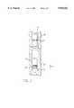
- FIGS. 4 and 5are explanatory diagrams illustrating a possible construction of the downhole transmitter.
- a platform and derrick 3is positioned over a well bore 2.
- the drill string 4is suspended in the well bore with a drill bit 1 attached to its lower end.
- the upper end of the drill string 4is attached to a kelly 7 which is rotated by a rotary table 6.
- the drill string 4is suspended from a hook 8 which is attached to a travelling block (not shown).
- the kelly 7is attached to the hook 8 by means of a rotary swivel 5 which allows the kelly and drill string to rotate relative to the hook 8.
- sensors indicated diagrammatically at 11 to measure well bore and drilling parametersare mounted in the downhole unit 12 and may comprise a plurality of sensors, such as inclinometers and magnetometers to measure bore hole inclination and azimuth, formation evaluation sensors such as scintillation sensors to measure natural formation radiation, electromagnetic wave propagation resistivity sensors to measure formation resistivity, and drilling sensors such as strain gauges to measure weight on bit, rotary torque and bending moment.
- sensorssuch as inclinometers and magnetometers to measure bore hole inclination and azimuth
- formation evaluation sensorssuch as scintillation sensors to measure natural formation radiation
- electromagnetic wave propagation resistivity sensorsto measure formation resistivity
- drilling sensorssuch as strain gauges to measure weight on bit, rotary torque and bending moment.
- the sensor outputsare input to a suitable processing system (not shown) mounted in the downhole unit 12.
- the downhole unit 12also contains a transmitting coil 9 wound on a magnetic or non-magnetic section of the drill string or on a former surrounded by the magnetically permeable material that comprises the drill string.
- the downhole unitalso contains a suitable source of electrical power, such as a battery or a turbine generator driven by drilling fluid. The power source is used to provide power to the sensors, processing system and transmitting coil 9.
- the downhole unit 12also contains an oscillating circuit to create an oscillating carrier signal.
- This oscillating carrier signalis modulated by a modulating circuit such that the modulated oscillating carrier signal is equivalent to the sensor signals.
- the modulated oscillating carrier signalis then fed to the transmitting coil 9.
- the modulating oscillating carrier signal being fed into the transmitting coil 9causes the coil to create a modulated oscillating magnetic field which is then transmitted up the drill string. Since the magnetic permeability of the drill string is comparatively much higher than the magnetic permeability of the formation surrounding the well bore, little magnetic flux energy will leak into the formation, and the majority of the magnetic flux will be transmitted up through the drill string.
- the surface receiving unit 13comprises a power source such as a battery or drilling fluid driven turbine, the output of which is used to power the circuits controlling a magnetometer indicated diagrammatically at 10.
- the magnetometer 10measures the modulated oscillating magnetic flux induced in the drill string by the downhole unit 12.
- the magnetometer 10is a high sensitivity a.c. magnetometer of a kind capable of measuring magnetic flux levels of 10E-15 or greater. This level of sensitivity in the magnetometer is required to facilitate the accurate detection of low levels of magnetic flux energy which result from the magnetic flux energy having been transmitted through large lengths of drill string. Well bores that are drilled to a shallow depth can be handled with magnetometers of low sensitivity.
- the magnetometer outputis connected to a surface receiver circuit 14 and a processor 15 which processes the received data and displays the data. Received data can also be recorded in a surface recorder 16.
- the magnetometer 10is a 3-component gradiometer comprising two identical magnetic field sensors positioned close to one another and so spaced and disposed as to substantially eliminate surface noise generated by electrical, local magnetic or geomagnetic sources.
- Each magnetic field sensorconsists of a monocrystal film of Yttrium Iron Garnet (YIG) grown by liquid phase epitaxy on a Gallium Gadolinium Garnet (GGG) substrate and wound with five coils, two of which are used to produce a rotating magnetic field in the film and three of which are measured coils.
- YIG filmwhich is a ferromagnetic film of high susceptibility and low saturation field, is grown with 111! orientation.
- the measurement coils of each magnetic sensorsupply signals indicative of the magnetic field in the YIG film independently to a respective processing channel associated with each sensor channel, and the information from the two channels is then processed in such a way as to provide a measurement of the gradient of each component of the magnetic field.
- the measurement technique usedmay be a null method in which feedback to the coils is provided to produce a compensating field to cancel the ambient magnetic field.
- Such a gradiometeris supplied by IMC Limited of Salford, England and is described in the paper "Three Component Magnetic Measurement using the Cubic Anisotropy in 111! YIG Films" by A. Y. Perlov, A. I. Voronko, P. M. Vetoschko and V. B. Volkovoy.
- Such a gradiometerprovides simultaneous measurement of the gradient of each component of the magnetic field and is highly sensitive since noise is reduced to a very low level.
- the receiver topologyconsists of two or more sensors positioned either on or within the drill string or alternatively on the ground or sea bed.
- the signals receivedare indicative of flux generated at the transmitter source less the attenuation.
- Other signals receivedare noise components and are typically common mode to the sensors or not from the downhole signal source.
- the signals received by the magnetic sensorsare in the form:
- Fcomrepresents the common mode components and Fsignal 1 and Fsignal 2 represent the components from the downhole signal source.
- the drill stringis of the kind comprising a series of separate drilling pipes connected together end-to-end.
- the tubing along which the magnetic flux signal is transmittedmay be of any other suitable type, provided that it is magnetically permeable.
- the drilling rigmay be of the kind using a coiled tubing unit where the drill string is part of a single continuous coil of tubing.
- the signalinstead of transmitting the magnetic flux signal through a drill string, the signal may be transmitted through production tubing in a producing well, in which case the data sensed at the lower portion of the well bore will normally be production data.
- the tubingmay be separate from the drill string and may, for example, comprise a coiled tubing unit for running downhole sensors into the well bore.
- the systemmay be used to transmit data downhole, for example to control a downhole device, such as a steering system.
- a downhole devicesuch as a steering system.
- the transmitter coilis provided on the drill string at the surface, as indicated diagrammatically at 9a, and the magnetometer is provided downhole, as indicated at 10a.
- FIG. 2illustrates diagrammatically an alternative embodiment of the invention and relates to a so-called "short hop” telemetry system.
- the lower portion of the drill string 17incorporates a mud pulse telemetry MWD system, indicated diagrammatically at 18.
- the mud pulse telemetry MWD systemis mounted in the drill string some distance above the drill bit 19 and is not itself directly electrically connected to a sensor package 20 contained in the downhole unit 21, which is mounted close to the drill bit 19.
- the sensor package 20comprises a plurality of sensors, such as inclinometers and magnetometers to measure bore hole inclination and azimuth, formation evaluation sensors such as scintillation detectors to measure natural formation radiation, electromagnetic wave propagation resistivity sensors to measure formation resistivity, and drilling sensors such as strain gauges to measure weight on bit, rotary torque and bending moment.
- the sensor outputsare input to a suitable processing system mounted in the downhole unit 21.
- the downhole unit 21also contains a transmitting coil, indicated diagrammatically at 22, wound on to the magnetically permeable material that comprises the drill string.
- the downhole unit 21also contains a suitable source of electrical power (not shown) such as a battery or drilling fluid driven turbine generator, which is used to provide power to the sensors, processing system and to the transmitting coil 22.
- the downhole unit 21also contains an oscillating circuit to create an oscillating carrier signal, which is modulated by a modulating circuit such that the modulated oscillating carrier signal is equivalent to the sensor signals. The modulated oscillating carrier signal is fed to the transmitting coil 22.
- the coil 22creates a modulated oscillating magnetic field which is transmitted up the portion of the drill string between the coil 22 and a receiving unit 23. Again, since the magnetic permeability of the drill string is comparatively much higher than the magnetic permeability of the formation surrounding the well bore, little magnetic flux energy will leak into the formation, and the majority of magnetic flux will be transmitted up through the drill string.
- the receiving unit 23is located adjacent the mud pulse telemetry MWD system 18 and comprises a power source (not shown) such as a battery or drilling fluid driven turbine the output of which is used to power the circuits controlling the a.c. magnetometer contained in the receiving unit 23.
- the magnetometermeasures the modulated oscillating magnetic flux transmitted by the downhole unit 21, and the magnetometer output is fed to a processor which then transfers the received sensor data to the mud pulse telemetry MWD system 18, which in turn transmits the data to the surface of the well bore, by means of pulses in the flow of drilling mud, in well known manner.
- This embodimentfacilitates the measurement of drilling and formation parameters close to the drill and the transfer over a short distance (typically less than 300 feet) of the sensor data to a conventional mud pulse telemetry MWD system.
- This arrangementthen requires only the portion of the drill string between the downhole unit 21 and receiving unit 23 to be formed of magnetically permeable material.
- the signal source constituted by the downhole transmitting coilcan be positioned on a magnetic or non-magnetic section of the drill string (that is on a drill pipe or non-magnetic drill collar) or on a former of magnetic or non-magnetic material disposed within the drill string.
- the dipole sourcecan be positioned within the material with the transmitter oriented such that the magnetic flux is coupled in the appropriate direction.
- the flux signalis transmitted in part or completely in the surrounding geological formations.
- the drill pipe or the formationscan be used as the communication channel, or alternatively a combination of the two. Using the formations as the communication channel permits local noise interference received by the surface receiving unit to be minimised due to the fact that the magnetic sensors can be located away from the influence of the moving high permeability material of the drill string.
- the flux signalis transmitted from the downhole transmitting coil 30 within the earth formations 32 to be picked up by an array of receiver magnetometers 31 at the surface.
- the transmitted fluxcan be increased by increasing the permeability of the material on which the transmitting coil is wound, and additionally eddy current losses generated by the alternating magnetic fields induced by the coil can be reduced by the use of high resistivity material to break up the conduction paths within the coil.
- a possible arrangementcomprises a transmitting coil 35 of N turns wound on a conductive former 36 which in turn surrounds a mandrel 38. Furthermore the transmitting coil 35 is accommodated within a non-conductive housing 39 which is in turn received within the magnetic or non-magnetic drill collar or drill pipe 40.
- the conductive former 36is provided with axial slots 41 filled with high resistivity material, such as high permeability ferrite or amorphous alloy material.
- the transmitting coilshould be wound on high permeability high resistivity ferrite or amorphous alloy material to increase the flux and reduce eddy current losses.
- typical conventional sonde configurationsutilise Monel or beryllium copper pressure housings, and a magnetic dipole positioned on or within such a configuration will experience considerable losses.
- the solution to this problemis to mount the transmitting coil within a non-conductive housing made of fibre glass, ceramic or plastic encapsulated material such that the alternating magnetic fields do not induce currents in the material.
- Signal detectioncan be improved by synchronising the receiver and transmitter at the beginning of a data transmission utilising a non-carrier based synchronisation pulse.
- a synchronisation pulsemay be generated as a pressure pulse in the mud column when current is applied to the transmitting coil, where the primary power source is a mud-flow operated turbine generator.
- the synchronisation pressure pulseis detected by a pressure transducer within the mud column which detects a pressure increase due to increased turbine resistance on first applying power to the transmitting coil, and the output from the transducer is processed and used within a phase locked loop to lock the receiver to the transmitter signal, in order to implement a synchronous demodulation system.
Landscapes
- Engineering & Computer Science (AREA)
- Physics & Mathematics (AREA)
- Geology (AREA)
- Mining & Mineral Resources (AREA)
- Remote Sensing (AREA)
- Life Sciences & Earth Sciences (AREA)
- Geophysics (AREA)
- Fluid Mechanics (AREA)
- Environmental & Geological Engineering (AREA)
- Electromagnetism (AREA)
- General Life Sciences & Earth Sciences (AREA)
- Geochemistry & Mineralogy (AREA)
- Geophysics And Detection Of Objects (AREA)
- Earth Drilling (AREA)
- Selective Calling Equipment (AREA)
- Arrangements For Transmission Of Measured Signals (AREA)
- Cable Transmission Systems, Equalization Of Radio And Reduction Of Echo (AREA)
- Radio Relay Systems (AREA)
- Detection And Prevention Of Errors In Transmission (AREA)
Abstract
Description
Fr.sub.1 =Fcom+Fsignal.sub.1
FR.sub.2 =Fcom+Fsignal.sub.2
Claims (19)
Priority Applications (1)
| Application Number | Priority Date | Filing Date | Title |
|---|---|---|---|
| US08/976,084US5818352A (en) | 1994-09-03 | 1997-11-21 | Well data telemetry system |
Applications Claiming Priority (4)
| Application Number | Priority Date | Filing Date | Title |
|---|---|---|---|
| GB9417719AGB9417719D0 (en) | 1994-09-03 | 1994-09-03 | A well data telemetry system |
| GB9417719 | 1994-09-03 | ||
| US52325595A | 1995-09-05 | 1995-09-05 | |
| US08/976,084US5818352A (en) | 1994-09-03 | 1997-11-21 | Well data telemetry system |
Related Parent Applications (1)
| Application Number | Title | Priority Date | Filing Date |
|---|---|---|---|
| US52325595AContinuation | 1994-09-03 | 1995-09-05 |
Publications (1)
| Publication Number | Publication Date |
|---|---|
| US5818352Atrue US5818352A (en) | 1998-10-06 |
Family
ID=10760764
Family Applications (1)
| Application Number | Title | Priority Date | Filing Date |
|---|---|---|---|
| US08/976,084Expired - LifetimeUS5818352A (en) | 1994-09-03 | 1997-11-21 | Well data telemetry system |
Country Status (5)
| Country | Link |
|---|---|
| US (1) | US5818352A (en) |
| EP (1) | EP0699822B1 (en) |
| AT (1) | ATE246308T1 (en) |
| DE (1) | DE69531384T2 (en) |
| GB (1) | GB9417719D0 (en) |
Cited By (74)
| Publication number | Priority date | Publication date | Assignee | Title |
|---|---|---|---|---|
| US20010054969A1 (en)* | 2000-03-28 | 2001-12-27 | Thomeer Hubertus V. | Apparatus and method for downhole well equipment and process management, identification, and actuation |
| US20020050930A1 (en)* | 2000-03-28 | 2002-05-02 | Thomeer Hubertus V. | Apparatus and method for downhole well equipment and process management, identification, and operation |
| US6672409B1 (en) | 2000-10-24 | 2004-01-06 | The Charles Machine Works, Inc. | Downhole generator for horizontal directional drilling |
| US6739413B2 (en) | 2002-01-15 | 2004-05-25 | The Charles Machine Works, Inc. | Using a rotating inner member to drive a tool in a hollow outer member |
| WO2004051402A3 (en)* | 2002-11-27 | 2004-08-12 | Halliburton Energy Serv Inc | Data recovery for pulse telemetry using pulse position modulation |
| US6776240B2 (en) | 2002-07-30 | 2004-08-17 | Schlumberger Technology Corporation | Downhole valve |
| US6788219B2 (en) | 2002-11-27 | 2004-09-07 | Halliburton Energy Services, Inc. | Structure and method for pulse telemetry |
| US20040231851A1 (en)* | 2003-05-20 | 2004-11-25 | Silversmith, Inc. | Wireless well communication system and method |
| US20050056465A1 (en)* | 2003-09-17 | 2005-03-17 | Virally Stephane J. | Automatic downlink system |
| US6915848B2 (en) | 2002-07-30 | 2005-07-12 | Schlumberger Technology Corporation | Universal downhole tool control apparatus and methods |
| US6920085B2 (en) | 2001-02-14 | 2005-07-19 | Halliburton Energy Services, Inc. | Downlink telemetry system |
| US20050189142A1 (en)* | 2004-03-01 | 2005-09-01 | Schlumberger Technology Corporation | Wellbore drilling system and method |
| US20060197678A1 (en)* | 2003-05-20 | 2006-09-07 | David Silvers | Wireless well communication system and method |
| US7347283B1 (en) | 2002-01-15 | 2008-03-25 | The Charles Machine Works, Inc. | Using a rotating inner member to drive a tool in a hollow outer member |
| US20080115934A1 (en)* | 2006-11-20 | 2008-05-22 | Pettinato Miguel H | Multi-Zone Formation Evaluation Systems and Methods |
| US7649474B1 (en) | 2005-11-16 | 2010-01-19 | The Charles Machine Works, Inc. | System for wireless communication along a drill string |
| US20100039285A1 (en)* | 2008-08-12 | 2010-02-18 | Vornbrock Theodore J | Wireless drill string telemetry |
| US20130113491A1 (en)* | 2010-01-27 | 2013-05-09 | Halliburton Energy Services, Inc. | Drilling dynamics monitor |
| WO2015164460A1 (en)* | 2014-04-22 | 2015-10-29 | Schlumberger Canada Limited | Down hole subsurface wave system with drill string wave discrimination and method of using same |
| WO2015179331A1 (en)* | 2014-05-20 | 2015-11-26 | Aps Technology, Inc. | Telemetry system, current sensor, and related methods for a drilling system |
| WO2016061179A1 (en)* | 2014-10-16 | 2016-04-21 | Reme, L.L.C. | Smart lower end |
| WO2016137484A1 (en)* | 2015-02-27 | 2016-09-01 | Halliburton Energy Services, Inc. | System and method for communicating along a casing string including a high magnetic permeability substrate |
| US9541610B2 (en) | 2015-02-04 | 2017-01-10 | Lockheed Martin Corporation | Apparatus and method for recovery of three dimensional magnetic field from a magnetic detection system |
| US9551763B1 (en) | 2016-01-21 | 2017-01-24 | Lockheed Martin Corporation | Diamond nitrogen vacancy sensor with common RF and magnetic fields generator |
| US9557391B2 (en) | 2015-01-23 | 2017-01-31 | Lockheed Martin Corporation | Apparatus and method for high sensitivity magnetometry measurement and signal processing in a magnetic detection system |
| WO2017015704A1 (en)* | 2015-07-24 | 2017-02-02 | Commonwealth Scientific And Industrial Research Organisation | Measuring instruments, systems and magnetic gradiometers |
| US9590601B2 (en) | 2014-04-07 | 2017-03-07 | Lockheed Martin Corporation | Energy efficient controlled magnetic field generator circuit |
| US9614589B1 (en) | 2015-12-01 | 2017-04-04 | Lockheed Martin Corporation | Communication via a magnio |
| US9638821B2 (en) | 2014-03-20 | 2017-05-02 | Lockheed Martin Corporation | Mapping and monitoring of hydraulic fractures using vector magnetometers |
| WO2017123261A1 (en)* | 2016-01-12 | 2017-07-20 | Lockheed Martin Corporation | Defect detector for conductive materials |
| US9720055B1 (en) | 2016-01-21 | 2017-08-01 | Lockheed Martin Corporation | Magnetometer with light pipe |
| US9765613B2 (en) | 2014-03-03 | 2017-09-19 | Aps Technology, Inc. | Drilling system and electromagnetic telemetry tool with an electrical connector assembly and associated methods |
| US9824597B2 (en) | 2015-01-28 | 2017-11-21 | Lockheed Martin Corporation | Magnetic navigation methods and systems utilizing power grid and communication network |
| US9823313B2 (en) | 2016-01-21 | 2017-11-21 | Lockheed Martin Corporation | Diamond nitrogen vacancy sensor with circuitry on diamond |
| US9829545B2 (en) | 2015-11-20 | 2017-11-28 | Lockheed Martin Corporation | Apparatus and method for hypersensitivity detection of magnetic field |
| US9835693B2 (en) | 2016-01-21 | 2017-12-05 | Lockheed Martin Corporation | Higher magnetic sensitivity through fluorescence manipulation by phonon spectrum control |
| US9845153B2 (en) | 2015-01-28 | 2017-12-19 | Lockheed Martin Corporation | In-situ power charging |
| US9853837B2 (en) | 2014-04-07 | 2017-12-26 | Lockheed Martin Corporation | High bit-rate magnetic communication |
| US20180038218A1 (en)* | 2014-06-17 | 2018-02-08 | Halliburton Energy Services, Inc. | Reluctance Sensor for Measuring a Magnetizable Structure in a Subterranean Environment |
| US9910104B2 (en) | 2015-01-23 | 2018-03-06 | Lockheed Martin Corporation | DNV magnetic field detector |
| US9910105B2 (en) | 2014-03-20 | 2018-03-06 | Lockheed Martin Corporation | DNV magnetic field detector |
| US9976413B2 (en) | 2015-02-20 | 2018-05-22 | Aps Technology, Inc. | Pressure locking device for downhole tools |
| US10006973B2 (en) | 2016-01-21 | 2018-06-26 | Lockheed Martin Corporation | Magnetometer with a light emitting diode |
| US10012704B2 (en) | 2015-11-04 | 2018-07-03 | Lockheed Martin Corporation | Magnetic low-pass filter |
| US10088336B2 (en) | 2016-01-21 | 2018-10-02 | Lockheed Martin Corporation | Diamond nitrogen vacancy sensed ferro-fluid hydrophone |
| US10120039B2 (en) | 2015-11-20 | 2018-11-06 | Lockheed Martin Corporation | Apparatus and method for closed loop processing for a magnetic detection system |
| US10126377B2 (en) | 2016-05-31 | 2018-11-13 | Lockheed Martin Corporation | Magneto-optical defect center magnetometer |
| US10145910B2 (en) | 2017-03-24 | 2018-12-04 | Lockheed Martin Corporation | Photodetector circuit saturation mitigation for magneto-optical high intensity pulses |
| US10168393B2 (en) | 2014-09-25 | 2019-01-01 | Lockheed Martin Corporation | Micro-vacancy center device |
| US10190408B2 (en) | 2013-11-22 | 2019-01-29 | Aps Technology, Inc. | System, apparatus, and method for drilling |
| US10228429B2 (en) | 2017-03-24 | 2019-03-12 | Lockheed Martin Corporation | Apparatus and method for resonance magneto-optical defect center material pulsed mode referencing |
| US10241158B2 (en) | 2015-02-04 | 2019-03-26 | Lockheed Martin Corporation | Apparatus and method for estimating absolute axes' orientations for a magnetic detection system |
| US10274550B2 (en) | 2017-03-24 | 2019-04-30 | Lockheed Martin Corporation | High speed sequential cancellation for pulsed mode |
| US10281550B2 (en) | 2016-11-14 | 2019-05-07 | Lockheed Martin Corporation | Spin relaxometry based molecular sequencing |
| US10317279B2 (en) | 2016-05-31 | 2019-06-11 | Lockheed Martin Corporation | Optical filtration system for diamond material with nitrogen vacancy centers |
| US10330744B2 (en) | 2017-03-24 | 2019-06-25 | Lockheed Martin Corporation | Magnetometer with a waveguide |
| US10338164B2 (en) | 2017-03-24 | 2019-07-02 | Lockheed Martin Corporation | Vacancy center material with highly efficient RF excitation |
| US10338162B2 (en) | 2016-01-21 | 2019-07-02 | Lockheed Martin Corporation | AC vector magnetic anomaly detection with diamond nitrogen vacancies |
| US10338163B2 (en) | 2016-07-11 | 2019-07-02 | Lockheed Martin Corporation | Multi-frequency excitation schemes for high sensitivity magnetometry measurement with drift error compensation |
| US10345396B2 (en) | 2016-05-31 | 2019-07-09 | Lockheed Martin Corporation | Selected volume continuous illumination magnetometer |
| US10345395B2 (en) | 2016-12-12 | 2019-07-09 | Lockheed Martin Corporation | Vector magnetometry localization of subsurface liquids |
| US10359479B2 (en) | 2017-02-20 | 2019-07-23 | Lockheed Martin Corporation | Efficient thermal drift compensation in DNV vector magnetometry |
| US10371760B2 (en) | 2017-03-24 | 2019-08-06 | Lockheed Martin Corporation | Standing-wave radio frequency exciter |
| US10371765B2 (en) | 2016-07-11 | 2019-08-06 | Lockheed Martin Corporation | Geolocation of magnetic sources using vector magnetometer sensors |
| US10379174B2 (en) | 2017-03-24 | 2019-08-13 | Lockheed Martin Corporation | Bias magnet array for magnetometer |
| US10408890B2 (en) | 2017-03-24 | 2019-09-10 | Lockheed Martin Corporation | Pulsed RF methods for optimization of CW measurements |
| US20190284927A1 (en)* | 2018-03-13 | 2019-09-19 | Halliburton Energy Services, Inc. | Cased formation parameter data sampling employing an impedance matching directional coupling device |
| US10459041B2 (en) | 2017-03-24 | 2019-10-29 | Lockheed Martin Corporation | Magnetic detection system with highly integrated diamond nitrogen vacancy sensor |
| US10520558B2 (en) | 2016-01-21 | 2019-12-31 | Lockheed Martin Corporation | Diamond nitrogen vacancy sensor with nitrogen-vacancy center diamond located between dual RF sources |
| US10527746B2 (en) | 2016-05-31 | 2020-01-07 | Lockheed Martin Corporation | Array of UAVS with magnetometers |
| US10571530B2 (en) | 2016-05-31 | 2020-02-25 | Lockheed Martin Corporation | Buoy array of magnetometers |
| US10677953B2 (en) | 2016-05-31 | 2020-06-09 | Lockheed Martin Corporation | Magneto-optical detecting apparatus and methods |
| CN112127880A (en)* | 2020-09-27 | 2020-12-25 | 电子科技大学 | A method for measuring ultra-deep resistivity |
| US11060394B2 (en)* | 2018-01-10 | 2021-07-13 | Shell Oil Company | Apparatus and method for downhole measurement |
Citations (7)
| Publication number | Priority date | Publication date | Assignee | Title |
|---|---|---|---|---|
| US3967201A (en)* | 1974-01-25 | 1976-06-29 | Develco, Inc. | Wireless subterranean signaling method |
| US4072200A (en)* | 1976-05-12 | 1978-02-07 | Morris Fred J | Surveying of subterranean magnetic bodies from an adjacent off-vertical borehole |
| US4301408A (en)* | 1978-05-15 | 1981-11-17 | The General Electric Company Limited | Electrical measuring apparatus employing magneto-electric devices |
| US4363137A (en)* | 1979-07-23 | 1982-12-07 | Occidental Research Corporation | Wireless telemetry with magnetic induction field |
| WO1987004028A1 (en)* | 1985-12-20 | 1987-07-02 | Pierre Misson | Magnetic transmission |
| US4800385A (en)* | 1986-12-24 | 1989-01-24 | Radic Co., Ltd. | Well data transmission system using a magnetic drill string for transmitting data as a magnetic flux signal |
| US4992787A (en)* | 1988-09-20 | 1991-02-12 | Teleco Oilfield Services Inc. | Method and apparatus for remote signal entry into measurement while drilling system |
Family Cites Families (1)
| Publication number | Priority date | Publication date | Assignee | Title |
|---|---|---|---|---|
| US4057781A (en)* | 1976-03-19 | 1977-11-08 | Scherbatskoy Serge Alexander | Well bore communication method |
- 1994
- 1994-09-03GBGB9417719Apatent/GB9417719D0/enactivePending
- 1995
- 1995-09-04EPEP95306160Apatent/EP0699822B1/ennot_activeExpired - Lifetime
- 1995-09-04DEDE69531384Tpatent/DE69531384T2/ennot_activeExpired - Lifetime
- 1995-09-04ATAT95306160Tpatent/ATE246308T1/ennot_activeIP Right Cessation
- 1997
- 1997-11-21USUS08/976,084patent/US5818352A/ennot_activeExpired - Lifetime
Patent Citations (7)
| Publication number | Priority date | Publication date | Assignee | Title |
|---|---|---|---|---|
| US3967201A (en)* | 1974-01-25 | 1976-06-29 | Develco, Inc. | Wireless subterranean signaling method |
| US4072200A (en)* | 1976-05-12 | 1978-02-07 | Morris Fred J | Surveying of subterranean magnetic bodies from an adjacent off-vertical borehole |
| US4301408A (en)* | 1978-05-15 | 1981-11-17 | The General Electric Company Limited | Electrical measuring apparatus employing magneto-electric devices |
| US4363137A (en)* | 1979-07-23 | 1982-12-07 | Occidental Research Corporation | Wireless telemetry with magnetic induction field |
| WO1987004028A1 (en)* | 1985-12-20 | 1987-07-02 | Pierre Misson | Magnetic transmission |
| US4800385A (en)* | 1986-12-24 | 1989-01-24 | Radic Co., Ltd. | Well data transmission system using a magnetic drill string for transmitting data as a magnetic flux signal |
| US4992787A (en)* | 1988-09-20 | 1991-02-12 | Teleco Oilfield Services Inc. | Method and apparatus for remote signal entry into measurement while drilling system |
Cited By (106)
| Publication number | Priority date | Publication date | Assignee | Title |
|---|---|---|---|---|
| US20020050930A1 (en)* | 2000-03-28 | 2002-05-02 | Thomeer Hubertus V. | Apparatus and method for downhole well equipment and process management, identification, and operation |
| US20010054969A1 (en)* | 2000-03-28 | 2001-12-27 | Thomeer Hubertus V. | Apparatus and method for downhole well equipment and process management, identification, and actuation |
| US7385523B2 (en) | 2000-03-28 | 2008-06-10 | Schlumberger Technology Corporation | Apparatus and method for downhole well equipment and process management, identification, and operation |
| US6989764B2 (en) | 2000-03-28 | 2006-01-24 | Schlumberger Technology Corporation | Apparatus and method for downhole well equipment and process management, identification, and actuation |
| US6672409B1 (en) | 2000-10-24 | 2004-01-06 | The Charles Machine Works, Inc. | Downhole generator for horizontal directional drilling |
| US6920085B2 (en) | 2001-02-14 | 2005-07-19 | Halliburton Energy Services, Inc. | Downlink telemetry system |
| US6739413B2 (en) | 2002-01-15 | 2004-05-25 | The Charles Machine Works, Inc. | Using a rotating inner member to drive a tool in a hollow outer member |
| US7347283B1 (en) | 2002-01-15 | 2008-03-25 | The Charles Machine Works, Inc. | Using a rotating inner member to drive a tool in a hollow outer member |
| US7025152B2 (en) | 2002-01-15 | 2006-04-11 | The Charles Machine Works, Inc. | Using a rotating inner member to drive a tool in a hollow outer member |
| US20050056460A1 (en)* | 2002-01-15 | 2005-03-17 | The Charles Machine Works, Inc. | Using a rotating inner member to drive a tool in a hollow outer member |
| US6915848B2 (en) | 2002-07-30 | 2005-07-12 | Schlumberger Technology Corporation | Universal downhole tool control apparatus and methods |
| US6776240B2 (en) | 2002-07-30 | 2004-08-17 | Schlumberger Technology Corporation | Downhole valve |
| US6788219B2 (en) | 2002-11-27 | 2004-09-07 | Halliburton Energy Services, Inc. | Structure and method for pulse telemetry |
| WO2004051402A3 (en)* | 2002-11-27 | 2004-08-12 | Halliburton Energy Serv Inc | Data recovery for pulse telemetry using pulse position modulation |
| US6963290B2 (en) | 2002-11-27 | 2005-11-08 | Halliburton Energy Services, Inc. | Data recovery for pulse telemetry using pulse position modulation |
| US20040231851A1 (en)* | 2003-05-20 | 2004-11-25 | Silversmith, Inc. | Wireless well communication system and method |
| US20060197678A1 (en)* | 2003-05-20 | 2006-09-07 | David Silvers | Wireless well communication system and method |
| US7242317B2 (en) | 2003-05-20 | 2007-07-10 | Silversmith, Inc. | Wireless well communication system and method |
| US7198102B2 (en) | 2003-09-17 | 2007-04-03 | Schlumberger Technology Corporation | Automatic downlink system |
| US7320370B2 (en) | 2003-09-17 | 2008-01-22 | Schlumberger Technology Corporation | Automatic downlink system |
| US7380616B2 (en) | 2003-09-17 | 2008-06-03 | Schlumberger Technology Corporation | Automatic downlink system |
| US20050056465A1 (en)* | 2003-09-17 | 2005-03-17 | Virally Stephane J. | Automatic downlink system |
| US20050189142A1 (en)* | 2004-03-01 | 2005-09-01 | Schlumberger Technology Corporation | Wellbore drilling system and method |
| US7832500B2 (en) | 2004-03-01 | 2010-11-16 | Schlumberger Technology Corporation | Wellbore drilling method |
| US8305229B1 (en) | 2005-11-16 | 2012-11-06 | The Charles Machine Works, Inc. | System for wireless communication along a drill string |
| US7649474B1 (en) | 2005-11-16 | 2010-01-19 | The Charles Machine Works, Inc. | System for wireless communication along a drill string |
| US20080115934A1 (en)* | 2006-11-20 | 2008-05-22 | Pettinato Miguel H | Multi-Zone Formation Evaluation Systems and Methods |
| US8132621B2 (en) | 2006-11-20 | 2012-03-13 | Halliburton Energy Services, Inc. | Multi-zone formation evaluation systems and methods |
| US20100039285A1 (en)* | 2008-08-12 | 2010-02-18 | Vornbrock Theodore J | Wireless drill string telemetry |
| US8242929B2 (en)* | 2008-08-12 | 2012-08-14 | Raytheon Company | Wireless drill string telemetry |
| US20130113491A1 (en)* | 2010-01-27 | 2013-05-09 | Halliburton Energy Services, Inc. | Drilling dynamics monitor |
| US9465128B2 (en)* | 2010-01-27 | 2016-10-11 | Halliburton Energy Services, Inc. | Drilling dynamics monitor |
| US10190408B2 (en) | 2013-11-22 | 2019-01-29 | Aps Technology, Inc. | System, apparatus, and method for drilling |
| US9765613B2 (en) | 2014-03-03 | 2017-09-19 | Aps Technology, Inc. | Drilling system and electromagnetic telemetry tool with an electrical connector assembly and associated methods |
| US9910105B2 (en) | 2014-03-20 | 2018-03-06 | Lockheed Martin Corporation | DNV magnetic field detector |
| US9638821B2 (en) | 2014-03-20 | 2017-05-02 | Lockheed Martin Corporation | Mapping and monitoring of hydraulic fractures using vector magnetometers |
| US10725124B2 (en) | 2014-03-20 | 2020-07-28 | Lockheed Martin Corporation | DNV magnetic field detector |
| US9823381B2 (en) | 2014-03-20 | 2017-11-21 | Lockheed Martin Corporation | Mapping and monitoring of hydraulic fractures using vector magnetometers |
| US9853837B2 (en) | 2014-04-07 | 2017-12-26 | Lockheed Martin Corporation | High bit-rate magnetic communication |
| US10277208B2 (en) | 2014-04-07 | 2019-04-30 | Lockheed Martin Corporation | Energy efficient controlled magnetic field generator circuit |
| US9590601B2 (en) | 2014-04-07 | 2017-03-07 | Lockheed Martin Corporation | Energy efficient controlled magnetic field generator circuit |
| WO2015164460A1 (en)* | 2014-04-22 | 2015-10-29 | Schlumberger Canada Limited | Down hole subsurface wave system with drill string wave discrimination and method of using same |
| WO2015179331A1 (en)* | 2014-05-20 | 2015-11-26 | Aps Technology, Inc. | Telemetry system, current sensor, and related methods for a drilling system |
| US9790784B2 (en) | 2014-05-20 | 2017-10-17 | Aps Technology, Inc. | Telemetry system, current sensor, and related methods for a drilling system |
| US10544670B2 (en)* | 2014-06-17 | 2020-01-28 | Halliburton Energy Services, Inc. | Reluctance sensor for measuring a magnetizable structure in a subterranean environment |
| US20180038218A1 (en)* | 2014-06-17 | 2018-02-08 | Halliburton Energy Services, Inc. | Reluctance Sensor for Measuring a Magnetizable Structure in a Subterranean Environment |
| US10168393B2 (en) | 2014-09-25 | 2019-01-01 | Lockheed Martin Corporation | Micro-vacancy center device |
| US9766094B2 (en) | 2014-10-16 | 2017-09-19 | Reme, L.L.C. | Smart lower end |
| WO2016061179A1 (en)* | 2014-10-16 | 2016-04-21 | Reme, L.L.C. | Smart lower end |
| US10466312B2 (en) | 2015-01-23 | 2019-11-05 | Lockheed Martin Corporation | Methods for detecting a magnetic field acting on a magneto-optical detect center having pulsed excitation |
| US9910104B2 (en) | 2015-01-23 | 2018-03-06 | Lockheed Martin Corporation | DNV magnetic field detector |
| US9557391B2 (en) | 2015-01-23 | 2017-01-31 | Lockheed Martin Corporation | Apparatus and method for high sensitivity magnetometry measurement and signal processing in a magnetic detection system |
| US9845153B2 (en) | 2015-01-28 | 2017-12-19 | Lockheed Martin Corporation | In-situ power charging |
| US9824597B2 (en) | 2015-01-28 | 2017-11-21 | Lockheed Martin Corporation | Magnetic navigation methods and systems utilizing power grid and communication network |
| US9541610B2 (en) | 2015-02-04 | 2017-01-10 | Lockheed Martin Corporation | Apparatus and method for recovery of three dimensional magnetic field from a magnetic detection system |
| US10241158B2 (en) | 2015-02-04 | 2019-03-26 | Lockheed Martin Corporation | Apparatus and method for estimating absolute axes' orientations for a magnetic detection system |
| US10408889B2 (en) | 2015-02-04 | 2019-09-10 | Lockheed Martin Corporation | Apparatus and method for recovery of three dimensional magnetic field from a magnetic detection system |
| US9976413B2 (en) | 2015-02-20 | 2018-05-22 | Aps Technology, Inc. | Pressure locking device for downhole tools |
| WO2016137484A1 (en)* | 2015-02-27 | 2016-09-01 | Halliburton Energy Services, Inc. | System and method for communicating along a casing string including a high magnetic permeability substrate |
| GB2551912A (en)* | 2015-02-27 | 2018-01-03 | Halliburton Energy Services Inc | System and method for communicating along a casing string including a high magnetic permeability substrate |
| AU2015384170B2 (en)* | 2015-02-27 | 2018-08-23 | Halliburton Energy Services, Inc. | System and method for communicating along a casing string including a high magnetic permeability substrate |
| US10655458B2 (en) | 2015-02-27 | 2020-05-19 | Halliburton Energy Services, Inc. | System and method for communicating along a casing string including a high magnetic permeability substrate |
| US10626720B2 (en) | 2015-07-24 | 2020-04-21 | Commonwealth Scientific And Industrial Research Organisation | Measuring instruments, systems and magnetic gradiometers |
| WO2017015704A1 (en)* | 2015-07-24 | 2017-02-02 | Commonwealth Scientific And Industrial Research Organisation | Measuring instruments, systems and magnetic gradiometers |
| US10012704B2 (en) | 2015-11-04 | 2018-07-03 | Lockheed Martin Corporation | Magnetic low-pass filter |
| US9829545B2 (en) | 2015-11-20 | 2017-11-28 | Lockheed Martin Corporation | Apparatus and method for hypersensitivity detection of magnetic field |
| US10120039B2 (en) | 2015-11-20 | 2018-11-06 | Lockheed Martin Corporation | Apparatus and method for closed loop processing for a magnetic detection system |
| US10333588B2 (en) | 2015-12-01 | 2019-06-25 | Lockheed Martin Corporation | Communication via a magnio |
| US9614589B1 (en) | 2015-12-01 | 2017-04-04 | Lockheed Martin Corporation | Communication via a magnio |
| WO2017123261A1 (en)* | 2016-01-12 | 2017-07-20 | Lockheed Martin Corporation | Defect detector for conductive materials |
| US10088452B2 (en) | 2016-01-12 | 2018-10-02 | Lockheed Martin Corporation | Method for detecting defects in conductive materials based on differences in magnetic field characteristics measured along the conductive materials |
| US9835693B2 (en) | 2016-01-21 | 2017-12-05 | Lockheed Martin Corporation | Higher magnetic sensitivity through fluorescence manipulation by phonon spectrum control |
| US9835694B2 (en) | 2016-01-21 | 2017-12-05 | Lockheed Martin Corporation | Higher magnetic sensitivity through fluorescence manipulation by phonon spectrum control |
| US10006973B2 (en) | 2016-01-21 | 2018-06-26 | Lockheed Martin Corporation | Magnetometer with a light emitting diode |
| US10338162B2 (en) | 2016-01-21 | 2019-07-02 | Lockheed Martin Corporation | AC vector magnetic anomaly detection with diamond nitrogen vacancies |
| US9720055B1 (en) | 2016-01-21 | 2017-08-01 | Lockheed Martin Corporation | Magnetometer with light pipe |
| US9823313B2 (en) | 2016-01-21 | 2017-11-21 | Lockheed Martin Corporation | Diamond nitrogen vacancy sensor with circuitry on diamond |
| US10088336B2 (en) | 2016-01-21 | 2018-10-02 | Lockheed Martin Corporation | Diamond nitrogen vacancy sensed ferro-fluid hydrophone |
| US10520558B2 (en) | 2016-01-21 | 2019-12-31 | Lockheed Martin Corporation | Diamond nitrogen vacancy sensor with nitrogen-vacancy center diamond located between dual RF sources |
| US9551763B1 (en) | 2016-01-21 | 2017-01-24 | Lockheed Martin Corporation | Diamond nitrogen vacancy sensor with common RF and magnetic fields generator |
| US9817081B2 (en) | 2016-01-21 | 2017-11-14 | Lockheed Martin Corporation | Magnetometer with light pipe |
| US9823314B2 (en) | 2016-01-21 | 2017-11-21 | Lockheed Martin Corporation | Magnetometer with a light emitting diode |
| US10527746B2 (en) | 2016-05-31 | 2020-01-07 | Lockheed Martin Corporation | Array of UAVS with magnetometers |
| US10317279B2 (en) | 2016-05-31 | 2019-06-11 | Lockheed Martin Corporation | Optical filtration system for diamond material with nitrogen vacancy centers |
| US10345396B2 (en) | 2016-05-31 | 2019-07-09 | Lockheed Martin Corporation | Selected volume continuous illumination magnetometer |
| US10126377B2 (en) | 2016-05-31 | 2018-11-13 | Lockheed Martin Corporation | Magneto-optical defect center magnetometer |
| US10677953B2 (en) | 2016-05-31 | 2020-06-09 | Lockheed Martin Corporation | Magneto-optical detecting apparatus and methods |
| US10571530B2 (en) | 2016-05-31 | 2020-02-25 | Lockheed Martin Corporation | Buoy array of magnetometers |
| US10371765B2 (en) | 2016-07-11 | 2019-08-06 | Lockheed Martin Corporation | Geolocation of magnetic sources using vector magnetometer sensors |
| US10338163B2 (en) | 2016-07-11 | 2019-07-02 | Lockheed Martin Corporation | Multi-frequency excitation schemes for high sensitivity magnetometry measurement with drift error compensation |
| US10281550B2 (en) | 2016-11-14 | 2019-05-07 | Lockheed Martin Corporation | Spin relaxometry based molecular sequencing |
| US10345395B2 (en) | 2016-12-12 | 2019-07-09 | Lockheed Martin Corporation | Vector magnetometry localization of subsurface liquids |
| US10359479B2 (en) | 2017-02-20 | 2019-07-23 | Lockheed Martin Corporation | Efficient thermal drift compensation in DNV vector magnetometry |
| US10459041B2 (en) | 2017-03-24 | 2019-10-29 | Lockheed Martin Corporation | Magnetic detection system with highly integrated diamond nitrogen vacancy sensor |
| US10330744B2 (en) | 2017-03-24 | 2019-06-25 | Lockheed Martin Corporation | Magnetometer with a waveguide |
| US10379174B2 (en) | 2017-03-24 | 2019-08-13 | Lockheed Martin Corporation | Bias magnet array for magnetometer |
| US10274550B2 (en) | 2017-03-24 | 2019-04-30 | Lockheed Martin Corporation | High speed sequential cancellation for pulsed mode |
| US10371760B2 (en) | 2017-03-24 | 2019-08-06 | Lockheed Martin Corporation | Standing-wave radio frequency exciter |
| US10228429B2 (en) | 2017-03-24 | 2019-03-12 | Lockheed Martin Corporation | Apparatus and method for resonance magneto-optical defect center material pulsed mode referencing |
| US10145910B2 (en) | 2017-03-24 | 2018-12-04 | Lockheed Martin Corporation | Photodetector circuit saturation mitigation for magneto-optical high intensity pulses |
| US10408890B2 (en) | 2017-03-24 | 2019-09-10 | Lockheed Martin Corporation | Pulsed RF methods for optimization of CW measurements |
| US10338164B2 (en) | 2017-03-24 | 2019-07-02 | Lockheed Martin Corporation | Vacancy center material with highly efficient RF excitation |
| US11060394B2 (en)* | 2018-01-10 | 2021-07-13 | Shell Oil Company | Apparatus and method for downhole measurement |
| US20190284927A1 (en)* | 2018-03-13 | 2019-09-19 | Halliburton Energy Services, Inc. | Cased formation parameter data sampling employing an impedance matching directional coupling device |
| US11073014B2 (en)* | 2018-03-13 | 2021-07-27 | Halliburton Energy Services, Inc. | Cased formation parameter data sampling employing an impedance matching directional coupling device |
| CN112127880A (en)* | 2020-09-27 | 2020-12-25 | 电子科技大学 | A method for measuring ultra-deep resistivity |
Also Published As
| Publication number | Publication date |
|---|---|
| DE69531384T2 (en) | 2004-06-09 |
| DE69531384D1 (en) | 2003-09-04 |
| EP0699822A3 (en) | 1997-01-29 |
| ATE246308T1 (en) | 2003-08-15 |
| EP0699822A2 (en) | 1996-03-06 |
| EP0699822B1 (en) | 2003-07-30 |
| GB9417719D0 (en) | 1994-10-19 |
Similar Documents
| Publication | Publication Date | Title |
|---|---|---|
| US5818352A (en) | Well data telemetry system | |
| US4800385A (en) | Well data transmission system using a magnetic drill string for transmitting data as a magnetic flux signal | |
| CA1146220A (en) | Electromagnetic sensing device | |
| US5402068A (en) | Method and apparatus for logging-while-drilling with improved performance through cancellation of systemic errors through combination of signals, utilization of dedicated transmitter drivers, and utilization of selected reference signals | |
| US4845434A (en) | Magnetometer circuitry for use in bore hole detection of AC magnetic fields | |
| EP0105801B1 (en) | Well logging apparatus and method using transverse magnetic mode | |
| CA1210062A (en) | Apparatus and method for logging wells while drilling | |
| CN100504444C (en) | Subsurface Electromagnetic Surveys Using Crossed Magnetic Dipoles | |
| EP0792407B1 (en) | Single-wire guidance system for drilling boreholes | |
| CA2245720C (en) | Well logging method and apparatus for nmr and resistivity measurements | |
| US4107598A (en) | Electromagnetic wave logging system for determining resistivity and dielectric constant of earth formations | |
| US20100259268A1 (en) | Electromagnetic logging between a cased borehole and surface | |
| CA2164809A1 (en) | Virtual induction sonde for steering transmitted and received signals | |
| US20050264293A1 (en) | Downhole signal source | |
| JP2009503308A (en) | Interactive drilling string telemetry system for measurement and drilling control | |
| CN103080777B (en) | Equipment and method for micro-resistivity imaging in non-conductive drilling fluid | |
| GB2371870A (en) | Subsurface reservoir monitoring | |
| US4383220A (en) | Microwave electromagnetic borehole dipmeter | |
| EP0540425B1 (en) | Method and apparatus for investigating earth formations | |
| GB2292869A (en) | A Well Data Telemetry System | |
| US5208539A (en) | Method for determining electromagnetically the locations of underground ore deposits | |
| GB2299915A (en) | Communication along a drill string | |
| US10502799B2 (en) | Fiber optic nuclear magnetic resonance sensor | |
| GB2235296A (en) | Apparatus for use in a borehole to measure an electrical parameter of the formation surrounding the borehole | |
| US6968735B2 (en) | Long range data transmitter for horizontal directional drilling |
Legal Events
| Date | Code | Title | Description |
|---|---|---|---|
| FEPP | Fee payment procedure | Free format text:PAYOR NUMBER ASSIGNED (ORIGINAL EVENT CODE: ASPN); ENTITY STATUS OF PATENT OWNER: LARGE ENTITY | |
| STCF | Information on status: patent grant | Free format text:PATENTED CASE | |
| FEPP | Fee payment procedure | Free format text:PAT HOLDER NO LONGER CLAIMS SMALL ENTITY STATUS, ENTITY STATUS SET TO UNDISCOUNTED (ORIGINAL EVENT CODE: STOL); ENTITY STATUS OF PATENT OWNER: LARGE ENTITY | |
| REFU | Refund | Free format text:REFUND - PAYMENT OF MAINTENANCE FEE, 4TH YR, SMALL ENTITY (ORIGINAL EVENT CODE: R283); ENTITY STATUS OF PATENT OWNER: LARGE ENTITY | |
| FPAY | Fee payment | Year of fee payment:4 | |
| FEPP | Fee payment procedure | Free format text:ENTITY STATUS SET TO UNDISCOUNTED (ORIGINAL EVENT CODE: BIG.); ENTITY STATUS OF PATENT OWNER: LARGE ENTITY | |
| FPAY | Fee payment | Year of fee payment:8 | |
| AS | Assignment | Owner name:DAILEY IDS LIMITED, UNITED KINGDOM Free format text:CHANGE OF NAME;ASSIGNOR:INTEGRATED DRILLING SERVICES LIMITED;REEL/FRAME:017656/0838 Effective date:19980522 | |
| AS | Assignment | Owner name:TARGET WELL CONTROL LIMITED, UNITED KINGDOM Free format text:AGREEMENT FOR JOINTLY OWNED TECHNOLOGY;ASSIGNOR:DAILEY IDS LIMITED;REEL/FRAME:017675/0152 Effective date:20000707 Owner name:WEATHERFORD U.S., L.P., TEXAS Free format text:AGREEMENT FOR JOINTLY OWNED TECHNOLOGY;ASSIGNOR:DAILEY IDS LIMITED;REEL/FRAME:017675/0152 Effective date:20000707 | |
| FPAY | Fee payment | Year of fee payment:12 |