US5817975A - Housing with integral mounting bracket - Google Patents
Housing with integral mounting bracketDownload PDFInfo
- Publication number
- US5817975A US5817975AUS08/531,585US53158595AUS5817975AUS 5817975 AUS5817975 AUS 5817975AUS 53158595 AUS53158595 AUS 53158595AUS 5817975 AUS5817975 AUS 5817975A
- Authority
- US
- United States
- Prior art keywords
- lid
- bracket
- housing
- side walls
- combination
- Prior art date
- Legal status (The legal status is an assumption and is not a legal conclusion. Google has not performed a legal analysis and makes no representation as to the accuracy of the status listed.)
- Expired - Fee Related
Links
- 239000002184metalSubstances0.000description6
- 238000003466weldingMethods0.000description4
- 238000004519manufacturing processMethods0.000description3
- 239000010426asphaltSubstances0.000description1
- 239000003990capacitorSubstances0.000description1
- 238000004140cleaningMethods0.000description1
- 150000001875compoundsChemical class0.000description1
- 238000010276constructionMethods0.000description1
- 238000005260corrosionMethods0.000description1
- 230000007797corrosionEffects0.000description1
- 238000011031large-scale manufacturing processMethods0.000description1
- 238000000034methodMethods0.000description1
- 238000003860storageMethods0.000description1
- 238000004804windingMethods0.000description1
Images
Classifications
- H—ELECTRICITY
- H01—ELECTRIC ELEMENTS
- H01F—MAGNETS; INDUCTANCES; TRANSFORMERS; SELECTION OF MATERIALS FOR THEIR MAGNETIC PROPERTIES
- H01F27/00—Details of transformers or inductances, in general
- H01F27/02—Casings
Definitions
- the inventionrelates to a housing that has a central section for holding an object and a lid for the central section with the lid having an integral bracket used to mount the housing.
- a housingfor a ballast transformer.
- This housinghas a central section, commonly called a can, in which the transformer components and wires are placed.
- the canhas an open top which is closed by a lid.
- the can or cover of a conventional housingis usually provided with tabs having slots through which screws are placed.
- the ballast transformer housingin a different manner. This includes, for example, hanging the transformer from a wire or a rail.
- the bracketsare of generally U-shape and connected to one of the can's side walls by a suitable fastener, such as a rivet, or by welding.
- a suitable fastenersuch as a rivet
- weldingcannot be accomplished without first cleaning off a space to which the bracket would be fastened. This adds a step to the manufacturing process.
- rivetsare suitable fasteners, they are relatively costly in the sense that they require extra components, the rivets and brackets, and the extra manufacturing step of riveting the brackets to the can. In the use of either welding or rivets, a separate bracket piece must be manufactured, stored and handled.
- the present inventionrelates to a housing that has an integral mounting bracket.
- a housing for a ballast transformerthere is can for holding the transformer components and a lid sealed to the can.
- a bracketis integrally formed on the lid.
- the lid and its integral bracketare made in one step by forming a metal blank, such as by die stamping. Therefore, an integral hanger of any desired shape and size can be made that is consistent with the forming process and the size of the lid being made.
- the inventionis cost effective in that it saves on the separate forming, handling and attaching of the separate bracket parts such as used in the prior art.
- An additional objectis to provide a housing for a ballast transformer having an open top main section, or can, holding the ballast transformer and other components, and a lid of a shape conforming to the central section for covering the open top, with the lid having an integrally formed mounting bracket.
- Yet another objectis to provide a transformer housing including a can and a lid with the lid having an integrally formed bracket to mount the housing.
- FIG. 1is an exploded perspective view of a ballast transformer made according to the prior art
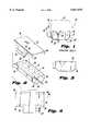
- FIG. 2is an exploded perspective view of a ballast made in accordance with the subject invention
- FIG. 3is an elevational view showing the lid assembled to the can.
- FIG. 4is a top view of the blank used in forming the lid.
- FIG. 1shows a prior art design of a ballast transformer generally designated 10.
- Its housingincludes a generally rectangular can 14 of metal, which is usually stamped, having sidewalls 16, end walls 18, and a bottom wall 19. The can is chamfered between the side walls and the bottom wall, as shown most clearly in FIG. 2, although this is not necessary.
- the can 14can be of any desired length and width.
- the side and end walls 16 and 18define an open top.
- the can 14Located within the can 14 are a number of components, illustratively shown as core 17 of the transformer and its windings.
- the can 14can also contain other components, such as, for example, one or more terminal boards, one or more capacitors and resistors for the ballast circuit, etc. These are not shown.
- One of the end walls 18has a cutout 20 through which wires 22 to be connected to the ballast transformer within the can 14 are passed.
- the transformer and associated componentsare relatively heavy and a typical ballast can weight from 4 to 10 pounds.
- a lid 30is provided that has a top 32 and downwardly extending side walls, or lips, 34.
- Lid 30is also of metal and is made by stamping.
- the size and shape of the lidcorresponds to the size and shape of the can's open top so that it can completely seal the can.
- itis filled with a suitable asphaltic compound and when the top 30 is placed over the can, the overflow of the asphalt and a pressure fit of the lid 30 seals the lid to the can.
- the outer surfaces of the can and lidare usually painted to minimize corrosion. All of this is conventional.
- the housing of FIG. 1has a separate bracket 40 attached to one of its side walls 16. Attachment is accomplished by one or more rivets 42 inserted through one or more holes in the bracket.
- the bracket 40is shown as being generally U-shaped although other shapes, such as L, are possible.
- the bracket 40is elongated and extends along a selected portion of the length of the can side wall 16, for example, about the middle third of the length of the can side wall. A bracket of such length would typically require two or three rivets to securely fasten it to the can.
- Several brackets 40may be used along the length of the can. If several brackets are used, each requires its own set of rivets for fastening.
- FIGS. 2 and 3show a preferred embodiment of the subject invention.
- the same reference numeralshave been used for the same components shown in FIG. 1.
- the can 14 and its internal componentsare of the same construction as previously described.
- the lid 30has one of its lips 35 integrally formed with a generally U-shaped bracket 36. That is, the lid is stamped from a blank of metal with the bracket 36 being formed during the stamping. No welding or other fasteners are used for the bracket.
- the bracket 36has a leg 37 that projects and continues downwardly from the lid lip 35, a curved center portion 38 and an upwardly extending leg 39. If desired, the curved center portion 38 can be made flat. The length of the legs 37 and 39 can be made shorter or longer, as desired. Also, after the bracket is formed, leg 39 can be deformed inwardly to decrease the width of the opening into the bracket.
- the length of the bracket 36is shown as being about one-third the length of the lid and the bracket is shown as being centered on the lid.
- the bracketcan be formed in sections, for example, one bracket 36 near each end of the lid and another bracket in the center. Any combination of bracket section length and spacing can be used as desired.
- FIG. 3shows the lid 30 attached to the can 14.
- the lid 30is seated on the can 14 and fastened to it in the same manner as in the prior art design of FIG. 1. No change in tooling is needed for seating and fastening the lid to the can since no part of the bracket 36 extends above the lid top 32.
- the bottom center part 38 of bracket 36extends only part way down the height of the can side walls, here shown above the chamfered corners of the can 16.
- FIG. 4shows a layout of the blank that is used for stamping of the lid 30.
- the blankis shown with fold lines 42 along the lid length.
- the bracket 36is an extension of the lid top.
- the blankis inserted into a suitable die such that when stamping pressure is applied, the lips 34, 35 are bent downwardly along lines 42.
- a male part of the dieengages the bracket part 36 of the blank to form the U-shape bracket.
- the stampingcan be either in a single step or in several sequential steps, as is conventional.
- bracket 36is an integral part of the lid 30, no separate bracket and attendant fastening elements, such as screws or rivets, and no separate fastening step are needed. Therefore, the cost for making the housing with the bracket 36 is only increased by the extra metal added to the blank that is needed to make the bracket. This is basically not an extra cost since a separate bracket also requires metal. In addition, it requires a separate forming die and forming step.
- a novel housingwhich has a central section, or can, with an open top covered by a lid.
- the lidhas an integral bracket to permit the housing to be mounted to an external surface, such as a wire or rail.
- the lid with integral bracketrequires no separate fastener components, no manufacture, storage and handling of the separate fastener components, and fastening of the separate fastener components to any part of the housing.
Landscapes
- Engineering & Computer Science (AREA)
- Power Engineering (AREA)
- Casings For Electric Apparatus (AREA)
Abstract
Description
Claims (7)
Priority Applications (1)
| Application Number | Priority Date | Filing Date | Title |
|---|---|---|---|
| US08/531,585US5817975A (en) | 1995-09-21 | 1995-09-21 | Housing with integral mounting bracket |
Applications Claiming Priority (1)
| Application Number | Priority Date | Filing Date | Title |
|---|---|---|---|
| US08/531,585US5817975A (en) | 1995-09-21 | 1995-09-21 | Housing with integral mounting bracket |
Publications (1)
| Publication Number | Publication Date |
|---|---|
| US5817975Atrue US5817975A (en) | 1998-10-06 |
Family
ID=24118247
Family Applications (1)
| Application Number | Title | Priority Date | Filing Date |
|---|---|---|---|
| US08/531,585Expired - Fee RelatedUS5817975A (en) | 1995-09-21 | 1995-09-21 | Housing with integral mounting bracket |
Country Status (1)
| Country | Link |
|---|---|
| US (1) | US5817975A (en) |
Cited By (26)
| Publication number | Priority date | Publication date | Assignee | Title |
|---|---|---|---|---|
| US6045400A (en)* | 1999-04-29 | 2000-04-04 | General Motors Corporation | Electrical connector and connector slide-in mounting bracket arrangement |
| USD452486S1 (en) | 2000-02-22 | 2001-12-25 | Emerson Electric Co. | DIN clip for housing unit |
| US20070261375A1 (en)* | 2006-05-15 | 2007-11-15 | Oreck Holdings, Llc | Filter system for an air cleaner |
| USD570782S1 (en)* | 2007-05-31 | 2008-06-10 | Cooper Technologies Company | Ground fault circuit interrupter |
| US10366840B1 (en)* | 2017-02-07 | 2019-07-30 | American Radionic Company, Inc. | Capacitor with multiple elements for multiple replacement applications |
| US10586655B1 (en) | 2018-12-28 | 2020-03-10 | American Radionic Company, Inc. | Capacitor with multiple elements for multiple replacement applications |
| USD906247S1 (en) | 2019-07-11 | 2020-12-29 | American Radionic Company, Inc. | Capacitor |
| US11177074B1 (en) | 2005-04-07 | 2021-11-16 | Amrad Manufacturing, Llc | Capacitor for multiple replacement applications |
| US11183341B1 (en) | 2006-12-29 | 2021-11-23 | Amrad Manufacturing, Llc | Electrolytic capacitive device |
| US11183337B1 (en) | 2005-04-07 | 2021-11-23 | Amrad Manufacturing, Llc | Capacitor with multiple elements for multiple replacement applications |
| US11183336B2 (en) | 2005-04-07 | 2021-11-23 | Amrad Manufacturing, Llc | Capacitor with multiple elements for multiple replacement applications |
| US11183338B2 (en) | 2005-04-07 | 2021-11-23 | Amrad Manufacturing, Llc | Capacitor with multiple elements for multiple replacement applications |
| US11183335B2 (en) | 2013-05-21 | 2021-11-23 | Amrad Manufacturing, Llc | Power factor correction capacitors |
| US11189426B1 (en) | 2005-04-07 | 2021-11-30 | Amrad Manufacturing, Llc | Capacitor with multiple elements for multiple replacement applications |
| US11195663B2 (en) | 2017-05-12 | 2021-12-07 | Amrad Manufacturing, Llc | Capacitor with multiple elements for multiple replacement applications |
| USD938912S1 (en) | 2005-12-23 | 2021-12-21 | Amrad Manufacturing, Llc | Capacitor |
| US11424077B1 (en) | 2017-12-13 | 2022-08-23 | Amrad Manufacturing, Llc | Hard start kit for multiple replacement applications |
| US11575298B2 (en) | 2021-04-30 | 2023-02-07 | Amrad Manufacturing, Llc | Hard start kit for multiple replacement applications |
| US12125645B1 (en) | 2019-06-07 | 2024-10-22 | Amrad Manufacturing, Llc | Capacitor with multiple elements for multiple replacement applications |
| USD1052528S1 (en) | 2019-06-25 | 2024-11-26 | Amrad Manufacturing, Llc | Capacitor |
| USD1054379S1 (en) | 2020-11-24 | 2024-12-17 | Amrad Manufacturing, Llc | Capacitor with relay |
| USD1055860S1 (en) | 2018-12-13 | 2024-12-31 | Amrad Manufacturing, Llc | Magnet for attachment to a capacitor |
| US12224131B1 (en) | 2009-11-13 | 2025-02-11 | Amrad Manufacturing, Llc | Hard start kit for multiple replacement applications |
| US12260998B2 (en) | 2005-04-07 | 2025-03-25 | Amrad Manufacturing, Llc | Capacitor with multiple elements for multiple replacement applications |
| US12272503B2 (en) | 2017-05-12 | 2025-04-08 | Amrad Manufacturing, Llc | Capacitor with multiple elements for multiple replacement applications |
| US12437918B2 (en) | 2023-09-22 | 2025-10-07 | Amrad Manufacturing, Llc | Capacitor mount |
Citations (4)
| Publication number | Priority date | Publication date | Assignee | Title |
|---|---|---|---|---|
| US2740905A (en)* | 1954-01-04 | 1956-04-03 | Gen Electric | Reactive device |
| US4199072A (en)* | 1978-01-26 | 1980-04-22 | Jacks Kenneth R | Detachable street light base terminal cabinet |
| US5177325A (en)* | 1989-12-20 | 1993-01-05 | A. J. Giammanco & Associates, Inc. | Housing for electric transformer |
| US5192227A (en)* | 1991-12-23 | 1993-03-09 | Square D Company | Din rail mounting bracket |
- 1995
- 1995-09-21USUS08/531,585patent/US5817975A/ennot_activeExpired - Fee Related
Patent Citations (4)
| Publication number | Priority date | Publication date | Assignee | Title |
|---|---|---|---|---|
| US2740905A (en)* | 1954-01-04 | 1956-04-03 | Gen Electric | Reactive device |
| US4199072A (en)* | 1978-01-26 | 1980-04-22 | Jacks Kenneth R | Detachable street light base terminal cabinet |
| US5177325A (en)* | 1989-12-20 | 1993-01-05 | A. J. Giammanco & Associates, Inc. | Housing for electric transformer |
| US5192227A (en)* | 1991-12-23 | 1993-03-09 | Square D Company | Din rail mounting bracket |
Cited By (48)
| Publication number | Priority date | Publication date | Assignee | Title |
|---|---|---|---|---|
| US6045400A (en)* | 1999-04-29 | 2000-04-04 | General Motors Corporation | Electrical connector and connector slide-in mounting bracket arrangement |
| USD452486S1 (en) | 2000-02-22 | 2001-12-25 | Emerson Electric Co. | DIN clip for housing unit |
| US11189426B1 (en) | 2005-04-07 | 2021-11-30 | Amrad Manufacturing, Llc | Capacitor with multiple elements for multiple replacement applications |
| US12272501B2 (en) | 2005-04-07 | 2025-04-08 | Amrad Manufacturing, Llc | Capacitor for multiple replacement applications |
| US11651903B1 (en) | 2005-04-07 | 2023-05-16 | Amrad Manufacturing, Llc | Capacitor for multiple replacement applications |
| US12230452B1 (en) | 2005-04-07 | 2025-02-18 | Amrad Manufacturing, Llc | Capacitor with multiple elements for multiple replacement applications |
| US12224132B1 (en) | 2005-04-07 | 2025-02-11 | Amrad Manufacturing, Llc | Capacitor with multiple elements for multiple replacement applications |
| US12260998B2 (en) | 2005-04-07 | 2025-03-25 | Amrad Manufacturing, Llc | Capacitor with multiple elements for multiple replacement applications |
| US11177074B1 (en) | 2005-04-07 | 2021-11-16 | Amrad Manufacturing, Llc | Capacitor for multiple replacement applications |
| US12278059B2 (en) | 2005-04-07 | 2025-04-15 | Amrad Manufacturing, Llc | Capacitor with multiple elements for multiple replacement applications |
| US11183337B1 (en) | 2005-04-07 | 2021-11-23 | Amrad Manufacturing, Llc | Capacitor with multiple elements for multiple replacement applications |
| US11183336B2 (en) | 2005-04-07 | 2021-11-23 | Amrad Manufacturing, Llc | Capacitor with multiple elements for multiple replacement applications |
| US11183338B2 (en) | 2005-04-07 | 2021-11-23 | Amrad Manufacturing, Llc | Capacitor with multiple elements for multiple replacement applications |
| USD1045798S1 (en) | 2005-12-23 | 2024-10-08 | Amrad Manufacturing, Llc | Capacitor |
| USD938912S1 (en) | 2005-12-23 | 2021-12-21 | Amrad Manufacturing, Llc | Capacitor |
| US20070261375A1 (en)* | 2006-05-15 | 2007-11-15 | Oreck Holdings, Llc | Filter system for an air cleaner |
| US7722694B2 (en) | 2006-05-15 | 2010-05-25 | Oreck Holdings, Llc | Filter system for an air cleaner |
| US11183341B1 (en) | 2006-12-29 | 2021-11-23 | Amrad Manufacturing, Llc | Electrolytic capacitive device |
| US11631550B2 (en) | 2006-12-29 | 2023-04-18 | Amrad Manufacturing, Llc | Electrolytic capacitor with multiple sections |
| US12293879B2 (en) | 2006-12-29 | 2025-05-06 | Amrad Manufacturing, Llc | Electrolytic capacitive device |
| USD570782S1 (en)* | 2007-05-31 | 2008-06-10 | Cooper Technologies Company | Ground fault circuit interrupter |
| US12237115B1 (en) | 2009-11-13 | 2025-02-25 | Amrad Manufacturing Llc | Hard start kit for multiple replacement applications |
| US12224131B1 (en) | 2009-11-13 | 2025-02-11 | Amrad Manufacturing, Llc | Hard start kit for multiple replacement applications |
| US11189425B1 (en) | 2013-05-21 | 2021-11-30 | Amrad Manufacturing, Llc | Power factor correction capacitors |
| US11183335B2 (en) | 2013-05-21 | 2021-11-23 | Amrad Manufacturing, Llc | Power factor correction capacitors |
| US12230451B2 (en) | 2013-05-21 | 2025-02-18 | Amrad Manufacturing, Llc | Power factor correction capacitors |
| US10366840B1 (en)* | 2017-02-07 | 2019-07-30 | American Radionic Company, Inc. | Capacitor with multiple elements for multiple replacement applications |
| US12211655B2 (en) | 2017-05-12 | 2025-01-28 | Amrad Manufacturing, Llc | Capacitor with multiple elements for multiple replacement applications |
| US12191087B2 (en) | 2017-05-12 | 2025-01-07 | Amrad Manufacturing, Llc | Capacitor with multiple elements for multiple replacement applications |
| US12260997B2 (en) | 2017-05-12 | 2025-03-25 | Amrad Manufacturing, Llc | Capacitor with multiple elements for multiple replacement applications |
| US12308179B2 (en) | 2017-05-12 | 2025-05-20 | Amrad Manufacturing, Llc | Capacitor with multiple elements for multiple replacement applications |
| US12272503B2 (en) | 2017-05-12 | 2025-04-08 | Amrad Manufacturing, Llc | Capacitor with multiple elements for multiple replacement applications |
| US11195663B2 (en) | 2017-05-12 | 2021-12-07 | Amrad Manufacturing, Llc | Capacitor with multiple elements for multiple replacement applications |
| US11424077B1 (en) | 2017-12-13 | 2022-08-23 | Amrad Manufacturing, Llc | Hard start kit for multiple replacement applications |
| USD1055860S1 (en) | 2018-12-13 | 2024-12-31 | Amrad Manufacturing, Llc | Magnet for attachment to a capacitor |
| US12230447B2 (en) | 2018-12-28 | 2025-02-18 | Amrad Manufacturing, Llc | Capacitor with multiple elements for multiple replacement applications |
| US11183330B2 (en) | 2018-12-28 | 2021-11-23 | Amrad Manufacturing, Llc | Capacitor with multiple elements for multiple replacement applications |
| US10586655B1 (en) | 2018-12-28 | 2020-03-10 | American Radionic Company, Inc. | Capacitor with multiple elements for multiple replacement applications |
| US12315679B2 (en) | 2018-12-28 | 2025-05-27 | Amrad Manufacturing, Llc | Capacitor with multiple elements for multiple replacement applications |
| US12125645B1 (en) | 2019-06-07 | 2024-10-22 | Amrad Manufacturing, Llc | Capacitor with multiple elements for multiple replacement applications |
| USD1054986S1 (en) | 2019-06-25 | 2024-12-24 | Amrad Manufacturing, Llc | Capacitor |
| USD1052528S1 (en) | 2019-06-25 | 2024-11-26 | Amrad Manufacturing, Llc | Capacitor |
| USD1059290S1 (en) | 2019-07-11 | 2025-01-28 | Amrad Manufacturing, Llc | Capacitor |
| USD906247S1 (en) | 2019-07-11 | 2020-12-29 | American Radionic Company, Inc. | Capacitor |
| USD1054379S1 (en) | 2020-11-24 | 2024-12-17 | Amrad Manufacturing, Llc | Capacitor with relay |
| US12260991B2 (en) | 2021-04-30 | 2025-03-25 | Amrad Manufacturing, Llc | Hard start kit for multiple replacement applications |
| US11575298B2 (en) | 2021-04-30 | 2023-02-07 | Amrad Manufacturing, Llc | Hard start kit for multiple replacement applications |
| US12437918B2 (en) | 2023-09-22 | 2025-10-07 | Amrad Manufacturing, Llc | Capacitor mount |
Similar Documents
| Publication | Publication Date | Title |
|---|---|---|
| US5817975A (en) | Housing with integral mounting bracket | |
| US5075831A (en) | Lighting fixture assembly | |
| USRE38881E1 (en) | Plastic building wall mount assembly | |
| US6359220B2 (en) | Electrical block | |
| US6588782B2 (en) | Running boards and methods of constructing a running board | |
| US4279368A (en) | Stanchion assembly | |
| US6281439B1 (en) | Electrical box with enhanced support for carrying fixtures | |
| US6429371B2 (en) | Electrical block | |
| US5538277A (en) | Passenger air bag module fastenerless cover attachment | |
| US5682017A (en) | Metal outlet box with snap together base and cover | |
| CA2106518A1 (en) | Bumper Mounting Construction | |
| US4932181A (en) | Base assembly for an open office partition panel | |
| US6303859B1 (en) | Electrical box with reinforced and locked support for carrying fixtures | |
| US5307327A (en) | Mounting assembly for automotive audio components | |
| US4352521A (en) | Mounting element with threaded member attached to a body wall of an automotive vehicle | |
| CA2233299A1 (en) | Container unit with two shoulders | |
| US4039135A (en) | Coupling device | |
| US5249099A (en) | Steel ballast enclosure having integral mounting bosses and mounting flanges | |
| JPS5940797Y2 (en) | cabinet equipment | |
| JPH0248345Y2 (en) | ||
| JPS6224515Y2 (en) | ||
| JPS6339944Y2 (en) | ||
| JP2552232Y2 (en) | Kasagi mounting structure | |
| JPS6144333Y2 (en) | ||
| US5240208A (en) | Terminal block panel mount |
Legal Events
| Date | Code | Title | Description |
|---|---|---|---|
| AS | Assignment | Owner name:MAGNETEK, INC., TENNESSEE Free format text:ASSIGNMENT OF ASSIGNORS INTEREST;ASSIGNOR:HEILMANN, RON;REEL/FRAME:007885/0851 Effective date:19951109 | |
| AS | Assignment | Owner name:UNIVERSAL LIGHTING TECHNOLOGIES, INC., TENNESSEE Free format text:ASSIGNMENT OF ASSIGNORS INTEREST;ASSIGNOR:MAGNETEK, INC.;REEL/FRAME:011898/0908 Effective date:20010615 | |
| AS | Assignment | Owner name:FLEET CAPITAL CORPORATION, GEORGIA Free format text:SECURITY INTEREST;ASSIGNOR:UNIVERSAL LIGHTING TECHNOLOGIES, INC.;REEL/FRAME:012177/0912 Effective date:20010615 | |
| AS | Assignment | Owner name:UNIVERSAL LIGHTING TECHNOLOGIES, INC., TENNESSEE Free format text:ASSIGNMENT OF ASSIGNORS INTEREST;ASSIGNOR:MAGNETEK, INC.;REEL/FRAME:012124/0443 Effective date:20010615 | |
| FPAY | Fee payment | Year of fee payment:4 | |
| AS | Assignment | Owner name:BACK BAY CAPITAL FUNDING LLC, MASSACHUSETTS Free format text:SECURITY AGREEMENT;ASSIGNOR:UNIVERSAL LIGHTING TECHNOLOGIES, INC.;REEL/FRAME:015377/0396 Effective date:20041021 | |
| FEPP | Fee payment procedure | Free format text:PAYOR NUMBER ASSIGNED (ORIGINAL EVENT CODE: ASPN); ENTITY STATUS OF PATENT OWNER: LARGE ENTITY | |
| FPAY | Fee payment | Year of fee payment:8 | |
| AS | Assignment | Owner name:UNIVERSAL LIGHTING TECHNOLOGIES, INC., TENNESSEE Free format text:RELEASE BY SECURED PARTY;ASSIGNOR:BANK OF AMERICA, N.A.;REEL/FRAME:020299/0935 Effective date:20071220 | |
| AS | Assignment | Owner name:UNIVERSAL LIGHTING TECHNOLOGIES, INC., TENNESSEE Free format text:RELEASE BY SECURED PARTY;ASSIGNOR:BACK BAY CAPITAL FUNDING LLC;REEL/FRAME:020339/0410 Effective date:20071220 | |
| REMI | Maintenance fee reminder mailed | ||
| LAPS | Lapse for failure to pay maintenance fees | ||
| STCH | Information on status: patent discontinuation | Free format text:PATENT EXPIRED DUE TO NONPAYMENT OF MAINTENANCE FEES UNDER 37 CFR 1.362 | |
| FP | Lapsed due to failure to pay maintenance fee | Effective date:20101006 |