US5817206A - Selective laser sintering of polymer powder of controlled particle size distribution - Google Patents
Selective laser sintering of polymer powder of controlled particle size distributionDownload PDFInfo
- Publication number
- US5817206A US5817206AUS08/597,805US59780596AUS5817206AUS 5817206 AUS5817206 AUS 5817206AUS 59780596 AUS59780596 AUS 59780596AUS 5817206 AUS5817206 AUS 5817206A
- Authority
- US
- United States
- Prior art keywords
- powder
- article
- particles
- selective laser
- laser sintering
- Prior art date
- Legal status (The legal status is an assumption and is not a legal conclusion. Google has not performed a legal analysis and makes no representation as to the accuracy of the status listed.)
- Expired - Lifetime
Links
Images


Classifications
- C—CHEMISTRY; METALLURGY
- C08—ORGANIC MACROMOLECULAR COMPOUNDS; THEIR PREPARATION OR CHEMICAL WORKING-UP; COMPOSITIONS BASED THEREON
- C08J—WORKING-UP; GENERAL PROCESSES OF COMPOUNDING; AFTER-TREATMENT NOT COVERED BY SUBCLASSES C08B, C08C, C08F, C08G or C08H
- C08J3/00—Processes of treating or compounding macromolecular substances
- C08J3/12—Powdering or granulating
- C08J3/122—Pulverisation by spraying
- B—PERFORMING OPERATIONS; TRANSPORTING
- B29—WORKING OF PLASTICS; WORKING OF SUBSTANCES IN A PLASTIC STATE IN GENERAL
- B29C—SHAPING OR JOINING OF PLASTICS; SHAPING OF MATERIAL IN A PLASTIC STATE, NOT OTHERWISE PROVIDED FOR; AFTER-TREATMENT OF THE SHAPED PRODUCTS, e.g. REPAIRING
- B29C64/00—Additive manufacturing, i.e. manufacturing of three-dimensional [3D] objects by additive deposition, additive agglomeration or additive layering, e.g. by 3D printing, stereolithography or selective laser sintering
- B29C64/10—Processes of additive manufacturing
- B29C64/141—Processes of additive manufacturing using only solid materials
- B29C64/153—Processes of additive manufacturing using only solid materials using layers of powder being selectively joined, e.g. by selective laser sintering or melting
- B—PERFORMING OPERATIONS; TRANSPORTING
- B29—WORKING OF PLASTICS; WORKING OF SUBSTANCES IN A PLASTIC STATE IN GENERAL
- B29C—SHAPING OR JOINING OF PLASTICS; SHAPING OF MATERIAL IN A PLASTIC STATE, NOT OTHERWISE PROVIDED FOR; AFTER-TREATMENT OF THE SHAPED PRODUCTS, e.g. REPAIRING
- B29C67/00—Shaping techniques not covered by groups B29C39/00 - B29C65/00, B29C70/00 or B29C73/00
- B—PERFORMING OPERATIONS; TRANSPORTING
- B33—ADDITIVE MANUFACTURING TECHNOLOGY
- B33Y—ADDITIVE MANUFACTURING, i.e. MANUFACTURING OF THREE-DIMENSIONAL [3-D] OBJECTS BY ADDITIVE DEPOSITION, ADDITIVE AGGLOMERATION OR ADDITIVE LAYERING, e.g. BY 3-D PRINTING, STEREOLITHOGRAPHY OR SELECTIVE LASER SINTERING
- B33Y10/00—Processes of additive manufacturing
- B—PERFORMING OPERATIONS; TRANSPORTING
- B33—ADDITIVE MANUFACTURING TECHNOLOGY
- B33Y—ADDITIVE MANUFACTURING, i.e. MANUFACTURING OF THREE-DIMENSIONAL [3-D] OBJECTS BY ADDITIVE DEPOSITION, ADDITIVE AGGLOMERATION OR ADDITIVE LAYERING, e.g. BY 3-D PRINTING, STEREOLITHOGRAPHY OR SELECTIVE LASER SINTERING
- B33Y40/00—Auxiliary operations or equipment, e.g. for material handling
- B33Y40/10—Pre-treatment
- B—PERFORMING OPERATIONS; TRANSPORTING
- B33—ADDITIVE MANUFACTURING TECHNOLOGY
- B33Y—ADDITIVE MANUFACTURING, i.e. MANUFACTURING OF THREE-DIMENSIONAL [3-D] OBJECTS BY ADDITIVE DEPOSITION, ADDITIVE AGGLOMERATION OR ADDITIVE LAYERING, e.g. BY 3-D PRINTING, STEREOLITHOGRAPHY OR SELECTIVE LASER SINTERING
- B33Y40/00—Auxiliary operations or equipment, e.g. for material handling
- B33Y40/20—Post-treatment, e.g. curing, coating or polishing
- B—PERFORMING OPERATIONS; TRANSPORTING
- B33—ADDITIVE MANUFACTURING TECHNOLOGY
- B33Y—ADDITIVE MANUFACTURING, i.e. MANUFACTURING OF THREE-DIMENSIONAL [3-D] OBJECTS BY ADDITIVE DEPOSITION, ADDITIVE AGGLOMERATION OR ADDITIVE LAYERING, e.g. BY 3-D PRINTING, STEREOLITHOGRAPHY OR SELECTIVE LASER SINTERING
- B33Y70/00—Materials specially adapted for additive manufacturing
- C—CHEMISTRY; METALLURGY
- C08—ORGANIC MACROMOLECULAR COMPOUNDS; THEIR PREPARATION OR CHEMICAL WORKING-UP; COMPOSITIONS BASED THEREON
- C08J—WORKING-UP; GENERAL PROCESSES OF COMPOUNDING; AFTER-TREATMENT NOT COVERED BY SUBCLASSES C08B, C08C, C08F, C08G or C08H
- C08J2325/00—Characterised by the use of homopolymers or copolymers of compounds having one or more unsaturated aliphatic radicals, each having only one carbon-to-carbon double bond, and at least one being terminated by an aromatic carbocyclic ring; Derivatives of such polymers
- C08J2325/02—Homopolymers or copolymers of hydrocarbons
- C08J2325/04—Homopolymers or copolymers of styrene
- C—CHEMISTRY; METALLURGY
- C08—ORGANIC MACROMOLECULAR COMPOUNDS; THEIR PREPARATION OR CHEMICAL WORKING-UP; COMPOSITIONS BASED THEREON
- C08J—WORKING-UP; GENERAL PROCESSES OF COMPOUNDING; AFTER-TREATMENT NOT COVERED BY SUBCLASSES C08B, C08C, C08F, C08G or C08H
- C08J2333/00—Characterised by the use of homopolymers or copolymers of compounds having one or more unsaturated aliphatic radicals, each having only one carbon-to-carbon double bond, and only one being terminated by only one carboxyl radical, or of salts, anhydrides, esters, amides, imides, or nitriles thereof; Derivatives of such polymers
- C08J2333/04—Characterised by the use of homopolymers or copolymers of compounds having one or more unsaturated aliphatic radicals, each having only one carbon-to-carbon double bond, and only one being terminated by only one carboxyl radical, or of salts, anhydrides, esters, amides, imides, or nitriles thereof; Derivatives of such polymers esters
- C08J2333/06—Characterised by the use of homopolymers or copolymers of compounds having one or more unsaturated aliphatic radicals, each having only one carbon-to-carbon double bond, and only one being terminated by only one carboxyl radical, or of salts, anhydrides, esters, amides, imides, or nitriles thereof; Derivatives of such polymers esters of esters containing only carbon, hydrogen, and oxygen, the oxygen atom being present only as part of the carboxyl radical
Definitions
- This inventionis in the field of rapid prototyping, and is more specifically directed to materials for use in the fabrication of three-dimensional articles and molds by way of selective laser sintering.
- Rapid prototypinggenerally refers to the manufacture of articles, or molds within which the articles are to be formed, directly from computer-aided-design (CAD) data bases in an automated fashion, as opposed to conventional machining of prototype articles from engineering drawings.
- CADcomputer-aided-design
- a rapid prototyping technologyis the selective laser sintering process practiced by systems available from DTM Corporation of Austin, Tex.
- articlesare produced in layerwise fashion from a laser-fusible powder that is dispensed one layer at a time. Portions of each layer of powder are fused, or sintered, by the application of laser energy directed in raster scan fashion at those locations of the layer of powder corresponding to the cross-section of the article to be formed in that layer as indicated by a CAD data base. Additional layers of powder are dispensed and selectively fused in similar fashion, with fused portions of adjacent layers fusing to one another to form a three-dimensional article.
- Detailed description of the selective laser sintering technologymay be found in U.S. Pat.
- rapid prototyping technologyin general, and selective laser sintering specifically, may be used to form a prototype article or part directly from various materials, including plastics.
- Such prototype articlesare useful in visually checking computer models and for form fit evaluation; if the articles have sufficient strength, the prototypes may undergo some amount of functional testing and evaluation.
- rapid prototypingmay be used to form a positive representation (commonly referred to as a pattern or master) of an article that is to be molded, in which case a mold will be formed around the pattern, for use in injection molding, investment casting, and the like. Molds of various types may be formed in this way.
- ceramic mold shells for investment casting of metalsmay be formed by surrounding the master with a ceramic material and curing the ceramic at a sufficiently high temperature, during which the master decomposes into an ash.
- Silicone-based rubber moldsmay also be formed in a similar manner as "soft" tools, for the molding of limited numbers of plastic parts.
- metal mold diesmay be formed by spraying metal around the pattern, followed by infiltrating the metal with a binder.
- Plastic powdersare often used in the selective laser sintering process, both in the fabrication of prototype articles and also in the fabrication of patterns or masters for molds.
- plasticssuch as polycarbonate, ABS, nylon 11, and acrylic-based copolymers such as Zeneca A369, in connection with selective laser sintering is well known in the art.
- These powdersare typically produced by the grinding of pellets, and as such the powders typically have average particle sizes in a range of from about 50 ⁇ to about 125 ⁇ .
- the feature definition and surface finish of articles produced by the selective laser sintering of these conventional powdersis relatively limited, however, by these large particle sizes.
- the smoothness and regularity of the surface of an article formed by selective laser sinteringalso depends upon the shape of the powder particles. Particles formed by grinding tend to have irregular shapes, which translate into rough surfaces for the articles made therefrom, even if the ground powder is processed to the smaller end of the distribution (e.g., an average particle size of 50 ⁇ ). Because of the large particle size and also the irregular shape of the particles in conventional powders, significant effort and cost is involved in sanding the article surface to the desired smoothness, especially for use as a mold master or pattern.
- powders of small particle sizesare desirable for selective laser sintering as such powders allow definition of high resolution edges and result in smooth surfaces of the article.
- a substantial fraction of the powderis of a particle size that is too small (e.g., less than 15 ⁇ in diameter)
- the dispensing of a new layer of powder on top of a previously selectively sintered layermay cause fissures and gashes in the top surfaces of the article, as high interparticle friction among the excessively small particles results in a high in-plane shear force.
- a powder having a high fraction of excessively small particle sizeswill also adversely affect the "rough breakout" process, in which the article is removed from its surrounding powder after completion of the selective laser sintering process.
- Another limitation on the particle size distributionrelates to the thermal processing of the powder into the article.
- this controlis obtained by heating the powder at the target surface with a radiant heater, and also by drawing temperature controlled gas, such as nitrogen, through the powder bed.
- powders having excessively small particle sizesare particularly susceptible to unwanted sintering resulting from the temperature control of the powder and article formed therein, because smaller particles sinter to one another at a faster rate than do larger particles under the same time and temperature conditions.
- spray dryingconsists of atomizing or otherwise forming small droplets of an emulsion by way of a rotary spray nozzle.
- the dropletsare sprayed into a heated environment, so that the water in the emulsion evaporates, yielding a powder of the solute that is in substantially solid spherical particles.
- air classificationis a known process for deriving a desired distribution of particle sizes of a material.
- air classificationseparates particles in a powder by size, through the application of centrifugal force to a mixture of powder and air by way of a cyclone separator. Particles of different sizes are displaced to different distances, with the larger particles (i.e., heavier particles, assuming uniform density) displaced further from the center of the separator apparatus by the turbulent force.
- the inventionmay be implemented by preparing a fine powder of a polymer that is capable of being readily emulsified and subjecting the powder to selective laser sintering.
- polymers suitable for use in such a powderinclude acrylics and styrene, both homopolymers and copolymers thereof.
- the powderis produced by spray drying an emulsion to produce particles of substantially spherical shape.
- the distribution of particle sizes for the spray dried particlesis tuned by way of air classifying, resulting in a powder that has a mean particle diameter in a range of approximately 20 microns to approximately 50 microns, with less than approximately 5% of the particles (volume average) of a diameter less than 15 microns.
- the glass transition temperature of the powderis elevated above room temperature, preferably to a range of 30° C. to 100° C., to facilitate rough breakout and surface finishing.
- Articles formed by the selective laser sintering of such a powderpreferably have a density of between approximately 55% and approximately 75% of theoretical, and as such are well suited for use as patterns for investment casting of metals and as masters for silicone-based rubber molds, despite the relatively high coefficient of thermal expansion of the polymer.
- FIGS. 1a and 1bare perspective cutaway and schematic views of a selective laser sintering system for fabricating an article according to the preferred embodiment of the invention.
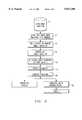
- FIG. 2is a flow chart illustrating the method of fabricating an article or mold according to the preferred embodiment of the invention.
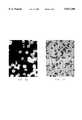
- FIGS. 3a and 3bare microphotographs of a powder produced according to the preferred embodiment of the invention, illustrating the substantially spherical shape of the particles therein.
- FIGS. 4a and 4bare plots of a particle size distribution for a copolymer powder useful in selective laser sintering according to the preferred embodiment of the invention, at various stages of the powder production process.
- FIG. 5is a plan view of a target surface in the system of FIGS. 1a and 1b illustrating the use of raster bars in the selective laser sintering process.
- FIG. 6is a cross-sectional elevation view of the part bed in the system of FIGS. 1a and 1b illustrating the use of bases in the selective laser sintering process.
- FIGS. 1a and 1bthe construction and operation of a selective laser sintering system 100 will first be described, for purposes of explanation of the preferred embodiment of the present invention.
- selective laser sintering system 100includes a chamber 102 (front doors and the top of chamber 102 not shown in FIG. 1a, for purposes of clarity) within which selective laser sintering process 10 takes place.
- Target surface 104refers to the top surface of a heat-fusible powder (including portions previously sintered, if present) disposed on part piston 106; the volume of sintered and unsintered powder disposed upon part piston 6 will be referred to herein as part bed 107.
- the vertical motion of part piston 106is controlled by motor 108.
- Laser 110provides a beam which is directed by scanning system 142 in the manner described in the U.S. Patents referred to hereinabove and as shown in FIG. 1b.
- FIG. 1billustrates laser 110 and scanning system 142.
- Laser 110includes, in addition to a laser itself, such conventional control elements as described in the above-referenced U.S. Pat. No. 4,863,538, for example a safety shutter, a front mirror assembly, and focusing elements such as diverging and converging lenses.
- the type of laser 110 usedis, of course, dependent upon many factors and in particular upon the type of powder that is to be sintered.
- a Nd/YAG type lasermay be used, preferably with a controllable power output.
- Laser 110is preferably controllable to be modulated on and off; while on, laser 110 produces laser beam 105 which travels generally along the path shown by the arrows in FIG. 1b.
- Computer 140 and scanning system 142are also included for controlling the direction of the laser beam as it impinges target surface 104.
- computer 140includes a microprocessor for controlling laser 110 and further includes a CAD/CAM system for generating the data that defines the dimensions of the article being produced.
- a conventional personal computer workstationsuch as a personal computer based on a Pentium-class microprocessor and including floating point capabilities, is suitable for use as computer 140 in the preferred embodiment of the invention.
- Scanning system 142includes prism 144 for redirecting the path of travel of laser beam 105; the number of prisms 144 necessary for directing laser beam 105 to the proper location is based on the physical layout of the apparatus. Alternatively, as is well known in the art, one or more fixed mirrors can be used in place of prism 144 for directing laser beam 105, depending upon the particular layout of system 100.
- Scanning system 142further includes a pair of mirrors 146, 147 which are driven by respective galvanometers 148, 149. Galvanometers 148, 149 are coupled to their respective mirrors 146, 147 to selectively orient the mirrors 146, 147 and control the aim of laser beam 105.
- Galvanometers 148, 149are mounted perpendicularly to one another so that mirrors 146, 147 are mounted nominally at a right angle relative to one another.
- a function generator driver in scanning system 142controls the movement of galvanometers 148, 149 to control the aim of laser beam 105 within target surface 104, in conjunction with its on and off modulation controlled by computer 140, according to CAD/CAM data stored within computer 140 that defines the cross-section of the article to be formed in the layer of powder at target surface 104.
- alternative scanning systemsmay be used in place of scanning system 142 described hereinabove, including such apparatus as acoustic-optic scanners, rotating polygonal mirrors, and resonant mirror scanners.
- delivery of the fusible powderis accomplished in system 100 by way of powder, or feed, piston 114, controlled by motor 116, in combination with counter-rotating roller 118.
- counter-rotating roller 118transfers the powder lifted above the floor of chamber 102 to target surface 104 in a uniform and level fashion. It may be preferred to provide two powder pistons 114 on either side of part piston 106, for purposes of efficient and flexible powder deliver, as used in the SINTERSTATION 2000 system available from DTM Corporation.
- selective laser sintering process 10begins by system 100 performing process 12 to dispense a layer of powder over target surface 104.
- powderis delivered by feed piston 114 moving upwardly to place a volume of powder into chamber 102.
- Roller 118preferably provided with a scraper to prevent buildup, such scraper not shown in FIG. 1a for clarity
- target surface 104(whether or not a prior layer is disposed thereat) is preferably below the floor of chamber 102 by a small amount, for example 5 mils, to define the thickness of the laser of powder to now be processed. It is preferable, for smooth and thorough distribution of the powder, that the amount of powder provided by feed piston 114 be greater than that which can be accepted by part piston 106, so that some excess powder will result from the motion of roller 118 across target surface 104; this may be accomplished by the raising of feed piston 114 above the floor of chamber 102 by a greater distance that the distance below the floor of chamber 102 that part piston 106 is lowered (e.g., 10 mils versus 5 mils). It is also preferable to slave the counter-rotation of roller 118 to the translation of roller 118 within chamber 102, so that the ratio of rotational speed to translation speed is constant.
- Target surface 104is typically a previously dispensed layer of powder, whether or not portions of the article have been formed therein; alternatively, as will be described in further detail hereinbelow, target surface 104 may be a solid substrate that is in place in part piston 106 and upon which the article will be formed. While a wide range of materials may be used in connection with selective laser sintering system 100, the powder used according to this embodiment of the invention is a polymer powder.
- laser beam 105is then scanned over the layer in raster scan fashion, for example by scanning in the x-direction and incrementally stepping in the y-direction after each scan, to selectively fuse the portion of the powder corresponding to the cross-section of the article to be formed in that layer.
- the next layer of powderis dispensed thereover and the process repeated, often with a differently-shaped cross-section of the article being formed, depending upon the CAD data base representation of the article.
- the methodis used in conjunction with a polymer emulsion 2 to form a powder.
- the polymer of polymer emulsion 2may be an acrylic or acrylate (e.g., methyl methacrylate, butyl methacrylate), or styrene, either as a homopolymer or as a copolymer thereof, as such materials may be readily placed into an emulsion.
- the preferred set of polymers used in emulsion 2preferably have glass transition temperatures that are well above room temperature, preferably in a range of about 30° C. to about 100° C.
- a preferred example of the polymer emulsion 2is an acrylic-based copolymer emulsion, such as A639 acrylic copolymer, available from Zeneca, diluted with water to a solids content of between approximately 20 percent and 30 percent.
- Polymer emulsion 2is then subjected to spray drying process 4 to form a powder.
- spray drying of emulsionsis a conventional technique in the formation of powders.
- spray drying of polymer emulsion 2 in process 4is preferred over conventional grinding, because spray drying will yield a powder of substantially spherical particles while the particles produced by the grinding of polymer pellets are quite irregular in shape.
- FIGS. 3a and 3bare microphotographs of a powder formed by the spray drying of A639 acrylic-based copolymer according to the preferred embodiment of the invention, in which the substantial sphericity of particles in the powder is quite evident.
- Process 4is preferably performed so as to provide a mean particle diameter (by volume) of less than about 50 ⁇ , preferably between about 20 ⁇ and about 50 ⁇ .
- the distribution of particle sizes, or diameters, about the mean particle size as produced by spray dryingis typically a normal distribution.
- the small average particle size provided by the spray drying of process 4 according to this embodiment of the inventionprovides important advantages in selective laser sintering, particularly in achieving excellent feature resolution and definition in the article produced. It has been observed, in connection with the present invention, that articles with sharper edges and smooth surfaces are more readily produced from powders having a small mean particle size.
- part bed 107the powder is provided by way of a radiant heater, and via a temperature controlled gas, such as nitrogen, through the part bed 107; this temperature control is important in order to minimize thermal gradients between the fused and unfused powder, both previously dispensed and also newly dispensed, as such thermal gradients can result in distortion of the article.
- a temperature controlled gassuch as nitrogen
- Such heating of the unfused powderalso reduces the laser power required for fusing the powder.
- This heating of part bed 107can cause undesired sintering of unfused powder, causing powder near the article to be sintered thereto, which renders removal of the article from the unfused powder more difficult. Since sintering is a function of time, temperature and particle size, it has been observed that powders of extremely fine particle size are vulnerable to such undesired sintering.
- air classification process 6is performed upon the powder yielded from spray drying process 4 to remove a substantial portion of the extremely fine particles from the polymer powder.
- Air classificationis a conventional process used to separate particles of a powder according to size.
- air classifying process 6is performed by mixing the polymer powder from process 4 with air, and forcing the mixture into a conventional air classifying apparatus, such as a VORTEC centrifugal air classifier.
- a conventional air classifying apparatussuch as a VORTEC centrifugal air classifier.
- larger particles in the mixturewill be forced toward the outside of the air classifier and thus separated from the smaller particles that remain in suspension, since the powder according to this embodiment of the invention is of uniform density (i.e., particle mass varies directly with particle size).
- Adjustment of the speed (i.e., RPM) of the air classifiermay be adjusted to select the particle size threshold of the separation, as is known in the art.
- air classifying process 6is performed in such a manner as to remove particles having particle sizes of below about 15 ⁇ in diameter.
- FIGS. 4a and 4bare density and cumulative density plots of the volume distribution of an exemplary powder, to illustrate the effects of air classifying process 6 according to the preferred embodiment of the invention.
- FIG. 4aillustrates a measured particle size distribution (in volume percent) of a powder of A639 copolymer after spray drying process 4.
- the particle size distributionis approximately a normal, or Gaussian distribution, with some skewing toward the smaller particle size end.
- the median particle size in this exampleis approximately 28 ⁇ , and the mean (by volume) particle size is approximately 28.5 ⁇ .
- the volume fraction of the powdermade up of particles with diameters of less than 20 ⁇ which, in the case of the example of FIG. 4a, is approximately 28.6%; approximately 18% of the volume of the powder is made up of particles with diameters of below 15 ⁇ .
- the particle size distribution of the powder of FIG. 4ais illustrated after being subjected to air classifying process 6.
- the fraction of particles that have diameters of 20 ⁇ and lessare much reduced; in this example, approximately 10% of the powder is now made up of particles with diameters below 20 ⁇ , and only approximately 4% of the powder is made up of particles with diameters below 15 ⁇ .
- the median particle size in this exemplary powder after air classifying process 6 in this examplehas increased to approximately 34 ⁇ (due to the removal of the smaller particles), and the mean (by volume) particle size has increased to approximately 33.9 ⁇ .
- the air classifying process 6serves to greatly reduce the number of particles of very small sizes, thus reducing interparticle friction and the deleterious effects arising therefrom.
- screening process 8may now be performed upon the powder following process 6 to remove particles that are above a certain threshold size, for example 75 ⁇ .
- a certain threshold sizefor example 75 ⁇ .
- screening process 8is performed after air classifying process 6; this order of processing is preferred, as the very small particles have already been removed from the powder, minimizing agglomeration at the screen.
- Screening process 8is performed in the conventional manner, by passing the powder through a mesh having hole sizes corresponding approximately to the threshold limit.
- removal of large particlesmay be performed by way of air classifying, in this case discarding the larger particles.
- screening process 8reduces the volume fraction of the powder made up of particles above 75 ⁇ to a low level, for example about two percent. Screening process 8 may not be necessary, of course, if the distribution of particles of excess size is already low after process 6, as in the case of the powder shown in FIG. 4b (approximately 1% of the particles having a size above 75 ⁇ ).
- Selective laser sintering process 10 in this embodiment of the inventionis performed by a selective laser sintering system such as system 100 described hereinabove, and such as the SINTERSTATION 2000 system available from DTM Corporation.
- selective laser sintering process 10forms a three-dimensional article from the polymer powder produced by processes 4, 6, 8 in layerwise fashion, by the dispensing of a layer of powder over the target surface 104 of part bed 107, followed by the application of laser energy to the powder at locations of the layer selected in a manner corresponding to the cross-section of the article to be formed in that layer.
- Portions of the fused powder in each layerfuse to previously fused portions in the prior layer, resulting in a three-dimensional article upon the repetition of the steps of dispensing the powder and applying the laser energy.
- sufficient time between each pass of laser beam 105is preferably provided, so that localized excessive heating does not occur.
- polymer powders of controlled particle sizeas described above, may be susceptible to growth (i.e., undesired sintering) and also degradation of the material if heated to excess in the selective laser sintering process. Such overheating may occur if the "time-to-return" of laser beam 105 to a previously scanned portion of the powder is too short.
- the scanning of the powder by laser beam 105 during selective laser sintering process 10is preferably controlled so that no location of the powder is overheated.
- the scanning of the powder by laser beam 105 during selective laser sintering process 10is preferably controlled so that no location of the powder is overheated.
- dummy portions of the powder outside of the scanned area for the articleare fused by the laser in order to increase the time-to-return of the laser at a previously scanned portion.
- the scanning of such dummy portionsreferred to herein as raster bars, will now be described relative to FIG. 5.
- FIG. 5illustrates, in plan view, a layer of powder constituting target surface 104.
- article 54is shown as formed in the layer of powder at target surface 104, by a raster scan of laser beam 105 (FIG. 1b) that scans in the x-direction of FIG. 5, incrementing by a small step in the y-direction upon completion of each x-direction scan.
- Bounding box 60surrounds article 54 in this layer, and serves as the boundary for the scan of laser beam 105, in the manner described in U.S. Pat. No. 5,352,405, issued Oct. 3, 1994, assigned to DTM Corporation and incorporated herein by this reference.
- laser beam 105is scanned only within the area circumscribed by bounding box 60, and is turned on when aimed at a location corresponding to the cross-section of article 54 in that layer.
- raster bars 70are located outside of bounding box 60, extending the y-dimension of article 54 and located a short distance in the x-direction outside of bounding box 60.
- Raster bars 70 1 , 70 2are locations of the powder at target surface 104 that are fused by laser beam 105 in each x-direction scan, but which do not constitute part of article 54.
- the solidified raster bars 70are in fact discarded upon completion of the build cycle.
- Raster bars 70serve, however, to force a pause in time between adjacent scans of laser beam 105 across bounding box 60, and thus increase the time-to-return of laser beam 105 thereacross. For relatively small single articles such as article 54, therefore, the problem of excess heating of the fused powder is eliminated by the provision of raster bars 70.
- the time-to-return of laser beam 105 from one scan to the nextwill often be sufficiently long (e.g., on the order of several seconds), so that excessive heating will not occur at the location of a prior scan.
- the layerwise fabrication of the article by selective laser sintering process 10continues with the dispensation of successive layers of powder, and the application of laser energy to locations of each layer corresponding to the cross-section of the article to be formed therein.
- structuresmay also be formed in combination with the article to further ensure minimal distortion in its formation. Examples of such structures are illustrated in FIG. 6, which is a cross-sectional elevation view of part bed 107, illustrating the use of bases 62 in the fabrication of an article 56.
- Bases 62are not part of the eventual article 56 formed by selective laser sintering in process 10, but are instead thin, or lightly-sintered, powder locations in part bed 107 that help to anchor layers of article 56 to remain flat
- base 62 1is formed in the bottommost layer of powder at which a portion of article 56 is being formed; the large area of base 62 1 helps to anchor the bottommost layer of article 56, preventing its curling upon cooling and upon dispensation of the next layer of powder.
- base 62 2is formed at the bottommost layer of an overhanging portion of article 56, also anchoring this layer to prevent its curling.
- Bases 62may be thin, or partially-sintered, layers of powder that are formed by laser energy in similar fashion as article 56 except that reduced laser energy may be used in the formation of bases 62.
- Rough break-out process 12involves the removal of the unsintered powder from around the article, and is typically performed at a bench location away from system 100 by the manual application of mechanical force. Any bases 62 or raster bars 70 that were formed in process 10 will be removed at this time, as well. It is contemplated that much of the unsintered powder may be recycled and reused in selective laser sintering process 10 in another build cycle, possibly after screening to remove any agglomerated particles therefrom.
- the yielded articlemay then be subjected to surface finishing process 14.
- Typical surface finishing techniques used in process 14include mechanical sanding with various grit sandpapers and abrasive materials. Surface finishing process 14 is carried out until the desired smoothness and finish is obtained.
- the powder according to the preferred embodiment of the inventionpreferably has a glass transition temperature that is well above room temperature, for example in a range of from 30° C. to 100° C.
- This high glass transition temperatureprovides a relatively brittle acrylic article, which is more easily sanded and abraded to a very smooth finish than are other plastic materials, especially those with glass transition temperatures around room temperature. The labor required to finish the article is thus much reduced according to the preferred embodiment of the invention.
- the articleis complete. Use of the article will, of course, depend upon the particular article so manufactured. If, for example, the article is itself a prototype part or article, no additional processing may be required.
- process 20will be performed, to form the mold around the article in the conventional way.
- Moldsmay be formed in process 20 to fabricate a ceramic mold shell around the article in the conventional manner, in which the shell and article are exposed to sufficiently high temperatures to cause the decomposition of the polymer article.
- Metal moldsmay be formed by spraying metal around the article, and then infiltrating the sprayed metal to form a high strength mold, also in the conventional fashion.
- process 20may be used to form silicone-based rubber molds around patterns produced from powders according to the preferred embodiment of the invention.
- polymer powders according to the preferred embodiment of the inventionalso provides important advantages in the formation of molds for investment casting. It has been observed that amorphous polymers, such as the of the powder according to the preferred embodiment of the invention, undergo incomplete melting in the selective laser sintering process. This incomplete melting generally results in articles, formed by selective laser sintering process 10, that are quite porous. For example, articles resulting from the selective laser sintering of this powder have been observed to have a density of from about 55 to 75% of their theoretical value (i.e., of fully dense). Porous articles are especially useful in the fabrication of investment casting molds to prevent cracking of the shell during burn-out of the polymer master that can occur if the coefficient of thermal expansion of the article exceeds that of the ceramic or other conventional materials used to form the mold shell.
- the article produced by selective laser sintering process 10is to be used as a prototype part itself, after surface finishing step 14, the article may be infiltrated with a polymer, epoxy or other material to improve its structural strength and utility as a prototype part or article.
- a powder according to the preferred embodiment of the inventionhas been formed from an emulsion of A639 acrylic copolymer, available from Zeneca, diluted with water to a solids content of between about 20 percent to about 30 percent.
- This emulsionwas spray dried to a spherical powder having a particle size distribution as shown in FIG. 4a. Air classification of the spray dried powder was perform to reduce the volume percentage of the powder that is made up of particles having diameters below about 15 ⁇ to between 2 and 5 percent, as shown in FIG. 4b. Screening of the powder reduced the volume fraction the powder that is made up of particles with diameters of greater than 75 ⁇ to below 2 percent.
- This powderwas subjected to selective laser sintering in a SINTERSTATION 2000 system available from DTM Corporation, with the temperature of the powder in the part bed maintained at between 60° C. and 62° C. Sintering was effected with laser power set to approximately 11 watts, using adjacent laser scans of beam width of 400 ⁇ and spacing of 0.076 mm (center line to center line), and at a laser beam travel speed of 125 cm/sec during scans.
- Tensile strength of the articles formed from this powderwas measured to be approximately 6.9 MPa along the x and y axes, and between 0.7 and 5.5 MPa along the z axis (with the z-axis strength depending upon processing conditions such as laser power, scan spacing and the like).
- the surface finish of the articleswas measured to have an arithmetic average surface roughness (Ra) of on the order of 150 to 350 ⁇ inches; conventional sanding reduced the arithmetic average surface roughness to on the order of 0.8 to 1.5 ⁇ inches.
- Articles made by the selective sintering of the A639 acrylic powder according to this example of the inventionwere successfully used as patterns for producing silicone-based rubber molds and as masters for investment casting mold shells.
Landscapes
- Chemical & Material Sciences (AREA)
- Engineering & Computer Science (AREA)
- Materials Engineering (AREA)
- Manufacturing & Machinery (AREA)
- Physics & Mathematics (AREA)
- Optics & Photonics (AREA)
- Health & Medical Sciences (AREA)
- Chemical Kinetics & Catalysis (AREA)
- Medicinal Chemistry (AREA)
- Polymers & Plastics (AREA)
- Organic Chemistry (AREA)
- Mechanical Engineering (AREA)
Abstract
Description
Claims (9)
Priority Applications (7)
| Application Number | Priority Date | Filing Date | Title |
|---|---|---|---|
| US08/597,805US5817206A (en) | 1996-02-07 | 1996-02-07 | Selective laser sintering of polymer powder of controlled particle size distribution |
| CA002244754ACA2244754A1 (en) | 1996-02-07 | 1997-02-06 | Polymer powder of controlled particle size distribution |
| EP97905818AEP0879261A1 (en) | 1996-02-07 | 1997-02-06 | Polymer powder of controlled particle size distribution |
| JP52866697AJP3989552B2 (en) | 1996-02-07 | 1997-02-06 | Method for manufacturing a three-dimensional article |
| AU22622/97AAU2262297A (en) | 1996-02-07 | 1997-02-06 | Polymer powder of controlled particle size distribution |
| KR1019980706095AKR19990082365A (en) | 1996-02-07 | 1997-02-06 | Polymer powder with controlled particle size distribution |
| PCT/US1997/001938WO1997029148A1 (en) | 1996-02-07 | 1997-02-06 | Polymer powder of controlled particle size distribution |
Applications Claiming Priority (1)
| Application Number | Priority Date | Filing Date | Title |
|---|---|---|---|
| US08/597,805US5817206A (en) | 1996-02-07 | 1996-02-07 | Selective laser sintering of polymer powder of controlled particle size distribution |
Publications (1)
| Publication Number | Publication Date |
|---|---|
| US5817206Atrue US5817206A (en) | 1998-10-06 |
Family
ID=24393000
Family Applications (1)
| Application Number | Title | Priority Date | Filing Date |
|---|---|---|---|
| US08/597,805Expired - LifetimeUS5817206A (en) | 1996-02-07 | 1996-02-07 | Selective laser sintering of polymer powder of controlled particle size distribution |
Country Status (7)
| Country | Link |
|---|---|
| US (1) | US5817206A (en) |
| EP (1) | EP0879261A1 (en) |
| JP (1) | JP3989552B2 (en) |
| KR (1) | KR19990082365A (en) |
| AU (1) | AU2262297A (en) |
| CA (1) | CA2244754A1 (en) |
| WO (1) | WO1997029148A1 (en) |
Cited By (49)
| Publication number | Priority date | Publication date | Assignee | Title |
|---|---|---|---|---|
| EP0995764A1 (en)* | 1998-10-23 | 2000-04-26 | Agfa-Gevaert AG | Preparation of monodispers spherical polymer particles |
| WO2001000390A1 (en)* | 1999-06-25 | 2001-01-04 | HAP Handhabungs-, Automatisierungs- und Präzisionstechnik GmbH | Method and device for producing an object by means of stereolithography |
| US6200514B1 (en) | 1999-02-09 | 2001-03-13 | Baker Hughes Incorporated | Process of making a bit body and mold therefor |
| WO2000064653A3 (en)* | 1999-04-27 | 2001-03-29 | Bayer Ag | Method and material for producing model bodies |
| US6276431B1 (en) | 2000-02-29 | 2001-08-21 | Visteon Global Technologies, Inc. | Method of making a spray formed rapid tool |
| US20020066966A1 (en)* | 2000-08-17 | 2002-06-06 | Farnworth Warren M. | Stereolithographic methods for fabricating hermetic semiconductor device packages and semiconductor devices including stereolithographically fabricated hermetic packages |
| US20020152002A1 (en)* | 2001-02-21 | 2002-10-17 | Markus Lindemann | Process and device for producing a shaped body by selective laser melting |
| US20030211657A1 (en)* | 2000-02-10 | 2003-11-13 | Williams Vernon M. | Stereolithographic method for fabricating heat sinks, stereolithographically fabricated heat sinks, and semiconductor devices including same |
| RU2217266C2 (en)* | 1999-12-30 | 2003-11-27 | Физический институт им. П.Н. Лебедева РАН | Method for making three-dimensional articles of bimetallic powder compositions |
| US6657155B2 (en)* | 2000-10-05 | 2003-12-02 | Matsushita Electric Works, Ltd. | Method of and apparatus for making a three-dimensional object |
| US20040050967A1 (en)* | 2002-09-18 | 2004-03-18 | Kimbrough Richard W. | Apparatus and method for centrifugal material deposition and products thereof |
| US6820677B2 (en) | 2002-08-20 | 2004-11-23 | Ford Motor Company | Method of making a spray formed article |
| US20050225007A1 (en)* | 2004-04-08 | 2005-10-13 | Wei-Hsian Lai | Method and apparatus for rapid prototyping using computer-printer aided to object realization |
| US20060246287A1 (en)* | 2002-12-02 | 2006-11-02 | Mandy Gersch | Rounded-particle plastic powder in particular for application in laser sintering, method for production of such a powder and laser sintering process using such a powder |
| US20070045891A1 (en)* | 2005-08-23 | 2007-03-01 | Valspar Sourcing, Inc. | Infiltrated Articles Prepared by a Laser Sintering Method and Method of Manufacturing the Same |
| US7261542B2 (en) | 2004-03-18 | 2007-08-28 | Desktop Factory, Inc. | Apparatus for three dimensional printing using image layers |
| US20090045553A1 (en)* | 2006-05-18 | 2009-02-19 | Eos Gmbh Electro Optical Systems | Device and Method for a Layerwise Manufacturing of a Three-Dimensional Object from a Building Material in Powder Form |
| US20090169664A1 (en)* | 2005-03-09 | 2009-07-02 | 3D Systems, Inc | Selective Laser Sintering Powder Recycle System |
| WO2009071942A3 (en)* | 2007-12-04 | 2009-09-24 | Bae Systems Plc | Improvements relating to sonar baffles and backings |
| US20100007062A1 (en)* | 2006-07-27 | 2010-01-14 | Arcam Ab | Method and device for producing three-dimensional objects |
| EP2157566A1 (en)* | 2008-07-04 | 2010-02-24 | BAE Systems PLC | Improvements Relating to Sonar Baffles and Backings |
| US20100101982A1 (en)* | 2007-03-26 | 2010-04-29 | Intrexon Corporation | Classification method of particulate water absorbent resin |
| US20100171241A1 (en)* | 2009-01-06 | 2010-07-08 | Huskamp Christopher S | Manufacturing aircraft parts |
| US20100249979A1 (en)* | 2006-04-26 | 2010-09-30 | Envisiontec Gmbh | Device and method for producing a three-dimensional object by means of mask exposure |
| US20110293918A1 (en)* | 2008-12-01 | 2011-12-01 | Rhodia Operations | Producing an item by the selective fusion of polymer powder layers |
| US20130052291A1 (en)* | 2011-08-30 | 2013-02-28 | Sony Corporation | Powder removing apparatus, molding system, and method of manufacturing molded object |
| US20130228302A1 (en)* | 2011-11-04 | 2013-09-05 | Alstom Technology Ltd | Process for the production of articles made of a gamma-prime precipitation-strengthened nickel-base superalloy by selective laser melting (slm) |
| US20130240138A1 (en)* | 2012-03-14 | 2013-09-19 | Donald Eugene Casteel | Method of permanently joining plastic components and a plastic component joining assembly |
| WO2015073081A1 (en)* | 2013-08-20 | 2015-05-21 | The Trustees Of Princeton University | Density enhancement methods and compositions |
| WO2015157148A1 (en)* | 2014-04-07 | 2015-10-15 | Sabic Global Technologies B.V. | Powder bed fusing thermoplastic polymers |
| US20180022024A1 (en)* | 2016-07-22 | 2018-01-25 | Akira Saito | Resin powder for solid freeform fabrication, device for solid freeform fabrication object, and method of manufacturing solid freeform fabrication object |
| US9931785B2 (en) | 2013-03-15 | 2018-04-03 | 3D Systems, Inc. | Chute for laser sintering systems |
| US20180200835A1 (en)* | 2017-01-13 | 2018-07-19 | GM Global Technology Operations LLC | Powder bed fusion system with point and area scanning laser beams |
| US10315409B2 (en)* | 2016-07-20 | 2019-06-11 | Xerox Corporation | Method of selective laser sintering |
| WO2019126324A3 (en)* | 2017-12-21 | 2019-07-18 | Braskem America, Inc. | Additive manufacturing pressure device, process and obtained parts thereof |
| EP2928671B1 (en) | 2012-12-07 | 2019-09-25 | The Boeing Company | Method of reinforcement for additive manufacturing |
| US10434545B2 (en)* | 2014-01-17 | 2019-10-08 | United Technologies Corporation | Particle separator for an additive manufacturing system and method of operation |
| US10442901B2 (en) | 2015-09-04 | 2019-10-15 | Sabic Global Technologies B.V. | Powder compositions comprising bimodal/multimodal particles, and articles prepared therefrom |
| US10610931B2 (en) | 2016-02-16 | 2020-04-07 | Board Of Regents, The University Of Texas System | Method and system for producing functionally graded structures in powder bed fusion processing |
| US10649355B2 (en) | 2016-07-20 | 2020-05-12 | Xerox Corporation | Method of making a polymer composite |
| US20200369898A1 (en)* | 2019-05-24 | 2020-11-26 | Hexcel Corporation | Polymer Powder Composition For Additive Manufacturing |
| US10906207B2 (en)* | 2011-11-10 | 2021-02-02 | Arkema France | Method of grinding poly(aryl ether ketones) |
| TWI720175B (en)* | 2016-04-12 | 2021-03-01 | 德商贏創運營有限公司 | Method of producing three-dimensional objects from a powder bed by means of a binder jetting |
| US10967578B2 (en) | 2017-07-11 | 2021-04-06 | Daniel S. Clark | 5D part growing machine with volumetric display technology |
| US11000993B2 (en)* | 2015-12-22 | 2021-05-11 | Lucite International Speciality Polymers And Resins Limited | Additive manufacturing composition |
| US20210178746A1 (en)* | 2007-07-18 | 2021-06-17 | Voxeljet Ag | Articles and structures prepared by three-dimensional printing method |
| CN114051435A (en)* | 2019-07-02 | 2022-02-15 | 株式会社荏原制作所 | AM device |
| WO2022053315A1 (en)* | 2020-09-08 | 2022-03-17 | Evonik Operations Gmbh | Selective laser sintering of polymeric powders embedded with water-soluble flow additives |
| US11919246B2 (en) | 2017-07-11 | 2024-03-05 | Daniel S. Clark | 5D part growing machine with volumetric display technology |
Families Citing this family (13)
| Publication number | Priority date | Publication date | Assignee | Title |
|---|---|---|---|---|
| DE19820725A1 (en)* | 1998-05-11 | 1999-11-18 | Bayer Ag | Three-dimensional polymeric patterns, useful for production of ceramic preforms for fine casting of metals |
| JP3518726B2 (en)* | 1998-07-13 | 2004-04-12 | トヨタ自動車株式会社 | Additive manufacturing method and resin-coated sand for additive manufacturing |
| EP1666234B1 (en)* | 2003-08-28 | 2011-05-11 | FUJIFILM Corporation | Process for producing three-dimensional shaped article |
| JP2005262865A (en)* | 2004-02-17 | 2005-09-29 | Toshiki Shinno | Method for making three-dimensional structure transparent and transparent three-dimensional structure |
| JP5034216B2 (en)* | 2005-11-02 | 2012-09-26 | テクノポリマー株式会社 | Styrenic resin particles for modeling by SLS method and manufacturing method thereof |
| JP2012515668A (en)* | 2009-01-23 | 2012-07-12 | イーオーエス ゲゼルシャフト ミット ベシュレンクテル ハフツング イレクトロ オプティカル システムズ | Method and system for reusing residual powder from an apparatus for rapid prototyping of a three-dimensional object |
| EP2755823B1 (en) | 2011-09-15 | 2019-07-10 | Stratasys Ltd. | Controlling density of dispensed printing material |
| EP2935412B1 (en)* | 2012-12-19 | 2021-04-28 | Hexcel Corporation | Method for preparing fine powders for use in selective laser sintering processes |
| FR3002527A1 (en)* | 2013-02-26 | 2014-08-29 | Univ Lorraine | ELECTROLYTE SEPARATION WALL FOR SELECTIVE CATION TRANSFER THROUGH THE WALL AND PROCESS FOR PRODUCING SAID WALL |
| JP6018007B2 (en)* | 2013-03-29 | 2016-11-02 | 積水化成品工業株式会社 | Acrylic resin particles, coating composition and optical material |
| JP6821446B2 (en)* | 2017-01-18 | 2021-01-27 | 三菱重工業株式会社 | Manufacturing method and inspection method of metal powder for laminated molding |
| CN115028971A (en)* | 2017-03-21 | 2022-09-09 | 株式会社理光 | Resin powder for making three-dimensional objects and method of making three-dimensional objects |
| JP2018158571A (en)* | 2017-03-21 | 2018-10-11 | 株式会社リコー | Three-dimensional modeling resin powder, three-dimensional model manufacturing method, and three-dimensional model manufacturing apparatus |
Citations (15)
| Publication number | Priority date | Publication date | Assignee | Title |
|---|---|---|---|---|
| US4071653A (en)* | 1975-09-30 | 1978-01-31 | Rohm Gmbh | Powdery copolymer comprising methyl methacrylate and monomer having a basic nitrogen atom |
| US4247508A (en)* | 1979-12-03 | 1981-01-27 | Hico Western Products Co. | Molding process |
| JPS63260972A (en)* | 1987-04-17 | 1988-10-27 | Sekisui Chem Co Ltd | Microspherical pressure sensitive adhesive |
| US4863538A (en)* | 1986-10-17 | 1989-09-05 | Board Of Regents, The University Of Texas System | Method and apparatus for producing parts by selective sintering |
| JPH02133471A (en)* | 1988-11-15 | 1990-05-22 | Ube Ind Ltd | paint composition |
| US4944817A (en)* | 1986-10-17 | 1990-07-31 | Board Of Regents, The University Of Texas System | Multiple material systems for selective beam sintering |
| US5017753A (en)* | 1986-10-17 | 1991-05-21 | Board Of Regents, The University Of Texas System | Method and apparatus for producing parts by selective sintering |
| US5156697A (en)* | 1989-09-05 | 1992-10-20 | Board Of Regents, The University Of Texas System | Selective laser sintering of parts by compound formation of precursor powders |
| US5284695A (en)* | 1989-09-05 | 1994-02-08 | Board Of Regents, The University Of Texas System | Method of producing high-temperature parts by way of low-temperature sintering |
| US5304329A (en)* | 1992-11-23 | 1994-04-19 | The B. F. Goodrich Company | Method of recovering recyclable unsintered powder from the part bed of a selective laser-sintering machine |
| US5352405A (en)* | 1992-12-18 | 1994-10-04 | Dtm Corporation | Thermal control of selective laser sintering via control of the laser scan |
| US5385780A (en)* | 1990-12-05 | 1995-01-31 | The B. F. Goodrich Company | Sinterable mass of polymer powder having resistance to caking and method of preparing the mass |
| US5490962A (en)* | 1993-10-18 | 1996-02-13 | Massachusetts Institute Of Technology | Preparation of medical devices by solid free-form fabrication methods |
| WO1996006881A2 (en)* | 1994-08-30 | 1996-03-07 | Dtm Corporation | Sinterable semi-crystalline powder and article formed therewith |
| WO1996030195A1 (en)* | 1995-03-31 | 1996-10-03 | Dtm Corporation | Composite plastic material for selective laser sintering |
Family Cites Families (4)
| Publication number | Priority date | Publication date | Assignee | Title |
|---|---|---|---|---|
| ATE138293T1 (en)* | 1986-10-17 | 1996-06-15 | Univ Texas | METHOD AND DEVICE FOR PRODUCING SINTERED MOLDED BODIES BY PARTIAL INTERNATION |
| AU643700B2 (en)* | 1989-09-05 | 1993-11-25 | University Of Texas System, The | Multiple material systems and assisted powder handling for selective beam sintering |
| US5252264A (en)* | 1991-11-08 | 1993-10-12 | Dtm Corporation | Apparatus and method for producing parts with multi-directional powder delivery |
| JPH06106628A (en)* | 1992-09-25 | 1994-04-19 | Ricoh Co Ltd | 3D image production system |
- 1996
- 1996-02-07USUS08/597,805patent/US5817206A/ennot_activeExpired - Lifetime
- 1997
- 1997-02-06WOPCT/US1997/001938patent/WO1997029148A1/ennot_activeApplication Discontinuation
- 1997-02-06CACA002244754Apatent/CA2244754A1/ennot_activeAbandoned
- 1997-02-06AUAU22622/97Apatent/AU2262297A/ennot_activeAbandoned
- 1997-02-06KRKR1019980706095Apatent/KR19990082365A/ennot_activeWithdrawn
- 1997-02-06JPJP52866697Apatent/JP3989552B2/ennot_activeExpired - Fee Related
- 1997-02-06EPEP97905818Apatent/EP0879261A1/ennot_activeWithdrawn
Patent Citations (18)
| Publication number | Priority date | Publication date | Assignee | Title |
|---|---|---|---|---|
| US4071653A (en)* | 1975-09-30 | 1978-01-31 | Rohm Gmbh | Powdery copolymer comprising methyl methacrylate and monomer having a basic nitrogen atom |
| US4247508A (en)* | 1979-12-03 | 1981-01-27 | Hico Western Products Co. | Molding process |
| US4247508B1 (en)* | 1979-12-03 | 1996-10-01 | Dtm Corp | Molding process |
| US4863538A (en)* | 1986-10-17 | 1989-09-05 | Board Of Regents, The University Of Texas System | Method and apparatus for producing parts by selective sintering |
| US4944817A (en)* | 1986-10-17 | 1990-07-31 | Board Of Regents, The University Of Texas System | Multiple material systems for selective beam sintering |
| US5017753A (en)* | 1986-10-17 | 1991-05-21 | Board Of Regents, The University Of Texas System | Method and apparatus for producing parts by selective sintering |
| JPS63260972A (en)* | 1987-04-17 | 1988-10-27 | Sekisui Chem Co Ltd | Microspherical pressure sensitive adhesive |
| JPH02133471A (en)* | 1988-11-15 | 1990-05-22 | Ube Ind Ltd | paint composition |
| US5284695A (en)* | 1989-09-05 | 1994-02-08 | Board Of Regents, The University Of Texas System | Method of producing high-temperature parts by way of low-temperature sintering |
| US5156697A (en)* | 1989-09-05 | 1992-10-20 | Board Of Regents, The University Of Texas System | Selective laser sintering of parts by compound formation of precursor powders |
| US5385780A (en)* | 1990-12-05 | 1995-01-31 | The B. F. Goodrich Company | Sinterable mass of polymer powder having resistance to caking and method of preparing the mass |
| US5304329A (en)* | 1992-11-23 | 1994-04-19 | The B. F. Goodrich Company | Method of recovering recyclable unsintered powder from the part bed of a selective laser-sintering machine |
| WO1994012340A1 (en)* | 1992-11-23 | 1994-06-09 | Dtm Corporation | Method of recovering recyclable unsintered powder from the 'part' bed of a selective laser-sintering machine |
| US5527877A (en)* | 1992-11-23 | 1996-06-18 | Dtm Corporation | Sinterable semi-crystalline powder and near-fully dense article formed therewith |
| US5352405A (en)* | 1992-12-18 | 1994-10-04 | Dtm Corporation | Thermal control of selective laser sintering via control of the laser scan |
| US5490962A (en)* | 1993-10-18 | 1996-02-13 | Massachusetts Institute Of Technology | Preparation of medical devices by solid free-form fabrication methods |
| WO1996006881A2 (en)* | 1994-08-30 | 1996-03-07 | Dtm Corporation | Sinterable semi-crystalline powder and article formed therewith |
| WO1996030195A1 (en)* | 1995-03-31 | 1996-10-03 | Dtm Corporation | Composite plastic material for selective laser sintering |
Non-Patent Citations (4)
| Title |
|---|
| "New Materials DTM introduces TrueForm material for investment casting," Rapid Prototyping Report, (1 Dec. 1995). |
| Ashley, Steven, "Prototyping with advanced tools," Mechanical Engineering, (Jun. 1994) vol. 116, No. 6, pp. 48-55. |
| Ashley, Steven, Prototyping with advanced tools, Mechanical Engineering , (Jun. 1994) vol. 116, No. 6, pp. 48 55.* |
| New Materials DTM introduces TrueForm material for investment casting, Rapid Prototyping Report , (1 Dec. 1995).* |
Cited By (104)
| Publication number | Priority date | Publication date | Assignee | Title |
|---|---|---|---|---|
| US6291553B1 (en) | 1998-10-23 | 2001-09-18 | Agfa-Gevaert | Production of monodisperse spherical polymers using seed polymers with a comb structure |
| EP0995764A1 (en)* | 1998-10-23 | 2000-04-26 | Agfa-Gevaert AG | Preparation of monodispers spherical polymer particles |
| US6200514B1 (en) | 1999-02-09 | 2001-03-13 | Baker Hughes Incorporated | Process of making a bit body and mold therefor |
| BE1015735A5 (en)* | 1999-02-09 | 2005-08-02 | Baker Hughes Inc | Models elastic body drill, methods of making elastic model of drill body, of casting mould based on death and manufacturing processes body drill bits earth drill. |
| WO2000064653A3 (en)* | 1999-04-27 | 2001-03-29 | Bayer Ag | Method and material for producing model bodies |
| WO2001000390A1 (en)* | 1999-06-25 | 2001-01-04 | HAP Handhabungs-, Automatisierungs- und Präzisionstechnik GmbH | Method and device for producing an object by means of stereolithography |
| RU2217266C2 (en)* | 1999-12-30 | 2003-11-27 | Физический институт им. П.Н. Лебедева РАН | Method for making three-dimensional articles of bimetallic powder compositions |
| US20040036161A1 (en)* | 2000-02-10 | 2004-02-26 | Williams Vernon M. | Heat sinks including nonlinear passageways |
| US7026191B2 (en)* | 2000-02-10 | 2006-04-11 | Micron Technology, Inc. | Stereolithographic method for fabricating heat sinks, stereolithographically fabricated heat sinks, and semiconductor devices including same |
| US20050148115A1 (en)* | 2000-02-10 | 2005-07-07 | Williams Vernon M. | Programmed material consolidation methods for fabricating heat sinks |
| US7205654B2 (en) | 2000-02-10 | 2007-04-17 | Micron Technology, Inc. | Programmed material consolidation methods for fabricating heat sinks |
| US7239015B2 (en) | 2000-02-10 | 2007-07-03 | Micron Technology, Inc. | Heat sinks including nonlinear passageways |
| US6730998B1 (en) | 2000-02-10 | 2004-05-04 | Micron Technology, Inc. | Stereolithographic method for fabricating heat sinks, stereolithographically fabricated heat sinks, and semiconductor devices including same |
| US20030211657A1 (en)* | 2000-02-10 | 2003-11-13 | Williams Vernon M. | Stereolithographic method for fabricating heat sinks, stereolithographically fabricated heat sinks, and semiconductor devices including same |
| US6276431B1 (en) | 2000-02-29 | 2001-08-21 | Visteon Global Technologies, Inc. | Method of making a spray formed rapid tool |
| US6432752B1 (en) | 2000-08-17 | 2002-08-13 | Micron Technology, Inc. | Stereolithographic methods for fabricating hermetic semiconductor device packages and semiconductor devices including stereolithographically fabricated hermetic packages |
| US6890801B2 (en) | 2000-08-17 | 2005-05-10 | Micron Technology, Inc. | Stereolithographic methods for fabricating hermetic semiconductor device packages and semiconductor devices including stereolithographically fabricated hermetic packages |
| US6951779B2 (en) | 2000-08-17 | 2005-10-04 | Micron Technology, Inc. | Stereolithographic methods for fabricating hermetic semiconductor device packages and semiconductor devices including stereolithographically fabricated hermetic packages |
| US6593171B2 (en) | 2000-08-17 | 2003-07-15 | Micron Technology, Inc. | Stereolithographic methods for fabricating hermetic semiconductor device packages and semiconductor devices including stereolithographically fabricated hermetic packages |
| US6770514B2 (en) | 2000-08-17 | 2004-08-03 | Micron Technology, Inc. | Stereolithographic methods for fabricating hermetic semiconductor device packages and semiconductor devices including stereolithographically fabricated hermetic packages |
| US6791164B2 (en) | 2000-08-17 | 2004-09-14 | Micron Technology, Inc. | Stereolithographic methods for fabricating hermetic semiconductor device packages and semiconductor devices including stereolithographically fabricated hermetic packages |
| US20030129787A1 (en)* | 2000-08-17 | 2003-07-10 | Farnworth Warren M. | Stereolithographic methods for fabricating hermetic semiconductor device packages and semiconductor devices including stereolithographically fabricated hermetic packages |
| US20020066966A1 (en)* | 2000-08-17 | 2002-06-06 | Farnworth Warren M. | Stereolithographic methods for fabricating hermetic semiconductor device packages and semiconductor devices including stereolithographically fabricated hermetic packages |
| US20050009245A1 (en)* | 2000-08-17 | 2005-01-13 | Farnworth Warren M. | Stereolithographic methods for fabricating hermetic semiconductor device packages and semiconductor devices including stereolithographically fabricated hermetic packages |
| US6514798B2 (en) | 2000-08-17 | 2003-02-04 | Micron Technology, Inc. | Stereolithographic methods for fabricating hermetic semiconductor device packages and semiconductor devices including stereolithographically fabricated hermetic packages |
| US20040014259A1 (en)* | 2000-08-17 | 2004-01-22 | Farnworth Warren M. | Stereolithographic methods for fabricating hermetic semiconductor device packages and semiconductor devices including stereolithographically fabricated hermetic packages |
| US6657155B2 (en)* | 2000-10-05 | 2003-12-02 | Matsushita Electric Works, Ltd. | Method of and apparatus for making a three-dimensional object |
| US20020152002A1 (en)* | 2001-02-21 | 2002-10-17 | Markus Lindemann | Process and device for producing a shaped body by selective laser melting |
| US7047098B2 (en)* | 2001-02-21 | 2006-05-16 | Trumpf Werkzeugmaschinen Gmbh & Co., K.G. | Process and device for producing a shaped body by selective laser melting |
| US6820677B2 (en) | 2002-08-20 | 2004-11-23 | Ford Motor Company | Method of making a spray formed article |
| US20050082388A1 (en)* | 2002-09-18 | 2005-04-21 | R & J Inventions | Apparatus and method for centrifugal material deposition and products thereof |
| US20040050967A1 (en)* | 2002-09-18 | 2004-03-18 | Kimbrough Richard W. | Apparatus and method for centrifugal material deposition and products thereof |
| US6793151B2 (en)* | 2002-09-18 | 2004-09-21 | R&J Inventions, Llc | Apparatus and method for centrifugal material deposition and products thereof |
| US7435152B2 (en) | 2002-09-18 | 2008-10-14 | R & J Inventions Llc | Apparatus and method for centrifugal material deposition and products thereof |
| US20060246287A1 (en)* | 2002-12-02 | 2006-11-02 | Mandy Gersch | Rounded-particle plastic powder in particular for application in laser sintering, method for production of such a powder and laser sintering process using such a powder |
| US20090321998A1 (en)* | 2002-12-02 | 2009-12-31 | Eos Gmbh Electro Optical Systems | Rounded-Particle Plastic Powder in Particular for Application in Laser Sintering, Method for Production of Such a Powder and Laser Sintering Process Using Such a Powder |
| US7601422B2 (en) | 2002-12-02 | 2009-10-13 | Eos Gmbh Electro Optical Systems | Rounded-particle plastic powder in particular for application in laser sintering, method for production of such a powder and laser sintering process using such a powder |
| US7261542B2 (en) | 2004-03-18 | 2007-08-28 | Desktop Factory, Inc. | Apparatus for three dimensional printing using image layers |
| US20050225007A1 (en)* | 2004-04-08 | 2005-10-13 | Wei-Hsian Lai | Method and apparatus for rapid prototyping using computer-printer aided to object realization |
| US20090169664A1 (en)* | 2005-03-09 | 2009-07-02 | 3D Systems, Inc | Selective Laser Sintering Powder Recycle System |
| US7887316B2 (en) | 2005-03-09 | 2011-02-15 | 3D Systems, Inc. | Selective laser sintering powder recycle system |
| US11000994B2 (en) | 2005-08-23 | 2021-05-11 | 3D Systems, Inc. | Infiltrated articles prepared by a laser sintering method and method of manufacturing the same |
| US20180093415A1 (en)* | 2005-08-23 | 2018-04-05 | 3D Systems, Inc. | Infiltrated Articles Prepared by a Laser Sintering Method and Method of Manufacturing the Same |
| US20070045891A1 (en)* | 2005-08-23 | 2007-03-01 | Valspar Sourcing, Inc. | Infiltrated Articles Prepared by a Laser Sintering Method and Method of Manufacturing the Same |
| US8126580B2 (en) | 2006-04-26 | 2012-02-28 | Envisiontec Gmbh | Device and method for producing a three-dimensional object by means of mask exposure |
| US20100249979A1 (en)* | 2006-04-26 | 2010-09-30 | Envisiontec Gmbh | Device and method for producing a three-dimensional object by means of mask exposure |
| US20090045553A1 (en)* | 2006-05-18 | 2009-02-19 | Eos Gmbh Electro Optical Systems | Device and Method for a Layerwise Manufacturing of a Three-Dimensional Object from a Building Material in Powder Form |
| US8658078B2 (en) | 2006-05-18 | 2014-02-25 | Eos Gmbh Electro Optical Systems | Device and method for a layerwise manufacturing of a three-dimensional object from a building material in powder form |
| US20110133367A1 (en)* | 2006-05-18 | 2011-06-09 | Eos Gmbh Electro Optical Systems | Device and Method for a Layerwise Manufacturing of a Three-Dimensional Object from a Building Material in Powder Form |
| US8187521B2 (en)* | 2006-07-27 | 2012-05-29 | Arcam Ab | Method and device for producing three-dimensional objects |
| US20100007062A1 (en)* | 2006-07-27 | 2010-01-14 | Arcam Ab | Method and device for producing three-dimensional objects |
| US20100101982A1 (en)* | 2007-03-26 | 2010-04-29 | Intrexon Corporation | Classification method of particulate water absorbent resin |
| US10099254B2 (en)* | 2007-03-26 | 2018-10-16 | Nippon Shokubai Co., Ltd. | Classification method of particulate water absorbent resin |
| US20210178746A1 (en)* | 2007-07-18 | 2021-06-17 | Voxeljet Ag | Articles and structures prepared by three-dimensional printing method |
| WO2009071942A3 (en)* | 2007-12-04 | 2009-09-24 | Bae Systems Plc | Improvements relating to sonar baffles and backings |
| US20100238766A1 (en)* | 2007-12-04 | 2010-09-23 | Bae Systems Plc | sonar baffles and backings |
| EP2157566A1 (en)* | 2008-07-04 | 2010-02-24 | BAE Systems PLC | Improvements Relating to Sonar Baffles and Backings |
| US20110293918A1 (en)* | 2008-12-01 | 2011-12-01 | Rhodia Operations | Producing an item by the selective fusion of polymer powder layers |
| US9132588B2 (en)* | 2008-12-01 | 2015-09-15 | Rhodia Operations | Producing an item by the selective fusion of polymer powder layers |
| US8709330B2 (en)* | 2009-01-06 | 2014-04-29 | The Boeing Company | Manufacturing aircraft parts |
| US20100171241A1 (en)* | 2009-01-06 | 2010-07-08 | Huskamp Christopher S | Manufacturing aircraft parts |
| US20130052291A1 (en)* | 2011-08-30 | 2013-02-28 | Sony Corporation | Powder removing apparatus, molding system, and method of manufacturing molded object |
| US9475234B2 (en)* | 2011-08-30 | 2016-10-25 | Sony Corporation | Powder removing apparatus, molding system, and method of manufacturing molded object |
| US20130228302A1 (en)* | 2011-11-04 | 2013-09-05 | Alstom Technology Ltd | Process for the production of articles made of a gamma-prime precipitation-strengthened nickel-base superalloy by selective laser melting (slm) |
| US9844812B2 (en)* | 2011-11-04 | 2017-12-19 | Ansaldo Energia Ip Uk Limited | Process for the production of articles made of a gamma-prime precipitation-strengthened nickel-base superalloy by selective laser melting (SLM) |
| US10906207B2 (en)* | 2011-11-10 | 2021-02-02 | Arkema France | Method of grinding poly(aryl ether ketones) |
| US11691315B2 (en) | 2011-11-10 | 2023-07-04 | Arkema France | Method of grinding polyaryletherketones |
| US20130240138A1 (en)* | 2012-03-14 | 2013-09-19 | Donald Eugene Casteel | Method of permanently joining plastic components and a plastic component joining assembly |
| US9481130B2 (en)* | 2012-03-14 | 2016-11-01 | Inteva Products, Llc | Method of permanently joining plastic components and a plastic component joining assembly |
| EP2928671B1 (en) | 2012-12-07 | 2019-09-25 | The Boeing Company | Method of reinforcement for additive manufacturing |
| US12145317B2 (en) | 2013-03-15 | 2024-11-19 | 3D Systems, Inc. | Powder distribution for laser sintering systems |
| US9931785B2 (en) | 2013-03-15 | 2018-04-03 | 3D Systems, Inc. | Chute for laser sintering systems |
| US11396134B2 (en) | 2013-03-15 | 2022-07-26 | 3D Systems, Inc. | Powder distribution for laser sintering systems |
| US10207327B2 (en) | 2013-08-20 | 2019-02-19 | The Trustees Of Princeton University | Density enhancement methods and compositions |
| US11396044B2 (en) | 2013-08-20 | 2022-07-26 | The Trustees Of Princeton University | Density enhancement methods and compositions |
| US12151978B2 (en) | 2013-08-20 | 2024-11-26 | The Trustees Of Princeton University | Density enhancement methods and compositions |
| KR20160044014A (en)* | 2013-08-20 | 2016-04-22 | 더 트러스티즈 오브 프린스턴 유니버시티 | Density enhancement methods and compositions |
| WO2015073081A1 (en)* | 2013-08-20 | 2015-05-21 | The Trustees Of Princeton University | Density enhancement methods and compositions |
| US10864577B2 (en) | 2013-08-20 | 2020-12-15 | Uniformity Labs Inc. | Density enhancement methods and compositions |
| US10434545B2 (en)* | 2014-01-17 | 2019-10-08 | United Technologies Corporation | Particle separator for an additive manufacturing system and method of operation |
| WO2015157148A1 (en)* | 2014-04-07 | 2015-10-15 | Sabic Global Technologies B.V. | Powder bed fusing thermoplastic polymers |
| US10669437B2 (en) | 2014-04-07 | 2020-06-02 | Sabic Global Technologies B.V. | Powder bed fusing thermoplastic polymers |
| US10442901B2 (en) | 2015-09-04 | 2019-10-15 | Sabic Global Technologies B.V. | Powder compositions comprising bimodal/multimodal particles, and articles prepared therefrom |
| US11000993B2 (en)* | 2015-12-22 | 2021-05-11 | Lucite International Speciality Polymers And Resins Limited | Additive manufacturing composition |
| US10610931B2 (en) | 2016-02-16 | 2020-04-07 | Board Of Regents, The University Of Texas System | Method and system for producing functionally graded structures in powder bed fusion processing |
| TWI720175B (en)* | 2016-04-12 | 2021-03-01 | 德商贏創運營有限公司 | Method of producing three-dimensional objects from a powder bed by means of a binder jetting |
| US10649355B2 (en) | 2016-07-20 | 2020-05-12 | Xerox Corporation | Method of making a polymer composite |
| US10315409B2 (en)* | 2016-07-20 | 2019-06-11 | Xerox Corporation | Method of selective laser sintering |
| US11491713B2 (en)* | 2016-07-22 | 2022-11-08 | Ricoh Company, Ltd. | Resin powder for solid freeform fabrication, device for solid freeform fabrication object, and method of manufacturing solid freeform fabrication object |
| US12208571B2 (en) | 2016-07-22 | 2025-01-28 | Ricoh Company, Ltd. | Resin powder for solid freeform fabrication, device for solid freeform fabrication object, and method of manufacturing solid freeform fabrication object |
| US20180022024A1 (en)* | 2016-07-22 | 2018-01-25 | Akira Saito | Resin powder for solid freeform fabrication, device for solid freeform fabrication object, and method of manufacturing solid freeform fabrication object |
| US20180200835A1 (en)* | 2017-01-13 | 2018-07-19 | GM Global Technology Operations LLC | Powder bed fusion system with point and area scanning laser beams |
| US10919286B2 (en)* | 2017-01-13 | 2021-02-16 | GM Global Technology Operations LLC | Powder bed fusion system with point and area scanning laser beams |
| US10967578B2 (en) | 2017-07-11 | 2021-04-06 | Daniel S. Clark | 5D part growing machine with volumetric display technology |
| US11919246B2 (en) | 2017-07-11 | 2024-03-05 | Daniel S. Clark | 5D part growing machine with volumetric display technology |
| WO2019126324A3 (en)* | 2017-12-21 | 2019-07-18 | Braskem America, Inc. | Additive manufacturing pressure device, process and obtained parts thereof |
| US11993722B2 (en)* | 2019-05-24 | 2024-05-28 | Hexcel Corporation | Twice recycled polymer powder composition for additive manufacturing including PEKK, siloxane and carbon fiber |
| US20200369898A1 (en)* | 2019-05-24 | 2020-11-26 | Hexcel Corporation | Polymer Powder Composition For Additive Manufacturing |
| EP3995233A4 (en)* | 2019-07-02 | 2023-08-02 | Ebara Corporation | Am device |
| CN114051435B (en)* | 2019-07-02 | 2023-08-18 | 株式会社荏原制作所 | AM device |
| CN114051435A (en)* | 2019-07-02 | 2022-02-15 | 株式会社荏原制作所 | AM device |
| EP4210950A1 (en)* | 2020-09-08 | 2023-07-19 | Evonik Operations GmbH | Selective laser sintering of polymeric powders embedded with water-soluble flow additives |
| CN116056871A (en)* | 2020-09-08 | 2023-05-02 | 赢创运营有限公司 | Selective laser sintering of polymer powders embedded with water-soluble flow additives |
| WO2022053315A1 (en)* | 2020-09-08 | 2022-03-17 | Evonik Operations Gmbh | Selective laser sintering of polymeric powders embedded with water-soluble flow additives |
Also Published As
| Publication number | Publication date |
|---|---|
| JP3989552B2 (en) | 2007-10-10 |
| CA2244754A1 (en) | 1997-08-14 |
| KR19990082365A (en) | 1999-11-25 |
| JP2000504642A (en) | 2000-04-18 |
| AU2262297A (en) | 1997-08-28 |
| WO1997029148A1 (en) | 1997-08-14 |
| EP0879261A1 (en) | 1998-11-25 |
Similar Documents
| Publication | Publication Date | Title |
|---|---|---|
| US5817206A (en) | Selective laser sintering of polymer powder of controlled particle size distribution | |
| US11801633B2 (en) | Apparatuses for continuously refreshing a recoater blade for additive manufacturing including a blade feed unit and arm portion | |
| US6372178B1 (en) | Method for freeform fabrication of a three-dimensional object | |
| Gibson et al. | Powder bed fusion | |
| US10449632B2 (en) | Spatter reduction laser scanning strategy in selective laser melting | |
| Fan et al. | Movement of powder bed material during the selective laser sintering of bisphenol‐A polycarbonate | |
| US5155324A (en) | Method for selective laser sintering with layerwise cross-scanning | |
| CN107553899B (en) | Recoating unit, recoating method, device and method for additive manufacturing of three-dimensional objects | |
| US5733497A (en) | Selective laser sintering with composite plastic material | |
| Agarwala et al. | Structural quality of parts processed by fused deposition | |
| CN107052334B (en) | Method and keyway bracket for additive manufacturing | |
| US6827988B2 (en) | Process and a device for producing ceramic molds | |
| KR960008015B1 (en) | Method and apparatus for manufacturing parts by selective sintering | |
| US5284695A (en) | Method of producing high-temperature parts by way of low-temperature sintering | |
| US20210078077A1 (en) | Heat treatment to anneal residual stresses during additive manufacturing | |
| US20170232683A1 (en) | Method and connecting supports for additive manufacturing | |
| JP2000517375A (en) | Laser Oriented Article Manufacturing Method Using Hot Isobaric Treatment | |
| EP1775104A1 (en) | Method for enhancing density of a three-dimensional object | |
| JP3433745B2 (en) | Manufacturing method and manufacturing apparatus for three-dimensional shaped object | |
| Petzold et al. | A statistical study of surface roughness for polyamide 12 parts produced using selective laser sintering | |
| US11084096B2 (en) | Movable wall for additive powder bed | |
| US11376665B2 (en) | Processing tool and a method for its production by means of an additive layer-wise building process | |
| Luo et al. | The development of a direct metallic rapid prototyping system | |
| Costache et al. | Selective laser sintering processing of metallic components by using a Nd: YAG laser beam | |
| Kathuria | Laser-assisted rapid prototyping in Japan |
Legal Events
| Date | Code | Title | Description |
|---|---|---|---|
| AS | Assignment | Owner name:DTM CORPORATION, TEXAS Free format text:ASSIGNMENT OF ASSIGNORS INTEREST;ASSIGNORS:MCALEA, KEVIN P.;FORDERHASE, PAUL F.;BOOTH, RICHARD B.;REEL/FRAME:007860/0422;SIGNING DATES FROM 19960201 TO 19960205 | |
| STCF | Information on status: patent grant | Free format text:PATENTED CASE | |
| AS | Assignment | Owner name:SILICON VALLEY FINANCIAL SERVICES, CALIFORNIA Free format text:SECURITY INTEREST;ASSIGNOR:DTM CORPORATION;REEL/FRAME:010024/0393 Effective date:19980211 | |
| AS | Assignment | Owner name:SILICON VALLEY BANK, CALIFORNIA Free format text:SECURITY AGREEMENT;ASSIGNOR:DTM CORPORATION;REEL/FRAME:010043/0704 Effective date:19990608 | |
| FPAY | Fee payment | Year of fee payment:4 | |
| AS | Assignment | Owner name:DTM CORPORATION, TEXAS Free format text:RELEASE;ASSIGNOR:SILICON VALLEY BANK;REEL/FRAME:013169/0931 Effective date:20020802 | |
| AS | Assignment | Owner name:3D SYSTEMS, INC., CALIFORNIA Free format text:MERGER;ASSIGNOR:DTM CORPORATION;REEL/FRAME:013305/0224 Effective date:20010829 | |
| FEPP | Fee payment procedure | Free format text:PAYOR NUMBER ASSIGNED (ORIGINAL EVENT CODE: ASPN); ENTITY STATUS OF PATENT OWNER: LARGE ENTITY | |
| FPAY | Fee payment | Year of fee payment:8 | |
| FPAY | Fee payment | Year of fee payment:12 |