US5817151A - Circuit detectable packaged medical electrodes - Google Patents
Circuit detectable packaged medical electrodesDownload PDFInfo
- Publication number
- US5817151A US5817151AUS08/658,200US65820096AUS5817151AUS 5817151 AUS5817151 AUS 5817151AUS 65820096 AUS65820096 AUS 65820096AUS 5817151 AUS5817151 AUS 5817151A
- Authority
- US
- United States
- Prior art keywords
- package
- electrode
- electrodes
- lead wire
- backing layer
- Prior art date
- Legal status (The legal status is an assumption and is not a legal conclusion. Google has not performed a legal analysis and makes no representation as to the accuracy of the status listed.)
- Expired - Lifetime
Links
Images


Classifications
- A—HUMAN NECESSITIES
- A61—MEDICAL OR VETERINARY SCIENCE; HYGIENE
- A61N—ELECTROTHERAPY; MAGNETOTHERAPY; RADIATION THERAPY; ULTRASOUND THERAPY
- A61N1/00—Electrotherapy; Circuits therefor
- A61N1/18—Applying electric currents by contact electrodes
- A61N1/32—Applying electric currents by contact electrodes alternating or intermittent currents
- A61N1/38—Applying electric currents by contact electrodes alternating or intermittent currents for producing shock effects
- A61N1/39—Heart defibrillators
- A61N1/3925—Monitoring; Protecting
- A61N1/3931—Protecting, e.g. back-up systems
- A—HUMAN NECESSITIES
- A61—MEDICAL OR VETERINARY SCIENCE; HYGIENE
- A61N—ELECTROTHERAPY; MAGNETOTHERAPY; RADIATION THERAPY; ULTRASOUND THERAPY
- A61N1/00—Electrotherapy; Circuits therefor
- A61N1/02—Details
- A61N1/04—Electrodes
- A61N1/0404—Electrodes for external use
- A61N1/0408—Use-related aspects
- A61N1/046—Specially adapted for shock therapy, e.g. defibrillation
Definitions
- the present inventionis related to co-pending U.S. patent application Ser. No. 08/512,441, entitled Automated External Defibrillator with Self-Test System and co-pending U.S. patent application Ser. No. 08/644,227, entitled Defibrillator Electrodes and Date Code Detector Circuit filed May 10, 1996, and U.S. patent application Ser. No. 08/411,102, entitled Medical Electrode Packaging Technology.
- Each of the above Applicationsare assigned to the assignee of the present invention and each are herein incorporated by reference.
- the present inventionrelates to packaged disposable electrodes.
- the present inventionis an arrangement of medical electrodes and the package thereof which when in the package and connected with an external device completes a detection circuit.
- Electrodesare used with numerous devices in the medical field.
- AEDautomated external defibrillator
- AEDsare used by first-responder emergency medical technicians to resuscitate cardiac arrest patients. It is important that AEDs carried by these technicians be continuously operational and ready for use on a moment's notice. To help ensure a high level of confidence that they will be operational when needed, AEDs must be periodically checked and tested by the technicians, and corrective maintenance performed if any faults are identified.
- AED's functions and components that should be periodically checked and testedinclude the charge state of batteries, the presence of electrodes and the ability of the device to charge and deliver defibrillation pulses.
- a defibrillatorthat includes a digital control system having self-test means for periodically and automatically performing self-tests of one or more defibrillator components. If a malfunctioning component is identified, the self-test means actuates an audible alarm or other maintenance indicator to alert an operator.
- Specifically tested functionsinclude the presence and inter-connection of defibrillator electrodes, battery-charge state, the functionality of the high voltage circuit and the functionality of the digital control system. Some functions are self-tested daily, while others are self-tested weekly.
- the defibrillator electrodesIn order to test the presence and interconnection of defibrillator electrodes, the defibrillator electrodes must be packaged or otherwise arranged in a way to permit the testing. Specifically, it is described in the aforementioned co-pending application Ser. No. 08/512,441 that a pair of electrodes together form a part of an electric circuit through which current is run during the self-test and the impedance measured. A relatively low impedance, (e.g., less than about 10 ohms) indicates the presence of a pair of electrodes. In order for the electrodes to make up and complete an electrical circuit, both electrodes are electrically connected with one another so that a circuit can comprise the electrical lead wires of each electrode.
- the electrically conducive adhesive layers of each of the pair of electrodesare affixed in a face-to-face orientation to opposite sides of a release liner within a package.
- the release lineris perforated with a number of apertures so that the electrodes are electrically coupled to one another within the package.
- a relatively low resistance electrical circuitis thereby established between the ends of the lead wires.
- the above-described systemeffectively detects the presence of a pair of electrodes as provided in the package.
- An additional advantageis that the freshness of the packaged electrodes can be determined because the conductive adhesive layers increase in resistance as they dry out over time.
- a problem that the circuit cannot distinguish betweenis new electrodes and electrodes that have been used or tampered with and subsequently stuck back together, with or without the perforated release liner.
- a sealed packagecontaining a pair of medical electrodes with conductive adhesive layers facing one another and separated from one another by a resistive layer.
- a circuitcan be completed through the lead wires of each electrode, through the conductive adhesive of each electrode, and through the resistive layer. Again, by monitoring resistance through the circuit, the presence of the electrodes can be detected.
- Gilman, et al. patentare a number of other packages for single medical electrodes. In each case, at least one conductor is provided through the package so that a circuit can be completed through the package and a portion of the conductive adhesive layer of the one electrode. While these packages are useful for their intended purpose, they require special components for construction and for monitoring.
- a circuit detectable arrangement of medical electrodes and a package thereofare provided that overcome the disadvantages and shortcomings of the prior art. Specifically, by the arrangement of the electrodes and the package design of the present invention, the presence of a fresh package of electrodes can be detected and distinguished from electrodes that have been used or tampered with. In other words, by the present invention, a fresh and non-opened package of electrodes can be detected.
- a circuit detectable arrangement of a plurality of medical electrodesis provided with each electrode having an electrically non-conductive backing layer, a layer of electrically conductive adhesive disposed on the backing layer and a lead wire extending therefrom and electrically connected with the conductive adhesive. More specifically, a first electrode is disposed on an electrically non-conductive liner, a second electrode is disposed on an electrically non-conductive liner, and an electrical connector is provided between the first and second electrodes for electrically completing a circuit connecting the lead wire of the first electrode to the lead wire of the second electrode.
- the backing layers of the first and second electrodeseach include a conductor portion
- the electrical connectoris connected between the conductor portion of the backing layer of the first electrode and the conductor portion of the backing layer of the second electrode.
- the electrical connectorpreferably comprises a strip of flexible and electrically conductive material and may include a non-conductive tear resistant strip.
- an electrode packagewhich is made of flexible material defining a pouch and having an interior cavity including first and second medical electrodes within an electrode receiving space therein.
- the lead wires from the first and second electrodesextend through an opening provided through the package to the outside of the package, and the package has a tear line along which the package is to be opened and which divides the interior cavity of the package into an electrode receiving space and an interior portion.
- the first and second electrodesare provided adjacent to one another with their backing layers generally parallel to one another and with a loop formed in the electrical connector.
- the loopextends across the tear line and into the interior portion of the package so that by opening the package along the tear line, the electrical connector can be broken.
- the electrical connectormay also include a strip of tear resistant material which is positioned within the interior portion of the package. Opening of the package can be facilitated by extending the strip of tear resistant material or a portion of the electrical connector through an opening of the package to provide a gripping means.
- at least one of the lead wirescan be threaded within the package through the loop and within the interior portion so as to pass through the material of the package from the interior portion and provide an easy opening feature.
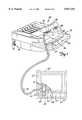
- FIG. 1is a perspective view of an automated external defibrillator (AED) with a pair of electrodes according to the present invention attached thereto.
- AEDautomated external defibrillator
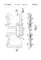
- FIG. 2is a detailed plan view of unpackaged electrodes positioned on release liners.
- FIG. 3is a cross-sectional view through the pair of electrodes of FIG. 2 taken along line 3--3.
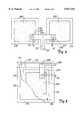
- FIG. 4is detailed plan view of unpackaged electrodes in accordance with a second embodiment of the present invention.
- FIG. 5is a plan view of the electrodes of FIG. 4 folded one on top of the other and provided within a package shown partially broken away.
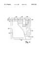
- FIG. 6is a detailed plan view of a pair of unpackaged electrodes in accordance with yet another embodiment of the present invention.
- FIG. 7is a plan view of the electrodes of FIG. 6 folded together and provided within a package shown partially broken away.
- FIG. 8is a block diagram of an electrical system of an AED.
- the present inventionis a circuit detectable arrangement of medical electrodes and a package therefore.
- the present inventionwill be described and illustrated as being connected to an automated external defibrillator (AED) but it should be understood that the present invention is equally applicable to numerous other devices utilizing packaged electrodes.
- AEDautomated external defibrillator
- FIG. 1illustrates a pair of electrodes 50 connected to an AED 22.
- defibrillator 22includes a plastic case 24 with a carrying handle 26 on the top portion.
- An illuminable rescue switch 28, visual maintenance indicator 30, data communication port 32 and charging port 34are located on the outside of case 24 for easy access by an operator.
- Case 24also includes an electrode compartment 36 which is enclosed by a lid 38 which is mounted to the case by hinges (not shown).
- a friction-type releasable latch including pinsholds lid 38 closed when defibrillator 22 is not in use. Finger-receiving recess 31 in lid 28 is grasped to open the lid and access the electrode compartment 26.
- the diagnostic display panelincludes a visual "Call for Service” indicator light, a “Check Electrode” indicator light, a “Check 9 Volt Battery” indicator light, a “Check 12 Volt Battery” indicator light and a "Power” indicator light.
- Defibrillator electrodes 50each include a polymer backing layer 52, and a patient-engaging layer 54 of conductive adhesive which overlays the backing layer.
- backing layer 52is a flexible polymeric foam.
- Conductive adhesives for electrode useare well-known and commercially available, such as Ludlou Technical Products' conductive hydrogel.
- a current-dispersing flexible conductive sheet(not shown) is preferably located between backing layer 52 and patient-engaging layer 54 so as to disperse current over conductive adhesive layer 54.
- the conductive sheetneed not be the same size as the electrode and is preferably a homogeneous, solid, thinly deposited metallic substance, or a conductive ink. Meshes or patterns of conductive adhesives or inks may be used.
- Insulated lead wires 56extend from each electrode 50, and have a first end connected within each electrode 50 to its conductive sheet and a second end connected to a connector 58.
- Connector 58is configured to releasably mate with electrode connector 40 in electrode compartment 30, as illustrated. Electrodes 50 are sealed within a polymer or polymer-metal laminate package 60. Lead wires 56 and connector 58 extend from package 60.
- FIGS. 2 and 3A first embodiment of a pair of electrodes 50 to be provided within package 60 is shown in FIGS. 2 and 3.
- the package design of FIG. 1illustrates electrodes 50 folded against one another and provided within package 60.
- each electrode 50includes backing layer 52, patient-engaging layer 54 of conductive adhesive, a conductive sheet 53 (illustrated in FIG. 3) between layers 52 and 54, and a liner 61.
- Liner 61can comprise any conventional lining material such as plastic sheeting or treated papers. Both electrodes 50 may be provided together on a single liner sheet; however, for reasons set out below, other compensations would be necessary.
- a lead wire 56connects with each electrode 50. Specifically, lead wire 56 extends partially within each electrode 50, preferably between backing layer 52 and conductive adhesive layer 54.
- a terminal 62is provided at the end of lead wire 56 within each electrode 50 for preferably connecting the conductive wire of lead wire 56 to conductive sheet 53. Otherwise, terminal 62 may directly conduct current to conductive adhesive layer 54.
- each terminal 62preferably extends through backing layer 52 so as to provide a conductor 63 at the surface of backing layer 52.
- Conductors 63are connected together electrically by a flexible conductive connector 64.
- Conductive connector 64preferably comprises a metal foil or a fine wire which can be folded for packaging and easily torn or broken, the reasons for which will be evident from the description below.
- connector 64can be conventionally electrically connected to conductors 63 by conductive adhesive, heat bonding solder, or the like.
- conductors 63 and conductive connector 64are positioned and arranged, such as that illustrated in FIG.
- Electrodes 50when electrodes 50 are to be packaged within package 60, they can be folded against one another by a fold line 65 bisecting conductive connector 64.
- an electrical circuitcan be completed between lead wires 56 through terminals 62, conductors 63, and connecting conductor 64.
- a strip of tear resistant material 66that is more preferably provided at about the mid-point of conductor connector 64 and which extends transverse to the direction of connector 64. Tear resistance strip 66 may comprise a plastic, paper or other non-conductive material which is tear resistant as compared to the material of conductive connector 64.
- electrodes 50are folded toward one another along fold line 65 and positioned within a pouch type package 60 that can be conventionally made either of two sheets connected together or a single sheet folded and sealed at its edges 67.
- One of sealed edges 67accommodates the passage of lead wires 56 from package 60 by forming a small opening through the edge.
- edge 67also accommodates passage of a portion of tear resistant strip 66 from the interior of package 60 to the outside of package 60.
- a tear line 69is also provided along package 60 dividing interior portion 68 of package 60 from the rest of the inside of the package that is inhabited by the folded pair of electrodes. Tear line 69 may be facilitated by a line of weakening or other means for controlling package opening along tear line 69.
- Conductive connector 64preferably extends within package 60 sufficiently from each electrode 50 into package interior portion 68 so that tear resistant strip also lies completely within interior portion 68.
- tear resistant strip 66extending from package 60 can be used for grabbing by the user to open the package. Otherwise, the user would simply rip along tear line 69. In tearing open package 60 along tear line 69, conductive connector 64 will be likewise torn or broken. Thus, by opening package 60, the circuit between lead wires 56 of electrodes 50 within package 60 will be broken.
- the provision of tear resistant strip 66not only provides an extension for grabbing to begin opening package 60, it also ensures that conductive connector 64 will be broken during a tearing operation. As a result of this construction, the presence of an unbroken conductive connector 64 and the subsequent breaking thereof during usage of electrodes 50 can be automatically detected for determining the presence or absence of fresh electrodes 50.
- each electrode 200is preferably the same as that described above including a backing layer, a patient-engaging conductive adhesive layer, and a current dispersing flexible conducting sheet therebetween.
- lead wires 56extend partially within electrodes 200 between the backing layer and the conductive adhesive layer of each electrode 200 and are preferably connected with the conductive sheets at terminals 202.
- Terminals 202similarly provide conductors 204 at the surface of the backing layers of each electrode 200.
- Electrodes 200are each provided on separate liners 206. As with the previous embodiment, a single liner could be used.
- a pair of electrodes 200are connected together by a conductive connector 208 specifically connected from one conductor 204 of one electrode 200 to conductor 204 of another electrode 200.
- conductor 204can be conventionally connected to conductive connector 208 by conductive adhesive, heat bonding, solder or the like.
- Conductive connector 208preferably comprises a thin metal foil.
- conductor connector 208includes an extension portion 209 that is preferably integrally formed with conductive connector 208. Portion 209 extends transversely from conductive connector 208 preferably at about center fold line 210, and extends substantially further than the edge of liners 206.
- Electrodes 200are received within an electrode interior portion 216 which is divided from an interior portion 218 by a tear line 220. As above, lead wires 56 are accommodated through one of edge seals 214. Likewise, portion 209 of conductive connector 208 preferably extends sufficiently that it extends through the same edge seal to facilitate opening of the package. Conductive connector 208 preferably extends within the package sufficiently from each electrode 200 into package interior portion 218 so that portion 209 of conductive connector 208 lies within in interior package portion 218.
- Extension portion 209ensures that tearing along tear line 220 by grasping extension point 209 will tear through conductive connector 208 and break the circuit between lead wires 56.
- defibrillator 22As described generally below, for determining the presence of fresh electrodes 200.
- Electrodes 300are provided which are similarly constructed as the aforementioned embodiments, including a backing layer, a conductive adhesive layer and a conductive sheet therebetween.
- Lead wires 56are preferably connected with the conductive sheets between the backing layer and the conductive adhesive layer by terminals 302.
- Each terminal 302also preferably provides a conductor 304 at the surface of the backing layer of each electrode 300.
- a pair of electrodes 300are connected together by a conductive connector 306, specifically connected at each end to a conductor 304 of a terminal 302.
- conventional connection meanscan be used, such as conductive adhesives, heat bonding, solder or the like.
- Conductive connector 306may comprise a thin foil, a fine wire, or the like, but preferably comprises a thin foil. Each electrode 300 is also preferably provided on a separate liner 308. A fold line 310 substantially bisects the conductive connector 306 so that electrodes 300 can be folded back to back with liners 308 against one another. Conductive connector 306 completes an electrical circuit for connecting lead wires 56 by way of terminals 302 and conductors 304.
- Electrodes 300are positioned within an electrode receiving space 312 of package 314 which may be conventionally constructed with sealed edges 316.
- the interior of the packageis divided by a tear line 318 into electrode receiving portion 312 and an interior portion 320.
- conductive connector 306forms a loop that extends within interior portion 320 of package 314.
- both of lead wires 56pass through the loop defined by conductive connector 306 when the electrodes are positioned back to back as folded along fold line 310.
- lead wires 56pass between conductive connector 306 and an edge of a liner 308.
- conductive connector 306is sufficiently long so that when the electrodes are folded back to back, conductive connector 306 forms the loop so as to facilitate both lead wires 56 within interior portion 320.
- package 314can be easily opened along tear line 318 by a user grasping lead wires 56 where they exit package 314 at edge seal 316. Then, tearing the package open along tear line 318 will also tear or break conductive connector 306.
- Lead wires 56in this case, act as a tear strip facilitating easy opening of package 314. This construction is advantageous in that in a single action opens the electrode package, breaks the electrical circuit, and removes the electrodes from the package. As above, the function of making and breaking the electrical circuit completed by connector 306 between lead wires 56 can be monitored, as set out below, for determining the presence of fresh electrodes 300.
- liners 61, 206 and 308could instead comprise a single liner to which both electrodes 50, 200, and 300 respectively, are adhered. To do this, the liners would also be folded to position the electrodes within the respective packages. However, in order to provide that conductive connectors, 64, 208, and 306, respectively, extend across tear lines 69, 220 and 318, respectively, the conductive connectors must be of sufficiently greater length than the distance between the electrodes on the single liner so that when the single liners are folded, the conductive connectors will form a loop that extends sufficiently away from the folded edge of the single liner. It should be noted that the present invention is equally applicable to solid liners and to liners having a plurality of perforations formed therein.
- FIG. 8is a block diagram of electrical system 70 of defibrillator 10.
- the overall operation of defibrillator 10is controlled by a digital microprocessor-based control system 72 which includes a processor 74 interfaced to program memory 76, data memory 77, event memory 78 and real time clock 79.
- the operating program executed by processor 74is stored in program memory 76.
- Electrical poweris provided by a rechargeable twelve volt lead-acid cartridge battery 80 and a nine volt battery 82 which are removably positioned within the battery compartment and connected to power generation circuit 84.
- Charging port 25is coupled to power generation circuit 84, enabling twelve volt battery 80 to be connected to a twelve volt vehicle battery (not shown) or a 120VAC charger (also not shown) and recharged while mounted within defibrillator 22.
- battery 80can be removed from defibrillator 22 and charged in a stand-alone charger (not shown).
- Power generation circuit 84is also connected to power control circuit 88 and processor 74.
- Power control circuit 88is connected to lid switch 90, watch dog timer 92, real time clock 79 and processor 74.
- Lid switch 90is a magnetic read relay switch in one embodiment, and provides signals to processor 74 indicating whether lid 38 is open or closed.
- Data communication port 32is coupled to processor 74 for two-way serial data transfer using an RS-232 protocol.
- Rescue switch 28, maintenance indicator 30, the rescue switch light, resume switch, indicator lights of the diagnostic display panel, the voice circuit 94 and piezoelectric audible alarm 96are also connected to processor 74.
- Voice circuit 94is connected to speaker 41. In response to voice prompt control signals from processor 74, circuit 94 and speaker 41 generate audible voice prompts.
- High voltage generation circuit 86is also connected to and controlled by processor 74. Circuits such as 86 are generally known, and disclosed, for example, in the commonly assigned Persson et al. U.S. Pat. No. 5,405,361, which is hereby incorporated by reference. In response to charge control signals provided by processor 74, high voltage generation circuit 86 is operated in a charge mode during which one set of semiconductor switches (not separately shown) cause a plurality of capacitors (also not shown), to be charged in parallel to the 12V potential supplied by power generation circuit 84.
- high voltage generation circuit 86is operated in a discharge mode during which the capacitors are discharged in series by another set of semiconductor switches (not separately shown) to produce the high voltage defibrillation pulses.
- the defibrillation pulsesare applied to the patient through electrode connector 40 which is connected to the high voltage generation circuit 86.
- Impedance measuring circuit 100is connected to electrode connector 40 and real time clock 79, and is interfaced to processor 74 through analog-to-digital (A/D) converter 102. Impedance measuring circuit 100 receives a clock signal having a predetermined magnitude from clock 79, and applies the signal to electrodes 50, for example, through connector 40. The magnitude of the clock signal received back from electrodes 50 through connector 40 is monitored by impedance measuring circuit 100. An impedance signal representative of the impedance present across electrode connector 40 is then generated by circuit 100 as a function of the ratio of the magnitudes of the applied and received clock signals (i.e., the attenuation of the applied signal).
- a relatively low resistancee.g., less than about 10 ohms
- a relatively high resistancee.g., greater than about two hundred fifty ohms
- the resistance across connector 40will be between about twenty-five and two hundred ohms when fresh electrodes 50 are properly positioned on the patient with good electrical contacts. It should be noted that these resistance values are given as exemplary ranges and are not meant to be absolute ranges.
- the impedance signal representative of the impedance measured by circuit 100is digitized by A/D converter 102 and provided to processor 74.
Landscapes
- Health & Medical Sciences (AREA)
- Engineering & Computer Science (AREA)
- Biomedical Technology (AREA)
- Nuclear Medicine, Radiotherapy & Molecular Imaging (AREA)
- Radiology & Medical Imaging (AREA)
- Life Sciences & Earth Sciences (AREA)
- Animal Behavior & Ethology (AREA)
- General Health & Medical Sciences (AREA)
- Public Health (AREA)
- Veterinary Medicine (AREA)
- Cardiology (AREA)
- Heart & Thoracic Surgery (AREA)
- Electrotherapy Devices (AREA)
Abstract
Description
Claims (28)
Priority Applications (6)
| Application Number | Priority Date | Filing Date | Title |
|---|---|---|---|
| US08/658,200US5817151A (en) | 1996-06-04 | 1996-06-04 | Circuit detectable packaged medical electrodes |
| US08/668,117US5700281A (en) | 1996-06-04 | 1996-06-17 | Stage and state monitoring automated external defibrillator |
| PCT/US1997/007899WO1997043000A1 (en) | 1996-05-10 | 1997-05-08 | Defibrillator electrode circuitry |
| EP97925505AEP0956089A4 (en) | 1996-05-10 | 1997-05-08 | Defibrillator electrode circuitry |
| AU30625/97AAU3062597A (en) | 1996-05-10 | 1997-05-08 | Defibrillator electrode circuitry |
| US09/121,079US6101413A (en) | 1996-06-04 | 1998-07-21 | Circuit detectable pediatric defibrillation electrodes |
Applications Claiming Priority (1)
| Application Number | Priority Date | Filing Date | Title |
|---|---|---|---|
| US08/658,200US5817151A (en) | 1996-06-04 | 1996-06-04 | Circuit detectable packaged medical electrodes |
Related Child Applications (2)
| Application Number | Title | Priority Date | Filing Date |
|---|---|---|---|
| US08/668,117Continuation-In-PartUS5700281A (en) | 1996-05-10 | 1996-06-17 | Stage and state monitoring automated external defibrillator |
| US09/121,079Continuation-In-PartUS6101413A (en) | 1996-06-04 | 1998-07-21 | Circuit detectable pediatric defibrillation electrodes |
Publications (1)
| Publication Number | Publication Date |
|---|---|
| US5817151Atrue US5817151A (en) | 1998-10-06 |
Family
ID=24640311
Family Applications (1)
| Application Number | Title | Priority Date | Filing Date |
|---|---|---|---|
| US08/658,200Expired - LifetimeUS5817151A (en) | 1996-05-10 | 1996-06-04 | Circuit detectable packaged medical electrodes |
Country Status (1)
| Country | Link |
|---|---|
| US (1) | US5817151A (en) |
Cited By (100)
| Publication number | Priority date | Publication date | Assignee | Title |
|---|---|---|---|---|
| US6115638A (en)* | 1998-05-04 | 2000-09-05 | Survivalink Corporation | Medical electrode with conductive release liner |
| US6292697B1 (en) | 2000-02-15 | 2001-09-18 | Medtronic, Inc. | Testing sterile packaged components of an implantable medical device prior to chronic implantation |
| US20030083729A1 (en)* | 2001-10-31 | 2003-05-01 | Thomas Solosko | Single separable electrode and self-contained pad viability tester |
| US6577102B1 (en) | 2001-09-21 | 2003-06-10 | Defibtech Llc | Medical device battery system including a secondary power supply |
| US20030195567A1 (en)* | 2002-04-10 | 2003-10-16 | Medtronic Physio-Control Corp. | Automated external defibrillator with user interface for adult and pediatric applications |
| US6694193B2 (en) | 2001-09-14 | 2004-02-17 | Koninklijke Philips Electronics N.V. | Medical electrode and release liner configurations facilitating packaged electrode characterization |
| DE10255919A1 (en)* | 2002-11-29 | 2004-06-17 | Corscience Gmbh & Co.Kg | Electrode unit for emergency heart stimulation combines two gel electrodes with separation wall in single ready to use unit |
| DE10261601B3 (en)* | 2002-12-20 | 2004-07-01 | Metrax Gmbh | pad package |
| USD498848S1 (en) | 2003-10-01 | 2004-11-23 | Defibtech, Llc | Pads for an automatic external defibrillator |
| US20050075671A1 (en)* | 2003-10-02 | 2005-04-07 | Vaisnys Gintaras A. | External defibrillator enclosure with accessory storage slot |
| US20050077078A1 (en)* | 2003-10-08 | 2005-04-14 | Holmes Benjamin J. | Tear resistant flexible substrate |
| US6912425B2 (en) | 2002-03-08 | 2005-06-28 | Medtronic Physio-Control Manufacturing Corp. | Therapy and monitoring electrodes with patient accommodating features and electrode sensing |
| US6955864B1 (en) | 2001-09-21 | 2005-10-18 | Defibtech, Llc | Medical device battery pack with active status indication |
| US6965799B2 (en) | 2002-03-08 | 2005-11-15 | Medtronic Physio-Control Manufacturing Corp. | Therapy and monitoring electrodes with patient accommodating features |
| USD514951S1 (en) | 2003-10-01 | 2006-02-14 | Defibtech, Llc | Packaging for pads for an automatic external defibrillator |
| DE102004056341A1 (en)* | 2004-11-22 | 2006-05-24 | Weinmann Geräte für Medizin GmbH + Co. KG | Electrode for defibrillator, has carrier with metallic contact unit and adhesive layer, and protective film in area of adhesive layer before use of electrode, where carrier extends into edge area unadhered with film |
| US7069074B2 (en) | 2001-11-07 | 2006-06-27 | Medtronic Emergency Response Systems, Inc. | Easy-to-use electrode and package |
| US20060142806A1 (en)* | 2004-12-27 | 2006-06-29 | Koninklijke Philips Electronics N.V. | Method and article for storing an automatic external defibrillator for use without a prescription |
| US20060259080A1 (en)* | 2005-03-21 | 2006-11-16 | Defibtech, Llc | System and method for presenting defibrillator status information while in standby mode |
| US20070044809A1 (en)* | 2005-08-29 | 2007-03-01 | Dawn Flynn | Disposable sheath for telementry leads of a monitoring device |
| US20070203558A1 (en)* | 2004-03-23 | 2007-08-30 | Koninklijke Phillips Electronics N.V. | Self-Storing Medical Electrodes |
| US20070255382A1 (en)* | 2006-04-27 | 2007-11-01 | Peter Meyer | Electrode pad packaging systems and methods |
| US20080136652A1 (en)* | 2006-03-21 | 2008-06-12 | Defibtech, Llc | System and Method for Effectively Indicating Element Failure or a Preventive Maintenance Condition in an Automatic External Defibrillator (AED) |
| USRE40471E1 (en) | 1998-10-29 | 2008-08-26 | Cardiac Science, Inc. | AED with force sensor |
| US7548781B2 (en) | 2005-03-21 | 2009-06-16 | Defibtech, Llc | Environmentally responsive active status indicator system and method |
| US20090187225A1 (en)* | 2005-03-21 | 2009-07-23 | Defibtech, Llc | PCB blade connector system and method |
| EP2105162A2 (en) | 2008-03-26 | 2009-09-30 | Cardiac Science Corporation | Method and apparatus for defrosting a defibrillation electrode |
| US7930023B2 (en) | 2001-09-21 | 2011-04-19 | Defibtech, Llc | Automatic external defibrillator with active status indicator |
| USD637298S1 (en) | 2008-11-13 | 2011-05-03 | Defibtech, Llc | Packaging for pads for an automated external defibrillator |
| USD675739S1 (en) | 2011-12-07 | 2013-02-05 | Cardiac Science Corporation | Automated external defibrillator electrode pad |
| US8428751B2 (en) | 2010-03-18 | 2013-04-23 | Covidien Lp | Electrode delivery system |
| US8613708B2 (en) | 2010-10-08 | 2013-12-24 | Cardiac Science Corporation | Ambulatory electrocardiographic monitor with jumpered sensing electrode |
| US8613709B2 (en) | 2010-10-08 | 2013-12-24 | Cardiac Science Corporation | Ambulatory electrocardiographic monitor for providing ease of use in women |
| US8626277B2 (en) | 2010-10-08 | 2014-01-07 | Cardiac Science Corporation | Computer-implemented electrocardiographic data processor with time stamp correlation |
| USD717955S1 (en) | 2013-11-07 | 2014-11-18 | Bardy Diagnostics, Inc. | Electrocardiography monitor |
| US8996138B2 (en) | 2006-07-05 | 2015-03-31 | Zoll Medical Corporation | Breakaway electrical connections for defibrillation electrode package |
| US9037477B2 (en) | 2010-10-08 | 2015-05-19 | Cardiac Science Corporation | Computer-implemented system and method for evaluating ambulatory electrocardiographic monitoring of cardiac rhythm disorders |
| US9072885B2 (en) | 2012-09-27 | 2015-07-07 | Covidien Lp | Systems for hydrating defibrillation electrodes |
| US9091718B2 (en) | 2011-09-15 | 2015-07-28 | Zoll Medical Corporation | Testing electrical connections between cardiac resuscitation devices and external electrodes |
| US9126055B2 (en) | 2012-04-20 | 2015-09-08 | Cardiac Science Corporation | AED faster time to shock method and device |
| USD744659S1 (en) | 2013-11-07 | 2015-12-01 | Bardy Diagnostics, Inc. | Extended wear electrode patch |
| US9345414B1 (en) | 2013-09-25 | 2016-05-24 | Bardy Diagnostics, Inc. | Method for providing dynamic gain over electrocardiographic data with the aid of a digital computer |
| US9364155B2 (en) | 2013-09-25 | 2016-06-14 | Bardy Diagnostics, Inc. | Self-contained personal air flow sensing monitor |
| WO2016092800A1 (en)* | 2014-12-09 | 2016-06-16 | Nihon Kohden Corporation | Defibrillation pad |
| US9408545B2 (en) | 2013-09-25 | 2016-08-09 | Bardy Diagnostics, Inc. | Method for efficiently encoding and compressing ECG data optimized for use in an ambulatory ECG monitor |
| US9408551B2 (en) | 2013-11-14 | 2016-08-09 | Bardy Diagnostics, Inc. | System and method for facilitating diagnosis of cardiac rhythm disorders with the aid of a digital computer |
| US9433380B1 (en) | 2013-09-25 | 2016-09-06 | Bardy Diagnostics, Inc. | Extended wear electrocardiography patch |
| US9433367B2 (en) | 2013-09-25 | 2016-09-06 | Bardy Diagnostics, Inc. | Remote interfacing of extended wear electrocardiography and physiological sensor monitor |
| USD766447S1 (en) | 2015-09-10 | 2016-09-13 | Bardy Diagnostics, Inc. | Extended wear electrode patch |
| US9504423B1 (en) | 2015-10-05 | 2016-11-29 | Bardy Diagnostics, Inc. | Method for addressing medical conditions through a wearable health monitor with the aid of a digital computer |
| US9545204B2 (en) | 2013-09-25 | 2017-01-17 | Bardy Diagnostics, Inc. | Extended wear electrocardiography patch |
| US20170080211A1 (en)* | 2015-09-23 | 2017-03-23 | Grahame Michael David Walling | Electrode array packaging system |
| US9619660B1 (en) | 2013-09-25 | 2017-04-11 | Bardy Diagnostics, Inc. | Computer-implemented system for secure physiological data collection and processing |
| US9615763B2 (en) | 2013-09-25 | 2017-04-11 | Bardy Diagnostics, Inc. | Ambulatory electrocardiography monitor recorder optimized for capturing low amplitude cardiac action potential propagation |
| US9655537B2 (en) | 2013-09-25 | 2017-05-23 | Bardy Diagnostics, Inc. | Wearable electrocardiography and physiology monitoring ensemble |
| US9655538B2 (en) | 2013-09-25 | 2017-05-23 | Bardy Diagnostics, Inc. | Self-authenticating electrocardiography monitoring circuit |
| US9700227B2 (en) | 2013-09-25 | 2017-07-11 | Bardy Diagnostics, Inc. | Ambulatory electrocardiography monitoring patch optimized for capturing low amplitude cardiac action potential propagation |
| US9717432B2 (en) | 2013-09-25 | 2017-08-01 | Bardy Diagnostics, Inc. | Extended wear electrocardiography patch using interlaced wire electrodes |
| USD793566S1 (en) | 2015-09-10 | 2017-08-01 | Bardy Diagnostics, Inc. | Extended wear electrode patch |
| US9717433B2 (en) | 2013-09-25 | 2017-08-01 | Bardy Diagnostics, Inc. | Ambulatory electrocardiography monitoring patch optimized for capturing low amplitude cardiac action potential propagation |
| US9737224B2 (en) | 2013-09-25 | 2017-08-22 | Bardy Diagnostics, Inc. | Event alerting through actigraphy embedded within electrocardiographic data |
| US9775536B2 (en) | 2013-09-25 | 2017-10-03 | Bardy Diagnostics, Inc. | Method for constructing a stress-pliant physiological electrode assembly |
| USD801528S1 (en) | 2013-11-07 | 2017-10-31 | Bardy Diagnostics, Inc. | Electrocardiography monitor |
| USD831833S1 (en) | 2013-11-07 | 2018-10-23 | Bardy Diagnostics, Inc. | Extended wear electrode patch |
| US10165946B2 (en) | 2013-09-25 | 2019-01-01 | Bardy Diagnostics, Inc. | Computer-implemented system and method for providing a personal mobile device-triggered medical intervention |
| CN109475746A (en)* | 2017-06-20 | 2019-03-15 | 伊罗·特波 | Portable Disposable Automated External Defibrillator Device |
| US10251576B2 (en) | 2013-09-25 | 2019-04-09 | Bardy Diagnostics, Inc. | System and method for ECG data classification for use in facilitating diagnosis of cardiac rhythm disorders with the aid of a digital computer |
| US10433748B2 (en) | 2013-09-25 | 2019-10-08 | Bardy Diagnostics, Inc. | Extended wear electrocardiography and physiological sensor monitor |
| US10433751B2 (en) | 2013-09-25 | 2019-10-08 | Bardy Diagnostics, Inc. | System and method for facilitating a cardiac rhythm disorder diagnosis based on subcutaneous cardiac monitoring data |
| US10463269B2 (en) | 2013-09-25 | 2019-11-05 | Bardy Diagnostics, Inc. | System and method for machine-learning-based atrial fibrillation detection |
| US10624551B2 (en) | 2013-09-25 | 2020-04-21 | Bardy Diagnostics, Inc. | Insertable cardiac monitor for use in performing long term electrocardiographic monitoring |
| US10667711B1 (en) | 2013-09-25 | 2020-06-02 | Bardy Diagnostics, Inc. | Contact-activated extended wear electrocardiography and physiological sensor monitor recorder |
| USD892340S1 (en) | 2013-11-07 | 2020-08-04 | Bardy Diagnostics, Inc. | Extended wear electrode patch |
| US10736531B2 (en) | 2013-09-25 | 2020-08-11 | Bardy Diagnostics, Inc. | Subcutaneous insertable cardiac monitor optimized for long term, low amplitude electrocardiographic data collection |
| US10736529B2 (en) | 2013-09-25 | 2020-08-11 | Bardy Diagnostics, Inc. | Subcutaneous insertable electrocardiography monitor |
| US10799137B2 (en) | 2013-09-25 | 2020-10-13 | Bardy Diagnostics, Inc. | System and method for facilitating a cardiac rhythm disorder diagnosis with the aid of a digital computer |
| US10806360B2 (en) | 2013-09-25 | 2020-10-20 | Bardy Diagnostics, Inc. | Extended wear ambulatory electrocardiography and physiological sensor monitor |
| US10820801B2 (en) | 2013-09-25 | 2020-11-03 | Bardy Diagnostics, Inc. | Electrocardiography monitor configured for self-optimizing ECG data compression |
| US10888239B2 (en) | 2013-09-25 | 2021-01-12 | Bardy Diagnostics, Inc. | Remote interfacing electrocardiography patch |
| US20210213296A1 (en)* | 2015-08-26 | 2021-07-15 | Element Science, Inc. | Wearable devices |
| USD926323S1 (en) | 2020-03-30 | 2021-07-27 | Zoll Medical Corporation | Automated external defibrillator electrode pad |
| US11096579B2 (en) | 2019-07-03 | 2021-08-24 | Bardy Diagnostics, Inc. | System and method for remote ECG data streaming in real-time |
| US11103718B2 (en) | 2016-12-19 | 2021-08-31 | Hearthero, Inc. | Automated external defibrillator device and methods of use |
| US11116451B2 (en) | 2019-07-03 | 2021-09-14 | Bardy Diagnostics, Inc. | Subcutaneous P-wave centric insertable cardiac monitor with energy harvesting capabilities |
| US11213237B2 (en) | 2013-09-25 | 2022-01-04 | Bardy Diagnostics, Inc. | System and method for secure cloud-based physiological data processing and delivery |
| USD942013S1 (en) | 2019-10-23 | 2022-01-25 | Cellaed Life Saver Pty Ltd | Defibrillator case |
| US11324441B2 (en) | 2013-09-25 | 2022-05-10 | Bardy Diagnostics, Inc. | Electrocardiography and respiratory monitor |
| USD959668S1 (en) | 2020-08-31 | 2022-08-02 | Cellaed Life Saver Pty Ltd | Defibrillator |
| US11524168B2 (en) | 2016-12-19 | 2022-12-13 | Hearthero, Inc. | Self-contained, connected automated external defibrillator systems and methods of use |
| USD972730S1 (en) | 2020-08-31 | 2022-12-13 | Cellaed Life Saver Pty Ltd | Defibrillator |
| US11529526B1 (en) | 2021-12-10 | 2022-12-20 | Hearthero, Inc. | Automated external defibrillator |
| USD974563S1 (en) | 2019-11-04 | 2023-01-03 | Cellaed Life Saver Pty Ltd | Defibrillator |
| US11678830B2 (en) | 2017-12-05 | 2023-06-20 | Bardy Diagnostics, Inc. | Noise-separating cardiac monitor |
| US11696681B2 (en) | 2019-07-03 | 2023-07-11 | Bardy Diagnostics Inc. | Configurable hardware platform for physiological monitoring of a living body |
| US11723575B2 (en) | 2013-09-25 | 2023-08-15 | Bardy Diagnostics, Inc. | Electrocardiography patch |
| US11883676B2 (en) | 2020-10-14 | 2024-01-30 | Hearthero, Inc. | Automated external defibrillator systems with operation adjustment features according to temperature and methods of use |
| US11975209B2 (en) | 2014-02-24 | 2024-05-07 | Element Science, Inc. | External defibrillator |
| US12186573B2 (en) | 2018-10-10 | 2025-01-07 | Element Science, Inc. | Wearable medical device with disposable and reusable components |
| USD1084345S1 (en) | 2022-07-28 | 2025-07-15 | Zoll Medical Corporation | Chest compression sensor |
| USD1084346S1 (en) | 2022-07-28 | 2025-07-15 | Zoll Medical Corporation | Chest compression sensor |
Citations (13)
| Publication number | Priority date | Publication date | Assignee | Title |
|---|---|---|---|---|
| US3685645A (en)* | 1970-08-17 | 1972-08-22 | Physio Control Corp | Defibrillation electrode pad and package therefor |
| US4423732A (en)* | 1980-09-26 | 1984-01-03 | Cordis Corporation | Sterile connector system for packaged pacer |
| US4494552A (en)* | 1980-08-08 | 1985-01-22 | R2 Corporation | Physiological monitoring electrode system |
| US4543958A (en)* | 1979-04-30 | 1985-10-01 | Ndm Corporation | Medical electrode assembly |
| US4777954A (en)* | 1986-06-30 | 1988-10-18 | Nepera Inc. | Conductive adhesive medical electrode assemblies |
| US5255677A (en)* | 1991-02-26 | 1993-10-26 | Vickers Plc | Disposable electrodes for electromyography (EMG) and nerve conduction velocity (NCV) and kit containing same |
| US5354321A (en)* | 1990-10-10 | 1994-10-11 | Mario Berger | Patch arrangement for galvanic treatment |
| US5366497A (en)* | 1992-03-31 | 1994-11-22 | Cardiotronics, Inc. | Non-invasive, radiolucent cardiac electrode |
| WO1994026350A1 (en)* | 1993-05-18 | 1994-11-24 | Heartstream, Inc. | Defibrillator electrode system |
| US5402884A (en)* | 1992-09-24 | 1995-04-04 | Surviva Link Corporation | Medical electrode packaging technology |
| US5462157A (en)* | 1993-10-28 | 1995-10-31 | Zmd Corporation | Electrode package |
| US5466217A (en)* | 1992-06-02 | 1995-11-14 | Alza Corporation | Iontophoretic drug delivery apparatus |
| US5562710A (en)* | 1993-04-06 | 1996-10-08 | Hewlett-Packard Company | Defibrillator patient connection system with automatic identification |
- 1996
- 1996-06-04USUS08/658,200patent/US5817151A/ennot_activeExpired - Lifetime
Patent Citations (13)
| Publication number | Priority date | Publication date | Assignee | Title |
|---|---|---|---|---|
| US3685645A (en)* | 1970-08-17 | 1972-08-22 | Physio Control Corp | Defibrillation electrode pad and package therefor |
| US4543958A (en)* | 1979-04-30 | 1985-10-01 | Ndm Corporation | Medical electrode assembly |
| US4494552A (en)* | 1980-08-08 | 1985-01-22 | R2 Corporation | Physiological monitoring electrode system |
| US4423732A (en)* | 1980-09-26 | 1984-01-03 | Cordis Corporation | Sterile connector system for packaged pacer |
| US4777954A (en)* | 1986-06-30 | 1988-10-18 | Nepera Inc. | Conductive adhesive medical electrode assemblies |
| US5354321A (en)* | 1990-10-10 | 1994-10-11 | Mario Berger | Patch arrangement for galvanic treatment |
| US5255677A (en)* | 1991-02-26 | 1993-10-26 | Vickers Plc | Disposable electrodes for electromyography (EMG) and nerve conduction velocity (NCV) and kit containing same |
| US5366497A (en)* | 1992-03-31 | 1994-11-22 | Cardiotronics, Inc. | Non-invasive, radiolucent cardiac electrode |
| US5466217A (en)* | 1992-06-02 | 1995-11-14 | Alza Corporation | Iontophoretic drug delivery apparatus |
| US5402884A (en)* | 1992-09-24 | 1995-04-04 | Surviva Link Corporation | Medical electrode packaging technology |
| US5562710A (en)* | 1993-04-06 | 1996-10-08 | Hewlett-Packard Company | Defibrillator patient connection system with automatic identification |
| WO1994026350A1 (en)* | 1993-05-18 | 1994-11-24 | Heartstream, Inc. | Defibrillator electrode system |
| US5462157A (en)* | 1993-10-28 | 1995-10-31 | Zmd Corporation | Electrode package |
Cited By (246)
| Publication number | Priority date | Publication date | Assignee | Title |
|---|---|---|---|---|
| US6115638A (en)* | 1998-05-04 | 2000-09-05 | Survivalink Corporation | Medical electrode with conductive release liner |
| USRE40471E1 (en) | 1998-10-29 | 2008-08-26 | Cardiac Science, Inc. | AED with force sensor |
| US6292697B1 (en) | 2000-02-15 | 2001-09-18 | Medtronic, Inc. | Testing sterile packaged components of an implantable medical device prior to chronic implantation |
| US6694193B2 (en) | 2001-09-14 | 2004-02-17 | Koninklijke Philips Electronics N.V. | Medical electrode and release liner configurations facilitating packaged electrode characterization |
| USRE43050E1 (en) | 2001-09-14 | 2011-12-27 | Koninklijke Philips Electronics N.V. | Medical electrode and release liner configurations facilitating packaged electrode characterization |
| US8224441B2 (en) | 2001-09-21 | 2012-07-17 | Defibtech, Llc | Automatic external defibrillator with active status indicator |
| US20100075208A1 (en)* | 2001-09-21 | 2010-03-25 | Defibtech, Llc | Medical Device Battery Pack with Active Status Indication |
| US7855010B2 (en) | 2001-09-21 | 2010-12-21 | Defibtech Llc | Medical device battery pack |
| US7930023B2 (en) | 2001-09-21 | 2011-04-19 | Defibtech, Llc | Automatic external defibrillator with active status indicator |
| US7625662B2 (en) | 2001-09-21 | 2009-12-01 | Defibtech, Llc | Medical device battery back system and method for providing active status indication |
| US7495413B2 (en) | 2001-09-21 | 2009-02-24 | Defibtech Llc | Medical device battery system including a secondary power supply |
| US8498701B2 (en) | 2001-09-21 | 2013-07-30 | Defibtech, LLP | Automatic external defibrillator with active status indicator |
| US20110190838A1 (en)* | 2001-09-21 | 2011-08-04 | Defibtech, Llc | Automatic External Defibrillator with Active Status Indicator |
| US6955864B1 (en) | 2001-09-21 | 2005-10-18 | Defibtech, Llc | Medical device battery pack with active status indication |
| US20110190839A1 (en)* | 2001-09-21 | 2011-08-04 | Defibtech, Llc | Automatic External Defibrillator with Active Status Indicator |
| US20110190837A1 (en)* | 2001-09-21 | 2011-08-04 | Defibtech, Llc | Automatic External Defibrillator with Active Status Indicator |
| US20050256546A1 (en)* | 2001-09-21 | 2005-11-17 | Vaisnys Gintaras A | Medical device battery pack with active status indication |
| US8343644B2 (en) | 2001-09-21 | 2013-01-01 | Defibtech, Llc | Medical device with a multiple function battery status indicator |
| US6577102B1 (en) | 2001-09-21 | 2003-06-10 | Defibtech Llc | Medical device battery system including a secondary power supply |
| US8494628B2 (en) | 2001-09-21 | 2013-07-23 | Defibtech, Llc | Automatic external defibrillator with active status indicator |
| US20060206152A1 (en)* | 2001-10-02 | 2006-09-14 | Medtronic Emergency Response Systems, Inc. | Easy-to-use electrode and package |
| US7797044B2 (en) | 2001-10-02 | 2010-09-14 | Physio-Control, Inc. | Easy-to-use electrode and package |
| US20100063558A9 (en)* | 2001-10-02 | 2010-03-11 | Medtronic Emergency Response Systems, Inc. | Easy-to-use electrode and package |
| US20070090355A1 (en)* | 2001-10-31 | 2007-04-26 | Koninklijke Philips Electronics, N.V. | Single separable electrode and self-contained pad viability tester |
| US7139615B2 (en)* | 2001-10-31 | 2006-11-21 | Koninklijke Philips Electronics, N.V. | Single separable electrode and self-contained pad viability tester |
| WO2003037176A3 (en)* | 2001-10-31 | 2003-12-04 | Koninkl Philips Electronics Nv | Single separable electrode and self-contained pad viability tester |
| US20030083729A1 (en)* | 2001-10-31 | 2003-05-01 | Thomas Solosko | Single separable electrode and self-contained pad viability tester |
| US7069074B2 (en) | 2001-11-07 | 2006-06-27 | Medtronic Emergency Response Systems, Inc. | Easy-to-use electrode and package |
| US6965799B2 (en) | 2002-03-08 | 2005-11-15 | Medtronic Physio-Control Manufacturing Corp. | Therapy and monitoring electrodes with patient accommodating features |
| US6912425B2 (en) | 2002-03-08 | 2005-06-28 | Medtronic Physio-Control Manufacturing Corp. | Therapy and monitoring electrodes with patient accommodating features and electrode sensing |
| US20030195567A1 (en)* | 2002-04-10 | 2003-10-16 | Medtronic Physio-Control Corp. | Automated external defibrillator with user interface for adult and pediatric applications |
| US6990373B2 (en) | 2002-04-10 | 2006-01-24 | Medtronic Emergency Response Systems, Inc. | Automated external defibrillator with user interface for adult and pediatric applications |
| DE10255919A1 (en)* | 2002-11-29 | 2004-06-17 | Corscience Gmbh & Co.Kg | Electrode unit for emergency heart stimulation combines two gel electrodes with separation wall in single ready to use unit |
| US20050244709A1 (en)* | 2002-12-20 | 2005-11-03 | Jurgen Bucher | Electrode pack |
| DE10261601B3 (en)* | 2002-12-20 | 2004-07-01 | Metrax Gmbh | pad package |
| USD498848S1 (en) | 2003-10-01 | 2004-11-23 | Defibtech, Llc | Pads for an automatic external defibrillator |
| USD514951S1 (en) | 2003-10-01 | 2006-02-14 | Defibtech, Llc | Packaging for pads for an automatic external defibrillator |
| US8014859B2 (en)* | 2003-10-02 | 2011-09-06 | Defibtech, Llc | External defibrillator enclosure with accessory storage slot |
| US20050075671A1 (en)* | 2003-10-02 | 2005-04-07 | Vaisnys Gintaras A. | External defibrillator enclosure with accessory storage slot |
| US7071419B2 (en)* | 2003-10-08 | 2006-07-04 | Motorola, Inc. | Tear resistant flexible substrate |
| US20050077078A1 (en)* | 2003-10-08 | 2005-04-14 | Holmes Benjamin J. | Tear resistant flexible substrate |
| US7822488B2 (en)* | 2004-03-23 | 2010-10-26 | Koninklijke Philips Electronics N.V. | Self-storing medical electrodes |
| US20070203558A1 (en)* | 2004-03-23 | 2007-08-30 | Koninklijke Phillips Electronics N.V. | Self-Storing Medical Electrodes |
| DE102004056341A1 (en)* | 2004-11-22 | 2006-05-24 | Weinmann Geräte für Medizin GmbH + Co. KG | Electrode for defibrillator, has carrier with metallic contact unit and adhesive layer, and protective film in area of adhesive layer before use of electrode, where carrier extends into edge area unadhered with film |
| US20060142806A1 (en)* | 2004-12-27 | 2006-06-29 | Koninklijke Philips Electronics N.V. | Method and article for storing an automatic external defibrillator for use without a prescription |
| US20080288011A1 (en)* | 2004-12-27 | 2008-11-20 | Koninklijke Philips Electronics, N.V. | Method and Article for Storing an Automatic External Defibrillator for Use Without a Prescription |
| US20090187225A1 (en)* | 2005-03-21 | 2009-07-23 | Defibtech, Llc | PCB blade connector system and method |
| US7627372B2 (en) | 2005-03-21 | 2009-12-01 | Defibtech, Llc | System and method for presenting defibrillator status information while in standby mode |
| US20100168811A1 (en)* | 2005-03-21 | 2010-07-01 | Defibtech, Llc | Identifying the Usage Status of a Defibrillation Pad Assembly |
| US20110213262A1 (en)* | 2005-03-21 | 2011-09-01 | Defibtech, Llc | Method for Presenting Current and Stored ECG Waveforms on a Portable, External Defibrillator |
| US20100069981A1 (en)* | 2005-03-21 | 2010-03-18 | Defibtech, Llc | System and Method for Presenting Defibrillator Status Information While in Standby Mode |
| US7912543B2 (en) | 2005-03-21 | 2011-03-22 | Defibtech, Llc | PCB blade connector system and method |
| US20090233458A1 (en)* | 2005-03-21 | 2009-09-17 | Defibtech, Llc | PCB blade connector system and method |
| US7548781B2 (en) | 2005-03-21 | 2009-06-16 | Defibtech, Llc | Environmentally responsive active status indicator system and method |
| US8280506B2 (en) | 2005-03-21 | 2012-10-02 | Defibtech, Llc | PCB blade connector system and method |
| US7953478B2 (en) | 2005-03-21 | 2011-05-31 | Defibtech, Llc | System and method for presenting defibrillator status information while in standby mode |
| US20060259080A1 (en)* | 2005-03-21 | 2006-11-16 | Defibtech, Llc | System and method for presenting defibrillator status information while in standby mode |
| US8185196B2 (en) | 2005-03-21 | 2012-05-22 | Defibtech, Llc | PCB blade connector system and method |
| US8185197B2 (en) | 2005-03-21 | 2012-05-22 | Defibtech, Llc | Identifying the usage status of a defibrillation pad assembly |
| US8774916B2 (en) | 2005-03-21 | 2014-07-08 | Defibtech, Llc | PCB blade connector system and method |
| US8155755B2 (en)* | 2005-08-29 | 2012-04-10 | Dignity Health | Disposable sheath for telementry leads of a monitoring device |
| US20070044809A1 (en)* | 2005-08-29 | 2007-03-01 | Dawn Flynn | Disposable sheath for telementry leads of a monitoring device |
| US20110213433A1 (en)* | 2006-03-21 | 2011-09-01 | Defibtech, Llc | System and Method for Effectively Indicating Element Failure or a Preventive Maintenance Condition in an Automatic External Defibrillator (AED) |
| US8116863B2 (en) | 2006-03-21 | 2012-02-14 | Defibtech, Llc | System and method for effectively indicating element failure or a preventive maintenance condition in an automatic external defibrillator (AED) |
| US20080136652A1 (en)* | 2006-03-21 | 2008-06-12 | Defibtech, Llc | System and Method for Effectively Indicating Element Failure or a Preventive Maintenance Condition in an Automatic External Defibrillator (AED) |
| US8386035B2 (en) | 2006-03-21 | 2013-02-26 | Defibtech, Llc | System and method for effectively indicating element failure or a preventive maintenance condition in an automatic external defibrillator (AED) |
| US8260438B2 (en) | 2006-04-27 | 2012-09-04 | Tyco Healthcare Group Lp | Electrode pad packaging systems and methods |
| US20070255382A1 (en)* | 2006-04-27 | 2007-11-01 | Peter Meyer | Electrode pad packaging systems and methods |
| US20070255380A1 (en)* | 2006-04-27 | 2007-11-01 | Peter Meyer | Electrode pad packaging systems and methods |
| US9026230B2 (en) | 2006-04-27 | 2015-05-05 | Covidien Lp | Electrode pad packaging systems and methods |
| US20070255381A1 (en)* | 2006-04-27 | 2007-11-01 | Peter Meyer | Electrode pad packaging systems and methods |
| US8594812B2 (en) | 2006-04-27 | 2013-11-26 | Covidien Lp | Electrode pad packaging systems and methods |
| US8996138B2 (en) | 2006-07-05 | 2015-03-31 | Zoll Medical Corporation | Breakaway electrical connections for defibrillation electrode package |
| US20110106192A1 (en)* | 2008-03-26 | 2011-05-05 | Nassif Rabih C | Method and apparatus for defrosting a defibrillation electrode |
| US20090248128A1 (en)* | 2008-03-26 | 2009-10-01 | Cardiac Science Corporation | Method and apparatus for defrosting a defibrillation electrode |
| US7881785B2 (en) | 2008-03-26 | 2011-02-01 | Cardiac Science Corporation | Method and apparatus for defrosting a defibrillation electrode |
| EP2105162A2 (en) | 2008-03-26 | 2009-09-30 | Cardiac Science Corporation | Method and apparatus for defrosting a defibrillation electrode |
| US8260414B2 (en) | 2008-03-26 | 2012-09-04 | Cardiac Science Corporation | Method and apparatus for defrosting a defibrillation electrode |
| USD637298S1 (en) | 2008-11-13 | 2011-05-03 | Defibtech, Llc | Packaging for pads for an automated external defibrillator |
| US8428751B2 (en) | 2010-03-18 | 2013-04-23 | Covidien Lp | Electrode delivery system |
| US8942830B2 (en) | 2010-03-18 | 2015-01-27 | Covidien Lp | Electrode delivery system |
| US8613708B2 (en) | 2010-10-08 | 2013-12-24 | Cardiac Science Corporation | Ambulatory electrocardiographic monitor with jumpered sensing electrode |
| US8938287B2 (en) | 2010-10-08 | 2015-01-20 | Cardiac Science Corporation | Computer-implemented electrocardiograhic data processor with time stamp correlation |
| US8626277B2 (en) | 2010-10-08 | 2014-01-07 | Cardiac Science Corporation | Computer-implemented electrocardiographic data processor with time stamp correlation |
| US8613709B2 (en) | 2010-10-08 | 2013-12-24 | Cardiac Science Corporation | Ambulatory electrocardiographic monitor for providing ease of use in women |
| US9037477B2 (en) | 2010-10-08 | 2015-05-19 | Cardiac Science Corporation | Computer-implemented system and method for evaluating ambulatory electrocardiographic monitoring of cardiac rhythm disorders |
| US9091718B2 (en) | 2011-09-15 | 2015-07-28 | Zoll Medical Corporation | Testing electrical connections between cardiac resuscitation devices and external electrodes |
| USD675739S1 (en) | 2011-12-07 | 2013-02-05 | Cardiac Science Corporation | Automated external defibrillator electrode pad |
| US9126055B2 (en) | 2012-04-20 | 2015-09-08 | Cardiac Science Corporation | AED faster time to shock method and device |
| US9861807B2 (en) | 2012-09-27 | 2018-01-09 | Kpr U.S., Llc | System for hydrating defibrillation electrodes |
| US9072885B2 (en) | 2012-09-27 | 2015-07-07 | Covidien Lp | Systems for hydrating defibrillation electrodes |
| US9820665B2 (en) | 2013-09-25 | 2017-11-21 | Bardy Diagnostics, Inc. | Remote interfacing of extended wear electrocardiography and physiological sensor monitor |
| US10736531B2 (en) | 2013-09-25 | 2020-08-11 | Bardy Diagnostics, Inc. | Subcutaneous insertable cardiac monitor optimized for long term, low amplitude electrocardiographic data collection |
| US9364155B2 (en) | 2013-09-25 | 2016-06-14 | Bardy Diagnostics, Inc. | Self-contained personal air flow sensing monitor |
| US12369828B1 (en) | 2013-09-25 | 2025-07-29 | Bardy Diagnostics, Inc. | Extended wear ambulatory electrocardiogramay monitor |
| US12324672B1 (en) | 2013-09-25 | 2025-06-10 | Bardy Diagnostics, Inc. | Moisture-resistant electrocardiography monitor |
| US9408545B2 (en) | 2013-09-25 | 2016-08-09 | Bardy Diagnostics, Inc. | Method for efficiently encoding and compressing ECG data optimized for use in an ambulatory ECG monitor |
| US12310735B2 (en) | 2013-09-25 | 2025-05-27 | Bardy Diagnostics, Inc. | Extended wear ambulatory electrocardiography monitor |
| US9433380B1 (en) | 2013-09-25 | 2016-09-06 | Bardy Diagnostics, Inc. | Extended wear electrocardiography patch |
| US9433367B2 (en) | 2013-09-25 | 2016-09-06 | Bardy Diagnostics, Inc. | Remote interfacing of extended wear electrocardiography and physiological sensor monitor |
| US12303278B1 (en) | 2013-09-25 | 2025-05-20 | Bardy Diagnostics, Inc. | Electrocardiography patch |
| US11918364B2 (en) | 2013-09-25 | 2024-03-05 | Bardy Diagnostics, Inc. | Extended wear ambulatory electrocardiography and physiological sensor monitor |
| US9545228B2 (en) | 2013-09-25 | 2017-01-17 | Bardy Diagnostics, Inc. | Extended wear electrocardiography and respiration-monitoring patch |
| US9545204B2 (en) | 2013-09-25 | 2017-01-17 | Bardy Diagnostics, Inc. | Extended wear electrocardiography patch |
| US9554715B2 (en) | 2013-09-25 | 2017-01-31 | Bardy Diagnostics, Inc. | System and method for electrocardiographic data signal gain determination with the aid of a digital computer |
| US11826151B2 (en) | 2013-09-25 | 2023-11-28 | Bardy Diagnostics, Inc. | System and method for physiological data classification for use in facilitating diagnosis |
| US9619660B1 (en) | 2013-09-25 | 2017-04-11 | Bardy Diagnostics, Inc. | Computer-implemented system for secure physiological data collection and processing |
| US9615763B2 (en) | 2013-09-25 | 2017-04-11 | Bardy Diagnostics, Inc. | Ambulatory electrocardiography monitor recorder optimized for capturing low amplitude cardiac action potential propagation |
| US9642537B2 (en) | 2013-09-25 | 2017-05-09 | Bardy Diagnostics, Inc. | Ambulatory extended-wear electrocardiography and syncope sensor monitor |
| US9655537B2 (en) | 2013-09-25 | 2017-05-23 | Bardy Diagnostics, Inc. | Wearable electrocardiography and physiology monitoring ensemble |
| US9655538B2 (en) | 2013-09-25 | 2017-05-23 | Bardy Diagnostics, Inc. | Self-authenticating electrocardiography monitoring circuit |
| US9700227B2 (en) | 2013-09-25 | 2017-07-11 | Bardy Diagnostics, Inc. | Ambulatory electrocardiography monitoring patch optimized for capturing low amplitude cardiac action potential propagation |
| US9717432B2 (en) | 2013-09-25 | 2017-08-01 | Bardy Diagnostics, Inc. | Extended wear electrocardiography patch using interlaced wire electrodes |
| US11786159B2 (en) | 2013-09-25 | 2023-10-17 | Bardy Diagnostics, Inc. | Self-authenticating electrocardiography and physiological sensor monitor |
| US9717433B2 (en) | 2013-09-25 | 2017-08-01 | Bardy Diagnostics, Inc. | Ambulatory electrocardiography monitoring patch optimized for capturing low amplitude cardiac action potential propagation |
| US9730593B2 (en) | 2013-09-25 | 2017-08-15 | Bardy Diagnostics, Inc. | Extended wear ambulatory electrocardiography and physiological sensor monitor |
| US9730641B2 (en) | 2013-09-25 | 2017-08-15 | Bardy Diagnostics, Inc. | Monitor recorder-implemented method for electrocardiography value encoding and compression |
| US9737224B2 (en) | 2013-09-25 | 2017-08-22 | Bardy Diagnostics, Inc. | Event alerting through actigraphy embedded within electrocardiographic data |
| US9737211B2 (en) | 2013-09-25 | 2017-08-22 | Bardy Diagnostics, Inc. | Ambulatory rescalable encoding monitor recorder |
| US9775536B2 (en) | 2013-09-25 | 2017-10-03 | Bardy Diagnostics, Inc. | Method for constructing a stress-pliant physiological electrode assembly |
| US11744513B2 (en) | 2013-09-25 | 2023-09-05 | Bardy Diagnostics, Inc. | Electrocardiography and respiratory monitor |
| US11723575B2 (en) | 2013-09-25 | 2023-08-15 | Bardy Diagnostics, Inc. | Electrocardiography patch |
| US11701045B2 (en) | 2013-09-25 | 2023-07-18 | Bardy Diagnostics, Inc. | Expended wear ambulatory electrocardiography monitor |
| US11678799B2 (en) | 2013-09-25 | 2023-06-20 | Bardy Diagnostics, Inc. | Subcutaneous electrocardiography monitor configured for test-based data compression |
| US9901274B2 (en) | 2013-09-25 | 2018-02-27 | Bardy Diagnostics, Inc. | Electrocardiography patch |
| US11678832B2 (en) | 2013-09-25 | 2023-06-20 | Bardy Diagnostics, Inc. | System and method for atrial fibrillation detection in non-noise ECG data with the aid of a digital computer |
| US9955911B2 (en) | 2013-09-25 | 2018-05-01 | Bardy Diagnostics, Inc. | Electrocardiography and respiratory monitor recorder |
| US9955888B2 (en) | 2013-09-25 | 2018-05-01 | Bardy Diagnostics, Inc. | Ambulatory electrocardiography monitor recorder optimized for internal signal processing |
| US9955885B2 (en) | 2013-09-25 | 2018-05-01 | Bardy Diagnostics, Inc. | System and method for physiological data processing and delivery |
| US10004415B2 (en) | 2013-09-25 | 2018-06-26 | Bardy Diagnostics, Inc. | Extended wear electrocardiography patch |
| US10045709B2 (en) | 2013-09-25 | 2018-08-14 | Bardy Diagnostics, Inc. | System and method for facilitating a cardiac rhythm disorder diagnosis with the aid of a digital computer |
| US10052022B2 (en) | 2013-09-25 | 2018-08-21 | Bardy Diagnostics, Inc. | System and method for providing dynamic gain over non-noise electrocardiographic data with the aid of a digital computer |
| US11660037B2 (en) | 2013-09-25 | 2023-05-30 | Bardy Diagnostics, Inc. | System for electrocardiographic signal acquisition and processing |
| US10111601B2 (en) | 2013-09-25 | 2018-10-30 | Bardy Diagnostics, Inc. | Extended wear electrocardiography monitor optimized for capturing low amplitude cardiac action potential propagation |
| US11660035B2 (en) | 2013-09-25 | 2023-05-30 | Bardy Diagnostics, Inc. | Insertable cardiac monitor |
| US10154793B2 (en) | 2013-09-25 | 2018-12-18 | Bardy Diagnostics, Inc. | Extended wear electrocardiography patch with wire contact surfaces |
| US10165946B2 (en) | 2013-09-25 | 2019-01-01 | Bardy Diagnostics, Inc. | Computer-implemented system and method for providing a personal mobile device-triggered medical intervention |
| US10172534B2 (en) | 2013-09-25 | 2019-01-08 | Bardy Diagnostics, Inc. | Remote interfacing electrocardiography patch |
| US11653869B2 (en) | 2013-09-25 | 2023-05-23 | Bardy Diagnostics, Inc. | Multicomponent electrocardiography monitor |
| US11653870B2 (en) | 2013-09-25 | 2023-05-23 | Bardy Diagnostics, Inc. | System and method for display of subcutaneous cardiac monitoring data |
| US11653868B2 (en) | 2013-09-25 | 2023-05-23 | Bardy Diagnostics, Inc. | Subcutaneous insertable cardiac monitor optimized for electrocardiographic (ECG) signal acquisition |
| US10251576B2 (en) | 2013-09-25 | 2019-04-09 | Bardy Diagnostics, Inc. | System and method for ECG data classification for use in facilitating diagnosis of cardiac rhythm disorders with the aid of a digital computer |
| US10251575B2 (en) | 2013-09-25 | 2019-04-09 | Bardy Diagnostics, Inc. | Wearable electrocardiography and physiology monitoring ensemble |
| US10264992B2 (en) | 2013-09-25 | 2019-04-23 | Bardy Diagnostics, Inc. | Extended wear sewn electrode electrocardiography monitor |
| US10265015B2 (en) | 2013-09-25 | 2019-04-23 | Bardy Diagnostics, Inc. | Monitor recorder optimized for electrocardiography and respiratory data acquisition and processing |
| US10271756B2 (en) | 2013-09-25 | 2019-04-30 | Bardy Diagnostics, Inc. | Monitor recorder optimized for electrocardiographic signal processing |
| US10271755B2 (en) | 2013-09-25 | 2019-04-30 | Bardy Diagnostics, Inc. | Method for constructing physiological electrode assembly with sewn wire interconnects |
| US10278603B2 (en) | 2013-09-25 | 2019-05-07 | Bardy Diagnostics, Inc. | System and method for secure physiological data acquisition and storage |
| US10278606B2 (en) | 2013-09-25 | 2019-05-07 | Bardy Diagnostics, Inc. | Ambulatory electrocardiography monitor optimized for capturing low amplitude cardiac action potential propagation |
| US11647941B2 (en) | 2013-09-25 | 2023-05-16 | Bardy Diagnostics, Inc. | System and method for facilitating a cardiac rhythm disorder diagnosis with the aid of a digital computer |
| US10398334B2 (en) | 2013-09-25 | 2019-09-03 | Bardy Diagnostics, Inc. | Self-authenticating electrocardiography monitoring circuit |
| US10413205B2 (en) | 2013-09-25 | 2019-09-17 | Bardy Diagnostics, Inc. | Electrocardiography and actigraphy monitoring system |
| US10433748B2 (en) | 2013-09-25 | 2019-10-08 | Bardy Diagnostics, Inc. | Extended wear electrocardiography and physiological sensor monitor |
| US10433751B2 (en) | 2013-09-25 | 2019-10-08 | Bardy Diagnostics, Inc. | System and method for facilitating a cardiac rhythm disorder diagnosis based on subcutaneous cardiac monitoring data |
| US10433743B1 (en) | 2013-09-25 | 2019-10-08 | Bardy Diagnostics, Inc. | Method for secure physiological data acquisition and storage |
| US11647939B2 (en) | 2013-09-25 | 2023-05-16 | Bardy Diagnostics, Inc. | System and method for facilitating a cardiac rhythm disorder diagnosis with the aid of a digital computer |
| US10463269B2 (en) | 2013-09-25 | 2019-11-05 | Bardy Diagnostics, Inc. | System and method for machine-learning-based atrial fibrillation detection |
| US10478083B2 (en) | 2013-09-25 | 2019-11-19 | Bardy Diagnostics, Inc. | Extended wear ambulatory electrocardiography and physiological sensor monitor |
| US10499812B2 (en) | 2013-09-25 | 2019-12-10 | Bardy Diagnostics, Inc. | System and method for applying a uniform dynamic gain over cardiac data with the aid of a digital computer |
| US10561328B2 (en) | 2013-09-25 | 2020-02-18 | Bardy Diagnostics, Inc. | Multipart electrocardiography monitor optimized for capturing low amplitude cardiac action potential propagation |
| US10561326B2 (en) | 2013-09-25 | 2020-02-18 | Bardy Diagnostics, Inc. | Monitor recorder optimized for electrocardiographic potential processing |
| US10602977B2 (en) | 2013-09-25 | 2020-03-31 | Bardy Diagnostics, Inc. | Electrocardiography and respiratory monitor |
| US10624551B2 (en) | 2013-09-25 | 2020-04-21 | Bardy Diagnostics, Inc. | Insertable cardiac monitor for use in performing long term electrocardiographic monitoring |
| US10624552B2 (en) | 2013-09-25 | 2020-04-21 | Bardy Diagnostics, Inc. | Method for constructing physiological electrode assembly with integrated flexile wire components |
| US10631748B2 (en) | 2013-09-25 | 2020-04-28 | Bardy Diagnostics, Inc. | Extended wear electrocardiography patch with wire interconnects |
| US10667711B1 (en) | 2013-09-25 | 2020-06-02 | Bardy Diagnostics, Inc. | Contact-activated extended wear electrocardiography and physiological sensor monitor recorder |
| US10716516B2 (en) | 2013-09-25 | 2020-07-21 | Bardy Diagnostics, Inc. | Monitor recorder-implemented method for electrocardiography data compression |
| US11457852B2 (en) | 2013-09-25 | 2022-10-04 | Bardy Diagnostics, Inc. | Multipart electrocardiography monitor |
| US10736532B2 (en) | 2013-09-25 | 2020-08-11 | Bardy Diagnotics, Inc. | System and method for facilitating a cardiac rhythm disorder diagnosis with the aid of a digital computer |
| US9345414B1 (en) | 2013-09-25 | 2016-05-24 | Bardy Diagnostics, Inc. | Method for providing dynamic gain over electrocardiographic data with the aid of a digital computer |
| US10736529B2 (en) | 2013-09-25 | 2020-08-11 | Bardy Diagnostics, Inc. | Subcutaneous insertable electrocardiography monitor |
| US11445907B2 (en) | 2013-09-25 | 2022-09-20 | Bardy Diagnostics, Inc. | Ambulatory encoding monitor recorder optimized for rescalable encoding and method of use |
| US11445961B2 (en) | 2013-09-25 | 2022-09-20 | Bardy Diagnostics, Inc. | Self-authenticating electrocardiography and physiological sensor monitor |
| US10799137B2 (en) | 2013-09-25 | 2020-10-13 | Bardy Diagnostics, Inc. | System and method for facilitating a cardiac rhythm disorder diagnosis with the aid of a digital computer |
| US10806360B2 (en) | 2013-09-25 | 2020-10-20 | Bardy Diagnostics, Inc. | Extended wear ambulatory electrocardiography and physiological sensor monitor |
| US10813568B2 (en) | 2013-09-25 | 2020-10-27 | Bardy Diagnostics, Inc. | System and method for classifier-based atrial fibrillation detection with the aid of a digital computer |
| US10813567B2 (en) | 2013-09-25 | 2020-10-27 | Bardy Diagnostics, Inc. | System and method for composite display of subcutaneous cardiac monitoring data |
| US10820801B2 (en) | 2013-09-25 | 2020-11-03 | Bardy Diagnostics, Inc. | Electrocardiography monitor configured for self-optimizing ECG data compression |
| US10849523B2 (en) | 2013-09-25 | 2020-12-01 | Bardy Diagnostics, Inc. | System and method for ECG data classification for use in facilitating diagnosis of cardiac rhythm disorders |
| US11445969B2 (en) | 2013-09-25 | 2022-09-20 | Bardy Diagnostics, Inc. | System and method for event-centered display of subcutaneous cardiac monitoring data |
| US11445970B2 (en) | 2013-09-25 | 2022-09-20 | Bardy Diagnostics, Inc. | System and method for neural-network-based atrial fibrillation detection with the aid of a digital computer |
| US10888239B2 (en) | 2013-09-25 | 2021-01-12 | Bardy Diagnostics, Inc. | Remote interfacing electrocardiography patch |
| US10939841B2 (en) | 2013-09-25 | 2021-03-09 | Bardy Diagnostics, Inc. | Wearable electrocardiography and physiology monitoring ensemble |
| US11006883B2 (en) | 2013-09-25 | 2021-05-18 | Bardy Diagnostics, Inc. | Extended wear electrocardiography and physiological sensor monitor |
| US11013446B2 (en) | 2013-09-25 | 2021-05-25 | Bardy Diagnostics, Inc. | System for secure physiological data acquisition and delivery |
| US11051743B2 (en) | 2013-09-25 | 2021-07-06 | Bardy Diagnostics, Inc. | Electrocardiography patch |
| US11051754B2 (en) | 2013-09-25 | 2021-07-06 | Bardy Diagnostics, Inc. | Electrocardiography and respiratory monitor |
| US11445964B2 (en) | 2013-09-25 | 2022-09-20 | Bardy Diagnostics, Inc. | System for electrocardiographic potentials processing and acquisition |
| US11445967B2 (en) | 2013-09-25 | 2022-09-20 | Bardy Diagnostics, Inc. | Electrocardiography patch |
| US11445965B2 (en) | 2013-09-25 | 2022-09-20 | Bardy Diagnostics, Inc. | Subcutaneous insertable cardiac monitor optimized for long-term electrocardiographic monitoring |
| US11445908B2 (en) | 2013-09-25 | 2022-09-20 | Bardy Diagnostics, Inc. | Subcutaneous electrocardiography monitor configured for self-optimizing ECG data compression |
| US11445966B2 (en) | 2013-09-25 | 2022-09-20 | Bardy Diagnostics, Inc. | Extended wear electrocardiography and physiological sensor monitor |
| US11179087B2 (en) | 2013-09-25 | 2021-11-23 | Bardy Diagnostics, Inc. | System for facilitating a cardiac rhythm disorder diagnosis with the aid of a digital computer |
| US11213237B2 (en) | 2013-09-25 | 2022-01-04 | Bardy Diagnostics, Inc. | System and method for secure cloud-based physiological data processing and delivery |
| US11445962B2 (en) | 2013-09-25 | 2022-09-20 | Bardy Diagnostics, Inc. | Ambulatory electrocardiography monitor |
| US11272872B2 (en) | 2013-09-25 | 2022-03-15 | Bardy Diagnostics, Inc. | Expended wear ambulatory electrocardiography and physiological sensor monitor |
| US11324441B2 (en) | 2013-09-25 | 2022-05-10 | Bardy Diagnostics, Inc. | Electrocardiography and respiratory monitor |
| USD801528S1 (en) | 2013-11-07 | 2017-10-31 | Bardy Diagnostics, Inc. | Electrocardiography monitor |
| USD831833S1 (en) | 2013-11-07 | 2018-10-23 | Bardy Diagnostics, Inc. | Extended wear electrode patch |
| USD717955S1 (en) | 2013-11-07 | 2014-11-18 | Bardy Diagnostics, Inc. | Electrocardiography monitor |
| USD838370S1 (en) | 2013-11-07 | 2019-01-15 | Bardy Diagnostics, Inc. | Electrocardiography monitor |
| USD744659S1 (en) | 2013-11-07 | 2015-12-01 | Bardy Diagnostics, Inc. | Extended wear electrode patch |
| USD892340S1 (en) | 2013-11-07 | 2020-08-04 | Bardy Diagnostics, Inc. | Extended wear electrode patch |
| US9408551B2 (en) | 2013-11-14 | 2016-08-09 | Bardy Diagnostics, Inc. | System and method for facilitating diagnosis of cardiac rhythm disorders with the aid of a digital computer |
| US12427329B2 (en) | 2014-02-24 | 2025-09-30 | Element Science, Inc. | External defibrillator |
| US11975209B2 (en) | 2014-02-24 | 2024-05-07 | Element Science, Inc. | External defibrillator |
| WO2016092800A1 (en)* | 2014-12-09 | 2016-06-16 | Nihon Kohden Corporation | Defibrillation pad |
| JP2016106914A (en)* | 2014-12-09 | 2016-06-20 | 日本光電工業株式会社 | Defibrillation pad |
| US10232166B2 (en)* | 2014-12-09 | 2019-03-19 | Nihon Kohden Corporation | Defibrillation pad |
| US20210213296A1 (en)* | 2015-08-26 | 2021-07-15 | Element Science, Inc. | Wearable devices |
| US11701521B2 (en)* | 2015-08-26 | 2023-07-18 | Element Science, Inc. | Wearable devices |
| US12350508B2 (en) | 2015-08-26 | 2025-07-08 | Element Science, Inc. | Wearable devices |
| USD793566S1 (en) | 2015-09-10 | 2017-08-01 | Bardy Diagnostics, Inc. | Extended wear electrode patch |
| USD766447S1 (en) | 2015-09-10 | 2016-09-13 | Bardy Diagnostics, Inc. | Extended wear electrode patch |
| US20170080211A1 (en)* | 2015-09-23 | 2017-03-23 | Grahame Michael David Walling | Electrode array packaging system |
| US11660445B2 (en)* | 2015-09-23 | 2023-05-30 | Cochlear Limited | Electrode array packaging system |
| US9788722B2 (en) | 2015-10-05 | 2017-10-17 | Bardy Diagnostics, Inc. | Method for addressing medical conditions through a wearable health monitor with the aid of a digital computer |
| US9504423B1 (en) | 2015-10-05 | 2016-11-29 | Bardy Diagnostics, Inc. | Method for addressing medical conditions through a wearable health monitor with the aid of a digital computer |
| US10390700B2 (en) | 2015-10-05 | 2019-08-27 | Bardy Diagnostics, Inc. | Health monitoring apparatus for initiating a treatment of a patient based on physiological data with the aid of a digital computer |
| US10869601B2 (en) | 2015-10-05 | 2020-12-22 | Bardy Diagnostics, Inc. | System and method for patient medical care initiation based on physiological monitoring data with the aid of a digital computer |
| US9936875B2 (en) | 2015-10-05 | 2018-04-10 | Bardy Diagnostics, Inc. | Health monitoring apparatus for initiating a treatment of a patient with the aid of a digital computer |
| US10123703B2 (en) | 2015-10-05 | 2018-11-13 | Bardy Diagnostics, Inc. | Health monitoring apparatus with wireless capabilities for initiating a patient treatment with the aid of a digital computer |
| US11524168B2 (en) | 2016-12-19 | 2022-12-13 | Hearthero, Inc. | Self-contained, connected automated external defibrillator systems and methods of use |
| US11103718B2 (en) | 2016-12-19 | 2021-08-31 | Hearthero, Inc. | Automated external defibrillator device and methods of use |
| US20200398066A1 (en)* | 2017-06-20 | 2020-12-24 | Cellaed Life Saver Pty Ltd | Portable single use automated external defibrillator device |
| CN109475746A (en)* | 2017-06-20 | 2019-03-15 | 伊罗·特波 | Portable Disposable Automated External Defibrillator Device |
| US20190329057A1 (en)* | 2017-06-20 | 2019-10-31 | Erol TEBER | A portable single use automated external defibrillator device |
| JP2020524058A (en)* | 2017-06-20 | 2020-08-13 | セルエーイーディー ライフ セーバー ピーティーワイ リミテッド | Portable single-use automatic external defibrillator |
| US10799709B2 (en)* | 2017-06-20 | 2020-10-13 | Cellaed Life Saver Pty Ltd | Portable single use automated external defibrillator device |
| US11678830B2 (en) | 2017-12-05 | 2023-06-20 | Bardy Diagnostics, Inc. | Noise-separating cardiac monitor |
| US12186573B2 (en) | 2018-10-10 | 2025-01-07 | Element Science, Inc. | Wearable medical device with disposable and reusable components |
| US11096579B2 (en) | 2019-07-03 | 2021-08-24 | Bardy Diagnostics, Inc. | System and method for remote ECG data streaming in real-time |
| US11696681B2 (en) | 2019-07-03 | 2023-07-11 | Bardy Diagnostics Inc. | Configurable hardware platform for physiological monitoring of a living body |
| US11116451B2 (en) | 2019-07-03 | 2021-09-14 | Bardy Diagnostics, Inc. | Subcutaneous P-wave centric insertable cardiac monitor with energy harvesting capabilities |
| US11678798B2 (en) | 2019-07-03 | 2023-06-20 | Bardy Diagnostics Inc. | System and method for remote ECG data streaming in real-time |
| US11653880B2 (en) | 2019-07-03 | 2023-05-23 | Bardy Diagnostics, Inc. | System for cardiac monitoring with energy-harvesting-enhanced data transfer capabilities |
| USD942013S1 (en) | 2019-10-23 | 2022-01-25 | Cellaed Life Saver Pty Ltd | Defibrillator case |
| USD974563S1 (en) | 2019-11-04 | 2023-01-03 | Cellaed Life Saver Pty Ltd | Defibrillator |
| USD926323S1 (en) | 2020-03-30 | 2021-07-27 | Zoll Medical Corporation | Automated external defibrillator electrode pad |
| USD1060681S1 (en) | 2020-08-31 | 2025-02-04 | Cellaed Life Saver Pty Ltd | Defibrillator |
| USD959668S1 (en) | 2020-08-31 | 2022-08-02 | Cellaed Life Saver Pty Ltd | Defibrillator |
| USD972730S1 (en) | 2020-08-31 | 2022-12-13 | Cellaed Life Saver Pty Ltd | Defibrillator |
| US11883676B2 (en) | 2020-10-14 | 2024-01-30 | Hearthero, Inc. | Automated external defibrillator systems with operation adjustment features according to temperature and methods of use |
| US11529526B1 (en) | 2021-12-10 | 2022-12-20 | Hearthero, Inc. | Automated external defibrillator |
| USD1084345S1 (en) | 2022-07-28 | 2025-07-15 | Zoll Medical Corporation | Chest compression sensor |
| USD1084346S1 (en) | 2022-07-28 | 2025-07-15 | Zoll Medical Corporation | Chest compression sensor |
Similar Documents
| Publication | Publication Date | Title |
|---|---|---|
| US5817151A (en) | Circuit detectable packaged medical electrodes | |
| US5700281A (en) | Stage and state monitoring automated external defibrillator | |
| US5697955A (en) | Defibrillator electrodes and date code detector circuit | |
| US6101413A (en) | Circuit detectable pediatric defibrillation electrodes | |
| EP0756878B1 (en) | Automated external defribillator | |
| US5797969A (en) | One button lid activated automatic external defibrillator | |
| US5617853A (en) | Defibrillator electrode system using a flexible substrate and having electrode test features | |
| US6125298A (en) | Defibrillation system for pediatric patients | |
| USRE40471E1 (en) | AED with force sensor | |
| US9002473B2 (en) | Electrode and enclosure for cardiac monitoring and treatment | |
| US6083246A (en) | Lid open detection circuit for automated external defibrillators | |
| CN101534899A (en) | Case for defibrillator electrode pads and release liner | |
| US7603173B2 (en) | Electrode package attached to exterior of defibrillator | |
| US5955956A (en) | Audible alarm system for an automated external defibrillator | |
| US8996138B2 (en) | Breakaway electrical connections for defibrillation electrode package | |
| US7590456B2 (en) | Triangular or crescent shaped defibrillation electrode | |
| EP0757912B1 (en) | Automated external defibrillator with self-test system | |
| CN101534900B (en) | Halibut release liner for a defibrillator electrode pad | |
| EP0956089A1 (en) | Defibrillator electrode circuitry | |
| EP2527001B1 (en) | Testing of defibrillator electrodes | |
| US20080009911A1 (en) | Condition sensor for medical device package | |
| EP1637181A1 (en) | Automated external defibrillator | |
| US20250195903A1 (en) | Defibrillator | |
| HK1067565A (en) | Automated external defibrillator |
Legal Events
| Date | Code | Title | Description |
|---|---|---|---|
| AS | Assignment | Owner name:SURVIVA LINK CORPORATION, MINNESOTA Free format text:ASSIGNMENT OF ASSIGNORS INTEREST;ASSIGNORS:OLSON, KENNETH F.;STOLTE, JOHN F.;UTKE, NORA J.;AND OTHERS;REEL/FRAME:008024/0201 Effective date:19960604 | |
| STCF | Information on status: patent grant | Free format text:PATENTED CASE | |
| FPAY | Fee payment | Year of fee payment:4 | |
| AS | Assignment | Owner name:HSBC BANK, USA, NEW YORK Free format text:SECURITY AGREEMENT;ASSIGNOR:CARDIAC SCIENCE, INC.;REEL/FRAME:013146/0001 Effective date:20020530 | |
| AS | Assignment | Owner name:CARDIAC SCIENCE, INC., MINNESOTA Free format text:ASSIGNMENT OF ASSIGNORS INTEREST;ASSIGNOR:SURVIVALINK CORPORATION;REEL/FRAME:013280/0068 Effective date:20020718 | |
| FEPP | Fee payment procedure | Free format text:PAT HOLDER NO LONGER CLAIMS SMALL ENTITY STATUS, ENTITY STATUS SET TO UNDISCOUNTED (ORIGINAL EVENT CODE: STOL); ENTITY STATUS OF PATENT OWNER: LARGE ENTITY | |
| REFU | Refund | Free format text:REFUND - PAYMENT OF MAINTENANCE FEE, 8TH YR, SMALL ENTITY (ORIGINAL EVENT CODE: R2552); ENTITY STATUS OF PATENT OWNER: LARGE ENTITY | |
| FPAY | Fee payment | Year of fee payment:8 | |
| FEPP | Fee payment procedure | Free format text:ENTITY STATUS SET TO UNDISCOUNTED (ORIGINAL EVENT CODE: BIG.); ENTITY STATUS OF PATENT OWNER: LARGE ENTITY | |
| AS | Assignment | Owner name:CARDIAC SCIENCE CORPORATION, WASHINGTON Free format text:MERGER;ASSIGNOR:CARDIAC SCIENCE, INC.;REEL/FRAME:018260/0675 Effective date:20060224 | |
| FPAY | Fee payment | Year of fee payment:12 | |
| AS | Assignment | Owner name:SILICON VALLEY BANK,CALIFORNIA Free format text:SECURITY AGREEMENT;ASSIGNOR:CARDIAC SCIENCE, INC.;REEL/FRAME:024492/0931 Effective date:20100607 Owner name:SILICON VALLEY BANK, CALIFORNIA Free format text:SECURITY AGREEMENT;ASSIGNOR:CARDIAC SCIENCE, INC.;REEL/FRAME:024492/0931 Effective date:20100607 | |
| AS | Assignment | Owner name:CARDIAC SCIENCE CORPORATION, WASHINGTON Free format text:RELEASE BY SECURED PARTY;ASSIGNOR:SILICON VALLEY BANK;REEL/FRAME:029389/0937 Effective date:20121012 | |
| AS | Assignment | Owner name:DBS BANK LTD., BANGALORE BRANCH, INDIA Free format text:SECURITY AGREEMENT;ASSIGNOR:CARDIAC SCIENCE CORPORATION;REEL/FRAME:029733/0340 Effective date:20121228 | |
| AS | Assignment | Owner name:CARD-SCI INC., CALIFORNIA Free format text:ASSIGNMENT OF ASSIGNORS INTEREST;ASSIGNOR:CARDIAC SCIENCE CORPORATION;REEL/FRAME:037627/0418 Effective date:20160125 | |
| AS | Assignment | Owner name:THE PRIVATEBANK AND TRUST COMPANY, ILLINOIS Free format text:SECURITY INTEREST;ASSIGNOR:CARD-SCI INC.;REEL/FRAME:037689/0592 Effective date:20160125 | |
| AS | Assignment | Owner name:CARD-SCI INC., CALIFORNIA Free format text:CORRECTIVE ASSIGNMENT TO CORRECT THE PATENT NO. 6143233 THAT WAS INCORRECTLY ASSIGNED PREVIOUSLY RECORDED ON REEL 037627 FRAME 0418. ASSIGNOR(S) HEREBY CONFIRMS THE THE CORRECT PATENT NUMBER IS 6148233;ASSIGNOR:CARDIAC SCIENCE CORPORATION;REEL/FRAME:037783/0215 Effective date:20160125 Owner name:CARDIAC SCIENCE CORPORATION, WISCONSIN Free format text:CHANGE OF NAME;ASSIGNOR:CARD-SCI INC.;REEL/FRAME:037793/0106 Effective date:20160126 | |
| AS | Assignment | Owner name:CARDIAC SCIENCE CORPORATION, WISCONSIN Free format text:CHANGE OF NAME;ASSIGNOR:CARD-SCI INC.;REEL/FRAME:037897/0952 Effective date:20160126 | |
| AS | Assignment | Owner name:CARDIAC SCIENCE CORPORATION, WISCONSIN Free format text:RELEASE BY SECURED PARTY;ASSIGNOR:CIBC BANK USA (FKA THE PRIVATEBANK AND TRUST COMPANY);REEL/FRAME:050300/0804 Effective date:20190826 | |
| AS | Assignment | Owner name:ZOLL MEDICAL CORPORATION, MASSACHUSETTS Free format text:ASSIGNMENT OF ASSIGNORS INTEREST;ASSIGNOR:CARDIAC SCIENCE CORPORATION;REEL/FRAME:056391/0439 Effective date:20210409 |