US5817034A - Apparatus and method for removing tissue - Google Patents
Apparatus and method for removing tissueDownload PDFInfo
- Publication number
- US5817034A US5817034AUS08/546,482US54648295AUS5817034AUS 5817034 AUS5817034 AUS 5817034AUS 54648295 AUS54648295 AUS 54648295AUS 5817034 AUS5817034 AUS 5817034A
- Authority
- US
- United States
- Prior art keywords
- elongated
- blunt obturator
- tissue
- obturator
- blunt
- Prior art date
- Legal status (The legal status is an assumption and is not a legal conclusion. Google has not performed a legal analysis and makes no representation as to the accuracy of the status listed.)
- Expired - Lifetime
Links
Images


Classifications
- A—HUMAN NECESSITIES
- A61—MEDICAL OR VETERINARY SCIENCE; HYGIENE
- A61B—DIAGNOSIS; SURGERY; IDENTIFICATION
- A61B10/00—Instruments for taking body samples for diagnostic purposes; Other methods or instruments for diagnosis, e.g. for vaccination diagnosis, sex determination or ovulation-period determination; Throat striking implements
- A61B10/02—Instruments for taking cell samples or for biopsy
- A61B10/0233—Pointed or sharp biopsy instruments
- A61B10/0266—Pointed or sharp biopsy instruments means for severing sample
- A—HUMAN NECESSITIES
- A61—MEDICAL OR VETERINARY SCIENCE; HYGIENE
- A61B—DIAGNOSIS; SURGERY; IDENTIFICATION
- A61B17/00—Surgical instruments, devices or methods
- A61B17/34—Trocars; Puncturing needles
- A—HUMAN NECESSITIES
- A61—MEDICAL OR VETERINARY SCIENCE; HYGIENE
- A61B—DIAGNOSIS; SURGERY; IDENTIFICATION
- A61B17/00—Surgical instruments, devices or methods
- A61B17/34—Trocars; Puncturing needles
- A61B17/3417—Details of tips or shafts, e.g. grooves, expandable, bendable; Multiple coaxial sliding cannulas, e.g. for dilating
- A—HUMAN NECESSITIES
- A61—MEDICAL OR VETERINARY SCIENCE; HYGIENE
- A61B—DIAGNOSIS; SURGERY; IDENTIFICATION
- A61B17/00—Surgical instruments, devices or methods
- A61B17/34—Trocars; Puncturing needles
- A61B17/3494—Trocars; Puncturing needles with safety means for protection against accidental cutting or pricking, e.g. limiting insertion depth, pressure sensors
- A61B17/3496—Protecting sleeves or inner probes; Retractable tips
- A—HUMAN NECESSITIES
- A61—MEDICAL OR VETERINARY SCIENCE; HYGIENE
- A61B—DIAGNOSIS; SURGERY; IDENTIFICATION
- A61B10/00—Instruments for taking body samples for diagnostic purposes; Other methods or instruments for diagnosis, e.g. for vaccination diagnosis, sex determination or ovulation-period determination; Throat striking implements
- A61B10/02—Instruments for taking cell samples or for biopsy
- A61B2010/0208—Biopsy devices with actuators, e.g. with triggered spring mechanisms
- A—HUMAN NECESSITIES
- A61—MEDICAL OR VETERINARY SCIENCE; HYGIENE
- A61B—DIAGNOSIS; SURGERY; IDENTIFICATION
- A61B17/00—Surgical instruments, devices or methods
- A61B2017/00743—Type of operation; Specification of treatment sites
- A61B2017/00796—Breast surgery
- A61B2017/008—Removal of tumors
- A—HUMAN NECESSITIES
- A61—MEDICAL OR VETERINARY SCIENCE; HYGIENE
- A61B—DIAGNOSIS; SURGERY; IDENTIFICATION
- A61B17/00—Surgical instruments, devices or methods
- A61B17/32—Surgical cutting instruments
- A61B17/320016—Endoscopic cutting instruments, e.g. arthroscopes, resectoscopes
- A61B17/32002—Endoscopic cutting instruments, e.g. arthroscopes, resectoscopes with continuously rotating, oscillating or reciprocating cutting instruments
- A61B2017/320024—Morcellators, e.g. having a hollow cutting tube with an annular cutter for morcellating and removing tissue
- A—HUMAN NECESSITIES
- A61—MEDICAL OR VETERINARY SCIENCE; HYGIENE
- A61B—DIAGNOSIS; SURGERY; IDENTIFICATION
- A61B17/00—Surgical instruments, devices or methods
- A61B17/32—Surgical cutting instruments
- A61B17/320016—Endoscopic cutting instruments, e.g. arthroscopes, resectoscopes
- A61B2017/32004—Endoscopic cutting instruments, e.g. arthroscopes, resectoscopes having a laterally movable cutting member at its most distal end which remains within the contours of said end
- A—HUMAN NECESSITIES
- A61—MEDICAL OR VETERINARY SCIENCE; HYGIENE
- A61B—DIAGNOSIS; SURGERY; IDENTIFICATION
- A61B17/00—Surgical instruments, devices or methods
- A61B17/32—Surgical cutting instruments
- A61B2017/320044—Blunt dissectors
Definitions
- the present disclosurerelates to apparatus and method for biopsy/removal of tissue from within a patient's body. More particularly, the present disclosure relates to apparatus and method for breast tissue biopsy/removal.
- Minimally invasive instrumentshave been developed for performing minimally invasive surgical procedures. Such procedures greatly reduce recovery time for the patients in comparison to conventional open surgical procedures. Minimally invasive instruments also reduce damage to tissue surrounding the operative site. The enormous success of such instruments in procedures such as gall bladder removal and hernia repair has led to increased development of minimally invasive instruments for other operative procedures as well.
- stereotactic machinesstereotactic mammography imaging systems
- an elongated prone supporting examining table for x-ray mammographyis provided with a central breast receiving aperture, through which the patient's pendulant breast is exposed to a horizontal beam of x-rays from a source which is angularly movable through an arc centered on the patient's breast.
- x-ray projection through more than 360 degrees around the patient's bodyis possible.
- An example of such a stereotactic machineis disclosed in U.S. Pat. No. 5,289,520 which issued on Feb. 22, 1994 to Pellegrino et al., the contents of which are hereby incorporated by reference.
- Fine needle biopsyis also facilitated by stereotactic machines.
- doctorscan take advantage of the precision instrument positioning and suspect tissue position locating capabilities of the machine's imaging systems, to precisely insert a biopsy needle and retrieve a tissue sample.
- the present disclosureprovides minimally invasive apparatus which are relatively easy to use and inexpensive to reliably manufacture and use.
- the present disclosurealso provides apparatus and method(s) for removing breast tissue using minimally invasive techniques.
- the present disclosureprovides a surgical apparatus for removing tissue, which includes a housing, an elongated body which extends from the housing and forms an opening at a distal end, the elongated body further forming a tissue receiving cavity in communication with the opening, a cutting member operatively associated with the housing and configured to cut tissue in proximity to the opening in a direction transverse to the elongated body, and a tissue retaining member positioned in proximity to the opening and the cutting member, the retaining member being selectively movable from a retracted position to a deployed position, wherein when positioned in the deployed position, the tissue retaining member obstructs at least a portion of the opening at the distal end of the elongated body.
- the tissue retaining memberis operatively connected to the cutting member such that movement of the cutting member across (or transverse to) the elongated body causes movement of the tissue retaining member from the retracted position to the deployed position.
- the tissue retaining memberis a strap.
- the cutting memberis a filament and preferably a wire.
- the cutting membermay also be adapted to cooperate with a source of electrocautery current (e.g., by way of a conventional cautery adapter on the housing) so as to cauterize tissue while making a cut therethrough.
- a surgical apparatus for removing tissuewhich includes an elongated body defining an opening at a distal end, the elongated body further forming a tissue receiving cavity in communication with the opening, a tubular member movable relative to the elongated body, the tubular member having a tissue cutting surface formed at a distal end thereof, and a tissue cutting member disposed adjacent the tubular member, at least a portion of the tissue cutting member being movable in a direction transverse to the elongated body in proximity to the opening, the tissue cutting member and the tubular member being movable independently of each other.
- the tubular memberis preferably rotatably movable relative to the housing and longitudinally movable relative to the housing.
- a locking mechanismto prevent longitudinal movement of the tubular member and a penetrating member having a sharpened distal end portion may be provided.
- a lockout disposed on the housingmay be provided which, when engaged, interacts with a portion of the penetrating member to prevent rotation of the penetrating member with respect to the housing.
- the tubular memberis preferably adapted to interact with the lockout and the portion of the penetrating member to prevent rotation of the tubular member when the lockout is engaged.
- the penetrating membermay be removable from the housing and may interact with a lockout disposed on the housing which, when engaged, prevents removal of the penetrating member from the housing.
- a further embodiment of the present disclosureprovides a surgical apparatus for removing tissue which includes an elongated body defining an opening at a distal end, the elongated body further forming a tissue receiving cavity in communication with the opening, a tubular member movable relative to the elongated body, the tubular member having a tissue cutting surface formed at a distal end thereof, a tissue cutting member disposed adjacent the tubular member, at least a portion of the tissue cutting member being movable in a direction transverse to the elongated body in proximity to the opening, the tissue cutting member and the tubular member being movable independently of each other, and an actuator operatively connected to the tissue cutting member, wherein the at least a portion of the tissue cutting member is moved transverse to the elongated body upon movement of the actuator from a first position to a second position.
- An additional feature of this embodimentis a safety lockout movable from at least a first position wherein the actuator is prevented from moving, to a second position wherein the actuator is movable relative to the housing.
- This embodimentmay also include a penetrating member removably disposed within the housing, the penetrating member having a sharpened distal end portion. With the penetrating member positioned in the housing, the lockout is prevented from moving to the second position.
- a safety lockoutmay be included which is movable from at least a first position wherein the tubular member is prevented from moving, to a second position wherein the tubular member is not prevented from moving.
- the safety lockoutmay be positionable in a first position wherein both the tubular member and the actuator are prevented from moving, a second position wherein the tubular member is movable and the actuator is prevented from moving, and a third position wherein the tubular member is prevented from moving and the actuator is movable relative to the housing to permit the user to effect cutting with the cutting member.
- the lockoutmay be prevented from moving to at least one of the second or third positions when a penetrating member is positioned within the housing.
- a control membermay be provided which is operatively associated with the tubular member to facilitate longitudinal movement of the tubular member relative to the housing.
- a safety lockoutmay be operatively associated with the control member and movable from at least a first position wherein the control member is prevented from moving to a second position wherein the control member is movable relative to the housing.
- the present disclosurealso provides a method for surgically removing tissue which includes the steps of positioning a tissue removing instrument including an elongated housing having a tissue receiving cavity at a distal end, a first tissue cutting surface longitudinally movable relative to the elongated housing distal end, an obturator having a tissue-contacting distal end portion such that the tissue-contacting end portion is positioned adjacent the tissue to be removed and a tissue cutting surface transversely movable relative to the elongated housing, removing the obturator from the elongated housing, coring the tissue to be removed, severing the cored tissue from the surrounding tissue with the cutting surface, and removing the severed tissue from the patient.
- a surgical apparatus for removing tissuewhich includes (i) an elongated body defining an opening at a distal end and forming a tissue receiving cavity in communication with the opening, (ii) a blunt dilator at least partially disposed in the tissue receiving cavity, and (iii) a cutting member operatively movable transverse to the elongated body in proximity to the opening.
- the apparatusalso includes a locking mechanism operatively associated with the blunt obturator, the locking mechanism being movable between a first position wherein the blunt dilator is maintained in a fixed position relative to the elongated body, and a second position, wherein the blunt dilator is movable relative to the elongated body.
- the blunt dilatoris preferably removable from the tissue receiving cavity and is configured and dimensioned such that an elongated surgical instrument may be positioned therethrough and preferably fixedly positioned with respect thereto.
- the blunt dilatorthus preferably includes alignment portions formed therein which facilitate maintaining an elongated surgical instrument inserted therethrough in a fixed orientation relative to a longitudinal axis of the blunt dilator.
- the alignment portionsmaintain an elongated surgical instrument inserted therein in axial alignment with a longitudinal axis of the blunt dilator, i.e., centered with respect thereto.
- the alignment portionspreferably include a plurality of spaced apart, axially aligned supports formed along an inner surface of the blunt dilator.
- a surgical apparatus for removing tissuewhich includes (i) a housing defining a longitudinal channel therethrough configured and dimensioned to receive surgical instrumentation therein, (ii) an elongated body which extends from the housing and forms an opening at a distal end, the elongated body further forming a tissue receiving cavity in communication with the opening, (iii) a blunt dilator disposed in the longitudinal channel, the blunt dilator defining a longitudinal passageway therethrough, and (iv) a cutting member operatively associated with the housing and movable transverse to the elongated body in proximity to the opening.
- a surgical apparatus for removing tissuewhich includes (i) an elongated body defining an opening at a distal end, the elongated body further forming a tissue receiving cavity in communication with the opening, (ii) a blunt obturator disposed within the tissue receiving cavity, (iii) a tubular member movable relative to the elongated body, the tubular member having a tissue cutting surface formed at a distal end thereof, and (iv) a tissue cutting member disposed adjacent the tubular member, at least a portion of the tissue cutting member being movable transverse to the elongated body in proximity to the opening.
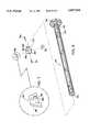
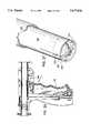
- FIG. 1is a perspective view of one embodiment of a tissue removing instrument constructed in accordance with the present disclosure
- FIG. 2is a perspective view with parts separated, of the embodiment of FIG. 1;
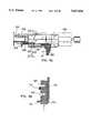
- FIG. 3is a partial view of the interior distal end of one handle half-section of the embodiment of FIG. 1;
- FIG. 4is an enlarged view of the area of detail indicated in FIG. 2;
- FIG. 5is a perspective view, with parts separated, of the concentrically disposed tool mechanisms of the embodiment of FIG. 1;
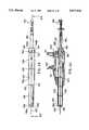
- FIG. 6is a perspective view, with parts separated, of the obturator of the embodiment of FIG. 1;
- FIG. 7is an enlarged view of the area of detail indicated in FIG. 6;
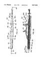
- FIG. 8is a perspective view, with parts separated, of the elongated tissue coring tube of the embodiment of FIG. 1;
- FIG. 9is a perspective view of the tissue coring tube of FIG. 8, which shows the reverse side of the distal end of the tube;
- FIG. 10is a perspective view, with parts separated, of the cutting wire and support tube of the embodiment of FIG. 1;
- FIG. 11is an enlarged perspective view of the distal end of the cutting wire positioned on the support tube
- FIG. 12is a horizontal cross-sectional view of the embodiment of FIG. 1;
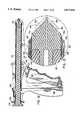
- FIG. 13is an enlarged view of the indicated area of detail of the distal end of the instrument shown in FIG. 12;
- FIG. 14is an initial view showing the embodiment of FIG. 1 in use
- FIG. 15is a further view, similar to FIG. 14, showing the embodiment of FIG. 1 in use;
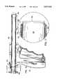
- FIG. 16is a horizontal cross-sectional view of the embodiment FIG. 1 with the obturator removed therefrom;
- FIG. 17is an enlarged view of the area of detail indicated in FIG. 16;
- FIG. 18is a cross-sectional view taken along section line 18--18 of FIG. 16;
- FIG. 19is a view, similar to FIG. 18, showing operational features of the instrument
- FIG. 20is a cross-sectional view of the proximal end of the embodiment of FIG. 1, showing the lockout lever in the locked position;
- FIG. 21is a view, similar to FIG. 20, showing the lockout lever in the released position
- FIG. 22is a view, similar to FIG. 17, showing the movement of the central elongated tube
- FIG. 23is a further view, similar to FIG. 14, showing the embodiment of FIG. 1 in use;
- FIG. 24is a view of the distal end of the embodiment of FIG. 1 inserted around target tissue;
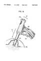
- FIG. 25is a view, similar to FIG. 24, showing deployment of the cutting loop of wire and retaining strap;
- FIG. 26is a horizontal cross-sectional view showing the proximal end of the instrument during operation of the trigger
- FIG. 27is a view, similar to FIGS. 24 and 25, showing complete deployment of the cutting loop of wire and retaining strap;
- FIG. 28is a perspective view of a further embodiment constructed in accordance with the present disclosure and mounted on a cooperative portion of a stereotactic imaging machine;
- FIG. 29is a longitudinal cross-sectional view from the top of the embodiment of FIG. 28;
- FIG. 30is a perspective view, with parts separated, of the components contained in the housing or handle portion of the embodiment of FIG. 28;
- FIG. 31is a cross-sectional view taken along section line 31--31 of FIG. 29;
- FIG. 32is a cross-sectional top view of the proximal end of the embodiment of FIG. 28;
- FIG. 33is a cross-sectional view taken along section line 33--33 of FIG. 32;
- FIG. 34is a view, similar to FIG. 32, showing the operation of various elements of the embodiment of FIG. 28;
- FIG. 35is a cross-sectional view taken along section line 35--35 of FIG. 34;
- FIG. 36is a view demonstrating a sequence of operation of the embodiment of FIG. 28 as mounted on a cooperative portion of a stereotactic imaging machine;
- FIG. 37is a view, similar to FIG. 36, demonstrating a further sequence of operation of the embodiment of FIG. 28;
- FIG. 38is a view, similar to FIG. 36, demonstrating a further sequence of operation of the embodiment of FIG. 28;
- FIG. 39is a view, similar to FIG. 36, demonstrating a further sequence of operation of the embodiment of FIG. 28;
- FIG. 40is a view, similar to FIG. 36, demonstrating a further sequence of operation of the embodiment of FIG. 28;
- FIG. 41is a perspective view of a further embodiment of a tissue removing apparatus constructed in accordance with the present disclosure.
- FIG. 42is a perspective view of a further embodiment of a tissue removing apparatus constructed in accordance with the present disclosure.
- FIG. 43is a side elevational view of the embodiment of FIG. 42;
- FIG. 44is a cross-sectional view taken along section line 44--44 of FIG. 43;
- FIG. 45is perspective view of a rack assembly for manually effectuating rotation of a portion of a tissue removing apparatus
- FIG. 46is a top view of the rack assembly shown in FIG. 45;
- FIG. 47is a side elevational view of a further alternative embodiment tissue removing apparatus.
- FIG. 48is a cross-sectional view taken along section line 48--48 of FIG. 47;
- FIG. 49is a side elevational view of a further alternative embodiment tissue removing apparatus.
- FIG. 50is a cross-sectional view taken along section line 50--50 of FIG. 49.
- an instrument for removing and/or taking a biopsy of tissuein accordance with the present disclosure is designated by reference numeral 100 throughout the several views.
- the instrument 100is particularly adapted for minimally invasive insertion into tissue immediately adjacent the target tissue, and then for coring out and removing the target tissue from the patient. It will be understood by those skilled in the art, however, that the embodiments of the tissue removing instrument described herein, although generally directed to removal of breast tissue, may also be utilized for removal and/or biopsy of target tissue from other areas of a patient's body as well.
- instrument 100includes a housing such as body portion 110 (formed from handle half-sections 112 and 114), and an elongated tubular body portion 116.
- a penetrating member, such as obturator 118extends through a longitudinal passageway of instrument 100 and extends out the distal end.
- An actuator, for example trigger 120is preferably pivotally mounted in an opening formed between handle half-sections 112 and 114.
- the materials utilized in the components of the instrumentgenerally include such materials as polycarbonate for housing sections and related components, and stainless steel for components which transmit forces.
- One preferred polycarbonate materialis available from General Electric under the tradename LEXAN. It is also preferred that radiolucent materials be utilized for appropriate instrument components, e.g., elongated tubular portions, so as not to interfere with imaging of tissue positioned adjacent thereto.
- handle half-sections 112 and 114are preferably molded to have predetermined contoured regions for housing the various components as well as facilitating the instrument's operation.
- Each of the handle half-sections 112 and 114has a grip portion 122, in the shape of a pistol grip, which extends generally transversely away from a longitudinal axis "L" of a barrel portion formed when handle half-sections 112 and 114 are joined.
- Opposed semi-cylindrical walls 128 and 130form a generally cylindrical passageway with adjacent semi-cylindrical portions, i.e., raised wall portion 136 and semi-annular groove 144, from the proximal end of body 110 to the distal end thereof.
- Handle half-sections 112 and 114may be joined together by any suitable means, for example, by sonic welding, snap fit, securing screw(s), adhesive bonding or the like.
- elongated tubular portion 116includes a series of elongated components which are preferably concentrically disposed with respect to each other.
- An outer tubular sheath 132has a proximal end held securely between semi-cylindrical walls 128 and 130 and a distal end which is covered by a collar 133 securely attached thereto.
- a pair of transversely extending tab portions 134are formed at the proximal end of outer tubular sheath 132 and fit into slots 135 formed at the juncture of semi-cylindrical walls 128, 130 and raised portions 135. Tab portions 134 bias against raised portions 136 to prevent proximal movement of outer tubular sheath 132 when the instrument 100 is inserted into the body tissue.
- a tubular membersuch as central tubular shaft 138, is axially and rotatably movable within outer tubular sheath 132.
- the rotation of central tubular shaft 138may be selectively prevented by a mechanism described in detail below.
- central tubular shaft 138may be temporarily and selectively maintained in a fixed axial position relative to barrel portion 126 of body 110. This fixed axial relationship may be accomplished, for example, by a cylindrical protrusion 140 (FIG. 9) formed near the proximal end of central tubular shaft 138 being positioned in an annular groove formed by closing semi-annular groove portions 142 and 144 formed in handle half-sections 112 and 114, respectively. In this manner, central tubular shaft 138 may remain fixed axially within body 110 so as to freely rotate therein but not be removed therefrom.
- Obturator 118is slidably positioned within central tubular shaft 138 and is preferably designed to cooperate with central tubular shaft 138 so as to prevent rotation of both central tubular shaft 138 and obturator 118 during the initial insertion of instrument 100 into the patient.
- a preferred manner in which to accomplish this selective fixing of the rotational movement of both central tubular shaft 138 and obturator 118 as well as to prevent relative axial movement of those components with respect to each other as well as body 110is best shown in FIGS. 2, 3 and 5.
- a pin 146is transversely secured in elongated shaft 148 of obturator 118 near its proximal end.
- pin 146is received in a slot 150 formed in a collar 152, which is secured to the proximal end of central tubular shaft 138.
- This relationship between obturator 118 and central tubular shaft 138prevents relative rotational movement between the two components.
- the subassembly of obturator 118 and central tubular shaft 138is secured in body 110 by a bayonet-type mount, FIG.
- L-shaped groove 154is preferably provided with a lip 156 which serves to maintain pin 146 in the locked-out position.
- Lockout lever 158is pivotably mounted to body 110 and is temporarily maintained in the locked-out position by raised portions 160 extending laterally from the side surfaces of lockout lever 158 near a proximal end thereof being seated in detents 162 formed along the inner surface of handle portions of 112 and 114, respectively, at a position proximal of the groove formed by semi-annular groove portions 142 and 144.
- raised portions 160extending laterally from the side surfaces of lockout lever 158 near a proximal end thereof being seated in detents 162 formed along the inner surface of handle portions of 112 and 114, respectively, at a position proximal of the groove formed by semi-annular groove portions 142 and 144.
- Trigger 120is preferably pivotably attached to body 110 in recessed portions 164 and 166 formed in the handle half-sections 112 and 114.
- Trigger 120is connected to a tissue cutting member, e.g., a filament or wire, such as wire 168, by a pin extending through a throughbore formed near the top of trigger 120 (FIG. 16).
- Wire 168is maintained in a preferred orientation by an elongated tubular sheath 170 which is preferably concentrically disposed within outer tubular sheath 132 such that laterally extending tab portions 172 are situated adjacent tab portions 134 and maintained between housing handle half-sections 112 and 114 as described above for outer tubular sheath 132.
- a longitudinal slot 174is formed beginning at the proximal end of outer tubular sheath 132 and is disposed between laterally extending tab portions 134 so as to receive wire 168 and permit movement of the wire loop with respect to outer tubular sheath 132.
- obturator 118includes elongated shaft 148, a cutting head 176 secured to a distal end of the shaft and a knob 178 attached to a proximal end of the shaft to facilitate insertion and removal of the obturator 118 from the instrument 100.
- Cutting head 176is preferably provided with slots 180 and 182, formed orthogonally with respect to each other and which are dimensioned to receive individual blades 184 such that a cutting edge 186 formed on each blade 184 is angled to correspond to the angled distal surfaces 188 of the cutting head 176.
- individual blades 184are each provided with a transversely extending slot 188 having a series of individual tooth members 190 extending from the side wall of the slot.
- Teeth 190are preferably formed in the shape of a ramp-shaped camming surface to interlock with complimentary surfaces (not shown) formed within orthogonally disposed slots 180 and 182.
- Cutting head 176is in the shape of a plug member having a proximally extending portion 192 of reduced diameter which is inserted into a bore 194 formed at the distal end of obturator 118 so as to be fixedly secured thereto. Any suitable known techniques for mounting may be utilized, such as friction fitting, bonding, adhesives or the like.
- central tubular shaft 138has a tissue cutting surface, such as annular cutting edge 196 formed at the distal end to facilitate coring of the tissue surrounding and including the target tissue within the patient.
- the shaftis preferably formed of a material suitable for forming a sharpened edge, such as, for example, stainless steel.
- a knob 198is secured to the proximal end of central tubular shaft 138, for example, by locking tabs 200 engaging cut out portions 202 formed in cylindrical section 152 of knob 198.
- Knob 198is preferably further provided with a knurled gripping surface 206 to facilitate rotation of the shaft during the coring action of the tissue. Such rotational movement is facilitated by the disposition of pin 140 within the annular groove formed by semi-annular groove portions 142 and 144, as noted above.
- wire 168facilitates the severing of the tissue core to permit removal of the targeted tissue from the patient and, optionally, delivers electrocautery current to the tissue as cutting is accomplished.
- Wire 168is preferably formed of a single length of thin gauge, stainless steel wire which is bent to an initial configuration or pre-fired condition contained within instrument 100, as shown in FIG. 10.
- wire 168is folded in half such that free ends 208 and 210 are positioned at the proximal end and are formed into a U-shaped bend to hook around pin 212 disposed at the top of trigger 120 (FIGS. 2 and 17).
- Wire 168extends longitudinally along the outer surface of elongated tubular sheath 170 to the distal end thereof.
- a circular loop 213is formed at the distal end of wire 168 and is positioned adjacent a flange 214 formed at the distal end of the tubular sheath 170.
- Flange 214is provided with radially extending leg portions 218 which form diametrically opposed passageways which hold wire 168 in a position substantially aligned with the distal end of tubular sheath 170.
- a tissue retaining membersuch as strap 216, is wrapped around circular loop 213 and is provided with a tabbed end portion 220 to maintain the positioning of the strap across the distal opening of elongated tubular sheath upon cutting of the tissue core, which will explained in greater detail herein.
- FIG. 12The relative positioning of the various structural subassemblies in the initial configuration of instrument 100 is shown in the longitudinal cross-sectional view of FIG. 12.
- obturator 118is shown inserted in instrument 100 with lockout lever 158 preventing proximal movement of central tubular shaft 138.
- wire 168is maintained in position by central tubular shaft 138 and obturator 118 on the interior side and by collar 133 on the exterior side. Wire 168 cannot be deployed to cut tissue until both obturator 118 and central tubular shaft 138 are moved distally of loop 213 (FIG. 10).
- FIGS. 14-27A preferred method of using instrument 100 is illustrated in FIGS. 14-27.
- Instrument 100is inserted into the breast tissue along a predetermined path toward the target tissue 222.
- the location of the target tissuecan be specifically determined through the use of known localization techniques, such as for example, the insertion of a localization needle and/or the use of a stereotactic mammography device.
- the target tissuemay be tagged with a tagging device and instrument 100 moved adjacent the tagged location under conventional imaging guidance, or instrument 100 may be adapted to move along a target tissue locating device, such as a conventional K-wire, which was pre-positioned adjacent or across the target tissue.
- Instrument 100may cooperate with a target tissue locating device in a variety of manners such as sliding coaxially along such locating device.
- obturator 118is first rotated in a counterclockwise fashion as indicated by arrow "A” in FIG. 14, by the user gripping knob 178 and rotating the knob in a counterclockwise fashion. This rotational movement disengages pin 146 from L-shaped groove 154 (FIGS. 3 and 6) to permit axial movement of obturator 118 relative to the instrument 100.
- obturator 118may be removed from the instrument 100 by pulling on knob 178 in a proximal direction as indicated by arrow "B" in FIG. 14.
- the target tissueis cored out from the surrounding tissue by urging instrument 100 in a proximal direction as indicated by arrow "C” in FIG. 15, while simultaneously turning knob 198 of central tubular shaft 138 to cause rotation of annular cutting edge 196 at the distal end of the central tubular shaft 138.
- Rotation of the elongated central tubular shaft 138may be in either a clockwise or counterclockwise direction or both depending on the preference of the user, as indicated by arrow "D" in FIG. 15.
- central tubular shaft 138When the target tissue is completely within the distal end of instrument 100, central tubular shaft 138 is moved proximally to allow for deployment of wire loop 168 to sever the tissue core from the patient. Electrocautery current is optionally delivered to the tissue by wire loop 168 as severing is accomplished. As shown in FIGS. 16 and 17, elongated central tubular shaft 138 is shown extending distally from the distal end of instrument 100 and preventing wire loop 168 from moving out of alignment with the circumferential alignment with the distal end of elongated tubular sheath 170.
- FIG. 18shows the relative positioning of pin 140 within annular groove 141 to facilitate the rotation of elongated central tubular shaft 138 therein. Such rotation is possible when the obturator 118 is removed from instrument 100.
- knob 198is rotated, as indicated by arrow "E” in FIG. 19, to align pin 140 with a keyway 224 formed in handle half-sections 112 and 114. This alignment permits proximal movement of central tubular shaft 138 when lever lockout 158 is pushed down, as indicated by arrow “F” in FIG. 21, to release protrusion 160 from detent 162 (FIGS. 2 and 4).
- Knob 198is pulled proximally as indicated by arrow "G” in FIG. 21 to move the distal end of central tubular shaft 138 proximal of wire loop 213.
- Instrument 100may thus be removed from the patient's breast. Due to the partial obstruction of the distal end opening of elongated tubular sheath 170 by strap 214, the severed tissue core will be removed from the patient with instrument 100. To the extent necessary, the puncture wound left by instrument 100 may be closed by any suitable known suturing techniques.
- FIGS. 28-40Another embodiment of the presently disclosed instrument for removing and/or taking a biopsy of target tissue and a method of its use are illustrated in FIGS. 28-40.
- instrument 300is particularly adapted for use on a precision instrument positioning machine, for example, a stereotactic imaging machine.
- a precision instrument positioning machinefor example, a stereotactic imaging machine.
- Such devicesare commercially available, for example, from Lorad Corporation of Danbury, Conn..
- An example of such a machineis disclosed in U.S. Pat. No. 5,289,520 which issued Feb. 22, 1994 to Pellegrino et al., the contents of which are hereby incorporated by reference.
- stereotactic machinesfacilitate stereo x-ray imaging of a patient's breast using a three dimensional coordinate system, while the patient is in a prone position on a specially designed table.
- An openingis provided on the table to permit the patient's breast to be pendulantly disposed therethrough and a clamp is used to fix the exact location of the patient's pendulant breast relative to the operational components of the machine which facilitate precision interaction of instrumentation with the breast, i.e. for biopsy or tissue removal.
- instrument 300is shown mounted in place on the instrument positioning control mechanism of a stereotactic machine, generally designated by reference numeral 302.
- Stereotactic machine 302has an instrument mount 304, the movement of which is coordinated with the imaging capabilities of the machine.
- the instrument mount 304is provided with a standardized instrument or tool mounting bracket 305 to facilitate mounting of various surgical instruments which can take advantage of the precision positioning features of the stereotactic machine. This is particularly beneficial in procedures where the target tissue is not palpable.
- the cooperative structures on instrument 300 and stereotactic machine 302may be reconfigured so that more structure is included on instrument 300 and less on machine 302, or vice versa. All that is required is that stereotactic machine 302 and instrument 300 cooperate so as to position instrument 300 as desired with respect to the target tissue.
- Instrument 300is provided with four slide mounts 306, two of which are formed on each side of housing half-sections 312 and 314 so that instrument 300 can be mounted on either side.
- the mechanical operational controls of instrument 300all of which are positioned on the same side of the instrument, may be oriented to suit the preference of the personnel using the instrument during the particular procedure. It is envisioned that some of the control actuators of instrument 300 may be reconfigured so that they would be operable from a different side than the remaining control actuators.
- Housing half-sections 312 and 314are preferably molded to conform to the dimensions of the stereotactic machine tool mounting bracket 305, for example, a rectangular base dimension.
- Obturator 318has a pair of resiliently formed retaining members 319 each of which include a shoulder portion 321 which engages a cut-out portion of the proximal end wall of housing half-section 314 to maintain obturator 318 in place during insertion of instrument 300.
- a firing lockout mechanismis provided to prevent premature movement of the cutting wire before obturator 318 and central tubular shaft 338 are properly positioned relative to the wire loop positioned at the distal end of wire 368 (similar to loop 213 of wire 168).
- the firing lockout mechanismincludes a safety lockout member 323 and a control member, such as slide bar member 341.
- Lockout member 323is slidably received in a cutout 325 formed in a sidewall of housing half-section 314 and has a pair of slotted keyways 327 and 329 formed thereon.
- raised portions 331which provide tactile indication to the user of the relative positioning of lockout member 323 during a two-stage lockout release process described below.
- Trigger 320is provided with a retaining pin 333 which has a pair of bores formed therethrough to receive and frictionally retain wire loop 368.
- a latch portion 335is formed extending from the distal side of trigger 320 which is configured and dimensioned to interact with lockout member 323 and specifically to slide in keyway 327.
- a preferred manual drive mechanism 700is depicted in FIGS. 45 and 46 and includes a mounting body 702 which is adapted to be mounted to a stereotactic imaging apparatus by way of mounting apertures 704.
- a rack 706is movably mounted to mounting body 702 and includes a plurality of teeth 708 and a pair of elbow handles 710, 712 at either end thereof. Inclined faces 714 on rack 706 cooperate with abutment faces 716 and overhang 718 on mounting body 702 to mount rack 706 with respect to mounting body 702.
- Transverse movement of rack 706 with respect to mounting body 702is limited by stops 722, 724 formed on rack 706.
- the size and spacing of teeth 708are selected to cooperate with the teeth of gear 339.
- the number of teeth 708 on rack 706are selected to effectuate the degree of rotation of gear 339 desired, e.g., 90°, 180°, 360°, etc.
- transverse movement of rack 706effectuates rotational movement of gear 339 and concomitant rotation of tubular shaft 338.
- a powered drive mechanismmay be provided on stereotactic machine 302.
- a slide bar 341cradles gear collar 337 to permit rotational movement thereof while controlling the axial alignment of central tubular shaft 338 within housing halfsections 312 and 314.
- Slide bar 341is provided with a latch portion 343 formed at a proximal end thereof. At the distal end, slide bar 341 has actuator button 345 to facilitate proximal movement of slide bar 341 by the user.
- Another feature of slide bar 341is a diagonal groove 347 which is formed in the side surface adjacent the proximal end of the slide bar to permit wire loop 368 to slidably pass therethrough, as best seen in FIG. 29.
- FIGS. 31-35The two stage lockout process of lockout member 323 is best shown in FIGS. 31-35 in conjunction with FIGS. 36-40.
- FIGS. 36 and 37it is desirable to maintain the relative axial positioning of central tubular shaft 338 with respect to outer tubular sheath 332 as well as to prevent firing of trigger 320.
- Both of these preventive goalsare accomplished when obturator 318 is positioned within the instrument and lockout member 323 is maintained in its initial position as shown in FIG. 29 by obturator member 318 and shoulder portion 349 of lockout member 323 biasing against the outer wall of housing half-section 314. In this position, keyways 327 and 329 of lockout member 323 are maintained out of alignment with slide bar 341 and latch portion 335 of trigger 320, respectively.
- obturator 318is removed (FIGS. 29 and 38) by pressing radially inwardly on retaining members 319 to disengage the retaining members from shoulder portions 321 from the proximal end wall of housing half-section 314.
- lockout member 323is free to move transversely toward the central longitudinal axis of instrument 300.
- the first stage of releasing lockout member 323, illustrated in FIG. 32,is accomplished when the user pushes lockout member 323 inwardly toward the center of the instrument. A tactile indication is felt by the user when the first raised portion 331 passes over the side wall of housing half-section 314.
- Actuator button 345is moved proximally, as indicated by arrow "J" in FIG. 32, to effect proximal movement of central tubular shaft 138. This proximal movement is limited by partition 351 formed transversely across housing half-section 314.
- latch portionpasses through keyway 327 and prevents further transverse movement of lockout member 323 until latch portion 343 passes completely through keyway 327.
- lockout member 323is again pushed transversely inward (see FIGS. 32 and 33) until the user feels another tactile indication, resulting from the second raised portion 331 crossing over the side wall of housing half-section 314.
- latch 335 of trigger 320is aligned with keyway 329.
- Trigger 320is moved proximally in the direction of arrow "KI”.
- latch portion 343 of slide bar 341is in engagement with lockout member 323 to prevent distal movement of slide bar 341 and, therefore, central tubular shaft 338, during firing of trigger 320.
- FIG. 41A further embodiment of a tissue removing instrument is shown in FIG. 41.
- Instrument 400is similar to the embodiment of FIGS. 28-40 and is designed to be inserted and used manually by a surgeon, rather than in conjunction with a stereotactic machine.
- the handle of instrument 400includes handle half-sections 412 and 414 which are molded to a dimension suitable for being held in the palm of either the user's left or right hands.
- the control mechanisms of instrument 400may be the same as those for instrument 300 or lockout member 323 may be eliminated as shown in FIG. 41.
- the basic manner of usage of instrumentis the same as that for instrument 300.
- FIGS. 42-44Another embodiment of the apparatus for removing tissue constructed in accordance with the present disclosure is illustrated in FIGS. 42-44 as instrument 500.
- instrument 500The overall structural and operational features of instrument 500 are very similar to those described above for instrument 300.
- a wire loop similar to wire loop 368 of instrument 300is also utilized to sever the tissue enclosed by instrument 500 in the same manner as in instrument 300, optionally with cautery.
- the wire loopis not shown. It is to be understood, however, that the wire loop of instrument 500 is fully incorporated in instrument 500 and performs the same function(s) of wire loop 368 in instrument 300 in the same manner.
- Instrument 500is designed to be mounted on a stereotactic machine in the same manner as instrument 300.
- instrument 500is provided with a blunt obturator 518 that is preferably formed of a two part polycarbonate housing having half-sections 518a and 518b.
- the half-sections 518a and 518bare advantageous in that they facilitate assembling blunt obturator 518 around a surgical instrument, preferably an instrument designed for use in minimally invasive procedures, for example, elongated biopsy tissue marker 601.
- surgeonsmay take advantage of the precision positioning capabilities of a stereotactic imaging apparatus to precisely insert and bring the working components of such minimally invasive instruments to precise locations to conduct the desired procedure. It will be understood by those skilled in the art that different blunt obturators may be configured and dimensioned to receive a variety of instruments, thereby mating such instrumentation with instrument 500.
- blunt obturator 518preferably includes a distal end surface 517 which is planar and includes a central aperture to facilitate the passage of the distal end of a particular instrument inserted therethrough, e.g., distal end 603 of biopsy tissue marker 601.
- Blunt obturator 518is further provided with a series of alignment portions which are preferably a series of spaced apart, axially aligned supports 525 formed along the inner surface of blunt obturator 518.
- Supports 525advantageously facilitate maintaining the axial alignment of an instrument, e.g. instrument 601, inserted through blunt obturator 518 by defining a longitudinal passageway through blunt obturator 518.
- the longitudinal channel defined by supports 525is coaxially aligned with a longitudinal channel defined by instrument 500 housing half-sections 512 and 514.
- a locking mechanismis also provided which facilitates blunt obturator 518 being fixedly retained in instrument 500 during movement of instrument 500 during portions of the surgical procedure.
- one advantage of maintaining obturator 518 in place relative to instrument 500is to precisely introduce an instrument disposed in obturator 518 into the patient with instrument 500.
- a further advantage of maintaining blunt obturator 518 in place during insertion of instrument 500 into the tissue of the patient, e.g. into the breast tissue of a female patient in a breast biopsy procedure,is that annular cutting edge 596, located at the distal end of central tubular shaft 538, is prevented from coring tissue which is not intended to be cored by instrument 500.
- the locking mechanismincludes retainer clips 519 formed on collar 583.
- Retainer clips 519are preferably flexible such that upon insertion of obturator 518 into an opening formed on the proximal end wall formed by housing half-sections 512 and 514, a shoulder portion similar to shoulder portion 321 of retaining members 319 (FIG. 29) engages the inner surface of the proximal end wall of instrument 500.
- a mounting tube 585may be provided, as necessary, to facilitate mounting particular surgical instruments, such as instrument 601, to blunt obturator 518. As shown in FIG. 44, mounting tube 585 has notches 587 formed adjacent a distal end to facilitate a snap fit into an aperture defined by housing half-sections 518a and 518b. Instrument 601 may be attached to mounting tube 585 by any suitable known mounting structure or technique, for example, a quick connect mechanism, snap fit, fasteners, or the like.
- Slide bar 541serves to retract central tubular shaft 538 in a manner similar to slide bar 341 of instrument 300 (FIG. 30) and includes actuator grips 545 positioned at the distal end of instrument 500 adjacent fixed handle 521. In this manner, once the tissue enclosed by instrument 500 is ready to be cut, central tubular shaft 538 is retracted by pulling grips 545 to expose the wire loop cutting member (as shown in FIG. 22 for instrument 100).
- FIGS. 47, 48 and 49, 50two contemplated obturator embodiments are depicted in FIGS. 47, 48 and in FIGS. 49, 50, respectively.
- an instrumentis provided which includes a plurality of telescoping dilators which may be sequentially advanced from the distal end of the elongated body portion to dilate tissue in a step-like or gradual manner.
- an instrumentis provided which includes an inflatable dilating structure.
- instrument 800 of FIGS. 47 and 48includes a first dilating structure 850, a second dilating structure 852, and a third dilating structure 854.
- Each of such dilating structures 850, 852, 854define a central aperture 850a, 852a, 854a, respectively, of increasing diameter.
- the diameter of aperture 850ais such that it receives an instrument, e.g. instrument 603, therethrough and advantageously maintains axial alignment therewith.
- Aperture 852ain turn is sized to receive first dilating structure 850 therethrough, and aperture 854a is sized to receive second dilating structure 852 therethrough.
- first, second and third dilating structures 850, 852, 854define telescoping members which gradually increase the degree to which tissue is dilated.
- Each dilating memberincludes a conical face at its distal end (e.g., conical face 850b) to effectuate tissue dilation, although other geometries are also contemplated, e.g., pyramidal, and may also be utilized to effectuate dilation.
- first dilating structure 850defines a barrel extension 850b and a flange 850c.
- Flange 850cis sized to abut flange 852c formed at the proximal end of second dilating structure 852 and flange 852c is sized to abut flange 854c formed at the proximal end of third dilating structure 854.
- the surgeonwould first advance first dilating structure distally relative to second dilating structure 852, thereby bringing flange 850c into abutment with flange 852c.
- This distal movementalso advances the conical face at the distal end of first dilating structure from elongated tube 816 and effectuates a degree of tissue dilation. Thereafter, both flange 850c and flange 852c are advanced distally until flange 852c abuts flange 854c. This movement effects distal movement of the conical face at the distal end of second dilating structure 852 and effectuates further tissue dilation.
- the conical faces of respective dilating structuresregister with each other such that a substantially continuous conical face is formed as respective dilating structures are distally advanced.
- third dilating structure 854is distally advanced, thereby further dilating issue, until flange 854c abuts stop 856.
- dilating structuresmay be employed to effectuate the desired tissue dilation.
- angle of the conical facemay be varied to effect different rates and resistances to dilation.
- Instrument 900includes a fluid conduit 950 at its proximal end which is preferably opened and closed by a valve mechanism (not shown), e.g., a stopcock.
- Fluid conduit 950communicates with an axial fluid passage 952 which extends distally into an inflatable balloon 954 positioned at a distal end of a hollow rod 956 which receives a surgical instrument, e.g., instrument 603, and is movably mounted with respect to elongated tube 916.
- Balloon 954is adhered to rod 956 such that the introduction of an inflationary fluid, e.g., saline, does not cause separation of balloon 954 therefrom.
- an inflationary fluide.g., saline
- Suitable adhesives as are known in the artare generally employed for this purpose.
- balloon 954is shown inflated within elongated tube 916, it is contemplated that in use balloon 954 would remain non-inflated until advanced distally from elongated tube 916 into tissue.
- a stabilizing disk 958is provided on rod 956 and advantageously maintains rod 956 in axial alignment with elongated tube 916.
- a stop 960interacts with the body 962 of the valve mechanism to limit distal movement of rod 956, and thus balloon 954.
- knife 938is initially withdrawn and body 962 is advanced distally relative to elongated body 916, thereby advancing balloon 954 from within elongated body 916.
- Inflating fluide.g., saline or air
- Balloon 954is thus inflated and effectuates tissue dilation in a controlled and atraumatic manner.
- balloon 954is deflated, e.g., by reversing the syringe action, and withdrawn into elongated tube 916. The procedure may then proceed as discussed hereinabove.
Landscapes
- Health & Medical Sciences (AREA)
- Life Sciences & Earth Sciences (AREA)
- Surgery (AREA)
- Medical Informatics (AREA)
- Biomedical Technology (AREA)
- Heart & Thoracic Surgery (AREA)
- Engineering & Computer Science (AREA)
- Molecular Biology (AREA)
- Pathology (AREA)
- Animal Behavior & Ethology (AREA)
- General Health & Medical Sciences (AREA)
- Public Health (AREA)
- Veterinary Medicine (AREA)
- Nuclear Medicine, Radiotherapy & Molecular Imaging (AREA)
- Surgical Instruments (AREA)
Abstract
Description
Claims (16)
Priority Applications (7)
| Application Number | Priority Date | Filing Date | Title |
|---|---|---|---|
| US08/546,482US5817034A (en) | 1995-09-08 | 1995-10-20 | Apparatus and method for removing tissue |
| US08/665,176US5782775A (en) | 1995-10-20 | 1996-06-14 | Apparatus and method for localizing and removing tissue |
| DE29623929UDE29623929U1 (en) | 1995-09-08 | 1996-09-06 | Device for removing tissue |
| EP00117346AEP1051946A3 (en) | 1995-09-08 | 1996-09-06 | Apparatus and method for removing tissue |
| CA002184973ACA2184973A1 (en) | 1995-09-08 | 1996-09-06 | Apparatus and method for removing tissue |
| EP96114296AEP0761170A3 (en) | 1995-09-08 | 1996-09-06 | Apparatus for removing tissue |
| US09/158,632US6213957B1 (en) | 1995-09-08 | 1998-09-22 | Apparatus and method for removing tissue |
Applications Claiming Priority (2)
| Application Number | Priority Date | Filing Date | Title |
|---|---|---|---|
| US08/525,450US5857982A (en) | 1995-09-08 | 1995-09-08 | Apparatus and method for removing tissue |
| US08/546,482US5817034A (en) | 1995-09-08 | 1995-10-20 | Apparatus and method for removing tissue |
Related Parent Applications (1)
| Application Number | Title | Priority Date | Filing Date |
|---|---|---|---|
| US08/525,450Continuation-In-PartUS5857982A (en) | 1995-09-08 | 1995-09-08 | Apparatus and method for removing tissue |
Related Child Applications (2)
| Application Number | Title | Priority Date | Filing Date |
|---|---|---|---|
| US08/665,176Continuation-In-PartUS5782775A (en) | 1995-10-20 | 1996-06-14 | Apparatus and method for localizing and removing tissue |
| US09/158,632ContinuationUS6213957B1 (en) | 1995-09-08 | 1998-09-22 | Apparatus and method for removing tissue |
Publications (1)
| Publication Number | Publication Date |
|---|---|
| US5817034Atrue US5817034A (en) | 1998-10-06 |
Family
ID=27061797
Family Applications (2)
| Application Number | Title | Priority Date | Filing Date |
|---|---|---|---|
| US08/546,482Expired - LifetimeUS5817034A (en) | 1995-09-08 | 1995-10-20 | Apparatus and method for removing tissue |
| US09/158,632Expired - LifetimeUS6213957B1 (en) | 1995-09-08 | 1998-09-22 | Apparatus and method for removing tissue |
Family Applications After (1)
| Application Number | Title | Priority Date | Filing Date |
|---|---|---|---|
| US09/158,632Expired - LifetimeUS6213957B1 (en) | 1995-09-08 | 1998-09-22 | Apparatus and method for removing tissue |
Country Status (4)
| Country | Link |
|---|---|
| US (2) | US5817034A (en) |
| EP (2) | EP1051946A3 (en) |
| CA (1) | CA2184973A1 (en) |
| DE (1) | DE29623929U1 (en) |
Cited By (67)
| Publication number | Priority date | Publication date | Assignee | Title |
|---|---|---|---|---|
| US6080113A (en)* | 1998-09-11 | 2000-06-27 | Imagyn Medical Technologies California, Inc. | Incisional breast biopsy device |
| DE10026508A1 (en)* | 2000-05-24 | 2001-11-29 | Kai Desinger | Surgical hollow tube |
| US6383145B1 (en) | 1997-09-12 | 2002-05-07 | Imagyn Medical Technologies California, Inc. | Incisional breast biopsy device |
| US6428508B1 (en)* | 2000-02-01 | 2002-08-06 | Enlighten Technologies, Inc. | Pulsed vacuum cataract removal system |
| US20030004530A1 (en)* | 1998-01-27 | 2003-01-02 | Kyphon Inc. | Slip-fit handle for hand-held instruments that access interior body regions |
| US6530936B1 (en)* | 1998-06-03 | 2003-03-11 | Yeong Seok Yun | Apparatus for harvesting cartilage |
| US6551253B2 (en) | 1997-09-12 | 2003-04-22 | Imagyn Medical Technologies | Incisional breast biopsy device |
| US20030082797A1 (en)* | 1999-12-17 | 2003-05-01 | Michel Rastorgoueff | Device and method for taking biological sample |
| US6569176B2 (en) | 1999-10-18 | 2003-05-27 | Jerry M. Jesseph | Device and method for improved diagnosis and treatment of cancer |
| US20030187459A1 (en)* | 2002-03-26 | 2003-10-02 | Image-Guided Neurologics, Inc. | Placement of chronic micro-catheter device and method |
| US20030191488A1 (en)* | 2002-04-09 | 2003-10-09 | Braden Robison | Surgical instrument |
| US20030229341A1 (en)* | 2002-06-06 | 2003-12-11 | Albrecht Thomas E. | Method of tissue lesion removal |
| USD495413S1 (en) | 2003-05-16 | 2004-08-31 | Scimed Life Systems, Inc. | Fluid delivery device |
| US20050090762A1 (en)* | 1998-03-03 | 2005-04-28 | Senorx, Inc. | Electrosurgical biopsy device and method |
| US20050203625A1 (en)* | 2000-11-13 | 2005-09-15 | Boehm Frank H.Jr. | Device and method for lumbar interbody fusion |
| US6976968B2 (en) | 1999-10-18 | 2005-12-20 | Ritchart Mark A | Methods and devices for collection of soft tissue |
| US6981949B2 (en) | 2002-06-06 | 2006-01-03 | Ethicon Endo-Surgery, Inc. | Perimeter cut biopsy probe |
| US20060047296A1 (en)* | 2004-08-31 | 2006-03-02 | Sdg Holdings, Inc. | Annulus replacement system and technique |
| US7066893B2 (en) | 2002-06-06 | 2006-06-27 | Ethicon Endo-Surgery, Inc. | Biopsy method |
| US20060173377A1 (en)* | 2005-01-31 | 2006-08-03 | Mccullough Adam B | Quick cycle biopsy system |
| US20060178698A1 (en)* | 2005-02-08 | 2006-08-10 | Mcintyre Jon T | Method and device for canulation and occlusion of uterine arteries |
| US20060224084A1 (en)* | 2005-04-05 | 2006-10-05 | Vetter James W | Methods and devices for removing tissue from a patient |
| US20060229528A1 (en)* | 2003-03-29 | 2006-10-12 | C. R. Brad, Inc. | Coaxial cannula provided with a sealing element |
| US20070149894A1 (en)* | 2002-03-19 | 2007-06-28 | C.R. Bard, Inc. | Biopsy device for removing tissue specimens using a vacuum |
| US20070149893A1 (en)* | 2002-03-19 | 2007-06-28 | C.R. Bard, Inc. | Biopsy device and biopsy needle module that can be inserted into the biopsy device |
| US20080039884A1 (en)* | 2006-08-10 | 2008-02-14 | Nohilly Martin J | Morcellator with detachable handle |
| WO2008020439A2 (en) | 2006-08-17 | 2008-02-21 | Sialo Technology Israel Ltd | All-in-one optical microscopic handle |
| US7357801B2 (en) | 1998-04-08 | 2008-04-15 | Senorx, Inc. | Tissue specimen isolating and damaging device and method |
| US7601125B1 (en) | 1999-06-17 | 2009-10-13 | Desinger Kai | Surgical, grooved director for collecting tissue in a minimally invasive manner |
| US7641668B2 (en) | 2003-05-16 | 2010-01-05 | Scimed Life Systems, Inc. | Fluid delivery system and related methods of use |
| US20100030108A1 (en)* | 2006-10-24 | 2010-02-04 | C.R. Bard, Inc. | Large sample low aspect ratio biopsy needle |
| US20100140500A1 (en)* | 2007-06-19 | 2010-06-10 | Therapy Positioning Technologies, Llc | Apparatus and method for the treatment of breast cancer with particle beams |
| US7762961B2 (en) | 2003-03-29 | 2010-07-27 | C. R. Bard, Inc. | Pressure generating unit |
| US20100210967A1 (en)* | 2007-08-02 | 2010-08-19 | Sjunnesson Haakan | Surgical kits and methods |
| WO2011123446A1 (en) | 2010-03-30 | 2011-10-06 | Flatland Martin L | Tissue excision device |
| US8052615B2 (en) | 2004-07-09 | 2011-11-08 | Bard Peripheral Vascular, Inc. | Length detection system for biopsy device |
| US8251917B2 (en) | 2006-08-21 | 2012-08-28 | C. R. Bard, Inc. | Self-contained handheld biopsy needle |
| US8262585B2 (en) | 2005-08-10 | 2012-09-11 | C. R. Bard, Inc. | Single-insertion, multiple sampling biopsy device with linear drive |
| US8267868B2 (en) | 2005-08-10 | 2012-09-18 | C. R. Bard, Inc. | Single-insertion, multiple sample biopsy device with integrated markers |
| US8282574B2 (en) | 2005-08-10 | 2012-10-09 | C. R. Bard, Inc. | Single-insertion, multiple sampling biopsy device usable with various transport systems and integrated markers |
| US20130103151A1 (en)* | 2002-11-05 | 2013-04-25 | Medgenics Medical Israel Ltd | Dermal micro-organs, methods and apparatuses for producing and using the same |
| US8430824B2 (en) | 2009-10-29 | 2013-04-30 | Bard Peripheral Vascular, Inc. | Biopsy driver assembly having a control circuit for conserving battery power |
| US8454532B2 (en) | 2007-12-27 | 2013-06-04 | Devicor Medical Products, Inc. | Clutch and valving system for tetherless biopsy device |
| US8485987B2 (en) | 2006-10-06 | 2013-07-16 | Bard Peripheral Vascular, Inc. | Tissue handling system with reduced operator exposure |
| US8485989B2 (en) | 2009-09-01 | 2013-07-16 | Bard Peripheral Vascular, Inc. | Biopsy apparatus having a tissue sample retrieval mechanism |
| US8597205B2 (en) | 2007-12-20 | 2013-12-03 | C. R. Bard, Inc. | Biopsy device |
| US8597206B2 (en) | 2009-10-12 | 2013-12-03 | Bard Peripheral Vascular, Inc. | Biopsy probe assembly having a mechanism to prevent misalignment of components prior to installation |
| US8690793B2 (en) | 2009-03-16 | 2014-04-08 | C. R. Bard, Inc. | Biopsy device having rotational cutting |
| US8708928B2 (en) | 2009-04-15 | 2014-04-29 | Bard Peripheral Vascular, Inc. | Biopsy apparatus having integrated fluid management |
| US8845548B2 (en) | 2009-06-12 | 2014-09-30 | Devicor Medical Products, Inc. | Cutter drive assembly for biopsy device |
| US9107896B2 (en) | 2001-11-05 | 2015-08-18 | Medgenics Medical Israel Ltd. | Dermal micro-organs, methods and apparatuses for producing and using the same |
| US9173641B2 (en) | 2009-08-12 | 2015-11-03 | C. R. Bard, Inc. | Biopsy apparatus having integrated thumbwheel mechanism for manual rotation of biopsy cannula |
| US9216012B2 (en) | 1998-09-01 | 2015-12-22 | Senorx, Inc | Methods and apparatus for securing medical instruments to desired locations in a patient's body |
| USD768848S1 (en)* | 2014-08-18 | 2016-10-11 | Mark L. Anderson | Dosing counter |
| US9468667B2 (en) | 2001-11-05 | 2016-10-18 | Medgenics Medical Israel Ltd. | Dermal micro-organs, methods and apparatuses for producing and using the same |
| US10004498B2 (en) | 2006-01-31 | 2018-06-26 | Ethicon Llc | Surgical instrument comprising a plurality of articulation joints |
| US10251630B2 (en) | 2015-08-28 | 2019-04-09 | SiteSelect Inc. | Tissue excision device with anchor stability rod and anchor stability rod |
| US10278676B2 (en)* | 2012-06-27 | 2019-05-07 | Michael J. Vaillancourt | Safety shield for a needle assembly |
| US10285673B2 (en) | 2013-03-20 | 2019-05-14 | Bard Peripheral Vascular, Inc. | Biopsy device |
| US10456120B2 (en) | 2013-11-05 | 2019-10-29 | C. R. Bard, Inc. | Biopsy device having integrated vacuum |
| US10463350B2 (en) | 2015-05-01 | 2019-11-05 | C. R. Bard, Inc. | Biopsy device |
| US11116483B2 (en) | 2017-05-19 | 2021-09-14 | Merit Medical Systems, Inc. | Rotating biopsy needle |
| US11793498B2 (en) | 2017-05-19 | 2023-10-24 | Merit Medical Systems, Inc. | Biopsy needle devices and methods of use |
| US11844500B2 (en) | 2017-05-19 | 2023-12-19 | Merit Medical Systems, Inc. | Semi-automatic biopsy needle device and methods of use |
| US12150627B2 (en) | 2019-12-11 | 2024-11-26 | Merit Medical Systems, Inc. | Bone biopsy device and related methods |
| US20250099087A1 (en)* | 2022-04-05 | 2025-03-27 | Resitu Medical Ab | A biopsy instrument |
| US12295556B2 (en) | 2019-09-27 | 2025-05-13 | Merit Medical Systems, Inc. | Rotation biopsy system and handle |
Families Citing this family (138)
| Publication number | Priority date | Publication date | Assignee | Title |
|---|---|---|---|---|
| US5857982A (en)* | 1995-09-08 | 1999-01-12 | United States Surgical Corporation | Apparatus and method for removing tissue |
| US5817034A (en)* | 1995-09-08 | 1998-10-06 | United States Surgical Corporation | Apparatus and method for removing tissue |
| US5782775A (en)* | 1995-10-20 | 1998-07-21 | United States Surgical Corporation | Apparatus and method for localizing and removing tissue |
| CA2214873A1 (en)* | 1996-10-04 | 1998-04-04 | United States Surgical Corporation | Surgical system for tissue removal |
| US6039748A (en)* | 1997-08-05 | 2000-03-21 | Femrx, Inc. | Disposable laparoscopic morcellator |
| EP1011455B1 (en)* | 1997-09-12 | 2007-01-10 | SiteSelect Medical Technologies, Ltd. | Incisional breast biopsy device |
| US8668737B2 (en) | 1997-10-10 | 2014-03-11 | Senorx, Inc. | Tissue marking implant |
| US7637948B2 (en) | 1997-10-10 | 2009-12-29 | Senorx, Inc. | Tissue marking implant |
| AU9326698A (en)* | 1997-11-24 | 1999-06-10 | Johnson & Johnson Research Pty. Limited | Biopsy instrument including tip for tissue dilation |
| JP4157183B2 (en)* | 1998-02-17 | 2008-09-24 | オリンパス株式会社 | Endoscopic treatment tool |
| US8361082B2 (en) | 1999-02-02 | 2013-01-29 | Senorx, Inc. | Marker delivery device with releasable plug |
| US6862470B2 (en) | 1999-02-02 | 2005-03-01 | Senorx, Inc. | Cavity-filling biopsy site markers |
| US6725083B1 (en) | 1999-02-02 | 2004-04-20 | Senorx, Inc. | Tissue site markers for in VIVO imaging |
| US7983734B2 (en) | 2003-05-23 | 2011-07-19 | Senorx, Inc. | Fibrous marker and intracorporeal delivery thereof |
| US20090030309A1 (en) | 2007-07-26 | 2009-01-29 | Senorx, Inc. | Deployment of polysaccharide markers |
| US9820824B2 (en) | 1999-02-02 | 2017-11-21 | Senorx, Inc. | Deployment of polysaccharide markers for treating a site within a patent |
| US7651505B2 (en) | 2002-06-17 | 2010-01-26 | Senorx, Inc. | Plugged tip delivery for marker placement |
| US8498693B2 (en) | 1999-02-02 | 2013-07-30 | Senorx, Inc. | Intracorporeal marker and marker delivery device |
| DE19908721A1 (en)* | 1999-03-01 | 2000-09-28 | Storz Karl Gmbh & Co Kg | Instrument for cutting biological and especially human tissue |
| US6575991B1 (en) | 1999-06-17 | 2003-06-10 | Inrad, Inc. | Apparatus for the percutaneous marking of a lesion |
| CA2659518A1 (en) | 2000-11-20 | 2002-05-30 | Senorx, Inc. | Tissue site markers for in vivo imaging |
| US20030050648A1 (en) | 2001-09-11 | 2003-03-13 | Spiration, Inc. | Removable lung reduction devices, systems, and methods |
| EP1293167A3 (en)* | 2001-09-14 | 2003-12-17 | TuiLaser AG | Instrument for cutting and removing tissue |
| US6592594B2 (en) | 2001-10-25 | 2003-07-15 | Spiration, Inc. | Bronchial obstruction device deployment system and method |
| US7494499B2 (en)* | 2002-02-15 | 2009-02-24 | Olympus Corporation | Surgical therapeutic instrument |
| US20030216769A1 (en) | 2002-05-17 | 2003-11-20 | Dillard David H. | Removable anchored lung volume reduction devices and methods |
| US20030181922A1 (en) | 2002-03-20 | 2003-09-25 | Spiration, Inc. | Removable anchored lung volume reduction devices and methods |
| US6852108B2 (en) | 2002-05-14 | 2005-02-08 | Spiration, Inc. | Apparatus and method for resecting and removing selected body tissue from a site inside a patient |
| US6793678B2 (en) | 2002-06-27 | 2004-09-21 | Depuy Acromed, Inc. | Prosthetic intervertebral motion disc having dampening |
| EP2305812A3 (en)* | 2002-11-14 | 2012-06-06 | Dharmacon, Inc. | Fuctional and hyperfunctional sirna |
| US20060036158A1 (en) | 2003-11-17 | 2006-02-16 | Inrad, Inc. | Self-contained, self-piercing, side-expelling marking apparatus |
| US7100616B2 (en) | 2003-04-08 | 2006-09-05 | Spiration, Inc. | Bronchoscopic lung volume reduction method |
| US7632288B2 (en) | 2003-05-12 | 2009-12-15 | Boston Scientific Scimed, Inc. | Cutting balloon catheter with improved pushability |
| US7877133B2 (en) | 2003-05-23 | 2011-01-25 | Senorx, Inc. | Marker or filler forming fluid |
| US7758604B2 (en)* | 2003-05-29 | 2010-07-20 | Boston Scientific Scimed, Inc. | Cutting balloon catheter with improved balloon configuration |
| US7169114B2 (en)* | 2003-06-04 | 2007-01-30 | Krause William R | Biopsy and delivery device |
| US7533671B2 (en) | 2003-08-08 | 2009-05-19 | Spiration, Inc. | Bronchoscopic repair of air leaks in a lung |
| US20050273002A1 (en) | 2004-06-04 | 2005-12-08 | Goosen Ryan L | Multi-mode imaging marker |
| US7270673B2 (en)* | 2003-12-31 | 2007-09-18 | Boston Scientific Scimed, Inc. | Microsurgical balloon with protective reinforcement |
| US7879054B2 (en)* | 2004-03-11 | 2011-02-01 | Boston Scientific Scimed, Inc. | System and method for tissue sampling and therapeutic treatment |
| US7754047B2 (en) | 2004-04-08 | 2010-07-13 | Boston Scientific Scimed, Inc. | Cutting balloon catheter and method for blade mounting |
| US7566319B2 (en) | 2004-04-21 | 2009-07-28 | Boston Scientific Scimed, Inc. | Traction balloon |
| US7440793B2 (en)* | 2004-07-22 | 2008-10-21 | Sunita Chauhan | Apparatus and method for removing abnormal tissue |
| US20060030872A1 (en)* | 2004-08-03 | 2006-02-09 | Brad Culbert | Dilation introducer for orthopedic surgery |
| US9387313B2 (en)* | 2004-08-03 | 2016-07-12 | Interventional Spine, Inc. | Telescopic percutaneous tissue dilation systems and related methods |
| ITBO20040532A1 (en)* | 2004-08-26 | 2004-11-26 | Aticarta S P A | RIGID WRAPPING FOR SMOKING ITEMS WITH HINGED COVER CONNECTED BY GLUING |
| USD538429S1 (en)* | 2004-09-14 | 2007-03-13 | Karl Storz Gmbh & Co. Kg | Trocar for use with morcellator |
| US20060074345A1 (en) | 2004-09-29 | 2006-04-06 | Hibner John A | Biopsy apparatus and method |
| US8038691B2 (en) | 2004-11-12 | 2011-10-18 | Boston Scientific Scimed, Inc. | Cutting balloon catheter having flexible atherotomes |
| US7291158B2 (en)* | 2004-11-12 | 2007-11-06 | Boston Scientific Scimed, Inc. | Cutting balloon catheter having a segmented blade |
| US8419656B2 (en)* | 2004-11-22 | 2013-04-16 | Bard Peripheral Vascular, Inc. | Post decompression marker introducer system |
| US20060184191A1 (en)* | 2005-02-11 | 2006-08-17 | Boston Scientific Scimed, Inc. | Cutting balloon catheter having increased flexibility regions |
| WO2006108067A2 (en)* | 2005-04-05 | 2006-10-12 | Triage Medical, Inc. | Tissue dilation systems and related methods |
| US10357328B2 (en) | 2005-04-20 | 2019-07-23 | Bard Peripheral Vascular, Inc. and Bard Shannon Limited | Marking device with retractable cannula |
| WO2007014313A2 (en) | 2005-07-26 | 2007-02-01 | Precision Thoracic Corporation | Minimally invasive methods and apparatus |
| US7854707B2 (en) | 2005-08-05 | 2010-12-21 | Devicor Medical Products, Inc. | Tissue sample revolver drum biopsy device |
| USRE46135E1 (en) | 2005-08-05 | 2016-09-06 | Devicor Medical Products, Inc. | Vacuum syringe assisted biopsy device |
| US7867173B2 (en)* | 2005-08-05 | 2011-01-11 | Devicor Medical Products, Inc. | Biopsy device with replaceable probe and incorporating vibration insertion assist and static vacuum source sample stacking retrieval |
| US7828748B2 (en)* | 2005-08-05 | 2010-11-09 | Devicor Medical Products, Inc. | Vacuum syringe assisted biopsy device |
| US7896817B2 (en) | 2005-08-05 | 2011-03-01 | Devicor Medical Products, Inc. | Biopsy device with manually rotated sample barrel |
| US7662109B2 (en)* | 2006-02-01 | 2010-02-16 | Ethicon Endo-Surgery, Inc. | Biopsy device with replaceable probe incorporating static vacuum source dual valve sample stacking retrieval and saline flush |
| US20080004545A1 (en)* | 2005-08-05 | 2008-01-03 | Garrison William A | Trigger Fired Radial Plate Specimen Retrieval Biopsy Instrument |
| JP4575257B2 (en)* | 2005-09-06 | 2010-11-04 | オリンパスメディカルシステムズ株式会社 | Tissue biopsy needle device |
| US8052658B2 (en) | 2005-10-07 | 2011-11-08 | Bard Peripheral Vascular, Inc. | Drug-eluting tissue marker |
| US7691151B2 (en) | 2006-03-31 | 2010-04-06 | Spiration, Inc. | Articulable Anchor |
| WO2008051749A2 (en) | 2006-10-23 | 2008-05-02 | C. R. Bard, Inc. | Breast marker |
| WO2008070863A2 (en) | 2006-12-07 | 2008-06-12 | Interventional Spine, Inc. | Intervertebral implant |
| US9579077B2 (en) | 2006-12-12 | 2017-02-28 | C.R. Bard, Inc. | Multiple imaging mode tissue marker |
| US7981049B2 (en)* | 2006-12-13 | 2011-07-19 | Devicor Medical Products, Inc. | Engagement interface for biopsy system vacuum module |
| US8702623B2 (en)* | 2008-12-18 | 2014-04-22 | Devicor Medical Products, Inc. | Biopsy device with discrete tissue chambers |
| US8251916B2 (en)* | 2006-12-13 | 2012-08-28 | Devicor Medical Products, Inc. | Revolving tissue sample holder for biopsy device |
| US8480595B2 (en) | 2006-12-13 | 2013-07-09 | Devicor Medical Products, Inc. | Biopsy device with motorized needle cocking |
| US20130324882A1 (en) | 2012-05-30 | 2013-12-05 | Devicor Medical Products, Inc. | Control for biopsy device |
| US20140039343A1 (en) | 2006-12-13 | 2014-02-06 | Devicor Medical Products, Inc. | Biopsy system |
| US7938786B2 (en)* | 2006-12-13 | 2011-05-10 | Devicor Medical Products, Inc. | Vacuum timing algorithm for biopsy device |
| US9345457B2 (en) | 2006-12-13 | 2016-05-24 | Devicor Medical Products, Inc. | Presentation of biopsy sample by biopsy device |
| WO2008076973A2 (en) | 2006-12-18 | 2008-06-26 | C.R.Bard Inc. | Biopsy marker with in situ-generated imaging properties |
| US8900307B2 (en) | 2007-06-26 | 2014-12-02 | DePuy Synthes Products, LLC | Highly lordosed fusion cage |
| US8052616B2 (en)* | 2007-11-20 | 2011-11-08 | Devicor Medical Products, Inc. | Biopsy device with fine pitch drive train |
| US8454531B2 (en) | 2007-11-20 | 2013-06-04 | Devicor Medical Products, Inc. | Icon-based user interface on biopsy system control module |
| US20090131819A1 (en)* | 2007-11-20 | 2009-05-21 | Ritchie Paul G | User Interface On Biopsy Device |
| US7858038B2 (en)* | 2007-11-20 | 2010-12-28 | Devicor Medical Products, Inc. | Biopsy device with illuminated tissue holder |
| US7806835B2 (en)* | 2007-11-20 | 2010-10-05 | Devicor Medical Products, Inc. | Biopsy device with sharps reduction feature |
| US7575556B2 (en)* | 2007-11-20 | 2009-08-18 | Ethicon Endo-Surgery, Inc. | Deployment device interface for biopsy device |
| US9039634B2 (en)* | 2007-11-20 | 2015-05-26 | Devicor Medical Products, Inc. | Biopsy device tissue sample holder rotation control |
| US20090131821A1 (en)* | 2007-11-20 | 2009-05-21 | Speeg Trevor W V | Graphical User Interface For Biopsy System Control Module |
| EP2237748B1 (en) | 2008-01-17 | 2012-09-05 | Synthes GmbH | An expandable intervertebral implant |
| WO2009099767A2 (en) | 2008-01-31 | 2009-08-13 | C.R. Bard, Inc. | Biopsy tissue marker |
| US8936641B2 (en) | 2008-04-05 | 2015-01-20 | DePuy Synthes Products, LLC | Expandable intervertebral implant |
| US8449478B2 (en)* | 2008-05-16 | 2013-05-28 | Conquest Medical Technologies | Biopsy device |
| USD604847S1 (en)* | 2008-06-13 | 2009-11-24 | Karl Storz Gmbh & Co. Kg | Morcellator |
| US9327061B2 (en) | 2008-09-23 | 2016-05-03 | Senorx, Inc. | Porous bioabsorbable implant |
| EP4215147A3 (en) | 2008-12-30 | 2023-10-18 | C. R. Bard, Inc. | Marker delivery device for tissue marker placement |
| US9526620B2 (en) | 2009-03-30 | 2016-12-27 | DePuy Synthes Products, Inc. | Zero profile spinal fusion cage |
| US9393129B2 (en) | 2009-12-10 | 2016-07-19 | DePuy Synthes Products, Inc. | Bellows-like expandable interbody fusion cage |
| US9907560B2 (en) | 2010-06-24 | 2018-03-06 | DePuy Synthes Products, Inc. | Flexible vertebral body shavers |
| US8979860B2 (en) | 2010-06-24 | 2015-03-17 | DePuy Synthes Products. LLC | Enhanced cage insertion device |
| US8623091B2 (en) | 2010-06-29 | 2014-01-07 | DePuy Synthes Products, LLC | Distractible intervertebral implant |
| US9402732B2 (en) | 2010-10-11 | 2016-08-02 | DePuy Synthes Products, Inc. | Expandable interspinous process spacer implant |
| US9968337B2 (en)* | 2010-12-20 | 2018-05-15 | Cook Medical Technologies Llc | Coring tissue biopsy needle and method of use |
| US8657760B2 (en)* | 2011-03-04 | 2014-02-25 | Cook Medical Technologies Llc | Ergonomic biopsy instrument |
| US8795241B2 (en) | 2011-05-13 | 2014-08-05 | Spiration, Inc. | Deployment catheter |
| EP2877127B1 (en) | 2012-07-26 | 2019-08-21 | Synthes GmbH | Expandable implant |
| US20140067069A1 (en) | 2012-08-30 | 2014-03-06 | Interventional Spine, Inc. | Artificial disc |
| CA2879636C (en) | 2012-09-28 | 2020-06-09 | Covidien Lp | Optical trocar visualization system and apparatus |
| US9717601B2 (en) | 2013-02-28 | 2017-08-01 | DePuy Synthes Products, Inc. | Expandable intervertebral implant, system, kit and method |
| US9522070B2 (en) | 2013-03-07 | 2016-12-20 | Interventional Spine, Inc. | Intervertebral implant |
| USD716451S1 (en) | 2013-09-24 | 2014-10-28 | C. R. Bard, Inc. | Tissue marker for intracorporeal site identification |
| USD715442S1 (en) | 2013-09-24 | 2014-10-14 | C. R. Bard, Inc. | Tissue marker for intracorporeal site identification |
| USD716450S1 (en) | 2013-09-24 | 2014-10-28 | C. R. Bard, Inc. | Tissue marker for intracorporeal site identification |
| USD715942S1 (en) | 2013-09-24 | 2014-10-21 | C. R. Bard, Inc. | Tissue marker for intracorporeal site identification |
| US10390806B2 (en) | 2014-03-28 | 2019-08-27 | Covidien Lp | Devices, systems, and methods for obtaining a tissue sample using a biopsy tool |
| US11426290B2 (en) | 2015-03-06 | 2022-08-30 | DePuy Synthes Products, Inc. | Expandable intervertebral implant, system, kit and method |
| US10695038B2 (en) | 2015-04-20 | 2020-06-30 | Covidien Lp | Devices, systems, and methods for obtaining a tissue sample |
| US9913727B2 (en) | 2015-07-02 | 2018-03-13 | Medos International Sarl | Expandable implant |
| US11510788B2 (en) | 2016-06-28 | 2022-11-29 | Eit Emerging Implant Technologies Gmbh | Expandable, angularly adjustable intervertebral cages |
| EP3474784A2 (en) | 2016-06-28 | 2019-05-01 | Eit Emerging Implant Technologies GmbH | Expandable and angularly adjustable intervertebral cages with articulating joint |
| US10537436B2 (en) | 2016-11-01 | 2020-01-21 | DePuy Synthes Products, Inc. | Curved expandable cage |
| US10888433B2 (en) | 2016-12-14 | 2021-01-12 | DePuy Synthes Products, Inc. | Intervertebral implant inserter and related methods |
| WO2018144898A1 (en)* | 2017-02-02 | 2018-08-09 | Precision Thoracic, Llc | Minimally invasive methods apparatus for target-tissue excision |
| US10398563B2 (en) | 2017-05-08 | 2019-09-03 | Medos International Sarl | Expandable cage |
| US11344424B2 (en) | 2017-06-14 | 2022-05-31 | Medos International Sarl | Expandable intervertebral implant and related methods |
| US10940016B2 (en) | 2017-07-05 | 2021-03-09 | Medos International Sarl | Expandable intervertebral fusion cage |
| US20200038089A1 (en) | 2018-07-31 | 2020-02-06 | Ethicon, Inc. | Tissue resection apparatus |
| US11446156B2 (en) | 2018-10-25 | 2022-09-20 | Medos International Sarl | Expandable intervertebral implant, inserter instrument, and related methods |
| US11357542B2 (en) | 2019-06-21 | 2022-06-14 | Covidien Lp | Valve assembly and retainer for surgical access assembly |
| US11812991B2 (en) | 2019-10-18 | 2023-11-14 | Covidien Lp | Seal assemblies for surgical access assemblies |
| US11426286B2 (en) | 2020-03-06 | 2022-08-30 | Eit Emerging Implant Technologies Gmbh | Expandable intervertebral implant |
| US11642153B2 (en) | 2020-03-19 | 2023-05-09 | Covidien Lp | Instrument seal for surgical access assembly |
| US11541218B2 (en) | 2020-03-20 | 2023-01-03 | Covidien Lp | Seal assembly for a surgical access assembly and method of manufacturing the same |
| US11446058B2 (en) | 2020-03-27 | 2022-09-20 | Covidien Lp | Fixture device for folding a seal member |
| US11717321B2 (en) | 2020-04-24 | 2023-08-08 | Covidien Lp | Access assembly with retention mechanism |
| US11287531B2 (en) | 2020-07-14 | 2022-03-29 | Spirent Communications, Plc | Architecture for providing forecasts of GNSS obscuration and multipath |
| GB2599110B (en)* | 2020-09-24 | 2024-12-18 | Jessup Mark | Cutting instrument with safety sleeve |
| DE102020124917A1 (en) | 2020-09-24 | 2022-03-24 | Frank Schure | Medical instrument for minimally invasive removal of biological material from a human or animal body |
| US11850160B2 (en) | 2021-03-26 | 2023-12-26 | Medos International Sarl | Expandable lordotic intervertebral fusion cage |
| US11752009B2 (en) | 2021-04-06 | 2023-09-12 | Medos International Sarl | Expandable intervertebral fusion cage |
| US12090064B2 (en) | 2022-03-01 | 2024-09-17 | Medos International Sarl | Stabilization members for expandable intervertebral implants, and related systems and methods |
Citations (52)
| Publication number | Priority date | Publication date | Assignee | Title |
|---|---|---|---|---|
| DE263228C (en)* | ||||
| US1568008A (en)* | 1925-05-09 | 1925-12-29 | Cecil C Thomas | Implement for removing cores from citrous fruits |
| US1609456A (en)* | 1925-12-03 | 1926-12-07 | Charles H Boyle | Coring device |
| US2117278A (en)* | 1937-09-07 | 1938-05-17 | George C Ainsworth | Fruit corer |
| US2541542A (en)* | 1946-02-13 | 1951-02-13 | Perez Guillermo Herrera | Trocar for biopsia |
| US3470867A (en)* | 1964-11-23 | 1969-10-07 | Sidney Goldsmith | Biopsy needle |
| US3477423A (en)* | 1967-01-09 | 1969-11-11 | Baxter Laboratories Inc | Biopsy instrument |
| US3605721A (en)* | 1969-11-03 | 1971-09-20 | Ismet Hallac | Biopsy needle |
| US3628524A (en)* | 1969-02-28 | 1971-12-21 | Khosrow Jamshidi | Biopsy needle |
| CH534505A (en)* | 1969-06-30 | 1973-03-15 | Hubert Dr Reinisch | Biopsy collection device |
| US4010737A (en)* | 1971-06-14 | 1977-03-08 | Vilaghy Miklos I | Bone biopsy instrument kit |
| US4099518A (en)* | 1976-05-10 | 1978-07-11 | Baylis Shelby M | Biopsy apparatus |
| US4174715A (en)* | 1977-03-28 | 1979-11-20 | Hasson Harrith M | Multi-pronged laparoscopy forceps |
| US4177797A (en)* | 1977-03-04 | 1979-12-11 | Shelby M. Baylis | Rotary biopsy device and method of using same |
| US4306570A (en)* | 1980-08-20 | 1981-12-22 | Matthews Larry S | Counter rotating biopsy needle |
| WO1982001988A1 (en)* | 1980-12-15 | 1982-06-24 | George C Baumgartner | Surgical instrument and process |
| US4461305A (en)* | 1981-09-04 | 1984-07-24 | Cibley Leonard J | Automated biopsy device |
| US4651752A (en)* | 1985-03-08 | 1987-03-24 | Fuerst Erwin J | Biopsy needle |
| US4678459A (en)* | 1984-07-23 | 1987-07-07 | E-Z-Em, Inc. | Irrigating, cutting and aspirating system for percutaneous surgery |
| FR2610508A1 (en)* | 1987-02-10 | 1988-08-12 | Orlovic Radmila | Bone biopsy apparatus |
| US4776346A (en)* | 1984-02-10 | 1988-10-11 | Dan Beraha | Biopsy instrument |
| US4785826A (en)* | 1987-03-02 | 1988-11-22 | Ward John L | Biopsy instrument |
| US4817631A (en)* | 1985-05-23 | 1989-04-04 | Schnepp Pesch Wolfram | Method for removing tissue from a body |
| US4850373A (en)* | 1987-04-13 | 1989-07-25 | Immuno Aktiengesellschaft Fur Chemisch-Medizinische Produkte | Biopsy device |
| US4881550A (en)* | 1987-02-18 | 1989-11-21 | Lutz Kothe | Medical instrument |
| US4926877A (en)* | 1989-04-24 | 1990-05-22 | Bookwalter John R | Biopsy needle with completely closable cutting end bore |
| US4940061A (en)* | 1989-11-27 | 1990-07-10 | Ingress Technologies, Inc. | Biopsy instrument |
| US4958625A (en)* | 1989-07-18 | 1990-09-25 | Boston Scientific Corporation | Biopsy needle instrument |
| US4971067A (en)* | 1988-05-05 | 1990-11-20 | Lee Bolduc | Biopsy instrument with a disposable cutting blade |
| US4989614A (en)* | 1988-02-23 | 1991-02-05 | Vance Products Incorporated | Fine-needle aspiration cell sampling methods |
| US5036860A (en)* | 1989-11-24 | 1991-08-06 | Medical Device Technologies, Inc. | Disposable soft tissue biopsy apparatus |
| US5078142A (en)* | 1989-11-21 | 1992-01-07 | Fischer Imaging Corporation | Precision mammographic needle biopsy system |
| US5111828A (en)* | 1990-09-18 | 1992-05-12 | Peb Biopsy Corporation | Device for percutaneous excisional breast biopsy |
| US5127419A (en)* | 1991-07-02 | 1992-07-07 | Antoine Kaldany | Biopsy instrument with slotted driving member |
| US5133360A (en)* | 1991-03-07 | 1992-07-28 | Spears Colin P | Spears retriever |
| US5148813A (en)* | 1990-11-20 | 1992-09-22 | Bucalo Brian D | Biopsy instrument with tissue specimen retaining and retrieval device |
| US5240011A (en)* | 1991-11-27 | 1993-08-31 | Fischer Imaging Corporation | Motorized biopsy needle positioner |
| US5251641A (en)* | 1992-07-29 | 1993-10-12 | Hgg Laser Fare, Inc. | Biopsy needle |
| US5257632A (en)* | 1992-09-09 | 1993-11-02 | Symbiosis Corporation | Coaxial bone marrow biopsy coring and aspirating needle assembly and method of use thereof |
| US5271414A (en)* | 1992-09-30 | 1993-12-21 | Becton, Dickinson And Company | Biopsy cannula having non-cylindrical interior |
| US5289520A (en)* | 1991-11-27 | 1994-02-22 | Lorad Corporation | Stereotactic mammography imaging system with prone position examination table and CCD camera |
| US5290294A (en)* | 1990-04-17 | 1994-03-01 | Brian Cox | Method and apparatus for removal of a foreign body cavity |
| US5353804A (en)* | 1990-09-18 | 1994-10-11 | Peb Biopsy Corporation | Method and device for percutaneous exisional breast biopsy |
| US5415169A (en)* | 1989-11-21 | 1995-05-16 | Fischer Imaging Corporation | Motorized mammographic biopsy apparatus |
| EP0653191A2 (en)* | 1990-12-18 | 1995-05-17 | YOON, InBae | Safety penetrating instrument |
| US5462062A (en)* | 1991-12-13 | 1995-10-31 | Rubinstein; Daniel B. | Bone marrow biopsy needle with cutting and/or retaining device at distal end |
| US5472426A (en)* | 1991-09-12 | 1995-12-05 | B.E.I. Medical | Cervical discectomy instruments |
| US5483952A (en)* | 1991-09-26 | 1996-01-16 | United States Surgical Corporation | Handle for surgical instruments |
| US5488958A (en)* | 1992-11-09 | 1996-02-06 | Vance Products Incorporated | Surgical cutting instrument for coring tissue affixed thereto |
| US5522398A (en)* | 1994-01-07 | 1996-06-04 | Medsol Corp. | Bone marrow biopsy needle |
| EP0761170A2 (en)* | 1995-09-08 | 1997-03-12 | United States Surgical Corporation | Apparatus for removing tissue |
| WO1997024070A1 (en)* | 1995-12-28 | 1997-07-10 | Jacques Phillibert Janssens | Device for taking a tissue sample |
Family Cites Families (3)
| Publication number | Priority date | Publication date | Assignee | Title |
|---|---|---|---|---|
| US1615494A (en) | 1922-10-12 | 1927-01-25 | John L Waring | Tonsil-removing apparatus |
| WO1993022971A1 (en) | 1992-05-11 | 1993-11-25 | Boston Scientific Corporation | Multiple needle biopsy instrument |
| US5419138A (en) | 1993-07-13 | 1995-05-30 | Laroche Industries, Inc. | Pellet extruding machine |
- 1995
- 1995-10-20USUS08/546,482patent/US5817034A/ennot_activeExpired - Lifetime
- 1996
- 1996-09-06CACA002184973Apatent/CA2184973A1/ennot_activeAbandoned
- 1996-09-06EPEP00117346Apatent/EP1051946A3/ennot_activeWithdrawn
- 1996-09-06DEDE29623929Upatent/DE29623929U1/ennot_activeExpired - Lifetime
- 1996-09-06EPEP96114296Apatent/EP0761170A3/ennot_activeWithdrawn
- 1998
- 1998-09-22USUS09/158,632patent/US6213957B1/ennot_activeExpired - Lifetime
Patent Citations (53)
| Publication number | Priority date | Publication date | Assignee | Title |
|---|---|---|---|---|
| DE263228C (en)* | ||||
| US1568008A (en)* | 1925-05-09 | 1925-12-29 | Cecil C Thomas | Implement for removing cores from citrous fruits |
| US1609456A (en)* | 1925-12-03 | 1926-12-07 | Charles H Boyle | Coring device |
| US2117278A (en)* | 1937-09-07 | 1938-05-17 | George C Ainsworth | Fruit corer |
| US2541542A (en)* | 1946-02-13 | 1951-02-13 | Perez Guillermo Herrera | Trocar for biopsia |
| US3470867A (en)* | 1964-11-23 | 1969-10-07 | Sidney Goldsmith | Biopsy needle |
| US3477423A (en)* | 1967-01-09 | 1969-11-11 | Baxter Laboratories Inc | Biopsy instrument |
| US3628524A (en)* | 1969-02-28 | 1971-12-21 | Khosrow Jamshidi | Biopsy needle |
| CH534505A (en)* | 1969-06-30 | 1973-03-15 | Hubert Dr Reinisch | Biopsy collection device |
| US3605721A (en)* | 1969-11-03 | 1971-09-20 | Ismet Hallac | Biopsy needle |
| US4010737A (en)* | 1971-06-14 | 1977-03-08 | Vilaghy Miklos I | Bone biopsy instrument kit |
| US4099518A (en)* | 1976-05-10 | 1978-07-11 | Baylis Shelby M | Biopsy apparatus |
| US4177797A (en)* | 1977-03-04 | 1979-12-11 | Shelby M. Baylis | Rotary biopsy device and method of using same |
| US4174715A (en)* | 1977-03-28 | 1979-11-20 | Hasson Harrith M | Multi-pronged laparoscopy forceps |
| US4306570A (en)* | 1980-08-20 | 1981-12-22 | Matthews Larry S | Counter rotating biopsy needle |
| WO1982001988A1 (en)* | 1980-12-15 | 1982-06-24 | George C Baumgartner | Surgical instrument and process |
| US4461305A (en)* | 1981-09-04 | 1984-07-24 | Cibley Leonard J | Automated biopsy device |
| US4776346A (en)* | 1984-02-10 | 1988-10-11 | Dan Beraha | Biopsy instrument |
| US4678459A (en)* | 1984-07-23 | 1987-07-07 | E-Z-Em, Inc. | Irrigating, cutting and aspirating system for percutaneous surgery |
| US4651752A (en)* | 1985-03-08 | 1987-03-24 | Fuerst Erwin J | Biopsy needle |
| US4817631A (en)* | 1985-05-23 | 1989-04-04 | Schnepp Pesch Wolfram | Method for removing tissue from a body |
| FR2610508A1 (en)* | 1987-02-10 | 1988-08-12 | Orlovic Radmila | Bone biopsy apparatus |
| US4881550A (en)* | 1987-02-18 | 1989-11-21 | Lutz Kothe | Medical instrument |
| US4785826A (en)* | 1987-03-02 | 1988-11-22 | Ward John L | Biopsy instrument |
| US4850373A (en)* | 1987-04-13 | 1989-07-25 | Immuno Aktiengesellschaft Fur Chemisch-Medizinische Produkte | Biopsy device |
| US4989614A (en)* | 1988-02-23 | 1991-02-05 | Vance Products Incorporated | Fine-needle aspiration cell sampling methods |
| US4971067A (en)* | 1988-05-05 | 1990-11-20 | Lee Bolduc | Biopsy instrument with a disposable cutting blade |
| US4926877A (en)* | 1989-04-24 | 1990-05-22 | Bookwalter John R | Biopsy needle with completely closable cutting end bore |
| US4958625A (en)* | 1989-07-18 | 1990-09-25 | Boston Scientific Corporation | Biopsy needle instrument |
| US5078142A (en)* | 1989-11-21 | 1992-01-07 | Fischer Imaging Corporation | Precision mammographic needle biopsy system |
| US5415169A (en)* | 1989-11-21 | 1995-05-16 | Fischer Imaging Corporation | Motorized mammographic biopsy apparatus |
| US5036860A (en)* | 1989-11-24 | 1991-08-06 | Medical Device Technologies, Inc. | Disposable soft tissue biopsy apparatus |
| US4940061A (en)* | 1989-11-27 | 1990-07-10 | Ingress Technologies, Inc. | Biopsy instrument |
| US5290294A (en)* | 1990-04-17 | 1994-03-01 | Brian Cox | Method and apparatus for removal of a foreign body cavity |
| US5111828A (en)* | 1990-09-18 | 1992-05-12 | Peb Biopsy Corporation | Device for percutaneous excisional breast biopsy |
| US5197484A (en)* | 1990-09-18 | 1993-03-30 | Peb Biopsy Corporation | Method and device for precutaneous excisional breast biopsy |
| US5353804A (en)* | 1990-09-18 | 1994-10-11 | Peb Biopsy Corporation | Method and device for percutaneous exisional breast biopsy |
| US5148813A (en)* | 1990-11-20 | 1992-09-22 | Bucalo Brian D | Biopsy instrument with tissue specimen retaining and retrieval device |
| EP0653191A2 (en)* | 1990-12-18 | 1995-05-17 | YOON, InBae | Safety penetrating instrument |
| US5133360A (en)* | 1991-03-07 | 1992-07-28 | Spears Colin P | Spears retriever |
| US5127419A (en)* | 1991-07-02 | 1992-07-07 | Antoine Kaldany | Biopsy instrument with slotted driving member |
| US5472426A (en)* | 1991-09-12 | 1995-12-05 | B.E.I. Medical | Cervical discectomy instruments |
| US5483952A (en)* | 1991-09-26 | 1996-01-16 | United States Surgical Corporation | Handle for surgical instruments |
| US5289520A (en)* | 1991-11-27 | 1994-02-22 | Lorad Corporation | Stereotactic mammography imaging system with prone position examination table and CCD camera |
| US5240011A (en)* | 1991-11-27 | 1993-08-31 | Fischer Imaging Corporation | Motorized biopsy needle positioner |
| US5462062A (en)* | 1991-12-13 | 1995-10-31 | Rubinstein; Daniel B. | Bone marrow biopsy needle with cutting and/or retaining device at distal end |
| US5251641A (en)* | 1992-07-29 | 1993-10-12 | Hgg Laser Fare, Inc. | Biopsy needle |
| US5257632A (en)* | 1992-09-09 | 1993-11-02 | Symbiosis Corporation | Coaxial bone marrow biopsy coring and aspirating needle assembly and method of use thereof |
| US5271414A (en)* | 1992-09-30 | 1993-12-21 | Becton, Dickinson And Company | Biopsy cannula having non-cylindrical interior |
| US5488958A (en)* | 1992-11-09 | 1996-02-06 | Vance Products Incorporated | Surgical cutting instrument for coring tissue affixed thereto |
| US5522398A (en)* | 1994-01-07 | 1996-06-04 | Medsol Corp. | Bone marrow biopsy needle |
| EP0761170A2 (en)* | 1995-09-08 | 1997-03-12 | United States Surgical Corporation | Apparatus for removing tissue |
| WO1997024070A1 (en)* | 1995-12-28 | 1997-07-10 | Jacques Phillibert Janssens | Device for taking a tissue sample |
Non-Patent Citations (10)
| Title |
|---|
| Biopsys Medical, Inc., The Single Insertion Mammotome Biopsy System, BMI 3473, Feb. 1995, 500.* |
| Biopsys Medical, Inc., The Single-Insertion Mammotome™ Biopsy System, BMI-3473, Feb. 1995, 500. |
| Ismet Hallac, M.D., "A new design in biopsy needles", May 10, 1961, pp. 515-517. |
| Ismet Hallac, M.D., A new design in biopsy needles , May 10, 1961, pp. 515 517.* |
| Lorad, Designing the Future of Breast Biopsy , Product brochure believed to have been published before the applicants filing date.* |
| Lorad, Designing the Future of Breast Biopsy, Product brochure believed to have been published before the applicants' filing date. |
| Mechcatie, E., Stereotactic Breast Biopsies Effective, Less Expensive Than Surgery , OB GYN, Jul. 15, 1994, at 10.* |
| Mechcatie, E., Stereotactic Breast Biopsies Effective, Less Expensive Than Surgery, OB GYN, Jul. 15, 1994, at 10. |
| Mitnick et al., Stereotaxic Localization for Fine Needle Aspiration Breast Biopsy, Arch. Surg., vol. 126, Sep. 1991.* |
| Mitnick et al., Stereotaxic Localization for Fine-Needle Aspiration Breast Biopsy, Arch. Surg., vol. 126, Sep. 1991. |
Cited By (183)
| Publication number | Priority date | Publication date | Assignee | Title |
|---|---|---|---|---|
| US6551253B2 (en) | 1997-09-12 | 2003-04-22 | Imagyn Medical Technologies | Incisional breast biopsy device |
| US6267732B1 (en) | 1997-09-12 | 2001-07-31 | Imagyn Medical Technologies, Inc. | Incisional breast biopsy device |
| US6383145B1 (en) | 1997-09-12 | 2002-05-07 | Imagyn Medical Technologies California, Inc. | Incisional breast biopsy device |
| US20060241627A1 (en)* | 1998-01-27 | 2006-10-26 | Kyphon Inc. | Slip-fit handle for hand-held instruments that access interior body regions |
| US7063703B2 (en)* | 1998-01-27 | 2006-06-20 | Kyphon Inc. | Slip-fit handle for hand-held instruments that access interior body regions |
| US20030004530A1 (en)* | 1998-01-27 | 2003-01-02 | Kyphon Inc. | Slip-fit handle for hand-held instruments that access interior body regions |
| US20050090762A1 (en)* | 1998-03-03 | 2005-04-28 | Senorx, Inc. | Electrosurgical biopsy device and method |
| US7625347B2 (en)* | 1998-03-03 | 2009-12-01 | Senorx, Inc. | Electrosurgical biopsy device and method |
| US7357801B2 (en) | 1998-04-08 | 2008-04-15 | Senorx, Inc. | Tissue specimen isolating and damaging device and method |
| US6530936B1 (en)* | 1998-06-03 | 2003-03-11 | Yeong Seok Yun | Apparatus for harvesting cartilage |
| US9216012B2 (en) | 1998-09-01 | 2015-12-22 | Senorx, Inc | Methods and apparatus for securing medical instruments to desired locations in a patient's body |
| US6080113A (en)* | 1998-09-11 | 2000-06-27 | Imagyn Medical Technologies California, Inc. | Incisional breast biopsy device |
| US9510809B2 (en) | 1999-01-27 | 2016-12-06 | Senorx, Inc. | Tissue specimen isolating and damaging device and method |
| US8636734B2 (en) | 1999-01-27 | 2014-01-28 | Senorx, Inc. | Tissue specimen isolating and damaging device and method |
| US7601125B1 (en) | 1999-06-17 | 2009-10-13 | Desinger Kai | Surgical, grooved director for collecting tissue in a minimally invasive manner |
| US20030233110A1 (en)* | 1999-10-18 | 2003-12-18 | Jesseph Jerry M. | Device and method for improved diagnosis and treatment of cancer |
| US6976968B2 (en) | 1999-10-18 | 2005-12-20 | Ritchart Mark A | Methods and devices for collection of soft tissue |
| US6569176B2 (en) | 1999-10-18 | 2003-05-27 | Jerry M. Jesseph | Device and method for improved diagnosis and treatment of cancer |
| US6792305B2 (en)* | 1999-12-17 | 2004-09-14 | Bio-Rad Pasteur | Device and method for taking biological sample |
| US20030082797A1 (en)* | 1999-12-17 | 2003-05-01 | Michel Rastorgoueff | Device and method for taking biological sample |
| US6428508B1 (en)* | 2000-02-01 | 2002-08-06 | Enlighten Technologies, Inc. | Pulsed vacuum cataract removal system |
| US7094233B2 (en) | 2000-05-24 | 2006-08-22 | Kai Desinger | Hollow surgical probe |
| WO2001089388A1 (en) | 2000-05-24 | 2001-11-29 | Kai Desinger | Surgical, grooved director |
| DE10026508A1 (en)* | 2000-05-24 | 2001-11-29 | Kai Desinger | Surgical hollow tube |
| US20050203625A1 (en)* | 2000-11-13 | 2005-09-15 | Boehm Frank H.Jr. | Device and method for lumbar interbody fusion |
| US8080041B2 (en) | 2000-11-13 | 2011-12-20 | Warsaw Orthopedic, Inc. | Device and method for lumbar interbody fusion |
| US9107896B2 (en) | 2001-11-05 | 2015-08-18 | Medgenics Medical Israel Ltd. | Dermal micro-organs, methods and apparatuses for producing and using the same |
| US9468667B2 (en) | 2001-11-05 | 2016-10-18 | Medgenics Medical Israel Ltd. | Dermal micro-organs, methods and apparatuses for producing and using the same |
| US8172773B2 (en) | 2002-03-19 | 2012-05-08 | C. R. Bard, Inc. | Biopsy device and biopsy needle module that can be inserted into the biopsy device |
| US8002713B2 (en) | 2002-03-19 | 2011-08-23 | C. R. Bard, Inc. | Biopsy device and insertable biopsy needle module |
| US8109885B2 (en) | 2002-03-19 | 2012-02-07 | C. R. Bard, Inc. | Biopsy device for removing tissue specimens using a vacuum |
| US9072502B2 (en) | 2002-03-19 | 2015-07-07 | C. R. Bard, Inc. | Disposable biopsy unit |
| US10335128B2 (en) | 2002-03-19 | 2019-07-02 | C. R. Bard, Inc. | Biopsy device and insertable biopsy needle module |
| US20070149894A1 (en)* | 2002-03-19 | 2007-06-28 | C.R. Bard, Inc. | Biopsy device for removing tissue specimens using a vacuum |
| US20070149893A1 (en)* | 2002-03-19 | 2007-06-28 | C.R. Bard, Inc. | Biopsy device and biopsy needle module that can be inserted into the biopsy device |
| US8016772B2 (en) | 2002-03-19 | 2011-09-13 | C. R. Bard, Inc. | Biopsy device for removing tissue specimens using a vacuum |
| US10271827B2 (en) | 2002-03-19 | 2019-04-30 | C. R. Bard, Inc. | Disposable biopsy unit |
| US9421002B2 (en) | 2002-03-19 | 2016-08-23 | C. R. Bard, Inc. | Disposable biopsy unit |
| US8951209B2 (en) | 2002-03-19 | 2015-02-10 | C. R. Bard, Inc. | Biopsy device and insertable biopsy needle module |
| US8052614B2 (en) | 2002-03-19 | 2011-11-08 | C. R. Bard, Inc. | Biopsy device having a vacuum pump |
| US11382608B2 (en) | 2002-03-19 | 2022-07-12 | C. R. Bard, Inc. | Disposable biopsy unit |
| US9439631B2 (en) | 2002-03-19 | 2016-09-13 | C. R. Bard, Inc. | Biopsy device and insertable biopsy needle module |
| US7588581B2 (en)* | 2002-03-26 | 2009-09-15 | Medtronic, Inc. | Placement of chronic micro-catheter device and method |
| US20030187459A1 (en)* | 2002-03-26 | 2003-10-02 | Image-Guided Neurologics, Inc. | Placement of chronic micro-catheter device and method |
| US7244263B2 (en)* | 2002-04-09 | 2007-07-17 | Stryker Corporation | Surgical instrument |
| US20030191488A1 (en)* | 2002-04-09 | 2003-10-09 | Braden Robison | Surgical instrument |
| US6855140B2 (en) | 2002-06-06 | 2005-02-15 | Thomas E. Albrecht | Method of tissue lesion removal |
| US20030229341A1 (en)* | 2002-06-06 | 2003-12-11 | Albrecht Thomas E. | Method of tissue lesion removal |
| US20050256520A1 (en)* | 2002-06-06 | 2005-11-17 | Albrecht Thomas E | Device for tissue removal |
| US6981949B2 (en) | 2002-06-06 | 2006-01-03 | Ethicon Endo-Surgery, Inc. | Perimeter cut biopsy probe |
| US7510535B2 (en) | 2002-06-06 | 2009-03-31 | Ethicon Endo-Surgery, Inc. | Biopsy method |
| US7670338B2 (en) | 2002-06-06 | 2010-03-02 | Ethicon Endo-Surgery, Inc. | Device for tissue removal |
| US7066893B2 (en) | 2002-06-06 | 2006-06-27 | Ethicon Endo-Surgery, Inc. | Biopsy method |
| US20060241516A1 (en)* | 2002-06-06 | 2006-10-26 | Hibner John A | Biopsy method |
| US20130103151A1 (en)* | 2002-11-05 | 2013-04-25 | Medgenics Medical Israel Ltd | Dermal micro-organs, methods and apparatuses for producing and using the same |
| US8771291B2 (en) | 2002-11-05 | 2014-07-08 | Medgenics Medical Israel Ltd. | Dermal micro-organs, methods and apparatuses for producing and using the same |
| US9101595B2 (en)* | 2002-11-05 | 2015-08-11 | Medgenics Medical Israel Ltd. | Dermal micro-organs, methods and apparatuses for producing and using the same |
| US9706980B2 (en) | 2003-03-29 | 2017-07-18 | C. R. Bard, Inc. | Cannula provided with a sealing element for use in a medical procedure |
| US20060229528A1 (en)* | 2003-03-29 | 2006-10-12 | C. R. Brad, Inc. | Coaxial cannula provided with a sealing element |
| US20110021946A1 (en)* | 2003-03-29 | 2011-01-27 | C.R. Bard, Inc. | Biopsy needle system having a pressure generating unit |
| US7762961B2 (en) | 2003-03-29 | 2010-07-27 | C. R. Bard, Inc. | Pressure generating unit |
| US7740598B2 (en) | 2003-03-29 | 2010-06-22 | C. R. Bard, Inc. | Coaxial cannula provided with a sealing element |
| US20100076341A1 (en)* | 2003-03-29 | 2010-03-25 | C. R. Bard, Inc. | Cannula provided with a sealing element for use in a medical procedure |
| US7645239B2 (en) | 2003-03-29 | 2010-01-12 | C. R. Bard, Inc. | Coaxial cannula provided with a sealing element |
| US8162851B2 (en) | 2003-03-29 | 2012-04-24 | C. R. Bard, Inc. | Biopsy needle system having a pressure generating unit |
| US8845547B2 (en) | 2003-03-29 | 2014-09-30 | C. R. Bard, Inc. | Cannula provided with a sealing element for use in a medical procedure |
| US11071529B2 (en) | 2003-03-29 | 2021-07-27 | C.R. Bard, Inc. | Cannula provided with a sealing element for use in a medical procedure |
| US20070179403A1 (en)* | 2003-03-29 | 2007-08-02 | C.R. Bard, Inc. | Coaxial cannula provided with a sealing element |
| US9980706B2 (en) | 2003-03-29 | 2018-05-29 | C. R. Bard, Inc. | Cannula provided with a sealing element for use in a medical procedure |
| US8728004B2 (en) | 2003-03-29 | 2014-05-20 | C.R. Bard, Inc. | Biopsy needle system having a pressure generating unit |
| US7828747B2 (en) | 2003-03-29 | 2010-11-09 | C. R. Bard, Inc. | Pressure generating unit |
| US9572593B2 (en) | 2003-05-01 | 2017-02-21 | Medgenics Medical Israel Ltd. | Dermal micro-organs, methods and apparatuses for producing and using the same |
| US8147511B2 (en) | 2003-05-16 | 2012-04-03 | Boston Scientific Scimed, Inc. | Fluid delivery system and related methods of use |
| US7641668B2 (en) | 2003-05-16 | 2010-01-05 | Scimed Life Systems, Inc. | Fluid delivery system and related methods of use |
| USD495413S1 (en) | 2003-05-16 | 2004-08-31 | Scimed Life Systems, Inc. | Fluid delivery device |
| US8628555B2 (en) | 2003-05-16 | 2014-01-14 | Boston Scientific Scimed, Inc. | Fluid delivery system and related methods of use |
| US9456809B2 (en) | 2004-07-09 | 2016-10-04 | Bard Peripheral Vascular, Inc. | Tissue sample flushing system for biopsy device |
| US10499888B2 (en) | 2004-07-09 | 2019-12-10 | Bard Peripheral Vascular, Inc. | Tissue sample flushing system for biopsy device |
| US8992440B2 (en) | 2004-07-09 | 2015-03-31 | Bard Peripheral Vascular, Inc. | Length detection system for biopsy device |
| US8926527B2 (en) | 2004-07-09 | 2015-01-06 | Bard Peripheral Vascular, Inc. | Tissue sample flushing system for biopsy device |
| US8864680B2 (en) | 2004-07-09 | 2014-10-21 | Bard Peripheral Vascular, Inc. | Transport system for biopsy device |
| US8366636B2 (en) | 2004-07-09 | 2013-02-05 | Bard Peripheral Vascular, Inc. | Firing system for biopsy device |
| US8052615B2 (en) | 2004-07-09 | 2011-11-08 | Bard Peripheral Vascular, Inc. | Length detection system for biopsy device |
| US9872672B2 (en) | 2004-07-09 | 2018-01-23 | Bard Peripheral Vascular, Inc. | Length detection system for biopsy device |
| US9345458B2 (en) | 2004-07-09 | 2016-05-24 | Bard Peripheral Vascular, Inc. | Transport system for biopsy device |
| US8157744B2 (en) | 2004-07-09 | 2012-04-17 | Bard Peripheral Vascular, Inc. | Tissue sample flushing system for biopsy device |
| US10166011B2 (en) | 2004-07-09 | 2019-01-01 | Bard Peripheral Vascular, Inc. | Transport system for biopsy device |
| US20060047296A1 (en)* | 2004-08-31 | 2006-03-02 | Sdg Holdings, Inc. | Annulus replacement system and technique |
| US8702621B2 (en) | 2005-01-31 | 2014-04-22 | C.R. Bard, Inc. | Quick cycle biopsy system |
| US8012102B2 (en) | 2005-01-31 | 2011-09-06 | C. R. Bard, Inc. | Quick cycle biopsy system |
| US20060173377A1 (en)* | 2005-01-31 | 2006-08-03 | Mccullough Adam B | Quick cycle biopsy system |
| US20090137929A1 (en)* | 2005-01-31 | 2009-05-28 | C. R. Bard, Inc. | Quick cycle biopsy system |
| US11166702B2 (en) | 2005-01-31 | 2021-11-09 | C.R. Bard, Inc. | Quick cycle biopsy system |
| US20070149895A1 (en)* | 2005-01-31 | 2007-06-28 | C.R. Bard, Inc. | Quick cycle biopsy system |
| US7517321B2 (en) | 2005-01-31 | 2009-04-14 | C. R. Bard, Inc. | Quick cycle biopsy system |
| US9161743B2 (en) | 2005-01-31 | 2015-10-20 | C. R. Bard, Inc. | Quick cycle biopsy system |
| US7959580B2 (en) | 2005-01-31 | 2011-06-14 | C.R. Bard, Inc. | Quick cycle biopsy system |
| US8702622B2 (en) | 2005-01-31 | 2014-04-22 | C.R. Bard, Inc. | Quick cycle biopsy system |
| US10058308B2 (en) | 2005-01-31 | 2018-08-28 | C. R. Bard, Inc. | Method for operating a biopsy apparatus |
| US20060178698A1 (en)* | 2005-02-08 | 2006-08-10 | Mcintyre Jon T | Method and device for canulation and occlusion of uterine arteries |
| US20060224084A1 (en)* | 2005-04-05 | 2006-10-05 | Vetter James W | Methods and devices for removing tissue from a patient |
| US8337414B2 (en)* | 2005-04-05 | 2012-12-25 | Encapsule Medical, Llc | Methods and devices for removing tissue from a patient |
| US20100076343A1 (en)* | 2005-04-05 | 2010-03-25 | Vetter James W | Methods and devices for removing tissue from a patient |
| US7635340B2 (en)* | 2005-04-05 | 2009-12-22 | Rubicor Medical, Inc. | Methods and devices for removing tissue from a patient |
| US8721563B2 (en) | 2005-08-10 | 2014-05-13 | C. R. Bard, Inc. | Single-insertion, multiple sample biopsy device with integrated markers |
| US10368849B2 (en) | 2005-08-10 | 2019-08-06 | C. R. Bard, Inc. | Single-insertion, multiple sampling biopsy device usable with various transport systems and integrated markers |
| US8961430B2 (en) | 2005-08-10 | 2015-02-24 | C.R. Bard, Inc. | Single-insertion, multiple sampling biopsy device usable with various transport systems and integrated markers |
| US8728003B2 (en) | 2005-08-10 | 2014-05-20 | C.R. Bard Inc. | Single insertion, multiple sample biopsy device with integrated markers |
| US11219431B2 (en) | 2005-08-10 | 2022-01-11 | C.R. Bard, Inc. | Single-insertion, multiple sampling biopsy device with linear drive |
| US11849928B2 (en) | 2005-08-10 | 2023-12-26 | C. R. Bard, Inc. | Single-insertion, multiple sampling biopsy device usable with various transport systems and integrated markers |
| US8771200B2 (en) | 2005-08-10 | 2014-07-08 | C.R. Bard, Inc. | Single insertion, multiple sampling biopsy device with linear drive |
| US8262585B2 (en) | 2005-08-10 | 2012-09-11 | C. R. Bard, Inc. | Single-insertion, multiple sampling biopsy device with linear drive |
| US8282574B2 (en) | 2005-08-10 | 2012-10-09 | C. R. Bard, Inc. | Single-insertion, multiple sampling biopsy device usable with various transport systems and integrated markers |
| US10010307B2 (en) | 2005-08-10 | 2018-07-03 | C. R. Bard, Inc. | Single-insertion, multiple sampling biopsy device with linear drive |
| US8267868B2 (en) | 2005-08-10 | 2012-09-18 | C. R. Bard, Inc. | Single-insertion, multiple sample biopsy device with integrated markers |
| US10004498B2 (en) | 2006-01-31 | 2018-06-26 | Ethicon Llc | Surgical instrument comprising a plurality of articulation joints |
| US8100928B2 (en)* | 2006-08-10 | 2012-01-24 | Ethicon, Inc. | Morcellator with detachable handle |
| US20080039884A1 (en)* | 2006-08-10 | 2008-02-14 | Nohilly Martin J | Morcellator with detachable handle |
| US20110130679A1 (en)* | 2006-08-17 | 2011-06-02 | Reuven Breslauer | All-in-one optical microscopic handle |
| WO2008020439A2 (en) | 2006-08-17 | 2008-02-21 | Sialo Technology Israel Ltd | All-in-one optical microscopic handle |
| US8251917B2 (en) | 2006-08-21 | 2012-08-28 | C. R. Bard, Inc. | Self-contained handheld biopsy needle |
| US8951208B2 (en) | 2006-08-21 | 2015-02-10 | C. R. Bard, Inc. | Self-contained handheld biopsy needle |
| US10617399B2 (en) | 2006-08-21 | 2020-04-14 | C.R. Bard, Inc. | Self-contained handheld biopsy needle |
| US11559289B2 (en) | 2006-10-06 | 2023-01-24 | Bard Peripheral Vascular, Inc. | Tissue handling system with reduced operator exposure |
| US9566045B2 (en) | 2006-10-06 | 2017-02-14 | Bard Peripheral Vascular, Inc. | Tissue handling system with reduced operator exposure |
| US8485987B2 (en) | 2006-10-06 | 2013-07-16 | Bard Peripheral Vascular, Inc. | Tissue handling system with reduced operator exposure |
| US10172594B2 (en) | 2006-10-06 | 2019-01-08 | Bard Peripheral Vascular, Inc. | Tissue handling system with reduced operator exposure |
| US10149664B2 (en) | 2006-10-24 | 2018-12-11 | C. R. Bard, Inc. | Large sample low aspect ratio biopsy needle |
| US11583261B2 (en) | 2006-10-24 | 2023-02-21 | C. R. Bard, Inc. | Large sample low aspect ratio biopsy needle |
| US20100030108A1 (en)* | 2006-10-24 | 2010-02-04 | C.R. Bard, Inc. | Large sample low aspect ratio biopsy needle |
| US8262586B2 (en) | 2006-10-24 | 2012-09-11 | C. R. Bard, Inc. | Large sample low aspect ratio biopsy needle |
| US20100140500A1 (en)* | 2007-06-19 | 2010-06-10 | Therapy Positioning Technologies, Llc | Apparatus and method for the treatment of breast cancer with particle beams |
| US20100210967A1 (en)* | 2007-08-02 | 2010-08-19 | Sjunnesson Haakan | Surgical kits and methods |
| US8939915B2 (en) | 2007-08-02 | 2015-01-27 | Novoaim Ab | Surgical kits and methods |
| US9775588B2 (en) | 2007-12-20 | 2017-10-03 | C. R. Bard, Inc. | Biopsy device |
| US10687791B2 (en) | 2007-12-20 | 2020-06-23 | C. R. Bard, Inc. | Biopsy device |
| US8597205B2 (en) | 2007-12-20 | 2013-12-03 | C. R. Bard, Inc. | Biopsy device |
| US8858463B2 (en) | 2007-12-20 | 2014-10-14 | C. R. Bard, Inc. | Biopsy device |
| US8454532B2 (en) | 2007-12-27 | 2013-06-04 | Devicor Medical Products, Inc. | Clutch and valving system for tetherless biopsy device |
| US8864682B2 (en) | 2007-12-27 | 2014-10-21 | Devicor Medical Products, Inc. | Clutch and valving system for tetherless biopsy device |
| US8690793B2 (en) | 2009-03-16 | 2014-04-08 | C. R. Bard, Inc. | Biopsy device having rotational cutting |
| US8708928B2 (en) | 2009-04-15 | 2014-04-29 | Bard Peripheral Vascular, Inc. | Biopsy apparatus having integrated fluid management |
| US8708930B2 (en) | 2009-04-15 | 2014-04-29 | Bard Peripheral Vascular, Inc. | Biopsy apparatus having integrated fluid management |
| US8708929B2 (en) | 2009-04-15 | 2014-04-29 | Bard Peripheral Vascular, Inc. | Biopsy apparatus having integrated fluid management |
| US8845548B2 (en) | 2009-06-12 | 2014-09-30 | Devicor Medical Products, Inc. | Cutter drive assembly for biopsy device |
| US9468424B2 (en) | 2009-06-12 | 2016-10-18 | Devicor Medical Products, Inc. | Cutter drive assembly for biopsy device |
| US9655599B2 (en) | 2009-08-12 | 2017-05-23 | C. R. Bard, Inc. | Biopsy apparatus having integrated thumbwheel mechanism for manual rotation of biopsy cannula |
| US9173641B2 (en) | 2009-08-12 | 2015-11-03 | C. R. Bard, Inc. | Biopsy apparatus having integrated thumbwheel mechanism for manual rotation of biopsy cannula |
| US10575833B2 (en) | 2009-08-12 | 2020-03-03 | C. R. Bard, Inc. | Biopsy apparatus having integrated thumbwheel mechanism for manual rotation of biopsy cannula |
| US9949726B2 (en) | 2009-09-01 | 2018-04-24 | Bard Peripheral Vscular, Inc. | Biopsy driver assembly having a control circuit for conserving battery power |
| US8485989B2 (en) | 2009-09-01 | 2013-07-16 | Bard Peripheral Vascular, Inc. | Biopsy apparatus having a tissue sample retrieval mechanism |
| US8597206B2 (en) | 2009-10-12 | 2013-12-03 | Bard Peripheral Vascular, Inc. | Biopsy probe assembly having a mechanism to prevent misalignment of components prior to installation |
| US8808197B2 (en) | 2009-10-29 | 2014-08-19 | Bard Peripheral Vascular, Inc. | Biopsy driver assembly having a control circuit for conserving battery power |
| US8430824B2 (en) | 2009-10-29 | 2013-04-30 | Bard Peripheral Vascular, Inc. | Biopsy driver assembly having a control circuit for conserving battery power |
| US8597202B2 (en) | 2010-03-30 | 2013-12-03 | Siteselect Medical Technologies, Inc. | Tissue excision device with a modified cutting edge |
| US8740809B2 (en) | 2010-03-30 | 2014-06-03 | Siteselect Medical Technologies, Inc. | Tissue excision device with a retractable backhook |
| US9226733B2 (en) | 2010-03-30 | 2016-01-05 | Siteselect Medical Technologies, Inc. | Tissue excision device with an independent needle |
| US8444573B2 (en) | 2010-03-30 | 2013-05-21 | Siteselect Medical Technologies, Inc. | Tissue excision device |
| US8597200B2 (en) | 2010-03-30 | 2013-12-03 | Siteselect Medial Technologies, Inc. | Tissue excision device |
| US8597204B2 (en) | 2010-03-30 | 2013-12-03 | Siteselect Medical Technologies, Inc. | Tissue excision device with an independent needle |
| US8485988B2 (en) | 2010-03-30 | 2013-07-16 | Siteselect Medical Technologies, Inc. | Tissue excision device |
| US8597203B2 (en) | 2010-03-30 | 2013-12-03 | Siteselect Medical Technologies, Inc. | Tissue excision device with a reduced diameter cannula |
| US8597201B2 (en) | 2010-03-30 | 2013-12-03 | Siteselect Medical Technologies, Inc. | Tissue excision device with a flexible transection blade |
| US8529467B2 (en) | 2010-03-30 | 2013-09-10 | Siteselect Medical Technologies, Inc. | Tissue excision device with a collapsible stylet |
| US8535240B2 (en) | 2010-03-30 | 2013-09-17 | Siteselect Medical Technologies, Inc. | Tissue excision device with a retracting stylet blade |
| WO2011123446A1 (en) | 2010-03-30 | 2011-10-06 | Flatland Martin L | Tissue excision device |
| US8529466B2 (en) | 2010-03-30 | 2013-09-10 | Siteselect Medical Technologies, Inc. | Tissue excision device with rotating stylet blades |
| US10278676B2 (en)* | 2012-06-27 | 2019-05-07 | Michael J. Vaillancourt | Safety shield for a needle assembly |
| US11779316B2 (en) | 2013-03-20 | 2023-10-10 | Bard Peripheral Vascular, Inc. | Biopsy device |
| US10285673B2 (en) | 2013-03-20 | 2019-05-14 | Bard Peripheral Vascular, Inc. | Biopsy device |
| US10456120B2 (en) | 2013-11-05 | 2019-10-29 | C. R. Bard, Inc. | Biopsy device having integrated vacuum |
| US11534148B2 (en) | 2013-11-05 | 2022-12-27 | C. R. Bard, Inc. | Biopsy device having integrated vacuum |
| USD768848S1 (en)* | 2014-08-18 | 2016-10-11 | Mark L. Anderson | Dosing counter |
| US11179142B2 (en) | 2015-05-01 | 2021-11-23 | C.R. Bard, Inc. | Biopsy device |
| US10463350B2 (en) | 2015-05-01 | 2019-11-05 | C. R. Bard, Inc. | Biopsy device |
| US10251630B2 (en) | 2015-08-28 | 2019-04-09 | SiteSelect Inc. | Tissue excision device with anchor stability rod and anchor stability rod |
| US11793498B2 (en) | 2017-05-19 | 2023-10-24 | Merit Medical Systems, Inc. | Biopsy needle devices and methods of use |
| US11844500B2 (en) | 2017-05-19 | 2023-12-19 | Merit Medical Systems, Inc. | Semi-automatic biopsy needle device and methods of use |
| US11116483B2 (en) | 2017-05-19 | 2021-09-14 | Merit Medical Systems, Inc. | Rotating biopsy needle |
| US12295556B2 (en) | 2019-09-27 | 2025-05-13 | Merit Medical Systems, Inc. | Rotation biopsy system and handle |
| US12150627B2 (en) | 2019-12-11 | 2024-11-26 | Merit Medical Systems, Inc. | Bone biopsy device and related methods |
| US20250099087A1 (en)* | 2022-04-05 | 2025-03-27 | Resitu Medical Ab | A biopsy instrument |
| US12357284B2 (en)* | 2022-04-05 | 2025-07-15 | Resitu Medical Ab | Biopsy instrument |
Also Published As
| Publication number | Publication date |
|---|---|
| EP1051946A3 (en) | 2001-03-28 |
| EP1051946A2 (en) | 2000-11-15 |
| EP0761170A2 (en) | 1997-03-12 |
| US6213957B1 (en) | 2001-04-10 |
| DE29623929U1 (en) | 2000-08-17 |
| CA2184973A1 (en) | 1997-03-09 |
| EP0761170A3 (en) | 1998-03-18 |
Similar Documents
| Publication | Publication Date | Title |
|---|---|---|
| US5817034A (en) | Apparatus and method for removing tissue | |
| US6036657A (en) | Apparatus for removing tissue | |
| US5759188A (en) | Suturing instrument with rotatably mounted needle driver and catcher | |
| US5782775A (en) | Apparatus and method for localizing and removing tissue | |
| US6261307B1 (en) | Method of using surgical instrument with rotatably mounted offset end effector | |
| US5984932A (en) | Suturing instrument with one or more spreadable needle holders mounted for arcuate movement | |
| KR101399298B1 (en) | Morcellator with detachable handle | |
| US6159224A (en) | Multiple needle suturing instrument and method | |
| US6086601A (en) | Instrument and method for suturing anatomical tissue and tying suture material | |
| US5848978A (en) | Surgical biopsy device | |
| US5797927A (en) | Combined tissue clamping and suturing instrument | |
| US6224614B1 (en) | Suturing instrument with angled needle holder and method for use thereof | |
| US5957937A (en) | Suturing instrument with spreadable needle holder mounted for arcuate movement | |
| EP1005291A1 (en) | Suturing instrument with rotatably mounted offset needle holder and method of using the same | |
| WO1998048705A1 (en) | Suturing instrument with multiple rotatably mounted offset needle holders and method of using the same | |
| AU7468998A (en) | Surgical instrument with multiple rotatably mounted offset end effectors and ethod of using the same | |
| AU719878B2 (en) | Surgical system for tissue removal | |
| WO2000030524A2 (en) | Surgical instrument with rotatably mounted offset end effector and method of using the same | |
| WO1999055217A9 (en) | Multiple needle suturing instrument and method |
Legal Events
| Date | Code | Title | Description |
|---|---|---|---|
| AS | Assignment | Owner name:UNITED STATES SURGICAL CORPORATION, CONNECTICUT Free format text:ASSIGNMENT OF ASSIGNORS INTEREST;ASSIGNORS:MILLIMAN, KEITH;HEATON, LISA W.;REEL/FRAME:007769/0200 Effective date:19951219 | |
| STCF | Information on status: patent grant | Free format text:PATENTED CASE | |
| AS | Assignment | Owner name:TYCO HEALTHCARE GROUP LP, CONNECTICUT Free format text:ASSIGNMENT OF ASSIGNORS INTEREST;ASSIGNOR:UNITED STATES SURGICAL CORPORATION;REEL/FRAME:012691/0684 Effective date:20011213 | |
| FPAY | Fee payment | Year of fee payment:4 | |
| REMI | Maintenance fee reminder mailed | ||
| AS | Assignment | Owner name:IMAGYN MEDICAL TECHNOLOGIES CALIFORNIA, INC., CALI Free format text:ASSIGNMENT OF ASSIGNORS INTEREST;ASSIGNOR:UNITED STATES SURGICAL CORPORATION;REEL/FRAME:013625/0793 Effective date:20020930 | |
| AS | Assignment | Owner name:SITESELECT MEDICAL TECHNOLOGIES, LTD., TEXAS Free format text:ASSIGNMENT OF ASSIGNORS INTEREST;ASSIGNORS:IMAGYN MEDICAL TECHNOLOGIES, INC.;IMAGYN MEDICAL TECHNOLOGIES CALIFORNIA, INC.;REEL/FRAME:014830/0528 Effective date:20040609 | |
| FEPP | Fee payment procedure | Free format text:PAT HOLDER CLAIMS SMALL ENTITY STATUS, ENTITY STATUS SET TO SMALL (ORIGINAL EVENT CODE: LTOS); ENTITY STATUS OF PATENT OWNER: SMALL ENTITY Free format text:PAYOR NUMBER ASSIGNED (ORIGINAL EVENT CODE: ASPN); ENTITY STATUS OF PATENT OWNER: SMALL ENTITY | |
| FPAY | Fee payment | Year of fee payment:8 | |
| FPAY | Fee payment | Year of fee payment:12 |