US5817024A - Hand held ultrasonic diagnostic instrument with digital beamformer - Google Patents
Hand held ultrasonic diagnostic instrument with digital beamformerDownload PDFInfo
- Publication number
- US5817024A US5817024AUS08/863,937US86393797AUS5817024AUS 5817024 AUS5817024 AUS 5817024AUS 86393797 AUS86393797 AUS 86393797AUS 5817024 AUS5817024 AUS 5817024A
- Authority
- US
- United States
- Prior art keywords
- digital
- coupled
- elements
- integrated circuit
- receive
- Prior art date
- Legal status (The legal status is an assumption and is not a legal conclusion. Google has not performed a legal analysis and makes no representation as to the accuracy of the status listed.)
- Expired - Lifetime
Links
- 238000003384imaging methodMethods0.000claimsabstractdescription11
- 238000002604ultrasonographyMethods0.000claimsdescription69
- 230000006870functionEffects0.000claimsdescription20
- 230000015654memoryEffects0.000claimsdescription19
- 238000002592echocardiographyMethods0.000claimsdescription17
- 230000003111delayed effectEffects0.000claimsdescription14
- 230000005540biological transmissionEffects0.000claimsdescription12
- 230000001934delayEffects0.000claimsdescription12
- 230000009977dual effectEffects0.000claimsdescription6
- 238000005070samplingMethods0.000claimsdescription6
- 238000003860storageMethods0.000claimsdescription6
- 230000000694effectsEffects0.000claimsdescription3
- 230000008878couplingEffects0.000claims1
- 238000010168coupling processMethods0.000claims1
- 238000005859coupling reactionMethods0.000claims1
- 239000000523sampleSubstances0.000description14
- 238000000034methodMethods0.000description12
- 238000010586diagramMethods0.000description10
- 238000012545processingMethods0.000description10
- 239000003550markerSubstances0.000description5
- 230000001360synchronised effectEffects0.000description4
- 238000012360testing methodMethods0.000description4
- 238000004519manufacturing processMethods0.000description3
- 238000003491arrayMethods0.000description2
- 230000008859changeEffects0.000description2
- 238000006243chemical reactionMethods0.000description2
- 230000001427coherent effectEffects0.000description2
- 238000013329compoundingMethods0.000description2
- 238000013479data entryMethods0.000description2
- 238000013500data storageMethods0.000description2
- 238000005516engineering processMethods0.000description2
- 238000001914filtrationMethods0.000description2
- 238000004806packaging method and processMethods0.000description2
- 230000008569processEffects0.000description2
- 230000009467reductionEffects0.000description2
- 238000005303weighingMethods0.000description2
- 102100040844Dual specificity protein kinase CLK2Human genes0.000description1
- 101000749291Homo sapiens Dual specificity protein kinase CLK2Proteins0.000description1
- 101000889890Homo sapiens Testis-expressed protein 11Proteins0.000description1
- 101100386054Saccharomyces cerevisiae (strain ATCC 204508 / S288c) CYS3 geneProteins0.000description1
- 102100040172Testis-expressed protein 11Human genes0.000description1
- 230000004913activationEffects0.000description1
- 238000004458analytical methodMethods0.000description1
- 230000008901benefitEffects0.000description1
- 230000015572biosynthetic processEffects0.000description1
- 239000000872bufferSubstances0.000description1
- 238000004891communicationMethods0.000description1
- 230000001143conditioned effectEffects0.000description1
- 239000013078crystalSubstances0.000description1
- 230000001419dependent effectEffects0.000description1
- 238000002059diagnostic imagingMethods0.000description1
- 230000008014freezingEffects0.000description1
- 238000007710freezingMethods0.000description1
- 230000002452interceptive effectEffects0.000description1
- 239000004973liquid crystal related substanceSubstances0.000description1
- 238000007726management methodMethods0.000description1
- 239000000203mixtureSubstances0.000description1
- 238000012986modificationMethods0.000description1
- 230000004048modificationEffects0.000description1
- 230000003252repetitive effectEffects0.000description1
- 238000011160researchMethods0.000description1
- 230000004044responseEffects0.000description1
- 238000012552reviewMethods0.000description1
- 230000035945sensitivityEffects0.000description1
- 239000007787solidSubstances0.000description1
- 230000003595spectral effectEffects0.000description1
- 101150035983str1 geneProteins0.000description1
- 238000012546transferMethods0.000description1
- 230000001960triggered effectEffects0.000description1
Images


Classifications
- A—HUMAN NECESSITIES
- A61—MEDICAL OR VETERINARY SCIENCE; HYGIENE
- A61B—DIAGNOSIS; SURGERY; IDENTIFICATION
- A61B8/00—Diagnosis using ultrasonic, sonic or infrasonic waves
- A61B8/44—Constructional features of the ultrasonic, sonic or infrasonic diagnostic device
- A61B8/4427—Device being portable or laptop-like
- A—HUMAN NECESSITIES
- A61—MEDICAL OR VETERINARY SCIENCE; HYGIENE
- A61B—DIAGNOSIS; SURGERY; IDENTIFICATION
- A61B8/00—Diagnosis using ultrasonic, sonic or infrasonic waves
- A—HUMAN NECESSITIES
- A61—MEDICAL OR VETERINARY SCIENCE; HYGIENE
- A61B—DIAGNOSIS; SURGERY; IDENTIFICATION
- A61B8/00—Diagnosis using ultrasonic, sonic or infrasonic waves
- A61B8/13—Tomography
- A61B8/14—Echo-tomography
- A—HUMAN NECESSITIES
- A61—MEDICAL OR VETERINARY SCIENCE; HYGIENE
- A61B—DIAGNOSIS; SURGERY; IDENTIFICATION
- A61B8/00—Diagnosis using ultrasonic, sonic or infrasonic waves
- A61B8/52—Devices using data or image processing specially adapted for diagnosis using ultrasonic, sonic or infrasonic waves
- A61B8/5215—Devices using data or image processing specially adapted for diagnosis using ultrasonic, sonic or infrasonic waves involving processing of medical diagnostic data
- A61B8/5238—Devices using data or image processing specially adapted for diagnosis using ultrasonic, sonic or infrasonic waves involving processing of medical diagnostic data for combining image data of patient, e.g. merging several images from different acquisition modes into one image
- A61B8/5246—Devices using data or image processing specially adapted for diagnosis using ultrasonic, sonic or infrasonic waves involving processing of medical diagnostic data for combining image data of patient, e.g. merging several images from different acquisition modes into one image combining images from the same or different imaging techniques, e.g. color Doppler and B-mode
- G—PHYSICS
- G01—MEASURING; TESTING
- G01S—RADIO DIRECTION-FINDING; RADIO NAVIGATION; DETERMINING DISTANCE OR VELOCITY BY USE OF RADIO WAVES; LOCATING OR PRESENCE-DETECTING BY USE OF THE REFLECTION OR RERADIATION OF RADIO WAVES; ANALOGOUS ARRANGEMENTS USING OTHER WAVES
- G01S15/00—Systems using the reflection or reradiation of acoustic waves, e.g. sonar systems
- G01S15/88—Sonar systems specially adapted for specific applications
- G01S15/89—Sonar systems specially adapted for specific applications for mapping or imaging
- G01S15/8906—Short-range imaging systems; Acoustic microscope systems using pulse-echo techniques
- G01S15/8909—Short-range imaging systems; Acoustic microscope systems using pulse-echo techniques using a static transducer configuration
- G01S15/8915—Short-range imaging systems; Acoustic microscope systems using pulse-echo techniques using a static transducer configuration using a transducer array
- G01S15/892—Short-range imaging systems; Acoustic microscope systems using pulse-echo techniques using a static transducer configuration using a transducer array the array being curvilinear
- G—PHYSICS
- G01—MEASURING; TESTING
- G01S—RADIO DIRECTION-FINDING; RADIO NAVIGATION; DETERMINING DISTANCE OR VELOCITY BY USE OF RADIO WAVES; LOCATING OR PRESENCE-DETECTING BY USE OF THE REFLECTION OR RERADIATION OF RADIO WAVES; ANALOGOUS ARRANGEMENTS USING OTHER WAVES
- G01S7/00—Details of systems according to groups G01S13/00, G01S15/00, G01S17/00
- G01S7/52—Details of systems according to groups G01S13/00, G01S15/00, G01S17/00 of systems according to group G01S15/00
- G01S7/52017—Details of systems according to groups G01S13/00, G01S15/00, G01S17/00 of systems according to group G01S15/00 particularly adapted to short-range imaging
- G01S7/52023—Details of receivers
- G01S7/52025—Details of receivers for pulse systems
- G01S7/52026—Extracting wanted echo signals
- G01S7/52028—Extracting wanted echo signals using digital techniques
- G—PHYSICS
- G01—MEASURING; TESTING
- G01S—RADIO DIRECTION-FINDING; RADIO NAVIGATION; DETERMINING DISTANCE OR VELOCITY BY USE OF RADIO WAVES; LOCATING OR PRESENCE-DETECTING BY USE OF THE REFLECTION OR RERADIATION OF RADIO WAVES; ANALOGOUS ARRANGEMENTS USING OTHER WAVES
- G01S7/00—Details of systems according to groups G01S13/00, G01S15/00, G01S17/00
- G01S7/52—Details of systems according to groups G01S13/00, G01S15/00, G01S17/00 of systems according to group G01S15/00
- G01S7/52017—Details of systems according to groups G01S13/00, G01S15/00, G01S17/00 of systems according to group G01S15/00 particularly adapted to short-range imaging
- G01S7/52079—Constructional features
- G01S7/5208—Constructional features with integration of processing functions inside probe or scanhead
- G—PHYSICS
- G01—MEASURING; TESTING
- G01S—RADIO DIRECTION-FINDING; RADIO NAVIGATION; DETERMINING DISTANCE OR VELOCITY BY USE OF RADIO WAVES; LOCATING OR PRESENCE-DETECTING BY USE OF THE REFLECTION OR RERADIATION OF RADIO WAVES; ANALOGOUS ARRANGEMENTS USING OTHER WAVES
- G01S7/00—Details of systems according to groups G01S13/00, G01S15/00, G01S17/00
- G01S7/52—Details of systems according to groups G01S13/00, G01S15/00, G01S17/00 of systems according to group G01S15/00
- G01S7/52017—Details of systems according to groups G01S13/00, G01S15/00, G01S17/00 of systems according to group G01S15/00 particularly adapted to short-range imaging
- G01S7/52085—Details related to the ultrasound signal acquisition, e.g. scan sequences
- G01S7/52095—Details related to the ultrasound signal acquisition, e.g. scan sequences using multiline receive beamforming
- G—PHYSICS
- G10—MUSICAL INSTRUMENTS; ACOUSTICS
- G10K—SOUND-PRODUCING DEVICES; METHODS OR DEVICES FOR PROTECTING AGAINST, OR FOR DAMPING, NOISE OR OTHER ACOUSTIC WAVES IN GENERAL; ACOUSTICS NOT OTHERWISE PROVIDED FOR
- G10K11/00—Methods or devices for transmitting, conducting or directing sound in general; Methods or devices for protecting against, or for damping, noise or other acoustic waves in general
- G10K11/004—Mounting transducers, e.g. provided with mechanical moving or orienting device
- G—PHYSICS
- G10—MUSICAL INSTRUMENTS; ACOUSTICS
- G10K—SOUND-PRODUCING DEVICES; METHODS OR DEVICES FOR PROTECTING AGAINST, OR FOR DAMPING, NOISE OR OTHER ACOUSTIC WAVES IN GENERAL; ACOUSTICS NOT OTHERWISE PROVIDED FOR
- G10K11/00—Methods or devices for transmitting, conducting or directing sound in general; Methods or devices for protecting against, or for damping, noise or other acoustic waves in general
- G10K11/18—Methods or devices for transmitting, conducting or directing sound
- G10K11/26—Sound-focusing or directing, e.g. scanning
- G10K11/34—Sound-focusing or directing, e.g. scanning using electrical steering of transducer arrays, e.g. beam steering
- G10K11/341—Circuits therefor
- G10K11/345—Circuits therefor using energy switching from one active element to another
- A—HUMAN NECESSITIES
- A61—MEDICAL OR VETERINARY SCIENCE; HYGIENE
- A61B—DIAGNOSIS; SURGERY; IDENTIFICATION
- A61B2560/00—Constructional details of operational features of apparatus; Accessories for medical measuring apparatus
- A61B2560/04—Constructional details of apparatus
- A61B2560/0456—Apparatus provided with a docking unit
- A—HUMAN NECESSITIES
- A61—MEDICAL OR VETERINARY SCIENCE; HYGIENE
- A61B—DIAGNOSIS; SURGERY; IDENTIFICATION
- A61B8/00—Diagnosis using ultrasonic, sonic or infrasonic waves
- A61B8/06—Measuring blood flow
- A—HUMAN NECESSITIES
- A61—MEDICAL OR VETERINARY SCIENCE; HYGIENE
- A61B—DIAGNOSIS; SURGERY; IDENTIFICATION
- A61B8/00—Diagnosis using ultrasonic, sonic or infrasonic waves
- A61B8/13—Tomography
- A—HUMAN NECESSITIES
- A61—MEDICAL OR VETERINARY SCIENCE; HYGIENE
- A61B—DIAGNOSIS; SURGERY; IDENTIFICATION
- A61B8/00—Diagnosis using ultrasonic, sonic or infrasonic waves
- A61B8/44—Constructional features of the ultrasonic, sonic or infrasonic diagnostic device
- A61B8/4444—Constructional features of the ultrasonic, sonic or infrasonic diagnostic device related to the probe
- A61B8/4455—Features of the external shape of the probe, e.g. ergonomic aspects
- A—HUMAN NECESSITIES
- A61—MEDICAL OR VETERINARY SCIENCE; HYGIENE
- A61B—DIAGNOSIS; SURGERY; IDENTIFICATION
- A61B8/00—Diagnosis using ultrasonic, sonic or infrasonic waves
- A61B8/44—Constructional features of the ultrasonic, sonic or infrasonic diagnostic device
- A61B8/4483—Constructional features of the ultrasonic, sonic or infrasonic diagnostic device characterised by features of the ultrasound transducer
- A61B8/4494—Constructional features of the ultrasonic, sonic or infrasonic diagnostic device characterised by features of the ultrasound transducer characterised by the arrangement of the transducer elements
- G—PHYSICS
- G01—MEASURING; TESTING
- G01S—RADIO DIRECTION-FINDING; RADIO NAVIGATION; DETERMINING DISTANCE OR VELOCITY BY USE OF RADIO WAVES; LOCATING OR PRESENCE-DETECTING BY USE OF THE REFLECTION OR RERADIATION OF RADIO WAVES; ANALOGOUS ARRANGEMENTS USING OTHER WAVES
- G01S15/00—Systems using the reflection or reradiation of acoustic waves, e.g. sonar systems
- G01S15/88—Sonar systems specially adapted for specific applications
- G01S15/89—Sonar systems specially adapted for specific applications for mapping or imaging
- G01S15/8906—Short-range imaging systems; Acoustic microscope systems using pulse-echo techniques
- G01S15/8979—Combined Doppler and pulse-echo imaging systems
- G—PHYSICS
- G01—MEASURING; TESTING
- G01S—RADIO DIRECTION-FINDING; RADIO NAVIGATION; DETERMINING DISTANCE OR VELOCITY BY USE OF RADIO WAVES; LOCATING OR PRESENCE-DETECTING BY USE OF THE REFLECTION OR RERADIATION OF RADIO WAVES; ANALOGOUS ARRANGEMENTS USING OTHER WAVES
- G01S15/00—Systems using the reflection or reradiation of acoustic waves, e.g. sonar systems
- G01S15/88—Sonar systems specially adapted for specific applications
- G01S15/89—Sonar systems specially adapted for specific applications for mapping or imaging
- G01S15/8906—Short-range imaging systems; Acoustic microscope systems using pulse-echo techniques
- G01S15/899—Combination of imaging systems with ancillary equipment
Definitions
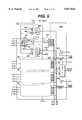
- Each image framecomprises a group of PRIs, where each PRI includes the transmission of an ultrasound wave and the reception of echoes from the body in response to the wave.
- Acquisition of an image frame or other sequence such as spectral Doppleris initiated by the receipt of data and commands from the RISC processor on RISC bus 102.
- a number of RAM addresses called “jump addresses"are stored in jump address register 104.
- Each jump addressis the starting address of a block of data in RAM 32 which is used for a specific scanning procedure.
- the jump addresses in the register 104may be updated if desired with new jump addresses provided by the RISC processor.
- a starting address for the scanning procedureis loaded into the initial address register 106, which selects one of the addresses of register 104 to be loaded into a frame address counter 108.
- the frame address counter 108sequentially reads a block of frame control data from the RAM 32 beginning with the address provided by the jump address register 104.
Landscapes
- Engineering & Computer Science (AREA)
- Physics & Mathematics (AREA)
- Radar, Positioning & Navigation (AREA)
- Remote Sensing (AREA)
- Life Sciences & Earth Sciences (AREA)
- Health & Medical Sciences (AREA)
- Acoustics & Sound (AREA)
- Computer Networks & Wireless Communication (AREA)
- General Physics & Mathematics (AREA)
- Pathology (AREA)
- Surgery (AREA)
- Nuclear Medicine, Radiotherapy & Molecular Imaging (AREA)
- Veterinary Medicine (AREA)
- Radiology & Medical Imaging (AREA)
- Biomedical Technology (AREA)
- Heart & Thoracic Surgery (AREA)
- Medical Informatics (AREA)
- Molecular Biology (AREA)
- Biophysics (AREA)
- Animal Behavior & Ethology (AREA)
- General Health & Medical Sciences (AREA)
- Public Health (AREA)
- Multimedia (AREA)
- Computer Vision & Pattern Recognition (AREA)
- Ultra Sonic Daignosis Equipment (AREA)
- Investigating Or Analyzing Materials By The Use Of Ultrasonic Waves (AREA)
Abstract
Description
TABLE 1 ______________________________________ Bits Name Function ______________________________________ 0 PRIRSTN PRI reset 1 RDEN Receive delay enable 2 SOEN Shift out enable 3 TDEN Transmit delay enable 4 TGCRSTN TGC reset 5 SERLDSerial bus load 6 RFDEN RD data enable 7 RFDVALN RF data valid 8 RFZVALN RF zone valid 9 EOLN End ofline 10 ADDSQEN Address sequencer enable 11 TGCSQEN TGC sequencer enable 12 LSEQPIN1Line sequencer pin 1 13 LSEQPIN2Line sequencer pin 2 14 TX.sub.-- ON Trans./rec. switch control 15 -- unused ______________________________________
Claims (28)
Priority Applications (27)
| Application Number | Priority Date | Filing Date | Title |
|---|---|---|---|
| US08/863,937US5817024A (en) | 1996-06-28 | 1997-05-27 | Hand held ultrasonic diagnostic instrument with digital beamformer |
| BR9801670ABR9801670A (en) | 1997-05-27 | 1998-05-20 | Portable ultrasonic diagnostic instrument with digital beam former |
| AU68099/98AAU730822B2 (en) | 1997-05-27 | 1998-05-25 | Hand held ultrasonic diagnostic instrument with digital beamformer |
| ES98304152TES2251057T3 (en) | 1997-05-27 | 1998-05-26 | ULTRASONIC DEVICE OF HAND DIAGNOISTICS WITH DIGITAL BEAM FORMING UNIT. |
| AT98304152TATE305654T1 (en) | 1997-05-27 | 1998-05-26 | PORTABLE ULTRASONIC DIAGNOSTIC DEVICE WITH A DIGITAL BEAM SHAPER |
| DE69831698TDE69831698T2 (en) | 1997-05-27 | 1998-05-26 | Portable ultrasound diagnostic device with a digital beamformer |
| EP98304152AEP0881492B1 (en) | 1997-05-27 | 1998-05-26 | Hand held ultrasonic diagnostic instrument with digital beamformer |
| CNB981089739ACN1231183C (en) | 1997-05-27 | 1998-05-26 | Hand held ultrasonic diagnostic instrument with digital beamformer |
| NO19982389ANO326202B1 (en) | 1997-05-27 | 1998-05-26 | Handheld ultrasonic device with digital beam shaping |
| KR1019980019208AKR19980087413A (en) | 1997-05-27 | 1998-05-27 | Portable Ultrasound Diagnostic Device with Digital Beam Former |
| JP10146373AJPH1156838A (en) | 1997-05-27 | 1998-05-27 | Portable ultrasonic system, image processor and integrated circuit therefor |
| US09/167,964US6135961A (en) | 1996-06-28 | 1998-10-06 | Ultrasonic signal processor for a hand held ultrasonic diagnostic instrument |
| US09/426,088US6383139B1 (en) | 1996-06-28 | 1999-10-22 | Ultrasonic signal processor for power doppler imaging in a hand held ultrasonic diagnostic instrument |
| US09/630,165US6416475B1 (en) | 1996-06-28 | 2000-08-01 | Ultrasonic signal processor for a hand held ultrasonic diagnostic instrument |
| US10/099,474US7819807B2 (en) | 1996-06-28 | 2002-03-15 | Balance body ultrasound system |
| US10/151,583US20020177774A1 (en) | 1996-06-28 | 2002-05-16 | Ultrasonic signal processor for a hand held ultrasonic diagnostic instrument |
| US10/227,160US6575908B2 (en) | 1996-06-28 | 2002-08-21 | Balance body ultrasound system |
| US10/404,220US8435183B2 (en) | 1996-06-28 | 2003-03-31 | Balance body ultrasound system |
| US10/745,827US7604596B2 (en) | 1996-06-28 | 2003-12-24 | Ultrasonic signal processor for a hand held ultrasonic diagnostic instrument |
| US11/762,019US7740586B2 (en) | 1996-06-28 | 2007-06-12 | Ultrasonic signal processor for a hand held ultrasonic diagnostic instrument |
| US12/692,483US8216146B2 (en) | 1996-06-28 | 2010-01-22 | Ultrasonic signal processor for a hand held ultrasonic diagnostic instrument |
| US12/771,982US8052606B2 (en) | 1996-06-28 | 2010-04-30 | Balance body ultrasound system |
| US13/290,883US20120289829A1 (en) | 1996-06-28 | 2011-11-07 | Balance body ultrasound system |
| US13/491,602US20120243367A1 (en) | 1996-06-28 | 2012-06-08 | Ultrasonic Signal Processor for a Hand Held Ultrasonic Diagnostic Instrument |
| US13/786,379US20130245449A1 (en) | 1996-06-28 | 2013-03-05 | Balance body ultrasound system |
| US13/857,122US20130331694A1 (en) | 1996-06-28 | 2013-04-04 | Balance body ultrasound system |
| US14/177,142US20140155752A1 (en) | 1996-06-28 | 2014-02-10 | Ultrasonic signal processor for a hand held ultrasonic diagnostic instrument |
Applications Claiming Priority (2)
| Application Number | Priority Date | Filing Date | Title |
|---|---|---|---|
| US08/672,782US5722412A (en) | 1996-06-28 | 1996-06-28 | Hand held ultrasonic diagnostic instrument |
| US08/863,937US5817024A (en) | 1996-06-28 | 1997-05-27 | Hand held ultrasonic diagnostic instrument with digital beamformer |
Related Parent Applications (2)
| Application Number | Title | Priority Date | Filing Date |
|---|---|---|---|
| US08/672,782Continuation-In-PartUS5722412A (en) | 1996-06-28 | 1996-06-28 | Hand held ultrasonic diagnostic instrument |
| US08/826,543Continuation-In-PartUS5893363A (en) | 1996-06-28 | 1997-04-03 | Ultrasonic array transducer transceiver for a hand held ultrasonic diagnostic instrument |
Related Child Applications (3)
| Application Number | Title | Priority Date | Filing Date |
|---|---|---|---|
| US08/826,543Continuation-In-PartUS5893363A (en) | 1996-06-28 | 1997-04-03 | Ultrasonic array transducer transceiver for a hand held ultrasonic diagnostic instrument |
| US09/167,964Continuation-In-PartUS6135961A (en) | 1996-06-28 | 1998-10-06 | Ultrasonic signal processor for a hand held ultrasonic diagnostic instrument |
| US10/099,474Continuation-In-PartUS7819807B2 (en) | 1996-06-28 | 2002-03-15 | Balance body ultrasound system |
Publications (1)
| Publication Number | Publication Date |
|---|---|
| US5817024Atrue US5817024A (en) | 1998-10-06 |
Family
ID=25342151
Family Applications (1)
| Application Number | Title | Priority Date | Filing Date |
|---|---|---|---|
| US08/863,937Expired - LifetimeUS5817024A (en) | 1996-06-28 | 1997-05-27 | Hand held ultrasonic diagnostic instrument with digital beamformer |
Country Status (11)
| Country | Link |
|---|---|
| US (1) | US5817024A (en) |
| EP (1) | EP0881492B1 (en) |
| JP (1) | JPH1156838A (en) |
| KR (1) | KR19980087413A (en) |
| CN (1) | CN1231183C (en) |
| AT (1) | ATE305654T1 (en) |
| AU (1) | AU730822B2 (en) |
| BR (1) | BR9801670A (en) |
| DE (1) | DE69831698T2 (en) |
| ES (1) | ES2251057T3 (en) |
| NO (1) | NO326202B1 (en) |
Cited By (188)
| Publication number | Priority date | Publication date | Assignee | Title |
|---|---|---|---|---|
| EP0919809A1 (en)* | 1997-11-25 | 1999-06-02 | BETRIEBSFORSCHUNGSINSTITUT VDEh, INSTITUT FÜR ANGEWANDTE FORSCHUNG GmbH | Transmission system for ultrasonic waves |
| US5924993A (en)* | 1997-10-15 | 1999-07-20 | Advanced Coronary Intervention, Inc. | Intravascular ultrasound mixed signal multiplexer/pre-amplifier asic |
| US5970025A (en)* | 1998-06-10 | 1999-10-19 | Acuson Corporation | Ultrasound beamformation integrated circuit and method |
| WO2000019905A1 (en)* | 1998-10-06 | 2000-04-13 | Sonosite, Inc. | Hand held ultrasonic diagnostic instrument |
| US6102863A (en)* | 1998-11-20 | 2000-08-15 | Atl Ultrasound | Ultrasonic diagnostic imaging system with thin cable ultrasonic probes |
| US6106468A (en)* | 1999-04-05 | 2000-08-22 | Agilent Technologies, Inc. | Ultrasound system employing a unified memory |
| US6106472A (en)* | 1995-06-29 | 2000-08-22 | Teratech Corporation | Portable ultrasound imaging system |
| US6126608A (en)* | 1999-05-18 | 2000-10-03 | Pie Medical Equipment B.V. | Portable ultrasound diagnostic system with handsfree display |
| WO2000066001A1 (en)* | 1999-05-05 | 2000-11-09 | Sonosite, Inc. | Low power portable ultrasonic diagnostic instrument |
| WO2001013796A1 (en)* | 1999-08-20 | 2001-03-01 | Novasonics, Inc. | Miniaturized ultrasound apparatus and method |
| US6203498B1 (en) | 1996-06-28 | 2001-03-20 | Sonosite, Inc. | Ultrasonic imaging device with integral display |
| US6315731B1 (en)* | 1999-03-31 | 2001-11-13 | Olympus Optical Co., Ltd. | Ultrasonic diagnostic apparatus capable of functional addition |
| US6361497B1 (en)* | 1998-10-06 | 2002-03-26 | Scimed Life Systems, Inc. | Control panel for intravascular ultrasonic imaging system |
| US6379304B1 (en) | 1995-06-29 | 2002-04-30 | Teratech Corporation | Ultrasound scan conversion with spatial dithering |
| US6416475B1 (en) | 1996-06-28 | 2002-07-09 | Sonosite, Inc. | Ultrasonic signal processor for a hand held ultrasonic diagnostic instrument |
| US6436040B1 (en) | 2000-11-09 | 2002-08-20 | Koninklijke Philips Electronics N.V. | Intuitive user interface and control circuitry including linear distance measurement and user localization in a portable ultrasound diagnostic device |
| US6440076B1 (en) | 2000-11-09 | 2002-08-27 | Koninklijke Philips Electronics N.V. | Ultrasound transducer connector assembly |
| USD462446S1 (en) | 2001-09-19 | 2002-09-03 | Novasonics, Inc. | Handheld ultrasonic transducer with bulb grip |
| US6471649B1 (en) | 2000-11-09 | 2002-10-29 | Koninklijke Philips Electronics N.V. | Method and apparatus for storing image information in an ultrasound device |
| US6485421B2 (en)* | 2000-09-07 | 2002-11-26 | Ge Medical Systems Global Technology Company, Llc | Ultrasonic imaging system and display device |
| US6491630B1 (en) | 2000-11-09 | 2002-12-10 | Koninklijke Philips Electronics N.V. | Ultrasound imaging device having a soft keyboard for entering data |
| USD467002S1 (en) | 2001-09-19 | 2002-12-10 | Novasonics, Inc. | Handheld ultrasonic transducer with curved bulb grip |
| US20030004414A1 (en)* | 2001-05-31 | 2003-01-02 | Mclaughlin Glen | System and method for phase inversion ultrasonic imaging |
| US20030013966A1 (en)* | 1996-06-28 | 2003-01-16 | Sonosite, Inc. | Balance body ultrasound system |
| USD469539S1 (en) | 2001-08-31 | 2003-01-28 | Novasonics, Inc. | Handheld ultrasonic display device |
| USD469877S1 (en) | 2001-08-31 | 2003-02-04 | Novasonics, Inc. | Handheld ultrasonic display device with cover |
| US20030028341A1 (en)* | 2001-07-31 | 2003-02-06 | Fallon Joseph R. | Power on self test (POST) and extended self test (EST) for ultrasonic imaging system |
| US6530887B1 (en) | 1996-12-24 | 2003-03-11 | Teratech Corporation | Ultrasound probe with integrated electronics |
| US6542846B1 (en) | 2000-11-09 | 2003-04-01 | Koninklijke Philips Electronics N.V. | Thermal management system for a portable ultrasound imaging device |
| US6540685B1 (en) | 2000-11-09 | 2003-04-01 | Koninklijke Philips Electronics N.V. | Ultrasound diagnostic device |
| US6540682B1 (en) | 2000-11-09 | 2003-04-01 | Koninklijke Philips Electronics N.V. | Portable, configurable and scalable ultrasound imaging system |
| US20030078497A1 (en)* | 2001-10-20 | 2003-04-24 | Ting-Lan Ji | Simultaneous multi-mode and multi-band ultrasonic imaging |
| US6575908B2 (en) | 1996-06-28 | 2003-06-10 | Sonosite, Inc. | Balance body ultrasound system |
| US20030139671A1 (en)* | 2002-01-17 | 2003-07-24 | Siemens Medical Solutions Usa, Inc. | Immersive portable ultrasound system and method |
| US6600446B2 (en) | 2001-06-29 | 2003-07-29 | Lockheed Martin Corporation | Cascadable architecture for digital beamformer |
| US6618206B2 (en) | 2001-10-20 | 2003-09-09 | Zonare Medical Systems, Inc. | System and method for acoustic imaging at two focal lengths with a single lens |
| US6635019B2 (en) | 2001-08-14 | 2003-10-21 | Koninklijke Philips Electronics Nv | Scanhead assembly for ultrasonic imaging having an integral beamformer and demountable array |
| US20030225940A1 (en)* | 2002-05-29 | 2003-12-04 | Oliver Daigle | System and method for acquiring data in a processing unit |
| US6663567B2 (en) | 2002-03-19 | 2003-12-16 | Zonare Medical Systems, Inc. | System and method for post-processing ultrasound color doppler imaging |
| US6669633B2 (en) | 1999-06-22 | 2003-12-30 | Teratech Corporation | Unitary operator control for ultrasonic imaging graphical user interface |
| US20040015079A1 (en)* | 1999-06-22 | 2004-01-22 | Teratech Corporation | Ultrasound probe with integrated electronics |
| US20040019278A1 (en)* | 2000-05-26 | 2004-01-29 | Kenneth Abend | Device and method for mapping and tracking blood flow and determining parameters of blood flow |
| US20040116952A1 (en)* | 1999-03-05 | 2004-06-17 | Olympus Optical Co., Ltd. | Surgical apparatus permitting recharge of battery-driven surgical instrument in noncontact state |
| US20040138569A1 (en)* | 1999-08-20 | 2004-07-15 | Sorin Grunwald | User interface for handheld imaging devices |
| US20040147841A1 (en)* | 1999-08-20 | 2004-07-29 | Mclaughlin Glen | Broad-beam imaging methods |
| WO2004064619A2 (en) | 2003-01-14 | 2004-08-05 | University Of Virginia Patent Foundation | Ultrasound imaging beam-former apparatus and method |
| US6773399B2 (en) | 2001-10-20 | 2004-08-10 | Zonare Medical Systems, Inc. | Block-switching in ultrasound imaging |
| US20040158154A1 (en)* | 2003-02-06 | 2004-08-12 | Siemens Medical Solutions Usa, Inc. | Portable three dimensional diagnostic ultrasound imaging methods and systems |
| US6780154B2 (en) | 2002-01-17 | 2004-08-24 | Siemens Medical Solutions Usa, Inc. | Segmented handheld medical ultrasound system and method |
| US6814702B2 (en) | 1997-09-09 | 2004-11-09 | Neutrino Development Corporation | Apparatus for measuring hemodynamic parameters |
| US20040247043A1 (en)* | 1999-07-28 | 2004-12-09 | Matsushita Electric Industrial Co., Ltd. | Transmission apparatus, reception apparatus and digital radio communication method |
| US20040267127A1 (en)* | 1999-05-28 | 2004-12-30 | Vuesonix Sensors, Inc. | Transmitter patterns for multi beam reception |
| US20050004461A1 (en)* | 1999-05-28 | 2005-01-06 | Kenneth Abend | Pulse interleaving in doppler ultrasound imaging |
| US20050054929A1 (en)* | 2003-09-02 | 2005-03-10 | Angelsen Bjorn A.J. | Ultrasound imaging with syntheric receive aperture and wide aperture, focused transmit beam |
| US20050096545A1 (en)* | 2003-10-30 | 2005-05-05 | Haider Bruno H. | Methods and apparatus for transducer probe |
| US20050102009A1 (en)* | 2003-07-31 | 2005-05-12 | Peter Costantino | Ultrasound treatment and imaging system |
| US20050113699A1 (en)* | 2003-11-21 | 2005-05-26 | Haugen Geir U. | Ultrasound probe sub-aperture processing |
| US20050113698A1 (en)* | 2003-11-21 | 2005-05-26 | Kjell Kristoffersen | Ultrasound probe transceiver circuitry |
| US20050113694A1 (en)* | 2003-11-21 | 2005-05-26 | Haugen Geir U. | Ultrasound probe distributed beamformer |
| US20050124885A1 (en)* | 2003-10-29 | 2005-06-09 | Vuesonix Sensors, Inc. | Method and apparatus for determining an ultrasound fluid flow centerline |
| US20050124890A1 (en)* | 2001-11-21 | 2005-06-09 | Ge Medical Systems Global Technology Company, Llc | Method and system for PDA-based ultrasound |
| US20050131302A1 (en)* | 2003-12-16 | 2005-06-16 | Poland Mckee D. | Ultrasonic probe having a selector switch |
| US20050148873A1 (en)* | 2003-12-19 | 2005-07-07 | Siemens Medical Solutions Usa, Inc. | Ultrasound adaptor methods and systems for transducer and system separation |
| US20050148878A1 (en)* | 2003-12-19 | 2005-07-07 | Siemens Medical Solutions Usa, Inc.. | Probe based digitizing or compression system and method for medical ultrasound |
| US6936008B2 (en) | 1999-08-20 | 2005-08-30 | Zonare Medical Systems, Inc. | Ultrasound system with cableless coupling assembly |
| US20050203404A1 (en)* | 2004-02-26 | 2005-09-15 | Siemens Medical Solutions Usa, Inc. | Steered continuous wave doppler methods and systems for two-dimensional ultrasound transducer arrays |
| US20050203391A1 (en)* | 2004-02-26 | 2005-09-15 | Siemens Medical Solutions Usa, Inc. | Element mapping and transmitter for continuous wave ultrasound imaging |
| USD510625S1 (en)* | 2004-01-21 | 2005-10-11 | Sicel Technologies, Inc. | Portable oncologic external dosimeter reader |
| US20050228287A1 (en)* | 2004-04-08 | 2005-10-13 | Sonosite, Inc. | Systems and methods providing ASICs for use in multiple applications |
| US6969352B2 (en) | 1999-06-22 | 2005-11-29 | Teratech Corporation | Ultrasound probe with integrated electronics |
| WO2004084341A3 (en)* | 2003-03-14 | 2006-02-02 | Vuesonix Sensors Inc | Method and apparatus for forming multiple beams |
| WO2005099580A3 (en)* | 2004-04-19 | 2006-04-06 | Koninkl Philips Electronics Nv | Data visualization method for an ultrasound imaging system |
| US20060100520A1 (en)* | 1999-08-20 | 2006-05-11 | Mo Larry Y L | Ultrasound system with iterative high pass filter selection |
| US20060264746A1 (en)* | 2003-05-27 | 2006-11-23 | Koninklijke Philips Electronics N.V. | Diagnostic imaging system control with multiple control functions |
| US20070016044A1 (en)* | 2003-01-14 | 2007-01-18 | University Of Virginia Patent Foundation | Ultrasonic transducer drive |
| US20070161904A1 (en)* | 2006-11-10 | 2007-07-12 | Penrith Corporation | Transducer array imaging system |
| US20070183429A1 (en)* | 2003-06-02 | 2007-08-09 | Yang Woo Y | Aalo cell format of an atm protocol for communicating voice traffic in a cdma system |
| US20080009739A1 (en)* | 2006-06-23 | 2008-01-10 | Chiang Alice M | Ultrasound 3D imaging system |
| US20080021322A1 (en)* | 2006-05-24 | 2008-01-24 | Michael Benjamin Stone | Ultrasonic imaging apparatus and method |
| US20080033293A1 (en)* | 2006-05-08 | 2008-02-07 | C. R. Bard, Inc. | User interface and methods for sonographic display device |
| US20080114249A1 (en)* | 2006-11-10 | 2008-05-15 | Penrith Corporation | Transducer array imaging system |
| US20080114241A1 (en)* | 2006-11-10 | 2008-05-15 | Penrith Corporation | Transducer array imaging system |
| US20080114239A1 (en)* | 2006-11-10 | 2008-05-15 | Penrith Corporation | Transducer array imaging system |
| US20080114251A1 (en)* | 2006-11-10 | 2008-05-15 | Penrith Corporation | Transducer array imaging system |
| US20080110266A1 (en)* | 2006-11-10 | 2008-05-15 | Penrith Corporation | Transducer array imaging system |
| US20080114247A1 (en)* | 2006-11-10 | 2008-05-15 | Penrith Corporation | Transducer array imaging system |
| US20080114255A1 (en)* | 2006-11-10 | 2008-05-15 | Penrith Corporation | Transducer array imaging system |
| US20080110261A1 (en)* | 2006-11-10 | 2008-05-15 | Penrith Corporation | Transducer array imaging system |
| US20080114245A1 (en)* | 2006-11-10 | 2008-05-15 | Randall Kevin S | Transducer array imaging system |
| US20080112265A1 (en)* | 2006-11-10 | 2008-05-15 | Penrith Corporation | Transducer array imaging system |
| US20080194964A1 (en)* | 2007-02-08 | 2008-08-14 | Randall Kevin S | Ultrasound imaging systems |
| US20080194963A1 (en)* | 2007-02-08 | 2008-08-14 | Randall Kevin S | Probes for ultrasound imaging systems |
| US20080194960A1 (en)* | 2007-02-08 | 2008-08-14 | Randall Kevin S | Probes for ultrasound imaging systems |
| US20080194961A1 (en)* | 2007-02-08 | 2008-08-14 | Randall Kevin S | Probes for ultrasound imaging systems |
| US20080194962A1 (en)* | 2007-02-08 | 2008-08-14 | Randall Kevin S | Methods for verifying the integrity of probes for ultrasound imaging systems |
| US20080255451A1 (en)* | 2007-04-10 | 2008-10-16 | C.R. Bard, Inc. | Low power ultrasound system |
| US20080281206A1 (en)* | 2005-11-07 | 2008-11-13 | Stewart Gavin Bartlett | Ultrasound Measurement System and Method |
| US20080304729A1 (en)* | 2005-04-25 | 2008-12-11 | Koninklijke Philips Electronics, N.V. | Method and Apparatus for Continuous Imaging by Ultrasound Transducer System |
| US20080314530A1 (en)* | 2007-06-22 | 2008-12-25 | Li-Ming Cheng | Window coverings |
| US20090018443A1 (en)* | 2007-07-12 | 2009-01-15 | Colby Brian V | System for generating multiple beams from a single receive event |
| US20090043204A1 (en)* | 2007-08-10 | 2009-02-12 | Laurent Pelissier | Hand-held ultrasound imaging device having removable transducer arrays |
| US20090043199A1 (en)* | 2007-08-10 | 2009-02-12 | Laurent Pelissier | Wireless network having portable ultrasound devices |
| US20090043203A1 (en)* | 2007-08-10 | 2009-02-12 | Laurent Pelissier | Power management in portable ultrasound devices |
| US20090043205A1 (en)* | 2007-08-10 | 2009-02-12 | Laurent Pelissier | Hand-held ultrasound system having sterile enclosure |
| US7502278B1 (en)* | 2006-05-23 | 2009-03-10 | Maxim Integrated Products, Inc. | Analog beamformers for continuous wave ultrasonic receivers |
| US7500952B1 (en) | 1995-06-29 | 2009-03-10 | Teratech Corporation | Portable ultrasound imaging system |
| US20090093719A1 (en)* | 2007-10-03 | 2009-04-09 | Laurent Pelissier | Handheld ultrasound imaging systems |
| US20090171215A1 (en)* | 2007-12-26 | 2009-07-02 | Sei Kato | Ultrasonic imaging apparatus |
| US20090198132A1 (en)* | 2007-08-10 | 2009-08-06 | Laurent Pelissier | Hand-held ultrasound imaging device having reconfigurable user interface |
| US20100049051A1 (en)* | 2008-04-11 | 2010-02-25 | Myung Hee Sang | Providing Hospital Information In A Portable Ultrasound System |
| US7686766B2 (en) | 2001-04-19 | 2010-03-30 | Sonosite, Inc. | Medical diagnostic ultrasound instrument with ECG module, authorization mechanism and methods of use |
| US20100174194A1 (en)* | 2008-09-15 | 2010-07-08 | Teratech Corporation | Ultrasound 3d imaging system |
| US20100228130A1 (en)* | 2009-03-09 | 2010-09-09 | Teratech Corporation | Portable ultrasound imaging system |
| US20110060225A1 (en)* | 2009-09-09 | 2011-03-10 | General Electric Company | Ultrasound probe with integrated pulsers |
| US20110224552A1 (en)* | 2008-12-03 | 2011-09-15 | Koninklijke Philips Electronics N.V. | Ultrasound assembly and system comprising interchangable transducers and displays |
| US8066642B1 (en)* | 2005-05-03 | 2011-11-29 | Sonosite, Inc. | Systems and methods for ultrasound beam forming data control |
| US8220334B2 (en) | 2006-11-10 | 2012-07-17 | Penrith Corporation | Transducer array imaging system |
| US8241217B2 (en) | 1995-06-29 | 2012-08-14 | Teratech Corporation | Portable ultrasound imaging data |
| CN102706958A (en)* | 2005-10-14 | 2012-10-03 | 奥林巴斯Ndt公司 | Ultrasonic fault detection system |
| US8388541B2 (en) | 2007-11-26 | 2013-03-05 | C. R. Bard, Inc. | Integrated system for intravascular placement of a catheter |
| US8388546B2 (en) | 2006-10-23 | 2013-03-05 | Bard Access Systems, Inc. | Method of locating the tip of a central venous catheter |
| US8437833B2 (en) | 2008-10-07 | 2013-05-07 | Bard Access Systems, Inc. | Percutaneous magnetic gastrostomy |
| US8439840B1 (en) | 2010-05-04 | 2013-05-14 | Sonosite, Inc. | Ultrasound imaging system and method with automatic adjustment and/or multiple sample volumes |
| US8469893B2 (en) | 1995-06-29 | 2013-06-25 | Teratech Corp. | Portable ultrasound imaging system |
| US8478382B2 (en) | 2008-02-11 | 2013-07-02 | C. R. Bard, Inc. | Systems and methods for positioning a catheter |
| US8490489B2 (en) | 2006-11-10 | 2013-07-23 | Siemens Medical Solutions Usa, Inc. | Transducer array imaging system |
| US8499634B2 (en) | 2006-11-10 | 2013-08-06 | Siemens Medical Solutions Usa, Inc. | Transducer array imaging system |
| US8512256B2 (en) | 2006-10-23 | 2013-08-20 | Bard Access Systems, Inc. | Method of locating the tip of a central venous catheter |
| US8568319B1 (en) | 2010-02-11 | 2013-10-29 | Mitchell Kaplan | Ultrasound imaging system apparatus and method with ADC saturation monitor |
| USD699359S1 (en) | 2011-08-09 | 2014-02-11 | C. R. Bard, Inc. | Ultrasound probe head |
| US8781555B2 (en) | 2007-11-26 | 2014-07-15 | C. R. Bard, Inc. | System for placement of a catheter including a signal-generating stylet |
| US8784336B2 (en) | 2005-08-24 | 2014-07-22 | C. R. Bard, Inc. | Stylet apparatuses and methods of manufacture |
| US8801693B2 (en) | 2010-10-29 | 2014-08-12 | C. R. Bard, Inc. | Bioimpedance-assisted placement of a medical device |
| US8849382B2 (en) | 2007-11-26 | 2014-09-30 | C. R. Bard, Inc. | Apparatus and display methods relating to intravascular placement of a catheter |
| US20150043309A1 (en)* | 2013-08-09 | 2015-02-12 | Symbol Technologies, Inc. | Ultrasonic locationing using flight time calculated from counter offsets |
| USD724745S1 (en) | 2011-08-09 | 2015-03-17 | C. R. Bard, Inc. | Cap for an ultrasound probe |
| JP2015131031A (en)* | 2014-01-14 | 2015-07-23 | 株式会社東芝 | Ultrasonic probe and ultrasonic diagnostic apparatus |
| US9125578B2 (en) | 2009-06-12 | 2015-09-08 | Bard Access Systems, Inc. | Apparatus and method for catheter navigation and tip location |
| US9211107B2 (en) | 2011-11-07 | 2015-12-15 | C. R. Bard, Inc. | Ruggedized ultrasound hydrogel insert |
| US9211110B2 (en) | 2013-03-15 | 2015-12-15 | The Regents Of The University Of Michigan | Lung ventillation measurements using ultrasound |
| US9229097B2 (en) | 2014-04-18 | 2016-01-05 | Butterfly Network, Inc. | Architecture of single substrate ultrasonic imaging devices, related apparatuses, and methods |
| US9239375B2 (en) | 2013-05-08 | 2016-01-19 | General Electric Company | Ultrasound probe with dynamic focus and associated systems and methods |
| US9254118B2 (en) | 2013-03-15 | 2016-02-09 | Analogic Corporation | Floating transducer drive, system employing the same and method of operating |
| US9327142B2 (en) | 2013-03-15 | 2016-05-03 | Butterfly Network, Inc. | Monolithic ultrasonic imaging devices, systems and methods |
| US9339206B2 (en) | 2009-06-12 | 2016-05-17 | Bard Access Systems, Inc. | Adaptor for endovascular electrocardiography |
| US9339253B2 (en) | 2005-04-25 | 2016-05-17 | Koninklijke Philips Electronics N.V. | Ultrasound probe having a disinfection status indicator |
| US9351706B2 (en) | 2013-07-23 | 2016-05-31 | Butterfly Network, Inc. | Interconnectable ultrasound transducer probes and related methods and apparatus |
| US9402601B1 (en)* | 1999-06-22 | 2016-08-02 | Teratech Corporation | Methods for controlling an ultrasound imaging procedure and providing ultrasound images to an external non-ultrasound application via a network |
| US9445734B2 (en) | 2009-06-12 | 2016-09-20 | Bard Access Systems, Inc. | Devices and methods for endovascular electrography |
| US9456766B2 (en) | 2007-11-26 | 2016-10-04 | C. R. Bard, Inc. | Apparatus for use with needle insertion guidance system |
| US9492097B2 (en) | 2007-11-26 | 2016-11-15 | C. R. Bard, Inc. | Needle length determination and calibration for insertion guidance system |
| US9521961B2 (en) | 2007-11-26 | 2016-12-20 | C. R. Bard, Inc. | Systems and methods for guiding a medical instrument |
| US9532724B2 (en) | 2009-06-12 | 2017-01-03 | Bard Access Systems, Inc. | Apparatus and method for catheter navigation using endovascular energy mapping |
| US9554716B2 (en) | 2007-11-26 | 2017-01-31 | C. R. Bard, Inc. | Insertion guidance system for needles and medical components |
| US9592032B2 (en) | 2014-04-18 | 2017-03-14 | Butterfly Network, Inc. | Ultrasonic imaging compression methods and apparatus |
| US9636031B2 (en) | 2007-11-26 | 2017-05-02 | C.R. Bard, Inc. | Stylets for use with apparatus for intravascular placement of a catheter |
| US9649048B2 (en) | 2007-11-26 | 2017-05-16 | C. R. Bard, Inc. | Systems and methods for breaching a sterile field for intravascular placement of a catheter |
| US9667889B2 (en) | 2013-04-03 | 2017-05-30 | Butterfly Network, Inc. | Portable electronic devices with integrated imaging capabilities |
| WO2017106834A1 (en) | 2015-12-18 | 2017-06-22 | Ursus Medical, Llc | Ultrasound beamforming system and method with reconfigurable aperture |
| US9839372B2 (en) | 2014-02-06 | 2017-12-12 | C. R. Bard, Inc. | Systems and methods for guidance and placement of an intravascular device |
| US9901714B2 (en) | 2008-08-22 | 2018-02-27 | C. R. Bard, Inc. | Catheter assembly including ECG sensor and magnetic assemblies |
| US9980700B2 (en) | 2011-07-22 | 2018-05-29 | Sound Technology, Inc. | Ultrasound apparatus cover |
| US10046139B2 (en) | 2010-08-20 | 2018-08-14 | C. R. Bard, Inc. | Reconfirmation of ECG-assisted catheter tip placement |
| WO2018236683A1 (en)* | 2017-06-19 | 2018-12-27 | Butterfly Network, Inc. | DIGITAL BASED DIGITAL BEAM MICROFORMATION FOR ULTRASONIC APPLICATIONS |
| WO2019094424A1 (en)* | 2017-11-13 | 2019-05-16 | Edwards Lifesciences Corporation | Non-invasive heart valve screening device and method |
| US10349890B2 (en) | 2015-06-26 | 2019-07-16 | C. R. Bard, Inc. | Connector interface for ECG-based catheter positioning system |
| US10405829B2 (en) | 2014-12-01 | 2019-09-10 | Clarius Mobile Health Corp. | Ultrasound machine having scalable receive beamformer architecture comprising multiple beamformers with common coefficient generator and related methods |
| US10413279B2 (en) | 2011-10-28 | 2019-09-17 | Beijing East Whale Image Technology Co., Ltd. | Color ultrasound system and method and device thereof for obtaining beam-forming line data |
| US10426435B2 (en) | 2008-09-15 | 2019-10-01 | Teratech Corporation | Ultrasound 3D imaging system |
| US10449330B2 (en) | 2007-11-26 | 2019-10-22 | C. R. Bard, Inc. | Magnetic element-equipped needle assemblies |
| US10469846B2 (en) | 2017-03-27 | 2019-11-05 | Vave Health, Inc. | Dynamic range compression of ultrasound images |
| US10524691B2 (en) | 2007-11-26 | 2020-01-07 | C. R. Bard, Inc. | Needle assembly including an aligned magnetic element |
| US10639008B2 (en) | 2009-10-08 | 2020-05-05 | C. R. Bard, Inc. | Support and cover structures for an ultrasound probe head |
| US10751509B2 (en) | 2007-11-26 | 2020-08-25 | C. R. Bard, Inc. | Iconic representations for guidance of an indwelling medical device |
| US10820885B2 (en) | 2012-06-15 | 2020-11-03 | C. R. Bard, Inc. | Apparatus and methods for detection of a removable cap on an ultrasound probe |
| US10856843B2 (en) | 2017-03-23 | 2020-12-08 | Vave Health, Inc. | Flag table based beamforming in a handheld ultrasound device |
| US10945706B2 (en) | 2017-05-05 | 2021-03-16 | Biim Ultrasound As | Hand held ultrasound probe |
| US10973584B2 (en) | 2015-01-19 | 2021-04-13 | Bard Access Systems, Inc. | Device and method for vascular access |
| US10992079B2 (en) | 2018-10-16 | 2021-04-27 | Bard Access Systems, Inc. | Safety-equipped connection systems and methods thereof for establishing electrical connections |
| US11000207B2 (en) | 2016-01-29 | 2021-05-11 | C. R. Bard, Inc. | Multiple coil system for tracking a medical device |
| US11086002B1 (en)* | 2015-04-21 | 2021-08-10 | Maxim Integrated Products, Inc. | Ultrasound sub-array receiver beamformer |
| US11103213B2 (en) | 2009-10-08 | 2021-08-31 | C. R. Bard, Inc. | Spacers for use with an ultrasound probe |
| US20210286434A1 (en)* | 2020-03-02 | 2021-09-16 | Emerge Now Inc. | System and method for producing mid-air tactile stimulation |
| CN113826025A (en)* | 2019-05-14 | 2021-12-21 | 皇家飞利浦有限公司 | Method and apparatus for generating shear waves |
| US11375980B2 (en) | 2017-11-15 | 2022-07-05 | Bfly Operations, Inc. | Ultrasound apparatuses and methods for fabricating ultrasound devices |
| US11446003B2 (en) | 2017-03-27 | 2022-09-20 | Vave Health, Inc. | High performance handheld ultrasound |
| US11531096B2 (en) | 2017-03-23 | 2022-12-20 | Vave Health, Inc. | High performance handheld ultrasound |
| US12102479B2 (en) | 2008-09-15 | 2024-10-01 | Teratech Corporation | Ultrasound 3D imaging system |
Families Citing this family (25)
| Publication number | Priority date | Publication date | Assignee | Title |
|---|---|---|---|---|
| JP3828744B2 (en)* | 2000-12-18 | 2006-10-04 | ジーイー・メディカル・システムズ・グローバル・テクノロジー・カンパニー・エルエルシー | Ultrasound imaging device |
| US6551248B2 (en)* | 2001-07-31 | 2003-04-22 | Koninklijke Philips Electronics N.V. | System for attaching an acoustic element to an integrated circuit |
| KR100413779B1 (en)* | 2001-08-16 | 2003-12-31 | 주식회사 이지메딕스 | Ultrasonic diagnostic imaging system |
| CN1307427C (en)* | 2002-08-28 | 2007-03-28 | 深圳迈瑞生物医疗电子股份有限公司 | Beam synthesizer and synthetic method based on linear interpolation |
| CN1938754B (en)* | 2004-04-02 | 2010-10-06 | 皇家飞利浦电子股份有限公司 | Intracavity probe with continuous shielding of acoustic window |
| CN100337595C (en)* | 2004-06-18 | 2007-09-19 | 深圳迈瑞生物医疗电子股份有限公司 | Beam composition method and device based on null aim interpolation |
| US7611463B2 (en)* | 2004-10-28 | 2009-11-03 | General Electric Company | Ultrasound beamformer with high speed serial control bus packetized protocol |
| JP2006138726A (en)* | 2004-11-11 | 2006-06-01 | Olympus Corp | Ultrasonic non-destructive inspection device |
| DK2152167T3 (en)* | 2007-05-07 | 2018-12-10 | Guided Therapy Systems Llc | Methods and systems for coupling and focusing acoustic energy using a coupling element |
| CN101449981B (en)* | 2007-11-30 | 2012-07-11 | 深圳迈瑞生物医疗电子股份有限公司 | Ultrasonic diagnostic device |
| JP5323445B2 (en)* | 2008-10-21 | 2013-10-23 | 富士フイルム株式会社 | Ultrasonic diagnostic equipment |
| JP5645421B2 (en)* | 2010-02-23 | 2014-12-24 | キヤノン株式会社 | Ultrasonic imaging apparatus and delay control method |
| CN102247162A (en)* | 2011-03-29 | 2011-11-23 | 辽宁汉德科技有限公司 | Handheld B ultrasonic diagnostic instrument for veterinary use |
| CN103377163A (en)* | 2012-04-13 | 2013-10-30 | 深圳市蓝韵实业有限公司 | Ultrasonic imaging system and real-time collected data transmission method therefor |
| KR101630761B1 (en)* | 2012-09-24 | 2016-06-15 | 삼성전자주식회사 | Ultrasound apparatus and method for providing information using the ultrasound apparatus |
| CN107773273B (en)* | 2013-11-19 | 2023-12-01 | 港大科桥有限公司 | Ultrasonic fluid vector imaging device and method thereof |
| CN104856723A (en)* | 2015-06-10 | 2015-08-26 | 苏州斯科特医学影像科技有限公司 | Ultrasonic follicle inspector |
| DE102015213990A1 (en)* | 2015-07-24 | 2017-01-26 | Robert Bosch Gmbh | Device for emitting and / or receiving acoustic signals |
| CN105167803A (en)* | 2015-10-23 | 2015-12-23 | 苏州斯科特医学影像科技有限公司 | High-array-element wireless probe interior B ultrasonic inspection method |
| WO2018041987A1 (en)* | 2016-09-02 | 2018-03-08 | Koninklijke Philips N.V. | Ultrasound probe with low frequency, low voltage digital microbeamformer |
| JP6483911B1 (en)* | 2018-11-28 | 2019-03-13 | メロディ・インターナショナル株式会社 | Ultrasonic inspection equipment |
| CN110974304B (en)* | 2019-12-13 | 2021-07-30 | 山东大学齐鲁医院 | Ultrasonic beam combining system and method based on wearable flexible ultrasonic transducer |
| CN112650707A (en)* | 2019-10-10 | 2021-04-13 | 上海科技大学 | Multichannel photoacoustic signal delay device, multichannel photoacoustic signal delay system, signal processing method, terminal and medium |
| KR102413337B1 (en)* | 2020-06-08 | 2022-06-28 | 충북대학교병원 | Portable scanning probe with monitor |
| CN116829984A (en) | 2022-01-06 | 2023-09-29 | 艾科索成像公司 | Full array digital 3D ultrasound imaging system integrated with matrix array transducer |
Citations (7)
| Publication number | Priority date | Publication date | Assignee | Title |
|---|---|---|---|---|
| US4173007A (en)* | 1977-07-01 | 1979-10-30 | G. D. Searle & Co. | Dynamically variable electronic delay lines for real time ultrasonic imaging systems |
| US5123415A (en)* | 1990-07-19 | 1992-06-23 | Advanced Technology Laboratories, Inc. | Ultrasonic imaging by radial scan of trapezoidal sector |
| US5295485A (en)* | 1991-12-13 | 1994-03-22 | Hitachi, Ltd. | Ultrasonic diagnostic system |
| US5360005A (en)* | 1992-01-10 | 1994-11-01 | Wilk Peter J | Medical diagnosis device for sensing cardiac activity and blood flow |
| US5369624A (en)* | 1993-03-26 | 1994-11-29 | Siemens Medical Systems, Inc. | Digital beamformer having multi-phase parallel processing |
| US5590658A (en)* | 1995-06-29 | 1997-01-07 | Teratech Corporation | Portable ultrasound imaging system |
| US5709209A (en)* | 1996-03-29 | 1998-01-20 | Siemens Medical Systems, Inc. | Ultrasound signal processing system |
Family Cites Families (2)
| Publication number | Priority date | Publication date | Assignee | Title |
|---|---|---|---|---|
| US4542653A (en) | 1983-11-21 | 1985-09-24 | Advanced Technology Laboratories, Inc. | Apparatus and method for beamforming in an ultrasonic transducer array |
| US5722412A (en)* | 1996-06-28 | 1998-03-03 | Advanced Technology Laboratories, Inc. | Hand held ultrasonic diagnostic instrument |
- 1997
- 1997-05-27USUS08/863,937patent/US5817024A/ennot_activeExpired - Lifetime
- 1998
- 1998-05-20BRBR9801670Apatent/BR9801670A/ennot_activeApplication Discontinuation
- 1998-05-25AUAU68099/98Apatent/AU730822B2/ennot_activeExpired
- 1998-05-26ESES98304152Tpatent/ES2251057T3/ennot_activeExpired - Lifetime
- 1998-05-26CNCNB981089739Apatent/CN1231183C/ennot_activeExpired - Lifetime
- 1998-05-26DEDE69831698Tpatent/DE69831698T2/ennot_activeExpired - Lifetime
- 1998-05-26ATAT98304152Tpatent/ATE305654T1/ennot_activeIP Right Cessation
- 1998-05-26NONO19982389Apatent/NO326202B1/ennot_activeIP Right Cessation
- 1998-05-26EPEP98304152Apatent/EP0881492B1/ennot_activeExpired - Lifetime
- 1998-05-27JPJP10146373Apatent/JPH1156838A/enactivePending
- 1998-05-27KRKR1019980019208Apatent/KR19980087413A/ennot_activeCeased
Patent Citations (8)
| Publication number | Priority date | Publication date | Assignee | Title |
|---|---|---|---|---|
| US4173007A (en)* | 1977-07-01 | 1979-10-30 | G. D. Searle & Co. | Dynamically variable electronic delay lines for real time ultrasonic imaging systems |
| US5123415A (en)* | 1990-07-19 | 1992-06-23 | Advanced Technology Laboratories, Inc. | Ultrasonic imaging by radial scan of trapezoidal sector |
| US5295485A (en)* | 1991-12-13 | 1994-03-22 | Hitachi, Ltd. | Ultrasonic diagnostic system |
| US5360005A (en)* | 1992-01-10 | 1994-11-01 | Wilk Peter J | Medical diagnosis device for sensing cardiac activity and blood flow |
| US5369624A (en)* | 1993-03-26 | 1994-11-29 | Siemens Medical Systems, Inc. | Digital beamformer having multi-phase parallel processing |
| US5590658A (en)* | 1995-06-29 | 1997-01-07 | Teratech Corporation | Portable ultrasound imaging system |
| US5690114A (en)* | 1995-06-29 | 1997-11-25 | Teratech Corporation | Portable ultrasound imaging system |
| US5709209A (en)* | 1996-03-29 | 1998-01-20 | Siemens Medical Systems, Inc. | Ultrasound signal processing system |
Non-Patent Citations (3)
| Title |
|---|
| Micros Q.V. brochure by Advanced Medical Products, Inc. (Sep. 1996).* |
| Minivisor Service Manual from Organon Teknika (Sep. 1979).* |
| Ultra PCI System Specifications from Advanced Medical Products of Columbia, South Carolina (date unknown).* |
Cited By (362)
| Publication number | Priority date | Publication date | Assignee | Title |
|---|---|---|---|---|
| US20030028113A1 (en)* | 1995-06-29 | 2003-02-06 | Teratech Corporation | Ultrasound scan conversion with spatial dithering |
| US8628474B2 (en) | 1995-06-29 | 2014-01-14 | Teratech Corporation | Portable ultrasound imaging system |
| US8241217B2 (en) | 1995-06-29 | 2012-08-14 | Teratech Corporation | Portable ultrasound imaging data |
| US7500952B1 (en) | 1995-06-29 | 2009-03-10 | Teratech Corporation | Portable ultrasound imaging system |
| US6379304B1 (en) | 1995-06-29 | 2002-04-30 | Teratech Corporation | Ultrasound scan conversion with spatial dithering |
| US8469893B2 (en) | 1995-06-29 | 2013-06-25 | Teratech Corp. | Portable ultrasound imaging system |
| US6106472A (en)* | 1995-06-29 | 2000-08-22 | Teratech Corporation | Portable ultrasound imaging system |
| US6575908B2 (en) | 1996-06-28 | 2003-06-10 | Sonosite, Inc. | Balance body ultrasound system |
| US20100274131A1 (en)* | 1996-06-28 | 2010-10-28 | Sonosite, Inc. | Balance Body Ultrasound System |
| US7819807B2 (en) | 1996-06-28 | 2010-10-26 | Sonosite, Inc. | Balance body ultrasound system |
| US8435183B2 (en) | 1996-06-28 | 2013-05-07 | Sonosite, Inc. | Balance body ultrasound system |
| US6203498B1 (en) | 1996-06-28 | 2001-03-20 | Sonosite, Inc. | Ultrasonic imaging device with integral display |
| US7604596B2 (en) | 1996-06-28 | 2009-10-20 | Sonosite, Inc. | Ultrasonic signal processor for a hand held ultrasonic diagnostic instrument |
| US8052606B2 (en) | 1996-06-28 | 2011-11-08 | Sonosite, Inc. | Balance body ultrasound system |
| US6135961A (en)* | 1996-06-28 | 2000-10-24 | Sonosite, Inc. | Ultrasonic signal processor for a hand held ultrasonic diagnostic instrument |
| US20040138564A1 (en)* | 1996-06-28 | 2004-07-15 | Sonosite, Inc. | Ultrasonic signal processor for a hand held ultrasonic diagnostic instrument |
| US6416475B1 (en) | 1996-06-28 | 2002-07-09 | Sonosite, Inc. | Ultrasonic signal processor for a hand held ultrasonic diagnostic instrument |
| US20100121196A1 (en)* | 1996-06-28 | 2010-05-13 | Sonosite, Inc. | Ultrasonic Signal Processor for a Hand Held Ultrasonic Diagnostic Instrument |
| US7740586B2 (en) | 1996-06-28 | 2010-06-22 | Sonosite, Inc. | Ultrasonic signal processor for a hand held ultrasonic diagnostic instrument |
| US20030195418A1 (en)* | 1996-06-28 | 2003-10-16 | Sonosite, Inc. | Balance body ultrasound system |
| US20030013966A1 (en)* | 1996-06-28 | 2003-01-16 | Sonosite, Inc. | Balance body ultrasound system |
| US8216146B2 (en) | 1996-06-28 | 2012-07-10 | Sonosite, Inc. | Ultrasonic signal processor for a hand held ultrasonic diagnostic instrument |
| US6530887B1 (en) | 1996-12-24 | 2003-03-11 | Teratech Corporation | Ultrasound probe with integrated electronics |
| US6814702B2 (en) | 1997-09-09 | 2004-11-09 | Neutrino Development Corporation | Apparatus for measuring hemodynamic parameters |
| US20040230120A1 (en)* | 1997-09-09 | 2004-11-18 | Redano Richard T. | Apparatus for measuring hemodynamic parameters |
| US5924993A (en)* | 1997-10-15 | 1999-07-20 | Advanced Coronary Intervention, Inc. | Intravascular ultrasound mixed signal multiplexer/pre-amplifier asic |
| US6637270B1 (en) | 1997-11-25 | 2003-10-28 | Betriebsforschungsinstitut Vdeh-Institut Fur Angewandte Forschung Gmbh | System for transmitting ultrasonic waves |
| EP0919809A1 (en)* | 1997-11-25 | 1999-06-02 | BETRIEBSFORSCHUNGSINSTITUT VDEh, INSTITUT FÜR ANGEWANDTE FORSCHUNG GmbH | Transmission system for ultrasonic waves |
| US5970025A (en)* | 1998-06-10 | 1999-10-19 | Acuson Corporation | Ultrasound beamformation integrated circuit and method |
| US6361497B1 (en)* | 1998-10-06 | 2002-03-26 | Scimed Life Systems, Inc. | Control panel for intravascular ultrasonic imaging system |
| WO2000019905A1 (en)* | 1998-10-06 | 2000-04-13 | Sonosite, Inc. | Hand held ultrasonic diagnostic instrument |
| US6102863A (en)* | 1998-11-20 | 2000-08-15 | Atl Ultrasound | Ultrasonic diagnostic imaging system with thin cable ultrasonic probes |
| US20040116952A1 (en)* | 1999-03-05 | 2004-06-17 | Olympus Optical Co., Ltd. | Surgical apparatus permitting recharge of battery-driven surgical instrument in noncontact state |
| US6315731B1 (en)* | 1999-03-31 | 2001-11-13 | Olympus Optical Co., Ltd. | Ultrasonic diagnostic apparatus capable of functional addition |
| US6106468A (en)* | 1999-04-05 | 2000-08-22 | Agilent Technologies, Inc. | Ultrasound system employing a unified memory |
| WO2000066001A1 (en)* | 1999-05-05 | 2000-11-09 | Sonosite, Inc. | Low power portable ultrasonic diagnostic instrument |
| US6471651B1 (en) | 1999-05-05 | 2002-10-29 | Sonosite, Inc. | Low power portable ultrasonic diagnostic instrument |
| US6126608A (en)* | 1999-05-18 | 2000-10-03 | Pie Medical Equipment B.V. | Portable ultrasound diagnostic system with handsfree display |
| US7238158B2 (en) | 1999-05-28 | 2007-07-03 | Allez Physionix, Ltd. | Pulse interleaving in doppler ultrasound imaging |
| US20050004461A1 (en)* | 1999-05-28 | 2005-01-06 | Kenneth Abend | Pulse interleaving in doppler ultrasound imaging |
| US20040267127A1 (en)* | 1999-05-28 | 2004-12-30 | Vuesonix Sensors, Inc. | Transmitter patterns for multi beam reception |
| US20080269609A1 (en)* | 1999-05-28 | 2008-10-30 | Physiosonics, Inc. | Devices and methods for tracking blood flow and determining parameters of blood flow |
| US7399279B2 (en) | 1999-05-28 | 2008-07-15 | Physiosonics, Inc | Transmitter patterns for multi beam reception |
| US11547382B2 (en) | 1999-06-22 | 2023-01-10 | Teratech Corporation | Networked ultrasound system and method for imaging a medical procedure using an invasive probe |
| US6783493B2 (en) | 1999-06-22 | 2004-08-31 | Teratech Corporation | Ultrasound probe with integrated electronics |
| US6869401B2 (en) | 1999-06-22 | 2005-03-22 | Teratech Corporation | Ultrasound probe with integrated electronics |
| US6969352B2 (en) | 1999-06-22 | 2005-11-29 | Teratech Corporation | Ultrasound probe with integrated electronics |
| US6669633B2 (en) | 1999-06-22 | 2003-12-30 | Teratech Corporation | Unitary operator control for ultrasonic imaging graphical user interface |
| US12138128B2 (en) | 1999-06-22 | 2024-11-12 | Teratech Corporation | Ultrasound probe with integrated electronics |
| US20040015079A1 (en)* | 1999-06-22 | 2004-01-22 | Teratech Corporation | Ultrasound probe with integrated electronics |
| US9402601B1 (en)* | 1999-06-22 | 2016-08-02 | Teratech Corporation | Methods for controlling an ultrasound imaging procedure and providing ultrasound images to an external non-ultrasound application via a network |
| US20030176787A1 (en)* | 1999-06-22 | 2003-09-18 | Teratech Corporation | Ultrasound probe with integrated electronics |
| US20040247043A1 (en)* | 1999-07-28 | 2004-12-09 | Matsushita Electric Industrial Co., Ltd. | Transmission apparatus, reception apparatus and digital radio communication method |
| US20030220573A1 (en)* | 1999-08-20 | 2003-11-27 | Imran Mir A. | Miniaturized ultrasound apparatus and method |
| US7238157B2 (en) | 1999-08-20 | 2007-07-03 | Zonare Medical Systems, Inc. | Broad-beam imaging methods |
| US20040147841A1 (en)* | 1999-08-20 | 2004-07-29 | Mclaughlin Glen | Broad-beam imaging methods |
| US6936008B2 (en) | 1999-08-20 | 2005-08-30 | Zonare Medical Systems, Inc. | Ultrasound system with cableless coupling assembly |
| US7022075B2 (en) | 1999-08-20 | 2006-04-04 | Zonare Medical Systems, Inc. | User interface for handheld imaging devices |
| US8226561B2 (en) | 1999-08-20 | 2012-07-24 | Zonare Medical Systems, Inc. | Ultrasound imaging system |
| US20060036178A1 (en)* | 1999-08-20 | 2006-02-16 | Umit Tarakci | Cableless coupling methods for ultrasound |
| US8764661B2 (en) | 1999-08-20 | 2014-07-01 | Zonare Medical Systems, Inc. | Echolocation data generation |
| US8679018B2 (en) | 1999-08-20 | 2014-03-25 | Zonare Medical Systems, Inc. | Broad-beam imaging |
| CN100407997C (en)* | 1999-08-20 | 2008-08-06 | 诺瓦索尼克斯公司 | Miniature Ultrasound Apparatus and Methods |
| WO2001013796A1 (en)* | 1999-08-20 | 2001-03-01 | Novasonics, Inc. | Miniaturized ultrasound apparatus and method |
| US20070213615A1 (en)* | 1999-08-20 | 2007-09-13 | Mclaughlin Glen | Broad-beam imaging |
| US6569102B2 (en) | 1999-08-20 | 2003-05-27 | Zonare Medical Systems, Inc. | Miniaturized ultrasound apparatus and method |
| US20040138569A1 (en)* | 1999-08-20 | 2004-07-15 | Sorin Grunwald | User interface for handheld imaging devices |
| US20060116578A1 (en)* | 1999-08-20 | 2006-06-01 | Sorin Grunwald | User interface for handheld imaging devices |
| US20060100520A1 (en)* | 1999-08-20 | 2006-05-11 | Mo Larry Y L | Ultrasound system with iterative high pass filter selection |
| US6251073B1 (en)* | 1999-08-20 | 2001-06-26 | Novasonics, Inc. | Miniaturized ultrasound apparatus and method |
| US20040019278A1 (en)* | 2000-05-26 | 2004-01-29 | Kenneth Abend | Device and method for mapping and tracking blood flow and determining parameters of blood flow |
| US7534209B2 (en) | 2000-05-26 | 2009-05-19 | Physiosonics, Inc. | Device and method for mapping and tracking blood flow and determining parameters of blood flow |
| US6485421B2 (en)* | 2000-09-07 | 2002-11-26 | Ge Medical Systems Global Technology Company, Llc | Ultrasonic imaging system and display device |
| US6542846B1 (en) | 2000-11-09 | 2003-04-01 | Koninklijke Philips Electronics N.V. | Thermal management system for a portable ultrasound imaging device |
| US6540685B1 (en) | 2000-11-09 | 2003-04-01 | Koninklijke Philips Electronics N.V. | Ultrasound diagnostic device |
| US6540682B1 (en) | 2000-11-09 | 2003-04-01 | Koninklijke Philips Electronics N.V. | Portable, configurable and scalable ultrasound imaging system |
| US6491630B1 (en) | 2000-11-09 | 2002-12-10 | Koninklijke Philips Electronics N.V. | Ultrasound imaging device having a soft keyboard for entering data |
| US6471649B1 (en) | 2000-11-09 | 2002-10-29 | Koninklijke Philips Electronics N.V. | Method and apparatus for storing image information in an ultrasound device |
| US6440076B1 (en) | 2000-11-09 | 2002-08-27 | Koninklijke Philips Electronics N.V. | Ultrasound transducer connector assembly |
| US6436040B1 (en) | 2000-11-09 | 2002-08-20 | Koninklijke Philips Electronics N.V. | Intuitive user interface and control circuitry including linear distance measurement and user localization in a portable ultrasound diagnostic device |
| US7686766B2 (en) | 2001-04-19 | 2010-03-30 | Sonosite, Inc. | Medical diagnostic ultrasound instrument with ECG module, authorization mechanism and methods of use |
| US7699781B2 (en) | 2001-05-31 | 2010-04-20 | Zonare Medical Systems, Inc. | System for phase inversion ultrasonic imaging |
| US10222461B2 (en) | 2001-05-31 | 2019-03-05 | Shenzhen Mindray Bio-Medical Electronics Co., Ltd. | Phase inversion ultrasonic imaging |
| US20030004414A1 (en)* | 2001-05-31 | 2003-01-02 | Mclaughlin Glen | System and method for phase inversion ultrasonic imaging |
| US7226416B2 (en) | 2001-05-31 | 2007-06-05 | Zonare Medical Systems, Inc. | System and method for phase inversion ultrasonic imaging |
| US20080103394A1 (en)* | 2001-05-31 | 2008-05-01 | Mclaughlin Glen | Phase Inversion Ultrasonic Imaging |
| US20040158149A1 (en)* | 2001-05-31 | 2004-08-12 | Mclaughlin Glen | System for phase inversion ultrasonic imaging |
| US6600446B2 (en) | 2001-06-29 | 2003-07-29 | Lockheed Martin Corporation | Cascadable architecture for digital beamformer |
| US20030028341A1 (en)* | 2001-07-31 | 2003-02-06 | Fallon Joseph R. | Power on self test (POST) and extended self test (EST) for ultrasonic imaging system |
| US6678626B2 (en)* | 2001-07-31 | 2004-01-13 | Koninklijke Philips Electronics N.V. | Power on self test (POST) and extended self test (EST) for ultrasonic imaging system |
| US6635019B2 (en) | 2001-08-14 | 2003-10-21 | Koninklijke Philips Electronics Nv | Scanhead assembly for ultrasonic imaging having an integral beamformer and demountable array |
| USD469539S1 (en) | 2001-08-31 | 2003-01-28 | Novasonics, Inc. | Handheld ultrasonic display device |
| USD469877S1 (en) | 2001-08-31 | 2003-02-04 | Novasonics, Inc. | Handheld ultrasonic display device with cover |
| USD462446S1 (en) | 2001-09-19 | 2002-09-03 | Novasonics, Inc. | Handheld ultrasonic transducer with bulb grip |
| USD467002S1 (en) | 2001-09-19 | 2002-12-10 | Novasonics, Inc. | Handheld ultrasonic transducer with curved bulb grip |
| US6773399B2 (en) | 2001-10-20 | 2004-08-10 | Zonare Medical Systems, Inc. | Block-switching in ultrasound imaging |
| US20030078497A1 (en)* | 2001-10-20 | 2003-04-24 | Ting-Lan Ji | Simultaneous multi-mode and multi-band ultrasonic imaging |
| US20080316861A1 (en)* | 2001-10-20 | 2008-12-25 | Xufeng Xi | Block-switching in ultrasound imaging |
| US7682309B2 (en) | 2001-10-20 | 2010-03-23 | Zonare Medical Systems, Inc. | Ultrasound system for generating a single set of ultrasound pulse firings |
| US6896658B2 (en) | 2001-10-20 | 2005-05-24 | Zonare Medical Systems, Inc. | Simultaneous multi-mode and multi-band ultrasonic imaging |
| US20040267138A1 (en)* | 2001-10-20 | 2004-12-30 | Xufeng Xi | Block-switching in ultrasound imaging |
| US20050131294A1 (en)* | 2001-10-20 | 2005-06-16 | Zonare Medical Systems, Inc. | Ultrasound system for generating a single set of ultrasound pulse firings |
| US7361145B2 (en) | 2001-10-20 | 2008-04-22 | Zonare Medical Systems, Inc. | Block-switching in ultrasound imaging |
| US6618206B2 (en) | 2001-10-20 | 2003-09-09 | Zonare Medical Systems, Inc. | System and method for acoustic imaging at two focal lengths with a single lens |
| US9986972B2 (en)* | 2001-11-21 | 2018-06-05 | Ge Medical Systems Global Technology Company, Llc | Method and system for PDA-based ultrasound |
| US20050124890A1 (en)* | 2001-11-21 | 2005-06-09 | Ge Medical Systems Global Technology Company, Llc | Method and system for PDA-based ultrasound |
| US9936936B2 (en)* | 2001-11-21 | 2018-04-10 | Ge Medical Systems Global Technology Company, Llc | Method and system for PDA-based ultrasound |
| US20140243669A1 (en)* | 2001-11-21 | 2014-08-28 | Ge Medical Systems Global Technology Company, Llc | Method and system for pda-based ultrasound |
| US20180185009A1 (en)* | 2001-11-21 | 2018-07-05 | Ge Medical Systems Global Technology Company, Llc | Method and system for pda-based ultrasound |
| US20140024942A1 (en)* | 2001-11-21 | 2014-01-23 | Ge Medical Systems Global Technology Company, Llc | Method and system for pda-based ultrasound |
| US10575821B2 (en)* | 2001-11-21 | 2020-03-03 | Ge Medical Systems Global Technology Company, Llc | Method and system for PDA-based ultrasound |
| US8535227B2 (en)* | 2001-11-21 | 2013-09-17 | Ge Medical Systems Global Technology Company Llc | Method and system for PDA-based ultrasound |
| US20030139671A1 (en)* | 2002-01-17 | 2003-07-24 | Siemens Medical Solutions Usa, Inc. | Immersive portable ultrasound system and method |
| US7371218B2 (en) | 2002-01-17 | 2008-05-13 | Siemens Medical Solutions Usa, Inc. | Immersive portable ultrasound system and method |
| US6780154B2 (en) | 2002-01-17 | 2004-08-24 | Siemens Medical Solutions Usa, Inc. | Segmented handheld medical ultrasound system and method |
| US6663567B2 (en) | 2002-03-19 | 2003-12-16 | Zonare Medical Systems, Inc. | System and method for post-processing ultrasound color doppler imaging |
| US20030225940A1 (en)* | 2002-05-29 | 2003-12-04 | Oliver Daigle | System and method for acquiring data in a processing unit |
| US9275630B2 (en) | 2003-01-14 | 2016-03-01 | University Of Virginia Patent Foundation | Ultrasound imaging beam-former apparatus and method |
| US20070016044A1 (en)* | 2003-01-14 | 2007-01-18 | University Of Virginia Patent Foundation | Ultrasonic transducer drive |
| US20070016022A1 (en)* | 2003-01-14 | 2007-01-18 | University Of Virginia Patent Foundation | Ultrasound imaging beam-former apparatus and method |
| WO2004064619A2 (en) | 2003-01-14 | 2004-08-05 | University Of Virginia Patent Foundation | Ultrasound imaging beam-former apparatus and method |
| US9244160B2 (en)* | 2003-01-14 | 2016-01-26 | University Of Virginia Patent Foundation | Ultrasonic transducer drive |
| US20100312106A9 (en)* | 2003-01-14 | 2010-12-09 | University Of Virginia Patent Foundation | Ultrasound imaging beam-former apparatus and method |
| US20040158154A1 (en)* | 2003-02-06 | 2004-08-12 | Siemens Medical Solutions Usa, Inc. | Portable three dimensional diagnostic ultrasound imaging methods and systems |
| WO2004084341A3 (en)* | 2003-03-14 | 2006-02-02 | Vuesonix Sensors Inc | Method and apparatus for forming multiple beams |
| US20060264746A1 (en)* | 2003-05-27 | 2006-11-23 | Koninklijke Philips Electronics N.V. | Diagnostic imaging system control with multiple control functions |
| US20070183429A1 (en)* | 2003-06-02 | 2007-08-09 | Yang Woo Y | Aalo cell format of an atm protocol for communicating voice traffic in a cdma system |
| US20050102009A1 (en)* | 2003-07-31 | 2005-05-12 | Peter Costantino | Ultrasound treatment and imaging system |
| US8157739B2 (en)* | 2003-09-02 | 2012-04-17 | Surf Technology As | Ultrasound imaging with synthetic receive aperture and wide aperture, focused transmit beam |
| US20050054929A1 (en)* | 2003-09-02 | 2005-03-10 | Angelsen Bjorn A.J. | Ultrasound imaging with syntheric receive aperture and wide aperture, focused transmit beam |
| US20050124885A1 (en)* | 2003-10-29 | 2005-06-09 | Vuesonix Sensors, Inc. | Method and apparatus for determining an ultrasound fluid flow centerline |
| US7066888B2 (en) | 2003-10-29 | 2006-06-27 | Allez Physionix Ltd | Method and apparatus for determining an ultrasound fluid flow centerline |
| US20050096545A1 (en)* | 2003-10-30 | 2005-05-05 | Haider Bruno H. | Methods and apparatus for transducer probe |
| US20050113699A1 (en)* | 2003-11-21 | 2005-05-26 | Haugen Geir U. | Ultrasound probe sub-aperture processing |
| US20050113698A1 (en)* | 2003-11-21 | 2005-05-26 | Kjell Kristoffersen | Ultrasound probe transceiver circuitry |
| US7527591B2 (en) | 2003-11-21 | 2009-05-05 | General Electric Company | Ultrasound probe distributed beamformer |
| US7527592B2 (en) | 2003-11-21 | 2009-05-05 | General Electric Company | Ultrasound probe sub-aperture processing |
| US20050113694A1 (en)* | 2003-11-21 | 2005-05-26 | Haugen Geir U. | Ultrasound probe distributed beamformer |
| US20050131302A1 (en)* | 2003-12-16 | 2005-06-16 | Poland Mckee D. | Ultrasonic probe having a selector switch |
| US7998072B2 (en) | 2003-12-19 | 2011-08-16 | Siemens Medical Solutions Usa, Inc. | Probe based digitizing or compression system and method for medical ultrasound |
| US8257262B2 (en) | 2003-12-19 | 2012-09-04 | Siemens Medical Solutions Usa, Inc. | Ultrasound adaptor methods and systems for transducer and system separation |
| US20050148878A1 (en)* | 2003-12-19 | 2005-07-07 | Siemens Medical Solutions Usa, Inc.. | Probe based digitizing or compression system and method for medical ultrasound |
| US20050148873A1 (en)* | 2003-12-19 | 2005-07-07 | Siemens Medical Solutions Usa, Inc. | Ultrasound adaptor methods and systems for transducer and system separation |
| USD510625S1 (en)* | 2004-01-21 | 2005-10-11 | Sicel Technologies, Inc. | Portable oncologic external dosimeter reader |
| USD526063S1 (en) | 2004-01-21 | 2006-08-01 | Sicel Technologies, Inc. | Portable oncologic external dosimeter reader |
| US20080027323A1 (en)* | 2004-02-26 | 2008-01-31 | Siemens Medical Solutions Usa, Inc. | Steered continuous wave doppler methods and systems for two-dimensional ultrasound transducer arrays |
| US7972268B2 (en) | 2004-02-26 | 2011-07-05 | Siemens Medical Solutions Usa, Inc. | Steered continuous wave doppler methods for two-dimensional ultrasound transducer arrays |
| US7828738B2 (en) | 2004-02-26 | 2010-11-09 | Siemens Medical Solutions Usa, Inc. | Steered continuous wave doppler methods and systems for two-dimensional ultrasound transducer arrays |
| US20050203391A1 (en)* | 2004-02-26 | 2005-09-15 | Siemens Medical Solutions Usa, Inc. | Element mapping and transmitter for continuous wave ultrasound imaging |
| US20080027322A1 (en)* | 2004-02-26 | 2008-01-31 | Siemens Medical Solutions Usa, Inc. | Steered continuous wave doppler methods and systems for two-dimensional ultrasound transducer arrays |
| US7794400B2 (en) | 2004-02-26 | 2010-09-14 | Siemens Medical Solutions Usa, Inc. | Element mapping and transmitter for continuous wave ultrasound imaging |
| US20050203404A1 (en)* | 2004-02-26 | 2005-09-15 | Siemens Medical Solutions Usa, Inc. | Steered continuous wave doppler methods and systems for two-dimensional ultrasound transducer arrays |
| US7637871B2 (en) | 2004-02-26 | 2009-12-29 | Siemens Medical Solutions Usa, Inc. | Steered continuous wave doppler methods and systems for two-dimensional ultrasound transducer arrays |
| US20050228287A1 (en)* | 2004-04-08 | 2005-10-13 | Sonosite, Inc. | Systems and methods providing ASICs for use in multiple applications |
| US8213467B2 (en)* | 2004-04-08 | 2012-07-03 | Sonosite, Inc. | Systems and methods providing ASICs for use in multiple applications |
| WO2005099580A3 (en)* | 2004-04-19 | 2006-04-06 | Koninkl Philips Electronics Nv | Data visualization method for an ultrasound imaging system |
| US20090227873A1 (en)* | 2004-04-19 | 2009-09-10 | Koninklijke Philips Electronics, N.V. | Data visualization method for an ultrasound imaging system |
| US9339253B2 (en) | 2005-04-25 | 2016-05-17 | Koninklijke Philips Electronics N.V. | Ultrasound probe having a disinfection status indicator |
| US20080304729A1 (en)* | 2005-04-25 | 2008-12-11 | Koninklijke Philips Electronics, N.V. | Method and Apparatus for Continuous Imaging by Ultrasound Transducer System |
| US8066642B1 (en)* | 2005-05-03 | 2011-11-29 | Sonosite, Inc. | Systems and methods for ultrasound beam forming data control |
| US9671491B2 (en) | 2005-05-03 | 2017-06-06 | Fujifilm Sonosite, Inc. | Systems for ultrasound beam forming data control |
| US9151832B2 (en) | 2005-05-03 | 2015-10-06 | Fujifilm Sonosite, Inc. | Systems and methods for ultrasound beam forming data control |
| US8784336B2 (en) | 2005-08-24 | 2014-07-22 | C. R. Bard, Inc. | Stylet apparatuses and methods of manufacture |
| US11207496B2 (en) | 2005-08-24 | 2021-12-28 | C. R. Bard, Inc. | Stylet apparatuses and methods of manufacture |
| US10004875B2 (en) | 2005-08-24 | 2018-06-26 | C. R. Bard, Inc. | Stylet apparatuses and methods of manufacture |
| CN102706958B (en)* | 2005-10-14 | 2014-10-29 | 奥林巴斯Ndt公司 | Ultrasonic fault detection system |
| CN102706958A (en)* | 2005-10-14 | 2012-10-03 | 奥林巴斯Ndt公司 | Ultrasonic fault detection system |
| US20080281206A1 (en)* | 2005-11-07 | 2008-11-13 | Stewart Gavin Bartlett | Ultrasound Measurement System and Method |
| US8432417B2 (en) | 2006-05-08 | 2013-04-30 | C. R. Bard, Inc. | User interface and methods for sonographic display device |
| US8937630B2 (en) | 2006-05-08 | 2015-01-20 | C. R. Bard, Inc. | User interface and methods for sonographic display device |
| US8228347B2 (en) | 2006-05-08 | 2012-07-24 | C. R. Bard, Inc. | User interface and methods for sonographic display device |
| US20080033293A1 (en)* | 2006-05-08 | 2008-02-07 | C. R. Bard, Inc. | User interface and methods for sonographic display device |
| US7502278B1 (en)* | 2006-05-23 | 2009-03-10 | Maxim Integrated Products, Inc. | Analog beamformers for continuous wave ultrasonic receivers |
| US20080021322A1 (en)* | 2006-05-24 | 2008-01-24 | Michael Benjamin Stone | Ultrasonic imaging apparatus and method |
| US7874991B2 (en) | 2006-06-23 | 2011-01-25 | Teratech Corporation | Ultrasound 3D imaging system |
| US20090156936A1 (en)* | 2006-06-23 | 2009-06-18 | Teratech Corporation | Ultrasound 3D imaging system |
| US8551000B2 (en) | 2006-06-23 | 2013-10-08 | Teratech Corp. | Ultrasound 3D imaging system |
| US20080009739A1 (en)* | 2006-06-23 | 2008-01-10 | Chiang Alice M | Ultrasound 3D imaging system |
| US8348849B2 (en) | 2006-06-23 | 2013-01-08 | Teratech Corporation | Ultrasound 3D imaging system |
| US9089304B2 (en) | 2006-06-23 | 2015-07-28 | Teratech Corporation | Ultrasound transducer subarray system and method |
| US8858455B2 (en) | 2006-10-23 | 2014-10-14 | Bard Access Systems, Inc. | Method of locating the tip of a central venous catheter |
| US8388546B2 (en) | 2006-10-23 | 2013-03-05 | Bard Access Systems, Inc. | Method of locating the tip of a central venous catheter |
| US9345422B2 (en) | 2006-10-23 | 2016-05-24 | Bard Acess Systems, Inc. | Method of locating the tip of a central venous catheter |
| US9833169B2 (en) | 2006-10-23 | 2017-12-05 | Bard Access Systems, Inc. | Method of locating the tip of a central venous catheter |
| US9265443B2 (en) | 2006-10-23 | 2016-02-23 | Bard Access Systems, Inc. | Method of locating the tip of a central venous catheter |
| US8512256B2 (en) | 2006-10-23 | 2013-08-20 | Bard Access Systems, Inc. | Method of locating the tip of a central venous catheter |
| US8774907B2 (en) | 2006-10-23 | 2014-07-08 | Bard Access Systems, Inc. | Method of locating the tip of a central venous catheter |
| US8166822B1 (en) | 2006-11-10 | 2012-05-01 | Penrith Corporation | Transducer array imaging system |
| US8499635B2 (en) | 2006-11-10 | 2013-08-06 | Siemens Medical Solutions Usa, Inc. | Transducer array imaging system |
| US8220334B2 (en) | 2006-11-10 | 2012-07-17 | Penrith Corporation | Transducer array imaging system |
| US20070161904A1 (en)* | 2006-11-10 | 2007-07-12 | Penrith Corporation | Transducer array imaging system |
| US8312771B2 (en) | 2006-11-10 | 2012-11-20 | Siemens Medical Solutions Usa, Inc. | Transducer array imaging system |
| US20080114249A1 (en)* | 2006-11-10 | 2008-05-15 | Penrith Corporation | Transducer array imaging system |
| US20080114241A1 (en)* | 2006-11-10 | 2008-05-15 | Penrith Corporation | Transducer array imaging system |
| US8079263B2 (en) | 2006-11-10 | 2011-12-20 | Penrith Corporation | Transducer array imaging system |
| US20080114239A1 (en)* | 2006-11-10 | 2008-05-15 | Penrith Corporation | Transducer array imaging system |
| US7984651B2 (en) | 2006-11-10 | 2011-07-26 | Penrith Corporation | Transducer array imaging system |
| US20080114251A1 (en)* | 2006-11-10 | 2008-05-15 | Penrith Corporation | Transducer array imaging system |
| US20080110266A1 (en)* | 2006-11-10 | 2008-05-15 | Penrith Corporation | Transducer array imaging system |
| US20080114247A1 (en)* | 2006-11-10 | 2008-05-15 | Penrith Corporation | Transducer array imaging system |
| US20080114255A1 (en)* | 2006-11-10 | 2008-05-15 | Penrith Corporation | Transducer array imaging system |
| US8490489B2 (en) | 2006-11-10 | 2013-07-23 | Siemens Medical Solutions Usa, Inc. | Transducer array imaging system |
| US8499634B2 (en) | 2006-11-10 | 2013-08-06 | Siemens Medical Solutions Usa, Inc. | Transducer array imaging system |
| US9295444B2 (en) | 2006-11-10 | 2016-03-29 | Siemens Medical Solutions Usa, Inc. | Transducer array imaging system |
| US9084574B2 (en) | 2006-11-10 | 2015-07-21 | Siemens Medical Solution Usa, Inc. | Transducer array imaging system |
| US20080114252A1 (en)* | 2006-11-10 | 2008-05-15 | Penrith Corporation | Transducer array imaging system |
| US8656783B2 (en) | 2006-11-10 | 2014-02-25 | Siemens Medical Solutions Usa, Inc. | Transducer array imaging system |
| US20080110261A1 (en)* | 2006-11-10 | 2008-05-15 | Penrith Corporation | Transducer array imaging system |
| US20080112265A1 (en)* | 2006-11-10 | 2008-05-15 | Penrith Corporation | Transducer array imaging system |
| US8600299B2 (en) | 2006-11-10 | 2013-12-03 | Siemens Medical Solutions Usa, Inc. | Transducer array imaging system |
| US20080114245A1 (en)* | 2006-11-10 | 2008-05-15 | Randall Kevin S | Transducer array imaging system |
| US9706976B2 (en) | 2007-02-08 | 2017-07-18 | Siemens Medical Solutions Usa, Inc. | Ultrasound imaging systems and methods of performing ultrasound procedures |
| US7891230B2 (en) | 2007-02-08 | 2011-02-22 | Penrith Corporation | Methods for verifying the integrity of probes for ultrasound imaging systems |
| US20080194964A1 (en)* | 2007-02-08 | 2008-08-14 | Randall Kevin S | Ultrasound imaging systems |
| US20080194963A1 (en)* | 2007-02-08 | 2008-08-14 | Randall Kevin S | Probes for ultrasound imaging systems |
| US20080194960A1 (en)* | 2007-02-08 | 2008-08-14 | Randall Kevin S | Probes for ultrasound imaging systems |
| US20080194961A1 (en)* | 2007-02-08 | 2008-08-14 | Randall Kevin S | Probes for ultrasound imaging systems |
| US20080194962A1 (en)* | 2007-02-08 | 2008-08-14 | Randall Kevin S | Methods for verifying the integrity of probes for ultrasound imaging systems |
| US9826960B2 (en) | 2007-04-10 | 2017-11-28 | C. R. Bard, Inc. | Low power ultrasound system |
| US8500645B2 (en) | 2007-04-10 | 2013-08-06 | C. R. Bard, Inc. | Low power ultrasound system |
| US20080255451A1 (en)* | 2007-04-10 | 2008-10-16 | C.R. Bard, Inc. | Low power ultrasound system |
| US20080314530A1 (en)* | 2007-06-22 | 2008-12-25 | Li-Ming Cheng | Window coverings |
| US20090018443A1 (en)* | 2007-07-12 | 2009-01-15 | Colby Brian V | System for generating multiple beams from a single receive event |
| US8690782B2 (en)* | 2007-07-12 | 2014-04-08 | Siemens Medical Solutions Usa, Inc. | System for generating multiple beams from a single receive event |
| US8226562B2 (en) | 2007-08-10 | 2012-07-24 | Ultrasonix Medical Corporation | Hand-held ultrasound system having sterile enclosure |
| US20090043199A1 (en)* | 2007-08-10 | 2009-02-12 | Laurent Pelissier | Wireless network having portable ultrasound devices |
| US20090043204A1 (en)* | 2007-08-10 | 2009-02-12 | Laurent Pelissier | Hand-held ultrasound imaging device having removable transducer arrays |
| US20090198132A1 (en)* | 2007-08-10 | 2009-08-06 | Laurent Pelissier | Hand-held ultrasound imaging device having reconfigurable user interface |
| US8088070B2 (en) | 2007-08-10 | 2012-01-03 | Ultrasonix Medical Corporation | Hand-held ultrasound imaging device having removable transducer arrays |
| US20090043205A1 (en)* | 2007-08-10 | 2009-02-12 | Laurent Pelissier | Hand-held ultrasound system having sterile enclosure |
| US20090043203A1 (en)* | 2007-08-10 | 2009-02-12 | Laurent Pelissier | Power management in portable ultrasound devices |
| US20090093719A1 (en)* | 2007-10-03 | 2009-04-09 | Laurent Pelissier | Handheld ultrasound imaging systems |
| US8920325B2 (en) | 2007-10-03 | 2014-12-30 | Ultrasonix Medical Corporation | Handheld ultrasound imaging systems |
| US10966630B2 (en) | 2007-11-26 | 2021-04-06 | C. R. Bard, Inc. | Integrated system for intravascular placement of a catheter |
| US9636031B2 (en) | 2007-11-26 | 2017-05-02 | C.R. Bard, Inc. | Stylets for use with apparatus for intravascular placement of a catheter |
| US10238418B2 (en) | 2007-11-26 | 2019-03-26 | C. R. Bard, Inc. | Apparatus for use with needle insertion guidance system |
| US10231753B2 (en) | 2007-11-26 | 2019-03-19 | C. R. Bard, Inc. | Insertion guidance system for needles and medical components |
| US11779240B2 (en) | 2007-11-26 | 2023-10-10 | C. R. Bard, Inc. | Systems and methods for breaching a sterile field for intravascular placement of a catheter |
| US11707205B2 (en) | 2007-11-26 | 2023-07-25 | C. R. Bard, Inc. | Integrated system for intravascular placement of a catheter |
| US10449330B2 (en) | 2007-11-26 | 2019-10-22 | C. R. Bard, Inc. | Magnetic element-equipped needle assemblies |
| US10165962B2 (en) | 2007-11-26 | 2019-01-01 | C. R. Bard, Inc. | Integrated systems for intravascular placement of a catheter |
| US8781555B2 (en) | 2007-11-26 | 2014-07-15 | C. R. Bard, Inc. | System for placement of a catheter including a signal-generating stylet |
| US9549685B2 (en) | 2007-11-26 | 2017-01-24 | C. R. Bard, Inc. | Apparatus and display methods relating to intravascular placement of a catheter |
| US10105121B2 (en) | 2007-11-26 | 2018-10-23 | C. R. Bard, Inc. | System for placement of a catheter including a signal-generating stylet |
| US9999371B2 (en) | 2007-11-26 | 2018-06-19 | C. R. Bard, Inc. | Integrated system for intravascular placement of a catheter |
| US10602958B2 (en) | 2007-11-26 | 2020-03-31 | C. R. Bard, Inc. | Systems and methods for guiding a medical instrument |
| US10751509B2 (en) | 2007-11-26 | 2020-08-25 | C. R. Bard, Inc. | Iconic representations for guidance of an indwelling medical device |
| US10849695B2 (en) | 2007-11-26 | 2020-12-01 | C. R. Bard, Inc. | Systems and methods for breaching a sterile field for intravascular placement of a catheter |
| US10342575B2 (en) | 2007-11-26 | 2019-07-09 | C. R. Bard, Inc. | Apparatus for use with needle insertion guidance system |
| US10524691B2 (en) | 2007-11-26 | 2020-01-07 | C. R. Bard, Inc. | Needle assembly including an aligned magnetic element |
| US9681823B2 (en) | 2007-11-26 | 2017-06-20 | C. R. Bard, Inc. | Integrated system for intravascular placement of a catheter |
| US9649048B2 (en) | 2007-11-26 | 2017-05-16 | C. R. Bard, Inc. | Systems and methods for breaching a sterile field for intravascular placement of a catheter |
| US11529070B2 (en) | 2007-11-26 | 2022-12-20 | C. R. Bard, Inc. | System and methods for guiding a medical instrument |
| US11123099B2 (en) | 2007-11-26 | 2021-09-21 | C. R. Bard, Inc. | Apparatus for use with needle insertion guidance system |
| US11134915B2 (en) | 2007-11-26 | 2021-10-05 | C. R. Bard, Inc. | System for placement of a catheter including a signal-generating stylet |
| US9456766B2 (en) | 2007-11-26 | 2016-10-04 | C. R. Bard, Inc. | Apparatus for use with needle insertion guidance system |
| US8388541B2 (en) | 2007-11-26 | 2013-03-05 | C. R. Bard, Inc. | Integrated system for intravascular placement of a catheter |
| US9492097B2 (en) | 2007-11-26 | 2016-11-15 | C. R. Bard, Inc. | Needle length determination and calibration for insertion guidance system |
| US8849382B2 (en) | 2007-11-26 | 2014-09-30 | C. R. Bard, Inc. | Apparatus and display methods relating to intravascular placement of a catheter |
| US9521961B2 (en) | 2007-11-26 | 2016-12-20 | C. R. Bard, Inc. | Systems and methods for guiding a medical instrument |
| US9526440B2 (en) | 2007-11-26 | 2016-12-27 | C.R. Bard, Inc. | System for placement of a catheter including a signal-generating stylet |
| US9554716B2 (en) | 2007-11-26 | 2017-01-31 | C. R. Bard, Inc. | Insertion guidance system for needles and medical components |
| US20090171215A1 (en)* | 2007-12-26 | 2009-07-02 | Sei Kato | Ultrasonic imaging apparatus |
| US8128567B2 (en) | 2007-12-26 | 2012-03-06 | Ge Medical Systems Global Technology Company, Llc | Ultrasonic imaging apparatus |
| US8971994B2 (en) | 2008-02-11 | 2015-03-03 | C. R. Bard, Inc. | Systems and methods for positioning a catheter |
| US8478382B2 (en) | 2008-02-11 | 2013-07-02 | C. R. Bard, Inc. | Systems and methods for positioning a catheter |
| US20100049051A1 (en)* | 2008-04-11 | 2010-02-25 | Myung Hee Sang | Providing Hospital Information In A Portable Ultrasound System |
| US9901714B2 (en) | 2008-08-22 | 2018-02-27 | C. R. Bard, Inc. | Catheter assembly including ECG sensor and magnetic assemblies |
| US11027101B2 (en) | 2008-08-22 | 2021-06-08 | C. R. Bard, Inc. | Catheter assembly including ECG sensor and magnetic assemblies |
| US11559277B2 (en) | 2008-09-15 | 2023-01-24 | Teratech Corporation | Ultrasound 3D imaging system |
| US10426435B2 (en) | 2008-09-15 | 2019-10-01 | Teratech Corporation | Ultrasound 3D imaging system |
| US12102479B2 (en) | 2008-09-15 | 2024-10-01 | Teratech Corporation | Ultrasound 3D imaging system |
| US20100174194A1 (en)* | 2008-09-15 | 2010-07-08 | Teratech Corporation | Ultrasound 3d imaging system |
| US10080544B2 (en) | 2008-09-15 | 2018-09-25 | Teratech Corporation | Ultrasound 3D imaging system |
| US9907513B2 (en) | 2008-10-07 | 2018-03-06 | Bard Access Systems, Inc. | Percutaneous magnetic gastrostomy |
| US8437833B2 (en) | 2008-10-07 | 2013-05-07 | Bard Access Systems, Inc. | Percutaneous magnetic gastrostomy |
| US20110224552A1 (en)* | 2008-12-03 | 2011-09-15 | Koninklijke Philips Electronics N.V. | Ultrasound assembly and system comprising interchangable transducers and displays |
| US20100228130A1 (en)* | 2009-03-09 | 2010-09-09 | Teratech Corporation | Portable ultrasound imaging system |
| US9339206B2 (en) | 2009-06-12 | 2016-05-17 | Bard Access Systems, Inc. | Adaptor for endovascular electrocardiography |
| US10271762B2 (en) | 2009-06-12 | 2019-04-30 | Bard Access Systems, Inc. | Apparatus and method for catheter navigation using endovascular energy mapping |
| US9125578B2 (en) | 2009-06-12 | 2015-09-08 | Bard Access Systems, Inc. | Apparatus and method for catheter navigation and tip location |
| US10231643B2 (en) | 2009-06-12 | 2019-03-19 | Bard Access Systems, Inc. | Apparatus and method for catheter navigation and tip location |
| US11419517B2 (en) | 2009-06-12 | 2022-08-23 | Bard Access Systems, Inc. | Apparatus and method for catheter navigation using endovascular energy mapping |
| US9445734B2 (en) | 2009-06-12 | 2016-09-20 | Bard Access Systems, Inc. | Devices and methods for endovascular electrography |
| US9532724B2 (en) | 2009-06-12 | 2017-01-03 | Bard Access Systems, Inc. | Apparatus and method for catheter navigation using endovascular energy mapping |
| US10912488B2 (en) | 2009-06-12 | 2021-02-09 | Bard Access Systems, Inc. | Apparatus and method for catheter navigation and tip location |
| JP2011056258A (en)* | 2009-09-09 | 2011-03-24 | General Electric Co <Ge> | Ultrasound probe with integrated pulser |
| US20110060225A1 (en)* | 2009-09-09 | 2011-03-10 | General Electric Company | Ultrasound probe with integrated pulsers |
| US11998386B2 (en) | 2009-10-08 | 2024-06-04 | C. R. Bard, Inc. | Support and cover structures for an ultrasound probe head |
| US10639008B2 (en) | 2009-10-08 | 2020-05-05 | C. R. Bard, Inc. | Support and cover structures for an ultrasound probe head |
| US11103213B2 (en) | 2009-10-08 | 2021-08-31 | C. R. Bard, Inc. | Spacers for use with an ultrasound probe |
| US9848851B2 (en) | 2010-02-11 | 2017-12-26 | Fujifilm Sonosite, Inc. | Ultrasound imaging system apparatus and method with ADC saturation monitor |
| US8568319B1 (en) | 2010-02-11 | 2013-10-29 | Mitchell Kaplan | Ultrasound imaging system apparatus and method with ADC saturation monitor |
| US9451933B2 (en) | 2010-05-04 | 2016-09-27 | Fujifilm Sonosite, Inc. | Ultrasound imaging system and method with automatic adjustment and/or multiple sample volumes |
| US8439840B1 (en) | 2010-05-04 | 2013-05-14 | Sonosite, Inc. | Ultrasound imaging system and method with automatic adjustment and/or multiple sample volumes |
| US10226236B2 (en) | 2010-05-04 | 2019-03-12 | Fujifilm Sonosite, Inc. | Ultrasound imaging system and method with automatic adjustment and/or multiple sample volumes |
| US10046139B2 (en) | 2010-08-20 | 2018-08-14 | C. R. Bard, Inc. | Reconfirmation of ECG-assisted catheter tip placement |
| US8801693B2 (en) | 2010-10-29 | 2014-08-12 | C. R. Bard, Inc. | Bioimpedance-assisted placement of a medical device |
| US9415188B2 (en) | 2010-10-29 | 2016-08-16 | C. R. Bard, Inc. | Bioimpedance-assisted placement of a medical device |
| US9980700B2 (en) | 2011-07-22 | 2018-05-29 | Sound Technology, Inc. | Ultrasound apparatus cover |
| USD724745S1 (en) | 2011-08-09 | 2015-03-17 | C. R. Bard, Inc. | Cap for an ultrasound probe |
| USD754357S1 (en) | 2011-08-09 | 2016-04-19 | C. R. Bard, Inc. | Ultrasound probe head |
| USD699359S1 (en) | 2011-08-09 | 2014-02-11 | C. R. Bard, Inc. | Ultrasound probe head |
| US10413279B2 (en) | 2011-10-28 | 2019-09-17 | Beijing East Whale Image Technology Co., Ltd. | Color ultrasound system and method and device thereof for obtaining beam-forming line data |
| US9211107B2 (en) | 2011-11-07 | 2015-12-15 | C. R. Bard, Inc. | Ruggedized ultrasound hydrogel insert |
| US10820885B2 (en) | 2012-06-15 | 2020-11-03 | C. R. Bard, Inc. | Apparatus and methods for detection of a removable cap on an ultrasound probe |
| US9521991B2 (en) | 2013-03-15 | 2016-12-20 | Butterfly Network, Inc. | Monolithic ultrasonic imaging devices, systems and methods |
| US9345453B2 (en) | 2013-03-15 | 2016-05-24 | The Regents Of The University Of Michigan | Lung ventilation measurements using ultrasound |
| US11439364B2 (en) | 2013-03-15 | 2022-09-13 | Bfly Operations, Inc. | Ultrasonic imaging devices, systems and methods |
| US9327142B2 (en) | 2013-03-15 | 2016-05-03 | Butterfly Network, Inc. | Monolithic ultrasonic imaging devices, systems and methods |
| US9254118B2 (en) | 2013-03-15 | 2016-02-09 | Analogic Corporation | Floating transducer drive, system employing the same and method of operating |
| US10856847B2 (en) | 2013-03-15 | 2020-12-08 | Butterfly Network, Inc. | Monolithic ultrasonic imaging devices, systems and methods |
| US9211110B2 (en) | 2013-03-15 | 2015-12-15 | The Regents Of The University Of Michigan | Lung ventillation measurements using ultrasound |
| US9667889B2 (en) | 2013-04-03 | 2017-05-30 | Butterfly Network, Inc. | Portable electronic devices with integrated imaging capabilities |
| US9239375B2 (en) | 2013-05-08 | 2016-01-19 | General Electric Company | Ultrasound probe with dynamic focus and associated systems and methods |
| US10980511B2 (en) | 2013-07-23 | 2021-04-20 | Butterfly Network, Inc. | Interconnectable ultrasound transducer probes and related methods and apparatus |
| US9592030B2 (en) | 2013-07-23 | 2017-03-14 | Butterfly Network, Inc. | Interconnectable ultrasound transducer probes and related methods and apparatus |
| US9351706B2 (en) | 2013-07-23 | 2016-05-31 | Butterfly Network, Inc. | Interconnectable ultrasound transducer probes and related methods and apparatus |
| US11039812B2 (en) | 2013-07-23 | 2021-06-22 | Butterfly Network, Inc. | Interconnectable ultrasound transducer probes and related methods and apparatus |
| US11647985B2 (en) | 2013-07-23 | 2023-05-16 | Bfly Operations, Inc. | Interconnectable ultrasound transducer probes and related methods and apparatus |
| US20150043309A1 (en)* | 2013-08-09 | 2015-02-12 | Symbol Technologies, Inc. | Ultrasonic locationing using flight time calculated from counter offsets |
| JP2015131031A (en)* | 2014-01-14 | 2015-07-23 | 株式会社東芝 | Ultrasonic probe and ultrasonic diagnostic apparatus |
| US10863920B2 (en) | 2014-02-06 | 2020-12-15 | C. R. Bard, Inc. | Systems and methods for guidance and placement of an intravascular device |
| US9839372B2 (en) | 2014-02-06 | 2017-12-12 | C. R. Bard, Inc. | Systems and methods for guidance and placement of an intravascular device |
| US12426857B2 (en) | 2014-04-18 | 2025-09-30 | Bfly Operations, Inc. | Ultrasonic imaging compression methods and apparatus |
| US9476969B2 (en) | 2014-04-18 | 2016-10-25 | Butterfly Network, Inc. | Architecture of single substrate ultrasonic imaging devices, related apparatuses, and methods |
| US10416298B2 (en) | 2014-04-18 | 2019-09-17 | Butterfly Network, Inc. | Architecture of single substrate ultrasonic imaging devices, related apparatuses, and methods |
| US20230093524A1 (en)* | 2014-04-18 | 2023-03-23 | Bfly Operations, Inc. | Architecture of single substrate ultrasonic imaging devices, related apparatuses, and methods |
| US11435458B2 (en) | 2014-04-18 | 2022-09-06 | Bfly Operations, Inc. | Architecture of single substrate ultrasonic imaging devices, related apparatuses, and methods |
| US9229097B2 (en) | 2014-04-18 | 2016-01-05 | Butterfly Network, Inc. | Architecture of single substrate ultrasonic imaging devices, related apparatuses, and methods |
| US9592032B2 (en) | 2014-04-18 | 2017-03-14 | Butterfly Network, Inc. | Ultrasonic imaging compression methods and apparatus |
| US11914079B2 (en)* | 2014-04-18 | 2024-02-27 | Bfly Operations, Inc. | Architecture of single substrate ultrasonic imaging devices, related apparatuses, and methods |
| US10405829B2 (en) | 2014-12-01 | 2019-09-10 | Clarius Mobile Health Corp. | Ultrasound machine having scalable receive beamformer architecture comprising multiple beamformers with common coefficient generator and related methods |
| US11324481B2 (en) | 2014-12-01 | 2022-05-10 | Clarius Mobile Health Corp. | Ultrasound machine having scalable receive beamformer architecture comprising multiple beamformers with common coefficient generator and related methods |
| US10973584B2 (en) | 2015-01-19 | 2021-04-13 | Bard Access Systems, Inc. | Device and method for vascular access |
| US11086002B1 (en)* | 2015-04-21 | 2021-08-10 | Maxim Integrated Products, Inc. | Ultrasound sub-array receiver beamformer |
| US11026630B2 (en) | 2015-06-26 | 2021-06-08 | C. R. Bard, Inc. | Connector interface for ECG-based catheter positioning system |
| US10349890B2 (en) | 2015-06-26 | 2019-07-16 | C. R. Bard, Inc. | Connector interface for ECG-based catheter positioning system |
| US11154276B2 (en) | 2015-12-18 | 2021-10-26 | Urs-Us Medical Technology Inc. | Ultrasound beamforming system and method with reconfigurable aperture |
| WO2017106834A1 (en) | 2015-12-18 | 2017-06-22 | Ursus Medical, Llc | Ultrasound beamforming system and method with reconfigurable aperture |
| US11000207B2 (en) | 2016-01-29 | 2021-05-11 | C. R. Bard, Inc. | Multiple coil system for tracking a medical device |
| US10856843B2 (en) | 2017-03-23 | 2020-12-08 | Vave Health, Inc. | Flag table based beamforming in a handheld ultrasound device |
| US11531096B2 (en) | 2017-03-23 | 2022-12-20 | Vave Health, Inc. | High performance handheld ultrasound |
| US11553896B2 (en) | 2017-03-23 | 2023-01-17 | Vave Health, Inc. | Flag table based beamforming in a handheld ultrasound device |
| US10681357B2 (en) | 2017-03-27 | 2020-06-09 | Vave Health, Inc. | Dynamic range compression of ultrasound images |
| US11446003B2 (en) | 2017-03-27 | 2022-09-20 | Vave Health, Inc. | High performance handheld ultrasound |
| US10469846B2 (en) | 2017-03-27 | 2019-11-05 | Vave Health, Inc. | Dynamic range compression of ultrasound images |
| US10945706B2 (en) | 2017-05-05 | 2021-03-16 | Biim Ultrasound As | Hand held ultrasound probe |
| US11744551B2 (en) | 2017-05-05 | 2023-09-05 | Biim Ultrasound As | Hand held ultrasound probe |
| WO2018236683A1 (en)* | 2017-06-19 | 2018-12-27 | Butterfly Network, Inc. | DIGITAL BASED DIGITAL BEAM MICROFORMATION FOR ULTRASONIC APPLICATIONS |
| US10755692B2 (en) | 2017-06-19 | 2020-08-25 | Butterfly Network, Inc. | Mesh-based digital microbeamforming for ultrasound applications |
| US11690590B2 (en) | 2017-11-13 | 2023-07-04 | Edwards Lifesciences Corporation | Non-invasive heart valve screening device and method |
| WO2019094424A1 (en)* | 2017-11-13 | 2019-05-16 | Edwards Lifesciences Corporation | Non-invasive heart valve screening device and method |
| CN111343923A (en)* | 2017-11-13 | 2020-06-26 | 爱德华兹生命科学公司 | Non-invasive heart valve screening device and method |
| US11375980B2 (en) | 2017-11-15 | 2022-07-05 | Bfly Operations, Inc. | Ultrasound apparatuses and methods for fabricating ultrasound devices |
| US11621518B2 (en) | 2018-10-16 | 2023-04-04 | Bard Access Systems, Inc. | Safety-equipped connection systems and methods thereof for establishing electrical connections |
| US10992079B2 (en) | 2018-10-16 | 2021-04-27 | Bard Access Systems, Inc. | Safety-equipped connection systems and methods thereof for establishing electrical connections |
| CN113826025A (en)* | 2019-05-14 | 2021-12-21 | 皇家飞利浦有限公司 | Method and apparatus for generating shear waves |
| US20220313217A1 (en)* | 2019-05-14 | 2022-10-06 | Koninklijke Philips N.V. | Method and apparatus for shear wave generation |
| US11687161B2 (en)* | 2020-03-02 | 2023-06-27 | Emerge Now Inc. | System and method for producing mid-air tactile stimulation |
| US20230280831A1 (en)* | 2020-03-02 | 2023-09-07 | Emerge Now Inc. | System and method for producing mid-air tactile stimulation |
| US20210286434A1 (en)* | 2020-03-02 | 2021-09-16 | Emerge Now Inc. | System and method for producing mid-air tactile stimulation |
Also Published As
| Publication number | Publication date |
|---|---|
| NO982389D0 (en) | 1998-05-26 |
| BR9801670A (en) | 1999-06-01 |
| DE69831698D1 (en) | 2006-02-09 |
| EP0881492A2 (en) | 1998-12-02 |
| CN1212146A (en) | 1999-03-31 |
| NO326202B1 (en) | 2008-10-20 |
| CN1231183C (en) | 2005-12-14 |
| EP0881492A3 (en) | 1999-11-03 |
| NO982389L (en) | 1998-11-30 |
| EP0881492B1 (en) | 2005-09-28 |
| KR19980087413A (en) | 1998-12-05 |
| DE69831698T2 (en) | 2006-07-06 |
| AU730822B2 (en) | 2001-03-15 |
| ES2251057T3 (en) | 2006-04-16 |
| ATE305654T1 (en) | 2005-10-15 |
| AU6809998A (en) | 1998-12-03 |
| JPH1156838A (en) | 1999-03-02 |
Similar Documents
| Publication | Publication Date | Title |
|---|---|---|
| US5817024A (en) | Hand held ultrasonic diagnostic instrument with digital beamformer | |
| US5893363A (en) | Ultrasonic array transducer transceiver for a hand held ultrasonic diagnostic instrument | |
| US6203498B1 (en) | Ultrasonic imaging device with integral display | |
| US6102863A (en) | Ultrasonic diagnostic imaging system with thin cable ultrasonic probes | |
| US5839442A (en) | Portable ultrasound imaging system | |
| US5590658A (en) | Portable ultrasound imaging system | |
| US8241217B2 (en) | Portable ultrasound imaging data | |
| US4471785A (en) | Ultrasonic imaging system with correction for velocity inhomogeneity and multipath interference using an ultrasonic imaging array | |
| US7500952B1 (en) | Portable ultrasound imaging system | |
| US5469851A (en) | Time multiplexed digital ultrasound beamformer | |
| US5904652A (en) | Ultrasound scan conversion with spatial dithering | |
| EP1119293A1 (en) | Hand held ultrasonic diagnostic instrument | |
| JP5443326B2 (en) | Portable ultrasonic imaging system and program | |
| GB2053476A (en) | Ultrasonic imagining system using digital control | |
| EP4055413B1 (en) | An ultrasound imaging catheter | |
| JPH0636799B2 (en) | Ultrasonic diagnostic equipment |
Legal Events
| Date | Code | Title | Description |
|---|---|---|---|
| AS | Assignment | Owner name:ADVANCED TECHNOLOGIES LABORATORIES, INC., WASHINGT Free format text:ASSIGNMENT OF ASSIGNORS INTEREST;ASSIGNORS:OGLE, WILLIAM R.;GREISEL, LARRY;LITTLE, BLAKE W.;AND OTHERS;REEL/FRAME:008581/0881 Effective date:19970527 | |
| AS | Assignment | Owner name:SONOSIGHT, INC., WASHINGTON Free format text:ASSIGNMENT OF ASSIGNORS INTEREST;ASSIGNOR:ADVANCED TECHNOLOGY LABORATORIES, INC;REEL/FRAME:010343/0028 Effective date:19980407 | |
| STCF | Information on status: patent grant | Free format text:PATENTED CASE | |
| AS | Assignment | Owner name:SONOSITE, INC., WASHINGTON Free format text:CHANGE OF ASSIGNEE'S ADDRESS;ASSIGNOR:SONOSIGHT, INC.;REEL/FRAME:011111/0731 Effective date:19981112 | |
| FPAY | Fee payment | Year of fee payment:4 | |
| FPAY | Fee payment | Year of fee payment:8 | |
| CC | Certificate of correction | ||
| FPAY | Fee payment | Year of fee payment:12 | |
| FEPP | Fee payment procedure | Free format text:PAYER NUMBER DE-ASSIGNED (ORIGINAL EVENT CODE: RMPN); ENTITY STATUS OF PATENT OWNER: LARGE ENTITY Free format text:PAYOR NUMBER ASSIGNED (ORIGINAL EVENT CODE: ASPN); ENTITY STATUS OF PATENT OWNER: LARGE ENTITY | |
| FEPP | Fee payment procedure | Free format text:PAYER NUMBER DE-ASSIGNED (ORIGINAL EVENT CODE: RMPN); ENTITY STATUS OF PATENT OWNER: LARGE ENTITY Free format text:PAYOR NUMBER ASSIGNED (ORIGINAL EVENT CODE: ASPN); ENTITY STATUS OF PATENT OWNER: LARGE ENTITY | |
| AS | Assignment | Owner name:FUJIFILM SONOSITE, INC., WASHINGTON Free format text:CHANGE OF NAME;ASSIGNOR:SONOSITE, INC.;REEL/FRAME:035059/0346 Effective date:20120924 |