US5816806A - Dental instruments with large molded handles - Google Patents
Dental instruments with large molded handlesDownload PDFInfo
- Publication number
- US5816806A US5816806AUS08/688,865US68886596AUS5816806AUS 5816806 AUS5816806 AUS 5816806AUS 68886596 AUS68886596 AUS 68886596AUS 5816806 AUS5816806 AUS 5816806A
- Authority
- US
- United States
- Prior art keywords
- handle
- molded
- tool
- instrument
- plastic
- Prior art date
- Legal status (The legal status is an assumption and is not a legal conclusion. Google has not performed a legal analysis and makes no representation as to the accuracy of the status listed.)
- Expired - Lifetime
Links
Images


Classifications
- A—HUMAN NECESSITIES
- A61—MEDICAL OR VETERINARY SCIENCE; HYGIENE
- A61C—DENTISTRY; APPARATUS OR METHODS FOR ORAL OR DENTAL HYGIENE
- A61C3/00—Dental tools or instruments
Definitions
- the inventionpertains to dental instruments. More particularly, the invention pertains to hand-held dental instruments which have integrally molded handles.
- Hand-held dental instrumentssuch as scalers, mirrors, probes and the like have long been known and are useful in connection with dental hygiene as well as diagnostic and restorative treatments.
- Many known instrumentsinclude elongated metal handles with the tips, or probes carried at the ends thereof.
- single ended instruments, such as mirrorshave elongated metal handles with a mirror carried at an end thereof.
- plastic handleshave been formed by injection molding. It is also known to affix points or probes to the ends of injection molded handles.
- Dental instruments in accordance with the present inventioninclude large, generally cylindrical, elongated injection molded handles in single ended or double ended varieties. Preferably, handle diameter will equal or exceed 3/8 of an inch. Such instruments include non-molded knurling which can be applied to an injection molded handle in a subsequent operation.
- An asymmetrically located gatecan be provided for injecting the plastic into the mold for a handle.
- the subsequent knurling operationin addition to providing non-slip surfaces for the handle, also eliminates visual evidence of the molding gate.
- stainless steel conescan be carried on first and second spaced apart ends of the handle.
- the conescan be inserted into a pre-molded handle and attached thereto by ultrasonic welding and/or adhesive.
- the conescan be positioned as inserts in the mold and the handle directly molded thereto during the manufacturing process.
- a single insertcan be provided which includes first and second spaced apart stainless steel cones joined by a stainless steel center member, such as a rod. This element can inserted into the mold and the handle molded around same.
- Selected points or tipscan be press-fit into the stainless steel cones. Knurling can also be applied to the cones prior to either attaching the cones to a previously molded handle or using the cones as an insert in the mold.
- the plasticcan be color coded prior to the molding step. This results in a plurality of coded, visually discernable handles which can be associated with different types of points or tips for the convenience of practitioners.
- a single ended instrumentsuch as a mirror, can be formed with a molded handle.
- the other end of the handlecarries a plastic cap.
- the capcan be integrally molded or can be separately molded and attached to the handle.
- gripping groves or slotscan be molded in the plastic to enhance gripability and to provide additional resistance to slippage when the practitioner is using the instrument.
- the grovescan be of various shapes. They extend circumferentially about the periphery of at least one of the ends of the handle.
- the knurlingcan be applied to spaces between the groves. Since the knurling is applied after the molding step, the same mold can be used for very different handles.
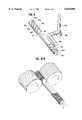
- FIG. 1is a perspective view of a dental instrument with a molded handle in accordance with the present invention
- FIG. 2is a perspective view of a single and a dental instrument with an enlarged, molded, handle illustrating a different style of knurling
- FIG. 3is a fragmentary perspective view, enlarged, of a portion of an end of a dental instrument illustrating a different form of groves;
- FIG. 4is a fragmentary, enlarged, perspective view of a portion of an end of a dental instrument illustrating a different combination of groves and knurlings;
- FIG. 5is a fragmentary, enlarged, perspective view of a portion of an end of a dental instrument illustrating and yet a different combination of groves and knurlings;
- FIG. 6illustrates a method of manufacturing a dental instrument, such as a dental instrument of FIG. 1;
- FIG. 7illustrates, schematically, an alternate method of manufacturing a dental instrument
- FIG. 8illustrates yet another method of manufacturing a dental instrument
- FIG. 9is a perspective view of a molded handle subsequent to being removed from a mold.
- FIG. 10Ais a perspective schematic view of knurling being applied to the molded handle of FIG. 9;
- FIG. 10Bis a view of another method of applying knurling to the molded handle of FIG. 9.
- FIG. 11is a perspective view of the handle of FIG. 10 with cones being affixed thereto.
- the dental instrument 10is a double ended instrument.
- the instrument 12is a single ended instrument. It will be understood that the particular tip that is used is not a limitation of the present invention.
- the instrument 10includes a large, elongated, generally cylindrical injection molded handle 20.
- the handle 20has first and second ends 20a, 20b. Each of the ends 20a, 20b exhibits a plurality of ridges, such as the ridges 22a through 22d which are carried on the end of 20a.
- the ridges 22a. . . 22dare separated from one another by serpentine peripheral groves or depressions 24a, 24b and 24c.
- the ridges 22a-22dare molded along with the handle 20 as are the groves or depressions 22a, 24c.
- Each of the ridges 22a. . . 22dextends circumferentially about the handle 20.
- Each of the ridges 22a. . . 22dis processed after the handle 20 is extracted from the mold in a knurling operation.
- each of the ridges 22a. . . 22dcarries a plurality of knurls which in the case of the dental instrument 10 are generally diamond shaped.
- different styles of knurlingcan be used without departing from the spirit and scope of the present invention.
- the handle 20can be molded for example, of a polyetherimide (available under the ULTEM brand name). Alternately, a polyethersulphone can be used. Other medical grade plastics can be used provided they exhibit similar properties such as heat and stain resistance.
- the handle 20has a diameter on the order of 3/8 of an inch or larger.
- the diamond shaped knurls of FIGS. 1can be applied in various sizes.
- a tip or probe receiving coneCarried adjacent to each of the ends, 20a, 20b is a tip or probe receiving cone, 26a, 26b.
- the cones 26a, 26bcan be formed, for example of stainless steel.
- Each of the conescarries a preformed channel (illustrated in phantom in FIG. 6) into which a respective tip or probe 28a, 28b can be inserted with a press-fit.
- a preformed channelillustrated in phantom in FIG. 6
- adhesivescould also be used.
- the tips 28a, 28b and respective channelscan be threaded for rotatable engagement.
- the cones 26a, 26bcan be inserted into the ends 20a, 20b of the handle 20, subsequent to extracting the handle 20 from the mold, and ultrasonically welded thereto. Alternately, the cones 26a, 26b can be located in the mold, as inserts prior to the injection step. When plastic is injected into the mold, that plastic fills in the voids and recesses at the base of the cones 26a, 26b and thereby locks the cones to the respective ends of the handle 20a, 20b.
- Each of the cones 26a, 26bcarries a knurled region 26a', 26b'.
- the added knurling in the cones 26a, 26benhances non-slip gripping of the instrument 10 by a dental practitioner.
- the handle 20in addition to providing enhanced gripability and enhanced resistance to slippage also reduces practitioner fatigue due to the diameter. In addition, the size and texture of the handle 20 permits a practitioner to hold and control the instrument with less force than might otherwise be required.
- the single ended instrument 12 of FIG. 2includes a large, elongated, generally cylindrical injection molded handle 40.
- the handle 40has first and second ends 40a, 40b.
- the ends 40a, 40beach carry a plurality of circumferential, spaced apart ridges 42a. . . 42d.
- the ridges 42a. . . 42dare spaced apart by molded groves or slots 44a, 44b and 44c. As was the case with the groves or slots 24a. . . 24c, the groves 44a. . . 44c extend circumferentially around the handle 40.
- Knurlsare formed on the ridges 42a. . . 42d subsequent to the molding step as discussed above with respect to the instrument 10.
- the instrument 12may carry a plurality of straight line knurls unlike the diamond shaped knurls of the instrument 10 of FIG. 1.
- the knurlscould be formed in only one end of a single ended instrument.
- the instrument 12carries a stainless steel cone 46a adjacent to the end 40a. It carries a molded end cap 46b adjacent the end 40b.
- the stainless steel coneas described above with respect to the cone 26a, can be ultrasonically welded or integrally molded to the handle 40.
- a tip or mirror 28a'can be press-fit or threaded into a corresponding channel in the stainless steel cone 46a.
- the stainless steel cone 46aalso carries knurling 46' to improve its non-slip characteristics.
- FIGS. 3 through 5illustrate alternate embodiments of the instruments 10, 12.
- the instruments 10' and 10" of FIGS. 3, 4,carry molded groves 34a-34c and 36a-36c in the form of a helix.
- the instrument 10 '" of FIG. 5carries a double helix 38a, 38b.
- various kinds of knurlingcan be used since the knurls are the result of a post-molding operation.
- FIG. 6illustrates various aspects of the process of making an instrument, such as the instrument 10.
- FIG. 6illustrates a mold M wherein the cones, such as the cones 26a', 26b' are positioned in the mold as inserts, prior to injecting plastic therein.
- the coneseach carry locking stems, such as the stems 27a and 27b. These stems extend toward one another when the cones 26a' and 27b' are inserted into the mold M.
- the fluid handle materialfills in the regions around the stems 27a and 27b and solidifies. This permanently attaches the cones 26a' and 26b' to the handle 20'.
- the tipssuch as tips 28a', 28b ' can be inserted into the cones 26a, 26b, either before or after the molding step without departing from the spirit and scope of the present invention.
- Each of the tips or probescarries a cylindrical stud, such as studs 29a, 29b which are inserted with a press-fit into respective channels 27c and 27d (illustrated in phantom in FIG. 6).
- the studs 29a, 29bcan be threaded and the channels 27c, 27d can carry mating threads to rotatably couple the tips or points to the handle 20'.
- FIG. 7illustrates an alternate method of making an instrument, such as the instrument 10.
- a previously molded handle 20"receives cones 26a' and 26b'.
- the stems, such as stems 27a and 27bare press-fit into channels molded into the ends of the handle 20".
- ultrasonic energyis applied to the handle 20" (illustrated schematically by fixtures U1 and U2).
- the applied ultrasonic energyheats, softens and permits the plastic in the handle 20", which is subject to the applied ultrasonic energy, to flow around and enclose the stems 27a, 27b thereby permanently attaching the cones 26a' and 26b' thereto.
- the handle 20is injection molded, a representation of corporate name, logo or other symbols 21 can be molded in at the same time that the handle is molded. This eliminates a secondary step.
- FIG. 8illustrates yet another method of making an instrument, such as the instrument 10.
- an elongated insert 50is positioned in a mold M'.
- the insert 50includes first and second spaced apart conical end members 52a, 52b.
- the conical end members 52a, 52bare joined by a rigid rod or stem 52c.
- the insert stem 52cis surrounded by and embedded in the plastic material. That material also fills any voids or spaces at the bases of the cones 52a, 52b thereby forming the molded handle 20'".
- the handle 20'"has integrally attached tip or probe mounting cones 52a, 52b.
- the inserted rod method of moldingreduces the amount of plastic that is required. It also has the potential to increase the flexural strength of the handle.
- FIGS. 9 through 11illustrate other aspects of manufacturing instruments, such as the instruments 10, 12.
- FIG. 9illustrates a molded part 60, which after further processing forms a handle.
- the part 60upon being ejected from the mold, such as the mold M, has an elongated cylindrical body portion 62 with first and second ends 64a, 64b.
- An axially directed channelsuch as the channel 64c, has been molded into each of the ends 64a, 64b. Further, each of the ends carries molded elevated regions, such as the regions 66a. . . 66d. The regions 66a. . . 66d are separated by molded groves 68a, 68b and 68c.
- an asymmetrically located gate 70aprovides an injection port through which the plastic material is injected into the voids of the mold M and to which the runner 70b is attached.
- attached to the runner 70bare a sprue 70c and a cold plug well 70d. The runner 70b and attached surplus plastic is removed from the body 62 subsequent to the part 60 being extracted from the mold M.
- FIG. 10Aillustrates, schematically, a process of knurling the body 62. Since the knurls are formed on the body 62 subsequent to the molding step, the same molded part can be customized for a variety of different practitioners simply by changing the fixtures used in the knurling step.
- FIG. 10Billustrates another process of knurling the body 62.
- FIG. 11illustrates a step of ultrasonic welding the stainless steel cones, such as the cones 26aand 26b to the molded part 62 to complete the manufacturing process. As illustrated in FIG. 11, the tips or points 28a, 28b can subsequently be installed in the cones 26a26b.
Landscapes
- Health & Medical Sciences (AREA)
- Oral & Maxillofacial Surgery (AREA)
- Dentistry (AREA)
- Epidemiology (AREA)
- Life Sciences & Earth Sciences (AREA)
- Animal Behavior & Ethology (AREA)
- General Health & Medical Sciences (AREA)
- Public Health (AREA)
- Veterinary Medicine (AREA)
- Injection Moulding Of Plastics Or The Like (AREA)
Abstract
Description
Claims (51)
Priority Applications (1)
| Application Number | Priority Date | Filing Date | Title |
|---|---|---|---|
| US08/688,865US5816806A (en) | 1996-07-31 | 1996-07-31 | Dental instruments with large molded handles |
Applications Claiming Priority (1)
| Application Number | Priority Date | Filing Date | Title |
|---|---|---|---|
| US08/688,865US5816806A (en) | 1996-07-31 | 1996-07-31 | Dental instruments with large molded handles |
Publications (1)
| Publication Number | Publication Date |
|---|---|
| US5816806Atrue US5816806A (en) | 1998-10-06 |
Family
ID=24766096
Family Applications (1)
| Application Number | Title | Priority Date | Filing Date |
|---|---|---|---|
| US08/688,865Expired - LifetimeUS5816806A (en) | 1996-07-31 | 1996-07-31 | Dental instruments with large molded handles |
Country Status (1)
| Country | Link |
|---|---|
| US (1) | US5816806A (en) |
Cited By (58)
| Publication number | Priority date | Publication date | Assignee | Title |
|---|---|---|---|---|
| USD425202S (en)* | 1999-01-21 | 2000-05-16 | Hu-Friedy Mfg. Co., Inc. | Dental instrument handle |
| US6109918A (en)* | 1999-01-21 | 2000-08-29 | Hu-Friedy Mfg. Co., Inc. | Dental instrument having overlapping helical scoring pattern |
| USD430298S (en)* | 1999-08-10 | 2000-08-29 | Holms Allan G | Dental instrument |
| USD435106S (en)* | 2000-01-13 | 2000-12-12 | Brian Tang | Dental applicator |
| USD435293S (en)* | 2000-01-13 | 2000-12-19 | Brian Tang | Dental tool |
| US6193515B1 (en)* | 1999-11-30 | 2001-02-27 | Hu-Friendly Mfg. Co., Inc. | Coded dental handle |
| USD444567S1 (en) | 2000-01-13 | 2001-07-03 | Brian Tang | Dental dispensing tray |
| USD446858S1 (en) | 1998-03-26 | 2001-08-21 | Allan G. Holms | Dental instrument |
| US6322362B1 (en) | 1998-03-26 | 2001-11-27 | Allan G. Holms | Dental instrument |
| US6361317B1 (en) | 2000-06-23 | 2002-03-26 | Hu-Friedy Mfg. Co., Inc. | Molded, reinforced handle |
| EP1281371A3 (en)* | 2001-07-30 | 2003-05-14 | Hu-Friedy Mfg. Co., Inc. | Dental instrument |
| US20050095558A1 (en)* | 2003-11-04 | 2005-05-05 | Jones Michael L. | Interproximal composite carver |
| US20060029906A1 (en)* | 2004-08-06 | 2006-02-09 | Hill Elizabeth J | Ergonomic dental instruments for small hands |
| US20060063130A1 (en)* | 2004-09-21 | 2006-03-23 | Discus Dental Impressions, Inc. | Dental instruments with stress relief |
| US20060070499A1 (en)* | 2004-10-04 | 2006-04-06 | Brooks Martin S | Power handle and method of using same |
| US20060084032A1 (en)* | 2004-10-14 | 2006-04-20 | Tipton David W | Rotatable dental handle |
| US20060257820A1 (en)* | 2005-05-13 | 2006-11-16 | Davis Jeffrey A | Handle for dental/medical instrument |
| US20060263737A1 (en)* | 2005-05-20 | 2006-11-23 | Ormco Corporation | Orthodontic brackets and appliances and methods of making and using orthodontic brackets |
| US20070003903A1 (en)* | 2005-06-30 | 2007-01-04 | Meuchel Dennis A | Color coded instruments |
| USD540946S1 (en)* | 2005-04-26 | 2007-04-17 | Idmos Plc | Dental apparatus |
| US20070087309A1 (en)* | 2005-10-18 | 2007-04-19 | Campion James M | Identification ring having an associated retaining clip, cover and stand |
| US20080044788A1 (en)* | 2006-08-18 | 2008-02-21 | Jansheski John M | Double ended lighted dental cleaner |
| US20080057470A1 (en)* | 2002-12-12 | 2008-03-06 | Discus Dental, Llc | Dental tool having a hand grip |
| US20080114723A1 (en)* | 1997-07-15 | 2008-05-15 | At&T Corp. | Interaction modalities for multimedia delivery and presentation |
| USD571046S1 (en)* | 2006-01-13 | 2008-06-10 | Ponzini S.P.A. | Dental implement |
| US20110223559A1 (en)* | 2010-03-12 | 2011-09-15 | Hu-Friedy Mfg. Co., Inc. | Dental handpiece system with replaceable treatment tips |
| USD660966S1 (en)* | 2011-09-09 | 2012-05-29 | Sheild Peter J | Dental instrument sleeve |
| US20120246946A1 (en)* | 2011-03-31 | 2012-10-04 | Thomas Kreitz | Knife With a Metal End Cap and Method for Fixing the End Cap |
| USD687553S1 (en)* | 2012-10-24 | 2013-08-06 | Mark Neil Coreil | Orthodontic instrument |
| US20130288196A1 (en)* | 2009-03-17 | 2013-10-31 | Manuel Barry Gordon | Ergonomic dental tools |
| US20140113246A1 (en)* | 2011-11-17 | 2014-04-24 | Loma Linda University | Method and devices for placing root repair materials for root-end cavities |
| WO2014139176A1 (en)* | 2013-03-15 | 2014-09-18 | Hu-Friedy Mfg. Co., Llc | Dental or surgical instrument and handle and method for manufacturing |
| USD729935S1 (en)* | 2013-03-15 | 2015-05-19 | Hu-Friedy Mfg. Co., Llc | Handle for a dental instrument |
| US9198738B2 (en) | 2009-03-17 | 2015-12-01 | Manuel Barry Gordon | Combination tongue and flap retractor |
| USD764665S1 (en)* | 2015-03-11 | 2016-08-23 | Lm-Instruments Oy | Handle of a dental hand instrument |
| AU2017200161A1 (en)* | 2016-02-26 | 2017-09-14 | B&L Biotech, Inc. | Dental treatment instrument |
| USD799047S1 (en)* | 2016-02-25 | 2017-10-03 | Debra A. Beckman | Oral probe |
| USD813005S1 (en)* | 2017-02-16 | 2018-03-20 | Royal Brush Manufacturing, Inc. | Handle |
| USD815508S1 (en)* | 2017-02-16 | 2018-04-17 | Royal Brush Manufacturing, Inc. | Handle |
| USD839426S1 (en)* | 2018-01-23 | 2019-01-29 | Younas Bajwa | Dental handle instrument |
| USD848156S1 (en) | 2018-02-05 | 2019-05-14 | Royal Brush Manufacturing, Inc. | Make-up brush |
| USD861355S1 (en) | 2018-02-05 | 2019-10-01 | Royal Brush Manufacturing, Inc. | Make-up brush body |
| USD870463S1 (en) | 2018-02-05 | 2019-12-24 | Royal Brush Manufacturing, Inc. | Make-up brush body |
| USD876101S1 (en) | 2018-02-05 | 2020-02-25 | Royal Brush Manufacturing, Inc. | Make-up brush |
| US10588642B2 (en)* | 2014-05-15 | 2020-03-17 | Gauthier Biomedical, Inc. | Molding process and products formed thereby |
| USD882088S1 (en)* | 2019-01-22 | 2020-04-21 | Brian Tang | Dental instrument |
| USD883483S1 (en)* | 2019-01-24 | 2020-05-05 | University Of Florida Research Foundation, Inc. | Dental instrument |
| USD884894S1 (en)* | 2019-01-24 | 2020-05-19 | University Of Florida Research Foundation, Inc. | Dental instrument |
| USD888243S1 (en)* | 2019-03-29 | 2020-06-23 | Novadent USA, Inc. | Dental handle instrument |
| USD888242S1 (en)* | 2019-03-29 | 2020-06-23 | Novadent USA, Inc. | Dental handle instrument |
| USD888241S1 (en)* | 2019-03-29 | 2020-06-23 | Novadent USA, Inc. | Dental handle instrument |
| USD893722S1 (en)* | 2018-10-19 | 2020-08-18 | Gipfel Inc. | Handle for a dental tool |
| USD918390S1 (en)* | 2019-06-13 | 2021-05-04 | Prodont Holliger | Handle for hand-held dental instruments |
| USD922577S1 (en)* | 2018-08-13 | 2021-06-15 | Evelyn Anne-Bauschka Ayers | Cavity liner placement tool |
| USD960370S1 (en) | 2020-06-29 | 2022-08-09 | Hu-Friedy Mfg. Co., Llc | Handle and grip for a dental instrument |
| USD1034998S1 (en)* | 2022-12-12 | 2024-07-09 | Surgimac Llc | Tool handle |
| USD1042836S1 (en)* | 2023-05-02 | 2024-09-17 | Haseeb Sajid | Dental instrument |
| US20240366336A1 (en)* | 2023-05-01 | 2024-11-07 | Haseeb Sajid | Dental instrument |
Citations (5)
| Publication number | Priority date | Publication date | Assignee | Title |
|---|---|---|---|---|
| US2818647A (en)* | 1954-11-22 | 1958-01-07 | Berliner Abraham | Dental instrument |
| US4060897A (en)* | 1976-04-23 | 1977-12-06 | Jean Greenstein | Device for forming dental restorations |
| USD249062S (en) | 1977-09-15 | 1978-08-22 | Norabel Ab | Dental instrument |
| US4759713A (en)* | 1985-07-25 | 1988-07-26 | Baxter Travenol Laboratories, Inc. | Disposable dental tool |
| US4795344A (en)* | 1987-01-15 | 1989-01-03 | Brewer Jr Charles A | Plaque and calculus remover for tissue integrated dental prosthesis |
- 1996
- 1996-07-31USUS08/688,865patent/US5816806A/ennot_activeExpired - Lifetime
Patent Citations (5)
| Publication number | Priority date | Publication date | Assignee | Title |
|---|---|---|---|---|
| US2818647A (en)* | 1954-11-22 | 1958-01-07 | Berliner Abraham | Dental instrument |
| US4060897A (en)* | 1976-04-23 | 1977-12-06 | Jean Greenstein | Device for forming dental restorations |
| USD249062S (en) | 1977-09-15 | 1978-08-22 | Norabel Ab | Dental instrument |
| US4759713A (en)* | 1985-07-25 | 1988-07-26 | Baxter Travenol Laboratories, Inc. | Disposable dental tool |
| US4795344A (en)* | 1987-01-15 | 1989-01-03 | Brewer Jr Charles A | Plaque and calculus remover for tissue integrated dental prosthesis |
Non-Patent Citations (3)
| Title |
|---|
| American Eagle Dental Instrument Catalog, published before filing date of patent application (Jul. 31, 1996).* |
| Hu Friedy Colours Dental Instrument Catalog in Dutch, published before filing date of patent application (Jul. 31, 1996).* |
| Hu-Friedy Colours Dental Instrument Catalog in Dutch, published before filing date of patent application (Jul. 31, 1996). |
Cited By (75)
| Publication number | Priority date | Publication date | Assignee | Title |
|---|---|---|---|---|
| US20080114723A1 (en)* | 1997-07-15 | 2008-05-15 | At&T Corp. | Interaction modalities for multimedia delivery and presentation |
| US6322362B1 (en) | 1998-03-26 | 2001-11-27 | Allan G. Holms | Dental instrument |
| USD463026S1 (en) | 1998-03-26 | 2002-09-17 | Allan G. Holms | Dental instrument |
| USD446858S1 (en) | 1998-03-26 | 2001-08-21 | Allan G. Holms | Dental instrument |
| US6109918A (en)* | 1999-01-21 | 2000-08-29 | Hu-Friedy Mfg. Co., Inc. | Dental instrument having overlapping helical scoring pattern |
| USD425202S (en)* | 1999-01-21 | 2000-05-16 | Hu-Friedy Mfg. Co., Inc. | Dental instrument handle |
| USD430298S (en)* | 1999-08-10 | 2000-08-29 | Holms Allan G | Dental instrument |
| US6193515B1 (en)* | 1999-11-30 | 2001-02-27 | Hu-Friendly Mfg. Co., Inc. | Coded dental handle |
| USD435293S (en)* | 2000-01-13 | 2000-12-19 | Brian Tang | Dental tool |
| USD444567S1 (en) | 2000-01-13 | 2001-07-03 | Brian Tang | Dental dispensing tray |
| USD435106S (en)* | 2000-01-13 | 2000-12-12 | Brian Tang | Dental applicator |
| US6361317B1 (en) | 2000-06-23 | 2002-03-26 | Hu-Friedy Mfg. Co., Inc. | Molded, reinforced handle |
| EP1281371A3 (en)* | 2001-07-30 | 2003-05-14 | Hu-Friedy Mfg. Co., Inc. | Dental instrument |
| US6729877B2 (en) | 2001-07-30 | 2004-05-04 | Hu-Friedy Mfg. Co., Inc. | Dental instrument having enlarged handle and glued cone |
| US20080057470A1 (en)* | 2002-12-12 | 2008-03-06 | Discus Dental, Llc | Dental tool having a hand grip |
| US20050095558A1 (en)* | 2003-11-04 | 2005-05-05 | Jones Michael L. | Interproximal composite carver |
| US20060029906A1 (en)* | 2004-08-06 | 2006-02-09 | Hill Elizabeth J | Ergonomic dental instruments for small hands |
| US7249948B2 (en) | 2004-08-06 | 2007-07-31 | Chapin Hill Instrument Company, Llc | Ergonomic dental instruments for small hands |
| US20080057469A1 (en)* | 2004-09-21 | 2008-03-06 | Discus Dental, Llc | Dental Instrument |
| US20060063130A1 (en)* | 2004-09-21 | 2006-03-23 | Discus Dental Impressions, Inc. | Dental instruments with stress relief |
| US20070190485A1 (en)* | 2004-09-21 | 2007-08-16 | Discus Dental Impressions, Inc. | Dental instrument |
| US20060070499A1 (en)* | 2004-10-04 | 2006-04-06 | Brooks Martin S | Power handle and method of using same |
| US20060084032A1 (en)* | 2004-10-14 | 2006-04-20 | Tipton David W | Rotatable dental handle |
| USD540946S1 (en)* | 2005-04-26 | 2007-04-17 | Idmos Plc | Dental apparatus |
| US20060257820A1 (en)* | 2005-05-13 | 2006-11-16 | Davis Jeffrey A | Handle for dental/medical instrument |
| US20090291404A1 (en)* | 2005-05-20 | 2009-11-26 | Ormco Corporation | Orthodontic brackets and appliances and methods of making and using orthodontic brackets |
| US20060263737A1 (en)* | 2005-05-20 | 2006-11-23 | Ormco Corporation | Orthodontic brackets and appliances and methods of making and using orthodontic brackets |
| US20080124674A1 (en)* | 2005-06-30 | 2008-05-29 | Meuchel Dennis A | Color coded instruments |
| US20070003903A1 (en)* | 2005-06-30 | 2007-01-04 | Meuchel Dennis A | Color coded instruments |
| US20070087309A1 (en)* | 2005-10-18 | 2007-04-19 | Campion James M | Identification ring having an associated retaining clip, cover and stand |
| USD571046S1 (en)* | 2006-01-13 | 2008-06-10 | Ponzini S.P.A. | Dental implement |
| US20080044788A1 (en)* | 2006-08-18 | 2008-02-21 | Jansheski John M | Double ended lighted dental cleaner |
| US20130288196A1 (en)* | 2009-03-17 | 2013-10-31 | Manuel Barry Gordon | Ergonomic dental tools |
| US10813718B2 (en)* | 2009-03-17 | 2020-10-27 | Manuel Barry Gordon | Ergonomic dental tools |
| US9198738B2 (en) | 2009-03-17 | 2015-12-01 | Manuel Barry Gordon | Combination tongue and flap retractor |
| US20110223559A1 (en)* | 2010-03-12 | 2011-09-15 | Hu-Friedy Mfg. Co., Inc. | Dental handpiece system with replaceable treatment tips |
| US8167616B2 (en) | 2010-03-12 | 2012-05-01 | Hu-Friedy Mfg. Co., Llc | Dental handpiece system with replaceable treatment tips |
| US20120246946A1 (en)* | 2011-03-31 | 2012-10-04 | Thomas Kreitz | Knife With a Metal End Cap and Method for Fixing the End Cap |
| USD660966S1 (en)* | 2011-09-09 | 2012-05-29 | Sheild Peter J | Dental instrument sleeve |
| US20140113246A1 (en)* | 2011-11-17 | 2014-04-24 | Loma Linda University | Method and devices for placing root repair materials for root-end cavities |
| USD687553S1 (en)* | 2012-10-24 | 2013-08-06 | Mark Neil Coreil | Orthodontic instrument |
| USD805641S1 (en) | 2013-03-15 | 2017-12-19 | Hu-Friedy Mfg. Co., Llc | Handle for a dental instrument |
| USD754345S1 (en) | 2013-03-15 | 2016-04-19 | Hu-Friedy Mfg. Co., Llc | Handle for a dental instrument |
| WO2014139176A1 (en)* | 2013-03-15 | 2014-09-18 | Hu-Friedy Mfg. Co., Llc | Dental or surgical instrument and handle and method for manufacturing |
| USD790061S1 (en) | 2013-03-15 | 2017-06-20 | Hu-Friedy Mfg. Co., Llc | Handle for a dental instrument |
| USD729935S1 (en)* | 2013-03-15 | 2015-05-19 | Hu-Friedy Mfg. Co., Llc | Handle for a dental instrument |
| US10588642B2 (en)* | 2014-05-15 | 2020-03-17 | Gauthier Biomedical, Inc. | Molding process and products formed thereby |
| US12369928B2 (en) | 2014-05-15 | 2025-07-29 | Gauthier Biomedical, Inc | Method of forming a reusable surgical implement |
| USD764665S1 (en)* | 2015-03-11 | 2016-08-23 | Lm-Instruments Oy | Handle of a dental hand instrument |
| USD799047S1 (en)* | 2016-02-25 | 2017-10-03 | Debra A. Beckman | Oral probe |
| AU2017200161A1 (en)* | 2016-02-26 | 2017-09-14 | B&L Biotech, Inc. | Dental treatment instrument |
| AU2017200161B2 (en)* | 2016-02-26 | 2018-08-30 | B&L Biotech, Inc. | Dental treatment instrument |
| US10646305B2 (en) | 2016-02-26 | 2020-05-12 | B&L Biotech, Inc. | Dental treatment instrument |
| USD813005S1 (en)* | 2017-02-16 | 2018-03-20 | Royal Brush Manufacturing, Inc. | Handle |
| USD815508S1 (en)* | 2017-02-16 | 2018-04-17 | Royal Brush Manufacturing, Inc. | Handle |
| USD839426S1 (en)* | 2018-01-23 | 2019-01-29 | Younas Bajwa | Dental handle instrument |
| USD870463S1 (en) | 2018-02-05 | 2019-12-24 | Royal Brush Manufacturing, Inc. | Make-up brush body |
| USD876101S1 (en) | 2018-02-05 | 2020-02-25 | Royal Brush Manufacturing, Inc. | Make-up brush |
| USD861355S1 (en) | 2018-02-05 | 2019-10-01 | Royal Brush Manufacturing, Inc. | Make-up brush body |
| USD848156S1 (en) | 2018-02-05 | 2019-05-14 | Royal Brush Manufacturing, Inc. | Make-up brush |
| USD922577S1 (en)* | 2018-08-13 | 2021-06-15 | Evelyn Anne-Bauschka Ayers | Cavity liner placement tool |
| USD893722S1 (en)* | 2018-10-19 | 2020-08-18 | Gipfel Inc. | Handle for a dental tool |
| USD882088S1 (en)* | 2019-01-22 | 2020-04-21 | Brian Tang | Dental instrument |
| USD883483S1 (en)* | 2019-01-24 | 2020-05-05 | University Of Florida Research Foundation, Inc. | Dental instrument |
| USD884894S1 (en)* | 2019-01-24 | 2020-05-19 | University Of Florida Research Foundation, Inc. | Dental instrument |
| USD888241S1 (en)* | 2019-03-29 | 2020-06-23 | Novadent USA, Inc. | Dental handle instrument |
| USD888242S1 (en)* | 2019-03-29 | 2020-06-23 | Novadent USA, Inc. | Dental handle instrument |
| USD888243S1 (en)* | 2019-03-29 | 2020-06-23 | Novadent USA, Inc. | Dental handle instrument |
| USD918390S1 (en)* | 2019-06-13 | 2021-05-04 | Prodont Holliger | Handle for hand-held dental instruments |
| USD960370S1 (en) | 2020-06-29 | 2022-08-09 | Hu-Friedy Mfg. Co., Llc | Handle and grip for a dental instrument |
| USD1016287S1 (en) | 2020-06-29 | 2024-02-27 | Hu-Friedy Mfg. Co., Llc | Handle and grip for a dental instrument |
| USD1097155S1 (en) | 2020-06-29 | 2025-10-07 | Hu-Friedy Mfg. Co., Llc | Handle for dental instrument |
| USD1034998S1 (en)* | 2022-12-12 | 2024-07-09 | Surgimac Llc | Tool handle |
| US20240366336A1 (en)* | 2023-05-01 | 2024-11-07 | Haseeb Sajid | Dental instrument |
| USD1042836S1 (en)* | 2023-05-02 | 2024-09-17 | Haseeb Sajid | Dental instrument |
Similar Documents
| Publication | Publication Date | Title |
|---|---|---|
| US5816806A (en) | Dental instruments with large molded handles | |
| US6257887B1 (en) | Dental hand instrument | |
| JP7394166B2 (en) | interdental cleaner | |
| US6223440B1 (en) | Autoclavable stainless steel medical instruments with polypropylene injected color handles | |
| US20060084032A1 (en) | Rotatable dental handle | |
| US6361317B1 (en) | Molded, reinforced handle | |
| US5167647A (en) | Catheter with a strain relief member | |
| US6322362B1 (en) | Dental instrument | |
| US6186792B1 (en) | Method of coating with a disposable dental applicator | |
| JP5529583B2 (en) | Dental root canal treatment instrument and manufacturing method thereof | |
| US5488751A (en) | Interdental toothbrush | |
| EP1101573B1 (en) | Handle for a hand tool and method for producing same | |
| AU2001287294B2 (en) | Method of forming tool with dual-material handle | |
| US9849579B2 (en) | Method of forming a modular handle for a tool | |
| EP0908288B1 (en) | Multi-colored paintbrush handle and process and apparatus for manufacturing said handle | |
| WO2010122681A1 (en) | Tool for applying cosmetics | |
| US20020120283A1 (en) | Curette with detachable tip | |
| US20080124674A1 (en) | Color coded instruments | |
| US7226289B2 (en) | Method for overmolding polymers over dental tools | |
| EP3122209A1 (en) | Brush head arrangements | |
| WO2000056185A1 (en) | Dental hygiene device with easily mounted and identified dental hygiene element | |
| US6193515B1 (en) | Coded dental handle | |
| US6328566B1 (en) | ID system for ultrasonic dental inserts | |
| JPH10155546A (en) | Inter-tooth brush | |
| JP2000033010A (en) | toothbrush |
Legal Events
| Date | Code | Title | Description |
|---|---|---|---|
| AS | Assignment | Owner name:HU-FRIEDY MFG. CO., INC., ILLINOIS Free format text:ASSIGNMENT OF ASSIGNORS INTEREST;ASSIGNORS:HERBST, WALTER B.;DEMAR, DAVID A.;HESS, WILLIAM E.;REEL/FRAME:008481/0835 Effective date:19960720 | |
| STCF | Information on status: patent grant | Free format text:PATENTED CASE | |
| FEPP | Fee payment procedure | Free format text:PAT HOLDER CLAIMS SMALL ENTITY STATUS, ENTITY STATUS SET TO SMALL (ORIGINAL EVENT CODE: LTOS); ENTITY STATUS OF PATENT OWNER: LARGE ENTITY | |
| FPAY | Fee payment | Year of fee payment:4 | |
| REMI | Maintenance fee reminder mailed | ||
| FPAY | Fee payment | Year of fee payment:8 | |
| FEPP | Fee payment procedure | Free format text:PAT HOLDER NO LONGER CLAIMS SMALL ENTITY STATUS, ENTITY STATUS SET TO UNDISCOUNTED (ORIGINAL EVENT CODE: STOL); ENTITY STATUS OF PATENT OWNER: LARGE ENTITY | |
| REFU | Refund | Free format text:REFUND - PAYMENT OF MAINTENANCE FEE, 12TH YR, SMALL ENTITY (ORIGINAL EVENT CODE: R2553); ENTITY STATUS OF PATENT OWNER: LARGE ENTITY | |
| FPAY | Fee payment | Year of fee payment:12 | |
| AS | Assignment | Owner name:HU-FRIEDY MFG. CO., LLC, ILLINOIS Free format text:MERGER;ASSIGNOR:HU-FRIEDY MFG. CO., INC.;REEL/FRAME:024640/0368 Effective date:20100331 |