US5816749A - Modular block retaining wall system - Google Patents
Modular block retaining wall systemDownload PDFInfo
- Publication number
- US5816749A US5816749AUS08/716,626US71662696AUS5816749AUS 5816749 AUS5816749 AUS 5816749AUS 71662696 AUS71662696 AUS 71662696AUS 5816749 AUS5816749 AUS 5816749A
- Authority
- US
- United States
- Prior art keywords
- wall
- blocks
- courses
- retaining wall
- wall blocks
- Prior art date
- Legal status (The legal status is an assumption and is not a legal conclusion. Google has not performed a legal analysis and makes no representation as to the accuracy of the status listed.)
- Expired - Lifetime
Links
Images


Classifications
- E—FIXED CONSTRUCTIONS
- E04—BUILDING
- E04C—STRUCTURAL ELEMENTS; BUILDING MATERIALS
- E04C1/00—Building elements of block or other shape for the construction of parts of buildings
- E04C1/39—Building elements of block or other shape for the construction of parts of buildings characterised by special adaptations, e.g. serving for locating conduits, for forming soffits, cornices, or shelves, for fixing wall-plates or door-frames, for claustra
- E04C1/395—Building elements of block or other shape for the construction of parts of buildings characterised by special adaptations, e.g. serving for locating conduits, for forming soffits, cornices, or shelves, for fixing wall-plates or door-frames, for claustra for claustra, fences, planting walls, e.g. sound-absorbing
- E—FIXED CONSTRUCTIONS
- E02—HYDRAULIC ENGINEERING; FOUNDATIONS; SOIL SHIFTING
- E02D—FOUNDATIONS; EXCAVATIONS; EMBANKMENTS; UNDERGROUND OR UNDERWATER STRUCTURES
- E02D29/00—Independent underground or underwater structures; Retaining walls
- E02D29/02—Retaining or protecting walls
- E02D29/0225—Retaining or protecting walls comprising retention means in the backfill
- E02D29/0241—Retaining or protecting walls comprising retention means in the backfill the retention means being reinforced earth elements
- E—FIXED CONSTRUCTIONS
- E02—HYDRAULIC ENGINEERING; FOUNDATIONS; SOIL SHIFTING
- E02D—FOUNDATIONS; EXCAVATIONS; EMBANKMENTS; UNDERGROUND OR UNDERWATER STRUCTURES
- E02D2200/00—Geometrical or physical properties
- E02D2200/13—Geometrical or physical properties having at least a mesh portion
- E—FIXED CONSTRUCTIONS
- E02—HYDRAULIC ENGINEERING; FOUNDATIONS; SOIL SHIFTING
- E02D—FOUNDATIONS; EXCAVATIONS; EMBANKMENTS; UNDERGROUND OR UNDERWATER STRUCTURES
- E02D2250/00—Production methods
- E02D2250/0007—Production methods using a mold
- E—FIXED CONSTRUCTIONS
- E02—HYDRAULIC ENGINEERING; FOUNDATIONS; SOIL SHIFTING
- E02D—FOUNDATIONS; EXCAVATIONS; EMBANKMENTS; UNDERGROUND OR UNDERWATER STRUCTURES
- E02D2300/00—Materials
- E02D2300/0004—Synthetics
- E—FIXED CONSTRUCTIONS
- E02—HYDRAULIC ENGINEERING; FOUNDATIONS; SOIL SHIFTING
- E02D—FOUNDATIONS; EXCAVATIONS; EMBANKMENTS; UNDERGROUND OR UNDERWATER STRUCTURES
- E02D2300/00—Materials
- E02D2300/0004—Synthetics
- E02D2300/0018—Cement used as binder
- E02D2300/002—Concrete
- E—FIXED CONSTRUCTIONS
- E04—BUILDING
- E04B—GENERAL BUILDING CONSTRUCTIONS; WALLS, e.g. PARTITIONS; ROOFS; FLOORS; CEILINGS; INSULATION OR OTHER PROTECTION OF BUILDINGS
- E04B2/00—Walls, e.g. partitions, for buildings; Wall construction with regard to insulation; Connections specially adapted to walls
- E04B2/02—Walls, e.g. partitions, for buildings; Wall construction with regard to insulation; Connections specially adapted to walls built-up from layers of building elements
- E04B2002/0202—Details of connections
- E04B2002/0204—Non-undercut connections, e.g. tongue and groove connections
- E04B2002/0206—Non-undercut connections, e.g. tongue and groove connections of rectangular shape
- E—FIXED CONSTRUCTIONS
- E04—BUILDING
- E04B—GENERAL BUILDING CONSTRUCTIONS; WALLS, e.g. PARTITIONS; ROOFS; FLOORS; CEILINGS; INSULATION OR OTHER PROTECTION OF BUILDINGS
- E04B2/00—Walls, e.g. partitions, for buildings; Wall construction with regard to insulation; Connections specially adapted to walls
- E04B2/02—Walls, e.g. partitions, for buildings; Wall construction with regard to insulation; Connections specially adapted to walls built-up from layers of building elements
- E04B2002/0202—Details of connections
- E04B2002/0243—Separate connectors or inserts, e.g. pegs, pins or keys
- E04B2002/0245—Pegs or pins
Definitions
- This inventionrelates to a modular wall block system, methods and apparatus for making the wall blocks, and retaining walls formed therefrom.
- the wall blocks of this inventionare designed for ease in positioning and locating individual blocks relative to each other in one of a vertically aligned or a vertically staggered orientation during construction of civil engineering structures.
- Relatively low retaining wallsmay be made entirely of the inventive blocks, with or without tie-backs such as reinforcing sheets of grid-like material.
- the blocks of this inventionare adapted for use with earlier modular wall blocks of a more robust nature for producing less expensive retaining walls in more critical environments or to add architectural interest to walls built with a mixture of such blocks.
- Retaining wallsare commonly used for architectural and site development applications. Use of full height pre-cast concrete wall panels for wall-facing elements in a retaining wall requires, during construction, that the panels be placed using a crane because they are very large, perhaps 8 by 12 feet or even larger and, as a result, are quite heavy such that they cannot be readily manhandled.
- retaining wallshave been formed from modular wall blocks which are typically relatively small as compared to cast wall panels. The assembly of such modular wall blocks usually does not require heavy equipment.
- Each blockcan be handled by a single person and are used to form retaining wall structures by arranging a plurality of blocks in courses superimposed on each other, much like laying of brick or the like.
- Each blockincludes a body with a front face which forms the exterior surface of the formed retaining wall.
- modular wall blockshave been formed of concrete, commonly mixed in a batching plant with only enough water to hydrate the cement and hold the unit together.
- Such blockshave been commercially made with the surfaces intended to form the top and bottom of the wall block extending generally horizontally.
- the high-speed manufacturing processwhich provides a mold box having only sides, without a top or bottom, positioned on top of a steel pallet which underlies the mold box to create a temporary bottom plate.
- a concrete distributor boxbrings concrete from the batcher and places the concrete in the mold box and includes a blade which levels the concrete across the open top of the mold box.
- a stripper/compactoris lowered into the open, upper end of the box and contacts the concrete to imprint the block with a desired pattern and compresses the concrete under high pressure.
- the steel pallet located at the bottom of the mold boxresists this pressure.
- a vibratorthen vibrates the mold box to aid in concrete consolidation. After approximately two to four seconds, the steel pallet is moved away from the bottom of the mold box which has been positioned above a conveyor belt. The stripper/compactor continues to push on the formed concrete to push the modular wall block out of the mold box onto the conveyor belt. This process takes about seven to nine seconds to manufacture a single wall block. The formed wall block is cured for approximately one day to produce the final product.
- These wall blocksinclude the use of a comb or connector which includes a multiplicity of downwardly extending fingers or teeth adapted to engage in a transversely extending, upwardly opening groove in the top surface of a lower block to selectively secure grid-like sheets of retaining material thereto, with upwardly extending elongated tabs adapted to be received in a downwardly opening groove or slot in the bottom surface of a superimposed block to position or locate the front faces of upper courses of wall blocks relative to lower courses.
- the front faces of the blocks in superimposed coursesmay be vertically aligned or vertically offset.
- a modular wall block system having these attributeswhich was also capable of integration in retaining walls built from the modular wall blocks of U.S. Pat. No. 5,540,525 and the related applications identified above, would be especially commercially desirable to minimize the costs of such constructions where possible, and to permit walls built from such blocks to incorporate the modified blocks for architectural embellishment.
- a primary object of this inventionis the provision of a modular wall block system, a method and apparatus for making such blocks, and retaining walls built therefrom, which satisfy all of the foregoing desiderata, and others.
- the modular wall blocks of this inventionare preferably smaller and lighter in weight than the previous design.
- each wall blockincludes integral positioning or locating projections extending upwardly from its top surface which cooperate with downwardly opening grooves in the bottom surface of juxtaposed blocks to selectively position the front faces of superimposed courses either vertically aligned or offset rearwardly. This avoids the need for extraneous connector devices where the nature of the retaining wall does not require same.
- the projections and groovesare preferably dimensioned to coordinate with the width of the tabs on the connector combs of the earlier modular wall blocks so as to enable the integration of the different forms of wall blocks in a common retaining wall, if desired, without losing the ability to selectively align or offset the front faces by manipulating the orientation of the comb.
- each modular wall blockis formed with a pair of integral projections extending upwardly from its top surface, transversely across the block, and spaced from each other and from the front face of the block.
- Each blockis also formed with a pair of downwardly opening grooves in its bottom surface, extending transversely across the block, and spaced from each other and from the front face.
- the upwardly extending projectionsdefine between them an upwardly opening groove, and the downwardly opening grooves define between them a downwardly extending projection.
- the width of the upwardly opening groove separating the two upwardly extending projectionsis substantially equal to the width of the downwardly extending projection separating the two downwardly opening grooves.
- the downwardly opening groove closest to the front face of the blockhas a width equal to or slightly larger than the width of the upwardly extending projection located closest to the front face.
- the width of the second or rearmost downwardly opening grooveis sufficient to encompass both of the upwardly extending projections.
- each superior blockis positioned such that its downwardly extending projection separating the downwardly opening grooves in its lower surface is engaged in the upwardly opening groove separating the upwardly extending projections in an inferior block, i.e., each of the upwardly extending projections in the lower block is received in a different downwardly opening groove in the superimposed block.
- the superior blockis positioned such that both of the upwardly extending projections on an inferior block fit within the rearward most downwardly opening groove in the lower surface.
- the height of the upwardly extending projectionsis equal to or less than the depth of the two downwardly opening grooves and all of the projections and grooves preferably extend across the entire width of each block to enable blocks to be slid laterally to adjust the lateral orientation of the blocks in superimposed courses.
- the width of the larger downwardly opening groovegenerally the same as the combined width of the pair of upwardly extending projections on each of the blocks of this invention, it is preferably generally the same as the width of the elongated tabs on the connector comb of the aforementioned earlier modular wall block systems so that courses of both types of blocks may be freely inter engaged in building retaining walls for certain applications.
- selected courses of the different blocksmay be integrated to provide a retaining wall with a decorative change in pattern, color or front face design for aesthetic or architectural contrast.
- each modular wall block of the present inventionis preferably about 35/8 inches high, or about half the height of the previous modular wall blocks, about 8 inches wide at its front face, again about half the width of the previous blocks, tapering on one side to about 6 inches wide at its rear face to permit a slight curvature to a retaining wall built therefrom, and about 12 inches deep, the same as the previous blocks.
- the weight of the blocks of this inventionmay vary depending upon the dimensions and the materials used, but these blocks are generally designed to weigh about 20 pounds, making them light enough to be stacked for constructing a retaining wall, even by a user of limited experience or strength.
- the courses of modular wall blocksneed not be reinforced by tie-back sheets.
- sheets of grid-like materialmay be interposed at selected levels to extend rearwardly from the retaining wall and thereby reinforce the mass of soil behind the wall in a well known manner.
- another object of this inventionis to provide simple and inexpensive modular wall blocks which can optionally include a recess, which may be easily formed by the mold liner and division plates, for reception and retention of edge portions of extended lengths of grid-like reinforcing sheet material between selected courses of such blocks in a retaining wall built therefrom.
- reinforcing grid sheetsmay be secured to the retaining wall by the comb connectors where necessary or desirable.
- grid-like sheet materialas used herein and the appended claims is to be understood as encompassing any continuous sheet material having one or more apertures formed therein in any conventional manner.
- preferred materialsmay be uniaxially or biaxially oriented integral structural geogrids or bonded composite open mesh structural textiles, of woven, non-woven and knitted construction. A description of preferred forms of all such materials is found in co-pending, commonly assigned U.S. patent application Ser. Nos. 08/643,182 filed May 9, 1996, and 08/696,604 filed Aug. 14, 1996, the subject matters of which are incorporated herein in their entirety by reference.
- uniaxially or biaxially oriented integral structural geogridsare commercially available from The Tensar Corporation of Atlanta, Ga. and are preferably made by the process disclosed in U.S. Pat. No. 4,374,798, the subject matter of which is also incorporated herein in its entirety by reference.
- a high strength integral geogridmay be formed by stretching an apertured plastic sheet material. Utilizing the uniaxial techniques, a multiplicity of molecularly-oriented elongated strands and transversely extending bars which are substantially unoriented or less-oriented than the strands are formed in a sheet of high density polyethylene, although other polymer materials may be used in lieu thereof. The strands and bars together define a multiplicity of grid openings. With biaxial stretching, the bars are also formed into oriented strands.
- the preferred grid-like sheetis an integral uniaxially oriented geogrid.
- integral biaxial geogrids or grid materialsthat have been made by different techniques such as woven, knitted or netted grid materials formed of various polymers including the polyolefins, polyamides, polyesters and the like or fiberglass, may be used.
- any grid-like sheet materialsincluding steel (welded wire) grids are suitable.
- bonded composite open mesh structural textiles, woven, non-woven or knitted as disclosed in the aforementioned application Ser. Nos. 08/643,182 and 08/696,604may be useful.
- FIG. 1is a schematic side elevational view of one form of a modular wall block according to the instant inventive concepts
- FIG. 2is a top plan view thereof
- FIG. 3is a schematic side elevational view showing the manner in which three courses of wall blocks may be stacked, the blocks of the lower two courses being superimposed with their front faces vertically aligned and the blocks of the upper two courses being superimposed with their front faces vertically offset for illustrative purposes;
- FIG. 4is a schematic side elevational view showing the manner in which the inventive wall blocks of the present invention may be integrated with courses of wall blocks of the type using a comb or connector therebetween, the blocks of each successive course having their front faces rearwardly offset for structural stability of the retaining wall and/or architectural design;
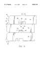
- FIG. 5is a view similar to FIG. 4 in which the front faces of selective courses of the wall blocks are vertically aligned with each other, while the front faces of other courses are vertically offset;
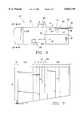
- FIG. 6is a side elevational view similar to FIG. 1 of a modular wall block according to an alternate embodiment of the instant inventive concepts wherein a recess is provided in the rear of the upper surface thereof to accommodate the end portions of a grid-like sheet of reinforcing material;
- FIG. 7is a top plan view thereof
- FIG. 8is a side elevational view similar to FIG. 3 showing the manner in which three courses of wall blocks of the type shown in FIG. 6 may be stacked with sheets of grid-like reinforcing material captured therebetween;
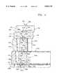
- FIG. 9is a schematic top plan view of one form of mold adapted to produce six modular wall blocks on their side according to a preferred manufacturing technique of the instant inventive concepts.
- FIGS. 1 through 3one embodiment of a modular wall block is schematically shown at 10 as comprising a front face 12, sidewalls 14, 16, a rear wall 18, an upper or top surface 20, and a lower or bottom surface 22. It is understood that the blocks 10 may be inverted in use, but the orientation shown in FIG. 1 facilitates integration with blocks utilizing a comb connector as discussed below with reference to FIGS. 4 and 5.
- the front faces of the modular wall blockscan have any aesthetic or functional design. They can be planar, convex, concave, smooth, rough or have any configuration consistent with architectural or other requirements. In the embodiments shown, the front face is of a generally planar configuration.
- each of the projections 24 and 26preferably have a width of about 0.50 inches and a height of about 0.8 inches.
- the projections 24, 26are separated by the width of the groove 28, approximately 0.625 inches.
- leading edge 36 of the projection 24is spaced approximately 5.115 inches from front face 12.
- the total distance from the front of projection 24 to the rear of projection 26, including the groove 28 located therebetween,is approximately 1.625 inches.
- grooves 38 and 40On the lower surface 22 of the block 10 are two downwardly opening grooves 38 and 40. Extending downwardly between the two grooves 38 and 40 is a projection 42.
- the width of groove 38is approximately 0.8 inches, whereas the width of groove 40 is approximately 1.625 inches, the same or slightly larger than the combined width of the two upwardly extending projections 24, 26.
- the width of projection 42is approximately 0.625 inches, the same or slightly less than upwardly opening groove 28.
- Grooves 38 and 40 and projection 42have a depth and height, respectively, of approximately 1.0 inch.
- leading edge 49 of groove 38is located approximately 3.69 inches from the front face 12, whereas the leading edge 50 of groove 40 is located the same distance from the front face 12 as the leading edge 36 of projection 24, approximately 5.115 inches.
- a typical block as shown in FIGS. 1 and 2has an overall length from front face 12 to rear face 18 of about 12 inches and a height of about 35/8 inches.
- the width of the block at front face 12is about 8 inches across, whereas the width of the block at rear face 18 is approximately 6 inches.
- Side 16is tapered at an angle of approximately 7° from front face 12 to enable a retaining wall with some curvature to be constructed with such blocks. In doing so, it may be necessary for portions of the projections 24, 26 or 42 to be knocked off selected walls to permit juxtaposed blocks to be angled slightly with respect to each other.
- the front face 12includes upper and lower angled or slanted surfaces 56 and 58 merging with the top and bottom surfaces 20, 22, respectively, of the block 10.
- the tapered side 16 and the angled surfaces 56, 58result from the preferred molding technique to be discussed in more detail hereinafter with reference to FIG. 9.
- the front faces of superimposed courses of wall blockscan be selectively arranged in a vertically aligned orientation or in a vertically offset orientation.
- block 10bis positioned on block 10a such that the projections 24a, 26a of block 10a fit within the enlarged groove 40b of block 10b. Since the separation distance between the outermost surfaces of projections 24a and 26a is the about the same as the width of the groove 40b, the two projections fit within the groove and at the same time position the front faces 12a and 12b in a vertically aligned orientation.
- the downwardly extending projection 42c in the lower surface of block 10cis placed in the upwardly opening groove 28b between the projections 24b and 26b in the upper surface of block 10b.
- the projection 24b on block 10bis then located in groove 38c, whereas the projection 26b is located in groove 40c.
- capsmay be provided (not shown) which are the same as blocks 10 in every way, except that the upper surface is generally smooth or planar to form the top of a retaining wall.
- FIG. 3The arrangement shown in FIG. 3 is for illustrative purposes since, for most applications, the front faces of all the blocks in a retaining wall will be either vertically aligned, or vertically offset. However, for architectural interest, a mixture of these arrangements is possible with the blocks of this invention.
- Wall blocks according to the present inventionmay be used in conjunction with wall blocks of the type disclosed in U.S. Pat. No. 5,540,525 or patent application Ser. Nos. 08/370,324(now U.S. Pat. No. 4,860,505), 08/591,266 (now U.S. Pat. No. 5,673,530) or 08/591,319.
- courses of wall blocks 100 of the type as seen particularly in application Ser. No. 08/370,324are integrated with courses of wall blocks 10 of the type disclosed herein.
- the wall blocks 100each include an upwardly opening groove 102 and a wider downwardly opening groove or slot 104.
- a connector device or comb 105includes a plurality of downwardly projecting serrated fingers 106 and a plurality of enlarged and offset tabs 108 extending above the fingers 106.
- the fingers 106may be inserted through apertures in the end of a sheet 110 of grid-like reinforcing material and into the groove 102 in the upper surface of a wall block 100 to secure the reinforcing sheet thereto, the upper surface of the wall blocks 100 being cut back or recessed as seen at 112 to accommodate the grid-like sheet 110.
- the combs 105a, 105bAs shown in FIG. 4, between courses 120 and 121 and 121 and 122, the combs 105a, 105b, respectively, have portions of their tabs 108a, 108b projecting rearwardly of their fingers 106a, 106b. With the combs oriented in this manner, when the tabs 108a, 108b are received in the slots 104b, 104c, respectively, of superimposed wall blocks, the front faces 125a, 125b, 125c of the blocks 100a, 100b, 100c, are vertically offset.
- tabs 108cmay be received in the enlarged downwardly opening groove 40d of a block 10d according to the instant inventive concepts, to offset the front faces 125c and 12d between the courses 122 and 123.
- a further course 124 of modular wall blocks 10e according to this inventionmay then be positioned as in the upper course of FIG. 3 to offset the front faces 12d and 12e of the wall blocks in courses 123 and 124, and additional courses of either type of wall block can be added to attain the full height of the retaining wall.
- a retaining wallis schematically illustrated having three lower courses 130, 131 and 132 of wall blocks 100a, 100b and 100c of the type disclosed in application Ser. No. 08/370,324(now U.S. Pat. No. 4,860,505), two courses, 134 and 135, of wall blocks 10d and 10e according to the instant invention, and an additional course 135 of wall blocks 100f of the previous type, for architectural interest.
- the combs 105a and 105b between courses 130 and 131, and 131 and 132, respectively,are reversed from the orientation seen in FIG. 4 thereby vertically aligning the front faces 125a, 125b and 125c in courses 130, 131 and 132.
- the comb 105cmay be oriented as in FIG. 4 to offset the blocks 10d and 10e in courses 133 and 134, if desired for architectural interest, and then one or more further courses, such as shown at 135, of the earlier style blocks schematically illustrated at 100f, may be provided, as necessary.
- wall blocks 10 of the present inventionmay form upper or intermediate courses integrated with wall blocks according to the earlier inventions in order to minimize cost or to enhance the architectural interest of a retaining wall.
- FIGS. 6-8an alternate, slightly modified embodiment 10' of the wall block of the present invention is shown wherein a recess 150 is provided in the rearward portion of the upper surface 20', extending to the rear surface 18'.
- the leading edge 152 of the recess 150is approximately 0.70 inches deep.
- a horizontally extending surface 154preferably defines the portion of the recess 150 extending rearwardly from the leading edge 152 until intersecting surface 156 which tapers upwardly at a slight inclination for approximately 2 inches until reaching rear surface 18'.
- This embodiment of wall block 10'is desirable in constructing walls of a height above approximately 4 feet.
- the recess 150accommodates the rearward edge portion of a grid-like sheet 110 of reinforcing material such as a uniaxially oriented integral geogrid comprising bars 111 and strands 113, together defining a plurality of openings in a well known manner.
- the strands 113extend rearwardly from the bars 111 and into fill material behind a wall formed by blocks of the present invention.
- the forward most bar 111 of the sheet 110rests in the portion 154 of the recess 150 and a superimposed wall block captures the sheet 110 in the recess 150.
- FIG. 8This is best shown in FIG. 8 where a plurality of blocks 10a', 10b' and 10c' form successive superimposed courses 160, 161, 162.
- the forward edge portions of the reinforcing sheet 110a'is received between the lower surface 22b' of block 10b' and the tapered opening formed by recess 150a', serving to retain bar 111a' and, thereby, the length of sheet material 110a' extending rearwardly therefrom.
- a mold 200is preferably used in forming a plurality of blocks such as 10' shown in FIG. 6, a mold 200 is preferably used.
- six blocks 10'will be formed. It is understood that block 10 as shown in FIG. 1 is formed in a similar manner, but without the formation of a recess 150 in the rear portion of the upper surface 20 thereof.
- the configuration of the liner plates 202 and 204forms outermost edge portions of the upper surfaces of two interconnected double-blocks.
- division plates 206 and 208Located between the two edge portions 202 and 204 are division plates 206 and 208.
- Division plate 206is used to shape the lower surface of two double-blocks 210, 212, whereas the division plate 208 includes the formation of an upper surface of the double-block 212 on one side and the lower surface of a further double-block 214 on the other side.
- three elongated double-blocks 210, 212 and 214are formed, each of which includes spaced projections 211, 213 and recesses 215 in one surface and spaced grooves 217, 219 in the other surface.
- triangular notches 216, 218are located on opposite sides.
- This technique of forming the wall blocks of this invention on their sideis particularly efficient in permitting the production of multiple wall blocks in the same size mold box as was used heretofore to produce only a single block because the footprint of the sides of the blocks of this invention is substantially smaller than the footprint of the top and bottom surfaces.
- the bottom of the moldcan be flat to produce the flat side of the resultant wall blocks, and the upper molding member (not shown) can include portions adapted to impress the taper into the other side of the wall blocks and to push the double-blocks from the mold when the concrete has set sufficiently, and the bottom plate has been withdrawn.
Landscapes
- Engineering & Computer Science (AREA)
- Civil Engineering (AREA)
- Structural Engineering (AREA)
- Architecture (AREA)
- Environmental & Geological Engineering (AREA)
- Life Sciences & Earth Sciences (AREA)
- General Life Sciences & Earth Sciences (AREA)
- Mining & Mineral Resources (AREA)
- Paleontology (AREA)
- General Engineering & Computer Science (AREA)
- Retaining Walls (AREA)
Abstract
Description
Claims (26)
Priority Applications (1)
| Application Number | Priority Date | Filing Date | Title |
|---|---|---|---|
| US08/716,626US5816749A (en) | 1996-09-19 | 1996-09-19 | Modular block retaining wall system |
Applications Claiming Priority (1)
| Application Number | Priority Date | Filing Date | Title |
|---|---|---|---|
| US08/716,626US5816749A (en) | 1996-09-19 | 1996-09-19 | Modular block retaining wall system |
Publications (1)
| Publication Number | Publication Date |
|---|---|
| US5816749Atrue US5816749A (en) | 1998-10-06 |
Family
ID=24878778
Family Applications (1)
| Application Number | Title | Priority Date | Filing Date |
|---|---|---|---|
| US08/716,626Expired - LifetimeUS5816749A (en) | 1996-09-19 | 1996-09-19 | Modular block retaining wall system |
Country Status (1)
| Country | Link |
|---|---|
| US (1) | US5816749A (en) |
Cited By (83)
| Publication number | Priority date | Publication date | Assignee | Title |
|---|---|---|---|---|
| US6019550A (en)* | 1996-05-21 | 2000-02-01 | Nelton Limited | Modular block retaining wall construction |
| WO2000022241A1 (en)* | 1998-10-09 | 2000-04-20 | Omnivec Enterprises Inc. | Retaining wall blocks |
| US6082933A (en)* | 1998-06-09 | 2000-07-04 | Nicolock Of Long Island | Concrete block |
| US6152655A (en)* | 1999-05-05 | 2000-11-28 | Hull; Kent D | Masonry block for retaining and freestanding walls |
| US6224295B1 (en)* | 1996-08-09 | 2001-05-01 | Derrick Ian Peter Price | Soil reinforcement |
| US6253518B1 (en) | 1998-12-24 | 2001-07-03 | Tony J. Azar | Mortarless brick |
| US6287054B1 (en) | 2000-05-18 | 2001-09-11 | Atlantech International Inc. | Plantable wall block assembly and retaining wall formed therefrom |
| US6338597B1 (en)* | 1998-03-27 | 2002-01-15 | Anchor Wall Systems, Inc. | Modular retaining wall system |
| FR2812893A1 (en)* | 2000-08-08 | 2002-02-15 | Freyssinet Int Stup | SIDING WALL OF A REINFORCED SUPPORT STRUCTURE AND REINFORCEMENT BLOCK FOR THE SAME |
| US6398458B1 (en)* | 1996-12-24 | 2002-06-04 | Designscape Enterprises Ltd. | Mortarless retaining wall structure with improved lateral and longitudinal reinforcement for a vertical, set forward and/or set back retaining wall in whole or in part constructed by utilizing standardized blocks |
| US6443662B1 (en)* | 2000-10-25 | 2002-09-03 | Geostar Corporation | Connector for engaging soil-reinforcing grid to an earth retaining wall and method for same |
| US6443663B1 (en) | 2000-10-25 | 2002-09-03 | Geostar Corp. | Self-locking clamp for engaging soil-reinforcing sheet in earth retaining wall and method |
| US6457911B1 (en) | 2000-10-25 | 2002-10-01 | Geostar Corporation | Blocks and connector for mechanically-stabilized earth retaining wall having soil-reinforcing sheets |
| US6467357B1 (en) | 2000-10-25 | 2002-10-22 | Geostar Corp. | Clamping apparatus and method for testing strength characteristics of sheets |
| US20030029114A1 (en)* | 2001-07-12 | 2003-02-13 | Macdonald Robert A. | Multi-channel retaining wall block and system |
| US20030074856A1 (en)* | 2001-10-18 | 2003-04-24 | Westblock Systems, Inc. | Wall block, system and method |
| US6571525B2 (en) | 2001-08-01 | 2003-06-03 | J. David Coleman | Construction block |
| US20030126821A1 (en)* | 2002-01-04 | 2003-07-10 | Scherer Ronald J. | Masonry block and method of making same |
| US20030182011A1 (en)* | 2002-01-04 | 2003-09-25 | Scherer Ronald J. | Concrete block and method of making same |
| US20040022587A1 (en)* | 1999-12-20 | 2004-02-05 | Conkel James E. | Wall components and method |
| US6758636B2 (en)* | 1998-03-27 | 2004-07-06 | Anchor Wall Systems, Inc. | Segmental retaining wall system |
| US6857825B1 (en)* | 2002-12-31 | 2005-02-22 | Kelly J. Morrell | Retaining wall block and wall grid system |
| US20050108973A1 (en)* | 2001-10-18 | 2005-05-26 | Westblock Systems, Inc. | Wall block, system and mold for making the same |
| DE202004014358U1 (en)* | 2004-09-13 | 2006-01-19 | Kreher Beton Gmbh | Masonry system |
| US20060021288A1 (en)* | 2004-07-28 | 2006-02-02 | Dueck Vernon J | Positive connector |
| US20060096180A1 (en)* | 2004-10-06 | 2006-05-11 | Price Brian A | Retaining wall block and grid system |
| US20060101770A1 (en)* | 2004-11-12 | 2006-05-18 | Price Brian A | Extended width retaining wall block |
| US20060110221A1 (en)* | 2004-11-25 | 2006-05-25 | Freyssinet International (Stup) | Stabilized soil structure and facing elements for its construction |
| US20060179780A1 (en)* | 2004-11-12 | 2006-08-17 | Price Brian A | Extended width retaining wall block |
| US7097390B1 (en) | 2005-06-16 | 2006-08-29 | Mega, Inc. | Fine-grained fill reinforcing apparatus and method |
| US20060207206A1 (en)* | 2005-03-17 | 2006-09-21 | Everett Steve E | Structural building block system and method comprising same |
| RU2285773C1 (en)* | 2005-06-10 | 2006-10-20 | Александр Михайлович Цуриков | Modular building block |
| US20070144099A1 (en)* | 2004-11-12 | 2007-06-28 | Rockwood Retaining Walls Inc. | Extended width retaining wall block |
| US20070193181A1 (en)* | 2006-01-30 | 2007-08-23 | Klettenberg Charles N | Dry-cast concrete block |
| US20080258340A1 (en)* | 2007-04-19 | 2008-10-23 | Klettenberg Charles N | System and method for manufacturing concrete blocks |
| USD584423S1 (en) | 2006-12-14 | 2009-01-06 | Anchor Wall Systems, Inc. | Molded surface of a concrete product |
| USD585567S1 (en) | 2007-05-14 | 2009-01-27 | Anchor Wall Systems, Inc. | Molded surface of a concrete product |
| USD588714S1 (en) | 2007-08-06 | 2009-03-17 | Anchor Wall Systems, Inc. | Molded surface of a concrete product |
| USD588713S1 (en) | 2007-01-19 | 2009-03-17 | Anchor Wall Systems, Inc. | Molded surface of a concrete product |
| EP1600563A3 (en)* | 2004-05-28 | 2009-05-13 | Jagna Ltd. | Split key segmental retaining wall system |
| USD598135S1 (en) | 2007-03-14 | 2009-08-11 | Anchor Wall Systems, Inc. | Molded surface of a concrete product |
| USD620134S1 (en) | 2009-05-19 | 2010-07-20 | Anchor Wall Systems, Inc. | Molded surface of a concrete product |
| USD620614S1 (en) | 2008-03-13 | 2010-07-27 | Anchor Wall Systems, Inc. | Molded surface of a concrete product |
| US20100192502A1 (en)* | 2009-01-30 | 2010-08-05 | Anchor Wall Systems, Inc. | Wall blocks, wall block kits, walls resulting therefrom, and methods |
| US7849656B2 (en) | 2008-04-18 | 2010-12-14 | Anchor Wall Systems, Inc. | Dry cast block arrangement and methods |
| US7850400B2 (en) | 2004-11-25 | 2010-12-14 | Freyssinet International (Stup) | Stabilized soil structure and facing elements for its construction |
| USD636093S1 (en) | 2010-03-02 | 2011-04-12 | Anchor Wall Systems, Inc. | Molded surface of a concrete product |
| US20110162314A1 (en)* | 2009-11-03 | 2011-07-07 | Acp Manufacturing Ltd. | Retaining wall block |
| US20110192097A1 (en)* | 2010-02-10 | 2011-08-11 | Kelley Michael L Jr | Block combinable with other similar blocks to form a wall, and related systems and methods |
| USD645165S1 (en) | 2010-12-03 | 2011-09-13 | Anchor Wall Systems, Inc. | Molded surface of a concrete product |
| USD652154S1 (en) | 2011-03-11 | 2012-01-10 | Westblock Development, LLC | Wall block |
| USD652153S1 (en) | 2011-03-11 | 2012-01-10 | Westblock Development, LLC | Wall block |
| USD652155S1 (en) | 2011-06-21 | 2012-01-10 | Westblock Development, LLC | Wall block |
| USD652531S1 (en) | 2011-03-11 | 2012-01-17 | Westblock Development, LLC | Wall block |
| USD653772S1 (en) | 2010-11-29 | 2012-02-07 | Anchor Wall Systems, Inc. | Molded surface of a concrete product |
| USD678552S1 (en) | 2011-05-05 | 2013-03-19 | Anchor Wall Systems, Inc. | Molded surface of a concrete product |
| USD679833S1 (en) | 2011-05-05 | 2013-04-09 | Anchor Wall Systems, Inc. | Molded surface of a concrete product |
| WO2013070675A1 (en)* | 2011-11-09 | 2013-05-16 | E.P. Henry Corporation | Masonry block with taper |
| USD685923S1 (en) | 2011-05-05 | 2013-07-09 | Anchor Wall Systems, Inc. | Molded surface of a concrete product |
| USD693481S1 (en) | 2012-11-05 | 2013-11-12 | Anchor Wall Systems, Inc. | Molded surface of a concrete product |
| US8640411B1 (en)* | 2011-03-25 | 2014-02-04 | E. Dillon & Company | Cap block for capping walls |
| EP2423399A3 (en)* | 2010-08-23 | 2014-02-26 | Rolf Scheiwiller | Wall system |
| US8667759B2 (en) | 2011-03-14 | 2014-03-11 | Westblock Systems, Inc. | Wall block system |
| USD703346S1 (en) | 2012-09-12 | 2014-04-22 | Anchor Wall Systems, Inc. | Molded surface of a concrete product |
| US8882398B2 (en) | 2012-06-26 | 2014-11-11 | Brampton Brick Limited | Retaining wall block and system |
| US20160201287A1 (en)* | 2013-06-21 | 2016-07-14 | Pavestone, LLC | Adjustable locator retaining wall block and mold apparatus |
| US9453341B1 (en)* | 2015-08-18 | 2016-09-27 | Hengestone Holdings, Inc. | Wall system having core supporting blocks and decorative fascia blocks |
| US10060124B2 (en) | 2017-01-24 | 2018-08-28 | Hengestone Holdings, Inc. | Construction system having corner core blocks and decorative face blocks |
| US10273649B2 (en)* | 2016-10-12 | 2019-04-30 | Richard Paul Lonero | Modular block retaining wall system |
| US20190292775A1 (en)* | 2017-03-21 | 2019-09-26 | Anchor Wall Systems, Inc. | Building block, wall constructions made from building blocks, and methods |
| US10583588B2 (en) | 2013-06-21 | 2020-03-10 | Pavestone, LLC | Manufactured retaining wall block with improved false joint |
| CN111997086A (en)* | 2020-08-28 | 2020-11-27 | 长沙学院 | Assembled retaining wall and construction method thereof |
| WO2020243840A1 (en)* | 2019-06-05 | 2020-12-10 | Techo-Bloc Inc. | System for wall construction |
| CN114150813A (en)* | 2021-12-15 | 2022-03-08 | 宜昌泰格斯通新型工程材料有限公司 | Self-embedding type concrete block and combinable slope rate type self-embedding block combined structure |
| WO2022076096A1 (en)* | 2020-10-09 | 2022-04-14 | Shoreloc Design Group, Inc. | Masonry block |
| USD950775S1 (en) | 2020-10-09 | 2022-05-03 | Shoreloc Design Group, Inc. | Masonry block |
| USD952907S1 (en) | 2020-10-09 | 2022-05-24 | Shoreline Stone Manufacturing Carib, Inc. | Masonry block |
| US11505910B2 (en) | 2020-09-29 | 2022-11-22 | Kcj Block, Llc | Segmental retaining wall unit |
| USD1042890S1 (en) | 2023-03-23 | 2024-09-17 | Shoreloc Design Group, Inc. | Supporting masonry block |
| USD1044043S1 (en) | 2022-12-03 | 2024-09-24 | Shoreloc Design Group, Inc. | Corner masonry block |
| USD1044042S1 (en) | 2022-12-03 | 2024-09-24 | Shoreloc Design Group, Inc. | Corner masonry block |
| US12195939B2 (en) | 2020-10-09 | 2025-01-14 | Shoreloc Design Group, Inc. | Masonry block |
| US12410576B2 (en) | 2020-10-09 | 2025-09-09 | Shoreloc Design Group, Inc. | Supporting masonry block |
Citations (13)
| Publication number | Priority date | Publication date | Assignee | Title |
|---|---|---|---|---|
| US4273476A (en)* | 1977-11-29 | 1981-06-16 | Bayer Aktiengesellschaft | Reinforcement of armored earth work constructions |
| US4374798A (en)* | 1978-10-16 | 1983-02-22 | P.L.G. Research | Production of plastic mesh structure |
| US4490075A (en)* | 1982-08-16 | 1984-12-25 | Angelo Risi | Retaining wall system |
| USD279030S (en) | 1982-06-24 | 1985-05-28 | Angelo Risi | Header for cribbing |
| USD301063S (en) | 1985-11-27 | 1989-05-09 | Rothbury Investments Limited | Modular block |
| US4860505A (en)* | 1988-05-26 | 1989-08-29 | Bender David C | Construction block |
| US5064313A (en)* | 1990-05-25 | 1991-11-12 | Rothbury Investments Limited | Embankment reinforcing structures |
| US5248226A (en)* | 1991-06-28 | 1993-09-28 | Rothbury Investments Limited | Connector for use in combination with blocks for wall structures or the like |
| US5540525A (en)* | 1994-06-06 | 1996-07-30 | The Tensar Corporation | Modular block retaining wall system and method of constructing same |
| US5595460A (en)* | 1994-06-06 | 1997-01-21 | The Tensar Corporation | Modular block retaining wall system and method of constructing same |
| US5598679A (en)* | 1994-12-20 | 1997-02-04 | Orton; Michael V. | Cast concrete block and method of making same |
| US5619835A (en)* | 1996-01-25 | 1997-04-15 | The Tensar Corporation | Modular block retaining wall system |
| US5673530A (en)* | 1996-01-25 | 1997-10-07 | The Tensar Corporation | Modular block retaining wall system |
- 1996
- 1996-09-19USUS08/716,626patent/US5816749A/ennot_activeExpired - Lifetime
Patent Citations (13)
| Publication number | Priority date | Publication date | Assignee | Title |
|---|---|---|---|---|
| US4273476A (en)* | 1977-11-29 | 1981-06-16 | Bayer Aktiengesellschaft | Reinforcement of armored earth work constructions |
| US4374798A (en)* | 1978-10-16 | 1983-02-22 | P.L.G. Research | Production of plastic mesh structure |
| USD279030S (en) | 1982-06-24 | 1985-05-28 | Angelo Risi | Header for cribbing |
| US4490075A (en)* | 1982-08-16 | 1984-12-25 | Angelo Risi | Retaining wall system |
| USD301063S (en) | 1985-11-27 | 1989-05-09 | Rothbury Investments Limited | Modular block |
| US4860505A (en)* | 1988-05-26 | 1989-08-29 | Bender David C | Construction block |
| US5064313A (en)* | 1990-05-25 | 1991-11-12 | Rothbury Investments Limited | Embankment reinforcing structures |
| US5248226A (en)* | 1991-06-28 | 1993-09-28 | Rothbury Investments Limited | Connector for use in combination with blocks for wall structures or the like |
| US5540525A (en)* | 1994-06-06 | 1996-07-30 | The Tensar Corporation | Modular block retaining wall system and method of constructing same |
| US5595460A (en)* | 1994-06-06 | 1997-01-21 | The Tensar Corporation | Modular block retaining wall system and method of constructing same |
| US5598679A (en)* | 1994-12-20 | 1997-02-04 | Orton; Michael V. | Cast concrete block and method of making same |
| US5619835A (en)* | 1996-01-25 | 1997-04-15 | The Tensar Corporation | Modular block retaining wall system |
| US5673530A (en)* | 1996-01-25 | 1997-10-07 | The Tensar Corporation | Modular block retaining wall system |
Cited By (193)
| Publication number | Priority date | Publication date | Assignee | Title |
|---|---|---|---|---|
| US6019550A (en)* | 1996-05-21 | 2000-02-01 | Nelton Limited | Modular block retaining wall construction |
| US6224295B1 (en)* | 1996-08-09 | 2001-05-01 | Derrick Ian Peter Price | Soil reinforcement |
| US6398458B1 (en)* | 1996-12-24 | 2002-06-04 | Designscape Enterprises Ltd. | Mortarless retaining wall structure with improved lateral and longitudinal reinforcement for a vertical, set forward and/or set back retaining wall in whole or in part constructed by utilizing standardized blocks |
| US6921231B2 (en) | 1998-03-27 | 2005-07-26 | Anchor Wall Systems, Inc. | Segmental retaining wall system |
| US6338597B1 (en)* | 1998-03-27 | 2002-01-15 | Anchor Wall Systems, Inc. | Modular retaining wall system |
| US20040179903A1 (en)* | 1998-03-27 | 2004-09-16 | Anchor Wall Systems, Inc. | Segmental retaining wall system |
| US6758636B2 (en)* | 1998-03-27 | 2004-07-06 | Anchor Wall Systems, Inc. | Segmental retaining wall system |
| US6082933A (en)* | 1998-06-09 | 2000-07-04 | Nicolock Of Long Island | Concrete block |
| WO2000022241A1 (en)* | 1998-10-09 | 2000-04-20 | Omnivec Enterprises Inc. | Retaining wall blocks |
| US6253518B1 (en) | 1998-12-24 | 2001-07-03 | Tony J. Azar | Mortarless brick |
| US6152655A (en)* | 1999-05-05 | 2000-11-28 | Hull; Kent D | Masonry block for retaining and freestanding walls |
| US20040022587A1 (en)* | 1999-12-20 | 2004-02-05 | Conkel James E. | Wall components and method |
| US6827527B2 (en) | 1999-12-20 | 2004-12-07 | The New Castle Group, Inc. | Wall components and method |
| US6287054B1 (en) | 2000-05-18 | 2001-09-11 | Atlantech International Inc. | Plantable wall block assembly and retaining wall formed therefrom |
| EP1180561A1 (en)* | 2000-08-08 | 2002-02-20 | Freyssinet International (STUP) | Block for connecting with reinforcement and retaining wall |
| FR2812893A1 (en)* | 2000-08-08 | 2002-02-15 | Freyssinet Int Stup | SIDING WALL OF A REINFORCED SUPPORT STRUCTURE AND REINFORCEMENT BLOCK FOR THE SAME |
| US6467357B1 (en) | 2000-10-25 | 2002-10-22 | Geostar Corp. | Clamping apparatus and method for testing strength characteristics of sheets |
| US6457911B1 (en) | 2000-10-25 | 2002-10-01 | Geostar Corporation | Blocks and connector for mechanically-stabilized earth retaining wall having soil-reinforcing sheets |
| US6443663B1 (en) | 2000-10-25 | 2002-09-03 | Geostar Corp. | Self-locking clamp for engaging soil-reinforcing sheet in earth retaining wall and method |
| US6443662B1 (en)* | 2000-10-25 | 2002-09-03 | Geostar Corporation | Connector for engaging soil-reinforcing grid to an earth retaining wall and method for same |
| US20030029114A1 (en)* | 2001-07-12 | 2003-02-13 | Macdonald Robert A. | Multi-channel retaining wall block and system |
| AU2002316706B2 (en)* | 2001-07-12 | 2008-03-06 | Keystone Retaining Wall Systems, Inc. | Multi-channel retaining wall block and system |
| WO2003006749A3 (en)* | 2001-07-12 | 2003-11-20 | Keystone Retaining Wall System | Multi-channel retaining wall block and system |
| US6912823B2 (en) | 2001-07-12 | 2005-07-05 | Keystone Retaining Wall Systems, Inc. | Multi-channel retaining wall block and system |
| US6854231B2 (en) | 2001-07-12 | 2005-02-15 | Keystone Retaining Wall Systems, Inc. | Multi-channel retaining wall block and system |
| US6571525B2 (en) | 2001-08-01 | 2003-06-03 | J. David Coleman | Construction block |
| US20050108973A1 (en)* | 2001-10-18 | 2005-05-26 | Westblock Systems, Inc. | Wall block, system and mold for making the same |
| US7591447B2 (en) | 2001-10-18 | 2009-09-22 | Westblock Systems, Inc. | Wall block, system and mold for making the same |
| US20030074856A1 (en)* | 2001-10-18 | 2003-04-24 | Westblock Systems, Inc. | Wall block, system and method |
| US7328537B2 (en)* | 2001-10-18 | 2008-02-12 | Westblock Systems, Inc. | Wall block, system and method |
| US8865039B2 (en) | 2002-01-04 | 2014-10-21 | Anchor Wall Systems, Inc. | Method of making a concrete block |
| US20070062149A1 (en)* | 2002-01-04 | 2007-03-22 | Anchor Wall Systems, Inc. | Masonry block and method of making same |
| US7807083B2 (en) | 2002-01-04 | 2010-10-05 | Anchor Wall Systems, Inc. | Method of making a concrete block |
| US7458800B2 (en) | 2002-01-04 | 2008-12-02 | Anchor Wall Systems, Inc. | Mold assembly for manufacturing a masonry block |
| US20030126821A1 (en)* | 2002-01-04 | 2003-07-10 | Scherer Ronald J. | Masonry block and method of making same |
| US9855678B2 (en) | 2002-01-04 | 2018-01-02 | Anchor Wall Systems, Inc. | Method of making a concrete block |
| US8128851B2 (en) | 2002-01-04 | 2012-03-06 | Anchor Wall Systems, Inc. | Concrete block and method of making same |
| US20030182011A1 (en)* | 2002-01-04 | 2003-09-25 | Scherer Ronald J. | Concrete block and method of making same |
| US9387602B2 (en) | 2002-01-04 | 2016-07-12 | Anchor Wall Systems, Inc. | Method of making a concrete block |
| US7140867B2 (en) | 2002-01-04 | 2006-11-28 | Anchor Wall Systems, Inc. | Mold for making a masonry block |
| US8540915B2 (en) | 2002-01-04 | 2013-09-24 | Anchor Wall Systems, Inc. | Concrete block and method of making same |
| US7208112B2 (en) | 2002-01-04 | 2007-04-24 | Anchor Wall Systems, Inc. | Concrete block and method of making same |
| US6857825B1 (en)* | 2002-12-31 | 2005-02-22 | Kelly J. Morrell | Retaining wall block and wall grid system |
| EP1600563A3 (en)* | 2004-05-28 | 2009-05-13 | Jagna Ltd. | Split key segmental retaining wall system |
| US20060021288A1 (en)* | 2004-07-28 | 2006-02-02 | Dueck Vernon J | Positive connector |
| US8240105B2 (en)* | 2004-07-28 | 2012-08-14 | Vernon John Dueck | Positive connector |
| DE202004014358U1 (en)* | 2004-09-13 | 2006-01-19 | Kreher Beton Gmbh | Masonry system |
| US20060096180A1 (en)* | 2004-10-06 | 2006-05-11 | Price Brian A | Retaining wall block and grid system |
| US20070144099A1 (en)* | 2004-11-12 | 2007-06-28 | Rockwood Retaining Walls Inc. | Extended width retaining wall block |
| US7367752B2 (en) | 2004-11-12 | 2008-05-06 | Mortarless Technologies, Llc | Extended width retaining wall block |
| US7396190B2 (en) | 2004-11-12 | 2008-07-08 | Mortarless Technologies, Llc | Extended width retaining wall block |
| US20060179780A1 (en)* | 2004-11-12 | 2006-08-17 | Price Brian A | Extended width retaining wall block |
| US20060101770A1 (en)* | 2004-11-12 | 2006-05-18 | Price Brian A | Extended width retaining wall block |
| US7497646B2 (en)* | 2004-11-12 | 2009-03-03 | Mortarless Technologies Llc | Extended width retaining wall block |
| US7491018B2 (en) | 2004-11-25 | 2009-02-17 | Freyssinet International (Stup) | Stabilized soil structure and facing elements for its construction |
| US8152417B2 (en) | 2004-11-25 | 2012-04-10 | Terre Armee Internationale | Stabilized soil structure and facing elements for its construction |
| US7850400B2 (en) | 2004-11-25 | 2010-12-14 | Freyssinet International (Stup) | Stabilized soil structure and facing elements for its construction |
| US20110176877A1 (en)* | 2004-11-25 | 2011-07-21 | Terre Armee Internationale | Stabilized soil structure and facing elements for its construction |
| US20060110221A1 (en)* | 2004-11-25 | 2006-05-25 | Freyssinet International (Stup) | Stabilized soil structure and facing elements for its construction |
| US7472520B2 (en)* | 2005-03-17 | 2009-01-06 | Steve Eugene Everett | Structural building block system and method comprising same |
| US20060207206A1 (en)* | 2005-03-17 | 2006-09-21 | Everett Steve E | Structural building block system and method comprising same |
| RU2285773C1 (en)* | 2005-06-10 | 2006-10-20 | Александр Михайлович Цуриков | Modular building block |
| US20070041793A1 (en)* | 2005-06-16 | 2007-02-22 | Moss Arthur L | Fine-grained fill reinforcing apparatus and method |
| US7097390B1 (en) | 2005-06-16 | 2006-08-29 | Mega, Inc. | Fine-grained fill reinforcing apparatus and method |
| US7314336B2 (en) | 2005-06-16 | 2008-01-01 | Mega, Inc. | Fine-grained fill reinforcing apparatus and method |
| US20070193181A1 (en)* | 2006-01-30 | 2007-08-23 | Klettenberg Charles N | Dry-cast concrete block |
| USD598136S1 (en) | 2006-12-14 | 2009-08-11 | Anchor Wall Systems, Inc. | Molded surface of a concrete product |
| USD584423S1 (en) | 2006-12-14 | 2009-01-06 | Anchor Wall Systems, Inc. | Molded surface of a concrete product |
| USD646402S1 (en) | 2006-12-14 | 2011-10-04 | Anchor Wall Systems, Inc. | Molded surface of a concrete product |
| USD611164S1 (en) | 2006-12-14 | 2010-03-02 | Anchor Wall Systems, Inc. | Molded surface of a concrete product |
| USD636094S1 (en) | 2006-12-14 | 2011-04-12 | Anchor Wall Systems, Inc. | Molded surface of a concrete product |
| USD625840S1 (en) | 2006-12-14 | 2010-10-19 | Anchor Wall Systems, Inc. | Molded surface of a concrete product |
| USD650916S1 (en) | 2007-01-19 | 2011-12-20 | Anchor Wall Systems, Inc. | Molded surface of a concrete product |
| USD619735S1 (en) | 2007-01-19 | 2010-07-13 | Anchor Wall Systems, Inc. | Molded surface of a concrete product |
| USD662224S1 (en) | 2007-01-19 | 2012-06-19 | Anchor Wall Systems, Inc. | Molded surface of a concrete product |
| USD588713S1 (en) | 2007-01-19 | 2009-03-17 | Anchor Wall Systems, Inc. | Molded surface of a concrete product |
| USD609821S1 (en) | 2007-01-19 | 2010-02-09 | Anchor Wall Systems, Inc. | Molded surface of a concrete product |
| USD631982S1 (en) | 2007-01-19 | 2011-02-01 | Anchor Wall Systems, Inc. | Molded surface of a concrete product |
| USD598135S1 (en) | 2007-03-14 | 2009-08-11 | Anchor Wall Systems, Inc. | Molded surface of a concrete product |
| USD638553S1 (en) | 2007-03-14 | 2011-05-24 | Anchor Wall Systems, Inc. | Molded surface of a concrete product |
| USD651723S1 (en) | 2007-03-14 | 2012-01-03 | Anchor Wall Systems, Inc. | Molded surface of a concrete product |
| USD609368S1 (en) | 2007-03-14 | 2010-02-02 | Anchor Wall Systems, Inc. | Molded surface of a concrete product |
| USD662226S1 (en) | 2007-03-14 | 2012-06-19 | Anchor Wall Systems, Inc. | Molded surface of a concrete product |
| USD625026S1 (en) | 2007-03-14 | 2010-10-05 | Anchor Wall Systems, Inc. | Molded surface of a concrete product |
| US7695268B2 (en) | 2007-04-19 | 2010-04-13 | Marshall Concrete | System and method for manufacturing concrete blocks |
| US20080258340A1 (en)* | 2007-04-19 | 2008-10-23 | Klettenberg Charles N | System and method for manufacturing concrete blocks |
| USD598137S1 (en) | 2007-05-14 | 2009-08-11 | Anchor Wall Systems, Inc. | Molded surface of a concrete product |
| USD613880S1 (en) | 2007-05-14 | 2010-04-13 | Anchor Wall Systems, Inc. | Mold surface of a concrete block |
| USD639456S1 (en) | 2007-05-14 | 2011-06-07 | Anchor Wall Systems, Inc. | Molded surface of a concrete product |
| USD585567S1 (en) | 2007-05-14 | 2009-01-27 | Anchor Wall Systems, Inc. | Molded surface of a concrete product |
| USD652953S1 (en) | 2007-05-14 | 2012-01-24 | Anchor Wall Systems, Inc. | Molded surface of a concrete product |
| USD625841S1 (en) | 2007-05-14 | 2010-10-19 | Anchor Wall Systems, Inc. | Molded surface of a concrete product |
| USD638957S1 (en) | 2007-08-06 | 2011-05-31 | Anchor Wall Systems, Inc. | Molded surface of a concrete product |
| USD625842S1 (en) | 2007-08-06 | 2010-10-19 | Anchor Wall Systems, Inc. | Molded surface of a concrete product |
| USD609367S1 (en) | 2007-08-06 | 2010-02-02 | Anchor Wall Systems, Inc. | Molded surface of a concrete product |
| USD588714S1 (en) | 2007-08-06 | 2009-03-17 | Anchor Wall Systems, Inc. | Molded surface of a concrete product |
| USD639455S1 (en) | 2008-03-13 | 2011-06-07 | Anchor Wall Systems, Inc. | Molded surface of a concrete product |
| USD658783S1 (en) | 2008-03-13 | 2012-05-01 | Anchor Wall Systems, Inc. | Molded surface of a concrete product |
| USD696425S1 (en) | 2008-03-13 | 2013-12-24 | Anchor Wall Systems, Inc. | Molded surface of a concrete product |
| USD713057S1 (en) | 2008-03-13 | 2014-09-09 | Anchor Wall Systems, Inc. | Molded surface of a concrete product |
| USD620614S1 (en) | 2008-03-13 | 2010-07-27 | Anchor Wall Systems, Inc. | Molded surface of a concrete product |
| USD679029S1 (en) | 2008-03-13 | 2013-03-26 | Anchor Wall Systems, Inc. | Molded surface of a concrete product |
| US7849656B2 (en) | 2008-04-18 | 2010-12-14 | Anchor Wall Systems, Inc. | Dry cast block arrangement and methods |
| US20100192502A1 (en)* | 2009-01-30 | 2010-08-05 | Anchor Wall Systems, Inc. | Wall blocks, wall block kits, walls resulting therefrom, and methods |
| US7908799B2 (en)* | 2009-01-30 | 2011-03-22 | Anchor Wall Systems, Inc. | Wall blocks, wall block kits, walls resulting therefrom, and methods |
| USD632807S1 (en) | 2009-05-19 | 2011-02-15 | Anchor Wall Systems, Inc. | Molded surface of a concrete product |
| USD620134S1 (en) | 2009-05-19 | 2010-07-20 | Anchor Wall Systems, Inc. | Molded surface of a concrete product |
| USD657889S1 (en) | 2009-05-19 | 2012-04-17 | Anchor Wall Systems, Inc. | Molded surface of a concrete product |
| USD643942S1 (en) | 2009-05-19 | 2011-08-23 | Anchor Wall Systems, Inc. | Molded surface of a concrete product |
| USD686345S1 (en) | 2009-05-19 | 2013-07-16 | Anchor Wall Systems, Inc. | Molded surface of a concrete product |
| USD673695S1 (en) | 2009-05-19 | 2013-01-01 | Anchor Wall Systems, Inc. | Molded surface of a concrete product |
| US20110162314A1 (en)* | 2009-11-03 | 2011-07-07 | Acp Manufacturing Ltd. | Retaining wall block |
| US8381478B2 (en)* | 2009-11-03 | 2013-02-26 | Acp Manufacturing, Ltd. | Retaining wall block |
| US20110192097A1 (en)* | 2010-02-10 | 2011-08-11 | Kelley Michael L Jr | Block combinable with other similar blocks to form a wall, and related systems and methods |
| US8956084B2 (en)* | 2010-02-10 | 2015-02-17 | Michael L. Kelly, Jr. | Block combinable with other similar blocks to form a wall, and related systems and methods |
| US8413399B2 (en)* | 2010-02-10 | 2013-04-09 | Michael L. Kelley, Jr. | Block combinable with other similar blocks to form a wall, and related systems and methods |
| USD636093S1 (en) | 2010-03-02 | 2011-04-12 | Anchor Wall Systems, Inc. | Molded surface of a concrete product |
| USD650492S1 (en) | 2010-03-02 | 2011-12-13 | Anchor Wall Systems, Inc. | Molded surface of a concrete product |
| USD676151S1 (en) | 2010-03-02 | 2013-02-12 | Anchor Wall Systems, Inc. | Molded surface of a concrete product |
| USD687975S1 (en) | 2010-03-02 | 2013-08-13 | Anchor Wall Systems, Inc. | Molded surface of a concrete product |
| USD698942S1 (en) | 2010-03-02 | 2014-02-04 | Anchor Wall Systems, Inc. | Molded surface of a concrete product |
| USD662610S1 (en) | 2010-03-02 | 2012-06-26 | Anchor Wall Systems, Inc. | Molded surface of a concrete product |
| EP2423399A3 (en)* | 2010-08-23 | 2014-02-26 | Rolf Scheiwiller | Wall system |
| USD743054S1 (en) | 2010-11-29 | 2015-11-10 | Anchor Wall Systems, Inc. | Molded surface of a concrete product |
| USD820473S1 (en) | 2010-11-29 | 2018-06-12 | Anchor Wall Systems, Inc. | Molded surface of a concrete product |
| USD783860S1 (en) | 2010-11-29 | 2017-04-11 | Anchor Wall Systems, Inc. | Molded surface of a concrete block |
| USD722391S1 (en) | 2010-11-29 | 2015-02-10 | Anchor Wall Systems, Inc. | Molded surface of a concrete product |
| USD673693S1 (en) | 2010-11-29 | 2013-01-01 | Anchor Wall Systems, Inc. | Molded surface of a concrete product |
| USD653772S1 (en) | 2010-11-29 | 2012-02-07 | Anchor Wall Systems, Inc. | Molded surface of a concrete product |
| USD687167S1 (en) | 2010-11-29 | 2013-07-30 | Anchor Wall Systems, Inc. | Molded surface of a concrete product |
| USD705951S1 (en) | 2010-11-29 | 2014-05-27 | Anchor Wall Systems, Inc. | Molded surface of a concrete product |
| USD855217S1 (en) | 2010-11-29 | 2019-07-30 | Anchor Wall Systems, Inc. | Molded surface of a concrete product |
| USD645165S1 (en) | 2010-12-03 | 2011-09-13 | Anchor Wall Systems, Inc. | Molded surface of a concrete product |
| USD652153S1 (en) | 2011-03-11 | 2012-01-10 | Westblock Development, LLC | Wall block |
| USD652154S1 (en) | 2011-03-11 | 2012-01-10 | Westblock Development, LLC | Wall block |
| USD652531S1 (en) | 2011-03-11 | 2012-01-17 | Westblock Development, LLC | Wall block |
| USD668792S1 (en) | 2011-03-11 | 2012-10-09 | Westblock Development, LLC | Wall block |
| US8667759B2 (en) | 2011-03-14 | 2014-03-11 | Westblock Systems, Inc. | Wall block system |
| US8640411B1 (en)* | 2011-03-25 | 2014-02-04 | E. Dillon & Company | Cap block for capping walls |
| USD690837S1 (en) | 2011-05-05 | 2013-10-01 | Anchor Wall Systems, Inc. | Molded surface of a concrete product |
| USD699866S1 (en) | 2011-05-05 | 2014-02-18 | Anchor Wall Systems, Inc. | Molded surface of a concrete product |
| USD698041S1 (en) | 2011-05-05 | 2014-01-21 | Anchor Wall Systems, Inc. | Molded surface of a concrete product |
| USD685923S1 (en) | 2011-05-05 | 2013-07-09 | Anchor Wall Systems, Inc. | Molded surface of a concrete product |
| USD679833S1 (en) | 2011-05-05 | 2013-04-09 | Anchor Wall Systems, Inc. | Molded surface of a concrete product |
| USD678552S1 (en) | 2011-05-05 | 2013-03-19 | Anchor Wall Systems, Inc. | Molded surface of a concrete product |
| USD678553S1 (en) | 2011-06-21 | 2013-03-19 | Westblock Development, LLC | Wall block |
| USD652155S1 (en) | 2011-06-21 | 2012-01-10 | Westblock Development, LLC | Wall block |
| USD665928S1 (en) | 2011-06-21 | 2012-08-21 | Westblock Development, LLC | Wall block |
| USD674121S1 (en) | 2011-06-21 | 2013-01-08 | Westblock Development, LLC | Wall block |
| USD677803S1 (en) | 2011-06-21 | 2013-03-12 | Westblock Development, LLC | Wall block |
| WO2013070675A1 (en)* | 2011-11-09 | 2013-05-16 | E.P. Henry Corporation | Masonry block with taper |
| US9145676B2 (en) | 2011-11-09 | 2015-09-29 | E.P. Henry Corporation | Masonry block with taper |
| US8882398B2 (en) | 2012-06-26 | 2014-11-11 | Brampton Brick Limited | Retaining wall block and system |
| USD703346S1 (en) | 2012-09-12 | 2014-04-22 | Anchor Wall Systems, Inc. | Molded surface of a concrete product |
| USD722706S1 (en) | 2012-09-12 | 2015-02-17 | Anchor Wall Systems, Inc. | Molded surface of a concrete product |
| USD749237S1 (en) | 2012-09-12 | 2016-02-09 | Anchor Wall Systems, Inc. | Molded surface of a concrete product |
| USD693481S1 (en) | 2012-11-05 | 2013-11-12 | Anchor Wall Systems, Inc. | Molded surface of a concrete product |
| USD728830S1 (en) | 2012-11-05 | 2015-05-05 | Anchor Wall Systems, Inc. | Molded surface of a concrete product |
| USD711015S1 (en) | 2012-11-05 | 2014-08-12 | Anchor Wall Systems, Inc. | Molded surface of a concrete product |
| US11554521B2 (en) | 2013-06-21 | 2023-01-17 | Pavestone, LLC | Adjustable locator retaining wall block and mold apparatus |
| US10583588B2 (en) | 2013-06-21 | 2020-03-10 | Pavestone, LLC | Manufactured retaining wall block with improved false joint |
| US11801622B2 (en) | 2013-06-21 | 2023-10-31 | Pavestone, LLC | Manufactured retaining wall block with improved false joint |
| US9744697B2 (en)* | 2013-06-21 | 2017-08-29 | Pavestone, LLC | Adjustable locator retaining wall block and mold apparatus |
| US11034062B2 (en) | 2013-06-21 | 2021-06-15 | Pavestone, LLC | Manufactured retaining wall block with improved false joint |
| US20160201287A1 (en)* | 2013-06-21 | 2016-07-14 | Pavestone, LLC | Adjustable locator retaining wall block and mold apparatus |
| US10899049B2 (en) | 2013-06-21 | 2021-01-26 | Pavestone, LLC | Adjustable locator retaining wall block and mold apparatus |
| US9453341B1 (en)* | 2015-08-18 | 2016-09-27 | Hengestone Holdings, Inc. | Wall system having core supporting blocks and decorative fascia blocks |
| US20190264417A1 (en)* | 2016-10-12 | 2019-08-29 | Richard Paul Lonero | Method for manufacturing a stone retaining wall block |
| US10844571B2 (en)* | 2016-10-12 | 2020-11-24 | Richard Paul Lonero | Method for manufacturing a stone retaining wall block |
| US10273649B2 (en)* | 2016-10-12 | 2019-04-30 | Richard Paul Lonero | Modular block retaining wall system |
| US10316513B2 (en) | 2017-01-24 | 2019-06-11 | Hengestone Holdings, Inc. | Construction system having corner core blocks and decorative face blocks |
| US10060124B2 (en) | 2017-01-24 | 2018-08-28 | Hengestone Holdings, Inc. | Construction system having corner core blocks and decorative face blocks |
| US10858828B2 (en)* | 2017-03-21 | 2020-12-08 | Anchor Wall Systems, Inc. | Building block, wall constructions made from building blocks, and methods |
| US20190292775A1 (en)* | 2017-03-21 | 2019-09-26 | Anchor Wall Systems, Inc. | Building block, wall constructions made from building blocks, and methods |
| US11359371B2 (en) | 2017-03-21 | 2022-06-14 | Anchor Wall Systems, Inc. | Building block, wall constructions made from building blocks, and methods |
| US20220307258A1 (en)* | 2019-06-05 | 2022-09-29 | Techo-Bloc Inc. | System for wall construction |
| WO2020243840A1 (en)* | 2019-06-05 | 2020-12-10 | Techo-Bloc Inc. | System for wall construction |
| US12060706B2 (en)* | 2019-06-05 | 2024-08-13 | Techo-Bloc Inc. | System for wall construction |
| CN111997086A (en)* | 2020-08-28 | 2020-11-27 | 长沙学院 | Assembled retaining wall and construction method thereof |
| US11505910B2 (en) | 2020-09-29 | 2022-11-22 | Kcj Block, Llc | Segmental retaining wall unit |
| KR102681281B1 (en) | 2020-10-09 | 2024-07-03 | 쇼어록 디자인 그룹, 인크. | masonry block |
| US11352760B2 (en) | 2020-10-09 | 2022-06-07 | Shoreloc Design Group, Inc. | Masonry block |
| USD952907S1 (en) | 2020-10-09 | 2022-05-24 | Shoreline Stone Manufacturing Carib, Inc. | Masonry block |
| KR20230084471A (en)* | 2020-10-09 | 2023-06-13 | 쇼어록 디자인 그룹, 인크. | masonry block |
| USD950775S1 (en) | 2020-10-09 | 2022-05-03 | Shoreloc Design Group, Inc. | Masonry block |
| EP4225996A4 (en)* | 2020-10-09 | 2024-05-22 | Shoreloc Design Group, Inc. | WALL BLOCK |
| WO2022076096A1 (en)* | 2020-10-09 | 2022-04-14 | Shoreloc Design Group, Inc. | Masonry block |
| US12195939B2 (en) | 2020-10-09 | 2025-01-14 | Shoreloc Design Group, Inc. | Masonry block |
| US12410576B2 (en) | 2020-10-09 | 2025-09-09 | Shoreloc Design Group, Inc. | Supporting masonry block |
| CN114150813A (en)* | 2021-12-15 | 2022-03-08 | 宜昌泰格斯通新型工程材料有限公司 | Self-embedding type concrete block and combinable slope rate type self-embedding block combined structure |
| USD1044043S1 (en) | 2022-12-03 | 2024-09-24 | Shoreloc Design Group, Inc. | Corner masonry block |
| USD1044042S1 (en) | 2022-12-03 | 2024-09-24 | Shoreloc Design Group, Inc. | Corner masonry block |
| USD1042890S1 (en) | 2023-03-23 | 2024-09-17 | Shoreloc Design Group, Inc. | Supporting masonry block |
Similar Documents
| Publication | Publication Date | Title |
|---|---|---|
| US5816749A (en) | Modular block retaining wall system | |
| US5540525A (en) | Modular block retaining wall system and method of constructing same | |
| US5595460A (en) | Modular block retaining wall system and method of constructing same | |
| US5619835A (en) | Modular block retaining wall system | |
| US5673530A (en) | Modular block retaining wall system | |
| JP3142107B2 (en) | Block manufacturing method | |
| US5522682A (en) | Modular wall block system and grid connection device for use therewith | |
| US5951210A (en) | Concrete block | |
| EP1071853B1 (en) | Retaining wall block system | |
| US6287054B1 (en) | Plantable wall block assembly and retaining wall formed therefrom | |
| AU701433B2 (en) | Modular block retaining wall construction and components | |
| US5568999A (en) | Retaining wall block system | |
| CA2453377A1 (en) | Multi-channel retaining wall block and system | |
| AU2002362879A1 (en) | Wall block, system and method | |
| US5851088A (en) | Modular retaining wall block system including wall blocks having replaceable dual purpose facing panels and removable spacing tabs | |
| EP3414400B1 (en) | Multi-oriented segmental wall blocks, soil reinforcing system, and methods | |
| US20040159065A1 (en) | Retaining wall block | |
| EP0707117B1 (en) | Modular block retaining wall construction | |
| MXPA96006147A (en) | Modular wall system for retention of blocks and method to build the mi | |
| JPH0733677B2 (en) | Forming method of concrete block retaining wall by weight addition method | |
| HK1013320B (en) | Modular block retaining wall construction | |
| JP2000204572A (en) | Green block | |
| HK1030442B (en) | Retaining wall block system | |
| JPH01280127A (en) | Wall construction block and wall construction method |
Legal Events
| Date | Code | Title | Description |
|---|---|---|---|
| AS | Assignment | Owner name:TENSAR CORPORATION, THE, GEORGIA Free format text:ASSIGNMENT OF ASSIGNORS INTEREST;ASSIGNOR:BAILEY, JOSEPH S., II;REEL/FRAME:008235/0081 Effective date:19960916 | |
| AS | Assignment | Owner name:SOUTHTRUST BANK, N.A., AS AGENT, GEORGIA Free format text:SECURITY AGREEMENT;ASSIGNOR:TENSAR CORPORATION, THE;REEL/FRAME:008628/0385 Effective date:19970731 | |
| STCF | Information on status: patent grant | Free format text:PATENTED CASE | |
| AS | Assignment | Owner name:SOUTHTRUST BANK, N.A., AS AGENT FOR ITSELF AND LEN Free format text:MODIFICATION OF SECURITY AGREEMENT;ASSIGNOR:TENSAR CORPORATION, THE;REEL/FRAME:010078/0265 Effective date:19990507 | |
| FEPP | Fee payment procedure | Free format text:PAT HOLDER NO LONGER CLAIMS SMALL ENTITY STATUS, ENTITY STATUS SET TO UNDISCOUNTED (ORIGINAL EVENT CODE: STOL); ENTITY STATUS OF PATENT OWNER: LARGE ENTITY | |
| FPAY | Fee payment | Year of fee payment:4 | |
| AS | Assignment | Owner name:TENSAR CORPORATION,THE, GEORGIA Free format text:RELEASE OF SECURITY INTEREST;ASSIGNOR:SOUTHTRUST BANK N.A.;REEL/FRAME:014532/0705 Effective date:20040420 | |
| AS | Assignment | Owner name:GENERAL ELECTRIC CAPITAL CORPORATION, AS AGENT, IL Free format text:SECURITY AGREEMENT;ASSIGNOR:TENSAR CORPORATION (GEORGIA), THE;REEL/FRAME:014546/0332 Effective date:20040423 | |
| AS | Assignment | Owner name:THE TENSAR CORPORATION, GEORGIA Free format text:RELEASE BY SECURED PARTY;ASSIGNOR:GENERAL ELECTRIC CAPITAL CORPORATION;REEL/FRAME:016769/0205 Effective date:20051031 | |
| AS | Assignment | Owner name:THE TENSAR CORPORATION, LLC, GEORGIA Free format text:MERGER;ASSIGNOR:THE TENSAR CORPORATION;REEL/FRAME:016793/0151 Effective date:20051031 | |
| AS | Assignment | Owner name:TCO FUNDING CORP., NEW YORK Free format text:SECOND LIEN INTELLECTUAL PROPERTY SECURITY AGREEMENT;ASSIGNORS:THE TENSAR CORPORATION;TENSAR HOLDINGS, INC.;THE TENSAR CORPORATION, LLC;AND OTHERS;REEL/FRAME:016814/0482 Effective date:20051031 | |
| AS | Assignment | Owner name:TCO FUNDING CORP., NEW YORK Free format text:FIRST LIEN INTELLECTUAL PROPERTY SECURITY AGREEMENT;ASSIGNOR:THE TENSAR CORPORATION, LLC;REEL/FRAME:016835/0514 Effective date:20051031 | |
| FEPP | Fee payment procedure | Free format text:PAYOR NUMBER ASSIGNED (ORIGINAL EVENT CODE: ASPN); ENTITY STATUS OF PATENT OWNER: LARGE ENTITY | |
| AS | Assignment | Owner name:CREDIT SUISSE, AS ADMINISTRATIVE AGENT AND COLLATE Free format text:COLLATERAL ASSIGNMENT OF INTELLECTUAL PROPERTY SECURITY (FIRST LIEN);ASSIGNOR:TCO FUNDING CORP.;REEL/FRAME:016987/0679 Effective date:20051031 | |
| FPAY | Fee payment | Year of fee payment:8 | |
| FPAY | Fee payment | Year of fee payment:12 | |
| AS | Assignment | Owner name:TENSAR CORPORATION, LLC (A GA CORP), GEORGIA Free format text:CHANGE OF NAME;ASSIGNOR:TENSAR CORPORATION LLC, THE;REEL/FRAME:025641/0686 Effective date:20070518 | |
| AS | Assignment | Owner name:AMERICAN CAPITAL, LTD. (SUCCESSOR BY MERGER TO AME Free format text:COLLATERAL ASSIGNMENT OF INTELLECTUAL PROPERTY SECURITY;ASSIGNOR:TCO FUNDING CORPORATION;REEL/FRAME:028098/0862 Effective date:20051031 | |
| AS | Assignment | Owner name:TCO FUNDING CORP., NEW YORK Free format text:FIRST LIEN INTELLECTUAL PROPERTY SECURITY AGREEMENT;ASSIGNORS:TENSAR HOLDINGS, LLC;TENSAR CORPORATION;TENSAR CORPORATION, LLC;AND OTHERS;REEL/FRAME:028149/0521 Effective date:20120427 | |
| AS | Assignment | Owner name:NORTH AMERICAN GREEN, INC., GEORGIA Free format text:RELEASE BY SECURED PARTY;ASSIGNOR:CREDIT SUISSE AG, CAYMAN ISLANDS BRANCH;REEL/FRAME:028173/0228 Effective date:20120427 Owner name:GEOTECHNICAL REINFORCEMENT COMPANY, INC., GEORGIA Free format text:RELEASE BY SECURED PARTY;ASSIGNOR:CREDIT SUISSE AG, CAYMAN ISLANDS BRANCH;REEL/FRAME:028173/0228 Effective date:20120427 Owner name:GENERAL ELECTRIC CAPITAL CORPORATION, AS ADMINISTR Free format text:COLLATERAL ASSIGNMENT OF INTELLECTUAL PROPERTY SECURITY RECORDED AT REEL/FRAME 028149/0521;ASSIGNOR:TCO FUNDING CORP.;REEL/FRAME:028177/0029 Effective date:20120427 Owner name:TENSAR INTERNATIONAL CORPORATION, GEORGIA Free format text:RELEASE BY SECURED PARTY;ASSIGNOR:CREDIT SUISSE AG, CAYMAN ISLANDS BRANCH;REEL/FRAME:028173/0228 Effective date:20120427 Owner name:TENSAR HOLDINGS, LLC, GEORGIA Free format text:RELEASE BY SECURED PARTY;ASSIGNOR:CREDIT SUISSE AG, CAYMAN ISLANDS BRANCH;REEL/FRAME:028173/0228 Effective date:20120427 Owner name:TENSAR CORPORATION, LLC, GEORGIA Free format text:RELEASE BY SECURED PARTY;ASSIGNOR:CREDIT SUISSE AG, CAYMAN ISLANDS BRANCH;REEL/FRAME:028173/0228 Effective date:20120427 Owner name:TENSAR CORPORATION, GEORGIA Free format text:RELEASE BY SECURED PARTY;ASSIGNOR:CREDIT SUISSE AG, CAYMAN ISLANDS BRANCH;REEL/FRAME:028173/0228 Effective date:20120427 Owner name:TENSAR POLYTECHNOLOGIES, INC., GEORGIA Free format text:RELEASE BY SECURED PARTY;ASSIGNOR:CREDIT SUISSE AG, CAYMAN ISLANDS BRANCH;REEL/FRAME:028173/0228 Effective date:20120427 Owner name:GEOPIER FOUNDATION COMPANY, INC., GEORGIA Free format text:RELEASE BY SECURED PARTY;ASSIGNOR:CREDIT SUISSE AG, CAYMAN ISLANDS BRANCH;REEL/FRAME:028173/0228 Effective date:20120427 | |
| AS | Assignment | Owner name:TENSAR INTERNATIONAL, LLC, GEORGIA Free format text:RELEASE OF FIRST LIEN INTELLECTUAL PROPERTY SECURITY AGREEMENT (RELEASES RF 028149/0521);ASSIGNOR:TCO FUNDING CORP.;REEL/FRAME:033500/0443 Effective date:20140709 Owner name:TENSAR INTERNATIONAL CORPORATION, GEORGIA Free format text:RELEASE OF FIRST LIEN INTELLECTUAL PROPERTY SECURITY AGREEMENT (RELEASES RF 028149/0521);ASSIGNOR:TCO FUNDING CORP.;REEL/FRAME:033500/0443 Effective date:20140709 Owner name:TENSAR CORPORATION, LLC, GEORGIA Free format text:RELEASE OF FIRST LIEN INTELLECTUAL PROPERTY SECURITY AGREEMENT (RELEASES RF 028149/0521);ASSIGNOR:TCO FUNDING CORP.;REEL/FRAME:033500/0443 Effective date:20140709 Owner name:TCO FUNDING CORPORATION, NEW YORK Free format text:RELEASE OF COLLATERAL ASSIGNMENT OF INTELLECTUAL PROPERTY SECURITY (RELEASES RF 028098/0862);ASSIGNOR:AMERICAN CAPITAL LTD.;REEL/FRAME:033500/0412 Effective date:20140709 Owner name:TENSAR HOLDINGS, LLC, GEORGIA Free format text:RELEASE OF FIRST LIEN INTELLECTUAL PROPERTY SECURITY AGREEMENT (RELEASES RF 028149/0521);ASSIGNOR:TCO FUNDING CORP.;REEL/FRAME:033500/0443 Effective date:20140709 Owner name:TENSAR EARTH TECHNOLOGIES, INC., GEORGIA Free format text:RELEASE OF SECOND LIEN INTELLECTUAL PROPERTY SECURITY AGREEMENT (RELEASES RF 016814/0482);ASSIGNOR:TCO FUNDING CORP.;REEL/FRAME:033502/0836 Effective date:20140709 Owner name:TENSAR CORPORATION, GEORGIA Free format text:RELEASE OF FIRST LIEN INTELLECTUAL PROPERTY SECURITY AGREEMENT (RELEASES RF 028149/0521);ASSIGNOR:TCO FUNDING CORP.;REEL/FRAME:033500/0443 Effective date:20140709 Owner name:NORTH AMERICAN GREEN, INC., GEORGIA Free format text:RELEASE OF FIRST LIEN INTELLECTUAL PROPERTY SECURITY AGREEMENT (RELEASES RF 028149/0521);ASSIGNOR:TCO FUNDING CORP.;REEL/FRAME:033500/0443 Effective date:20140709 Owner name:GEOTECHNICAL REINFORCEMENT COMPANY, INC., GEORGIA Free format text:RELEASE OF FIRST LIEN INTELLECTUAL PROPERTY SECURITY AGREEMENT (RELEASES RF 028149/0521);ASSIGNOR:TCO FUNDING CORP.;REEL/FRAME:033500/0443 Effective date:20140709 Owner name:TENSAR POLYTECHNOLOGIES, INC., GEORGIA Free format text:RELEASE OF FIRST LIEN INTELLECTUAL PROPERTY SECURITY AGREEMENT (RELEASES RF 028149/0521);ASSIGNOR:TCO FUNDING CORP.;REEL/FRAME:033500/0443 Effective date:20140709 Owner name:TCO FUNDING CORP., NEW YORK Free format text:RELEASE OF COLLATERAL ASSIGNMENT OF INTELLECTUAL PROPERTY SECURITY (RELEASES RF 028177/0029);ASSIGNOR:GENERAL ELECTRIC CAPITAL CORPORATION;REEL/FRAME:033500/0564 Effective date:20140709 Owner name:GEOPIER FOUNDATION COMPANY, INC., GEORGIA Free format text:RELEASE OF FIRST LIEN INTELLECTUAL PROPERTY SECURITY AGREEMENT (RELEASES RF 028149/0521);ASSIGNOR:TCO FUNDING CORP.;REEL/FRAME:033500/0443 Effective date:20140709 Owner name:TENSAR POLYTECHNOLOGIES, INC., GEORGIA Free format text:RELEASE OF SECOND LIEN INTELLECTUAL PROPERTY SECURITY AGREEMENT (RELEASES RF 016814/0482);ASSIGNOR:TCO FUNDING CORP.;REEL/FRAME:033502/0836 Effective date:20140709 Owner name:TENSAR HOLDINGS, INC., GEORGIA Free format text:RELEASE OF SECOND LIEN INTELLECTUAL PROPERTY SECURITY AGREEMENT (RELEASES RF 016814/0482);ASSIGNOR:TCO FUNDING CORP.;REEL/FRAME:033502/0836 Effective date:20140709 Owner name:GEOPIER FOUNDATION COMPANY, INC., GEORGIA Free format text:RELEASE OF SECOND LIEN INTELLECTUAL PROPERTY SECURITY AGREEMENT (RELEASES RF 016814/0482);ASSIGNOR:TCO FUNDING CORP.;REEL/FRAME:033502/0836 Effective date:20140709 Owner name:ATLANTECH ALABAMA, INC., GEORGIA Free format text:RELEASE OF SECOND LIEN INTELLECTUAL PROPERTY SECURITY AGREEMENT (RELEASES RF 016814/0482);ASSIGNOR:TCO FUNDING CORP.;REEL/FRAME:033502/0836 Effective date:20140709 Owner name:THE TENSAR CORPORATION, LLC, GEORGIA Free format text:RELEASE OF SECOND LIEN INTELLECTUAL PROPERTY SECURITY AGREEMENT (RELEASES RF 016814/0482);ASSIGNOR:TCO FUNDING CORP.;REEL/FRAME:033502/0836 Effective date:20140709 Owner name:GEOTECHNICAL REINFORCEMENT COMPANY, INC., GEORGIA Free format text:RELEASE OF SECOND LIEN INTELLECTUAL PROPERTY SECURITY AGREEMENT (RELEASES RF 016814/0482);ASSIGNOR:TCO FUNDING CORP.;REEL/FRAME:033502/0836 Effective date:20140709 Owner name:MERITEX PRODUCTS CORPORATION, GEORGIA Free format text:RELEASE OF SECOND LIEN INTELLECTUAL PROPERTY SECURITY AGREEMENT (RELEASES RF 016814/0482);ASSIGNOR:TCO FUNDING CORP.;REEL/FRAME:033502/0836 Effective date:20140709 Owner name:THE TENSAR CORPORATION, GEORGIA Free format text:RELEASE OF SECOND LIEN INTELLECTUAL PROPERTY SECURITY AGREEMENT (RELEASES RF 016814/0482);ASSIGNOR:TCO FUNDING CORP.;REEL/FRAME:033502/0836 Effective date:20140709 Owner name:NORTH AMERICAN GREEN, INC., GEORGIA Free format text:RELEASE OF SECOND LIEN INTELLECTUAL PROPERTY SECURITY AGREEMENT (RELEASES RF 016814/0482);ASSIGNOR:TCO FUNDING CORP.;REEL/FRAME:033502/0836 Effective date:20140709 Owner name:ADVANCED EARTH TECHNOLOGY, INC., GEORGIA Free format text:RELEASE OF SECOND LIEN INTELLECTUAL PROPERTY SECURITY AGREEMENT (RELEASES RF 016814/0482);ASSIGNOR:TCO FUNDING CORP.;REEL/FRAME:033502/0836 Effective date:20140709 | |
| AS | Assignment | Owner name:UBS AG, STAMFORD BRANCH, CONNECTICUT Free format text:FIRST LIEN PATENT SECURITY AGREEMENT;ASSIGNOR:TENSAR CORPORATION, LLC (FORMERLY KNOWN AS THE TENSAR CORPORATION);REEL/FRAME:033532/0585 Effective date:20140709 Owner name:UBS AG, STAMFORD BRANCH, CONNECTICUT Free format text:SECOND LIEN PATENT SECURITY AGREEMENT;ASSIGNOR:TENSAR CORPORATION, LLC (FORMERLY KNOWN AS THE TENSAR CORPORATION);REEL/FRAME:033532/0722 Effective date:20140709 | |
| AS | Assignment | Owner name:WILMINGTON TRUST, NATIONAL ASSOCIATION, DELAWARE Free format text:ASSIGNMENT OF PATENT SECURITY AGREEMENT;ASSIGNOR:UBS AG;REEL/FRAME:052311/0566 Effective date:20200401 Owner name:WILMINGTON TRUST, NATIONAL ASSOCIATION, DELAWARE Free format text:ASSIGNMENT OF PATENT SECURITY AGREEMENT;ASSIGNOR:UBS AG;REEL/FRAME:052311/0625 Effective date:20200401 | |
| AS | Assignment | Owner name:NORTH AMERICAN GREEN INC., GEORGIA Free format text:RELEASE OF SECURITY INTEREST IN PATENT RIGHTS (FIRST LIEN);ASSIGNOR:WILMINGTON TRUST, NATIONAL ASSOCIATION;REEL/FRAME:055354/0098 Effective date:20201120 Owner name:TENSAR HOLDINGS, LLC (FORMERLY KNOWN AS TENSAR HOLDINGS CORPORATION), GEORGIA Free format text:RELEASE OF SECURITY INTEREST IN PATENT RIGHTS (SECOND LIEN);ASSIGNOR:WILMINGTON TRUST, NATIONAL ASSOCIATION;REEL/FRAME:055354/0341 Effective date:20201120 Owner name:GEOTECHNICAL REINFORCEMENT INC., GEORGIA Free format text:RELEASE OF SECURITY INTEREST IN PATENT RIGHTS (SECOND LIEN);ASSIGNOR:WILMINGTON TRUST, NATIONAL ASSOCIATION;REEL/FRAME:055354/0341 Effective date:20201120 Owner name:TENSAR CORPORATION, GEORGIA Free format text:RELEASE OF SECURITY INTEREST IN PATENT RIGHTS (FIRST LIEN);ASSIGNOR:WILMINGTON TRUST, NATIONAL ASSOCIATION;REEL/FRAME:055354/0098 Effective date:20201120 Owner name:GEOPIER FOUNDATION COMPANY, INC., GEORGIA Free format text:RELEASE OF SECURITY INTEREST IN PATENT RIGHTS (FIRST LIEN);ASSIGNOR:WILMINGTON TRUST, NATIONAL ASSOCIATION;REEL/FRAME:055354/0098 Effective date:20201120 Owner name:TENSAR HOLDINGS, LLC (FORMERLY KNOWN AS TENSAR HOLDINGS CORPORATION), GEORGIA Free format text:RELEASE OF SECURITY INTEREST IN PATENT RIGHTS (FIRST LIEN);ASSIGNOR:WILMINGTON TRUST, NATIONAL ASSOCIATION;REEL/FRAME:055354/0098 Effective date:20201120 Owner name:GEOPIER FOUNDATION COMPANY, INC., GEORGIA Free format text:RELEASE OF SECURITY INTEREST IN PATENT RIGHTS (SECOND LIEN);ASSIGNOR:WILMINGTON TRUST, NATIONAL ASSOCIATION;REEL/FRAME:055354/0341 Effective date:20201120 Owner name:TENSAR INTERNATIONAL CORPORATION, GEORGIA Free format text:RELEASE OF SECURITY INTEREST IN PATENT RIGHTS (FIRST LIEN);ASSIGNOR:WILMINGTON TRUST, NATIONAL ASSOCIATION;REEL/FRAME:055354/0098 Effective date:20201120 Owner name:NORTH AMERICAN GREEN INC., GEORGIA Free format text:RELEASE OF SECURITY INTEREST IN PATENT RIGHTS (SECOND LIEN);ASSIGNOR:WILMINGTON TRUST, NATIONAL ASSOCIATION;REEL/FRAME:055354/0341 Effective date:20201120 Owner name:TENSAR INTERNATIONAL CORPORATION, GEORGIA Free format text:RELEASE OF SECURITY INTEREST IN PATENT RIGHTS (SECOND LIEN);ASSIGNOR:WILMINGTON TRUST, NATIONAL ASSOCIATION;REEL/FRAME:055354/0341 Effective date:20201120 Owner name:TENSAR CORPORATION, LLC (FORMERLY KNOWN AS THE TENSAR CORPORATION), GEORGIA Free format text:RELEASE OF SECURITY INTEREST IN PATENT RIGHTS (SECOND LIEN);ASSIGNOR:WILMINGTON TRUST, NATIONAL ASSOCIATION;REEL/FRAME:055354/0341 Effective date:20201120 Owner name:TENSAR CORPORATION, LLC (FORMERLY KNOWN AS THE TENSAR CORPORATION), GEORGIA Free format text:RELEASE OF SECURITY INTEREST IN PATENT RIGHTS (FIRST LIEN);ASSIGNOR:WILMINGTON TRUST, NATIONAL ASSOCIATION;REEL/FRAME:055354/0098 Effective date:20201120 Owner name:TENSAR CORPORATION, GEORGIA Free format text:RELEASE OF SECURITY INTEREST IN PATENT RIGHTS (SECOND LIEN);ASSIGNOR:WILMINGTON TRUST, NATIONAL ASSOCIATION;REEL/FRAME:055354/0341 Effective date:20201120 Owner name:GEOTECHNICAL REINFORCEMENT INC., GEORGIA Free format text:RELEASE OF SECURITY INTEREST IN PATENT RIGHTS (FIRST LIEN);ASSIGNOR:WILMINGTON TRUST, NATIONAL ASSOCIATION;REEL/FRAME:055354/0098 Effective date:20201120 |