US5816736A - Robot arm assembly - Google Patents
Robot arm assemblyDownload PDFInfo
- Publication number
- US5816736A US5816736AUS08/821,766US82176697AUS5816736AUS 5816736 AUS5816736 AUS 5816736AUS 82176697 AUS82176697 AUS 82176697AUS 5816736 AUS5816736 AUS 5816736A
- Authority
- US
- United States
- Prior art keywords
- robot arm
- arm
- assembly
- clamp
- robot
- Prior art date
- Legal status (The legal status is an assumption and is not a legal conclusion. Google has not performed a legal analysis and makes no representation as to the accuracy of the status listed.)
- Expired - Fee Related
Links
- 239000012530fluidSubstances0.000claimsdescription5
- 230000006978adaptationEffects0.000description1
- 239000000463materialSubstances0.000description1
- 230000000717retained effectEffects0.000description1
Images


Classifications
- B—PERFORMING OPERATIONS; TRANSPORTING
- B25—HAND TOOLS; PORTABLE POWER-DRIVEN TOOLS; MANIPULATORS
- B25J—MANIPULATORS; CHAMBERS PROVIDED WITH MANIPULATION DEVICES
- B25J19/00—Accessories fitted to manipulators, e.g. for monitoring, for viewing; Safety devices combined with or specially adapted for use in connection with manipulators
- B25J19/0025—Means for supplying energy to the end effector
- Y—GENERAL TAGGING OF NEW TECHNOLOGICAL DEVELOPMENTS; GENERAL TAGGING OF CROSS-SECTIONAL TECHNOLOGIES SPANNING OVER SEVERAL SECTIONS OF THE IPC; TECHNICAL SUBJECTS COVERED BY FORMER USPC CROSS-REFERENCE ART COLLECTIONS [XRACs] AND DIGESTS
- Y10—TECHNICAL SUBJECTS COVERED BY FORMER USPC
- Y10S—TECHNICAL SUBJECTS COVERED BY FORMER USPC CROSS-REFERENCE ART COLLECTIONS [XRACs] AND DIGESTS
- Y10S403/00—Joints and connections
- Y10S403/09—Adjustable clamp
- Y—GENERAL TAGGING OF NEW TECHNOLOGICAL DEVELOPMENTS; GENERAL TAGGING OF CROSS-SECTIONAL TECHNOLOGIES SPANNING OVER SEVERAL SECTIONS OF THE IPC; TECHNICAL SUBJECTS COVERED BY FORMER USPC CROSS-REFERENCE ART COLLECTIONS [XRACs] AND DIGESTS
- Y10—TECHNICAL SUBJECTS COVERED BY FORMER USPC
- Y10T—TECHNICAL SUBJECTS COVERED BY FORMER US CLASSIFICATION
- Y10T403/00—Joints and connections
- Y10T403/71—Rod side to plate or side
- Y10T403/7105—Connected by double clamp
- Y—GENERAL TAGGING OF NEW TECHNOLOGICAL DEVELOPMENTS; GENERAL TAGGING OF CROSS-SECTIONAL TECHNOLOGIES SPANNING OVER SEVERAL SECTIONS OF THE IPC; TECHNICAL SUBJECTS COVERED BY FORMER USPC CROSS-REFERENCE ART COLLECTIONS [XRACs] AND DIGESTS
- Y10—TECHNICAL SUBJECTS COVERED BY FORMER USPC
- Y10T—TECHNICAL SUBJECTS COVERED BY FORMER US CLASSIFICATION
- Y10T403/00—Joints and connections
- Y10T403/71—Rod side to plate or side
- Y10T403/7129—Laterally spaced rods
- Y—GENERAL TAGGING OF NEW TECHNOLOGICAL DEVELOPMENTS; GENERAL TAGGING OF CROSS-SECTIONAL TECHNOLOGIES SPANNING OVER SEVERAL SECTIONS OF THE IPC; TECHNICAL SUBJECTS COVERED BY FORMER USPC CROSS-REFERENCE ART COLLECTIONS [XRACs] AND DIGESTS
- Y10—TECHNICAL SUBJECTS COVERED BY FORMER USPC
- Y10T—TECHNICAL SUBJECTS COVERED BY FORMER US CLASSIFICATION
- Y10T74/00—Machine element or mechanism
- Y10T74/20—Control lever and linkage systems
- Y10T74/20207—Multiple controlling elements for single controlled element
- Y10T74/20305—Robotic arm
- Y10T74/20311—Robotic arm including power cable or connector
Definitions
- the present inventionrelates to a robot arm assembly for organizing and directing electrical cables and fluid conduits associated with a robot arm.
- a robot arm assemblymay include a single clamp extending from a robot arm to guide cables, hoses and the like.
- the single clampmay include a ring welded to a fastener arm. Cables are passed through the ring and remain confined to the area within the ring.
- What is needed in the artis a system for organizing and directing electrical cables and fluid conduits associated with a robot arm that is easy to assemble, securely fastens to different shapes and sizes of robot arms, can be attached to various sides of the robot arms to accommodate changes in the programmed movements of the robot arm, and can hold a large number of cables and conduits at the same point along the length of the robot arm.
- the present inventionprovides a robot arm assembly for organizing and directing a plurality of electrical cables and fluid conduits associated with a robot arm.
- the inventioncomprises, in one form thereof, a robot arm assembly including a plurality of elongated elements for attachment with a tool carried by the robot arm assembly.
- the robot arm assemblyincludes a robot arm, an arm clamp assembly clamped around the robot arm, and at least one elongated element clamp.
- the elongated element clampis connected to a mounting pad on the arm clamp and carries the elongated elements.
- an advantage of the present inventionis that the arm clamp assembly may be securely and quickly attached to the robot arm.
- the two identical, symmetrical half arm clamps which make up the arm clamp assemblymate around the robot arm and exert a grasping force which can be adjusted to the desired level.
- the symmetry and substantially identical form of the half arm clampsallows for greater interchangability of parts and assembly with less regard for the orientation of the half arm clamps.
- Another advantageis that the elongated element clamp can be easily moved to various mounting pads around the periphery of the arm clamp assembly, and thereby to various locations around the outer surface of the robot arm to accommodate changes in the programmed movements of the robot arm.
- Yet another advantageis that by virtue of the multiple mounting pads around the periphery of the arm clamp assembly, multiple elongated element clamps, each carrying at least one elongated element, may be attached to the arm clamp assembly at the same point along the length of the robot arm.
- a further advantageis that the arm clamp assembly can easily be attached to different shapes and sizes of robot arms by virtue of the bushing disposed between and interconnecting the inner surface of the arm clamp assembly and the outer surface of the robot arm.
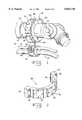
- FIG. 1is a perspective view of one embodiment of a robot arm assembly of the present invention
- FIG. 2is a perspective view of a half arm clamp of the arm clamp assembly of FIG. 1;
- FIG. 3is a side view of the half arm clamp shown in FIGS. 1 and 2;
- FIG. 4is plan view of the half arm clamp of FIGS. 1-3.
- FIG. 5is a side sectional view of the robot arm assembly of FIG. 1, with a bushing between the inner surface of the arm clamp assembly and the outer surface of the robot arm.
- a robot arm assembly 10including an arm clamp assembly 12, a robot arm 14 and an elongated element clamp 16.
- Arm clamp assembly 12(FIGS. 1-5) includes cylindrical inner surface 22 which wraps around and grasps the cylindrical outer surface 24 (FIG. 5) of robot arm 14.
- Arm clamp assembly 12includes on its periphery a plurality of mounting pads 18.
- Mounting pads 18have flat surfaces and are equidistantly spaced between ends 32.
- Each mounting pad 18includes a plurality of holes 34 to receive corresponding fasteners such as bolts (not shown) passing through elongated element clamp 16, thereby attaching elongated element clamp 16 to arm clamp assembly 12.
- Arm clamp assembly 12includes two identical, symmetrical half arm clamps 28 which are bolted together using bolts 29 (FIG. 5) passing through threaded bolt holes 30 at both ends 32 to form arm clamp assembly 12 shown in FIG. 1.
- Each half arm clamp 28exerts a grasping force on bushing 26, and, in turn, robot arm 14.
- Each half arm clamp 28is symmetrical about two different planes which divide it into four symmetrical quadrants. The first plane is equidistant from the two ends and bisects half arm clamp 28. The second plane runs through both of the two ends, the inner surface and the periphery, and bisects half arm clamp 28.
- An elongated element clamp 16carries at least one elongated element 20 which attaches to or is used in association with a tool carried by robot arm 14. A plurality of elongated element clamps 16 may be attached to a respective mounting pad 18.
- Elongated element clamp 16 shown in FIG. 1includes a clam shell arrangement wherein two elongated elements 20 are retained. Fastener 36 is latched to hold elongated element clamp 16 closed.
- Elongated element(s) 20may be in the form of electric cables, wires, hydraulic hoses and fluid conduits or the like.
- Bushing 26is disposed between and interconnects inner surface 22 of arm clamp assembly 12 and outer surface 24 of robot arm 14.
- Bushing 26may be formed from a compressible material to ensure that arm clamp assembly 12 exerts a tight, secure grasping force on robot arm 14 when the inside diameter of arm clamp assembly 12 exceeds the outside diameter of robot arm 14, or when robot arm 14 has a non-circular cross section.
- inner surface 22 of arm clamp assembly 12 and outer surface 24 of robot arm 14are generally cylindrically shaped.
- arm clamp assembly 12 and robot arm 14could be other than cylindrically shaped.
- arm clamp assembly 12could be shaped to conform to non-cylindrically shaped robot arm 14.
- compressible bushing 26could accommodate an irregularly shaped robot arm 14.
- elongated element clamps 16other than the clam shell type shown could be used.
- elongated elements 20could be passed through a single or several attached retainer rings.
Landscapes
- Engineering & Computer Science (AREA)
- Robotics (AREA)
- Mechanical Engineering (AREA)
- Manipulator (AREA)
Abstract
Description
1. Field of the Invention
The present invention relates to a robot arm assembly for organizing and directing electrical cables and fluid conduits associated with a robot arm.
2. Description of the Related Art
A robot arm assembly may include a single clamp extending from a robot arm to guide cables, hoses and the like. The single clamp may include a ring welded to a fastener arm. Cables are passed through the ring and remain confined to the area within the ring.
It is also known to organize and guide a plurality of cables or hoses with a cable retainer assembly. In this arrangement, cables are clamped in grooves by opposing plates such that the cables remain parallel and do not rub together. A problem with this type of cable guide is that it is difficult to securely and quickly attach these clamps and guides to the robot arm. Another problem is that these clamps and guides cannot be easily moved to various locations around the periphery of the robot arm to accommodate changes in the programmed movements of the robot arm. Yet another problem is that these clamps and guides cannot easily be attached to different shapes and sizes of robot arms. An example of such a cable guide is disclosed by U.S. Pat. No. 4,659,279 (Akeel et al.).
What is needed in the art is a system for organizing and directing electrical cables and fluid conduits associated with a robot arm that is easy to assemble, securely fastens to different shapes and sizes of robot arms, can be attached to various sides of the robot arms to accommodate changes in the programmed movements of the robot arm, and can hold a large number of cables and conduits at the same point along the length of the robot arm.
The present invention provides a robot arm assembly for organizing and directing a plurality of electrical cables and fluid conduits associated with a robot arm.
The invention comprises, in one form thereof, a robot arm assembly including a plurality of elongated elements for attachment with a tool carried by the robot arm assembly. The robot arm assembly includes a robot arm, an arm clamp assembly clamped around the robot arm, and at least one elongated element clamp. The elongated element clamp is connected to a mounting pad on the arm clamp and carries the elongated elements.
An advantage of the present invention is that the arm clamp assembly may be securely and quickly attached to the robot arm. The two identical, symmetrical half arm clamps which make up the arm clamp assembly mate around the robot arm and exert a grasping force which can be adjusted to the desired level. The symmetry and substantially identical form of the half arm clamps allows for greater interchangability of parts and assembly with less regard for the orientation of the half arm clamps.
Another advantage is that the elongated element clamp can be easily moved to various mounting pads around the periphery of the arm clamp assembly, and thereby to various locations around the outer surface of the robot arm to accommodate changes in the programmed movements of the robot arm.
Yet another advantage is that by virtue of the multiple mounting pads around the periphery of the arm clamp assembly, multiple elongated element clamps, each carrying at least one elongated element, may be attached to the arm clamp assembly at the same point along the length of the robot arm.
A further advantage is that the arm clamp assembly can easily be attached to different shapes and sizes of robot arms by virtue of the bushing disposed between and interconnecting the inner surface of the arm clamp assembly and the outer surface of the robot arm.
The above-mentioned and other features and advantages of this invention, and the manner of attaining them, will become more apparent and the invention will be better understood by reference to the following description of embodiments of the invention taken in conjunction with the accompanying drawings, wherein:
FIG. 1 is a perspective view of one embodiment of a robot arm assembly of the present invention;
FIG. 2 is a perspective view of a half arm clamp of the arm clamp assembly of FIG. 1;
FIG. 3 is a side view of the half arm clamp shown in FIGS. 1 and 2;
FIG. 4 is plan view of the half arm clamp of FIGS. 1-3; and
FIG. 5 is a side sectional view of the robot arm assembly of FIG. 1, with a bushing between the inner surface of the arm clamp assembly and the outer surface of the robot arm.
Corresponding reference characters indicate corresponding parts throughout the several views. The exemplification set out herein illustrate one preferred embodiment of the invention, in one form, and such exemplification is not to be construed as limiting the scope of the invention in any manner.
Referring now to the drawings and particularly to FIG. 1, there is shown arobot arm assembly 10 including anarm clamp assembly 12, arobot arm 14 and anelongated element clamp 16.
Arm clamp assembly 12 (FIGS. 1-5) includes cylindricalinner surface 22 which wraps around and grasps the cylindrical outer surface 24 (FIG. 5) ofrobot arm 14.Arm clamp assembly 12 includes on its periphery a plurality ofmounting pads 18.Mounting pads 18 have flat surfaces and are equidistantly spaced betweenends 32. Eachmounting pad 18 includes a plurality ofholes 34 to receive corresponding fasteners such as bolts (not shown) passing throughelongated element clamp 16, thereby attachingelongated element clamp 16 toarm clamp assembly 12.
Anelongated element clamp 16 carries at least oneelongated element 20 which attaches to or is used in association with a tool carried byrobot arm 14. A plurality ofelongated element clamps 16 may be attached to arespective mounting pad 18. Elongatedelement clamp 16 shown in FIG. 1 includes a clam shell arrangement wherein twoelongated elements 20 are retained.Fastener 36 is latched to holdelongated element clamp 16 closed. Elongated element(s) 20 may be in the form of electric cables, wires, hydraulic hoses and fluid conduits or the like.
Anoptional bushing 26 is disposed between and interconnectsinner surface 22 ofarm clamp assembly 12 andouter surface 24 ofrobot arm 14.Bushing 26 may be formed from a compressible material to ensure thatarm clamp assembly 12 exerts a tight, secure grasping force onrobot arm 14 when the inside diameter ofarm clamp assembly 12 exceeds the outside diameter ofrobot arm 14, or whenrobot arm 14 has a non-circular cross section.
In the embodiment shown in the drawings,inner surface 22 ofarm clamp assembly 12 andouter surface 24 ofrobot arm 14 are generally cylindrically shaped. However, it is to be understood thatarm clamp assembly 12 androbot arm 14 could be other than cylindrically shaped. For example,arm clamp assembly 12 could be shaped to conform to non-cylindrically shapedrobot arm 14. Alternatively,compressible bushing 26 could accommodate an irregularlyshaped robot arm 14.
Moreover, different kinds ofelongated element clamps 16 other than the clam shell type shown could be used. For instance,elongated elements 20 could be passed through a single or several attached retainer rings.
While this invention has been described as having a preferred design, the present invention can be further modified within the spirit and scope of this disclosure. This application is therefore intended to cover any variations, uses, or adaptations of the invention using its general principles. Further, this application is intended to cover such departures from the present disclosure as come within known or customary practice in the art to which this invention pertains and which fall within the limits of the appended claims.
Claims (11)
1. A robot arm assembly including a plurality of elongated elements for attachment with a tool configured to be carried by said robot arm assembly, said robot arm assembly comprising:
a robot arm;
an arm clamp assembly being clamped around said robot arm, said arm clamp assembly having a periphery and a plurality of mounting pads equidistantly spaced on said periphery; and
at least one elongated element clamp attached to a corresponding said mounting pad, said at least one elongated element clamp being configured to carry at least one of the elongated elements.
2. A robot arm assembly, comprising:
a robot arm;
an arm clamp assembly being clamped around said robot arm, said arm clamp assembly having a periphery and a plurality of mounting pads in spaced apart relation on said periphery;
at least one elongated element clamp attached to a corresponding said mounting pad; and
a plurality of elongated elements carried by said at least one elongated element clamp, each said elongated element respectively comprising one of an electrical cable, an electrical wire, a hydraulic hose and a fluid conduit.
3. The robot arm assembly of claim 2, wherein said arm clamp assembly has an inner surface and said robot arm has an outer surface, said inner surface exerting a grasping force on said robot arm.
4. The robot arm assembly of claim 3, further comprising a bushing disposed between and interconnecting said inner surface of said arm clamp assembly and said outer surface of said robot arm.
5. The robot arm assembly of claim 3, wherein said inner surface and outer surface are generally cylindrical in shape.
6. The robot arm assembly of claim 2, wherein said plurality of mounting pads are on the periphery of said arm clamp assembly.
7. The robot arm assembly of claim 2, wherein said arm clamp assembly comprises two half arm clamps, each of said half arm clamps being substantially identical and having two ends, said half arm clamps being joined together at said ends.
8. The robot arm assembly of claim 7, wherein said ends include at least one bolt hole.
9. The robot arm assembly of claim 8, wherein said two substantially identical half arm clamps are joined together with at least one bolt projecting through a respective said bolt hole.
10. The robot arm assembly of claim 8, wherein said at least one bolt hole is threaded.
11. The robot arm assembly of claim 2, wherein said plurality of mounting pads are flat.
Priority Applications (1)
| Application Number | Priority Date | Filing Date | Title |
|---|---|---|---|
| US08/821,766US5816736A (en) | 1997-03-20 | 1997-03-20 | Robot arm assembly |
Applications Claiming Priority (1)
| Application Number | Priority Date | Filing Date | Title |
|---|---|---|---|
| US08/821,766US5816736A (en) | 1997-03-20 | 1997-03-20 | Robot arm assembly |
Publications (1)
| Publication Number | Publication Date |
|---|---|
| US5816736Atrue US5816736A (en) | 1998-10-06 |
Family
ID=25234265
Family Applications (1)
| Application Number | Title | Priority Date | Filing Date |
|---|---|---|---|
| US08/821,766Expired - Fee RelatedUS5816736A (en) | 1997-03-20 | 1997-03-20 | Robot arm assembly |
Country Status (1)
| Country | Link |
|---|---|
| US (1) | US5816736A (en) |
Cited By (33)
| Publication number | Priority date | Publication date | Assignee | Title |
|---|---|---|---|---|
| DE29814416U1 (en) | 1998-08-11 | 1998-10-08 | Kuka Roboter GmbH, 86165 Augsburg | End piece for a robot protective hose |
| DE29902947U1 (en) | 1999-02-19 | 1999-07-08 | Kuka Roboter GmbH, 86165 Augsburg | Robot part |
| USD415017S (en)* | 1997-08-14 | 1999-10-12 | Holmes Products, Corp. | Clamp for attaching articles to a pole |
| US6007034A (en)* | 1997-09-30 | 1999-12-28 | Festo Ag & Co. | Device for the attachment of a sensor |
| US6349912B1 (en)* | 1999-03-27 | 2002-02-26 | De-Sta-Co Metallerzeugnisse Gmbh | Supporting structure |
| US6431018B1 (en)* | 1999-09-09 | 2002-08-13 | Fanuc Ltd. | Guide device for wiring member and/or piping member and robot with guide device |
| EP1252979A1 (en)* | 2001-04-28 | 2002-10-30 | KUKA Roboter GmbH | Device for holding cables on a robot arm comprising snap-in elements |
| US6554075B2 (en) | 2000-12-15 | 2003-04-29 | Halliburton Energy Services, Inc. | CT drilling rig |
| US20050272974A1 (en)* | 2002-10-29 | 2005-12-08 | Given Imaging Ltd. | In-vivo extendable element device and system, and method of use |
| US20060090806A1 (en)* | 2003-06-18 | 2006-05-04 | Pbm, Inc. | Sanitary conduit supports |
| US20060196300A1 (en)* | 2004-11-29 | 2006-09-07 | Fanuc Ltd | Managing device for an umbilical member of a robot and a robot having the managing device |
| USD553971S1 (en) | 2005-01-31 | 2007-10-30 | Behringer Corporation | Pipe and tube support |
| US20070253799A1 (en)* | 2006-04-27 | 2007-11-01 | Genesis Systems Group Llc | Nut runner and hexabot robot |
| US7320264B2 (en)* | 2000-07-14 | 2008-01-22 | Abb Ab | Manipulator |
| US20090146019A1 (en)* | 2007-12-10 | 2009-06-11 | Kwang Sul Choi | Cable guide device for industrial robot |
| US20100301568A1 (en)* | 2007-11-14 | 2010-12-02 | Gerhard Geyer | Tool mounting device |
| US7870688B1 (en)* | 2006-02-03 | 2011-01-18 | Night Optics USA, Inc. | Clamping device for coaxially coupling optical devices |
| US20110073728A1 (en)* | 2009-09-27 | 2011-03-31 | Blackwell Donald A | Adjustable mounting apparatus for electrical devices |
| US20120103125A1 (en)* | 2010-10-27 | 2012-05-03 | Hon Hai Precision Industry Co., Ltd. | Robot arm assembly |
| US20120292460A1 (en)* | 2011-05-19 | 2012-11-22 | Wanho T Manufacturing Co., Ltd. | Organizing device for cable and wire |
| US20150240848A1 (en)* | 2014-02-24 | 2015-08-27 | Robobuilder Co., Ltd. | Joining apparatus of module actuator |
| US9233475B2 (en) | 2012-09-26 | 2016-01-12 | Fanuc Corporation | Umbilical member attachment device of robot |
| US20160067870A1 (en)* | 2014-09-05 | 2016-03-10 | Fanuc Corporation | Umbilical member clamping device for clamping umbilical members via elastic body |
| US9438021B2 (en) | 2013-10-28 | 2016-09-06 | Wanho T Manufacturing Co., Ltd. | Organizing device for cable and wire |
| DE102016203361A1 (en)* | 2016-03-01 | 2017-09-07 | Kuka Roboter Gmbh | Industrial robot with a protective sleeve |
| US20180020651A1 (en)* | 2016-07-20 | 2018-01-25 | Harold F. Larkin | Marine Hub with Interchangeable Arms |
| DE102017107043A1 (en)* | 2017-03-31 | 2018-10-04 | Leoni Kabel Gmbh | Fastening device for a supply hose and / or a supply line for attachment to an industrial robot arm |
| US10094491B1 (en) | 2017-10-17 | 2018-10-09 | Wanho T Manufacturing Co., Ltd. | Organizing device for cable and wire |
| US10179414B2 (en)* | 2013-06-18 | 2019-01-15 | Rj Hanlon Company, Inc. | Protective ring for automated equipment axis pivot points |
| JP2021104558A (en)* | 2019-12-26 | 2021-07-26 | ファナック株式会社 | Support structure, robot, and parallel link robot |
| US20220337044A1 (en)* | 2019-09-24 | 2022-10-20 | Commscope Technologies Llc | Composite cable seal |
| CN115916486A (en)* | 2020-06-16 | 2023-04-04 | 雷斯昂公司 | Collaborative robot line management system |
| EP4424478A1 (en)* | 2023-03-01 | 2024-09-04 | Universal Robots A/S | Accessory mounting system for a robot |
Citations (18)
| Publication number | Priority date | Publication date | Assignee | Title |
|---|---|---|---|---|
| US513630A (en)* | 1894-01-30 | Detachable electric-wire-holding device | ||
| US1093235A (en)* | 1913-08-27 | 1914-04-14 | Pratt Johns Co | Trolley-wire-feed-tap insulator. |
| US1835338A (en)* | 1926-10-25 | 1931-12-08 | Rossman Patents Inc | Unit pipe clamp fittings |
| US2133197A (en)* | 1936-02-08 | 1938-10-11 | Innocenti Ferdinando | Device for uniting tubes of metallic structures |
| US2351858A (en)* | 1941-03-06 | 1944-06-20 | Titeflex Inc | Securing clamp |
| US2912482A (en)* | 1959-02-12 | 1959-11-10 | Plm Products Inc | Aerial cable support and spacer |
| US3843083A (en)* | 1972-11-09 | 1974-10-22 | Wonder Piles | Mounting apparatus for portable device |
| US3961647A (en)* | 1974-01-10 | 1976-06-08 | Doubleday Eric G | Suction pipe having means to support a supply conduit |
| US4300852A (en)* | 1978-05-23 | 1981-11-17 | The Secretary Of State For Energy In Her Britannic Majesty's Government Of The United Kingdom Of Great Britain And Northern Ireland | Underwater structural joints |
| US4507042A (en)* | 1981-10-07 | 1985-03-26 | Yaskawa Electric Mfg. Co., Ltd. | Cable support of a robot |
| US4659279A (en)* | 1984-12-24 | 1987-04-21 | Gmf Robotics Corporation | Robot with improved cable routing and clamping |
| US4688961A (en)* | 1985-03-15 | 1987-08-25 | Nifco Inc. | Combination clip |
| US4817897A (en)* | 1986-02-12 | 1989-04-04 | Ulrich Kreusel | Cross-connector to two crossing tubular elements |
| US4855560A (en)* | 1986-10-09 | 1989-08-08 | Kawasaki Jukogyo Kabushiki Kaisha | Welding robot |
| US4901970A (en)* | 1989-01-30 | 1990-02-20 | Moss Douglas M | Fishing pole holder with universally adjustable mount |
| US5060961A (en)* | 1987-11-18 | 1991-10-29 | Keith Bontrager | Mechanically joined steering assembly |
| US5437207A (en)* | 1991-03-21 | 1995-08-01 | Kuka Schweissanlegen & Roboter Gmbh | Multiaxial manipulator |
| US5443232A (en)* | 1993-05-24 | 1995-08-22 | Kesinger; Donald A. | Apparatus for hanging TV cable and the like |
- 1997
- 1997-03-20USUS08/821,766patent/US5816736A/ennot_activeExpired - Fee Related
Patent Citations (19)
| Publication number | Priority date | Publication date | Assignee | Title |
|---|---|---|---|---|
| US513630A (en)* | 1894-01-30 | Detachable electric-wire-holding device | ||
| US1093235A (en)* | 1913-08-27 | 1914-04-14 | Pratt Johns Co | Trolley-wire-feed-tap insulator. |
| US1835338A (en)* | 1926-10-25 | 1931-12-08 | Rossman Patents Inc | Unit pipe clamp fittings |
| US2133197A (en)* | 1936-02-08 | 1938-10-11 | Innocenti Ferdinando | Device for uniting tubes of metallic structures |
| US2351858A (en)* | 1941-03-06 | 1944-06-20 | Titeflex Inc | Securing clamp |
| US2912482A (en)* | 1959-02-12 | 1959-11-10 | Plm Products Inc | Aerial cable support and spacer |
| US3843083A (en)* | 1972-11-09 | 1974-10-22 | Wonder Piles | Mounting apparatus for portable device |
| US3961647A (en)* | 1974-01-10 | 1976-06-08 | Doubleday Eric G | Suction pipe having means to support a supply conduit |
| US4300852A (en)* | 1978-05-23 | 1981-11-17 | The Secretary Of State For Energy In Her Britannic Majesty's Government Of The United Kingdom Of Great Britain And Northern Ireland | Underwater structural joints |
| US4507042A (en)* | 1981-10-07 | 1985-03-26 | Yaskawa Electric Mfg. Co., Ltd. | Cable support of a robot |
| US4529352A (en)* | 1981-10-07 | 1985-07-16 | Yaskawa Electric Mfg. Co. Ltd. | Cable support of a robot |
| US4659279A (en)* | 1984-12-24 | 1987-04-21 | Gmf Robotics Corporation | Robot with improved cable routing and clamping |
| US4688961A (en)* | 1985-03-15 | 1987-08-25 | Nifco Inc. | Combination clip |
| US4817897A (en)* | 1986-02-12 | 1989-04-04 | Ulrich Kreusel | Cross-connector to two crossing tubular elements |
| US4855560A (en)* | 1986-10-09 | 1989-08-08 | Kawasaki Jukogyo Kabushiki Kaisha | Welding robot |
| US5060961A (en)* | 1987-11-18 | 1991-10-29 | Keith Bontrager | Mechanically joined steering assembly |
| US4901970A (en)* | 1989-01-30 | 1990-02-20 | Moss Douglas M | Fishing pole holder with universally adjustable mount |
| US5437207A (en)* | 1991-03-21 | 1995-08-01 | Kuka Schweissanlegen & Roboter Gmbh | Multiaxial manipulator |
| US5443232A (en)* | 1993-05-24 | 1995-08-22 | Kesinger; Donald A. | Apparatus for hanging TV cable and the like |
Cited By (51)
| Publication number | Priority date | Publication date | Assignee | Title |
|---|---|---|---|---|
| USD415017S (en)* | 1997-08-14 | 1999-10-12 | Holmes Products, Corp. | Clamp for attaching articles to a pole |
| US6007034A (en)* | 1997-09-30 | 1999-12-28 | Festo Ag & Co. | Device for the attachment of a sensor |
| DE29814416U1 (en) | 1998-08-11 | 1998-10-08 | Kuka Roboter GmbH, 86165 Augsburg | End piece for a robot protective hose |
| DE29902947U1 (en) | 1999-02-19 | 1999-07-08 | Kuka Roboter GmbH, 86165 Augsburg | Robot part |
| EP1029638A1 (en)* | 1999-02-19 | 2000-08-23 | KUKA Roboter GmbH | Robot member with a support for hoses |
| US6349912B1 (en)* | 1999-03-27 | 2002-02-26 | De-Sta-Co Metallerzeugnisse Gmbh | Supporting structure |
| US6431018B1 (en)* | 1999-09-09 | 2002-08-13 | Fanuc Ltd. | Guide device for wiring member and/or piping member and robot with guide device |
| US7320264B2 (en)* | 2000-07-14 | 2008-01-22 | Abb Ab | Manipulator |
| US6554075B2 (en) | 2000-12-15 | 2003-04-29 | Halliburton Energy Services, Inc. | CT drilling rig |
| US6719062B2 (en) | 2000-12-15 | 2004-04-13 | Halliburton Energy Services, Inc. | CT drilling rig |
| EP1252979A1 (en)* | 2001-04-28 | 2002-10-30 | KUKA Roboter GmbH | Device for holding cables on a robot arm comprising snap-in elements |
| US20050272974A1 (en)* | 2002-10-29 | 2005-12-08 | Given Imaging Ltd. | In-vivo extendable element device and system, and method of use |
| US20060090805A1 (en)* | 2003-06-18 | 2006-05-04 | Pbm, Inc. | Methods for supporting conduits in a sanitary environment |
| US20060090806A1 (en)* | 2003-06-18 | 2006-05-04 | Pbm, Inc. | Sanitary conduit supports |
| US7367363B2 (en) | 2003-06-18 | 2008-05-06 | Pbm, Inc. | Sanitary conduit support systems |
| US7481247B2 (en) | 2003-06-18 | 2009-01-27 | Stauff Corporation | Sanitary conduit supports |
| US7543606B2 (en) | 2003-06-18 | 2009-06-09 | Stauff Corporation | Methods for supporting conduits in a sanitary environment |
| US20060196300A1 (en)* | 2004-11-29 | 2006-09-07 | Fanuc Ltd | Managing device for an umbilical member of a robot and a robot having the managing device |
| USD553971S1 (en) | 2005-01-31 | 2007-10-30 | Behringer Corporation | Pipe and tube support |
| US7870688B1 (en)* | 2006-02-03 | 2011-01-18 | Night Optics USA, Inc. | Clamping device for coaxially coupling optical devices |
| US20070253799A1 (en)* | 2006-04-27 | 2007-11-01 | Genesis Systems Group Llc | Nut runner and hexabot robot |
| US7673384B2 (en)* | 2006-04-27 | 2010-03-09 | Genesis Systems Group, Llc | Nut runner and hexabot robot |
| US20100301568A1 (en)* | 2007-11-14 | 2010-12-02 | Gerhard Geyer | Tool mounting device |
| US8360377B2 (en)* | 2007-11-14 | 2013-01-29 | Staeubli Tec-Systems Gmbh | Tool mounting device |
| US20090146019A1 (en)* | 2007-12-10 | 2009-06-11 | Kwang Sul Choi | Cable guide device for industrial robot |
| US7546985B1 (en)* | 2007-12-10 | 2009-06-16 | Kwang Sul Choi | Cable guide device for industrial robot |
| US8079560B2 (en)* | 2009-09-27 | 2011-12-20 | Donald A. Blackwell | Adjustable mounting apparatus for electrical devices |
| US20110073728A1 (en)* | 2009-09-27 | 2011-03-31 | Blackwell Donald A | Adjustable mounting apparatus for electrical devices |
| US20120103125A1 (en)* | 2010-10-27 | 2012-05-03 | Hon Hai Precision Industry Co., Ltd. | Robot arm assembly |
| US8544359B2 (en)* | 2010-10-27 | 2013-10-01 | Hong Fu Jin Precision Industry (Shenzhen) Co., Ltd. | Robot arm assembly |
| US20120292460A1 (en)* | 2011-05-19 | 2012-11-22 | Wanho T Manufacturing Co., Ltd. | Organizing device for cable and wire |
| US9233475B2 (en) | 2012-09-26 | 2016-01-12 | Fanuc Corporation | Umbilical member attachment device of robot |
| US10179414B2 (en)* | 2013-06-18 | 2019-01-15 | Rj Hanlon Company, Inc. | Protective ring for automated equipment axis pivot points |
| US9438021B2 (en) | 2013-10-28 | 2016-09-06 | Wanho T Manufacturing Co., Ltd. | Organizing device for cable and wire |
| US20150240848A1 (en)* | 2014-02-24 | 2015-08-27 | Robobuilder Co., Ltd. | Joining apparatus of module actuator |
| US20160067870A1 (en)* | 2014-09-05 | 2016-03-10 | Fanuc Corporation | Umbilical member clamping device for clamping umbilical members via elastic body |
| US9751219B2 (en)* | 2014-09-05 | 2017-09-05 | Fanuc Corporation | Umbilical member clamping device for clamping umbilical members via elastic body |
| DE102016203361A1 (en)* | 2016-03-01 | 2017-09-07 | Kuka Roboter Gmbh | Industrial robot with a protective sleeve |
| US20180020651A1 (en)* | 2016-07-20 | 2018-01-25 | Harold F. Larkin | Marine Hub with Interchangeable Arms |
| US10588305B2 (en)* | 2016-07-20 | 2020-03-17 | Harold F. Larkin | Marine hub with interchangeable arms |
| WO2018177482A1 (en)* | 2017-03-31 | 2018-10-04 | Leoni Kabel Gmbh | Attaching device for a supply pipe and/or supply line for attaching to an industrial robot arm |
| DE102017107043A1 (en)* | 2017-03-31 | 2018-10-04 | Leoni Kabel Gmbh | Fastening device for a supply hose and / or a supply line for attachment to an industrial robot arm |
| US11446830B2 (en)* | 2017-03-31 | 2022-09-20 | Bizlink Industry Germany Gmbh | Fastening device for a supply hose and/or a supply line for fastening to an industrial-robot arm |
| US10094491B1 (en) | 2017-10-17 | 2018-10-09 | Wanho T Manufacturing Co., Ltd. | Organizing device for cable and wire |
| US20220337044A1 (en)* | 2019-09-24 | 2022-10-20 | Commscope Technologies Llc | Composite cable seal |
| US12095244B2 (en)* | 2019-09-24 | 2024-09-17 | Commscope Technologies Llc | Composite cable seal |
| JP2021104558A (en)* | 2019-12-26 | 2021-07-26 | ファナック株式会社 | Support structure, robot, and parallel link robot |
| CN115916486A (en)* | 2020-06-16 | 2023-04-04 | 雷斯昂公司 | Collaborative robot line management system |
| JP2023530307A (en)* | 2020-06-16 | 2023-07-14 | レイセオン カンパニー | Collaborative robot line management system |
| US12128552B2 (en)* | 2020-06-16 | 2024-10-29 | Raytheon Company | Collaborative robot line management system |
| EP4424478A1 (en)* | 2023-03-01 | 2024-09-04 | Universal Robots A/S | Accessory mounting system for a robot |
Similar Documents
| Publication | Publication Date | Title |
|---|---|---|
| US5816736A (en) | Robot arm assembly | |
| US11732822B2 (en) | Multi-conduit flexible retention mechanism | |
| US5375798A (en) | Connector for facilitating a connection between a channel member and a support member | |
| US6533472B1 (en) | Optical fiber splice closure assembly | |
| US6111194A (en) | Electrical and/or fluid power transmitting assembly in a manipulative robot | |
| EP0276640A1 (en) | A clamp fitting, in particular for pipes and tube | |
| US3999340A (en) | Insulating cover and clamp for guy wires or covers | |
| US5225648A (en) | Industrial robot with cable arrangement system | |
| US5163643A (en) | Span clamp assembly | |
| US4461521A (en) | Strand hanger bracket with common ground connections | |
| EP4164842B1 (en) | Collaborative robot line management system | |
| US6559387B1 (en) | Universal ground clamp with S-shaped second strap | |
| US5281042A (en) | Saddle clamp assembly | |
| US11446830B2 (en) | Fastening device for a supply hose and/or a supply line for fastening to an industrial-robot arm | |
| US6145793A (en) | Robotic MIG clamp | |
| US10663087B2 (en) | Power tool cable mount | |
| US4573652A (en) | Support system for maritime or other use | |
| JPH0453907A (en) | Sheath gripping structure for optical fiber cable | |
| JPH0312008Y2 (en) | ||
| US12341329B2 (en) | Wire management device | |
| KR200223916Y1 (en) | Clamp for binding cable | |
| US4697482A (en) | Pliers gripping band | |
| KR20180064225A (en) | Apparatus for Assembling Wire-rope, and Method for Assembling Wire-rope Using The Same | |
| US6161877A (en) | Conduit interlock assembly | |
| CA1237493A (en) | Universal ground clamp |
Legal Events
| Date | Code | Title | Description |
|---|---|---|---|
| AS | Assignment | Owner name:FLEX-CABLE, INC., MICHIGAN Free format text:ASSIGNMENT OF ASSIGNORS INTEREST;ASSIGNOR:KROULIK, ERWIN K.;REEL/FRAME:008480/0247 Effective date:19970311 | |
| AS | Assignment | Owner name:INTERSERVICES, INC., ILLINOIS Free format text:ASSIGNMENT OF ASSIGNORS INTEREST;ASSIGNOR:FLEX-CABLE, INC.;REEL/FRAME:011058/0337 Effective date:20000711 | |
| FPAY | Fee payment | Year of fee payment:4 | |
| AS | Assignment | Owner name:NORTHERN CABLE & AUTOMATION, LLC, MICHIGAN Free format text:ASSIGNMENT OF ASSIGNORS INTEREST;ASSIGNOR:BALGUER CORP., DOING BUSINESS AS FLEX CABLE, INC.;REEL/FRAME:015334/0790 Effective date:20041102 | |
| REMI | Maintenance fee reminder mailed | ||
| LAPS | Lapse for failure to pay maintenance fees | ||
| STCH | Information on status: patent discontinuation | Free format text:PATENT EXPIRED DUE TO NONPAYMENT OF MAINTENANCE FEES UNDER 37 CFR 1.362 | |
| FP | Lapsed due to failure to pay maintenance fee | Effective date:20061006 |