US5816346A - Rotary drill bits and methods of designing such drill bits - Google Patents
Rotary drill bits and methods of designing such drill bitsDownload PDFInfo
- Publication number
- US5816346A US5816346AUS08/659,502US65950296AUS5816346AUS 5816346 AUS5816346 AUS 5816346AUS 65950296 AUS65950296 AUS 65950296AUS 5816346 AUS5816346 AUS 5816346A
- Authority
- US
- United States
- Prior art keywords
- cutters
- drill bit
- blades
- bit
- blade
- Prior art date
- Legal status (The legal status is an assumption and is not a legal conclusion. Google has not performed a legal analysis and makes no representation as to the accuracy of the status listed.)
- Expired - Lifetime
Links
- 238000000034methodMethods0.000titledescription3
- 230000015572biosynthetic processEffects0.000claimsabstractdescription19
- 238000005755formation reactionMethods0.000claimsabstractdescription19
- 238000005553drillingMethods0.000claimsabstractdescription16
- 238000005520cutting processMethods0.000claimsdescription7
- 229910003460diamondInorganic materials0.000claimsdescription4
- 239000010432diamondSubstances0.000claimsdescription4
- 239000000463materialSubstances0.000claimsdescription4
- 239000000758substrateSubstances0.000claimsdescription3
- 230000035515penetrationEffects0.000description10
- 239000011435rockSubstances0.000description7
- 229910000831SteelInorganic materials0.000description2
- 230000001419dependent effectEffects0.000description2
- 239000012530fluidSubstances0.000description2
- 239000010959steelSubstances0.000description2
- 230000009286beneficial effectEffects0.000description1
- 238000004140cleaningMethods0.000description1
- 238000001816coolingMethods0.000description1
- 230000007812deficiencyEffects0.000description1
- 230000014509gene expressionEffects0.000description1
- 238000004519manufacturing processMethods0.000description1
- 239000011159matrix materialSubstances0.000description1
- 229910052751metalInorganic materials0.000description1
- 239000002184metalSubstances0.000description1
- 238000012986modificationMethods0.000description1
- 230000004048modificationEffects0.000description1
- 238000004663powder metallurgyMethods0.000description1
- 230000002250progressing effectEffects0.000description1
- UONOETXJSWQNOL-UHFFFAOYSA-Ntungsten carbideChemical compound[W+]#[C-]UONOETXJSWQNOL-UHFFFAOYSA-N0.000description1
Images


Classifications
- E—FIXED CONSTRUCTIONS
- E21—EARTH OR ROCK DRILLING; MINING
- E21B—EARTH OR ROCK DRILLING; OBTAINING OIL, GAS, WATER, SOLUBLE OR MELTABLE MATERIALS OR A SLURRY OF MINERALS FROM WELLS
- E21B10/00—Drill bits
- E21B10/42—Rotary drag type drill bits with teeth, blades or like cutting elements, e.g. fork-type bits, fish tail bits
- E21B10/43—Rotary drag type drill bits with teeth, blades or like cutting elements, e.g. fork-type bits, fish tail bits characterised by the arrangement of teeth or other cutting elements
- E—FIXED CONSTRUCTIONS
- E21—EARTH OR ROCK DRILLING; MINING
- E21B—EARTH OR ROCK DRILLING; OBTAINING OIL, GAS, WATER, SOLUBLE OR MELTABLE MATERIALS OR A SLURRY OF MINERALS FROM WELLS
- E21B10/00—Drill bits
- E21B10/46—Drill bits characterised by wear resisting parts, e.g. diamond inserts
- E21B10/54—Drill bits characterised by wear resisting parts, e.g. diamond inserts the bit being of the rotary drag type, e.g. fork-type bits
- E21B10/55—Drill bits characterised by wear resisting parts, e.g. diamond inserts the bit being of the rotary drag type, e.g. fork-type bits with preformed cutting elements
Definitions
- the inventionrelates to rotary drill bits for drilling or coring holes in subsurface formations and, more particularly, to drag type drill bits that have cutters thereon of differing sizes.
- Rotary drill bitsusually comprise a bit body having a shank for connection to a drill string, a plurality of circumferentially spaced blades on the bit body each extending outwardly away from the central axis of rotation of the bit, and a plurality of cutters mounted along each blade.
- these drill bitsat least two sizes of cutters are used thereon to provide a duality of purpose or benefit not found in drill bits having all the same sized cutters.
- One specific example of a drill bit having large and small cuttersis disclosed in U.S. Pat. No. 5,222,566, which is commonly assigned hereto, and which is hereby incorporated by reference. In the '566 Patent the drill bit has large cutters on the blades with greater radial extent, i.e.
- the bladesare arranged so that the smaller or shorter blades have less sweep angle proportionately than the larger or longer blades.
- radial gap from a front face of a longer blade to a front face of a trailing shorter bladeis less than the radial gap from a front face of a shorter blade to a front face of a trailing longer blade.
- a problem encountered with small/large cutter drill bitsis that the rate of penetration (ROP) is primarily dependent upon the size of the small cutters, with the ROP for a small cutter drill bit being less than for a large cutter drill bit for a soft formation. To increase the ROP, larger cutters than desired had to be used.
- a second problem encountered with small/large cutter drill bitsis that the torque response of the drill bit is primarily dependent upon the size of the large cutters. For large cutters, the torque can rapidly increase and decrease which can severely damage the fragile polycrystalline diamond compacts (PDC) used as the cutter faces. In order to smooth the torque response and increase the life of the cutters, smaller cutters than desired had to be used.
- the present inventioncomprises a rotary drill bit for drilling subsurface formations with a bit body having a shank for connection to a drill string.
- a plurality of primary blades and at least one secondary bladeare circumferentially spaced and extend outwardly away from a central axis of rotation of the bit.
- a plurality of cuttersare mounted along each blade with a majority of the cutters mounted on each of the primary blades having a greater exposure than a majority of the cutters on the secondary blade. Further, a sweep angle of the secondary blade is less than a sweep angle of the primary blades.
- ROPrate of penetration
- the drill bitwill exhibit a rate of penetration (ROP) as a function of the size of the cutters on the primary blades.
- ROPrate of penetration
- the drill bitwill have a greater rate of penetration that a comparable drill bit having primarily smaller sized cutters.
- the drill bitwill have a relatively low torque profile, since its torque characteristics will be determined as a function of the smaller sized cutters on the at least one secondary blade, and not by the larger cutters.
- FIG. 1is an elevational view of one preferred embodiment of a drill bit of the present invention.
- FIG. 2is a schematic side elevational view of the cutter tip profile, and body profiles of small and large cutters on a drill bit of the present invention.
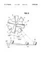
- FIG. 3is a diagrammatic view of a drill bit of the present invention showing relative distance of sweep for differing sized cutters.
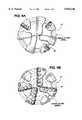
- FIG. 4is an elevational view of a drill bit of the present invention with lines showing two distinct spiral cutter layouts.
- FIG. 5is a schematic side elevational view of the cutter layout for small and large cutters on a drill bit of the present invention, and showing the differing number of small cutters that may overlap the gap between adjacent large cutters.
- FIG. 6is a table showing the volume of rock removed for certain cutters on an example drill bit of the present invention.
- FIGS. 7A and 7Bare schematic side views of the cutters on a large blade and on a short blade to show the cutter spacing.
- a drill bit of the present inventioncomprises a bit body 10 machined from metal, usually steel, which may be hard faced. Alternatively the bit body 10, or a part thereof, may be molded from matrix material using a powder metallurgy process. The methods of manufacturing drill bits of this general type are well known in the art and will not be described in detail.
- a threaded steel shankextends from the bit body 10 for interconnection to a drill string, as is well known to those skilled in the art.
- On the bit body 10are formed four primary "longer” or “large” blades 12 and three secondary “shorter” or “small” blades 14. The blades 12 and 14 extend generally radially with respect to the bit axis 16 and are spaced around the circumference of the bit body.
- Relatively large cutters 18are spaced apart side-by-side along each long blade 12 and relatively small cutters 20 are spaced apart side-by-side along each short blade 14.
- the cutters 18are 13 mm in diameter and the cutters 20 are 8 mm in diameter.
- Each cutter 18, 20is generally cylindrical and of circular cross section.
- each cutter 18, 20includes a preform cutting element comprising a facing table of polycrystalline diamond or other superhard material bonded to a substrate of less hard material, such as cemented tungsten carbide.
- the cutting elementmay be bonded to a support post or stud which is received in a socket in the bit body 10 or the substrate itself may be of sufficient length that it may be directly received in a socket in the bit body.
- Such preform cutting elementsare often circular in form although the invention includes within its scope the use of cutting elements of other configurations.
- the cutters 18, 20 on the various blades 12, 14are located at different radial distances from the bit axis 16 so that the cutters together define a cutting profile which, in use, covers substantially the whole of the bottom of the bore hole being drilled.
- the cuttersit is common for the cutters to be so positioned on the blades that they form a generally spiral array so that the path swept by each cutter partly overlaps the paths swept by the cutters which are at slightly smaller and slightly greater radial distances from the bit axis.
- the bit body 10is formed with a central passage which communicates through subsidiary passages with nozzles 22 mounted at the surface of the bit body 10.
- drilling fluid under pressureis delivered to the nozzles 22 through the internal passages and flows outwardly through spaces 24 between adjacent blades 12, 14 for cooling and cleaning the cutters 18, 20.
- the spaces 24lead to relatively large junk slots 26 and to relatively small junk slots 28 through which the drilling fluid flows upwardly through the annulus between the drill string and the surrounding formation.
- the inventor hereofhas found an important design feature that relates the cutter exposure to cutter size and to blade angle.
- the small cutters 20are set within the blades to have less exposure than the large cutters 18.
- "Exposure”is defined as the distance of cutter tip edge to the blade surface measured perpendicularly to the blade surface.
- the exposure of the large cuttersis Yl whereas the cutter exposure of the small cutters is Ys, with Yl being greater than Ys.
- the small cutters 20have a diameter of 8 mm and an exposure of from about 4.0 mm to about 6.0 mm, and the large cutters 18 have a diameter of 13 mm and an exposure of from about 5.5 mm to about 7.0 mm.
- the sweep angles of the bladesare chosen so that the small blades 14 have less sweep angle than the large blades 12.
- radial gap from a front face of a longer blade to a front face of a trailing shorter bladeis less than the radial gap from a front face of a shorter blade to a front face of a trailing longer blade. This means that the rotary distance the large cutters travel is greater than the small cutters to contact formation material left by the preceding blade.
- the difference in sweep angle of the small blades 14is X whereas the sweep angle of the large blades 12 is from about 1.1X to 2X, with about 1.3X to 1.7X being most preferred.
- thisrelates to a blade angle of from about 41 to about 45 degrees for the small blades 14 and from about 55 degrees to about 66 degrees for the large blades 12.
- the small cutters 20have greater exposure in proportion to the small cutter's diameter than the large cutters 18.
- the small cutters 20are 8 mm in diameter and have an exposure of 5 mm
- the large cutters 18are 13 mm in diameter and have an exposure of 7 mm. So, in this example 5 mm/8 mm is greater than 7 mm/13 mm.
- the above described differences and relationships of cutter exposure combined with the differences and relationships in blade sweep angleenable the drill bit of the present invention to have a ROP performance characteristics that is not limited by the size of the small cutters.
- a 61/2" seven bladed drill bit with 8 mm and 13 mm cuttershas a sweep angle for the small blades of 41.5 degrees and a sweep angle of 55.0 degrees for the large blades.
- the 13 mm cuttersset a depth of penetration of 0.256" per revolution and the 8 mm cutters set a depth of penetration of 0.200" per revolution.
- the drill bit of the present inventionhas a ROP not limited by the smaller cutters, as was a problem with prior drill bits.
- the cutters on drag type of drill bitsare arranged in a spiral pattern to ensure that the entire bottom pattern of the borehole is cut by the cutters.
- the cutter order starting from the bit axis and progressing outwardly to the bit gaugemay progress across blades 1, 3, 5, 7, 2, 4, 6, or any other desired repeating pattern of blade numbers.
- the inventor hereofhas found that a drill bit can have at least two distinct and independent spiral patterns to improve the torque response.
- the drill bit 10has a first spiral pattern 30 for the large cutters 18 and a second distinct and independent spiral pattern 32 for the small cutters 20.
- the spiral patterns 30, 32may or may not have a repeating pattern, but it has been found desirable for these patterns 30, 32 to have repeating patterns.
- the blade number repeating pattern for the large cutter spiral 30is 1, 3, 5, 7, 1, 3, 5, 7 etc.
- the small cutter spiral 32is 2, 4, 6, 2, 4, 6, etc.
- the frequency of the small cutter pattern 32is greater than the frequency of the large cutter pattern 30. It is preferred that the frequency of the small cutter pattern be X and the frequency of the large cutter pattern be from about 1/3 X to about 2/3 X.
- This frequencyis a function of the spacing of adjacent cutters, rather than the sweep angles.
- the reason that the small cutter spiral order has a higher frequencyis because the cutters can be packed closer together than the large cutters. Therefore, since the cutters are packed closer together, and they are smaller, then the small cutter spiral order will repeat more frequently, ie. a higher frequency.
- the inventor hereofhas found that the number of small cutters that fit within the cutter tip gap of the large cutters can vary.
- the number of small cutters that fit within the cutter tip gap of the large cuttersvaries due to the presence of two different spiral orders and the basic geometry of the bit.
- the "cutter tip gap”is defined as the distance between the cutter tip radius position of two overlapping cutters.
- the inventor hereofhas determined that the cutters and the blades are arranged so that the volumes of the rock removed by the cutters are approximately equal.
- the determination of the volume of rock removed for any cuttercan be easily completed by algorithms that are well known to those skilled in the art.
- the inventorWith a drill bit of the differing sized cutters and/or blades, the inventor has found it beneficial to have the volume of rock removed to be similar for adjacent cutters regardless of the angular spacing of the blade. For example, when a large cutter on blade number 5 is followed in the cutter order by a small cutter on blade 4, the radial distance along the bit profile or space between the large and the small cutter is minimized to try to equalize the volume of rock removed.
- FIG. 6provides a table that has the cutter size, cutter radius position and volume of rock removed for the 61/2" example drill bit described previously herein above. By looking at the table of FIG. 6, one skilled in the art will see that the volume factor of the large cutters and the small cutters are approximately equal as compared to the volume factors of adjacent cutters on prior bits.
- FIGS. 7A and 7Billustrate another feature of the present invention to reduce torque and thereby increase the cutter life, wherein the distance between adjacent cutters on the same blade is approximately equal from blade to blade. Additionally, the distance between adjacent cutters on the same blade is approximately equal regardless of cutter diameter.
- FIG. 7Ashows the distance between large cutters 18 on a large blade 12 is Dl, which is approximately equal to Ds, which is the distance between small cutters 20 on a small blade 14. In the previously used example for a 61/2" bit with 8 mm and 13 mm cutters, the distance Dl is from about 0.035 inches to about 0.090 inches, and the distance Ds is from about 0.035 inches to about 0.080 inches.
- the drill bit of the present inventionhas an asymmetric blade layout which enhances bit stability and therefore promotes good directional drilling characteristics.
- the combination of tightly packed 13 mm and 8 mm cuttersproduces a seven bladed bit design with a cutter count equivalent to an eight bladed bit that uses only 10 mm cutters.
- the drill bit of the present inventionhas a higher ROP and less torque than comparable bits with single sized cutters as well as comparable two-sized cutter bits.
Landscapes
- Engineering & Computer Science (AREA)
- Life Sciences & Earth Sciences (AREA)
- Geology (AREA)
- Mining & Mineral Resources (AREA)
- Mechanical Engineering (AREA)
- Physics & Mathematics (AREA)
- Environmental & Geological Engineering (AREA)
- Fluid Mechanics (AREA)
- General Life Sciences & Earth Sciences (AREA)
- Geochemistry & Mineralogy (AREA)
- Earth Drilling (AREA)
Abstract
Description
Claims (37)
Priority Applications (1)
| Application Number | Priority Date | Filing Date | Title |
|---|---|---|---|
| US08/659,502US5816346A (en) | 1996-06-06 | 1996-06-06 | Rotary drill bits and methods of designing such drill bits |
Applications Claiming Priority (1)
| Application Number | Priority Date | Filing Date | Title |
|---|---|---|---|
| US08/659,502US5816346A (en) | 1996-06-06 | 1996-06-06 | Rotary drill bits and methods of designing such drill bits |
Publications (1)
| Publication Number | Publication Date |
|---|---|
| US5816346Atrue US5816346A (en) | 1998-10-06 |
Family
ID=24645660
Family Applications (1)
| Application Number | Title | Priority Date | Filing Date |
|---|---|---|---|
| US08/659,502Expired - LifetimeUS5816346A (en) | 1996-06-06 | 1996-06-06 | Rotary drill bits and methods of designing such drill bits |
Country Status (1)
| Country | Link |
|---|---|
| US (1) | US5816346A (en) |
Cited By (35)
| Publication number | Priority date | Publication date | Assignee | Title |
|---|---|---|---|---|
| US6065553A (en)* | 1997-08-20 | 2000-05-23 | Camco International (Uk) Limited | Split blade rotary drag type drill bits |
| EP0874127A3 (en)* | 1997-04-21 | 2000-08-02 | Camco International (UK) Limited | Rotary drill bits with blades and nozzles |
| US6123161A (en)* | 1997-06-14 | 2000-09-26 | Camco International (Uk) Limited | Rotary drill bits |
| US6230827B1 (en) | 1997-09-19 | 2001-05-15 | Baker Hughes Incorporated | Earth-boring drill bits with enhanced formation cuttings removal features and methods of drilling |
| US6283233B1 (en)* | 1996-12-16 | 2001-09-04 | Dresser Industries, Inc | Drilling and/or coring tool |
| US20020157869A1 (en)* | 2001-03-26 | 2002-10-31 | Halliburton Energy Services, Inc. | Rock drill bits, methods, and systems with transition-optimized torque distribution |
| US6536543B2 (en)* | 2000-12-06 | 2003-03-25 | Baker Hughes Incorporated | Rotary drill bits exhibiting sequences of substantially continuously variable cutter backrake angles |
| US20060206233A1 (en)* | 2005-03-09 | 2006-09-14 | Carpenter David A | Method and apparatus for cutting a workpiece |
| US20070240905A1 (en)* | 2006-04-18 | 2007-10-18 | Varel International, Ltd. | Drill bit with multiple cutter geometries |
| US20070261890A1 (en)* | 2006-05-10 | 2007-11-15 | Smith International, Inc. | Fixed Cutter Bit With Centrally Positioned Backup Cutter Elements |
| US20080105466A1 (en)* | 2006-10-02 | 2008-05-08 | Hoffmaster Carl M | Drag Bits with Dropping Tendencies and Methods for Making the Same |
| US20080135297A1 (en)* | 2006-12-07 | 2008-06-12 | David Gavia | Rotary drag bits having a pilot cutter configuraton and method to pre-fracture subterranean formations therewith |
| US20080179108A1 (en)* | 2007-01-25 | 2008-07-31 | Mcclain Eric E | Rotary drag bit and methods therefor |
| US20080302575A1 (en)* | 2007-06-11 | 2008-12-11 | Smith International, Inc. | Fixed Cutter Bit With Backup Cutter Elements on Primary Blades |
| US20090138242A1 (en)* | 2007-11-27 | 2009-05-28 | Schlumberger Technology Corporation | Minimizing stick-slip while drilling |
| US20090145669A1 (en)* | 2007-12-07 | 2009-06-11 | Smith International, Inc. | Drill Bit Cutting Structure and Methods to Maximize Depth-0f-Cut For Weight on Bit Applied |
| US20090266619A1 (en)* | 2008-04-01 | 2009-10-29 | Smith International, Inc. | Fixed Cutter Bit With Backup Cutter Elements on Secondary Blades |
| US20100025121A1 (en)* | 2008-07-30 | 2010-02-04 | Thorsten Schwefe | Earth boring drill bits with using opposed kerfing for cutters |
| US20100089658A1 (en)* | 2008-10-13 | 2010-04-15 | Baker Hughes Incorporated | Drill bit with continuously sharp edge cutting elements |
| US20100089661A1 (en)* | 2008-10-13 | 2010-04-15 | Baker Hughes Incorporated | Drill bit with continuously sharp edge cutting elements |
| US20100089649A1 (en)* | 2008-10-13 | 2010-04-15 | Baker Hughes Incorporated | Drill bit with continuously sharp edge cutting elements |
| US20100089664A1 (en)* | 2008-10-13 | 2010-04-15 | Baker Hughes Incorporated | Drill bit with continuously sharp edge cutting elements |
| US20100322533A1 (en)* | 2009-06-18 | 2010-12-23 | Smith International, Inc. | Cyclic Noise Removal in Borehole Imaging |
| US20110024200A1 (en)* | 2009-07-08 | 2011-02-03 | Baker Hughes Incorporated | Cutting element and method of forming thereof |
| US20110038559A1 (en)* | 2009-06-18 | 2011-02-17 | Smith International, Inc. | Cyclic noise removal in borehole imaging |
| US20130098688A1 (en)* | 2011-10-18 | 2013-04-25 | Smith International, Inc. | Drill bits having rotating cutting structures thereon |
| US8500833B2 (en) | 2009-07-27 | 2013-08-06 | Baker Hughes Incorporated | Abrasive article and method of forming |
| US8887839B2 (en) | 2009-06-25 | 2014-11-18 | Baker Hughes Incorporated | Drill bit for use in drilling subterranean formations |
| EP2519705A4 (en)* | 2009-12-28 | 2015-03-04 | Baker Hughes Inc | Earth-boring tools having differing cutting elements on a blade and related methods |
| US8978788B2 (en) | 2009-07-08 | 2015-03-17 | Baker Hughes Incorporated | Cutting element for a drill bit used in drilling subterranean formations |
| US9903162B2 (en)* | 2011-12-29 | 2018-02-27 | Smith International, Inc. | Spacing of rolling cutters on a fixed cutter bit |
| US10017998B2 (en) | 2012-02-08 | 2018-07-10 | Baker Hughes Incorporated | Drill bits and earth-boring tools including shaped cutting elements and associated methods |
| US20190195024A1 (en)* | 2013-12-18 | 2019-06-27 | Halliburton Energy Services, Inc. | Cutting structure design with secondary cutter methodology |
| US10344537B2 (en)* | 2016-07-28 | 2019-07-09 | Baker Hughes Incorporated | Earth-boring tools, methods of forming earth-boring tools, and methods of forming a borehole in a subterranean formation |
| US20240392629A1 (en)* | 2023-05-26 | 2024-11-28 | Baker Hughes Oilfield Operations Llc | Casing drill bit facilitating drill-out thereof, and related methods of manufacture and use |
Citations (6)
| Publication number | Priority date | Publication date | Assignee | Title |
|---|---|---|---|---|
| US5222566A (en)* | 1991-02-01 | 1993-06-29 | Camco Drilling Group Ltd. | Rotary drill bits and methods of designing such drill bits |
| US5244039A (en)* | 1991-10-31 | 1993-09-14 | Camco Drilling Group Ltd. | Rotary drill bits |
| US5346025A (en)* | 1991-12-30 | 1994-09-13 | Dresser Industries, Inc. | Drill bit with improved insert cutter pattern and method of drilling |
| US5549171A (en)* | 1994-08-10 | 1996-08-27 | Smith International, Inc. | Drill bit with performance-improving cutting structure |
| US5607024A (en)* | 1995-03-07 | 1997-03-04 | Smith International, Inc. | Stability enhanced drill bit and cutting structure having zones of varying wear resistance |
| US5607025A (en)* | 1995-06-05 | 1997-03-04 | Smith International, Inc. | Drill bit and cutting structure having enhanced placement and sizing of cutters for improved bit stabilization |
- 1996
- 1996-06-06USUS08/659,502patent/US5816346A/ennot_activeExpired - Lifetime
Patent Citations (6)
| Publication number | Priority date | Publication date | Assignee | Title |
|---|---|---|---|---|
| US5222566A (en)* | 1991-02-01 | 1993-06-29 | Camco Drilling Group Ltd. | Rotary drill bits and methods of designing such drill bits |
| US5244039A (en)* | 1991-10-31 | 1993-09-14 | Camco Drilling Group Ltd. | Rotary drill bits |
| US5346025A (en)* | 1991-12-30 | 1994-09-13 | Dresser Industries, Inc. | Drill bit with improved insert cutter pattern and method of drilling |
| US5549171A (en)* | 1994-08-10 | 1996-08-27 | Smith International, Inc. | Drill bit with performance-improving cutting structure |
| US5607024A (en)* | 1995-03-07 | 1997-03-04 | Smith International, Inc. | Stability enhanced drill bit and cutting structure having zones of varying wear resistance |
| US5607025A (en)* | 1995-06-05 | 1997-03-04 | Smith International, Inc. | Drill bit and cutting structure having enhanced placement and sizing of cutters for improved bit stabilization |
Cited By (74)
| Publication number | Priority date | Publication date | Assignee | Title |
|---|---|---|---|---|
| US6283233B1 (en)* | 1996-12-16 | 2001-09-04 | Dresser Industries, Inc | Drilling and/or coring tool |
| EP0874127A3 (en)* | 1997-04-21 | 2000-08-02 | Camco International (UK) Limited | Rotary drill bits with blades and nozzles |
| US6123161A (en)* | 1997-06-14 | 2000-09-26 | Camco International (Uk) Limited | Rotary drill bits |
| US6065553A (en)* | 1997-08-20 | 2000-05-23 | Camco International (Uk) Limited | Split blade rotary drag type drill bits |
| US6230827B1 (en) | 1997-09-19 | 2001-05-15 | Baker Hughes Incorporated | Earth-boring drill bits with enhanced formation cuttings removal features and methods of drilling |
| US6250408B1 (en)* | 1997-09-19 | 2001-06-26 | Baker Hughes Incorporated | Earth-boring drill bits with enhanced formation cuttings removal features |
| US6711969B2 (en) | 2000-12-06 | 2004-03-30 | Baker Hughes Incorporated | Methods for designing rotary drill bits exhibiting sequences of substantially continuously variable cutter backrake angles |
| US6536543B2 (en)* | 2000-12-06 | 2003-03-25 | Baker Hughes Incorporated | Rotary drill bits exhibiting sequences of substantially continuously variable cutter backrake angles |
| US20020157869A1 (en)* | 2001-03-26 | 2002-10-31 | Halliburton Energy Services, Inc. | Rock drill bits, methods, and systems with transition-optimized torque distribution |
| US6695073B2 (en)* | 2001-03-26 | 2004-02-24 | Halliburton Energy Services, Inc. | Rock drill bits, methods, and systems with transition-optimized torque distribution |
| US20060206233A1 (en)* | 2005-03-09 | 2006-09-14 | Carpenter David A | Method and apparatus for cutting a workpiece |
| WO2006098922A3 (en)* | 2005-03-09 | 2009-04-16 | Black & Decker Inc | Method and apparatus for cutting a workpiece |
| US8109346B2 (en) | 2006-04-18 | 2012-02-07 | Varel International Ind., L.P. | Drill bit supporting multiple cutting elements with multiple cutter geometries and method of assembly |
| US20070240905A1 (en)* | 2006-04-18 | 2007-10-18 | Varel International, Ltd. | Drill bit with multiple cutter geometries |
| US20100139988A1 (en)* | 2006-04-18 | 2010-06-10 | Varel International Ind., L.P. | Drill bit with multiple cutter geometries |
| US7677333B2 (en)* | 2006-04-18 | 2010-03-16 | Varel International Ind., L.P. | Drill bit with multiple cutter geometries |
| US20070261890A1 (en)* | 2006-05-10 | 2007-11-15 | Smith International, Inc. | Fixed Cutter Bit With Centrally Positioned Backup Cutter Elements |
| US20080105466A1 (en)* | 2006-10-02 | 2008-05-08 | Hoffmaster Carl M | Drag Bits with Dropping Tendencies and Methods for Making the Same |
| US7621348B2 (en) | 2006-10-02 | 2009-11-24 | Smith International, Inc. | Drag bits with dropping tendencies and methods for making the same |
| US7896106B2 (en)* | 2006-12-07 | 2011-03-01 | Baker Hughes Incorporated | Rotary drag bits having a pilot cutter configuraton and method to pre-fracture subterranean formations therewith |
| US20080135297A1 (en)* | 2006-12-07 | 2008-06-12 | David Gavia | Rotary drag bits having a pilot cutter configuraton and method to pre-fracture subterranean formations therewith |
| US20080179107A1 (en)* | 2007-01-25 | 2008-07-31 | Doster Michael L | Rotary drag bit and methods therefor |
| US20080179106A1 (en)* | 2007-01-25 | 2008-07-31 | Baker Hughes Incorporated | Rotary drag bit |
| US7861809B2 (en) | 2007-01-25 | 2011-01-04 | Baker Hughes Incorporated | Rotary drag bit with multiple backup cutters |
| US7762355B2 (en) | 2007-01-25 | 2010-07-27 | Baker Hughes Incorporated | Rotary drag bit and methods therefor |
| US20080179108A1 (en)* | 2007-01-25 | 2008-07-31 | Mcclain Eric E | Rotary drag bit and methods therefor |
| US20080302575A1 (en)* | 2007-06-11 | 2008-12-11 | Smith International, Inc. | Fixed Cutter Bit With Backup Cutter Elements on Primary Blades |
| GB2462206A (en)* | 2007-06-11 | 2010-02-03 | Smith International | Drill Bit For Drilling A Borehole |
| GB2450222A (en)* | 2007-06-11 | 2008-12-17 | Smith International | Drill bit for drilling a borehole |
| GB2462206B (en)* | 2007-06-11 | 2011-01-12 | Smith International | Drill bit for drilling a borehole |
| US7703557B2 (en)* | 2007-06-11 | 2010-04-27 | Smith International, Inc. | Fixed cutter bit with backup cutter elements on primary blades |
| GB2450222B (en)* | 2007-06-11 | 2010-05-12 | Smith International | Drill bit for drilling a borehole |
| US20090138242A1 (en)* | 2007-11-27 | 2009-05-28 | Schlumberger Technology Corporation | Minimizing stick-slip while drilling |
| US9353577B2 (en) | 2007-11-27 | 2016-05-31 | Schlumberger Technology Corporation | Minimizing stick-slip while drilling |
| WO2009070372A3 (en)* | 2007-11-27 | 2009-11-26 | Services Petroliers Schlumberger | Minimizing stick-slip while drilling |
| US20090145669A1 (en)* | 2007-12-07 | 2009-06-11 | Smith International, Inc. | Drill Bit Cutting Structure and Methods to Maximize Depth-0f-Cut For Weight on Bit Applied |
| US9016407B2 (en) | 2007-12-07 | 2015-04-28 | Smith International, Inc. | Drill bit cutting structure and methods to maximize depth-of-cut for weight on bit applied |
| US20090266619A1 (en)* | 2008-04-01 | 2009-10-29 | Smith International, Inc. | Fixed Cutter Bit With Backup Cutter Elements on Secondary Blades |
| US8100202B2 (en) | 2008-04-01 | 2012-01-24 | Smith International, Inc. | Fixed cutter bit with backup cutter elements on secondary blades |
| US20100025121A1 (en)* | 2008-07-30 | 2010-02-04 | Thorsten Schwefe | Earth boring drill bits with using opposed kerfing for cutters |
| WO2010014725A3 (en)* | 2008-07-30 | 2010-04-01 | Baker Hughes Incorporated | Earth boring drill bits with using opposed kerfing for cutters |
| US8720609B2 (en) | 2008-10-13 | 2014-05-13 | Baker Hughes Incorporated | Drill bit with continuously sharp edge cutting elements |
| US20100089664A1 (en)* | 2008-10-13 | 2010-04-15 | Baker Hughes Incorporated | Drill bit with continuously sharp edge cutting elements |
| US9540884B2 (en) | 2008-10-13 | 2017-01-10 | Baker Hughes Incorporated | Drill bit with continuously sharp edge cutting elements |
| US20100089649A1 (en)* | 2008-10-13 | 2010-04-15 | Baker Hughes Incorporated | Drill bit with continuously sharp edge cutting elements |
| US20100089661A1 (en)* | 2008-10-13 | 2010-04-15 | Baker Hughes Incorporated | Drill bit with continuously sharp edge cutting elements |
| US8020641B2 (en) | 2008-10-13 | 2011-09-20 | Baker Hughes Incorporated | Drill bit with continuously sharp edge cutting elements |
| US20100089658A1 (en)* | 2008-10-13 | 2010-04-15 | Baker Hughes Incorporated | Drill bit with continuously sharp edge cutting elements |
| US20100322533A1 (en)* | 2009-06-18 | 2010-12-23 | Smith International, Inc. | Cyclic Noise Removal in Borehole Imaging |
| US9171356B2 (en) | 2009-06-18 | 2015-10-27 | Schlumberger Technology Corporation | Cyclic noise removal in borehole imaging |
| US8682102B2 (en)* | 2009-06-18 | 2014-03-25 | Schlumberger Technology Corporation | Cyclic noise removal in borehole imaging |
| US8655104B2 (en) | 2009-06-18 | 2014-02-18 | Schlumberger Technology Corporation | Cyclic noise removal in borehole imaging |
| US20110038559A1 (en)* | 2009-06-18 | 2011-02-17 | Smith International, Inc. | Cyclic noise removal in borehole imaging |
| US8887839B2 (en) | 2009-06-25 | 2014-11-18 | Baker Hughes Incorporated | Drill bit for use in drilling subterranean formations |
| US10309157B2 (en) | 2009-07-08 | 2019-06-04 | Baker Hughes Incorporated | Cutting element incorporating a cutting body and sleeve and an earth-boring tool including the cutting element |
| US20110024200A1 (en)* | 2009-07-08 | 2011-02-03 | Baker Hughes Incorporated | Cutting element and method of forming thereof |
| US8978788B2 (en) | 2009-07-08 | 2015-03-17 | Baker Hughes Incorporated | Cutting element for a drill bit used in drilling subterranean formations |
| US9957757B2 (en) | 2009-07-08 | 2018-05-01 | Baker Hughes Incorporated | Cutting elements for drill bits for drilling subterranean formations and methods of forming such cutting elements |
| US9816324B2 (en) | 2009-07-08 | 2017-11-14 | Baker Hughes | Cutting element incorporating a cutting body and sleeve and method of forming thereof |
| US8757299B2 (en) | 2009-07-08 | 2014-06-24 | Baker Hughes Incorporated | Cutting element and method of forming thereof |
| US8500833B2 (en) | 2009-07-27 | 2013-08-06 | Baker Hughes Incorporated | Abrasive article and method of forming |
| US10012030B2 (en) | 2009-07-27 | 2018-07-03 | Baker Hughes, A Ge Company, Llc | Abrasive articles and earth-boring tools |
| US9174325B2 (en) | 2009-07-27 | 2015-11-03 | Baker Hughes Incorporated | Methods of forming abrasive articles |
| US9744646B2 (en) | 2009-07-27 | 2017-08-29 | Baker Hughes Incorporated | Methods of forming abrasive articles |
| EP2519705A4 (en)* | 2009-12-28 | 2015-03-04 | Baker Hughes Inc | Earth-boring tools having differing cutting elements on a blade and related methods |
| US20130098688A1 (en)* | 2011-10-18 | 2013-04-25 | Smith International, Inc. | Drill bits having rotating cutting structures thereon |
| US9903162B2 (en)* | 2011-12-29 | 2018-02-27 | Smith International, Inc. | Spacing of rolling cutters on a fixed cutter bit |
| US10017998B2 (en) | 2012-02-08 | 2018-07-10 | Baker Hughes Incorporated | Drill bits and earth-boring tools including shaped cutting elements and associated methods |
| US20190195024A1 (en)* | 2013-12-18 | 2019-06-27 | Halliburton Energy Services, Inc. | Cutting structure design with secondary cutter methodology |
| US10920496B2 (en) | 2013-12-18 | 2021-02-16 | Halliburton Energy Services, Inc. | Cutting structure design with new backup cutter methodology |
| US11542754B2 (en)* | 2013-12-18 | 2023-01-03 | Halliburton Energy Services, Inc. | Cutting structure design with secondary cutter methodology |
| US10344537B2 (en)* | 2016-07-28 | 2019-07-09 | Baker Hughes Incorporated | Earth-boring tools, methods of forming earth-boring tools, and methods of forming a borehole in a subterranean formation |
| US20240392629A1 (en)* | 2023-05-26 | 2024-11-28 | Baker Hughes Oilfield Operations Llc | Casing drill bit facilitating drill-out thereof, and related methods of manufacture and use |
| WO2024249242A1 (en)* | 2023-05-26 | 2024-12-05 | Baker Hughes Oilfield Operations Llc | Casing drill bit facilitating drill-out thereof, and related methods of manufacture and use |
Similar Documents
| Publication | Publication Date | Title |
|---|---|---|
| US5816346A (en) | Rotary drill bits and methods of designing such drill bits | |
| EP0710765B1 (en) | Improvements relating to rotary drill bits | |
| US6123161A (en) | Rotary drill bits | |
| US6062325A (en) | Rotary drill bits | |
| EP0502610B1 (en) | Rotary drill bits and methods of designing such drill bits | |
| US6123160A (en) | Drill bit with gage definition region | |
| US5582261A (en) | Drill bit having enhanced cutting structure and stabilizing features | |
| US6672406B2 (en) | Multi-aggressiveness cuttting face on PDC cutters and method of drilling subterranean formations | |
| US7117960B2 (en) | Bits for use in drilling with casting and method of making the same | |
| US6021858A (en) | Drill bit having trapezium-shaped blades | |
| EP3837416B1 (en) | Downhole tools with improved arrangement of cutters | |
| US6659207B2 (en) | Bi-centered drill bit having enhanced casing drill-out capability and improved directional stability | |
| US6138780A (en) | Drag bit with steel shank and tandem gage pads | |
| GB2453875A (en) | Drill bits with dropping tendencies | |
| GB2438520A (en) | Drill bit | |
| CN105672887A (en) | Hybrid drill bit with anti-tracking features | |
| GB2292163A (en) | Drill bit having enhanced cutting structure and stabilizing features | |
| GB2364340A (en) | Drill bit with reaming teeth and mud flow ramp | |
| US4928777A (en) | Cutting elements for rotary drill bits | |
| US9284786B2 (en) | Drill bits having depth of cut control features and methods of making and using the same | |
| EP1052367B1 (en) | Preform cutting elements for rotary drill bits | |
| GB2294712A (en) | Rotary drill bit with primary and secondary cutters | |
| US10914123B2 (en) | Earth boring tools with pockets having cutting elements disposed therein trailing rotationally leading faces of blades and related methods | |
| US9284785B2 (en) | Drill bits having depth of cut control features and methods of making and using the same | |
| US20130008724A1 (en) | Drill bit with distributed force profile |
Legal Events
| Date | Code | Title | Description |
|---|---|---|---|
| AS | Assignment | Owner name:CAMCO INTERNATIONAL INC., TEXAS Free format text:ASSIGNMENT OF ASSIGNORS INTEREST;ASSIGNOR:BEATON, TIMOTHY P.;REEL/FRAME:008070/0879 Effective date:19950605 | |
| STCF | Information on status: patent grant | Free format text:PATENTED CASE | |
| CC | Certificate of correction | ||
| FEPP | Fee payment procedure | Free format text:PAYOR NUMBER ASSIGNED (ORIGINAL EVENT CODE: ASPN); ENTITY STATUS OF PATENT OWNER: LARGE ENTITY Free format text:PAYER NUMBER DE-ASSIGNED (ORIGINAL EVENT CODE: RMPN); ENTITY STATUS OF PATENT OWNER: LARGE ENTITY | |
| FEPP | Fee payment procedure | Free format text:PAYOR NUMBER ASSIGNED (ORIGINAL EVENT CODE: ASPN); ENTITY STATUS OF PATENT OWNER: LARGE ENTITY | |
| FPAY | Fee payment | Year of fee payment:4 | |
| AS | Assignment | Owner name:SCHLUMBERGER TECHNOLOGY CORPORATION, TEXAS Free format text:MERGER;ASSIGNOR:CAMCO INTERNATIONAL INC.;REEL/FRAME:013417/0342 Effective date:20011218 | |
| AS | Assignment | Owner name:REED HYCALOG OPERATING LP, TEXAS Free format text:ASSIGNMENT OF ASSIGNORS INTEREST;ASSIGNOR:SCHLUMBERGER TECHNOLOGY CORPORATION;REEL/FRAME:013506/0905 Effective date:20021122 | |
| AS | Assignment | Owner name:REEDHYCALOG, L.P., TEXAS Free format text:CHANGE OF NAME;ASSIGNOR:REED-HYCALOG OPERATING, L.P.;REEL/FRAME:016026/0020 Effective date:20030122 | |
| AS | Assignment | Owner name:WELLS FARGO BANK, TEXAS Free format text:SECURITY AGREEMENT;ASSIGNOR:REEDHYCALOG, L.P.;REEL/FRAME:016087/0681 Effective date:20050512 | |
| FPAY | Fee payment | Year of fee payment:8 | |
| AS | Assignment | Owner name:REED HYCALOG, UTAH, LLC., TEXAS Free format text:RELEASE OF PATENT SECURITY AGREEMENT;ASSIGNOR:WELLS FARGO BANK;REEL/FRAME:018463/0103 Effective date:20060831 | |
| AS | Assignment | Owner name:REEDHYCALOG, L.P., TEXAS Free format text:CORRECTIVE ASSIGNMENT TO CORRECT THE RECEIVING PARTIES NAME, PREVIOUSLY RECORDED ON REEL 018463 FRAME 0103;ASSIGNOR:WELLS FARGO BANK;REEL/FRAME:018490/0732 Effective date:20060831 | |
| FPAY | Fee payment | Year of fee payment:12 |