US5816151A - Device for alignment of images in a control system for a printing press - Google Patents
Device for alignment of images in a control system for a printing pressDownload PDFInfo
- Publication number
- US5816151A US5816151AUS08/911,214US91121497AUS5816151AUS 5816151 AUS5816151 AUS 5816151AUS 91121497 AUS91121497 AUS 91121497AUS 5816151 AUS5816151 AUS 5816151A
- Authority
- US
- United States
- Prior art keywords
- images
- camera
- cameras
- target
- indicia
- Prior art date
- Legal status (The legal status is an assumption and is not a legal conclusion. Google has not performed a legal analysis and makes no representation as to the accuracy of the status listed.)
- Expired - Lifetime
Links
Images


Classifications
- B—PERFORMING OPERATIONS; TRANSPORTING
- B41—PRINTING; LINING MACHINES; TYPEWRITERS; STAMPS
- B41F—PRINTING MACHINES OR PRESSES
- B41F33/00—Indicating, counting, warning, control or safety devices
- B41F33/0036—Devices for scanning or checking the printed matter for quality control
Definitions
- the present inventionrelates to control systems for a printing press.
- control by targeta set of color control targets is printed in a margin. Instruments, such as densitometers, are used to monitor the color attributes, such as the optical density, of these targets.
- the printing pressis then adjusted based on the measured deviation of these control targets from a predefined attribute value.
- control by imageIn the "control by image” method, the print image on a production copy is compared with the printed image on a reference copy, called a proof. The press is then adjusted based on the difference between the production image and the reference image.
- This systemis more versatile because it does not require an additional target to be printed.
- the "control by image” methodis also more accurate than the "control by target” method because in some situations although the measured attributes of control targets on the production and reference images are the same, the two images will look different.
- both the image comparing task and the press adjusting taskare performed by a press operator. To improve the productivity and the color consistency, several automatic printing quality inspection systems have been reported recently.
- a principal feature of the present inventionis the provision of a device for aligning images in a control system of a printing press.
- the device of the present inventioncomprises, means for creating targets, means for aligning a camera, means for finding actual dot positions on at least one of the targets, means for calculating the desired dot positions, and means for generating transfer functions.
- a feature of the present inventionis the provision of means for aligning images for the control system of the printing press.
- Another feature of the inventionis that the images are automatically aligned.
- Still another feature of the inventionis that the images are closely aligned.
- Yet another featureis that the device is of simplified construction and reduced cost.
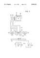
- FIG. 1is a block diagram of a control system for a printing press of the present invention
- FIG. 2is a diagrammatic view of the system of FIG. 1;
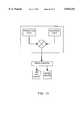
- FIG. 3is a block diagram of the control system of FIG. 1;
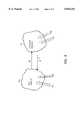
- FIG. 4is a diagrammatic view of a camera or sensor for the control system of the present invention.
- FIG. 5is a diagrammatic view of another embodiment of the camera or sensor for the control system for the present invention.
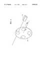
- FIG. 6is a diagrammatic view of a further embodiment of a camera or sensor for the control system of the present invention.
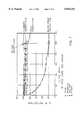
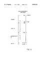
- FIG. 7is a chart plotting the normalized percentage of IR Reflection against the percentage Dot Area in a printed sheet
- FIG. 8is a diagrammatic view of a spectrum of electromagnetic waves including the visible spectrum and the infrared spectrum
- FIG. 9is a diagrammatic view of set of elements for a sensor space and ink space.
- FIG. 10is a block diagram of the sensor space and ink space in conjunction with the control system of the present invention.
- FIG. 11is a block diagram of the control system for adjusting the printing press.
- FIG. 1there is shown a control system generally designated 10 for a printing press 11 of the present invention.
- the control system 10has a 4 channel sensor 21, a data converter 23 for processing information from the sensor 21, and a device 25 for controlling ink for the press 11.
- the 4 channel sensor 21detects the energy reflected from a paper surface, such as the paper web for the press 11, in both the visible region and the infrared region of the electromagnetic spectrum.
- electromagnetic waves in the infrared regionhave a longer wave length than the visible spectrum, with the wave lengths of the electromagnetic waves in the region of visible light being approximately 400 to 700 nanometers (nm), and the wave lengths of the electromagnetic waves in the infrared region, including near infrared, being equal to or greater than 800 nm.
- the control system 10has a support 12 for placement of a sheet of paper 14 with image or indicia 16 on the sheet 14 in a configuration beneath a pair of opposed lights 18 and 20 for illuminating the sheet 14.
- the system 10has a first color video camera or sensor 22 having three channels for detecting attributes of the inks from the sheet 14 in the visible region of the electromagnetic spectrum such as red, green and blue, or cyan, magenta, and yellow, and for sending the sensed information over separate lines or leads 24, 26, and 28 to a suitable digital computer 30 or Central Processing unit having a randomly addressable memory (RAM) and a read only memory (ROM), with the computer or CPU 30 having a suitable display 32.
- RAMrandomly addressable memory
- ROMread only memory
- the system 10also has a black/white second video camera or sensor 34 having a filter 50 such that it senses the attributes of the inks in the infrared region of the electromagnetic spectrum, having a wave length greater than the wave length of the electromagnetic waves in the visible region of light.
- the camera or sensor 34thus senses infrared information from the sheet 14, and transmits the sensed information over a lead 36 to the computer 30, such that the information concerning the infrared rays is stored in and processed by the computer 30.
- the normalized percentage of infrared (IR) reflection vs. the percentage of dot areais show in the chart of FIG. 7. It will be seen that the infrared reflectance of cyan, magenta, and yellow inks show no significant change as a function of percentage of dot area. However, the normalized infrared reflectance of the black ink displays a significant change as a function of percentage of dot area, and changes from a normalized value of 100% IR reflection for 0% dot area to approximately 18% IR reflection corresponding to 100% dot area. Hence, the black ink may be easily sensed and distinguished from other color inks in the infrared region of the electromagnetic waves.
- the sheet 14may contain printed image or indicia 16 which is obtained from a current press run of the press 11, termed a production or current copy.
- a sheet 38 containing printed image or indicia 40termed a reference copy, from a previous reference press run may be placed on the support 12 beneath the cameras 22 and 34 in order to sense the energy reflected from the sheet 38, and send the sensed information to the memory of the computer 30 for storage and processing in the computer 30, as will be described below.
- the cameras or sensors 22 and 34may be used to sense both the current copy or sheet 14 and the reference copy or sheet 38.
- the information supplied by the cameras 22 and 34is formed into digital information by a suitable analog to digital converter in a frame grabber board on the computer 30.
- the computer 30operates on the digital information which is stored in its memory corresponding to the information sensed from the sheets 14 and 34 by the cameras or sensors 22 and 34.
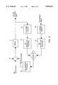
- FIG. 3there is shown a block diagram of the control system 10 for the printing press 11 of the present invention.
- the four inks (cyan, magenta, yellow, and black) of the four-color printing press 11are first preset, after which a print is made by the press 11 with a current ink setting, thus producing a production or current printed copy, as shown.
- the color and black/white video cameras or sensors 22 and 34 of FIG. 2serve as a four channel sensor 21 to capture an image of the current printed copy, and then place this information into the memory of the computer 30 after it has been formed into digital information.
- an "Ink Separation Process” 23is used to convert the red, green, blue and IR images captured by the four channel sensor 21 into four separated cyan, magenta, yellow and black ink images, which represent the amount of corresponding ink presented on the live copy.
- the "Ink Separation Precess” 23may utilize mathematic formulas, data look up tables or other suitable means to perform the data conversion task.
- the similar processesare also applied to the reference copy.
- the four channel sensor 21is used to capture the red, green, blue and IR images from the reference copy.
- the "Ink Separation Process" 23is utilized to obtain the cyan, magenta, yellow and black ink images, which represent the amount of corresponding ink presented on the reference copy.
- the ink images of the production copyare compared with the ink images of the reference copy by the computer 30 to detect the variation of ink distribution for each of the cyan, magenta, yellow and black inks.
- the determined differences in ink distributionare then processed by the computer 30 in order to obtain an indication for controlling the keys or other devices of the press 11 in an ink control process, and thus provide an indication of an ink adjustment to the press to obtain further copies which will have a closer match to the reference copy.
- the indication of ink changesmay be automatically supplied to the press 11, or the operator may utilize the indications of ink color attributes to set the press 11, such as adjustments to ink input rate by using the keys.
- the four channel sensor 21is utilized to sense not only attributes in three channels of the visible region, the fourth channel of the sensor 21 senses an attribute in the infrared region in order to determine the correct amount of inks, including black ink, to correctly reproduce the proof.
- the printing press control systemuses the four channel detector or sensor 21 to detect the energy reflected from a paper surface, such as the sheets 14 and 38, or the paper web of the press 11, with three channels being in the visible region and one channel being in the infrared region of the electromagnetic spectrum.
- the control system 10has a device 23 for converting the output of the sensing device 21 to a set of variables which represent the amount of ink presented on the paper for any of the cyan, magenta, yellow, and black inks, and a device 25 responsive to the converting device 23 for adjusting the four-color printing press 11 to maintain the color consistency.
- the bandwidth of the infrared channelmay be between 800 nm and 1100 nm, which is a portion of the near infrared region, and which is compatible with a regular silicon detector, although the working wavelength of the infrared channel may be longer than 1100 nm.
- At least three distinct channelsare utilized in the visible region which may correspond to red, green, and blue (RGB), or cyan, magenta, and yellow (CMY), or other colors.
- the bandwidth of each channel in the visible regionmay be less than 70 nm, more than 100 nm, or any value in between, with channels having a multiple peak in its passing band, such as magenta, being also included.
- the sensor device 21may be constructed from either a single element detector, a one-dimensional (linear) detector, a two-dimensional (area) detector, or other suitable detector structure, as will be seen below.
- the sensor devicemay be constructed by adding an additional infrared channel to existing devices, adding an infrared channel to a RGB color camera or a densitometer, or by extending the working band into the infrared region, e.g., adding infrared capability to a spectrophotometer.
- the light source 18 and 20 usedprovides sufficient radiated energy in both the visible region and the infrared region, depending upon the sensor working band and sensitivity.
- All possible values which are output from the sensor device 21may be used to form a vector space.
- all possible values output from the sensor device 21 with red, green, blue and infrared channelsform a four dimensional vector space R-G-B-IR, with the vector space being termed a sensor space S 1 , with each output from the sensor device 21 being termed a vector in the sensor space S 1 , with the minimum number of dimensions required by the sensor structure being 4.
- the printed image on a production or current copymay be compared with the printed image on a reference copy in the sensor space, and if the difference between the live copy L.C. s and the reference copy R.C. s is within a predefined tolerance level delta, at least for all the channels in the visible region of the sensor space, such that, L.C. s -R.C. s ! ⁇ delta, the production or current copy is said to be acceptable by definition.
- a set of variablesmay be defined to represent the amount of ink presented in a given area.
- a set of variables C, M, Y, and Kcan be defined to represent or be a function of the amount of cyan, magenta, yellow, and black ink in a given area.
- This set of variablesmay correspond to the ink volume, average ink film thickness, dot size, or other quantities related to the amount of ink in a given area on the paper surface.
- the vector space formed by this set of variablesis termed an ink space S 2 , with the ink space S 2 having a dimension of 4 for a four color printing press 11.
- a set S 2 of elements d 11 , and d 12are given, with the elements d 11 of the set S 2 being the vectors v j1 corresponding to the variables associated with the production or current copy in the ink space S 2 , and with the elements d 12 of the set S 2 being the vectors v j2 corresponding to the variables associated with the reference copy in the ink space S 2 .
- each transfer function or transformation phiwhich can map the elements d 11 and d 12 of the set S 2 or the four dimensional ink space, into the elements e 11 and e 12 of the set si or the four dimensional sensor space, with the transformation phi being termed a forward transfer function, as shown in FIGS. 9 and 10. It is noted that the subsets in each set S 1 and S 2 may overlap or may be the same.
- the forward transfer functionmay be used in a soft proof system which can generate a proof image which can be stored in the system as a reference or can be displayed on a CRT screen.
- both the production image and the reference image in the sensor space or set S 1can be mapped into the ink space or set S 2 by applying the reverse transfer function phi -1 point by point as shown in FIGS. 9 and 10.
- the difference between the production image and the reference image in the ink space S 2thus represents the difference of the ink distribution for each of the cyan, magenta, yellow, and black inks, as shown in FIG. 11.
- the difference between the live and reference images in the ink space S 2indicates which printing unit should be adjusted, which direction, up or down, it should be adjusted, and the amount of ink which should be adjusted.
- a suitable press control formulamay be developed to adjust press parameters, such as ink input rate in lithographic or letterpresses, ink consistency in flexographic or gravure presses, water input rate in lithographic presses, or temperature in any of the above, based on the differences between the production and the reference image in the ink space S 2 .
- the press adjustmentscan be achieved by the automatic control system 10, by press operator alone, or by the interaction between the automatic control system 10 and the press operator.
- the sensor device 21may be used to monitor the printing web of the press 11 directly, i.e., on press sensing, or to monitor the prints collected from the folder of the press, i.e., off press sensing. If the digital images from the color separation processing, or the film/plate images are available, the image of the reference copy in the sensor device 21 can be generated electronically by the forward transfer function phi. The electronically generated reference may be used to set up the press 11 in order to reduce the make ready time.
- the color reproduction qualitycan be maintained through the entire press run, through different press runs on different presses, or at different times.
- a closed loop automatic color reproduction control systemmay be formed without an additional color control target.
- the variation of ink, paper, and other press parameterscan be compensated such that the printed copies have the highest possible overall results in matching the reference copy.
- the camera or sensor 22may be associated with a rotating filter member 52 having filters which only transmit the desired colors F 1 , F 2 , and F 3 , such as red, green, and blue during rotation, such that the camera or sensor 22 senses and records the colors F 1 , F 2 , and F 3 , sequentially or separately from the printed material which may be taken either from the current press run or from the reference press run.
- the filter member 52may have an infrared (IR) filter F 4 in order to sense and record the energy reflected form the printed material in the infrared region.
- IRinfrared
- the camera or sensor 22may comprise a charge coupled device (CCD) with built in filters which converts light energy reflected from the printed material into electric energy in a video camera, i.e. F 1 , F 2 , F 3 , and F 4 , (IR), such as the distinct colors red, green, and blue in the visible region, and the near infrared energy in the infrared region, in order to supply the information to the computer 30 for storage and processing, as previously discussed.
- CCDcharge coupled device
- IRnear infrared energy in the infrared region
- FIG. 6Another embodiment of the camera or sensor 22 of the present invention is illustrated in FIG. 6, in which like reference numerals designate like parts.
- the camera or sensor 22has a beam splitter in order to separate the incoming light reflected from the printed material into an infrared beam for a first CCD 1, F 1 such as red for a second CCD 2, F 2 such as green for a third CCD 3, and F 3 such as blue for a fourth CCD.
- suitable prisms, lenses, or mirrorsmay be utilized to accomplish the beam splitting of light in order to obtain the desired color attributes in the various charge coupled devices to supply the information to the computer 30 for storage and processing in the computer 30, in a manner as previously described.
- any other suitable camera or sensing devicemay be utilized to obtain the desired colors.
- a control system 10 for a printing press 11which ascertains three distinct attributes, such as colors, in the visible region of electromagnetic waves and an attribute in the infrared region of the electromagnetic spectrum for the printed inks.
- the control system 10utilizes these four attributes in a four channel device to indicate and control the ink colors for use in the press 11.
- the colorsmay be sensed from a sheet taken during a current press run, and from a sheet taken during a reference press run, after which the sensed information is utilized in order to modify ink settings of a press 11 in order to obtain repeatability of the same colors from the reference run to the current press run.
- a consistent quality of colorsmay be maintained by the printing press 11 irrespective of the number of runs after the reference run has been made, and may be continuously used during a press run if desired.
- a four channel camerahaving a black/white (B/W) camera and a color camera. At least one of the cameras is equipped with a zoom to adjust the image size. Also, the cameras are provided with at least one rotational adjustment plus two additional adjustments between the two cameras.
- the two adjustmentscan be translation or rotation. This can be accomplished by mounting one of the two cameras, for example the B/W camera, on an adjustment device such as a 3-axis rotation stage. The two cameras are mounted along with the adjustment device in such manner so that both cameras point to the center of the imaging area.
- two targetsare printed using an ink containing carbon black, which can be seen in both the B/W and color cameras.
- the first targetis printed as a grid pattern, and the second is printed as an array of evenly spaced dots forming columns and rows.
- the grid patternis placed under the camera field of view.
- An imageis displayed from the B/W camera and an image from one channel of the color camera together on a monitor as separate colors.
- the red imagemight correspond to the B/W camera image, and a superimposed green image could be obtained from the red channel of the color camera.
- the zoom lensis adjusted along with the adjustment device so that these two images are aligned as close as possible on the monitor.
- the dot pattern targetis placed under the camera field of view and images are captured from the B/W and a single channel of the color camera.
- the deviceis used to find the actual X and Y positions for each dot in each of the two images.
- the average X positionis calculated for each column and then Y position of each row of dots. From these numbers the average spacing between columns and rows and the center point of the dot pattern is determined.
- the desired column and row spacingis calculated by one of the two methods:
- the desired column and row spacingequal the averaged column and row spacing so that there is no aspect ratio modification of the captured images.
- the grid coordinatesare calculated using the desired column and row spacing.
- the grid coordinatesare adjusted so that the center point of the grid is at the center point of the dot pattern. These calculated coordinates are the desired dot positions.
- transfer functionsare developed which map the actual dot positions in that image to the desired dot positions described in step 4.
- a transfer functionis developed for each group of four dots forming a rectangular shape.
- An example of such a transfer functionsis a bi-linear transfer function.
- the transfer function developed for a single channel of the color camerais also applicable to the two remaining color images.
- an imageis captured under the camera setup described in step 2.
- a geometric transfer operationis performed for each of the four images based on the individual transfer functions developed for that image.
- steps 4-6introduce a way to translate the four images from the two cameras so that the geometric distortion can be corrected.
- the aspect ratiocan also be corrected if the step of 4b is used.
- the geometric distortionis tolerable in at least one camera image
- the number of images to be translatedcan be reduced. This can be accomplished by using the camera without distortion as a reference and translating only the image or images from the other camera. For example, if the color camera is selected to be the reference, only the B/W camera would have to be translated. In this case, the actual dot positions obtained from the single channel from the color camera would be used as the desired dot positions to develop the transfer functions.
Landscapes
- Engineering & Computer Science (AREA)
- Quality & Reliability (AREA)
- Inking, Control Or Cleaning Of Printing Machines (AREA)
Abstract
Description
Claims (6)
Priority Applications (1)
| Application Number | Priority Date | Filing Date | Title |
|---|---|---|---|
| US08/911,214US5816151A (en) | 1995-09-29 | 1997-08-14 | Device for alignment of images in a control system for a printing press |
Applications Claiming Priority (2)
| Application Number | Priority Date | Filing Date | Title |
|---|---|---|---|
| US53704595A | 1995-09-29 | 1995-09-29 | |
| US08/911,214US5816151A (en) | 1995-09-29 | 1997-08-14 | Device for alignment of images in a control system for a printing press |
Related Parent Applications (1)
| Application Number | Title | Priority Date | Filing Date |
|---|---|---|---|
| US53704595AContinuation | 1995-09-29 | 1995-09-29 |
Publications (1)
| Publication Number | Publication Date |
|---|---|
| US5816151Atrue US5816151A (en) | 1998-10-06 |
Family
ID=24140950
Family Applications (1)
| Application Number | Title | Priority Date | Filing Date |
|---|---|---|---|
| US08/911,214Expired - LifetimeUS5816151A (en) | 1995-09-29 | 1997-08-14 | Device for alignment of images in a control system for a printing press |
Country Status (3)
| Country | Link |
|---|---|
| US (1) | US5816151A (en) |
| EP (1) | EP0765748A3 (en) |
| JP (1) | JPH09216346A (en) |
Cited By (18)
| Publication number | Priority date | Publication date | Assignee | Title |
|---|---|---|---|---|
| US5964149A (en)* | 1997-08-20 | 1999-10-12 | Bristol-Myers Squibb Co. | Cylinder color printing method and product using improved misregistration detection |
| US5983792A (en)* | 1997-06-06 | 1999-11-16 | Komori Corporation | Device for detecting matters printed with infrared ray reflective and absorptive ink |
| US6330001B1 (en)* | 1997-09-10 | 2001-12-11 | Nec Corporation | Device and computer-readable record medium for image position adjustment |
| US20030058462A1 (en)* | 2001-03-02 | 2003-03-27 | The Ackley Martinez Company Dba Mgi Studio | Printing adjustment system and method |
| US20030093805A1 (en)* | 2001-11-15 | 2003-05-15 | Gin J.M. Jack | Dual camera surveillance and control system |
| US20030147101A1 (en)* | 2002-02-06 | 2003-08-07 | Quad/Tech, Inc. | Camera assembly for a printing press |
| US20030156299A1 (en)* | 2001-07-30 | 2003-08-21 | The Ackley Martinz Company Dba Mgi Studio | Color management processing system |
| US20030222230A1 (en)* | 2002-04-09 | 2003-12-04 | Ralf Brauner | Method and apparatus for the capture of scanning positions in printed images |
| EP1384580A1 (en)* | 2002-07-27 | 2004-01-28 | serv-o-tec Druck- und Papierverarbeitungsmaschinen GmbH | Method and device for setting registers of a printing press |
| US6705219B2 (en)* | 2001-09-06 | 2004-03-16 | Heidelberger Druckmaschinen Ag | Rotary offset printing unit with rubber blanket belt and offset printing method |
| US6725772B2 (en) | 2001-07-30 | 2004-04-27 | Ackley Martinez Company | System admixture compensation system and method |
| US7013803B2 (en) | 2002-02-06 | 2006-03-21 | Quad/Tech, Inc. | Color registration control system for a printing press |
| US20070157831A1 (en)* | 2004-01-28 | 2007-07-12 | Eckert Gunther O | Methods for the compensation of a transverse elongation and/or longitudinal elongation of a printing material and printing press with several printing couples generating at least one printed image on a printing material |
| US20080216689A1 (en)* | 2004-04-22 | 2008-09-11 | Matthias Riepenhoff | Device and Method for Recognition of Register Errors |
| US20090025583A1 (en)* | 2007-06-28 | 2009-01-29 | Goss International Americas Inc. | Variable cutoff printing unit with belt blanket and method of printing |
| US20090064881A1 (en)* | 2007-06-28 | 2009-03-12 | Goss International Americas, Inc. | Variable cutoff printing unit and method of printing |
| US7605959B2 (en) | 2005-01-05 | 2009-10-20 | The Ackley Martinez Company | System and method of color image transformation |
| US20100072936A1 (en)* | 2008-09-25 | 2010-03-25 | Goss International Americas, Inc. | Simultaneous zero verification for motors in a printing press |
Citations (60)
| Publication number | Priority date | Publication date | Assignee | Title |
|---|---|---|---|---|
| US2968988A (en)* | 1955-03-18 | 1961-01-24 | Crosfield J F Ltd | Apparatus for indicating changes in ink |
| US3612753A (en)* | 1969-04-23 | 1971-10-12 | Ventures Res & Dev | Self-adaptive system for the reproduction of color |
| US3806633A (en)* | 1972-01-18 | 1974-04-23 | Westinghouse Electric Corp | Multispectral data sensor and display system |
| US4084183A (en)* | 1970-03-18 | 1978-04-11 | Dr. Ing. Rudolf Hell Gmbh. | Method for the electro-optical reproduction of half-tone pictures |
| US4249217A (en)* | 1979-05-29 | 1981-02-03 | International Business Machines Corporation | Separated sensor array abutment |
| US4308533A (en)* | 1978-10-27 | 1981-12-29 | Bbc Brown, Boveri & Company, Ltd. | Display element having improved spacing and through-connecting of plane-parallel electrode plates, and method of making |
| US4481532A (en)* | 1982-06-28 | 1984-11-06 | R. R. Donnelley & Sons Company | Method of determining and storing color printing information |
| EP0127831A2 (en)* | 1983-06-02 | 1984-12-12 | Web Printing Controls Co. | Closed loop register control |
| US4543613A (en)* | 1982-10-28 | 1985-09-24 | Dainippon Screen Seizo Kabushiki Kaisha | Method for producing halftone dots in a halftone plate recording apparatus |
| US4649500A (en)* | 1984-10-26 | 1987-03-10 | Dainippon Screen Mfg. Co., Ltd. | Collection method of data on feed amount of printing ink and system therefor |
| US4667227A (en)* | 1984-04-23 | 1987-05-19 | Canon Kabushiki Kaisha | Color image reading apparatus |
| US4680625A (en)* | 1984-07-18 | 1987-07-14 | Konishiroku Photo Industry Co., Ltd. | Method and apparatus for multicolor image forming |
| US4713684A (en)* | 1983-03-08 | 1987-12-15 | Canon Kabushiki Kaisha | Image processing apparatus for discriminating and processing different formats of color image signals |
| EP0142470B1 (en)* | 1983-11-04 | 1988-01-07 | GRETAG Aktiengesellschaft | Method and device for judging the printing quality of a printed object, preferably printed by an offset printing machine, and offset printing machine provided with such a device |
| US4752822A (en)* | 1983-03-08 | 1988-06-21 | Canon Kabushiki Kaisha | Color halftone image processing apparatus producing various screen angles and having an adaptive color image data conversion look-up table and a small-capacity masking memory |
| US4758885A (en)* | 1985-06-17 | 1988-07-19 | Canon Kabushiki Kaisha | Method of processing color image |
| US4790022A (en)* | 1985-03-06 | 1988-12-06 | Lockwood Graders (Uk) Limited | Method and apparatus for detecting colored regions, and method and apparatus for articles thereby |
| US4879594A (en)* | 1987-09-23 | 1989-11-07 | Crosfield Electronics Limited | Reproduction of colored images |
| US4908712A (en)* | 1988-03-09 | 1990-03-13 | Minolta Camera Kabushiki Kaisha | Method for tone reproduction in image forming system |
| US4910593A (en)* | 1989-04-14 | 1990-03-20 | Entech Engineering, Inc. | System for geological defect detection utilizing composite video-infrared thermography |
| US4926254A (en)* | 1987-09-22 | 1990-05-15 | Dainippon Screen Mfg. Co., Ltd. | Method of correcting color image data for obtaining proof image |
| US4967379A (en)* | 1987-12-16 | 1990-10-30 | Gretag Aktiengesellschaft | Process for the ink control or regulation of a printing machine by comparing desired color to obtainable color data |
| US4967264A (en)* | 1989-05-30 | 1990-10-30 | Eastman Kodak Company | Color sequential optical offset image sampling system |
| US4975862A (en)* | 1988-01-14 | 1990-12-04 | Gretag Aktiengesellschaft | Process and apparatus for the ink control of a printing machine |
| US4985930A (en)* | 1987-09-24 | 1991-01-15 | Hitachi, Ltd. | Image data filing system and image data correcting method |
| US5029107A (en)* | 1989-03-31 | 1991-07-02 | International Business Corporation | Apparatus and accompanying method for converting a bit mapped monochromatic image to a grey scale image using table look up operations |
| US5045937A (en)* | 1989-08-25 | 1991-09-03 | Space Island Products & Services, Inc. | Geographical surveying using multiple cameras to obtain split-screen images with overlaid geographical coordinates |
| US5105466A (en)* | 1986-09-26 | 1992-04-14 | Olympus Optical Co., Ltd. | Method and apparatus for detecting corresponding regions between picture images |
| US5125037A (en)* | 1987-08-31 | 1992-06-23 | Valtion Teknillinen Tutkimuskeskus | Procedure for monitoring printing quality |
| US5138677A (en)* | 1991-07-08 | 1992-08-11 | General Dynamics Corporation, Electronics Division | Broadband optical power summer |
| US5163012A (en)* | 1989-07-24 | 1992-11-10 | Man Roland Druckmaschinen Ag | Apparatus for carrying out the comprehensive quality control of printed sheets |
| US5166789A (en)* | 1989-08-25 | 1992-11-24 | Space Island Products & Services, Inc. | Geographical surveying using cameras in combination with flight computers to obtain images with overlaid geographical coordinates |
| US5175772A (en)* | 1991-01-02 | 1992-12-29 | Motorola, Inc. | Automated test for displays using display patterns |
| US5216504A (en)* | 1991-09-25 | 1993-06-01 | Display Laboratories, Inc. | Automatic precision video monitor alignment system |
| US5215011A (en)* | 1991-05-06 | 1993-06-01 | Bobst Sa | Device for scanning pale color marks on a printing machine |
| US5271066A (en)* | 1990-04-26 | 1993-12-14 | Agfa-Gevaert, N.V. | Coordinate determining device |
| US5282064A (en)* | 1989-08-31 | 1994-01-25 | Canon Kabushiki Kaisha | Apparatus for simultaneous reading of reflective and light conductive portions of an original |
| US5302833A (en)* | 1989-10-26 | 1994-04-12 | Hamar Laser Instrument, Inc. | Rotational orientation sensor for laser alignment control system |
| EP0598490A1 (en)* | 1992-10-28 | 1994-05-25 | Quad/Tech, Inc. | Colour registration system for a printing press |
| EP0601259A1 (en)* | 1992-12-09 | 1994-06-15 | GRETAG Aktiengesellschaft | Method and device to determine the required quantity of printing ink for one image in offset printing |
| US5359677A (en)* | 1990-12-11 | 1994-10-25 | Sharp Kabushiki Kaisha | Image reader and facsimile machine using such image reader |
| DE4321177A1 (en)* | 1993-06-25 | 1995-01-05 | Heidelberger Druckmasch Ag | Device for parallel image inspection and color control on a printed product |
| US5383036A (en)* | 1993-09-29 | 1995-01-17 | Xerox Corporation | Enhancement of multiple color images without color separation error by inverse symmetrical template matching |
| US5384621A (en)* | 1994-01-04 | 1995-01-24 | Xerox Corporation | Document detection apparatus |
| US5394183A (en)* | 1992-05-05 | 1995-02-28 | Milliken Research Corporation | Method and apparatus for entering coordinates into a computer |
| US5404156A (en)* | 1992-07-25 | 1995-04-04 | Fuji Xerox Co., Ltd. | Method and apparatus for forming a full-color image |
| US5404158A (en)* | 1992-11-12 | 1995-04-04 | Xerox Corporation | Ink jet printer maintenance system |
| US5422739A (en)* | 1991-07-08 | 1995-06-06 | Canon Kabushiki Kaisha | Color expressing method, color image reading apparatus and color image processing apparatus |
| US5424553A (en)* | 1994-05-16 | 1995-06-13 | Eastman Kodak Company | Method for aligning a lenticular material for printing |
| US5444799A (en)* | 1992-03-26 | 1995-08-22 | Sanyo Electric Co., Ltd. | Image processing apparatus and method of strain correction in such an image processing apparatus |
| US5465163A (en)* | 1991-03-18 | 1995-11-07 | Canon Kabushiki Kaisha | Image processing method and apparatus for processing oversized original images and for synthesizing multiple images |
| US5471324A (en)* | 1994-04-05 | 1995-11-28 | Xerox Corporation | Color printer calibration with improved color mapping linearity |
| US5473733A (en)* | 1992-03-25 | 1995-12-05 | Scitex Corporation Ltd. | Technique for generating image reproduction |
| US5508810A (en)* | 1991-10-17 | 1996-04-16 | Ricoh Company, Ltd. | Image recorder for properly orienting output images |
| US5509115A (en)* | 1990-08-08 | 1996-04-16 | Peerless Systems Corporation | Method and apparatus for displaying a page with graphics information on a continuous synchronous raster output device |
| US5521722A (en)* | 1990-01-31 | 1996-05-28 | Thomas De La Rue Limited | Image handling facilitating computer aided design and manufacture of documents |
| US5526143A (en)* | 1992-09-16 | 1996-06-11 | Scitex Corporation Ltd. | Apparatus and technique for generating a screened reproduction of an image |
| US5528387A (en)* | 1994-11-23 | 1996-06-18 | Xerox Corporation | Electronic image registration for a scanner |
| US5533144A (en)* | 1994-10-17 | 1996-07-02 | Xerox Corporation | Anti-counterfeit pattern detector and method |
| US5542002A (en)* | 1993-06-11 | 1996-07-30 | Western Litho Plate & Supply Co. | Method and apparatus for automatically inspecting a lithographic plate and reading its folio |
- 1996
- 1996-09-25EPEP96115365Apatent/EP0765748A3/ennot_activeWithdrawn
- 1996-09-30JPJP8293099Apatent/JPH09216346A/enactivePending
- 1997
- 1997-08-14USUS08/911,214patent/US5816151A/ennot_activeExpired - Lifetime
Patent Citations (61)
| Publication number | Priority date | Publication date | Assignee | Title |
|---|---|---|---|---|
| US2968988A (en)* | 1955-03-18 | 1961-01-24 | Crosfield J F Ltd | Apparatus for indicating changes in ink |
| US3612753A (en)* | 1969-04-23 | 1971-10-12 | Ventures Res & Dev | Self-adaptive system for the reproduction of color |
| US4084183A (en)* | 1970-03-18 | 1978-04-11 | Dr. Ing. Rudolf Hell Gmbh. | Method for the electro-optical reproduction of half-tone pictures |
| US3806633A (en)* | 1972-01-18 | 1974-04-23 | Westinghouse Electric Corp | Multispectral data sensor and display system |
| US4308533A (en)* | 1978-10-27 | 1981-12-29 | Bbc Brown, Boveri & Company, Ltd. | Display element having improved spacing and through-connecting of plane-parallel electrode plates, and method of making |
| US4249217A (en)* | 1979-05-29 | 1981-02-03 | International Business Machines Corporation | Separated sensor array abutment |
| US4481532A (en)* | 1982-06-28 | 1984-11-06 | R. R. Donnelley & Sons Company | Method of determining and storing color printing information |
| US4543613A (en)* | 1982-10-28 | 1985-09-24 | Dainippon Screen Seizo Kabushiki Kaisha | Method for producing halftone dots in a halftone plate recording apparatus |
| US4713684A (en)* | 1983-03-08 | 1987-12-15 | Canon Kabushiki Kaisha | Image processing apparatus for discriminating and processing different formats of color image signals |
| US4752822A (en)* | 1983-03-08 | 1988-06-21 | Canon Kabushiki Kaisha | Color halftone image processing apparatus producing various screen angles and having an adaptive color image data conversion look-up table and a small-capacity masking memory |
| EP0127831A2 (en)* | 1983-06-02 | 1984-12-12 | Web Printing Controls Co. | Closed loop register control |
| EP0142470B1 (en)* | 1983-11-04 | 1988-01-07 | GRETAG Aktiengesellschaft | Method and device for judging the printing quality of a printed object, preferably printed by an offset printing machine, and offset printing machine provided with such a device |
| US4667227A (en)* | 1984-04-23 | 1987-05-19 | Canon Kabushiki Kaisha | Color image reading apparatus |
| US4680625A (en)* | 1984-07-18 | 1987-07-14 | Konishiroku Photo Industry Co., Ltd. | Method and apparatus for multicolor image forming |
| US4649500A (en)* | 1984-10-26 | 1987-03-10 | Dainippon Screen Mfg. Co., Ltd. | Collection method of data on feed amount of printing ink and system therefor |
| US4790022A (en)* | 1985-03-06 | 1988-12-06 | Lockwood Graders (Uk) Limited | Method and apparatus for detecting colored regions, and method and apparatus for articles thereby |
| US4758885A (en)* | 1985-06-17 | 1988-07-19 | Canon Kabushiki Kaisha | Method of processing color image |
| US5105466A (en)* | 1986-09-26 | 1992-04-14 | Olympus Optical Co., Ltd. | Method and apparatus for detecting corresponding regions between picture images |
| US5125037A (en)* | 1987-08-31 | 1992-06-23 | Valtion Teknillinen Tutkimuskeskus | Procedure for monitoring printing quality |
| US4926254A (en)* | 1987-09-22 | 1990-05-15 | Dainippon Screen Mfg. Co., Ltd. | Method of correcting color image data for obtaining proof image |
| US4879594A (en)* | 1987-09-23 | 1989-11-07 | Crosfield Electronics Limited | Reproduction of colored images |
| US4985930A (en)* | 1987-09-24 | 1991-01-15 | Hitachi, Ltd. | Image data filing system and image data correcting method |
| US4967379A (en)* | 1987-12-16 | 1990-10-30 | Gretag Aktiengesellschaft | Process for the ink control or regulation of a printing machine by comparing desired color to obtainable color data |
| US4975862A (en)* | 1988-01-14 | 1990-12-04 | Gretag Aktiengesellschaft | Process and apparatus for the ink control of a printing machine |
| US4908712A (en)* | 1988-03-09 | 1990-03-13 | Minolta Camera Kabushiki Kaisha | Method for tone reproduction in image forming system |
| US5029107A (en)* | 1989-03-31 | 1991-07-02 | International Business Corporation | Apparatus and accompanying method for converting a bit mapped monochromatic image to a grey scale image using table look up operations |
| US4910593A (en)* | 1989-04-14 | 1990-03-20 | Entech Engineering, Inc. | System for geological defect detection utilizing composite video-infrared thermography |
| US4967264A (en)* | 1989-05-30 | 1990-10-30 | Eastman Kodak Company | Color sequential optical offset image sampling system |
| US5163012A (en)* | 1989-07-24 | 1992-11-10 | Man Roland Druckmaschinen Ag | Apparatus for carrying out the comprehensive quality control of printed sheets |
| US5166789A (en)* | 1989-08-25 | 1992-11-24 | Space Island Products & Services, Inc. | Geographical surveying using cameras in combination with flight computers to obtain images with overlaid geographical coordinates |
| US5045937A (en)* | 1989-08-25 | 1991-09-03 | Space Island Products & Services, Inc. | Geographical surveying using multiple cameras to obtain split-screen images with overlaid geographical coordinates |
| US5282064A (en)* | 1989-08-31 | 1994-01-25 | Canon Kabushiki Kaisha | Apparatus for simultaneous reading of reflective and light conductive portions of an original |
| US5302833A (en)* | 1989-10-26 | 1994-04-12 | Hamar Laser Instrument, Inc. | Rotational orientation sensor for laser alignment control system |
| US5521722A (en)* | 1990-01-31 | 1996-05-28 | Thomas De La Rue Limited | Image handling facilitating computer aided design and manufacture of documents |
| US5271066A (en)* | 1990-04-26 | 1993-12-14 | Agfa-Gevaert, N.V. | Coordinate determining device |
| US5509115A (en)* | 1990-08-08 | 1996-04-16 | Peerless Systems Corporation | Method and apparatus for displaying a page with graphics information on a continuous synchronous raster output device |
| US5359677A (en)* | 1990-12-11 | 1994-10-25 | Sharp Kabushiki Kaisha | Image reader and facsimile machine using such image reader |
| US5175772A (en)* | 1991-01-02 | 1992-12-29 | Motorola, Inc. | Automated test for displays using display patterns |
| US5465163A (en)* | 1991-03-18 | 1995-11-07 | Canon Kabushiki Kaisha | Image processing method and apparatus for processing oversized original images and for synthesizing multiple images |
| US5215011A (en)* | 1991-05-06 | 1993-06-01 | Bobst Sa | Device for scanning pale color marks on a printing machine |
| US5422739A (en)* | 1991-07-08 | 1995-06-06 | Canon Kabushiki Kaisha | Color expressing method, color image reading apparatus and color image processing apparatus |
| US5138677A (en)* | 1991-07-08 | 1992-08-11 | General Dynamics Corporation, Electronics Division | Broadband optical power summer |
| US5216504A (en)* | 1991-09-25 | 1993-06-01 | Display Laboratories, Inc. | Automatic precision video monitor alignment system |
| US5508810A (en)* | 1991-10-17 | 1996-04-16 | Ricoh Company, Ltd. | Image recorder for properly orienting output images |
| US5473733A (en)* | 1992-03-25 | 1995-12-05 | Scitex Corporation Ltd. | Technique for generating image reproduction |
| US5444799A (en)* | 1992-03-26 | 1995-08-22 | Sanyo Electric Co., Ltd. | Image processing apparatus and method of strain correction in such an image processing apparatus |
| US5394183A (en)* | 1992-05-05 | 1995-02-28 | Milliken Research Corporation | Method and apparatus for entering coordinates into a computer |
| US5404156A (en)* | 1992-07-25 | 1995-04-04 | Fuji Xerox Co., Ltd. | Method and apparatus for forming a full-color image |
| US5526143A (en)* | 1992-09-16 | 1996-06-11 | Scitex Corporation Ltd. | Apparatus and technique for generating a screened reproduction of an image |
| EP0598490A1 (en)* | 1992-10-28 | 1994-05-25 | Quad/Tech, Inc. | Colour registration system for a printing press |
| US5412577A (en)* | 1992-10-28 | 1995-05-02 | Quad/Tech International | Color registration system for a printing press |
| US5404158A (en)* | 1992-11-12 | 1995-04-04 | Xerox Corporation | Ink jet printer maintenance system |
| EP0601259A1 (en)* | 1992-12-09 | 1994-06-15 | GRETAG Aktiengesellschaft | Method and device to determine the required quantity of printing ink for one image in offset printing |
| US5542002A (en)* | 1993-06-11 | 1996-07-30 | Western Litho Plate & Supply Co. | Method and apparatus for automatically inspecting a lithographic plate and reading its folio |
| DE4321177A1 (en)* | 1993-06-25 | 1995-01-05 | Heidelberger Druckmasch Ag | Device for parallel image inspection and color control on a printed product |
| US5383036A (en)* | 1993-09-29 | 1995-01-17 | Xerox Corporation | Enhancement of multiple color images without color separation error by inverse symmetrical template matching |
| US5384621A (en)* | 1994-01-04 | 1995-01-24 | Xerox Corporation | Document detection apparatus |
| US5471324A (en)* | 1994-04-05 | 1995-11-28 | Xerox Corporation | Color printer calibration with improved color mapping linearity |
| US5424553A (en)* | 1994-05-16 | 1995-06-13 | Eastman Kodak Company | Method for aligning a lenticular material for printing |
| US5533144A (en)* | 1994-10-17 | 1996-07-02 | Xerox Corporation | Anti-counterfeit pattern detector and method |
| US5528387A (en)* | 1994-11-23 | 1996-06-18 | Xerox Corporation | Electronic image registration for a scanner |
Non-Patent Citations (1)
| Title |
|---|
| European Search Report issued in European Patent Application No. 96 11 5365, dated Jun. 3, 1997.* |
Cited By (24)
| Publication number | Priority date | Publication date | Assignee | Title |
|---|---|---|---|---|
| US5983792A (en)* | 1997-06-06 | 1999-11-16 | Komori Corporation | Device for detecting matters printed with infrared ray reflective and absorptive ink |
| US5964149A (en)* | 1997-08-20 | 1999-10-12 | Bristol-Myers Squibb Co. | Cylinder color printing method and product using improved misregistration detection |
| US6330001B1 (en)* | 1997-09-10 | 2001-12-11 | Nec Corporation | Device and computer-readable record medium for image position adjustment |
| US20030058462A1 (en)* | 2001-03-02 | 2003-03-27 | The Ackley Martinez Company Dba Mgi Studio | Printing adjustment system and method |
| US7148995B2 (en) | 2001-03-02 | 2006-12-12 | The Ackley Martinez Company | Printing adjustment system and method |
| US20030156299A1 (en)* | 2001-07-30 | 2003-08-21 | The Ackley Martinz Company Dba Mgi Studio | Color management processing system |
| US6725772B2 (en) | 2001-07-30 | 2004-04-27 | Ackley Martinez Company | System admixture compensation system and method |
| US6705219B2 (en)* | 2001-09-06 | 2004-03-16 | Heidelberger Druckmaschinen Ag | Rotary offset printing unit with rubber blanket belt and offset printing method |
| US20030093805A1 (en)* | 2001-11-15 | 2003-05-15 | Gin J.M. Jack | Dual camera surveillance and control system |
| US7253929B2 (en) | 2002-02-06 | 2007-08-07 | Quad/Tech, Inc. | Camera assembly for a printing press |
| US20030147101A1 (en)* | 2002-02-06 | 2003-08-07 | Quad/Tech, Inc. | Camera assembly for a printing press |
| US7013803B2 (en) | 2002-02-06 | 2006-03-21 | Quad/Tech, Inc. | Color registration control system for a printing press |
| US20030222230A1 (en)* | 2002-04-09 | 2003-12-04 | Ralf Brauner | Method and apparatus for the capture of scanning positions in printed images |
| EP1384580A1 (en)* | 2002-07-27 | 2004-01-28 | serv-o-tec Druck- und Papierverarbeitungsmaschinen GmbH | Method and device for setting registers of a printing press |
| US7614343B2 (en)* | 2004-01-28 | 2009-11-10 | Koenig & Bauer Aktiengesellschaft | Methods for the compensation of a transverse elongation and/or longitudinal elongation of a printing material and printing press with several printing couples generating at least one printed image on a printing material |
| US20070157831A1 (en)* | 2004-01-28 | 2007-07-12 | Eckert Gunther O | Methods for the compensation of a transverse elongation and/or longitudinal elongation of a printing material and printing press with several printing couples generating at least one printed image on a printing material |
| US20080216689A1 (en)* | 2004-04-22 | 2008-09-11 | Matthias Riepenhoff | Device and Method for Recognition of Register Errors |
| US7605959B2 (en) | 2005-01-05 | 2009-10-20 | The Ackley Martinez Company | System and method of color image transformation |
| US20090025583A1 (en)* | 2007-06-28 | 2009-01-29 | Goss International Americas Inc. | Variable cutoff printing unit with belt blanket and method of printing |
| US20090064881A1 (en)* | 2007-06-28 | 2009-03-12 | Goss International Americas, Inc. | Variable cutoff printing unit and method of printing |
| US8141489B2 (en) | 2007-06-28 | 2012-03-27 | Goss International Americas, Inc. | Variable cutoff printing unit and method of printing |
| US8161874B2 (en) | 2007-06-28 | 2012-04-24 | Goss International Americas, Inc. | Variable cutoff printing unit with belt blanket and method of printing |
| US20100072936A1 (en)* | 2008-09-25 | 2010-03-25 | Goss International Americas, Inc. | Simultaneous zero verification for motors in a printing press |
| US8102136B2 (en)* | 2008-09-25 | 2012-01-24 | Goss International Americas, Inc. | Simultaneous zero verification for motors in a printing press |
Also Published As
| Publication number | Publication date |
|---|---|
| EP0765748A2 (en) | 1997-04-02 |
| EP0765748A3 (en) | 1997-08-13 |
| JPH09216346A (en) | 1997-08-19 |
Similar Documents
| Publication | Publication Date | Title |
|---|---|---|
| US5812705A (en) | Device for automatically aligning a production copy image with a reference copy image in a printing press control system | |
| US5903712A (en) | Ink separation device for printing press ink feed control | |
| JP4055866B2 (en) | Video-based color detection device for printing press control systems | |
| US5816151A (en) | Device for alignment of images in a control system for a printing press | |
| US5841955A (en) | Control system for a printing press | |
| CA1089771A (en) | Apparatus for producing corrected color chromatic components | |
| US5805280A (en) | Control system for a printing press | |
| JPH06278274A (en) | Color registering device for press | |
| EP0860277B1 (en) | A system and method for registration control on-press during press set-up and printing | |
| WO2006083702A2 (en) | Color control of a web printing press utilizing intra-image color measurements | |
| US20020026879A1 (en) | System and method for registration control on-press during press set-up and printing | |
| JP2001501782A (en) | Method and system for automatically monitoring the color of an object in a vision station | |
| EP0658428B1 (en) | Control system for a printing press | |
| US6885394B1 (en) | Method and apparatus for outputting multi-band image | |
| CN101155692A (en) | Color control of a web printing press using intra-image color measurements | |
| EP1433605A1 (en) | Method and apparatus for controlling the Ink feeding rate | |
| EP0703700B1 (en) | Method of and apparatus for predicting image | |
| EP0795400A1 (en) | Device for automatically aligning a production copy image with a reference copy image in a printing press control system | |
| JP3209053B2 (en) | Color reproduction device | |
| JPH07205410A (en) | Control system for press | |
| JPH09254456A (en) | Image matching device for printer control system | |
| JPH04503258A (en) | Film making device for copy image printing | |
| GB1566263A (en) | Measuring optical characteristic | |
| EP0357177B1 (en) | Method and apparatus for color separation scanning |
Legal Events
| Date | Code | Title | Description |
|---|---|---|---|
| STCF | Information on status: patent grant | Free format text:PATENTED CASE | |
| FEPP | Fee payment procedure | Free format text:PAYOR NUMBER ASSIGNED (ORIGINAL EVENT CODE: ASPN); ENTITY STATUS OF PATENT OWNER: LARGE ENTITY | |
| FPAY | Fee payment | Year of fee payment:4 | |
| REMI | Maintenance fee reminder mailed | ||
| AS | Assignment | Owner name:U.S. BANK, N.A., AS COLLATERAL AGENT, MINNESOTA Free format text:SECURITY AGREEMENT;ASSIGNOR:GOSS INTERNATIONAL CORPORATION;REEL/FRAME:013913/0573 Effective date:20030228 | |
| AS | Assignment | Owner name:GOSS INTERNATIONAL CORPORATION, ILLINOIS Free format text:ASSIGNMENT OF ASSIGNORS INTEREST;ASSIGNOR:GOSS GRAPHIC SYSTEMS, INC.;REEL/FRAME:013897/0864 Effective date:20030325 | |
| AS | Assignment | Owner name:U.S. BANK, N.A., MINNESOTA Free format text:SECURITY AGREEMENT;ASSIGNOR:GOSS INTERNATIONAL CORPORATION;REEL/FRAME:015748/0855 Effective date:20040806 Owner name:U.S. BANK, N.A.,MINNESOTA Free format text:SECURITY AGREEMENT;ASSIGNOR:GOSS INTERNATIONAL CORPORATION;REEL/FRAME:015748/0855 Effective date:20040806 | |
| FPAY | Fee payment | Year of fee payment:8 | |
| AS | Assignment | Owner name:U.S. BANK NATIONAL ASSOCIATION, AS COLLATERAL AGEN Free format text:SECURITY AGREEMENT;ASSIGNOR:GOSS INTERNATIONAL CORPORATION;REEL/FRAME:022960/0132 Effective date:20090710 | |
| FPAY | Fee payment | Year of fee payment:12 | |
| AS | Assignment | Owner name:GOSS INTERNATIONAL CORPORATION,ILLINOIS Free format text:RELEASE OF SECURITY INTEREST (GRANTED IN REEL 015748; FRAME: 0855);ASSIGNOR:U.S. BANK, N.A., AS COLLATERAL AGENT;REEL/FRAME:024563/0176 Effective date:20100611 Owner name:GOSS INTERNATIONAL CORPORATION,ILLINOIS Free format text:RELEASE OF SECURITY INTEREST (GRANTED IN REEL 013913; FRAME: 0573);ASSIGNOR:U.S. BANK, N.A., AS COLLATERAL AGENT;REEL/FRAME:024563/0188 Effective date:20100611 | |
| AS | Assignment | Owner name:GOSS INTERNATIONAL CORPORATION, ILLINOIS Free format text:RELEASE OF SECURITY INTEREST (GRANTED IN REEL 022960; FRAME 0132);ASSIGNOR:U.S. BANK, N.A., AS COLLATERAL AGENT;REEL/FRAME:025008/0324 Effective date:20100914 | |
| AS | Assignment | Owner name:SHANGHAI ELECTRIC (GROUP) CORPORATION, CHINA Free format text:ASSIGNMENT OF ASSIGNORS INTEREST;ASSIGNOR:GOSS INTERNATIONAL CORPORATION;REEL/FRAME:048304/0460 Effective date:20101231 |