US5815904A - Method for making a stent - Google Patents
Method for making a stentDownload PDFInfo
- Publication number
- US5815904A US5815904AUS08/816,666US81666697AUS5815904AUS 5815904 AUS5815904 AUS 5815904AUS 81666697 AUS81666697 AUS 81666697AUS 5815904 AUS5815904 AUS 5815904A
- Authority
- US
- United States
- Prior art keywords
- pieces
- stent
- elongated structure
- radial
- cross
- Prior art date
- Legal status (The legal status is an assumption and is not a legal conclusion. Google has not performed a legal analysis and makes no representation as to the accuracy of the status listed.)
- Expired - Lifetime
Links
Images


Classifications
- A—HUMAN NECESSITIES
- A61—MEDICAL OR VETERINARY SCIENCE; HYGIENE
- A61F—FILTERS IMPLANTABLE INTO BLOOD VESSELS; PROSTHESES; DEVICES PROVIDING PATENCY TO, OR PREVENTING COLLAPSING OF, TUBULAR STRUCTURES OF THE BODY, e.g. STENTS; ORTHOPAEDIC, NURSING OR CONTRACEPTIVE DEVICES; FOMENTATION; TREATMENT OR PROTECTION OF EYES OR EARS; BANDAGES, DRESSINGS OR ABSORBENT PADS; FIRST-AID KITS
- A61F2/00—Filters implantable into blood vessels; Prostheses, i.e. artificial substitutes or replacements for parts of the body; Appliances for connecting them with the body; Devices providing patency to, or preventing collapsing of, tubular structures of the body, e.g. stents
- A61F2/82—Devices providing patency to, or preventing collapsing of, tubular structures of the body, e.g. stents
- A61F2/86—Stents in a form characterised by the wire-like elements; Stents in the form characterised by a net-like or mesh-like structure
- A61F2/90—Stents in a form characterised by the wire-like elements; Stents in the form characterised by a net-like or mesh-like structure characterised by a net-like or mesh-like structure
- A61F2/91—Stents in a form characterised by the wire-like elements; Stents in the form characterised by a net-like or mesh-like structure characterised by a net-like or mesh-like structure made from perforated sheets or tubes, e.g. perforated by laser cuts or etched holes
- A61F2/915—Stents in a form characterised by the wire-like elements; Stents in the form characterised by a net-like or mesh-like structure characterised by a net-like or mesh-like structure made from perforated sheets or tubes, e.g. perforated by laser cuts or etched holes with bands having a meander structure, adjacent bands being connected to each other
- A61F2002/91533—Stents in a form characterised by the wire-like elements; Stents in the form characterised by a net-like or mesh-like structure characterised by a net-like or mesh-like structure made from perforated sheets or tubes, e.g. perforated by laser cuts or etched holes with bands having a meander structure, adjacent bands being connected to each other characterised by the phase between adjacent bands
- A61F2002/91541—Adjacent bands are arranged out of phase
- A—HUMAN NECESSITIES
- A61—MEDICAL OR VETERINARY SCIENCE; HYGIENE
- A61F—FILTERS IMPLANTABLE INTO BLOOD VESSELS; PROSTHESES; DEVICES PROVIDING PATENCY TO, OR PREVENTING COLLAPSING OF, TUBULAR STRUCTURES OF THE BODY, e.g. STENTS; ORTHOPAEDIC, NURSING OR CONTRACEPTIVE DEVICES; FOMENTATION; TREATMENT OR PROTECTION OF EYES OR EARS; BANDAGES, DRESSINGS OR ABSORBENT PADS; FIRST-AID KITS
- A61F2/00—Filters implantable into blood vessels; Prostheses, i.e. artificial substitutes or replacements for parts of the body; Appliances for connecting them with the body; Devices providing patency to, or preventing collapsing of, tubular structures of the body, e.g. stents
- A61F2/82—Devices providing patency to, or preventing collapsing of, tubular structures of the body, e.g. stents
- A61F2/86—Stents in a form characterised by the wire-like elements; Stents in the form characterised by a net-like or mesh-like structure
- A61F2/90—Stents in a form characterised by the wire-like elements; Stents in the form characterised by a net-like or mesh-like structure characterised by a net-like or mesh-like structure
- A61F2/91—Stents in a form characterised by the wire-like elements; Stents in the form characterised by a net-like or mesh-like structure characterised by a net-like or mesh-like structure made from perforated sheets or tubes, e.g. perforated by laser cuts or etched holes
- A61F2/915—Stents in a form characterised by the wire-like elements; Stents in the form characterised by a net-like or mesh-like structure characterised by a net-like or mesh-like structure made from perforated sheets or tubes, e.g. perforated by laser cuts or etched holes with bands having a meander structure, adjacent bands being connected to each other
- A61F2002/9155—Adjacent bands being connected to each other
- A61F2002/91558—Adjacent bands being connected to each other connected peak to peak
- A—HUMAN NECESSITIES
- A61—MEDICAL OR VETERINARY SCIENCE; HYGIENE
- A61F—FILTERS IMPLANTABLE INTO BLOOD VESSELS; PROSTHESES; DEVICES PROVIDING PATENCY TO, OR PREVENTING COLLAPSING OF, TUBULAR STRUCTURES OF THE BODY, e.g. STENTS; ORTHOPAEDIC, NURSING OR CONTRACEPTIVE DEVICES; FOMENTATION; TREATMENT OR PROTECTION OF EYES OR EARS; BANDAGES, DRESSINGS OR ABSORBENT PADS; FIRST-AID KITS
- A61F2210/00—Particular material properties of prostheses classified in groups A61F2/00 - A61F2/26 or A61F2/82 or A61F9/00 or A61F11/00 or subgroups thereof
- A61F2210/0076—Particular material properties of prostheses classified in groups A61F2/00 - A61F2/26 or A61F2/82 or A61F9/00 or A61F11/00 or subgroups thereof multilayered, e.g. laminated structures
- A—HUMAN NECESSITIES
- A61—MEDICAL OR VETERINARY SCIENCE; HYGIENE
- A61F—FILTERS IMPLANTABLE INTO BLOOD VESSELS; PROSTHESES; DEVICES PROVIDING PATENCY TO, OR PREVENTING COLLAPSING OF, TUBULAR STRUCTURES OF THE BODY, e.g. STENTS; ORTHOPAEDIC, NURSING OR CONTRACEPTIVE DEVICES; FOMENTATION; TREATMENT OR PROTECTION OF EYES OR EARS; BANDAGES, DRESSINGS OR ABSORBENT PADS; FIRST-AID KITS
- A61F2220/00—Fixations or connections for prostheses classified in groups A61F2/00 - A61F2/26 or A61F2/82 or A61F9/00 or A61F11/00 or subgroups thereof
- A61F2220/0025—Connections or couplings between prosthetic parts, e.g. between modular parts; Connecting elements
- A61F2220/0058—Connections or couplings between prosthetic parts, e.g. between modular parts; Connecting elements soldered or brazed or welded
- A—HUMAN NECESSITIES
- A61—MEDICAL OR VETERINARY SCIENCE; HYGIENE
- A61F—FILTERS IMPLANTABLE INTO BLOOD VESSELS; PROSTHESES; DEVICES PROVIDING PATENCY TO, OR PREVENTING COLLAPSING OF, TUBULAR STRUCTURES OF THE BODY, e.g. STENTS; ORTHOPAEDIC, NURSING OR CONTRACEPTIVE DEVICES; FOMENTATION; TREATMENT OR PROTECTION OF EYES OR EARS; BANDAGES, DRESSINGS OR ABSORBENT PADS; FIRST-AID KITS
- A61F2230/00—Geometry of prostheses classified in groups A61F2/00 - A61F2/26 or A61F2/82 or A61F9/00 or A61F11/00 or subgroups thereof
- A61F2230/0002—Two-dimensional shapes, e.g. cross-sections
- A61F2230/0004—Rounded shapes, e.g. with rounded corners
- A61F2230/0013—Horseshoe-shaped, e.g. crescent-shaped, C-shaped, U-shaped
- A—HUMAN NECESSITIES
- A61—MEDICAL OR VETERINARY SCIENCE; HYGIENE
- A61F—FILTERS IMPLANTABLE INTO BLOOD VESSELS; PROSTHESES; DEVICES PROVIDING PATENCY TO, OR PREVENTING COLLAPSING OF, TUBULAR STRUCTURES OF THE BODY, e.g. STENTS; ORTHOPAEDIC, NURSING OR CONTRACEPTIVE DEVICES; FOMENTATION; TREATMENT OR PROTECTION OF EYES OR EARS; BANDAGES, DRESSINGS OR ABSORBENT PADS; FIRST-AID KITS
- A61F2240/00—Manufacturing or designing of prostheses classified in groups A61F2/00 - A61F2/26 or A61F2/82 or A61F9/00 or A61F11/00 or subgroups thereof
- A61F2240/001—Designing or manufacturing processes
- Y—GENERAL TAGGING OF NEW TECHNOLOGICAL DEVELOPMENTS; GENERAL TAGGING OF CROSS-SECTIONAL TECHNOLOGIES SPANNING OVER SEVERAL SECTIONS OF THE IPC; TECHNICAL SUBJECTS COVERED BY FORMER USPC CROSS-REFERENCE ART COLLECTIONS [XRACs] AND DIGESTS
- Y10—TECHNICAL SUBJECTS COVERED BY FORMER USPC
- Y10T—TECHNICAL SUBJECTS COVERED BY FORMER US CLASSIFICATION
- Y10T29/00—Metal working
- Y10T29/49—Method of mechanical manufacture
- Y10T29/49799—Providing transitory integral holding or handling portion
- Y—GENERAL TAGGING OF NEW TECHNOLOGICAL DEVELOPMENTS; GENERAL TAGGING OF CROSS-SECTIONAL TECHNOLOGIES SPANNING OVER SEVERAL SECTIONS OF THE IPC; TECHNICAL SUBJECTS COVERED BY FORMER USPC CROSS-REFERENCE ART COLLECTIONS [XRACs] AND DIGESTS
- Y10—TECHNICAL SUBJECTS COVERED BY FORMER USPC
- Y10T—TECHNICAL SUBJECTS COVERED BY FORMER US CLASSIFICATION
- Y10T29/00—Metal working
- Y10T29/49—Method of mechanical manufacture
- Y10T29/49826—Assembling or joining
- Y10T29/49861—Sizing mating parts during final positional association
Definitions
- the present inventionrelates generally to a method for making a tube-like structure defining a plurality of apertures. More particularly, the present invention relates to a method for making an intraluminal medical device such as a stent.
- Stentsare commonly used to provide mechanical reinforcement for maintaining the patency of body passageways and cavities.
- Exemplary body passagewaysinclude blood vessels, the urethra, the bile duct, the esophagus, and the ureters.
- Coronary artery diseaseinvolves the narrowing or constricting of a coronary artery such that blood flow through the artery is diminished.
- Such a situationis commonly treated by balloon angioplasty procedures in which the afflicted artery is dilated/expanded through the use of a balloon catheter.
- the balloon expanded vesselhas a tendency to constrict back to its previous obstructed internal diameter shortly after an angioplasty procedure.
- the vesselis provided with sufficient radial reinforcement to prevent the vessel from constricting.
- stentsprovide another function when used in association with balloon angioplasty procedures.
- a typical balloon angioplasty procedureit is common for the afflicted artery to split or tear as it is expanded. The tearing of the vessel produces flaps of tissue that may project into the lumen of the vessel thereby interfering with blood flow.
- a stentis implanted at the obstruction/constriction location. The stent compresses the flaps against the vessel to prevent interference with blood flow and to prevent the flaps from tearing from the vessel and entering the blood stream.
- One techniqueinvolves forming wire members about a cylindrical support member such as a mandrel.
- the wire membersare wrapped about the mandrel so as to overlap or intertwine with one another.
- the wire membersare preferably interconnected at the intersection points between the wire members by conventional techniques such as welding, blazing or soldering. Once the wire members are suitably interconnected, the mandrel is removed from the wire members thereby leaving an elongated wire mesh tube having a plurality of openings defined between the individual wire members.
- Another manufacturing technique commonly employed to manufacture stentsinvolves initially providing a thin-walled stainless steel tube. Initially, the wall of the tube is solid. A pattern of openings is then cut into the solid wall of the tube by such techniques such as electromechanical or laser etching.
- the present inventionrelates generally to a method for manufacturing a tubular medical device for insertion in a body.
- the methodincludes the step of providing a sheet of biocompatible material. Next, a plurality of pieces are cut from the sheet. The pieces are preferably annular and preferably defining central apertures. Once the pieces are cut from the sheet, the pieces are aligned generally along an axis such that the pieces are arranged to form an elongated structure having an interior lumen extending longitudinally therethrough. The aligned pieces of the elongated structure are then connected together such that each of the interconnected pieces forms a layer of the elongated tubular medical device.
- the piecesare connected by diffusion bonding. In other embodiments, the pieces are connected by a connecting member that extends longitudinally through the elongated structure to interconnect the pieces. In still other embodiments of the present invention, the pieces include inner or outer radial projections. In such embodiments, inner or outer portions of the elongated structure are removed such that the radial projections are left as a remainder of the elongated structure. Such remaining radial projections are configured to form an elongated tubular medical device having a plurality of lateral openings.
- the present inventionprovides a manufacturing technique that allows stents or other tubular medical devices to be made utilizing manufacturing techniques commonly used to manufacture flat structures. Manufacturing techniques employed to manufacture flat structures are readily conducive to automation and can be used to rapidly mass produce articles at a low cost. Consequently, the present invention provides a manufacturing technique suitable for reducing stent manufacturing costs.
- the present inventionalso provides a manufacturing technique suitable for making tubular medical devices having asymmetrical configurations.
- stentscan be manufactured having physical characteristics, such as strength and flexibility, which vary along the length of the stent.
- the cross-sectional area of a given stent strutcan be increased at certain locations to increase rigidity and strength at such locations.
- the cross-sectional area of a given stent strutcan be decreased at certain locations to increase flexibility at such locations.
- the internal diameter of a given tubular medical devicecan be varied to achieve desired flow characteristics within the tubular device.
- FIG. 1Ais a perspective view of an exemplary stent
- FIG. 1Bis a front view of the stent of FIG. 1A that defines multiple cross-sectional layers of the stent;
- FIG. 1Cis a cross-sectional view of the stent of FIG. 1B taken along section line 1C--1C;
- FIG. 1Dis a cross-sectional view of the stent of FIG. 1B taken along section line 1D--1D;
- FIG. 1Eis a cross-sectional view of the stent of FIG. 1B taken along section line 1E--1E;
- FIG. 2Ashows a sheet of material having an exemplary cross-sectional piece or layer of a stent cut therein
- FIG. 2Bshows sheet of material having another cross-sectional piece or layer of a stent cut therein
- FIG. 2Cshows a sheet of material having a further cross-sectional piece or layer of a stent cut herein;
- FIG. 3Ais a front view illustrating a plurality of cross-sectional pieces stacked on a support structure so as to form an elongated tube structure;
- FIG. 3Bis a top view of the tube structure of FIG. 3A;
- FIG. 4Ais a front view of a stent structure formed by removing an exterior portion of the elongated tube of FIG. 3A;
- FIG. 4Bis a top view of the stent of FIG. 4A;
- FIGS. 5A--5Cillustrate alternative cross-sectional pieces suitable for making a tubular medical device having an internal diameter that varies along the length of the device
- FIG. 6shows an alternative method in accordance with the principles of the present invention for manufacturing tubular medical devices
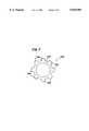
- FIG. 7shows an alternative cross-sectional piece suitable for use in accordance with the principles of the present invention, the piece includes a plurality of outer radial projections.
- FIG. 1Ashows an exemplary stent 120 that can be manufactured utilizing the principles of the present invention.
- the stent 120is but one example of many stents that can be manufactured using the general principles of the present invention.
- the stent 120has a relatively simple and consistent pattern of openings.
- the methods within the broad scope of the present inventioncan be utilized to manufacture stents or other tubular structures having a variety of opening patterns of wide ranging complexity.
- the stent 120is shown having struts with substantially rectangular cross-sections. It will be appreciated that by practicing the present invention, stents with struts having various cross-sectional shapes can be manufactured. Exemplary cross-sectional shapes include rounded shapes, curved shapes, asymmetrical shapes, hour-glass shapes, elliptical shapes, triangular shapes, or any other type of polygonal shapes.
- the stent 120comprises a generally tubular body 122 having a first end 124 opposite a second end 126.
- a central opening 128extends longitudinally between the first and second ends 124 and 126 of the body 122.
- a plurality of generally rectangular side openings 130extend transversely through the body 122.
- the rectangular side openings 130are defined by a plurality of longitudinal struts 132 that are interconnected by a plurality of transverse struts 134.
- the longitudinal struts 132 and the transverse struts 134together comprise the body 122 of the stent 120.
- FIG. 1Bshows a front view of the stent 120.
- the stent 120is divided into fifteen vertically stacked cross-sectional layers which have been assigned reference letters a-o.
- the thickness or height of each transverse strut 134has been selected so as to equal to the thickness of each of the defined fifteen layers.
- FIG. 1Cis a cross-sectional view of the stent 120 taken along section line 1C--1C. It will be appreciated that the cross-sectional view of FIG. 1C is representative of layers b-g and i-n.
- the stent 120has been divided into thirty-two evenly-spaced radial positions or sections which have been assigned reference numerals 1-32.
- the width of each radial positionis generally equal to the thickness of each lateral opening 130 and the width of each of the longitudinal strut members 132. As shown in FIG. 1C, each of the even radial positions is occupied by one of the longitudinal struts 132.
- FIG. 1Dprovides another cross-sectional view of the stent 120.
- the cross-sectional view of FIG. 1Dis representative of layers a and o of the stent 120.
- the stent 120has been divided into the same thirty-two evenly spaced radial positions previously described with respect to FIG. 1C.
- the transverse struts 134are configured to occupy radial positions 2-4, 6-8, 10-12, 14-16, 18-20, 22-24, 26-28, and 30-32.
- FIG. 1Eshows a further cross-sectional view of the stent 120.
- the cross-sectional view of FIG. 1eis representative of layer h of the stent 120.
- the cross-sectional viewshows the stent 120 divided into the same thirty-two equal radial positions.
- layer h of the stent 120has substantially the same cross-sectional configuration as layers a and o of the stent 120.
- the transverse strut configuration of layer hhas been rotated clockwise by two radial positions relative to the layers a and o. For example, as shown in FIG.
- the transverse struts 134 of layer hare configured to occupy radial positions 4-6, 8-10, 12-14, 16-18, 20-22, 24-26, 28-30, and 32-2.
- the transverse struts 134 of layer hare staggered with respect to the transverse struts of the layers a and o.
- the present inventionrelates generally to a method for manufacturing tube-like structures by cutting cross-sectional pieces from a flat sheet of material and then connecting the pieces together so they form individual cross-sectional layers of an elongated tube-like structure. It will be appreciated that the manufacturing technique of the present invention can be used to manufacture tube-like structures having varying configurations. Throughout the specification the various methods are described as being methods for manufacturing stents. However, it will be appreciated that the same methods are applicable for manufacturing a variety of other tubular medical devices configured to be inserted in a human body.
- An exemplary method for manufacturing the specific stent embodiment shown in FIG. 1a-1einvolves cutting each of the fifteen cross-sectional layers of the stent 120 from flat sheets of biocompatible material and then connecting the pieces together to form an elongated tube member.
- the sheetspreferably each have a thickness equal to the desired thickness of each cross-sectional layer of the stent 120.
- the sheets of biocompatible materialmay be made from a wide range of materials. Exemplary biocompatible materials include silver, tantalum, stainless steel, gold, titanium, nitinol, or any suitable plastic material. It will also be appreciated that the individual cross-sectional layers can be cut from the sheets of biocompatible material by a variety of cutting processes. Exemplary cutting techniques include stamping, electromechanical cutting, laser cutting, and chemical etching.
- FIG. 2Ashows an exemplary sheet 240 of biocompatible material.
- twelve first cross-sectional pieces 242 or washer structuresare cut from the sheet 240 (only one of the first pieces 242 is shown in FIG. 2A).
- the first pieces 242are used to manufacture layers b-g and i-n of the stent 120.
- Each of the cross-sectional pieces 242defines a generally circular central aperture 244 and includes radial portions 246 extending radially into the aperture 244.
- the radial portions 246are spaced circumferentially about the aperture 244 and define void spaces 248 located radially between each of the radial portions 246.
- Each first cross-sectional piece 242also includes a circular exterior boundary 250, a circular interior boundary 252, and a circular intermediate boundary 254 positioned between the interior and exterior boundaries 252 and 250.
- Each of the boundaries 250, 252 and 254are preferably concentrically aligned.
- the radial portions 246are preferably positioned between the interior boundary 252, which is defined by the interior sides of the radial portions 246, and the intermediate boundary 254 which is located where the radial portions 246 merge with the main body of the piece 242.
- An annular substantially solid exterior portion 255is defined between each intermediate boundary 254 and each exterior boundary 250.
- Keyway notches or slots 256are located at predetermined locations about the circumference of each exterior portion 255. Specifically, with respect to the first cross-sectional pieces 242, the keyway notches 256 are individually located adjacent to the first, ninth, seventeenth, and twenty-fifth radial positions.
- each intermediate boundary 254has a configuration that is substantially the same as the cross-sectional configuration of layers b-g and i-n of the stent 120.
- FIG. 2Bshows another sheet 340 of biocompatible material.
- two second cross-sectional pieces 342are cut from the sheet 340 (only one of the cross-sectional pieces is shown in FIG. 2C).
- the second pieces 342are configured to make layers a and o of the stent 120.
- Each of the second cross-sectional pieces 342has a generally angular shapes and defines a central aperture 344.
- the second pieces 342also include radial members 346 that extend radially into the apertures 344 and that are spaced about the circumference of the aperture 344. Void spaces 348 are located between the radial members 346.
- Each of the second cross-sectional pieces 342also includes a circular outer boundary 350, a circular inner boundary 352 defined by inner edges of radial members 346, and an intermediate boundary 354 positioned between the interior and exterior boundaries 352 and 350.
- the radial members or portions 346are positioned between the inner boundary 352 and the intermediate boundary 350. It will be appreciated that the radial portions 346 positioned inside of each intermediate boundary 354 have a configuration that is substantially the same as the cross-sectional configuration of layers a and o of the stent 120.
- a solid annular exterior portion 355is located between the exterior and intermediate boundaries 350 and 354.
- a plurality of keyways or notches 356are formed about the circumference of the exterior portion 355. For example, as shown in FIG. 2B, the notches 356 are radially aligned with the first, ninth, seventeenth, and twenty-fifth radial positions of the second cross-sectional pieces 342.
- FIG. 2Cshows a sheet 440 of biocompatible material having a third cross-sectional piece 442 cut therein.
- the third cross-sectional piece 442is configured to make or form layer h of the stent 120.
- the third cross-sectional piece 442has a generally annular shape and defines a generally circular interior aperture 444.
- Radial members 446project radially into the aperture 440 from the main body of the third piece 442.
- the radial members 442are uniformly spaced about a circumference of the aperture 444. Slots or void openings 448 are defined radially between each of the individual radial members 446.
- the third cross-sectional piece 442includes a circular exterior boundary 450, a circular interior boundary 452, and an intermediate boundary 454 positioned between the exterior and interior boundaries 450 and 452.
- the interior boundary 452is defined by inner edges of the radial members 446.
- the intermediate boundary 454is aligned along the region where the radial members 446 intersect with or connect to the main body of the third cross-sectional piece 442.
- the radial members 442are positioned between the interior boundary 452 and the intermediate boundary 454.
- An exterior portion 455 of the third cross-sectional piece 442is located between the intermediate boundary 454 and the exterior boundary 450.
- a plurality of keyways or notches 456are spaced about the circumference of the exterior portion 455. The notches 456 are shown aligned with the seventh, fifteenth, twenty-third, and thirty-second radial positions of the third cross-sectional piece 442.
- the third cross-sectional piece 442has substantially the same configuration as the second cross-sectional piece 342.
- the one substantial differences between the second and third cross-sectional pieces 342 and 442relates to the relative positioning of the keyways 356 and 456.
- the keyways 456 of the third cross-sectional piece 442have been rotated counterclockwise two radial positions relative to the keyways 356 of the second cross-sectional pieces 342.
- FIGS. 3A and 3Bshow the cross-sectional pieces 242, 342 and 442 aligned within a support structure.
- the support structureincludes four alignment members or posts 280 spaced about an outer circumference defined by the aligned cross-sectional pieces 242, 342 and 442.
- the posts 280have diameters slightly smaller than the size of the keyway notches 256, 356 and 456.
- the postsare fit within the keyways of the cross-sectional pieces 242, 342 and 442 to maintain the pieces in the aligned configuration.
- the posts 281also function to maintain a predetermined relative radial orientation between each of the individual cross-sectional pieces 242, 342 and 442. For example, the third piece 442 is shifted two radial positions relative to the second pieces 342
- the individual intermediate boundaries of the cross-sectional pieces 242, 342 and 442cooperate to form an elongated cylindrical intermediate boundary of the elongated member.
- the individual interior boundaries of the cross-sectional pieces 242, 342 and 442cooperate to form an elongated cylindrical internal boundary of the elongated member.
- the individual exterior boundaries of the cross-sectional pieces 242, 342 and 442cooperate to define an elongated cylindrical exterior boundary of the tube member.
- the pieces 242, 342 and 442are connected together.
- the individual cross-sectional pieces 242, 342 and 442are fused together such that the elongated tube comprises a one-piece unit.
- the piecescan be connected by techniques such as diffusion bonding, adhesive bonding, laser welding, and brazing.
- an connecting membermay extend through at least one radial member of each cross-sectional piece to connect the individual pieces together.
- FIGS. 4A and 4Bshow the resultant structure after the exterior portions 255, 355 and 455 have been removed. It will be appreciated that once the exterior portions 255, 355 and 455 are removed, only the radial portions 246, 346 and 446 of the cross-sectional pieces 42, 142 and 242 remain.
- the remaining radial portions 246, 346 and 446are preferably fused together and form a body of a stent having an outer diameter contiguous with the intermediate boundary of the elongate member and an inner diameter contiguous with the interior boundary of the elongated member.
- the void spaces 244, 344 and 444 between the radial portions 246, 346 and 446form transverse openings in the stent body.
- the resulting stent bodyhas exactly the same configuration as the stent 120 illustrated in FIGS. 1a-1e.
- the void spaces 248, 348 and 448cooperate to form the transverse openings 130 in the stent 120.
- the radial portions 246 of the twelve first pieces 242form the longitudinal struts 132 of the stent 120.
- the radial portions 346 of the two second pieces 342, and the radial portions 446 of the single third piece 442form the transverse struts 134 of the stent 120.
- FIGS. 5A-5Cillustrate alternative first, second, and third substantially flat annular pieces 500, 502, and 504 or washers.
- the first piece 500defines a plurality of first inner radial projections 506 having inner edges that define a first inner diameter d 1 .
- the second piece 502defines a plurality of second inner radial projections 508 that define a second inner diameter d 2 .
- the second projections 508project further inward than the first projections 506. Consequently, the second inner diameter d 2 is smaller than the first inner diameter d 1 .
- the third piece 504defines a plurality of third inner radial projections 510 that define a third inner diameter d 3 .
- the third projections 510project further inward than the second projections 508. Consequently, the third inner diameter d 3 is smaller than the second inner diameter d 2 .
- the pieces 500, 502, and 504are cut from a substantially flat section of biocompatible material. Then, as previously described with respect to the method shown by FIGS. 3A-4B, the pieces 500, 502, and 504, along with other pieces, are aligned or stacked on a support device to form a tubular structure.
- the pieces 500, 502, and 504form a portion of the tubular structure that has a tapered inner diameter defined by the inner edges of the radial projections 506, 508, and 510.
- the inner diameter variation between consecutive stacked piecesis gradual so as to provide a small inner diameter variation having desirable fluid flow characteristics.
- the pieces of the tube structureare connected together by exemplary techniques such as diffusion bonding, brazing, adhesive bonding and laser welding.
- an exterior portion of the tube structureis removed such that only the inner radial projections of the pieces remain.
- the remaining inner radial portions 506, 508, and 510form longitudinal struts of a stent.
- Such longitudinal strutshave cross-sectional areas which vary along the lengths of the struts.
- the inner edges of the strutsdefine an inner stent diameter which tapers along the length of the stent.
- each of the inner radial projections of a given annular piecehas the same cross-sectional configuration.
- selected inner radial projections of a given annular piececan have cross-sectional areas that are either larger or smaller than the remainder of the radial projection of the piece.
- such piecescan be used to manufacture stents having asymmetrical configurations. For example, a stent having a single strut that is thicker and more rigid than the remainder of the struts can be manufactured. Additionally, a stent having a single strut having a cross-section area than varies can be manufactured.
- the present inventionis not limited to manufacturing stents with single struts that vary in cross-sectional area with respect to the remaining struts.
- the present inventionallows each strut or cross-member of a stent to be manufactures with a unique cross sectional area and shape.
- the stentcan be designed having regions with varying flexibility and strength.
- FIG. 6shows alternative annular pieces 600 or washers suitable for use in accordance with the principles of the present invention.
- Each piece 600includes generally rectangular top recesses 602 defined between generally rectangular top projections 604.
- Each piece 600also includes generally rectangular bottom recesses 606 defined between generally rectangular bottom projections 608.
- the recesses 602, 606 and the projections 604, 608are uniformly spaced about the circumference of each piece 600.
- a continuous central portion or layer 610extends throughout each piece 600 between the top and bottom projections 604 and 608.
- the pieces 600are cut, preferably by an etching technique, from a substantially flat sheet of biocompatible material.
- the pieces 600are aligned or stacked on a support structure so as to form a tubular structure.
- the pieces 600are aligned so that the bottom projections 608 of a top piece align with the top projections 604 of a piece positioned directly below the top piece.
- the pieces 600are connected together.
- the pieces 600can be fused together.
- the pieces 600can be connected together by a connecting member 612 extending through each of the pieces 600.
- the connecting member 612preferably comprises an elongated member as a flexible wire, strand, fiber or thread.
- the connecting membercan comprise an elongated substantially rigid post or shaft.
- FIG. 7shows another alternative annular piece 700 suitable for use with a method of the present invention.
- the piece 700includes a solid inner portion 702 defining a central aperture 704.
- a plurality of outer radial projections 706are spaced about the circumference of the inner portion 702.
- the pieces 700are cut from a substantially flat sheet of biocompatible material.
- the pieces 700are then aligned on a support device such that the pieces 700 define an elongated tubular structure.
- the piecesare connected together by a technique such as diffusion bonding.
- the inner portion 702is removed, preferably by a machining process, and the interconnected radial projections 706 are left as a remainder.
- the remaining projections 706form the body, including interconnected struts and cross-members, of a tubular medical device such as a stent.
Landscapes
- Health & Medical Sciences (AREA)
- Engineering & Computer Science (AREA)
- Biomedical Technology (AREA)
- Heart & Thoracic Surgery (AREA)
- Life Sciences & Earth Sciences (AREA)
- Cardiology (AREA)
- Oral & Maxillofacial Surgery (AREA)
- Transplantation (AREA)
- Physics & Mathematics (AREA)
- Vascular Medicine (AREA)
- Optics & Photonics (AREA)
- Animal Behavior & Ethology (AREA)
- General Health & Medical Sciences (AREA)
- Public Health (AREA)
- Veterinary Medicine (AREA)
- Prostheses (AREA)
- Media Introduction/Drainage Providing Device (AREA)
Abstract
Description
Claims (23)
Priority Applications (3)
| Application Number | Priority Date | Filing Date | Title |
|---|---|---|---|
| US08/816,666US5815904A (en) | 1997-03-13 | 1997-03-13 | Method for making a stent |
| PCT/US1998/004956WO1998040187A1 (en) | 1997-03-13 | 1998-03-13 | Method for making a stent |
| AU65544/98AAU6554498A (en) | 1997-03-13 | 1998-03-13 | Method for making a stent |
Applications Claiming Priority (1)
| Application Number | Priority Date | Filing Date | Title |
|---|---|---|---|
| US08/816,666US5815904A (en) | 1997-03-13 | 1997-03-13 | Method for making a stent |
Publications (1)
| Publication Number | Publication Date |
|---|---|
| US5815904Atrue US5815904A (en) | 1998-10-06 |
Family
ID=25221312
Family Applications (1)
| Application Number | Title | Priority Date | Filing Date |
|---|---|---|---|
| US08/816,666Expired - LifetimeUS5815904A (en) | 1997-03-13 | 1997-03-13 | Method for making a stent |
Country Status (3)
| Country | Link |
|---|---|
| US (1) | US5815904A (en) |
| AU (1) | AU6554498A (en) |
| WO (1) | WO1998040187A1 (en) |
Cited By (43)
| Publication number | Priority date | Publication date | Assignee | Title |
|---|---|---|---|---|
| US6245102B1 (en) | 1997-05-07 | 2001-06-12 | Iowa-India Investments Company Ltd. | Stent, stent graft and stent valve |
| US6391502B1 (en) | 1998-09-23 | 2002-05-21 | Pemstar, Inc. | Photolithographic process for producing etched patterns on the surface of fine tubes, wires or other three dimensional structures |
| WO2002036045A3 (en)* | 2000-10-31 | 2002-09-12 | Scimed Life Systems Inc | Endoluminal device having superelastic and plastically deformable sections |
| US6613081B2 (en)* | 1997-11-14 | 2003-09-02 | Transvascular, Inc. | Deformable scaffolding multicellular stent |
| US20040000046A1 (en)* | 2002-06-27 | 2004-01-01 | Stinson Jonathan S. | Methods of making medical devices |
| US6723335B1 (en) | 2000-04-07 | 2004-04-20 | Jeffrey William Moehlenbruck | Methods and compositions for treating intervertebral disc degeneration |
| US20040181271A1 (en)* | 2003-03-10 | 2004-09-16 | Desimone Joseph M. | Intraluminal prostheses having polymeric material with selectively modified crystallinity and methods of making same |
| US6890350B1 (en) | 1999-07-28 | 2005-05-10 | Scimed Life Systems, Inc. | Combination self-expandable, balloon-expandable endoluminal device |
| US6955686B2 (en) | 2001-03-01 | 2005-10-18 | Cordis Corporation | Flexible stent |
| US6998060B2 (en) | 2001-03-01 | 2006-02-14 | Cordis Corporation | Flexible stent and method of manufacture |
| US20060095123A1 (en)* | 2004-11-04 | 2006-05-04 | Aiden Flanagan | Stent for delivering a therapeutic agent having increased body tissue contact surface |
| US7363926B2 (en) | 2002-12-30 | 2008-04-29 | Quiescence Medical, Inc. | Apparatus and methods for treating sleep apnea |
| US7381222B2 (en) | 2002-12-30 | 2008-06-03 | Quiescence Medical, Inc. | Stent for maintaining patency of a body region |
| US20080140176A1 (en)* | 2006-10-18 | 2008-06-12 | Krause Arthur A | Medical stent and devices for localized treatment of disease |
| US20080140187A1 (en)* | 2004-10-15 | 2008-06-12 | Krause Arthur A | Anti-clotting, anti-microbial, anti-inflammatory medical stent |
| US20090076591A1 (en)* | 2007-09-19 | 2009-03-19 | Boston Scientific Scimed, Inc. | Stent Design Allowing Extended Release of Drug and/or Enhanced Adhesion of Polymer to OD Surface |
| US20090198321A1 (en)* | 2008-02-01 | 2009-08-06 | Boston Scientific Scimed, Inc. | Drug-Coated Medical Devices for Differential Drug Release |
| US7579322B2 (en) | 2001-12-21 | 2009-08-25 | Zimmer Orthobiologics, Inc. | Compositions and methods for promoting myocardial and peripheral angiogenesis |
| US7594927B2 (en) | 2001-03-01 | 2009-09-29 | Cordis Corporation | Flexible stent |
| US7647931B2 (en) | 2002-12-30 | 2010-01-19 | Quiescence Medical, Inc. | Stent for maintaining patency of a body region |
| US20100050410A1 (en)* | 2008-09-02 | 2010-03-04 | Rolls-Royce Plc | Method of joining articles |
| US7833266B2 (en) | 2007-11-28 | 2010-11-16 | Boston Scientific Scimed, Inc. | Bifurcated stent with drug wells for specific ostial, carina, and side branch treatment |
| US7985252B2 (en) | 2008-07-30 | 2011-07-26 | Boston Scientific Scimed, Inc. | Bioerodible endoprosthesis |
| US7998192B2 (en) | 2008-05-09 | 2011-08-16 | Boston Scientific Scimed, Inc. | Endoprostheses |
| US8002821B2 (en) | 2006-09-18 | 2011-08-23 | Boston Scientific Scimed, Inc. | Bioerodible metallic ENDOPROSTHESES |
| US8048150B2 (en) | 2006-04-12 | 2011-11-01 | Boston Scientific Scimed, Inc. | Endoprosthesis having a fiber meshwork disposed thereon |
| US8052744B2 (en) | 2006-09-15 | 2011-11-08 | Boston Scientific Scimed, Inc. | Medical devices and methods of making the same |
| US8052743B2 (en) | 2006-08-02 | 2011-11-08 | Boston Scientific Scimed, Inc. | Endoprosthesis with three-dimensional disintegration control |
| US8052745B2 (en) | 2007-09-13 | 2011-11-08 | Boston Scientific Scimed, Inc. | Endoprosthesis |
| US8057534B2 (en) | 2006-09-15 | 2011-11-15 | Boston Scientific Scimed, Inc. | Bioerodible endoprostheses and methods of making the same |
| US8080055B2 (en) | 2006-12-28 | 2011-12-20 | Boston Scientific Scimed, Inc. | Bioerodible endoprostheses and methods of making the same |
| US8089029B2 (en) | 2006-02-01 | 2012-01-03 | Boston Scientific Scimed, Inc. | Bioabsorbable metal medical device and method of manufacture |
| US8128689B2 (en) | 2006-09-15 | 2012-03-06 | Boston Scientific Scimed, Inc. | Bioerodible endoprosthesis with biostable inorganic layers |
| US8146600B2 (en) | 2003-07-22 | 2012-04-03 | Quiescence Medical, Inc. | Apparatus and methods for treating sleep apnea |
| US8236046B2 (en) | 2008-06-10 | 2012-08-07 | Boston Scientific Scimed, Inc. | Bioerodible endoprosthesis |
| US8267992B2 (en) | 2009-03-02 | 2012-09-18 | Boston Scientific Scimed, Inc. | Self-buffering medical implants |
| US8303643B2 (en) | 2001-06-27 | 2012-11-06 | Remon Medical Technologies Ltd. | Method and device for electrochemical formation of therapeutic species in vivo |
| US8382824B2 (en) | 2008-10-03 | 2013-02-26 | Boston Scientific Scimed, Inc. | Medical implant having NANO-crystal grains with barrier layers of metal nitrides or fluorides |
| US8668732B2 (en) | 2010-03-23 | 2014-03-11 | Boston Scientific Scimed, Inc. | Surface treated bioerodible metal endoprostheses |
| US8808726B2 (en) | 2006-09-15 | 2014-08-19 | Boston Scientific Scimed. Inc. | Bioerodible endoprostheses and methods of making the same |
| US8840660B2 (en) | 2006-01-05 | 2014-09-23 | Boston Scientific Scimed, Inc. | Bioerodible endoprostheses and methods of making the same |
| US9127786B1 (en) | 2014-05-05 | 2015-09-08 | Anselmo Arratia | Vascular surgical clamp for holding and guiding guide wire on a sterile field |
| US9265649B2 (en) | 2010-12-13 | 2016-02-23 | Quiescence Medical, Inc. | Apparatus and methods for treating sleep apnea |
Families Citing this family (1)
| Publication number | Priority date | Publication date | Assignee | Title |
|---|---|---|---|---|
| DE10113706B4 (en)* | 2001-03-16 | 2005-04-28 | Aesculap Ag & Co Kg | Medical instrument and method for manufacturing a medical instrument |
Citations (8)
| Publication number | Priority date | Publication date | Assignee | Title |
|---|---|---|---|---|
| US4434546A (en)* | 1979-09-21 | 1984-03-06 | General Electric Company | Method of making a core |
| US4610068A (en)* | 1985-07-17 | 1986-09-09 | Eastman Kodak Company | Method for forming a ribbon blender |
| US4866826A (en)* | 1987-12-22 | 1989-09-19 | Makoto Koide | Method of making squeezing roll and squeezing equipment |
| US5195984A (en)* | 1988-10-04 | 1993-03-23 | Expandable Grafts Partnership | Expandable intraluminal graft |
| US5354309A (en)* | 1991-10-11 | 1994-10-11 | Angiomed Ag | Apparatus for widening a stenosis in a body cavity |
| US5693085A (en)* | 1994-04-29 | 1997-12-02 | Scimed Life Systems, Inc. | Stent with collagen |
| US5713949A (en)* | 1996-08-06 | 1998-02-03 | Jayaraman; Swaminathan | Microporous covered stents and method of coating |
| US5733303A (en)* | 1994-03-17 | 1998-03-31 | Medinol Ltd. | Flexible expandable stent |
- 1997
- 1997-03-13USUS08/816,666patent/US5815904A/ennot_activeExpired - Lifetime
- 1998
- 1998-03-13AUAU65544/98Apatent/AU6554498A/ennot_activeAbandoned
- 1998-03-13WOPCT/US1998/004956patent/WO1998040187A1/enactiveApplication Filing
Patent Citations (8)
| Publication number | Priority date | Publication date | Assignee | Title |
|---|---|---|---|---|
| US4434546A (en)* | 1979-09-21 | 1984-03-06 | General Electric Company | Method of making a core |
| US4610068A (en)* | 1985-07-17 | 1986-09-09 | Eastman Kodak Company | Method for forming a ribbon blender |
| US4866826A (en)* | 1987-12-22 | 1989-09-19 | Makoto Koide | Method of making squeezing roll and squeezing equipment |
| US5195984A (en)* | 1988-10-04 | 1993-03-23 | Expandable Grafts Partnership | Expandable intraluminal graft |
| US5354309A (en)* | 1991-10-11 | 1994-10-11 | Angiomed Ag | Apparatus for widening a stenosis in a body cavity |
| US5733303A (en)* | 1994-03-17 | 1998-03-31 | Medinol Ltd. | Flexible expandable stent |
| US5693085A (en)* | 1994-04-29 | 1997-12-02 | Scimed Life Systems, Inc. | Stent with collagen |
| US5713949A (en)* | 1996-08-06 | 1998-02-03 | Jayaraman; Swaminathan | Microporous covered stents and method of coating |
Cited By (58)
| Publication number | Priority date | Publication date | Assignee | Title |
|---|---|---|---|---|
| US6245102B1 (en) | 1997-05-07 | 2001-06-12 | Iowa-India Investments Company Ltd. | Stent, stent graft and stent valve |
| US6613081B2 (en)* | 1997-11-14 | 2003-09-02 | Transvascular, Inc. | Deformable scaffolding multicellular stent |
| US20040015225A1 (en)* | 1997-11-14 | 2004-01-22 | Kim Steven W. | Deformable scaffolding multicellular stent |
| US6863684B2 (en) | 1997-11-14 | 2005-03-08 | Medtronic Vascular, Inc. | Deformable scaffolding multicellular stent |
| US6391502B1 (en) | 1998-09-23 | 2002-05-21 | Pemstar, Inc. | Photolithographic process for producing etched patterns on the surface of fine tubes, wires or other three dimensional structures |
| US6542218B2 (en) | 1998-09-23 | 2003-04-01 | Pemstar, Inc. | Photolithographic process for producing etched patterns on the surface of fine tubes, wires, or other three dimensional structures |
| US6890350B1 (en) | 1999-07-28 | 2005-05-10 | Scimed Life Systems, Inc. | Combination self-expandable, balloon-expandable endoluminal device |
| US6723335B1 (en) | 2000-04-07 | 2004-04-20 | Jeffrey William Moehlenbruck | Methods and compositions for treating intervertebral disc degeneration |
| US7556649B2 (en) | 2000-04-07 | 2009-07-07 | Zimmer Orthobiologics, Inc. | Methods and compositions for treating intervertebral disc degeneration |
| WO2002036045A3 (en)* | 2000-10-31 | 2002-09-12 | Scimed Life Systems Inc | Endoluminal device having superelastic and plastically deformable sections |
| US6998060B2 (en) | 2001-03-01 | 2006-02-14 | Cordis Corporation | Flexible stent and method of manufacture |
| US6955686B2 (en) | 2001-03-01 | 2005-10-18 | Cordis Corporation | Flexible stent |
| US7594927B2 (en) | 2001-03-01 | 2009-09-29 | Cordis Corporation | Flexible stent |
| US20060036312A1 (en)* | 2001-03-01 | 2006-02-16 | Tomonto Charles V | Flexible stent and method of manufacture |
| US8303643B2 (en) | 2001-06-27 | 2012-11-06 | Remon Medical Technologies Ltd. | Method and device for electrochemical formation of therapeutic species in vivo |
| US7579322B2 (en) | 2001-12-21 | 2009-08-25 | Zimmer Orthobiologics, Inc. | Compositions and methods for promoting myocardial and peripheral angiogenesis |
| US6865810B2 (en) | 2002-06-27 | 2005-03-15 | Scimed Life Systems, Inc. | Methods of making medical devices |
| US20040000046A1 (en)* | 2002-06-27 | 2004-01-01 | Stinson Jonathan S. | Methods of making medical devices |
| US7381222B2 (en) | 2002-12-30 | 2008-06-03 | Quiescence Medical, Inc. | Stent for maintaining patency of a body region |
| US7363926B2 (en) | 2002-12-30 | 2008-04-29 | Quiescence Medical, Inc. | Apparatus and methods for treating sleep apnea |
| US8578938B2 (en) | 2002-12-30 | 2013-11-12 | Quiescence Medical, Inc. | Apparatus and methods for treating sleep apnea |
| US8104478B2 (en) | 2002-12-30 | 2012-01-31 | Quiescence Medical, Inc. | Apparatus and methods for treating sleep apnea |
| US8939145B2 (en) | 2002-12-30 | 2015-01-27 | Quiescence Medical, Inc. | Apparatus and methods for treating sleep apnea |
| US7992566B2 (en) | 2002-12-30 | 2011-08-09 | Quiescence Medical, Inc. | Apparatus and methods for treating sleep apnea |
| US7647931B2 (en) | 2002-12-30 | 2010-01-19 | Quiescence Medical, Inc. | Stent for maintaining patency of a body region |
| US20040181271A1 (en)* | 2003-03-10 | 2004-09-16 | Desimone Joseph M. | Intraluminal prostheses having polymeric material with selectively modified crystallinity and methods of making same |
| US6932930B2 (en)* | 2003-03-10 | 2005-08-23 | Synecor, Llc | Intraluminal prostheses having polymeric material with selectively modified crystallinity and methods of making same |
| US8146600B2 (en) | 2003-07-22 | 2012-04-03 | Quiescence Medical, Inc. | Apparatus and methods for treating sleep apnea |
| US20080140187A1 (en)* | 2004-10-15 | 2008-06-12 | Krause Arthur A | Anti-clotting, anti-microbial, anti-inflammatory medical stent |
| US7628807B2 (en) | 2004-11-04 | 2009-12-08 | Boston Scientific Scimed, Inc. | Stent for delivering a therapeutic agent having increased body tissue contact surface |
| US20060095123A1 (en)* | 2004-11-04 | 2006-05-04 | Aiden Flanagan | Stent for delivering a therapeutic agent having increased body tissue contact surface |
| WO2006052574A3 (en)* | 2004-11-04 | 2006-09-14 | Boston Scient Scimed Inc | Stent for delivering a therapeutic agent |
| US8840660B2 (en) | 2006-01-05 | 2014-09-23 | Boston Scientific Scimed, Inc. | Bioerodible endoprostheses and methods of making the same |
| US8089029B2 (en) | 2006-02-01 | 2012-01-03 | Boston Scientific Scimed, Inc. | Bioabsorbable metal medical device and method of manufacture |
| US8048150B2 (en) | 2006-04-12 | 2011-11-01 | Boston Scientific Scimed, Inc. | Endoprosthesis having a fiber meshwork disposed thereon |
| US8052743B2 (en) | 2006-08-02 | 2011-11-08 | Boston Scientific Scimed, Inc. | Endoprosthesis with three-dimensional disintegration control |
| US8128689B2 (en) | 2006-09-15 | 2012-03-06 | Boston Scientific Scimed, Inc. | Bioerodible endoprosthesis with biostable inorganic layers |
| US8057534B2 (en) | 2006-09-15 | 2011-11-15 | Boston Scientific Scimed, Inc. | Bioerodible endoprostheses and methods of making the same |
| US8052744B2 (en) | 2006-09-15 | 2011-11-08 | Boston Scientific Scimed, Inc. | Medical devices and methods of making the same |
| US8808726B2 (en) | 2006-09-15 | 2014-08-19 | Boston Scientific Scimed. Inc. | Bioerodible endoprostheses and methods of making the same |
| US8002821B2 (en) | 2006-09-18 | 2011-08-23 | Boston Scientific Scimed, Inc. | Bioerodible metallic ENDOPROSTHESES |
| US20080140176A1 (en)* | 2006-10-18 | 2008-06-12 | Krause Arthur A | Medical stent and devices for localized treatment of disease |
| US8080055B2 (en) | 2006-12-28 | 2011-12-20 | Boston Scientific Scimed, Inc. | Bioerodible endoprostheses and methods of making the same |
| US8715339B2 (en) | 2006-12-28 | 2014-05-06 | Boston Scientific Scimed, Inc. | Bioerodible endoprostheses and methods of making the same |
| US8052745B2 (en) | 2007-09-13 | 2011-11-08 | Boston Scientific Scimed, Inc. | Endoprosthesis |
| US20090076591A1 (en)* | 2007-09-19 | 2009-03-19 | Boston Scientific Scimed, Inc. | Stent Design Allowing Extended Release of Drug and/or Enhanced Adhesion of Polymer to OD Surface |
| US7833266B2 (en) | 2007-11-28 | 2010-11-16 | Boston Scientific Scimed, Inc. | Bifurcated stent with drug wells for specific ostial, carina, and side branch treatment |
| US20090198321A1 (en)* | 2008-02-01 | 2009-08-06 | Boston Scientific Scimed, Inc. | Drug-Coated Medical Devices for Differential Drug Release |
| US7998192B2 (en) | 2008-05-09 | 2011-08-16 | Boston Scientific Scimed, Inc. | Endoprostheses |
| US8236046B2 (en) | 2008-06-10 | 2012-08-07 | Boston Scientific Scimed, Inc. | Bioerodible endoprosthesis |
| US7985252B2 (en) | 2008-07-30 | 2011-07-26 | Boston Scientific Scimed, Inc. | Bioerodible endoprosthesis |
| US8109431B2 (en)* | 2008-09-02 | 2012-02-07 | Rolls-Royce Plc | Method of joining articles using adjustment features |
| US20100050410A1 (en)* | 2008-09-02 | 2010-03-04 | Rolls-Royce Plc | Method of joining articles |
| US8382824B2 (en) | 2008-10-03 | 2013-02-26 | Boston Scientific Scimed, Inc. | Medical implant having NANO-crystal grains with barrier layers of metal nitrides or fluorides |
| US8267992B2 (en) | 2009-03-02 | 2012-09-18 | Boston Scientific Scimed, Inc. | Self-buffering medical implants |
| US8668732B2 (en) | 2010-03-23 | 2014-03-11 | Boston Scientific Scimed, Inc. | Surface treated bioerodible metal endoprostheses |
| US9265649B2 (en) | 2010-12-13 | 2016-02-23 | Quiescence Medical, Inc. | Apparatus and methods for treating sleep apnea |
| US9127786B1 (en) | 2014-05-05 | 2015-09-08 | Anselmo Arratia | Vascular surgical clamp for holding and guiding guide wire on a sterile field |
Also Published As
| Publication number | Publication date |
|---|---|
| AU6554498A (en) | 1998-09-29 |
| WO1998040187A1 (en) | 1998-09-17 |
Similar Documents
| Publication | Publication Date | Title |
|---|---|---|
| US5815904A (en) | Method for making a stent | |
| US5911752A (en) | Method for collapsing a stent | |
| US6436133B1 (en) | Expandable graft | |
| DE69731514T2 (en) | Expandable stent | |
| US7637938B2 (en) | Flexible stent | |
| US6117165A (en) | Expandable intraluminal endoprosthesis | |
| US8236043B2 (en) | Stent | |
| JP4659159B2 (en) | Bifurcated stent and manufacturing method thereof | |
| US5716393A (en) | Stent with an end of greater diameter than its main body | |
| US8382820B2 (en) | Stent having helical elements | |
| US5897588A (en) | Coronary stent and method of fabricating same | |
| US20020156525A1 (en) | Spiral wound stent | |
| WO1996029028A1 (en) | Expandable surgical stent | |
| EP0962194A2 (en) | Expandable stent having articulated connecting rods | |
| EP1970033A2 (en) | Improved longitudinally flexible expandable stent | |
| US20060252624A1 (en) | Deployable stent | |
| EP1236448A2 (en) | Flexible stent | |
| EP1813224A2 (en) | Self-expandable shape memory alloy stent and method for fabricating the same | |
| WO1998041168A1 (en) | Coronary stent and method of fabricating same | |
| DE60211999T2 (en) | Flexible stent | |
| US8961590B2 (en) | Flexible helical stent having different helical regions | |
| US8808354B2 (en) | Helical stent | |
| WO2007124145A9 (en) | Dedicated bifurcation stent apparatus and method | |
| WO2025177315A2 (en) | Stent implant | |
| GB2369062A (en) | Extendable stent |
Legal Events
| Date | Code | Title | Description |
|---|---|---|---|
| AS | Assignment | Owner name:CARDIA CATHETER COMPANY, MINNESOTA Free format text:ASSIGNMENT OF ASSIGNORS INTEREST;ASSIGNORS:CLUBB, THOMAS L.;DONADIO, JAMES V., III;DUSTRUDE, MARK O.;AND OTHERS;REEL/FRAME:008694/0313;SIGNING DATES FROM 19970812 TO 19970826 | |
| AS | Assignment | Owner name:INTRATHERAPEUTICS, INC., MINNESOTA Free format text:CHANGE OF NAME;ASSIGNOR:CARDIA CATHETER COMPANY;REEL/FRAME:009323/0949 Effective date:19970905 | |
| STCF | Information on status: patent grant | Free format text:PATENTED CASE | |
| AS | Assignment | Owner name:WELLS FARGO BUSINESS CREDIT, INC., MINNESOTA Free format text:NOTICE OF NON-EXCLUSIVE LICENSE OF U.S. PATENTS.;ASSIGNOR:INTRATHERAPEUTICS, INC.;REEL/FRAME:010263/0637 Effective date:19990921 | |
| AS | Assignment | Owner name:INTRATHERAPEUTICS, INC., MINNESOTA Free format text:RELEASE OF SECURITY INTEREST;ASSIGNOR:WELLS FARGO BUSINESS CREDIT, INC.;REEL/FRAME:011911/0271 Effective date:20010321 | |
| FEPP | Fee payment procedure | Free format text:PAYER NUMBER DE-ASSIGNED (ORIGINAL EVENT CODE: RMPN); ENTITY STATUS OF PATENT OWNER: LARGE ENTITY Free format text:PAYOR NUMBER ASSIGNED (ORIGINAL EVENT CODE: ASPN); ENTITY STATUS OF PATENT OWNER: LARGE ENTITY | |
| FPAY | Fee payment | Year of fee payment:4 | |
| REMI | Maintenance fee reminder mailed | ||
| AS | Assignment | Owner name:EV3 PERIPHERAL, INC., MINNESOTA Free format text:CHANGE OF NAME;ASSIGNOR:SULZER INTRATHERAPEUTICS, INC.;REEL/FRAME:014327/0092 Effective date:20021227 Owner name:SULZER INTRA THERAPEUTICS, INC., MINNESOTA Free format text:CHANGE OF NAME;ASSIGNOR:INTRA THERAPEUTICS, INC.;REEL/FRAME:014337/0413 Effective date:20010201 | |
| FEPP | Fee payment procedure | Free format text:PAT HOLDER NO LONGER CLAIMS SMALL ENTITY STATUS, ENTITY STATUS SET TO UNDISCOUNTED (ORIGINAL EVENT CODE: STOL); ENTITY STATUS OF PATENT OWNER: LARGE ENTITY | |
| FPAY | Fee payment | Year of fee payment:8 | |
| FPAY | Fee payment | Year of fee payment:12 |