US5814175A - Welded thermoplastic polymer article and a method and apparatus for making same - Google Patents
Welded thermoplastic polymer article and a method and apparatus for making sameDownload PDFInfo
- Publication number
- US5814175A US5814175AUS08/480,799US48079995AUS5814175AUS 5814175 AUS5814175 AUS 5814175AUS 48079995 AUS48079995 AUS 48079995AUS 5814175 AUS5814175 AUS 5814175A
- Authority
- US
- United States
- Prior art keywords
- heating element
- enclosure
- sheets
- air
- edges
- Prior art date
- Legal status (The legal status is an assumption and is not a legal conclusion. Google has not performed a legal analysis and makes no representation as to the accuracy of the status listed.)
- Expired - Lifetime
Links
- 238000000034methodMethods0.000titleclaimsabstractdescription44
- 229920001169thermoplasticPolymers0.000titleclaimsabstractdescription12
- 238000003466weldingMethods0.000claimsabstractdescription37
- 238000010438heat treatmentMethods0.000claimsdescription60
- 239000000463materialSubstances0.000claimsdescription51
- 229920002313fluoropolymerPolymers0.000claimsdescription40
- 239000004811fluoropolymerSubstances0.000claimsdescription34
- 239000012815thermoplastic materialSubstances0.000claimsdescription16
- -1polytetrafluoroethylenePolymers0.000claimsdescription9
- 229920001343polytetrafluoroethylenePolymers0.000claimsdescription7
- 239000004810polytetrafluoroethyleneSubstances0.000claimsdescription7
- 239000004416thermosoftening plasticSubstances0.000claimsdescription6
- 229910052751metalInorganic materials0.000claimsdescription5
- 239000002184metalSubstances0.000claimsdescription5
- 230000004888barrier functionEffects0.000claimsdescription4
- 230000003213activating effectEffects0.000claimsdescription3
- 239000004642PolyimideSubstances0.000claimsdescription2
- 229920001721polyimidePolymers0.000claimsdescription2
- 238000010348incorporationMethods0.000claims2
- 239000010410layerSubstances0.000claims2
- 239000011148porous materialSubstances0.000claims2
- 239000011241protective layerSubstances0.000claims1
- 230000008569processEffects0.000abstractdescription19
- 229920000642polymerPolymers0.000abstractdescription7
- 230000009969flowable effectEffects0.000abstract1
- 239000012528membraneSubstances0.000description26
- 239000000853adhesiveSubstances0.000description14
- 230000001070adhesive effectEffects0.000description14
- 230000004927fusionEffects0.000description10
- 239000000945fillerSubstances0.000description9
- 239000012212insulatorSubstances0.000description6
- 238000005304joiningMethods0.000description6
- 230000007797corrosionEffects0.000description5
- 238000005260corrosionMethods0.000description5
- 239000004033plasticSubstances0.000description5
- 229920003023plasticPolymers0.000description5
- 229920001774PerfluoroetherPolymers0.000description4
- 239000011888foilSubstances0.000description4
- 229920005989resinPolymers0.000description4
- 239000011347resinSubstances0.000description4
- 229920001577copolymerPolymers0.000description3
- 239000004744fabricSubstances0.000description3
- 239000004593EpoxySubstances0.000description2
- 239000004812Fluorinated ethylene propyleneSubstances0.000description2
- XEEYBQQBJWHFJM-UHFFFAOYSA-NIronChemical compound[Fe]XEEYBQQBJWHFJM-UHFFFAOYSA-N0.000description2
- PXHVJJICTQNCMI-UHFFFAOYSA-NNickelChemical compound[Ni]PXHVJJICTQNCMI-UHFFFAOYSA-N0.000description2
- 229910018487Ni—CrInorganic materials0.000description2
- QAOWNCQODCNURD-UHFFFAOYSA-NSulfuric acidChemical compoundOS(O)(=O)=OQAOWNCQODCNURD-UHFFFAOYSA-N0.000description2
- 238000004026adhesive bondingMethods0.000description2
- 238000010420art techniqueMethods0.000description2
- 230000008901benefitEffects0.000description2
- VNNRSPGTAMTISX-UHFFFAOYSA-Nchromium nickelChemical compound[Cr].[Ni]VNNRSPGTAMTISX-UHFFFAOYSA-N0.000description2
- 239000000356contaminantSubstances0.000description2
- 230000001276controlling effectEffects0.000description2
- 230000007547defectEffects0.000description2
- 238000011161developmentMethods0.000description2
- 230000018109developmental processEffects0.000description2
- 230000000694effectsEffects0.000description2
- 229920000840ethylene tetrafluoroethylene copolymerPolymers0.000description2
- 239000011152fibreglassSubstances0.000description2
- 239000007789gasSubstances0.000description2
- 239000011521glassSubstances0.000description2
- 229920001519homopolymerPolymers0.000description2
- 238000002844meltingMethods0.000description2
- 230000008018meltingEffects0.000description2
- 229920006284nylon filmPolymers0.000description2
- 229920009441perflouroethylene propylenePolymers0.000description2
- 229920003223poly(pyromellitimide-1,4-diphenyl ether)Polymers0.000description2
- 229920001296polysiloxanePolymers0.000description2
- 229920002620polyvinyl fluoridePolymers0.000description2
- 229920002981polyvinylidene fluoridePolymers0.000description2
- 230000001105regulatory effectEffects0.000description2
- 239000000126substanceSubstances0.000description2
- 229920002994synthetic fiberPolymers0.000description2
- BQCIDUSAKPWEOX-UHFFFAOYSA-N1,1-DifluoroetheneChemical compoundFC(F)=CBQCIDUSAKPWEOX-UHFFFAOYSA-N0.000description1
- PXGOKWXKJXAPGV-UHFFFAOYSA-NFluorineChemical compoundFFPXGOKWXKJXAPGV-UHFFFAOYSA-N0.000description1
- UFHFLCQGNIYNRP-UHFFFAOYSA-NHydrogenChemical compound[H][H]UFHFLCQGNIYNRP-UHFFFAOYSA-N0.000description1
- GRYLNZFGIOXLOG-UHFFFAOYSA-NNitric acidChemical compoundO[N+]([O-])=OGRYLNZFGIOXLOG-UHFFFAOYSA-N0.000description1
- 229910000746Structural steelInorganic materials0.000description1
- 238000009825accumulationMethods0.000description1
- 239000010953base metalSubstances0.000description1
- 230000015572biosynthetic processEffects0.000description1
- 229920001400block copolymerPolymers0.000description1
- 230000015556catabolic processEffects0.000description1
- 238000001816coolingMethods0.000description1
- 230000006378damageEffects0.000description1
- 230000007812deficiencyEffects0.000description1
- 238000006731degradation reactionMethods0.000description1
- 230000001419dependent effectEffects0.000description1
- 230000006866deteriorationEffects0.000description1
- 230000008030eliminationEffects0.000description1
- 238000003379elimination reactionMethods0.000description1
- 125000003700epoxy groupChemical group0.000description1
- HQQADJVZYDDRJT-UHFFFAOYSA-Nethene;prop-1-eneChemical groupC=C.CC=CHQQADJVZYDDRJT-UHFFFAOYSA-N0.000description1
- 239000011737fluorineSubstances0.000description1
- 229910052731fluorineInorganic materials0.000description1
- NBVXSUQYWXRMNV-UHFFFAOYSA-NfluoromethaneChemical compoundFCNBVXSUQYWXRMNV-UHFFFAOYSA-N0.000description1
- 229920000578graft copolymerPolymers0.000description1
- 239000001257hydrogenSubstances0.000description1
- 229910052739hydrogenInorganic materials0.000description1
- 230000006872improvementEffects0.000description1
- 239000011261inert gasSubstances0.000description1
- 238000009434installationMethods0.000description1
- 238000009413insulationMethods0.000description1
- 229910052742ironInorganic materials0.000description1
- 238000003754machiningMethods0.000description1
- 229910001092metal group alloyInorganic materials0.000description1
- 150000002739metalsChemical class0.000description1
- 239000000203mixtureSubstances0.000description1
- 230000004048modificationEffects0.000description1
- 238000012986modificationMethods0.000description1
- 229910052759nickelInorganic materials0.000description1
- 229910017604nitric acidInorganic materials0.000description1
- 239000000615nonconductorSubstances0.000description1
- 230000037361pathwayEffects0.000description1
- 229920000647polyepoxidePolymers0.000description1
- 238000007789sealingMethods0.000description1
- 238000007493shaping processMethods0.000description1
- 239000010935stainless steelSubstances0.000description1
- 229910001220stainless steelInorganic materials0.000description1
- 238000003860storageMethods0.000description1
- 229920005992thermoplastic resinPolymers0.000description1
Images


Classifications
- B—PERFORMING OPERATIONS; TRANSPORTING
- B29—WORKING OF PLASTICS; WORKING OF SUBSTANCES IN A PLASTIC STATE IN GENERAL
- B29C—SHAPING OR JOINING OF PLASTICS; SHAPING OF MATERIAL IN A PLASTIC STATE, NOT OTHERWISE PROVIDED FOR; AFTER-TREATMENT OF THE SHAPED PRODUCTS, e.g. REPAIRING
- B29C65/00—Joining or sealing of preformed parts, e.g. welding of plastics materials; Apparatus therefor
- B29C65/02—Joining or sealing of preformed parts, e.g. welding of plastics materials; Apparatus therefor by heating, with or without pressure
- B29C65/18—Joining or sealing of preformed parts, e.g. welding of plastics materials; Apparatus therefor by heating, with or without pressure using heated tools
- B—PERFORMING OPERATIONS; TRANSPORTING
- B29—WORKING OF PLASTICS; WORKING OF SUBSTANCES IN A PLASTIC STATE IN GENERAL
- B29C—SHAPING OR JOINING OF PLASTICS; SHAPING OF MATERIAL IN A PLASTIC STATE, NOT OTHERWISE PROVIDED FOR; AFTER-TREATMENT OF THE SHAPED PRODUCTS, e.g. REPAIRING
- B29C65/00—Joining or sealing of preformed parts, e.g. welding of plastics materials; Apparatus therefor
- B29C65/48—Joining or sealing of preformed parts, e.g. welding of plastics materials; Apparatus therefor using adhesives, i.e. using supplementary joining material; solvent bonding
- B29C65/50—Joining or sealing of preformed parts, e.g. welding of plastics materials; Apparatus therefor using adhesives, i.e. using supplementary joining material; solvent bonding using adhesive tape, e.g. thermoplastic tape; using threads or the like
- B29C65/5007—Joining or sealing of preformed parts, e.g. welding of plastics materials; Apparatus therefor using adhesives, i.e. using supplementary joining material; solvent bonding using adhesive tape, e.g. thermoplastic tape; using threads or the like characterised by the structure of said adhesive tape, threads or the like
- B29C65/5021—Joining or sealing of preformed parts, e.g. welding of plastics materials; Apparatus therefor using adhesives, i.e. using supplementary joining material; solvent bonding using adhesive tape, e.g. thermoplastic tape; using threads or the like characterised by the structure of said adhesive tape, threads or the like being multi-layered
- B—PERFORMING OPERATIONS; TRANSPORTING
- B29—WORKING OF PLASTICS; WORKING OF SUBSTANCES IN A PLASTIC STATE IN GENERAL
- B29C—SHAPING OR JOINING OF PLASTICS; SHAPING OF MATERIAL IN A PLASTIC STATE, NOT OTHERWISE PROVIDED FOR; AFTER-TREATMENT OF THE SHAPED PRODUCTS, e.g. REPAIRING
- B29C65/00—Joining or sealing of preformed parts, e.g. welding of plastics materials; Apparatus therefor
- B29C65/48—Joining or sealing of preformed parts, e.g. welding of plastics materials; Apparatus therefor using adhesives, i.e. using supplementary joining material; solvent bonding
- B29C65/50—Joining or sealing of preformed parts, e.g. welding of plastics materials; Apparatus therefor using adhesives, i.e. using supplementary joining material; solvent bonding using adhesive tape, e.g. thermoplastic tape; using threads or the like
- B29C65/5007—Joining or sealing of preformed parts, e.g. welding of plastics materials; Apparatus therefor using adhesives, i.e. using supplementary joining material; solvent bonding using adhesive tape, e.g. thermoplastic tape; using threads or the like characterised by the structure of said adhesive tape, threads or the like
- B29C65/5028—Joining or sealing of preformed parts, e.g. welding of plastics materials; Apparatus therefor using adhesives, i.e. using supplementary joining material; solvent bonding using adhesive tape, e.g. thermoplastic tape; using threads or the like characterised by the structure of said adhesive tape, threads or the like being textile in woven or non-woven form
- B—PERFORMING OPERATIONS; TRANSPORTING
- B29—WORKING OF PLASTICS; WORKING OF SUBSTANCES IN A PLASTIC STATE IN GENERAL
- B29C—SHAPING OR JOINING OF PLASTICS; SHAPING OF MATERIAL IN A PLASTIC STATE, NOT OTHERWISE PROVIDED FOR; AFTER-TREATMENT OF THE SHAPED PRODUCTS, e.g. REPAIRING
- B29C65/00—Joining or sealing of preformed parts, e.g. welding of plastics materials; Apparatus therefor
- B29C65/48—Joining or sealing of preformed parts, e.g. welding of plastics materials; Apparatus therefor using adhesives, i.e. using supplementary joining material; solvent bonding
- B29C65/50—Joining or sealing of preformed parts, e.g. welding of plastics materials; Apparatus therefor using adhesives, i.e. using supplementary joining material; solvent bonding using adhesive tape, e.g. thermoplastic tape; using threads or the like
- B29C65/5042—Joining or sealing of preformed parts, e.g. welding of plastics materials; Apparatus therefor using adhesives, i.e. using supplementary joining material; solvent bonding using adhesive tape, e.g. thermoplastic tape; using threads or the like covering both elements to be joined
- B—PERFORMING OPERATIONS; TRANSPORTING
- B29—WORKING OF PLASTICS; WORKING OF SUBSTANCES IN A PLASTIC STATE IN GENERAL
- B29C—SHAPING OR JOINING OF PLASTICS; SHAPING OF MATERIAL IN A PLASTIC STATE, NOT OTHERWISE PROVIDED FOR; AFTER-TREATMENT OF THE SHAPED PRODUCTS, e.g. REPAIRING
- B29C66/00—General aspects of processes or apparatus for joining preformed parts
- B29C66/004—Preventing sticking together, e.g. of some areas of the parts to be joined
- B29C66/0042—Preventing sticking together, e.g. of some areas of the parts to be joined of the joining tool and the parts to be joined
- B29C66/0044—Preventing sticking together, e.g. of some areas of the parts to be joined of the joining tool and the parts to be joined using a separating sheet, e.g. fixed on the joining tool
- B—PERFORMING OPERATIONS; TRANSPORTING
- B29—WORKING OF PLASTICS; WORKING OF SUBSTANCES IN A PLASTIC STATE IN GENERAL
- B29C—SHAPING OR JOINING OF PLASTICS; SHAPING OF MATERIAL IN A PLASTIC STATE, NOT OTHERWISE PROVIDED FOR; AFTER-TREATMENT OF THE SHAPED PRODUCTS, e.g. REPAIRING
- B29C66/00—General aspects of processes or apparatus for joining preformed parts
- B29C66/01—General aspects dealing with the joint area or with the area to be joined
- B29C66/05—Particular design of joint configurations
- B29C66/10—Particular design of joint configurations particular design of the joint cross-sections
- B29C66/11—Joint cross-sections comprising a single joint-segment, i.e. one of the parts to be joined comprising a single joint-segment in the joint cross-section
- B29C66/114—Single butt joints
- B29C66/1142—Single butt to butt joints
- B—PERFORMING OPERATIONS; TRANSPORTING
- B29—WORKING OF PLASTICS; WORKING OF SUBSTANCES IN A PLASTIC STATE IN GENERAL
- B29C—SHAPING OR JOINING OF PLASTICS; SHAPING OF MATERIAL IN A PLASTIC STATE, NOT OTHERWISE PROVIDED FOR; AFTER-TREATMENT OF THE SHAPED PRODUCTS, e.g. REPAIRING
- B29C66/00—General aspects of processes or apparatus for joining preformed parts
- B29C66/40—General aspects of joining substantially flat articles, e.g. plates, sheets or web-like materials; Making flat seams in tubular or hollow articles; Joining single elements to substantially flat surfaces
- B29C66/41—Joining substantially flat articles ; Making flat seams in tubular or hollow articles
- B29C66/43—Joining a relatively small portion of the surface of said articles
- B—PERFORMING OPERATIONS; TRANSPORTING
- B29—WORKING OF PLASTICS; WORKING OF SUBSTANCES IN A PLASTIC STATE IN GENERAL
- B29C—SHAPING OR JOINING OF PLASTICS; SHAPING OF MATERIAL IN A PLASTIC STATE, NOT OTHERWISE PROVIDED FOR; AFTER-TREATMENT OF THE SHAPED PRODUCTS, e.g. REPAIRING
- B29C66/00—General aspects of processes or apparatus for joining preformed parts
- B29C66/70—General aspects of processes or apparatus for joining preformed parts characterised by the composition, physical properties or the structure of the material of the parts to be joined; Joining with non-plastics material
- B29C66/71—General aspects of processes or apparatus for joining preformed parts characterised by the composition, physical properties or the structure of the material of the parts to be joined; Joining with non-plastics material characterised by the composition of the plastics material of the parts to be joined
- B—PERFORMING OPERATIONS; TRANSPORTING
- B29—WORKING OF PLASTICS; WORKING OF SUBSTANCES IN A PLASTIC STATE IN GENERAL
- B29C—SHAPING OR JOINING OF PLASTICS; SHAPING OF MATERIAL IN A PLASTIC STATE, NOT OTHERWISE PROVIDED FOR; AFTER-TREATMENT OF THE SHAPED PRODUCTS, e.g. REPAIRING
- B29C66/00—General aspects of processes or apparatus for joining preformed parts
- B29C66/70—General aspects of processes or apparatus for joining preformed parts characterised by the composition, physical properties or the structure of the material of the parts to be joined; Joining with non-plastics material
- B29C66/73—General aspects of processes or apparatus for joining preformed parts characterised by the composition, physical properties or the structure of the material of the parts to be joined; Joining with non-plastics material characterised by the intensive physical properties of the material of the parts to be joined, by the optical properties of the material of the parts to be joined, by the extensive physical properties of the parts to be joined, by the state of the material of the parts to be joined or by the material of the parts to be joined being a thermoplastic or a thermoset
- B29C66/739—General aspects of processes or apparatus for joining preformed parts characterised by the composition, physical properties or the structure of the material of the parts to be joined; Joining with non-plastics material characterised by the intensive physical properties of the material of the parts to be joined, by the optical properties of the material of the parts to be joined, by the extensive physical properties of the parts to be joined, by the state of the material of the parts to be joined or by the material of the parts to be joined being a thermoplastic or a thermoset characterised by the material of the parts to be joined being a thermoplastic or a thermoset
- B29C66/7392—General aspects of processes or apparatus for joining preformed parts characterised by the composition, physical properties or the structure of the material of the parts to be joined; Joining with non-plastics material characterised by the intensive physical properties of the material of the parts to be joined, by the optical properties of the material of the parts to be joined, by the extensive physical properties of the parts to be joined, by the state of the material of the parts to be joined or by the material of the parts to be joined being a thermoplastic or a thermoset characterised by the material of the parts to be joined being a thermoplastic or a thermoset characterised by the material of at least one of the parts being a thermoplastic
- B29C66/73921—General aspects of processes or apparatus for joining preformed parts characterised by the composition, physical properties or the structure of the material of the parts to be joined; Joining with non-plastics material characterised by the intensive physical properties of the material of the parts to be joined, by the optical properties of the material of the parts to be joined, by the extensive physical properties of the parts to be joined, by the state of the material of the parts to be joined or by the material of the parts to be joined being a thermoplastic or a thermoset characterised by the material of the parts to be joined being a thermoplastic or a thermoset characterised by the material of at least one of the parts being a thermoplastic characterised by the materials of both parts being thermoplastics
- B—PERFORMING OPERATIONS; TRANSPORTING
- B29—WORKING OF PLASTICS; WORKING OF SUBSTANCES IN A PLASTIC STATE IN GENERAL
- B29C—SHAPING OR JOINING OF PLASTICS; SHAPING OF MATERIAL IN A PLASTIC STATE, NOT OTHERWISE PROVIDED FOR; AFTER-TREATMENT OF THE SHAPED PRODUCTS, e.g. REPAIRING
- B29C66/00—General aspects of processes or apparatus for joining preformed parts
- B29C66/80—General aspects of machine operations or constructions and parts thereof
- B29C66/81—General aspects of the pressing elements, i.e. the elements applying pressure on the parts to be joined in the area to be joined, e.g. the welding jaws or clamps
- B29C66/814—General aspects of the pressing elements, i.e. the elements applying pressure on the parts to be joined in the area to be joined, e.g. the welding jaws or clamps characterised by the design of the pressing elements, e.g. of the welding jaws or clamps
- B29C66/8145—General aspects of the pressing elements, i.e. the elements applying pressure on the parts to be joined in the area to be joined, e.g. the welding jaws or clamps characterised by the design of the pressing elements, e.g. of the welding jaws or clamps characterised by the constructional aspects of the pressing elements, e.g. of the welding jaws or clamps
- B29C66/81455—General aspects of the pressing elements, i.e. the elements applying pressure on the parts to be joined in the area to be joined, e.g. the welding jaws or clamps characterised by the design of the pressing elements, e.g. of the welding jaws or clamps characterised by the constructional aspects of the pressing elements, e.g. of the welding jaws or clamps being a fluid inflatable bag or bladder, a diaphragm or a vacuum bag for applying isostatic pressure
- B—PERFORMING OPERATIONS; TRANSPORTING
- B29—WORKING OF PLASTICS; WORKING OF SUBSTANCES IN A PLASTIC STATE IN GENERAL
- B29C—SHAPING OR JOINING OF PLASTICS; SHAPING OF MATERIAL IN A PLASTIC STATE, NOT OTHERWISE PROVIDED FOR; AFTER-TREATMENT OF THE SHAPED PRODUCTS, e.g. REPAIRING
- B29C66/00—General aspects of processes or apparatus for joining preformed parts
- B29C66/80—General aspects of machine operations or constructions and parts thereof
- B29C66/81—General aspects of the pressing elements, i.e. the elements applying pressure on the parts to be joined in the area to be joined, e.g. the welding jaws or clamps
- B29C66/818—General aspects of the pressing elements, i.e. the elements applying pressure on the parts to be joined in the area to be joined, e.g. the welding jaws or clamps characterised by the cooling constructional aspects, or by the thermal or electrical insulating or conducting constructional aspects of the welding jaws or of the clamps ; comprising means for compensating for the thermal expansion of the welding jaws or of the clamps
- B29C66/8182—General aspects of the pressing elements, i.e. the elements applying pressure on the parts to be joined in the area to be joined, e.g. the welding jaws or clamps characterised by the cooling constructional aspects, or by the thermal or electrical insulating or conducting constructional aspects of the welding jaws or of the clamps ; comprising means for compensating for the thermal expansion of the welding jaws or of the clamps characterised by the thermal insulating constructional aspects
- B29C66/81821—General aspects of the pressing elements, i.e. the elements applying pressure on the parts to be joined in the area to be joined, e.g. the welding jaws or clamps characterised by the cooling constructional aspects, or by the thermal or electrical insulating or conducting constructional aspects of the welding jaws or of the clamps ; comprising means for compensating for the thermal expansion of the welding jaws or of the clamps characterised by the thermal insulating constructional aspects of the welding jaws
- B—PERFORMING OPERATIONS; TRANSPORTING
- B29—WORKING OF PLASTICS; WORKING OF SUBSTANCES IN A PLASTIC STATE IN GENERAL
- B29C—SHAPING OR JOINING OF PLASTICS; SHAPING OF MATERIAL IN A PLASTIC STATE, NOT OTHERWISE PROVIDED FOR; AFTER-TREATMENT OF THE SHAPED PRODUCTS, e.g. REPAIRING
- B29C66/00—General aspects of processes or apparatus for joining preformed parts
- B29C66/80—General aspects of machine operations or constructions and parts thereof
- B29C66/81—General aspects of the pressing elements, i.e. the elements applying pressure on the parts to be joined in the area to be joined, e.g. the welding jaws or clamps
- B29C66/818—General aspects of the pressing elements, i.e. the elements applying pressure on the parts to be joined in the area to be joined, e.g. the welding jaws or clamps characterised by the cooling constructional aspects, or by the thermal or electrical insulating or conducting constructional aspects of the welding jaws or of the clamps ; comprising means for compensating for the thermal expansion of the welding jaws or of the clamps
- B29C66/8187—General aspects of the pressing elements, i.e. the elements applying pressure on the parts to be joined in the area to be joined, e.g. the welding jaws or clamps characterised by the cooling constructional aspects, or by the thermal or electrical insulating or conducting constructional aspects of the welding jaws or of the clamps ; comprising means for compensating for the thermal expansion of the welding jaws or of the clamps characterised by the electrical insulating constructional aspects
- B29C66/81871—General aspects of the pressing elements, i.e. the elements applying pressure on the parts to be joined in the area to be joined, e.g. the welding jaws or clamps characterised by the cooling constructional aspects, or by the thermal or electrical insulating or conducting constructional aspects of the welding jaws or of the clamps ; comprising means for compensating for the thermal expansion of the welding jaws or of the clamps characterised by the electrical insulating constructional aspects of the welding jaws
- B—PERFORMING OPERATIONS; TRANSPORTING
- B29—WORKING OF PLASTICS; WORKING OF SUBSTANCES IN A PLASTIC STATE IN GENERAL
- B29C—SHAPING OR JOINING OF PLASTICS; SHAPING OF MATERIAL IN A PLASTIC STATE, NOT OTHERWISE PROVIDED FOR; AFTER-TREATMENT OF THE SHAPED PRODUCTS, e.g. REPAIRING
- B29C66/00—General aspects of processes or apparatus for joining preformed parts
- B29C66/80—General aspects of machine operations or constructions and parts thereof
- B29C66/82—Pressure application arrangements, e.g. transmission or actuating mechanisms for joining tools or clamps
- B29C66/826—Pressure application arrangements, e.g. transmission or actuating mechanisms for joining tools or clamps without using a separate pressure application tool, e.g. the own weight of the parts to be joined
- B29C66/8266—Pressure application arrangements, e.g. transmission or actuating mechanisms for joining tools or clamps without using a separate pressure application tool, e.g. the own weight of the parts to be joined using fluid pressure directly acting on the parts to be joined
- B29C66/82661—Pressure application arrangements, e.g. transmission or actuating mechanisms for joining tools or clamps without using a separate pressure application tool, e.g. the own weight of the parts to be joined using fluid pressure directly acting on the parts to be joined by means of vacuum
- B—PERFORMING OPERATIONS; TRANSPORTING
- B29—WORKING OF PLASTICS; WORKING OF SUBSTANCES IN A PLASTIC STATE IN GENERAL
- B29C—SHAPING OR JOINING OF PLASTICS; SHAPING OF MATERIAL IN A PLASTIC STATE, NOT OTHERWISE PROVIDED FOR; AFTER-TREATMENT OF THE SHAPED PRODUCTS, e.g. REPAIRING
- B29C63/00—Lining or sheathing, i.e. applying preformed layers or sheathings of plastics; Apparatus therefor
- B29C63/02—Lining or sheathing, i.e. applying preformed layers or sheathings of plastics; Apparatus therefor using sheet or web-like material
- B—PERFORMING OPERATIONS; TRANSPORTING
- B29—WORKING OF PLASTICS; WORKING OF SUBSTANCES IN A PLASTIC STATE IN GENERAL
- B29C—SHAPING OR JOINING OF PLASTICS; SHAPING OF MATERIAL IN A PLASTIC STATE, NOT OTHERWISE PROVIDED FOR; AFTER-TREATMENT OF THE SHAPED PRODUCTS, e.g. REPAIRING
- B29C65/00—Joining or sealing of preformed parts, e.g. welding of plastics materials; Apparatus therefor
- B29C65/48—Joining or sealing of preformed parts, e.g. welding of plastics materials; Apparatus therefor using adhesives, i.e. using supplementary joining material; solvent bonding
- B29C65/4805—Joining or sealing of preformed parts, e.g. welding of plastics materials; Apparatus therefor using adhesives, i.e. using supplementary joining material; solvent bonding characterised by the type of adhesives
- B29C65/481—Non-reactive adhesives, e.g. physically hardening adhesives
- B29C65/4825—Pressure sensitive adhesives
- B—PERFORMING OPERATIONS; TRANSPORTING
- B29—WORKING OF PLASTICS; WORKING OF SUBSTANCES IN A PLASTIC STATE IN GENERAL
- B29C—SHAPING OR JOINING OF PLASTICS; SHAPING OF MATERIAL IN A PLASTIC STATE, NOT OTHERWISE PROVIDED FOR; AFTER-TREATMENT OF THE SHAPED PRODUCTS, e.g. REPAIRING
- B29C65/00—Joining or sealing of preformed parts, e.g. welding of plastics materials; Apparatus therefor
- B29C65/48—Joining or sealing of preformed parts, e.g. welding of plastics materials; Apparatus therefor using adhesives, i.e. using supplementary joining material; solvent bonding
- B29C65/4805—Joining or sealing of preformed parts, e.g. welding of plastics materials; Apparatus therefor using adhesives, i.e. using supplementary joining material; solvent bonding characterised by the type of adhesives
- B29C65/483—Reactive adhesives, e.g. chemically curing adhesives
Definitions
- This inventionrelates to joining together the edge portion of one sheet of thermoplastic material to the edge portion of another sheet of thermoplastic material. More particularly, this invention relates to improved apparatus and process for welding together two sheets of thermoplastic material and to an improved product which is capable of being formed by the process of the present development.
- the present inventionwill be described initially in connection with joining together the edge portions of two sheets comprising a fluoropolymer material, for example, polytetrafluoroethylene (PTFE) and other fluorocarbon polymers, including homopolymers and copolymers thereof. It should be understood, however, that the present invention has applicability to welding together edge portions of sheets comprising other types of resins which are thermoplastic in nature.
- a fluoropolymer materialfor example, polytetrafluoroethylene (PTFE) and other fluorocarbon polymers, including homopolymers and copolymers thereof.
- Fluoropolymer materialsare used widely in industry because they have a unique combination of properties, including, for example, very high heat-resistance and corrosion-resistance. They are highly inert materials which resist degradation even when exposed to materials that are considered highly corrosive and under conditions which cause deterioration of many other types of materials. For example, various types of fluoropolymer materials resist being degraded by such highly corrosive materials as sulfuric acid and nitric acid.
- fluoropolymer materials, and other corrosion-resistant thermoplastic materials, in sheet formare bonded adhesively to the interior of metallic process vessels which are used in the chemical, pharmaceutical, electronic, and other industries to provide a corrosion-resistant barrier.
- the polymeric sheetfunctions as a corrosion-resistant liner which protects the vulnerable metallic shell of the vessel from being attacked and degraded by the contents of the vessel.
- the polymeric sheettypically has laminated to its bonding face a knit or woven glass or synthetic fabric which functions to improve the mechanical lock of the polymeric sheet to the adhesive bonding material. Examples of such adhesive bonding materials are epoxy and elastomeric adhesives.
- the two pieces to be welded togetherneed to be in intimate contact or, if they are separated, a filler rod must be positioned between them to fill the gap.
- meansmust be provided to heat the polymer.
- pressureneeds to be applied to hold the various elements in intimate contact and to force the melted portions of the elements together.
- the quality of the resulting weldis dependent entirely on the uniformity of temperature and pressure, assuming that the pieces to be joined are clean. This is readily achievable for relatively small components of uniform simple geometry, but difficult for other types of structures.
- the highest quality weldsare known as "fusion welds". They are free of flaws such as steps or other significant changes in thickness. Such flaws can act as stress risers which reduce the ultimate strength of the weld.
- the present inventionis related to improved means for forming improved welds which join together sheets of a fluoropolymer material and other types of plastic materials, including welds in relatively large-size pieces.
- Heat for melting or softening the polymeric materialhas been supplied by various means such as, for example, flame, infrared, electrical resistance, ultrasonics, and hot gases.
- Pressure for forming the weldhas been provided by means such as, for example, the use of a press, by hand, and thermal expansions.
- a method used relatively widely to form welds joining two sheets of thermoplastic resin when access is limited to one sideinvolves hand or mechanized hot gas welding techniques which are commonly known as "air welding". Such techniques, which are well known and documented, involve the use of a heated air or inert gas stream which functions to melt the edge portions of the two thermoplastic sheets and a compatible welding filler rod. Pressure is applied to the resultant molten or "gelled" area by the appropriately designed gun tip of the apparatus used in air welding. Common practice in the art is to "cap strip" the weld that is formed with a narrow (for example, 3/8" to 1" wide) strip of polymer sheet to help reinforce the weld.
- Air weldingsuffers from several deficiencies. Being a hand operation, the quality of the weld is determined principally by the skill of the operator. The welding process is tiring physically and intense concentration is essential to obtain quality results. Typically, the welding speed is only a few inches per minute so many hours or days of welding are required on a typical vessel. It is difficult to ensure that during such long hours of welding consistent quality is maintained. Any flaw in the resultant welds can lead to failure of the liner, attack of the base metal and the potential for a chemical spill.
- the step created by the cap stripcan trap contaminants. This is a problem in situations involving pharmaceutical applications and other high purity applications.
- the cap stripis a protrusion on the otherwise flat surface, it can be snagged or caught and thus cause damage.
- the present inventionrelates to improved and relatively economical means for welding two sheets of thermoplastic material, including sheets of a fluoropolymer material, by a technique which involves the use of heat and the application of uniform pressure along the entire length of the weld. Since the present invention only requires access to one side of the sheets to be welded, it is especially well suited for use in welding liners for process vessels.
- thermoplastic materialsuch as a fluoropolymer material
- a heating elementdirectly overlies a seam formed by the edge portions of each of the sheets being in contact with each other, and wherein pressure is applied to the heating element to force it against the seam, and wherein heat is applied to the seam by the heating element to soften the materials comprising the sheets
- the improvementcomprising applying substantially uniform pressure in the form of atmospheric pressure to the heating element to force it against said seam.
- the method aspects of the present inventioncomprise the steps of:
- the atmospheric pressureis generated by the use of a vacuum bag (that is, the heating element and the seam formed by the edge portions to be welded together are encapsulated in an air-containing, air-impermeable collapsible enclosure) from which air is withdrawn by creating a negative pressure (vacuum) with respect to atmospheric pressure outside the bag.
- Another aspect of the present inventionis the provision of an article which includes a weld that joins the edge portion of one sheet of thermoplastic material such as a fluoropolymer material to the edge portion of a second sheet of the material, said weld comprising material from each of the edge portions of the sheets and having a weld efficiency of at least 50% of virgin elongation and at least 80% of tensile strength.
- the weldhas an undoctored finish which does not extend beyond about 0.2 cm of the top surfaces of said sheets.
- Still another aspect of the present inventioninvolves the provision of an apparatus for the welding together abutting edges of sheets of a thermoplastic material, such as a fluoropolymer material, comprising:
- (A) means for heatingincluding an electrically resistive element located substantially directly over said edges to be welded together;
- (B)means forming an air impermeable collapsible enclosure for the heating element and the sheet edges to be welded and for holding air, said enclosure having an outer surface;
- (C)means for evacuating air from within the enclosure so that, as the air is so evacuated, there is applied to the outer surface of the enclosure atmospheric pressure which compresses the heating element against the sheet edges;
- the apparatusfurther comprises means for thermally insulating the means forming the enclosure from the heat produced by the heating element and also vacuum regulation means for controlling the air pressure within the vacuum bag.
- the enclosurecomprises a vacuum bag sealed to the sheets to be welded together.
- the present inventioninvolves utilizing the weight of the surrounding air to apply in consistent fashion uniform pressure to the surface of the weld.
- the force of the airis uniform in all directions so welds in any orientation can be made.
- the pressure applied by the weight of air to the molten polymeris exactly the same as that applied to the non-molten area. This inherently results in a smooth weld that is free of steps and stress risers. High quality welds can be achieved on complex shapes without the need for complex, expensive tooling. Very long welds can be made with only minimal tooling costs.
- the present inventioncan be utilized in a manner such that the entire length of the weld is formed at the same time and under conditions which do not depend on the skill of a human operator and which do not require the use of a secondary filler rod (although such rod can be used).
- the present inventioncan be used to produce, in a relatively short period of time, a uniform, defect-free and step-free weld, in almost any geometry, that will not trap contaminates. Consistently high quality welds are capable of being produced in an economic way.
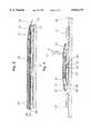
- FIG. 1is a perspective view of a wall portion of a process vessel on which sheets comprising thermoplastic polymer have been secured thereto and on which a welding means formed according to the instant invention is attached.
- FIG. 2is a front cutaway view of a wall portion and a welding means of similar form to FIG. 1.
- FIG. 3is a longitudinal cross-sectional view of the wall portion and welding means taken along line 3--3 of FIG. 2.
- FIG. 4is a cross-sectional view of the wall portion and welding means taken along line 4--4 of FIG. 2.
- FIG. 5is a plan view of a wall section depicting the entire run of a welding means along the seam, in accordance with the instant invention.
- thermoplastic polymersin sheet form
- the most common bonding processesusually involve the application of heat to edge portions of the sheets.
- heatingis accompanied by the application of pressure.
- the edge portionsare softened until they flow together under the application of pressure.
- Upon coolingthe materials solidify and the sheets are fused together.
- this processis referred to as fusion welding.
- Equipment for carrying out this processis sometimes referred to as a fusion welder.
- fluorocarbon polymersare a class of paraffinic polymers which have some or all of the hydrogen replaced by fluorine.
- fluorocarbon resinsare polytetrafluoroethylene (PTFE), fluorinated ethylene propylene copolymer (FEP), perfluoroalkoxy (PFA) resin, polychlortrifluoroethylene (PCTFE), ethylenetrichlortrifluoroethylene copolymer (ECTFE), ethylenetetrafluoroethylene copolymer (ETFE), poly(vinylidene fluoride) (PVDF), poly(vinyl fluoride) (PVF), and mixtures of one or more of these. While it is contemplated that all of the above fluorocarbon polymers, including homopolymers, copolymers, block and graft copolymers of any of the above, may be used, it is believed that PTFE will be most widely used.
- thermoplastic (and in particular fluoropolymer) materialsWhen lining a process vessel, a plurality of sheets comprising thermoplastic (and in particular fluoropolymer) materials must first be bonded to the interior walls of the vessel.
- the fluoropolymer sheetsprovide an inert and corrosion resistant barrier while the metallic shell of the vessel provides structural support. Individual sheets of fluoropolymer material may be customized or cut to the exact size and shape required to cover the entire interior surface of the vessel.
- FIG. 1A portion of an interior wall 90 of a process vessel or storage tank is shown in FIG. 1.
- First and second fluoropolymer sheets 12, 14, respectively,are positioned proximate each other so that the edge portions 13, 15 are in abutting relationship.
- the sheets 12, 14are first bonded to the metallic shell 90 by a known adhesive means having the capability of creating a permanent bond between the liner sheets and the vessel.
- a known adhesive meanshaving the capability of creating a permanent bond between the liner sheets and the vessel.
- effective adhesive meansare epoxies or elastomeric adhesives.
- the sheet materialmay have a glass or synthetic fabric laminated to the bonding face to improve the mechanical lock of the fluoropolymer material to the adhesive.
- the second sheet 14 and the remaining sheets required to cover the entire interior of the vesselare applied in a similar fashion.
- the edge portions 13, 15are brought in close proximity to each other.
- the edge portion 15is abutted directly against edge portion 13 forming an edge-to-edge interface.
- fluoropolymer filler rodsmay be used to fill in the gap between the edge portions.
- the filler rodsare made of the same material as the sheets 12, 14.
- the filler rodsare preferably PFA (perfluoroalkoxy resin).
- edge portions 13, 15 of the sheetsit may be desirable to bevel the edge portions 13, 15 of the sheets.
- a filler rodis used when the edge portions 13, 15 are beveled. Since the force applied by the welder 10 is substantially perpendicular to the plane of the sheets 12, 14, a more direct pressure is brought to bear against the edge-to-edge interface when the filler rod is forced into the space formed by the beveled edge portions thereby improving the quality of the resultant weld.
- the decision to bevel the edgesusually depends on the ability of the sheet material to flow when heated. If the material does not flow readily, it is usually desirable to bevel the edges.
- a welding meansas will be more fully described hereinafter, is generally indicated at 10.
- the welding means 10is positioned over a seam 19 formed by abutting the edge portion 15 of second sheet 14 against the edge portion 13 of first sheet 14.
- the welding means 10comprises a fusion welder as explained more fully hereafter.
- the fusion welderincludes means for applying heat and means for creating a vacuum proximate the region to be welded.
- the heat applying meanscomprises an electrically resistive heating element.
- the resistive heating elementcomprises a flexible heating ribbon 20.
- the resistive heating ribbon 20is made of metal which has a low thermal coefficient of expansion; therefore, when the heating ribbon 20 is in place, it does not move or buckle when it heats up.
- the heating ribbon 20is a metallic alloy made from approximately 64% iron and 36% nickel.
- the width and thickness of the ribbon 20must provide a sufficient watt density to melt the edge portions and may be customized for a particular application. As shown in FIGS. 2 and 4, it must be sufficiently wide to cover the "seam" or interface formed by the adjoining edge portions 13, 15 of each sheet.
- the resistive heating ribbon 20is approximately 1.905 cm and 0.0127 cm thick.
- the heating ribbon 20has a resistance of approximately 1.0 ⁇ per linear meter.
- the nickel-chromium heating tapehas a higher resistance per linear dimension allowing the welding operator to more accurately control the current flow to the heating tape thereby controlling the temperature of the heating tape.
- the fusion weldercovers the entire length of the seam.
- shorter fusion weldersmay be employed, in which case a relatively long seam must be welded in multiple steps, wherein each step begins by overlapping the previously welded area by approximately 1.27 cm and positioning the remaining portion of the fusion welder over an unwelded portion of the seam. Overlapping a portion of the previous weld reduces the chance of a defect at the weld junction.
- the means for establishing a vacuum over the seampreferably comprises an air-impermeable membrane 22.
- the membrane 22is made from a substantially non-porous flexible and collapsible material.
- a plastic materialpreferably nylon film having a thickness of about 0.005 cm, as manufactured by I.P.P. of Carson, Calif. under the trademark STRETCHLON, is used.
- the membrane 22forms an enclosure which completely encompasses the resistive ribbon 20 and the edge portions 13, 15.
- An adhesive means 31is used to releasably attach the membrane 22 to the sheets 12, 14.
- the adhesive means 31provides a hermetic seal between the four sides of the membrane and the sheets, thereby forming what is commonly referred to in the art as a vacuum bag.
- the adhesive means 31should be of the type which is easily applied, readily bonds to the membrane and the fluoropolymer material, and is easily removed.
- One suitable adhesive means 31is "High Tack Vacuum Bag Sealing Tape", as manufactured by Airtech International, Inc. under product number GS-213.
- shim stockconsisting of flexible stainless steel foil may be used instead of the nylon film to form the air impermeable membrane 22.
- closed cell self stick silicone sponge strippingis used as the adhesive means 31 to releasably attach the foil to the sheets 12, 14. The foil is placed over the heating ribbon and the silicone stripping is applied to the exterior of the foil and the sheets.
- the breather pad 24must be porous to provide a pathway for the escaping air, otherwise it may be comprised of any fabric that can thermally protect the membrane 22, from heat generated by the heating ribbon. Further, the pad 24 also prevents heat loss from the resistive ribbon 20. In this manner, less energy is needed to fuse the sheets together.
- Non-stick strips 26, 28may be interposed between the resistive ribbon 20 and the edge portions 13, 15, and between the breather insulator pad 24 and the resistive ribbon 20, respectively.
- the non-stick strips 26, 28are at least as wide as the resistive ribbon 20 and preferably have a thickness of about 0.013 cm.
- the non-stick stripsare made of polyimide as sold under the trademark Kapton®, manufactured by the E.I. du Pont de Nemours, Inc.
- Kapton®manufactured by the E.I. du Pont de Nemours, Inc.
- the resistive ribbon 20has a tendency to stick to the edge portions 13, 15 of the fluoropolymer sheets and to the breather pad 24.
- the non-stick strips 26, 28prevent the resistive ribbon 20 from sticking to these surfaces.
- non-stick strip 26has a relatively smooth surface which contributes to the smooth finish on the resulting undoctored weld.
- the non-stick strips 26, 28are an electrical insulator. Since the non-stick strips 26, 28 come in direct contact with the resistive heating ribbon 20, they electrically isolate the heating ribbon 20 from other metals (e.g., the breather pad 24 may have some metal strands to provide support; and the tank wall 90 may be exposed at certain points) preventing an electrical short circuit.
- the non-stick strips 26, 28come in direct contact with the resistive heating ribbon 20, they electrically isolate the heating ribbon 20 from other metals (e.g., the breather pad 24 may have some metal strands to provide support; and the tank wall 90 may be exposed at certain points) preventing an electrical short circuit.
- An electric current generating means 50is attached via wires 52, 54 to the ends of the resistive ribbon 20, as shown schematically in FIG. 5.
- the temperature of the ribbonbegins to rise.
- the temperature of the ribbonis directly proportional to the amount of current flowing through the ribbon, and can be accurately regulated by a microprocessor controller.
- Means for drawing and regulating a vacuumcomprises a vacuum connector 51 which communicates with the interior of membrane 22, as shown in FIGS. 4 and 5, and a heavy-wall tubing (not shown).
- a vacuum connector 51 which may be used with a plastic vacuum bagis Vac Valve 409 SS HTR, manufactured by Airtech International, Inc. of Carson, Calif.
- the vacuum meansserves the purpose of evacuating the air from the interior of the membrane 22, establishing a negative pressure with respect to atmospheric pressure.
- the ambient atmospheric pressureis applied to the outer surface of the membrane 22 thereby causing the membrane 22 to collapse and applying a substantially uniform force against the resistive ribbon 20.
- the breather fabric 24allows free passage of the air from within the membrane 22 and ensures the elimination of all bubbles within the system. (Air bubbles can balance the atmosphere pressure thereby preventing a uniform pressure along the entire length of the seam.)
- the force generated by the atmospheric pressure against the membrane 22is in a direction substantially normal to the top surface of the resistive ribbon 20 insuring that the ribbon 20 remains uniformly and firmly pressed against the seam 19.
- thermoplasticin particular, fluoropolymer
- a sheet of fluoropolymer materialis selected to be used as a "standard” sheet. Therefore, many of the seams will have the same length.
- An advantage of using "standard" size fluoropolymer sheetsis that one air-impermeable membrane and one resistive ribbon can be used and re-used to weld a majority of the seams of abutting fluoropolymer sheets.
- the sheetsare preferably selected and arranged in such a manner as to minimize the number of seams. Since the "standard" sheet may be four feet by eleven feet in dimension, it will not be unusual to weld an eleven-foot seam.
- a sketch of how the sheets will be fitted to the interior of the vesselmay be drawn.
- any irregularitiese.g., nozzles
- the standard sheetmay be cut to accommodate such variations at a remote location.
- the sheetsare transported to the site of the process vessel.
- the interior of the vesselis cleaned and prepared for application of the adhesive means.
- the adhesivemay be applied either to the vessel or to the bonding surface of the fluoropolymer sheets.
- the edge portions 13, 15should be cleaned. If needed, a filler rod may be added at this time.
- the elements comprising the fusion welder 10are placed over the seam in the following order: The first non-stick strip 26; the electrically resistive heating ribbon 20; the second non-stick strip 28, the breather fabric 24 and the membrane 22.
- a heat-resistant tape 44, 46may be used, as needed, to secure the elements of the welder against the sheets 12, 14.
- the preferred tapeis Kapton® having a self-sticking adhesive side such as AirKap 1 manufactured by Airtech International.
- the non-stick strip 26 and the resistive ribbon 20are at least as long as the length of the desired weld, and are preferably as long as an entire seam.
- the tape strip 44may be applied at intervals as needed to secure the strip 28 and the resistive ribbon 20 against the fluoropolymer sheets 12, 14.
- the second non-stick strip 28 and the breather/insulator pad 24are placed over the resistive ribbon 20.
- a second tape strip 46may be used to secure the non-stick strip 26 and pad 24. Tape 46 may be the same material as used for tape 44.
- the illustrative embodimentutilizes the breather/insulator pad 24 and the non-stick insulating strips 26, 28 to sandwich the resistive heating ribbon 20. It is understood by one skilled in the art that there may be applications in which the breather/insulator pad 24 and/or one or more of the non-stick strips 26, 28 may be omitted.
- the resistive ribbon 20 with non-stick strips 26, 28 and/or pad 24may be pre-formed and rolled-up as one unit. It may even be desirable to cut the elements to a desired length before they are rolled up. The roll is easily transported to the installation site. This will decrease the time needed to attach the component parts of the welder 10 over the seam 19.
- the periphery of the air-impermeable membrane 22is hermetically sealed to the fluoropolymer sheets.
- the sealed membrane 22forms the vacuum bag which encloses the heating ribbon 20 and the edges 13, 15 to be welded together. Air is also trapped inside of the vacuum bag.
- the current generating means 50is electrically connected to the ends of the resistive ribbon 20.
- wire leads 52, 54are attached to each end of the resistive ribbon 20, and are fed under the air-impermeable membrane 22.
- the wire leads 52, 54may go through the bag. Regardless of how the leads are positioned, it should be noted that the air-impermeable membrane 22 must be sealed against the leads 21 to ensure that the vacuum bag remains air-impermeable.
- the vacuum meansfurther comprises a vacuum connector 51 which communicates with the interior of the air-impermeable flexible membrane 22.
- the vacuum meansis activatable to thereby remove the air from inside the sealed flexible membrane 22. Atmospheric pressure compresses the flexible membrane 22 against the resistive ribbon 20, which in turn is compressed against the surfaces contiguous to edge portions 13, 15 of the fluoropolymer sheets.
- the evacuated vacuum bagprovides a simple and effective low vacuum-pressure means for the application of a uniform force along the entire run of the resistive ribbon 20.
- the force created by ambient atmospheric pressure against the membrane 22ensures that the resistive ribbon 20 remains flat and uniformly pressed against the seam 19 thereby increasing the uniformity of the pressure and temperature at all points along the seam in a simple, but highly effective manner.
- the current producing meansis activated thereby heating the resistive ribbon 20.
- the currentis applied to the resistive ribbon 20 until the edge portions 13, 15 become molten.
- the vacuum meansremains activated until the molten fluoropolymer material cools and solidifies.
- the releasable adhesive means attaching the flexible membrane 22is removed.
- the breather/insulator pad 24 and the resistive ribbon sandwichare also removed. In the manner described, the edge portions 13, 15 are joined, thereby forming a contiguous, non-porous, uniform joint having substantially the characteristics of the virgin material.
- the resulting weldhas a weld efficiency of at least 50% of virgin elongation and at least 80% of tensile strength of the virgin material as measured using the ASTM 638 standard.
- the undoctored weld surfacedoes not extend beyond about 0.2 cm from the plane defined by the top surfaces of said sheets resulting in a relatively smooth weld that reduces the accumulation of the contaminants.
- the undoctored finish of a weldi.e., the appearance of the weld without any sanding, shaping, machining, buffing, etc.
- the undoctored finish of welds made by other techniquesit contains no flaws. (Flaws are defined as defects in the weld that will not withstand an imposed 20,000 volt DC "spark test" in accordance with the standards set by the Society of Plastics Industry.)
Landscapes
- Engineering & Computer Science (AREA)
- Mechanical Engineering (AREA)
- Physics & Mathematics (AREA)
- Thermal Sciences (AREA)
- Textile Engineering (AREA)
- Fluid Mechanics (AREA)
- Lining Or Joining Of Plastics Or The Like (AREA)
Abstract
Description
Claims (18)
Priority Applications (2)
| Application Number | Priority Date | Filing Date | Title |
|---|---|---|---|
| US08/480,799US5814175A (en) | 1995-06-07 | 1995-06-07 | Welded thermoplastic polymer article and a method and apparatus for making same |
| GB9611622AGB2301796B (en) | 1995-06-07 | 1996-06-04 | Welded thermoplastic article and method of making same |
Applications Claiming Priority (1)
| Application Number | Priority Date | Filing Date | Title |
|---|---|---|---|
| US08/480,799US5814175A (en) | 1995-06-07 | 1995-06-07 | Welded thermoplastic polymer article and a method and apparatus for making same |
Publications (1)
| Publication Number | Publication Date |
|---|---|
| US5814175Atrue US5814175A (en) | 1998-09-29 |
Family
ID=23909413
Family Applications (1)
| Application Number | Title | Priority Date | Filing Date |
|---|---|---|---|
| US08/480,799Expired - LifetimeUS5814175A (en) | 1995-06-07 | 1995-06-07 | Welded thermoplastic polymer article and a method and apparatus for making same |
Country Status (2)
| Country | Link |
|---|---|
| US (1) | US5814175A (en) |
| GB (1) | GB2301796B (en) |
Cited By (29)
| Publication number | Priority date | Publication date | Assignee | Title |
|---|---|---|---|---|
| US6276532B1 (en) | 2000-03-15 | 2001-08-21 | Sealed Air Corporation (Us) | Inflatable packaging cushion with a resistance wire |
| US6289912B1 (en)* | 1998-07-10 | 2001-09-18 | Fluoroware, Inc. | Pinch element plastic valve |
| US6569283B1 (en) | 2000-03-15 | 2003-05-27 | Sealed Air Corporation (Us) | Inflator/sealer device for inflatable packaging cushion |
| US20030221783A1 (en)* | 2000-05-10 | 2003-12-04 | Swagelok Company | Ir welding of fluoropolymers |
| US20050016993A1 (en)* | 2003-04-17 | 2005-01-27 | Koskey James Donald | Heated pet mat |
| US6991449B1 (en)* | 2003-04-11 | 2006-01-31 | Northrop Grumman Corporation | Heating apparatus for in-situ de-bulking composite parts during layup |
| US20060191909A1 (en)* | 2005-02-11 | 2006-08-31 | Patrick Powell | Method of welding a component inside a hollow vessel |
| NL1030029C2 (en)* | 2005-09-26 | 2007-03-27 | Gtm Consulting B V | Method and device for gluing components to a composite molded part. |
| US20070151670A1 (en)* | 2003-12-01 | 2007-07-05 | Fuji Electric Holding Co., Ltd | Vacuum lamination device |
| US20070259149A1 (en)* | 2002-11-13 | 2007-11-08 | Ward-Kraft, Inc. | Form having abutting tape-interconnected substrates and method of making same |
| US20080068590A1 (en)* | 2004-03-11 | 2008-03-20 | Eads Construcciones Aeronatuicas, S.A. | Method for the certification of heater blankets by means of infrared thermography |
| US20080245471A1 (en)* | 2007-04-05 | 2008-10-09 | Curtis Goad | Method and apparatus for lining process tanks |
| US20090151852A1 (en)* | 2005-09-29 | 2009-06-18 | Roebroeks Geerardus Hubertus J | Method for producing a molding made of a composite material |
| US20090166346A1 (en)* | 2006-01-11 | 2009-07-02 | Udo Ketelhut | Method and Device for Producing a Bond of Components |
| US20090211697A1 (en)* | 2007-05-15 | 2009-08-27 | Heinimann Markus B | Reinforced hybrid structures and methods thereof |
| US20100043939A1 (en)* | 2006-05-15 | 2010-02-25 | Alcoa, Inc. | Reinforced Hybrid Structures and Methods Thereof |
| US20100133380A1 (en)* | 2006-09-12 | 2010-06-03 | Roebroeks Geerardus Hubertus J | Skin panel for an aircraft fuselage |
| US20100266867A1 (en)* | 2006-06-13 | 2010-10-21 | Geerardus Hubertus Joannes Jozeph Roebroeks | Laminate of metal sheets and polymer |
| US20110139334A1 (en)* | 2004-03-26 | 2011-06-16 | Tadahiro Ohmi | Bonding method and resin member bonded thereby |
| US20120148805A1 (en)* | 2007-04-05 | 2012-06-14 | Curtis Goad | Methods and Apparatus for Lining Process Tanks |
| US20140030093A1 (en)* | 2011-04-11 | 2014-01-30 | Martin Dahl | Wind turbine blade comprising resistive heating means |
| US8955711B2 (en) | 2012-03-22 | 2015-02-17 | Curtis Goad | Liners and linings for tanks |
| US9759380B2 (en) | 2012-03-22 | 2017-09-12 | Curtis Goad | Liners and linings for tanks and other liquid containment vessels |
| US20170369236A1 (en)* | 2007-04-05 | 2017-12-28 | Curtis Goad | Liners including corner reinforcement and methods and apparatus for providing additional protection and/or reinforcement at the corners of a liner |
| US10138053B2 (en) | 2007-04-05 | 2018-11-27 | Curtis Goad | Methods and apparatus for lining process tanks |
| US10189218B2 (en)* | 2016-04-19 | 2019-01-29 | The Boeing Company | Thermal composite material repair utilizing vacuum compression |
| US10392186B2 (en) | 2012-03-22 | 2019-08-27 | Curtis Goad | Liners and linings for tanks and other liquid containment vessels |
| US11376783B2 (en) | 2018-10-31 | 2022-07-05 | Curtis Goad | Corner profiles and/or corner reinforcement for liners and linings suitable for use with tanks and other storage/containment vessels |
| US11396125B2 (en) | 2019-04-19 | 2022-07-26 | Goad Company | Liners and methods of making liners |
Families Citing this family (2)
| Publication number | Priority date | Publication date | Assignee | Title |
|---|---|---|---|---|
| DE102006007027A1 (en) | 2006-02-15 | 2007-10-18 | Airbus Deutschland Gmbh | Locomotion unit`s e.g. aircraft, double walled floor segment for interior space separation, has connection element, and hollow space generated by separation element and to accommodate freshwater pump and control unit |
| JP4990261B2 (en) | 2008-12-25 | 2012-08-01 | 日東電工株式会社 | Sheet member joining method |
Citations (33)
| Publication number | Priority date | Publication date | Assignee | Title |
|---|---|---|---|---|
| US2713017A (en)* | 1954-07-12 | 1955-07-12 | Connecticut Hard Rubber Co | Welding plastic film sections |
| US2802086A (en)* | 1955-10-04 | 1957-08-06 | Nicholas Langer | Sealing device for heat sealing machines of the thermal impulse type |
| US3207644A (en)* | 1959-07-20 | 1965-09-21 | Garlock Inc | Method of making a fluorocarbon resin jacketed gasket |
| US3660210A (en)* | 1969-05-13 | 1972-05-02 | Harry Samuel Chapman | Static autogenous sealing bar |
| US3677845A (en)* | 1970-07-24 | 1972-07-18 | Fluorodynamics Inc | Method for the in situ covering of large diameter process rolls with heat shrinkable films of fluorinated ethylene polymers and the like |
| US3707428A (en)* | 1970-07-24 | 1972-12-26 | Fluorodynamics Inc | Sealing apparatus for manufacturing roller coverings,vessel liners and the like |
| US3826702A (en)* | 1969-05-13 | 1974-07-30 | H Chapman | Method of in-situ heat seal sleeving for large rolls |
| US3837965A (en)* | 1972-10-17 | 1974-09-24 | Us Air Force | Portable repair apparatus |
| US3927233A (en)* | 1974-01-25 | 1975-12-16 | Raychem Corp | Welded polymeric articles and process |
| US3951724A (en)* | 1972-12-04 | 1976-04-20 | Seal Incorporated | Vacuum press |
| US4283448A (en)* | 1980-02-14 | 1981-08-11 | W. L. Gore & Associates, Inc. | Composite polytetrafluoroethylene article and a process for making the same |
| US4352707A (en)* | 1981-04-23 | 1982-10-05 | Grumman Aerospace Corporation | Composite repair apparatus |
| US4390384A (en)* | 1977-12-20 | 1983-06-28 | Hardigg Industries, Inc. | Method and apparatus for bonding thermoplastic materials |
| US4541883A (en)* | 1984-06-13 | 1985-09-17 | Dayco Corporation | Method of splicing a thermoplastic mandrel and a mandrel made by said method |
| US4560428A (en)* | 1984-08-20 | 1985-12-24 | Rockwell International Corporation | System and method for producing cured composites |
| USRE32103E (en)* | 1981-03-13 | 1986-04-01 | Gundle Holdings Limited | Welding of plastics material |
| US4622091A (en)* | 1984-11-29 | 1986-11-11 | The Boeing Company | Resin film infusion process and apparatus |
| US4681651A (en)* | 1986-08-07 | 1987-07-21 | Lockheed Corporation | Vacuum bag sealing system |
| US4701291A (en)* | 1986-07-25 | 1987-10-20 | The Duriron Company, Inc. | Process of isostatic molding and bonding fluoropolymers |
| US4725393A (en)* | 1985-10-07 | 1988-02-16 | Kabushiki Kaisha Kawakami Seisakusho | Method for vacuum compression of laminated sheet material |
| US4732639A (en)* | 1985-08-30 | 1988-03-22 | Newsom Cosby M | Vacuum bagging apparatus |
| US4876041A (en)* | 1986-10-14 | 1989-10-24 | Georg Fischer Ag | Method for fusion joining plastic pipe |
| US4886442A (en)* | 1988-05-26 | 1989-12-12 | The Boeing Company | Vacuum bag tooling apparatus with inflatable seal |
| US4927999A (en)* | 1986-10-14 | 1990-05-22 | Georg Fischer Ag | Apparatus for fusion joining plastic pipe |
| US4929293A (en)* | 1984-07-09 | 1990-05-29 | Fluoroware, Inc. | Welding fluoropolymer pipe and fittings |
| US4978408A (en)* | 1985-11-04 | 1990-12-18 | Forward Technology Industries, Inc. | Method for heat sealing thermoplastic articles |
| US4990296A (en)* | 1989-08-21 | 1991-02-05 | Garlock Inc. | Welding of filled sintered polytetrafluoroethylene |
| US5039371A (en)* | 1989-03-23 | 1991-08-13 | Lockheed Corporation | Apparatus for roll-consolidation of thermoplastic composite laminates |
| US5116216A (en)* | 1991-02-28 | 1992-05-26 | The United States Of America As Represented By The Secretary Of The Navy | Apparatus for preparing thermoplastic composites |
| US5123985A (en)* | 1986-09-02 | 1992-06-23 | Patricia Evans | Vacuum bagging apparatus and method including a thermoplastic elastomer film vacuum bag |
| US5196079A (en)* | 1991-01-18 | 1993-03-23 | Branson Ultrasonics Corporation | Method and apparatus for joining thermoplastic workpieces by high frequency vibrations |
| US5261993A (en)* | 1992-06-08 | 1993-11-16 | Airtech International Inc. | Means for bonding shaped parts of composites or other materials |
| US5322665A (en)* | 1992-04-15 | 1994-06-21 | The Charles Stark Draper Laboratories, Inc. | Disposable self contained cartridge or resin transfer molding and resin transfer molding method |
Family Cites Families (1)
| Publication number | Priority date | Publication date | Assignee | Title |
|---|---|---|---|---|
| EP0263980A3 (en)* | 1986-10-14 | 1990-01-31 | Georg Fischer Aktiengesellschaft | Apparatus and method for fusion joining plastic pipe |
- 1995
- 1995-06-07USUS08/480,799patent/US5814175A/ennot_activeExpired - Lifetime
- 1996
- 1996-06-04GBGB9611622Apatent/GB2301796B/ennot_activeExpired - Fee Related
Patent Citations (33)
| Publication number | Priority date | Publication date | Assignee | Title |
|---|---|---|---|---|
| US2713017A (en)* | 1954-07-12 | 1955-07-12 | Connecticut Hard Rubber Co | Welding plastic film sections |
| US2802086A (en)* | 1955-10-04 | 1957-08-06 | Nicholas Langer | Sealing device for heat sealing machines of the thermal impulse type |
| US3207644A (en)* | 1959-07-20 | 1965-09-21 | Garlock Inc | Method of making a fluorocarbon resin jacketed gasket |
| US3826702A (en)* | 1969-05-13 | 1974-07-30 | H Chapman | Method of in-situ heat seal sleeving for large rolls |
| US3660210A (en)* | 1969-05-13 | 1972-05-02 | Harry Samuel Chapman | Static autogenous sealing bar |
| US3677845A (en)* | 1970-07-24 | 1972-07-18 | Fluorodynamics Inc | Method for the in situ covering of large diameter process rolls with heat shrinkable films of fluorinated ethylene polymers and the like |
| US3707428A (en)* | 1970-07-24 | 1972-12-26 | Fluorodynamics Inc | Sealing apparatus for manufacturing roller coverings,vessel liners and the like |
| US3837965A (en)* | 1972-10-17 | 1974-09-24 | Us Air Force | Portable repair apparatus |
| US3951724A (en)* | 1972-12-04 | 1976-04-20 | Seal Incorporated | Vacuum press |
| US3927233A (en)* | 1974-01-25 | 1975-12-16 | Raychem Corp | Welded polymeric articles and process |
| US4390384A (en)* | 1977-12-20 | 1983-06-28 | Hardigg Industries, Inc. | Method and apparatus for bonding thermoplastic materials |
| US4283448A (en)* | 1980-02-14 | 1981-08-11 | W. L. Gore & Associates, Inc. | Composite polytetrafluoroethylene article and a process for making the same |
| USRE32103E (en)* | 1981-03-13 | 1986-04-01 | Gundle Holdings Limited | Welding of plastics material |
| US4352707A (en)* | 1981-04-23 | 1982-10-05 | Grumman Aerospace Corporation | Composite repair apparatus |
| US4541883A (en)* | 1984-06-13 | 1985-09-17 | Dayco Corporation | Method of splicing a thermoplastic mandrel and a mandrel made by said method |
| US4929293A (en)* | 1984-07-09 | 1990-05-29 | Fluoroware, Inc. | Welding fluoropolymer pipe and fittings |
| US4560428A (en)* | 1984-08-20 | 1985-12-24 | Rockwell International Corporation | System and method for producing cured composites |
| US4622091A (en)* | 1984-11-29 | 1986-11-11 | The Boeing Company | Resin film infusion process and apparatus |
| US4732639A (en)* | 1985-08-30 | 1988-03-22 | Newsom Cosby M | Vacuum bagging apparatus |
| US4725393A (en)* | 1985-10-07 | 1988-02-16 | Kabushiki Kaisha Kawakami Seisakusho | Method for vacuum compression of laminated sheet material |
| US4978408A (en)* | 1985-11-04 | 1990-12-18 | Forward Technology Industries, Inc. | Method for heat sealing thermoplastic articles |
| US4701291A (en)* | 1986-07-25 | 1987-10-20 | The Duriron Company, Inc. | Process of isostatic molding and bonding fluoropolymers |
| US4681651A (en)* | 1986-08-07 | 1987-07-21 | Lockheed Corporation | Vacuum bag sealing system |
| US5123985A (en)* | 1986-09-02 | 1992-06-23 | Patricia Evans | Vacuum bagging apparatus and method including a thermoplastic elastomer film vacuum bag |
| US4876041A (en)* | 1986-10-14 | 1989-10-24 | Georg Fischer Ag | Method for fusion joining plastic pipe |
| US4927999A (en)* | 1986-10-14 | 1990-05-22 | Georg Fischer Ag | Apparatus for fusion joining plastic pipe |
| US4886442A (en)* | 1988-05-26 | 1989-12-12 | The Boeing Company | Vacuum bag tooling apparatus with inflatable seal |
| US5039371A (en)* | 1989-03-23 | 1991-08-13 | Lockheed Corporation | Apparatus for roll-consolidation of thermoplastic composite laminates |
| US4990296A (en)* | 1989-08-21 | 1991-02-05 | Garlock Inc. | Welding of filled sintered polytetrafluoroethylene |
| US5196079A (en)* | 1991-01-18 | 1993-03-23 | Branson Ultrasonics Corporation | Method and apparatus for joining thermoplastic workpieces by high frequency vibrations |
| US5116216A (en)* | 1991-02-28 | 1992-05-26 | The United States Of America As Represented By The Secretary Of The Navy | Apparatus for preparing thermoplastic composites |
| US5322665A (en)* | 1992-04-15 | 1994-06-21 | The Charles Stark Draper Laboratories, Inc. | Disposable self contained cartridge or resin transfer molding and resin transfer molding method |
| US5261993A (en)* | 1992-06-08 | 1993-11-16 | Airtech International Inc. | Means for bonding shaped parts of composites or other materials |
Cited By (42)
| Publication number | Priority date | Publication date | Assignee | Title |
|---|---|---|---|---|
| US6289912B1 (en)* | 1998-07-10 | 2001-09-18 | Fluoroware, Inc. | Pinch element plastic valve |
| US7048025B2 (en) | 2000-03-15 | 2006-05-23 | Sealed Air Corporation (Us) | Inflator/sealer device for inflatable packaging cushion |
| US6569283B1 (en) | 2000-03-15 | 2003-05-27 | Sealed Air Corporation (Us) | Inflator/sealer device for inflatable packaging cushion |
| US20030205026A1 (en)* | 2000-03-15 | 2003-11-06 | Sperry Charles R. | Inflator/sealer device for inflatable packaging cushion |
| US6276532B1 (en) | 2000-03-15 | 2001-08-21 | Sealed Air Corporation (Us) | Inflatable packaging cushion with a resistance wire |
| US20030221783A1 (en)* | 2000-05-10 | 2003-12-04 | Swagelok Company | Ir welding of fluoropolymers |
| US20070259149A1 (en)* | 2002-11-13 | 2007-11-08 | Ward-Kraft, Inc. | Form having abutting tape-interconnected substrates and method of making same |
| US7618034B2 (en)* | 2002-11-13 | 2009-11-17 | Ward-Kraft, Inc. | Form having abutting tape-interconnected substrates and method of making same |
| US6991449B1 (en)* | 2003-04-11 | 2006-01-31 | Northrop Grumman Corporation | Heating apparatus for in-situ de-bulking composite parts during layup |
| US20050016993A1 (en)* | 2003-04-17 | 2005-01-27 | Koskey James Donald | Heated pet mat |
| US7755007B2 (en)* | 2003-04-17 | 2010-07-13 | K&H Manufacturing, Inc | Heated pet mat |
| US8408263B2 (en)* | 2003-12-01 | 2013-04-02 | Fuji Electric Holding Co., Ltd. | Vacuum lamination device |
| US20070151670A1 (en)* | 2003-12-01 | 2007-07-05 | Fuji Electric Holding Co., Ltd | Vacuum lamination device |
| US7568833B2 (en)* | 2004-03-11 | 2009-08-04 | Eads Construcciones Aeronauticas, S,A, | Method for the certification of heater blankets by means of infrared thermography |
| US20080068590A1 (en)* | 2004-03-11 | 2008-03-20 | Eads Construcciones Aeronatuicas, S.A. | Method for the certification of heater blankets by means of infrared thermography |
| US20110139334A1 (en)* | 2004-03-26 | 2011-06-16 | Tadahiro Ohmi | Bonding method and resin member bonded thereby |
| US20060191909A1 (en)* | 2005-02-11 | 2006-08-31 | Patrick Powell | Method of welding a component inside a hollow vessel |
| US7378624B2 (en) | 2005-02-11 | 2008-05-27 | Denso International America, Inc. | Method of welding a component inside a hollow vessel |
| WO2007035100A3 (en)* | 2005-09-26 | 2007-05-10 | Alcoa Inc | Method and device for adhering components to a composite molding |
| NL1030029C2 (en)* | 2005-09-26 | 2007-03-27 | Gtm Consulting B V | Method and device for gluing components to a composite molded part. |
| US20080277049A1 (en)* | 2005-09-26 | 2008-11-13 | Roebroeks Geerardus Hubertus J | Method and Device for Adhering Components to a Composite Molding |
| US20090151852A1 (en)* | 2005-09-29 | 2009-06-18 | Roebroeks Geerardus Hubertus J | Method for producing a molding made of a composite material |
| US20090166346A1 (en)* | 2006-01-11 | 2009-07-02 | Udo Ketelhut | Method and Device for Producing a Bond of Components |
| US20100043939A1 (en)* | 2006-05-15 | 2010-02-25 | Alcoa, Inc. | Reinforced Hybrid Structures and Methods Thereof |
| US20100266867A1 (en)* | 2006-06-13 | 2010-10-21 | Geerardus Hubertus Joannes Jozeph Roebroeks | Laminate of metal sheets and polymer |
| US7955713B2 (en) | 2006-06-13 | 2011-06-07 | Alcoa Inc. | Laminate of metal sheets and polymer |
| US20100133380A1 (en)* | 2006-09-12 | 2010-06-03 | Roebroeks Geerardus Hubertus J | Skin panel for an aircraft fuselage |
| US20120148805A1 (en)* | 2007-04-05 | 2012-06-14 | Curtis Goad | Methods and Apparatus for Lining Process Tanks |
| US20170369236A1 (en)* | 2007-04-05 | 2017-12-28 | Curtis Goad | Liners including corner reinforcement and methods and apparatus for providing additional protection and/or reinforcement at the corners of a liner |
| US20080245471A1 (en)* | 2007-04-05 | 2008-10-09 | Curtis Goad | Method and apparatus for lining process tanks |
| US8133345B2 (en)* | 2007-04-05 | 2012-03-13 | Curtis Goad | Method and apparatus for lining process tanks |
| US10138053B2 (en) | 2007-04-05 | 2018-11-27 | Curtis Goad | Methods and apparatus for lining process tanks |
| US9278478B2 (en)* | 2007-04-05 | 2016-03-08 | Curtis Goad | Methods and apparatus for lining process tanks |
| US20090211697A1 (en)* | 2007-05-15 | 2009-08-27 | Heinimann Markus B | Reinforced hybrid structures and methods thereof |
| US20140030093A1 (en)* | 2011-04-11 | 2014-01-30 | Martin Dahl | Wind turbine blade comprising resistive heating means |
| US9719359B2 (en)* | 2011-04-11 | 2017-08-01 | LM WP Patent Holdings A/S | Wind turbine blade comprising resistive heating means |
| US9759380B2 (en) | 2012-03-22 | 2017-09-12 | Curtis Goad | Liners and linings for tanks and other liquid containment vessels |
| US8955711B2 (en) | 2012-03-22 | 2015-02-17 | Curtis Goad | Liners and linings for tanks |
| US10392186B2 (en) | 2012-03-22 | 2019-08-27 | Curtis Goad | Liners and linings for tanks and other liquid containment vessels |
| US10189218B2 (en)* | 2016-04-19 | 2019-01-29 | The Boeing Company | Thermal composite material repair utilizing vacuum compression |
| US11376783B2 (en) | 2018-10-31 | 2022-07-05 | Curtis Goad | Corner profiles and/or corner reinforcement for liners and linings suitable for use with tanks and other storage/containment vessels |
| US11396125B2 (en) | 2019-04-19 | 2022-07-26 | Goad Company | Liners and methods of making liners |
Also Published As
| Publication number | Publication date |
|---|---|
| GB2301796B (en) | 1998-12-23 |
| GB2301796A (en) | 1996-12-18 |
| GB9611622D0 (en) | 1996-08-07 |
Similar Documents
| Publication | Publication Date | Title |
|---|---|---|
| US5814175A (en) | Welded thermoplastic polymer article and a method and apparatus for making same | |
| Troughton | Handbook of plastics joining: a practical guide | |
| JP3793536B2 (en) | Method of forming a welded joint and the joint | |
| US3891490A (en) | Welded polymeric articles and process | |
| EP0281347B1 (en) | Bonding thermoplastic layers | |
| US6884976B2 (en) | Induction heating for localized joining of structural members | |
| US3927233A (en) | Welded polymeric articles and process | |
| US6228204B1 (en) | Method and apparatus for welding together fluoropolymer pipe liners | |
| MXPA06002306A (en) | Method of combining welding and adhesive bonding for joining metal components. | |
| US4990296A (en) | Welding of filled sintered polytetrafluoroethylene | |
| EP0175432B1 (en) | All fluorocarbon filter element | |
| EP4289606A1 (en) | Semi-conformable pressure application system and method for joining composite parts | |
| GB2224683A (en) | Connection element for producing a welded and glued connection | |
| JPS6056611B2 (en) | Method for joining molded bodies made of polytetrafluoroethylene | |
| GB2056907A (en) | Apparatus for welding thermoplastic layers | |
| JPS6235868B2 (en) | ||
| JPS62288029A (en) | Vessel made of resin and bonded by fusion, and fusion bonding thereof | |
| JP4106287B2 (en) | Method for joining heat-fusible tubular bodies | |
| JP4602114B2 (en) | Waterproof sheet fixing method and pressure jig | |
| EP0445997A1 (en) | Method of making composite structure for superplastic forming | |
| JP3373028B2 (en) | Resin sheet bonding equipment | |
| JP3705789B2 (en) | Method for processing step difference in joint end of membrane material | |
| JPH06226854A (en) | Welding of plastic pipes | |
| JP2587939B2 (en) | Lining method of sheet containing polytetrafluoroethylene | |
| Barbari et al. | Weldability of Dissimilar HDPE Pipe Materials for Heated Tool Butt-Welding |
Legal Events
| Date | Code | Title | Description |
|---|---|---|---|
| AS | Assignment | Owner name:EDLON PRODUCTS, INC., PENNSYLVANIA Free format text:ASSIGNMENT OF ASSIGNORS INTEREST;ASSIGNORS:RAU, STEVEN E.;MORRIS, BRIAN C.;SAUER, ROBERT W.;REEL/FRAME:007720/0633 Effective date:19951103 | |
| STCF | Information on status: patent grant | Free format text:PATENTED CASE | |
| FPAY | Fee payment | Year of fee payment:4 | |
| AS | Assignment | Owner name:EDLON INC., PENNSYLVANIA Free format text:CHANGE OF NAME;ASSIGNOR:EDLON PRODUCTS, INC.;REEL/FRAME:016987/0449 Effective date:19941003 | |
| FPAY | Fee payment | Year of fee payment:8 | |
| AS | Assignment | Owner name:J.P. MORGAN TRUST COMPANY, N.A., AS AGENT, ILLINOI Free format text:SECURITY INTEREST;ASSIGNOR:EDLON, INC.;REEL/FRAME:017480/0575 Effective date:20051223 | |
| AS | Assignment | Owner name:EDLON, INC., PENNSYLVANIA Free format text:PATENT RELEASE OF SECURITY INTEREST;ASSIGNOR:BANK OF NEW YORK TRUST COMPANY, N.A., AS SUCCESSOR TO J.P. MORGAN TRUST COMPANY, AS AGENT, THE;REEL/FRAME:018866/0256 Effective date:20061219 | |
| FPAY | Fee payment | Year of fee payment:12 | |
| AS | Assignment | Owner name:COMMERZBANK INTERNATIONAL S.A., LUXEMBOURG Free format text:IP SECURITY AGREEMENT SUPPLEMENT;ASSIGNOR:EDLON INC.;REEL/FRAME:034993/0651 Effective date:20150212 | |
| AS | Assignment | Owner name:EDLON INC., PENNSYLVANIA Free format text:RELEASE BY SECURED PARTY;ASSIGNOR:COMMERZBANK FINANCE & COVERED BOND S.A.;REEL/FRAME:050119/0530 Effective date:20190813 |