US5814046A - Pedicular screw and posterior spinal instrumentation - Google Patents
Pedicular screw and posterior spinal instrumentationDownload PDFInfo
- Publication number
- US5814046A US5814046AUS08/436,192US43619295AUS5814046AUS 5814046 AUS5814046 AUS 5814046AUS 43619295 AUS43619295 AUS 43619295AUS 5814046 AUS5814046 AUS 5814046A
- Authority
- US
- United States
- Prior art keywords
- screw
- pedicular
- thread
- rod
- region
- Prior art date
- Legal status (The legal status is an assumption and is not a legal conclusion. Google has not performed a legal analysis and makes no representation as to the accuracy of the status listed.)
- Expired - Lifetime
Links
- 230000035515penetrationEffects0.000claimsabstractdescription9
- 238000003780insertionMethods0.000claimsdescription4
- 230000037431insertionEffects0.000claimsdescription4
- 208000007103SpondylolisthesisDiseases0.000description13
- 238000006073displacement reactionMethods0.000description4
- 238000001356surgical procedureMethods0.000description4
- 238000012937correctionMethods0.000description3
- 238000004519manufacturing processMethods0.000description3
- 230000002093peripheral effectEffects0.000description3
- 208000031481Pathologic ConstrictionDiseases0.000description2
- 238000004873anchoringMethods0.000description2
- 230000006837decompressionEffects0.000description2
- 230000000694effectsEffects0.000description2
- 230000004927fusionEffects0.000description2
- 206010017076FractureDiseases0.000description1
- 208000002607PseudarthrosisDiseases0.000description1
- 208000008765SciaticaDiseases0.000description1
- 238000013459approachMethods0.000description1
- 230000002146bilateral effectEffects0.000description1
- 210000003164cauda equinaAnatomy0.000description1
- 230000006835compressionEffects0.000description1
- 238000007906compressionMethods0.000description1
- 230000001054cortical effectEffects0.000description1
- 230000009089cytolysisEffects0.000description1
- 230000003412degenerative effectEffects0.000description1
- 238000002513implantationMethods0.000description1
- 238000002684laminectomyMethods0.000description1
- 230000003902lesionEffects0.000description1
- 239000002184metalSubstances0.000description1
- 229910052751metalInorganic materials0.000description1
- 238000012986modificationMethods0.000description1
- 230000004048modificationEffects0.000description1
- 210000005036nerveAnatomy0.000description1
- 230000000399orthopedic effectEffects0.000description1
- 230000001575pathological effectEffects0.000description1
- 230000002787reinforcementEffects0.000description1
- 230000003014reinforcing effectEffects0.000description1
- 230000036262stenosisEffects0.000description1
- 208000037804stenosisDiseases0.000description1
- 238000005728strengtheningMethods0.000description1
- 238000013519translationMethods0.000description1
- 230000000472traumatic effectEffects0.000description1
- 230000000007visual effectEffects0.000description1
Images


Classifications
- A—HUMAN NECESSITIES
- A61—MEDICAL OR VETERINARY SCIENCE; HYGIENE
- A61B—DIAGNOSIS; SURGERY; IDENTIFICATION
- A61B17/00—Surgical instruments, devices or methods
- A61B17/56—Surgical instruments or methods for treatment of bones or joints; Devices specially adapted therefor
- A61B17/58—Surgical instruments or methods for treatment of bones or joints; Devices specially adapted therefor for osteosynthesis, e.g. bone plates, screws or setting implements
- A61B17/68—Internal fixation devices, including fasteners and spinal fixators, even if a part thereof projects from the skin
- A61B17/70—Spinal positioners or stabilisers, e.g. stabilisers comprising fluid filler in an implant
- A61B17/7074—Tools specially adapted for spinal fixation operations other than for bone removal or filler handling
- A61B17/7076—Tools specially adapted for spinal fixation operations other than for bone removal or filler handling for driving, positioning or assembling spinal clamps or bone anchors specially adapted for spinal fixation
- A61B17/7082—Tools specially adapted for spinal fixation operations other than for bone removal or filler handling for driving, positioning or assembling spinal clamps or bone anchors specially adapted for spinal fixation for driving, i.e. rotating, screws or screw parts specially adapted for spinal fixation, e.g. for driving polyaxial or tulip-headed screws
- A—HUMAN NECESSITIES
- A61—MEDICAL OR VETERINARY SCIENCE; HYGIENE
- A61B—DIAGNOSIS; SURGERY; IDENTIFICATION
- A61B17/00—Surgical instruments, devices or methods
- A61B17/56—Surgical instruments or methods for treatment of bones or joints; Devices specially adapted therefor
- A61B17/58—Surgical instruments or methods for treatment of bones or joints; Devices specially adapted therefor for osteosynthesis, e.g. bone plates, screws or setting implements
- A61B17/68—Internal fixation devices, including fasteners and spinal fixators, even if a part thereof projects from the skin
- A61B17/70—Spinal positioners or stabilisers, e.g. stabilisers comprising fluid filler in an implant
- A61B17/7001—Screws or hooks combined with longitudinal elements which do not contact vertebrae
- A61B17/7002—Longitudinal elements, e.g. rods
- A—HUMAN NECESSITIES
- A61—MEDICAL OR VETERINARY SCIENCE; HYGIENE
- A61B—DIAGNOSIS; SURGERY; IDENTIFICATION
- A61B17/00—Surgical instruments, devices or methods
- A61B17/56—Surgical instruments or methods for treatment of bones or joints; Devices specially adapted therefor
- A61B17/58—Surgical instruments or methods for treatment of bones or joints; Devices specially adapted therefor for osteosynthesis, e.g. bone plates, screws or setting implements
- A61B17/68—Internal fixation devices, including fasteners and spinal fixators, even if a part thereof projects from the skin
- A61B17/70—Spinal positioners or stabilisers, e.g. stabilisers comprising fluid filler in an implant
- A61B17/7001—Screws or hooks combined with longitudinal elements which do not contact vertebrae
- A61B17/7032—Screws or hooks with U-shaped head or back through which longitudinal rods pass
- A—HUMAN NECESSITIES
- A61—MEDICAL OR VETERINARY SCIENCE; HYGIENE
- A61B—DIAGNOSIS; SURGERY; IDENTIFICATION
- A61B17/00—Surgical instruments, devices or methods
- A61B17/56—Surgical instruments or methods for treatment of bones or joints; Devices specially adapted therefor
- A61B17/58—Surgical instruments or methods for treatment of bones or joints; Devices specially adapted therefor for osteosynthesis, e.g. bone plates, screws or setting implements
- A61B17/68—Internal fixation devices, including fasteners and spinal fixators, even if a part thereof projects from the skin
- A61B17/70—Spinal positioners or stabilisers, e.g. stabilisers comprising fluid filler in an implant
- A61B17/7001—Screws or hooks combined with longitudinal elements which do not contact vertebrae
- A61B17/7041—Screws or hooks combined with longitudinal elements which do not contact vertebrae with single longitudinal rod offset laterally from single row of screws or hooks
- A—HUMAN NECESSITIES
- A61—MEDICAL OR VETERINARY SCIENCE; HYGIENE
- A61B—DIAGNOSIS; SURGERY; IDENTIFICATION
- A61B17/00—Surgical instruments, devices or methods
- A61B17/56—Surgical instruments or methods for treatment of bones or joints; Devices specially adapted therefor
- A61B17/58—Surgical instruments or methods for treatment of bones or joints; Devices specially adapted therefor for osteosynthesis, e.g. bone plates, screws or setting implements
- A61B17/68—Internal fixation devices, including fasteners and spinal fixators, even if a part thereof projects from the skin
- A61B17/70—Spinal positioners or stabilisers, e.g. stabilisers comprising fluid filler in an implant
- A61B17/7049—Connectors, not bearing on the vertebrae, for linking longitudinal elements together
- A61B17/7052—Connectors, not bearing on the vertebrae, for linking longitudinal elements together of variable angle or length
- A—HUMAN NECESSITIES
- A61—MEDICAL OR VETERINARY SCIENCE; HYGIENE
- A61B—DIAGNOSIS; SURGERY; IDENTIFICATION
- A61B17/00—Surgical instruments, devices or methods
- A61B17/56—Surgical instruments or methods for treatment of bones or joints; Devices specially adapted therefor
- A61B17/58—Surgical instruments or methods for treatment of bones or joints; Devices specially adapted therefor for osteosynthesis, e.g. bone plates, screws or setting implements
- A61B17/68—Internal fixation devices, including fasteners and spinal fixators, even if a part thereof projects from the skin
- A61B17/70—Spinal positioners or stabilisers, e.g. stabilisers comprising fluid filler in an implant
- A61B17/7055—Spinal positioners or stabilisers, e.g. stabilisers comprising fluid filler in an implant connected to sacrum, pelvis or skull
- Y—GENERAL TAGGING OF NEW TECHNOLOGICAL DEVELOPMENTS; GENERAL TAGGING OF CROSS-SECTIONAL TECHNOLOGIES SPANNING OVER SEVERAL SECTIONS OF THE IPC; TECHNICAL SUBJECTS COVERED BY FORMER USPC CROSS-REFERENCE ART COLLECTIONS [XRACs] AND DIGESTS
- Y10—TECHNICAL SUBJECTS COVERED BY FORMER USPC
- Y10S—TECHNICAL SUBJECTS COVERED BY FORMER USPC CROSS-REFERENCE ART COLLECTIONS [XRACs] AND DIGESTS
- Y10S606/00—Surgery
- Y10S606/90—Lumbar stabilizer
Definitions
- the inventionrelates to lumbar osteosynthesis instrumentation for the correction of spondylolisthesis.
- spondylolisthesisis the forward displacement of a vertebra relative to its lower neighbour.
- any vertebramay be affected, but the fifth and the fourth lumbar vertebrae are the most commonly concerned.
- spondylolisthesisAffecting more frequently women or young girls than men, spondylolisthesis is usually classified into five types: dysplastic, isthmian, traumatic, degenerative and pathological.
- the first stageis a displacement of a quarter of the antero-posterior diameter of the vertebral body.
- the fourth stagecorresponds to a complete displacement of the vertebral body.
- the second and third stagesare the intermediate stages.
- an anterior or posterior vertebral fusionlaminectomy with decompression of the posterior structures and an excision of the hypertrophied mass of the fibrous tissue in the region of the lysis may be indicated.
- isthmian spondylolisthesisthe bilateral isthmian lyses are liable to be associated with a considerable pseudoarthrosis in relation with an emerging nerve root.
- the discal state in the region of the spondylolisthesissometimes requires a radiculographic or discographic assessment.
- the decompression without fusionmay be a surgical operation.
- an effective orthopedic surgeryconsists in returning the vertebra not only onto the axis of the spine but also to a position which is as correct as possible relative to the neighbouring vertebrae.
- this vertebrain fact might have been subjected to lateral thrusts which have caused it to pivot horizontally to a more or less large extent so that a correct repositioning of the vertebra of course implies its rearward return but also a derotation.
- the device disclosed in French patent 2 615 095employs two rods which are longitudinally fixed in the vertebral column with the aid of pedicular screws and each serve as support means for two screws having a double screw thread connected to the vertebra to be corrected.
- These two double thread screwsare transversely connected by a rigid plate constituting a bipedicular base. It is this transverse plate which permits acting on the vertebra to be corrected owing to the provision of a median opening for receiving traction forceps.
- such a deviceis relatively complex and costly owing to the number of its component parts which further increases the mounting difficulties encountered by the surgeon during the surgical operation.
- the double thread screwin addition to the fact that it is long and costly to produce, its implantation in the pedicles is not at all convenient.
- this double thread screwis subjected to extremely high shear stresses, mainly in the region of the junction with the instrumentation appliances or in the upper part of the screw thread.
- An object of the inventionis to provide a lumbar osteosynthesis instrumentation for the correction of spondylolisthesis, which permits both returning the vertebra to the rear and pivoting it in the desired direction of rotation.
- Another object of the inventionis to provide a double thread pedicular screw so arranged as to overcome the aforementioned drawbacks while permitting mass production which is cheaper than in the case of screws known in the art which can only be produced on a small scale.
- the osteosynthesis instrumentationcomprises, for each lumbar vertebra, two pedicular double thread screws, one thread of which corresponds to the region of penetration of the screw in the pedicle, two rods having surface asperities respectively associated with a pedicular screw and connected to the latter by connection elements provided with elements for clamping the rods.
- each connection elementis in one piece and the screw thread corresponding to the region of penetration of the screw in the pedicle terminates on an annular shoulder on which the connection element bears.
- the derotation action exerted by means of this instrumentationhas the advantage that it can be carried out slowly and with a certain amount of control over the movements, thereby affording on the whole in the two movements an excellent precision in the repositioning of the vertebra relative to its neighbouring vertebrae.
- the arrangement of a transverse shoulder into which tangentially fades the screw thread of the part of the screw serving to penetrate the pedicleprovides a reinforcement or strengthening resisting the shear stresses in this region.
- the continuous peripheral shouldermay also act as a support for an added part.
- the end of the screw thread outside the part of the screw serving to penetrate the pedicleis extended by a screw threaded rod adapted to cooperate with an ancillary screwing device.
- the instrumentation according to the inventioncomprises an ancillary device for screwing the pedicular double thread screw, this device bearing against the screw threaded extension of said screw.
- This ancillary devicecomprises a rod provided with an end grip and includes a tubular end part which is arranged to permit the insertion of the operating part of the double thread screw, has a conical free end part remote from the grip tapering toward the grip and is provided with at least one longitudinal slot.
- This ancillary devicefurther comprises a tube freely slidable on the rod for the purpose of surrounding and gripping the conical end part of its tubular end part for the purpose of clamping it on the operating part of the pedicular screw.
- FIG. 1is a perspective view from above of one embodiment of the lumbar osteosynthesis instrumentation according to the invention, mounted on the first lumbar vertebra and on the sacrum.
- FIG. 2is a partial perspective view of the instrumentation shown in FIG. 1.
- FIG. 3is an elevational view in the transverse direction, partly in section, of the instrumentation shown in FIGS. 1 and 2.
- FIG. 4is an elevational view to a larger scale of a pedicular double thread screw which is part of the instrumentation shown in FIGS. 1 to 3.
- FIG. 5is a perspective view of an embodiment of the ancillary device for mounting the pedicular screw shown in FIG. 4.
- FIG. 6is a perspective view to a larger scale of an alternative embodiment of the connection element between the osteosynthesis rod and the screw.
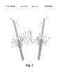
- FIG. 7is a sectional view taken on line 7--7 of FIG. 6.
- the lumbar osteosynthesis instrumentation shown in FIGS. 1 to 3is adapted to correct spondylolisthesis by the posterior approach.
- each lumbar vertebra to be correctedfor example the vertebra L5, two pedicular screws 1 having two screw threads, two cylindrical rods 2, preferably two rods of the so-called Cotrel type having surface asperities or knurling extending longitudinally along the concerned lumbar segment (vertebrae L5, L4 and sacrum S in the assembly shown in FIG. 1), connection elements 3 connecting each pedicular screw 1 to the adjacent rod 2, pedicular screws 4 for securing the rods 2 to the vertebra L4 and to the sacrum S, and devices 5 providing a transverse connection between the rods. All these elements except the pedicular screws 1 and the connection elements 3 are known per se and therefore need no special description.
- connection element 3has, when viewed in the transverse direction, a substantially L-shaped profile consisting of an enlarged base 3a in which is provided a through passage 10 receiving the rod 2 and having an axis X--X.
- This portion 3ahas on one side a cylindrical surface and on the other side a planar surface and is extended by a thin portion 3b.
- the latterhas two parallel planar surfaces and is provided with an opening 7 for the passage of the pedicular screw 1.
- the opening 7consists of a cylindrical central part having an axis Z--Z extended on each side by two conical parts 7b, 7c opening onto the planar surfaces.
- a tapped opening 6transversely opens onto the bore or passage 10 and receives a screw 20 for radially clamping the rod 2.
- the surface 3c of the element 3 remote from the passage 10is completely planar.
- the element 3constitutes the means for securing the rod 2 and the means for screwing the screw 1.
- the distance between the axes of the screw 1 and rod 2vary with the subject so that the surgeon can choose the most appropriate element 3.
- Each screw 1comprises from its point 8 a first screw threaded part 9 extending to the length of penetration of the screw 1 in the pedicular and a second screw threaded part 11 which is outside the region of penetration in the pedicle and is termed the "operating" part.
- the operating part 11On the side remote from the screw threaded part 9 the operating part 11 is extended by a profiled end portion 12, constituted for example by two flats 13 adapted to permit both the gripping of the double thread screw 1 and the screwing thereof by means of an ancillary device 14 (FIG. 5) which will be described hereinafter.
- the screw threaded operating part 11is extended by a short smooth region 15 terminating in a continuous peripheral shoulder 16 constituting the end of the screw threaded part 9.
- This shoulder 16bears against the planar surface of the element 3 which is the most remote from the screw threaded part 11, consequently the screw 1 cannot pass through the element 3.
- the screw thread 18 of this screw threaded partis adjacent the shoulder 16 and the depth of the thread 21 close to the shoulder 16 gradually diminishes until it tangentially merges with or fades onto a cylindrical sector 22 bordered by the shoulder 16 which thus forms a screw reinforcing region in this position.
- the shoulder 16may act as a support for a device or an associated connection element 3.
- the operating part 11 of the screw 1is constituted by a metal screw thread of small pitch, for example between 0.5 and 2 mm and preferably between 0.8 and 1 mm, adapted to receive a nut 23 for clamping the connection element 3 against the shoulder 16.
- connection element 3is made in a single piece not only makes this element cheaper to manufacture but also simplifies the positioning of the element by the surgeon, and above all improves the strength of the connection between the rod 2 having asperities and the pedicular screw 1.
- the pedicular double thread screw 1is subjected to high mechanical stresses of multiple origins; it must resist these various stresses for a relatively long period of time the duration of which depends on each patient.
- the screw 1must therefore be as simple as possible to mount during the surgical operations, but must also have sufficient strength to withstand all the forces during and after the operation.
- fracturesgenerally occur in the region between the two screw threads.
- the inventionremedies this situation by terminating the screw thread 18 for anchoring in the pedicle in the substantially tangential region 22. Consequently, the screw thread 18 does not "open out” onto the shoulder 16 for supporting the connection element 3 and consequently ensures that this shoulder 16 has a peripheral continuity and a sufficient supporting thickness. This supporting thickness thus affords the maximum mechanical resistance to the forces transmitted to the connection element 3 and therefore exerted by the latter.
- anchoring screw thread 18Another advantage afforded by this arrangement of the anchoring screw thread 18 resides in the fact that, when it is desired to effect a bicortical anchorage by reaching the opposite cortical part of the vertebra and with the screw thread length corresponding to the length of the passage through the vertebra, the surgeon is informed of the desired final position of the screw thread. The stoppage of the latter in its upper part indeed constitutes a warning in that the surgeon must suddenly exert a higher torque. He must therefore stop his screwing effort.
- the engagement of the pedicular screw 1 by the ancillary device 14no longer occurs in the central region of the screw, as described in said patent 2 615 095, but at the free end of the screw.
- This end regionmay be in the form of two flats 13 provided on a smooth, or optionally screw threaded, end part to permit the ancillary device 14 to act on the screw.
- This ancillary devicecomprises a rod 24 provided with a tubular end part 25 and, at its opposite end, a manual grip 26.
- the tubular part 25is so dimensioned as to permit the insertion therein of the operating part 11 of the screw 1, and the ancillary device 14 is completed by a tube or sleeve 27 coaxial with the rod 24 and slidably mounted on the latter so as to be capable of surrounding the tubular part 25 at the end of its travel.
- the tubular part 25is provided with longitudinal slots 28 starting at its free end, for example three slots as illustrated, extending along a part of the length of the region 25.
- the free end portion 29 of the latteris conical and tapers in the direction toward the grip 26.
- a hollow profile matching the profiled end portion 12 of the screwfor example, as shown in FIG. 5, two flats 31 whose longitudinal surfaces are parallel.
- the two flats 31are adapted to receive corresponding flats 13 of the screw 1 and thus lock the latter against rotation after the insertion of the operating part 11 in the tubular part 25.
- the flats 31are extended by longitudinal recesses 32 for receiving the operating part 11 of the screw 1.
- the tubular part 25is provided with a transverse opening 33 in the region of the flats.
- the surgeonslides the tube 27 along the tubular part 25 until the conical end portion 29 is made to grip round the operating part 11, the tapered portion 29 thus constituting a holding chuck for the screw 1.
- the two flatsconstitute additional means for preventing a reverse rotation of the pedicular screw 1 in the ancillary device 14.
- the ancillary device 14also serves to screw the nut 23 clamping the screw 1 in the connection element 3. It is provided in its end 29 with a corresponding recess for engaging this nut 23.
- the surgeonBefore placing in position the support rods 2, which are for example the known Cotrel rods (Registered Trademark), the surgeon suitably anchors with his ancillary device 14 the double thread screws 1 in each of the pedicles of the vertebra L5 to correct. Then he secures the support rods 2 to the neighbouring vertebrae, or, as in the embodiment shown in FIG. 1, to the sacrum S and vertebra L4. Then he firmly fixes the connection elements 3 to the rods 2 by means of a radial clamping screw 20 (FIG. 1).
- a radial clamping screw 20FIG. 1
- the two transverse connection rods 5are not yet installed.
- the surgeonacts on the nuts 23 clamping the connection elements 3 by means of an ancillary device and preferably two ancillary devices, each being disposed on one of the nuts 23 of the two screws 1. He is now free to act, as desired, more on the screwing of one of the nuts 23 than on the screwing of the other, depending on the movement he wishes to impart to the vertebra L5, as he is free to act in an identical manner on the two nuts 23.
- the fine pitch of the screw thread 11 supporting the correction nut 23permits acting very progressively on the vertebra.
- the lattersevers the double thread screw 1 above the nut 23. The severing of the rod deforms the screw thread 11 and this subsequently prevents the unscrewing of the nut 23.
- the instrumentation according to the inventionis easier to place in position by the surgeon than that disclosed in said French patent 2 615 095, cheaper as concerns the fabrication of the screw, and more reliable in use; it no longer requires a transverse handling plate in the region of the connection elements 3.
- the screwing of the pedicular screws 1 by their profiled end portions 12 rather than by their central regions as in the aforementioned prior instrumentation,is also more convenient for the surgeon.
- connection element 3may be constructed to have, as viewed in the transverse direction, a substantially L-shaped profile and be disposed in such manner that its planar surface 3c (in contact with the nut 23 in FIG. 3) is inverted, by turning the element round, so as to be closer to the adjacent vertebra.
Landscapes
- Health & Medical Sciences (AREA)
- Neurology (AREA)
- Orthopedic Medicine & Surgery (AREA)
- Life Sciences & Earth Sciences (AREA)
- Surgery (AREA)
- Heart & Thoracic Surgery (AREA)
- Engineering & Computer Science (AREA)
- Biomedical Technology (AREA)
- Nuclear Medicine, Radiotherapy & Molecular Imaging (AREA)
- Medical Informatics (AREA)
- Molecular Biology (AREA)
- Animal Behavior & Ethology (AREA)
- General Health & Medical Sciences (AREA)
- Public Health (AREA)
- Veterinary Medicine (AREA)
- Surgical Instruments (AREA)
Abstract
Description
The invention relates to lumbar osteosynthesis instrumentation for the correction of spondylolisthesis.
It is known that, substantially, spondylolisthesis is the forward displacement of a vertebra relative to its lower neighbour. In theory, any vertebra may be affected, but the fifth and the fourth lumbar vertebrae are the most commonly concerned.
Affecting more frequently women or young girls than men, spondylolisthesis is usually classified into five types: dysplastic, isthmian, traumatic, degenerative and pathological.
Its degree of seriousness is measured by the distance travelled through by the displaced vertebra with respect to its lower neighbour.
There are four stages:
The first stage is a displacement of a quarter of the antero-posterior diameter of the vertebral body.
The fourth stage corresponds to a complete displacement of the vertebral body.
The second and third stages are the intermediate stages.
Heretofore, although there are certain surgical techniques for the treatment of spondylolisthesis, either by the direct traction on the slipped vertebra, or by the screwing of the pedicles of this slipped vertebra, the reduction of the spondylolisthesis is not always satisfactory, above all in the cases of serious spondylolisthesis.
Surgery is indeed indicated for those who have a long past of lumbalgia or sciatica, in the case of evidence of a vertebral canal stenosis, a compression of the cauda equina or a subjacent motor lesion, or those whose spondylolisthesis rapidly evolves towardstage 3 orstage 4.
Generally, in surgery, an anterior or posterior vertebral fusion, laminectomy with decompression of the posterior structures and an excision of the hypertrophied mass of the fibrous tissue in the region of the lysis may be indicated.
In isthmian spondylolisthesis, the bilateral isthmian lyses are liable to be associated with a considerable pseudoarthrosis in relation with an emerging nerve root. The discal state in the region of the spondylolisthesis sometimes requires a radiculographic or discographic assessment. In vertebral canal stenoses, the decompression without fusion may be a surgical operation.
In actual fact, an effective orthopedic surgery consists in returning the vertebra not only onto the axis of the spine but also to a position which is as correct as possible relative to the neighbouring vertebrae. Over a period of time, or in the course of its displacement, this vertebra in fact might have been subjected to lateral thrusts which have caused it to pivot horizontally to a more or less large extent so that a correct repositioning of the vertebra of course implies its rearward return but also a derotation.
Attempts have already been made to correct spondylolisthesis, for example by means of devices consisting of two pedicular screws interconnected by a transverse plate which, by screwing a nut bearing against the plate, act solely by translation of the concerned vertebra for putting it into alignment with the neighbouring vertebrae.
Thus, the device disclosed inFrench patent 2 615 095 (87 06 864) employs two rods which are longitudinally fixed in the vertebral column with the aid of pedicular screws and each serve as support means for two screws having a double screw thread connected to the vertebra to be corrected. These two double thread screws are transversely connected by a rigid plate constituting a bipedicular base. It is this transverse plate which permits acting on the vertebra to be corrected owing to the provision of a median opening for receiving traction forceps.
In fact, such a device does not permit acting in a sufficiently satisfactory manner, and experience has shown that a traction on the median part of the plate has for effect to rearwardly return the vertebra to be corrected too rapidly. Further, if this vertebra must be derotated, it has been found that the presence of the plate is liable to prevent the required derotation action owing to the fact that this induces at the same time a certain return of the vertebra.
Now, surgical experience has revealed that it is desirable to act slowly on the vertebra by acting on each one of the double thread screws independently, so that the surgeon can gradually adjust for each particular case his vertebra derotation and/or return action.
Moreover, such a device is relatively complex and costly owing to the number of its component parts which further increases the mounting difficulties encountered by the surgeon during the surgical operation. As concerns in particular the double thread screw, in addition to the fact that it is long and costly to produce, its implantation in the pedicles is not at all convenient.
Further, this double thread screw is subjected to extremely high shear stresses, mainly in the region of the junction with the instrumentation appliances or in the upper part of the screw thread.
An object of the invention is to provide a lumbar osteosynthesis instrumentation for the correction of spondylolisthesis, which permits both returning the vertebra to the rear and pivoting it in the desired direction of rotation. Another object of the invention is to provide a double thread pedicular screw so arranged as to overcome the aforementioned drawbacks while permitting mass production which is cheaper than in the case of screws known in the art which can only be produced on a small scale.
The osteosynthesis instrumentation according to the invention comprises, for each lumbar vertebra, two pedicular double thread screws, one thread of which corresponds to the region of penetration of the screw in the pedicle, two rods having surface asperities respectively associated with a pedicular screw and connected to the latter by connection elements provided with elements for clamping the rods.
According to the invention, each connection element is in one piece and the screw thread corresponding to the region of penetration of the screw in the pedicle terminates on an annular shoulder on which the connection element bears.
The derotation action exerted by means of this instrumentation has the advantage that it can be carried out slowly and with a certain amount of control over the movements, thereby affording on the whole in the two movements an excellent precision in the repositioning of the vertebra relative to its neighbouring vertebrae.
Further, the arrangement of a transverse shoulder into which tangentially fades the screw thread of the part of the screw serving to penetrate the pedicle, provides a reinforcement or strengthening resisting the shear stresses in this region. The continuous peripheral shoulder may also act as a support for an added part.
According to a particular feature of the invention, the end of the screw thread outside the part of the screw serving to penetrate the pedicle is extended by a screw threaded rod adapted to cooperate with an ancillary screwing device.
The instrumentation according to the invention comprises an ancillary device for screwing the pedicular double thread screw, this device bearing against the screw threaded extension of said screw. This ancillary device comprises a rod provided with an end grip and includes a tubular end part which is arranged to permit the insertion of the operating part of the double thread screw, has a conical free end part remote from the grip tapering toward the grip and is provided with at least one longitudinal slot. This ancillary device further comprises a tube freely slidable on the rod for the purpose of surrounding and gripping the conical end part of its tubular end part for the purpose of clamping it on the operating part of the pedicular screw.
With this ancillary device, the length of the operating screw thread is almost completely enclosed in the tubular end part and clamped owing to the action of the second tube when the latter surrounds the conical end part of the tubular end part. After having provided a prior bore in the pedicle, the surgeon can in this way easily screw the double thread screw in position.
Further features and advantages of the invention will be apparent from the following description with reference to the accompanying drawings which illustrate two embodiments of the invention by way of non-limitative examples.
In the drawings:
FIG. 1 is a perspective view from above of one embodiment of the lumbar osteosynthesis instrumentation according to the invention, mounted on the first lumbar vertebra and on the sacrum.
FIG. 2 is a partial perspective view of the instrumentation shown in FIG. 1.
FIG. 3 is an elevational view in the transverse direction, partly in section, of the instrumentation shown in FIGS. 1 and 2.
FIG. 4 is an elevational view to a larger scale of a pedicular double thread screw which is part of the instrumentation shown in FIGS. 1 to 3.
FIG. 5 is a perspective view of an embodiment of the ancillary device for mounting the pedicular screw shown in FIG. 4.
FIG. 6 is a perspective view to a larger scale of an alternative embodiment of the connection element between the osteosynthesis rod and the screw.
FIG. 7 is a sectional view taken online 7--7 of FIG. 6.
The lumbar osteosynthesis instrumentation shown in FIGS. 1 to 3 is adapted to correct spondylolisthesis by the posterior approach.
It comprises, for each lumbar vertebra to be corrected, for example the vertebra L5, twopedicular screws 1 having two screw threads, twocylindrical rods 2, preferably two rods of the so-called Cotrel type having surface asperities or knurling extending longitudinally along the concerned lumbar segment (vertebrae L5, L4 and sacrum S in the assembly shown in FIG. 1),connection elements 3 connecting eachpedicular screw 1 to theadjacent rod 2,pedicular screws 4 for securing therods 2 to the vertebra L4 and to the sacrum S, anddevices 5 providing a transverse connection between the rods. All these elements except thepedicular screws 1 and theconnection elements 3 are known per se and therefore need no special description.
Eachconnection element 3 has, when viewed in the transverse direction, a substantially L-shaped profile consisting of an enlargedbase 3a in which is provided a throughpassage 10 receiving therod 2 and having an axis X--X. Thisportion 3a has on one side a cylindrical surface and on the other side a planar surface and is extended by athin portion 3b. The latter has two parallel planar surfaces and is provided with anopening 7 for the passage of thepedicular screw 1. Theopening 7 consists of a cylindrical central part having an axis Z--Z extended on each side by twoconical parts screw 11 relative to the axis Z--Z of about ±15°, the angular limits of this axis corresponding to the axes Y--Y and Y'--Y' (FIG. 7). A tapped opening 6 transversely opens onto the bore orpassage 10 and receives ascrew 20 for radially clamping therod 2. Thesurface 3c of theelement 3 remote from thepassage 10 is completely planar.
Theelement 3 constitutes the means for securing therod 2 and the means for screwing thescrew 1. The distance between the axes of thescrew 1 androd 2 vary with the subject so that the surgeon can choose the mostappropriate element 3.
Eachscrew 1 comprises from its point 8 a first screw threadedpart 9 extending to the length of penetration of thescrew 1 in the pedicular and a second screw threadedpart 11 which is outside the region of penetration in the pedicle and is termed the "operating" part. On the side remote from the screw threadedpart 9 theoperating part 11 is extended by a profiledend portion 12, constituted for example by twoflats 13 adapted to permit both the gripping of thedouble thread screw 1 and the screwing thereof by means of an ancillary device 14 (FIG. 5) which will be described hereinafter.
At the end remote from the profiledend portion 12, the screw threaded operatingpart 11 is extended by a short smooth region 15 terminating in a continuousperipheral shoulder 16 constituting the end of the screw threadedpart 9. Thisshoulder 16 bears against the planar surface of theelement 3 which is the most remote from the screw threadedpart 11, consequently thescrew 1 cannot pass through theelement 3.
Thescrew thread 18 of this screw threaded part is adjacent theshoulder 16 and the depth of thethread 21 close to theshoulder 16 gradually diminishes until it tangentially merges with or fades onto acylindrical sector 22 bordered by theshoulder 16 which thus forms a screw reinforcing region in this position. Theshoulder 16 may act as a support for a device or an associatedconnection element 3.
The operatingpart 11 of thescrew 1 is constituted by a metal screw thread of small pitch, for example between 0.5 and 2 mm and preferably between 0.8 and 1 mm, adapted to receive anut 23 for clamping theconnection element 3 against theshoulder 16.
This instrumentation has the following advantages:
The fact that theconnection element 3 is made in a single piece not only makes this element cheaper to manufacture but also simplifies the positioning of the element by the surgeon, and above all improves the strength of the connection between therod 2 having asperities and thepedicular screw 1.
As previously explained, the pediculardouble thread screw 1 is subjected to high mechanical stresses of multiple origins; it must resist these various stresses for a relatively long period of time the duration of which depends on each patient. Thescrew 1 must therefore be as simple as possible to mount during the surgical operations, but must also have sufficient strength to withstand all the forces during and after the operation. Now, with the pedicular screws employed heretofore, it has been found that fractures generally occur in the region between the two screw threads. The invention remedies this situation by terminating thescrew thread 18 for anchoring in the pedicle in the substantiallytangential region 22. Consequently, thescrew thread 18 does not "open out" onto theshoulder 16 for supporting theconnection element 3 and consequently ensures that thisshoulder 16 has a peripheral continuity and a sufficient supporting thickness. This supporting thickness thus affords the maximum mechanical resistance to the forces transmitted to theconnection element 3 and therefore exerted by the latter.
Another advantage afforded by this arrangement of the anchoringscrew thread 18 resides in the fact that, when it is desired to effect a bicortical anchorage by reaching the opposite cortical part of the vertebra and with the screw thread length corresponding to the length of the passage through the vertebra, the surgeon is informed of the desired final position of the screw thread. The stoppage of the latter in its upper part indeed constitutes a warning in that the surgeon must suddenly exert a higher torque. He must therefore stop his screwing effort.
Owing to the provision of the profiledend portion 12, the engagement of thepedicular screw 1 by theancillary device 14 no longer occurs in the central region of the screw, as described in saidpatent 2 615 095, but at the free end of the screw. This end region may be in the form of twoflats 13 provided on a smooth, or optionally screw threaded, end part to permit theancillary device 14 to act on the screw.
This ancillary device comprises arod 24 provided with atubular end part 25 and, at its opposite end, amanual grip 26. Thetubular part 25 is so dimensioned as to permit the insertion therein of the operatingpart 11 of thescrew 1, and theancillary device 14 is completed by a tube orsleeve 27 coaxial with therod 24 and slidably mounted on the latter so as to be capable of surrounding thetubular part 25 at the end of its travel.
Thetubular part 25 is provided withlongitudinal slots 28 starting at its free end, for example three slots as illustrated, extending along a part of the length of theregion 25. Thefree end portion 29 of the latter is conical and tapers in the direction toward thegrip 26. Beyond theslots 28, at a certain distance from the latter, there is provided a hollow profile matching the profiledend portion 12 of the screw, for example, as shown in FIG. 5, twoflats 31 whose longitudinal surfaces are parallel. The twoflats 31 are adapted to receive correspondingflats 13 of thescrew 1 and thus lock the latter against rotation after the insertion of the operatingpart 11 in thetubular part 25. In the direction toward theconical end part 29, theflats 31 are extended bylongitudinal recesses 32 for receiving the operatingpart 11 of thescrew 1. Lastly, in order to permit a visual checking of the position of the profiledend portion 12 on theflats 31, thetubular part 25 is provided with atransverse opening 33 in the region of the flats.
When the operatingpart 11 is inserted in thetubular part 25 with itsend portion 12 locked against rotation between theflats 31, the surgeon slides thetube 27 along thetubular part 25 until theconical end portion 29 is made to grip round theoperating part 11, the taperedportion 29 thus constituting a holding chuck for thescrew 1. The two flats constitute additional means for preventing a reverse rotation of thepedicular screw 1 in theancillary device 14. Theancillary device 14 also serves to screw thenut 23 clamping thescrew 1 in theconnection element 3. It is provided in itsend 29 with a corresponding recess for engaging thisnut 23.
The instrumentation just described is used in the following manner.
Before placing in position thesupport rods 2, which are for example the known Cotrel rods (Registered Trademark), the surgeon suitably anchors with hisancillary device 14 thedouble thread screws 1 in each of the pedicles of the vertebra L5 to correct. Then he secures thesupport rods 2 to the neighbouring vertebrae, or, as in the embodiment shown in FIG. 1, to the sacrum S and vertebra L4. Then he firmly fixes theconnection elements 3 to therods 2 by means of a radial clamping screw 20 (FIG. 1).
At this stage, the twotransverse connection rods 5 are not yet installed. In order to correct the vertebra L5, i.e. to return it rearwardly (spondylolisthesis) and/or derotate it, the surgeon acts on the nuts 23 clamping theconnection elements 3 by means of an ancillary device and preferably two ancillary devices, each being disposed on one of thenuts 23 of the twoscrews 1. He is now free to act, as desired, more on the screwing of one of the nuts 23 than on the screwing of the other, depending on the movement he wishes to impart to the vertebra L5, as he is free to act in an identical manner on the two nuts 23.
Each time the surgeon acts on one of the nuts 23, he exerts by the bearing of the screw thread-nut system on theconnection element 3 firmly connected to thesupport rod 2, a traction on the vertebra L5 in a direction toward theconnection element 3. When he acts on a single one of the nuts 23, he also produces a slight rotation of the vertebra L5 about itself. When he acts equally on bothnuts 23, he produces a rearward return of the vertebra L5.
In all cases, the fine pitch of thescrew thread 11 supporting thecorrection nut 23 permits acting very progressively on the vertebra. When the vertebra is finally in the position required by the surgeon, the latter severs thedouble thread screw 1 above thenut 23. The severing of the rod deforms thescrew thread 11 and this subsequently prevents the unscrewing of thenut 23.
It is only at this moment that thetransverse rods 5 interconnecting therods 2 can be mounted, thereby achieving a rectangulation of the whole final instrumentation.
The instrumentation according to the invention is easier to place in position by the surgeon than that disclosed in saidFrench patent 2 615 095, cheaper as concerns the fabrication of the screw, and more reliable in use; it no longer requires a transverse handling plate in the region of theconnection elements 3. The screwing of thepedicular screws 1 by their profiledend portions 12 rather than by their central regions as in the aforementioned prior instrumentation, is also more convenient for the surgeon.
It must be understood that the scope of the invention is not intended to be limited to the described embodiments and various modifications may be made. For example, it is obvious that theend portion 12 may have any suitable profile other than that described, the same being true of the corresponding twoflats 31 of theancillary device 14.
Likewise, in the alternative embodiment shown in FIG. 6, theconnection element 3 may be constructed to have, as viewed in the transverse direction, a substantially L-shaped profile and be disposed in such manner that itsplanar surface 3c (in contact with thenut 23 in FIG. 3) is inverted, by turning the element round, so as to be closer to the adjacent vertebra.
Claims (5)
1. A spinal fixation system, comprising:
an elongated rod configured for attachment along a posterior aspect of a patient's spine, a set screw, and a nut;
a pedicular screw having a first screw thread and a second screw thread, said first thread being configured for penetration into a posterior pedicular region of the patient's spine, said second thread being separated from said first thread by a bearing shoulder therebetween, said second thread being configured to extend outside the pedicular region when penetrated by said first thread;
a connection element having a generally L-shaped profile defining a rod bore receiving said rod therethrough and a threaded bore intersecting said rod bore, said set screw being threaded into said threaded bore to correspondingly clamp said rod to said element, said element having two opposed planar surfaces defining an opening configured to receive said pedicular screw therethrough, said opening having a cylindrical central part extended at both ends by conical parts each opening out onto a respective one of said planar surfaces, said element bearing against said shoulder of said pedicular screw, said nut being threaded on said second thread of said pedicular screw fastening said pedicular screw to said element; and
wherein said set screw is positioned anterior to said nut to provide a low profile construct when said rod and said pedicular screw are rigidly interconnected by said element.
2. The system according to claim 1, wherein said connection element is defined by a single unitary piece having a generally flat, planar posterior surface without protrusions.
3. The system according to claim 1, wherein said set screw is configured not to extend posterior to a generally flat, planar surface of said element when securely threaded into said threaded bore.
4. The system according to claim 1, wherein said cylindrical central part and said conical parts of said opening permit selection of an angular inclination of said pedicular screw through said opening from a range of about 30°.
5. The system according to claim 1, further comprising:
an ancillary device for screwing said pedicular screw by an operating part thereof, said operating part extending outside the pedicular region of penetration of said pedicular screw, said ancillary device including a rod provided with an end grip and a tubular end part which is arranged to permit the insertion therein of said operating part of said pedicular screw, said tubular end part having a conical free end portion remote from said grip an tapering in a direction toward said grip and defining at least one longitudinal slot, and a tube freely slidably mounted on said rod of said device configured for surrounding said conical free end portion of said tubular end part to grip said operating part of said pedicular screw.
Priority Applications (1)
| Application Number | Priority Date | Filing Date | Title |
|---|---|---|---|
| US08/436,192US5814046A (en) | 1992-11-13 | 1993-11-12 | Pedicular screw and posterior spinal instrumentation |
Applications Claiming Priority (4)
| Application Number | Priority Date | Filing Date | Title |
|---|---|---|---|
| FR9213694AFR2697991B1 (en) | 1992-11-13 | 1992-11-13 | Lumbosacral osteosynthesis instrumentation for the correction of spondylolisthesis by posterior route, and instrumentation screws. |
| FR9213694 | 1992-11-13 | ||
| PCT/US1993/010966WO1994010928A1 (en) | 1992-11-13 | 1993-11-12 | Pedicular screw and posterior spinal instrumentation |
| US08/436,192US5814046A (en) | 1992-11-13 | 1993-11-12 | Pedicular screw and posterior spinal instrumentation |
Publications (1)
| Publication Number | Publication Date |
|---|---|
| US5814046Atrue US5814046A (en) | 1998-09-29 |
Family
ID=26229868
Family Applications (1)
| Application Number | Title | Priority Date | Filing Date |
|---|---|---|---|
| US08/436,192Expired - LifetimeUS5814046A (en) | 1992-11-13 | 1993-11-12 | Pedicular screw and posterior spinal instrumentation |
Country Status (1)
| Country | Link |
|---|---|
| US (1) | US5814046A (en) |
Cited By (117)
| Publication number | Priority date | Publication date | Assignee | Title |
|---|---|---|---|---|
| US6083227A (en)* | 1997-09-22 | 2000-07-04 | Sofamor S.N.C. | Bone screw and method for manufacturing said screw |
| US6210413B1 (en)* | 1999-04-23 | 2001-04-03 | Sdgi Holdings, Inc. | Connecting apparatus using shape-memory technology |
| US6248104B1 (en)* | 1997-04-01 | 2001-06-19 | Daniel Chopin | Apparatus for osteosynthesis comprising a connector of the spinal pin and the anchoring elements |
| DE20010206U1 (en)* | 2000-06-09 | 2001-10-18 | BIOMET MERCK Deutschland GmbH, 14167 Berlin | Holder for a pedicle screw |
| US6461359B1 (en) | 1999-11-10 | 2002-10-08 | Clifford Tribus | Spine stabilization device |
| US6478798B1 (en) | 2001-05-17 | 2002-11-12 | Robert S. Howland | Spinal fixation apparatus and methods for use |
| US6524315B1 (en) | 2000-08-08 | 2003-02-25 | Depuy Acromed, Inc. | Orthopaedic rod/plate locking mechanism |
| US20030105460A1 (en)* | 2000-03-15 | 2003-06-05 | Dennis Crandall | Multidirectional pivoting bone screw and fixation system |
| US20030220643A1 (en)* | 2002-05-24 | 2003-11-27 | Ferree Bret A. | Devices to prevent spinal extension |
| US20040002707A1 (en)* | 2002-06-28 | 2004-01-01 | Chunfeng Zhao | Spinal fixation support device and methods of using |
| US20040087949A1 (en)* | 2002-10-31 | 2004-05-06 | Bono Frank S. | Snap-in washers and assemblies thereof |
| US6743231B1 (en) | 2000-10-02 | 2004-06-01 | Sulzer Spine-Tech Inc. | Temporary spinal fixation apparatuses and methods |
| US6755829B1 (en) | 2000-09-22 | 2004-06-29 | Depuy Acromed, Inc. | Lock cap anchor assembly for orthopaedic fixation |
| US20040127908A1 (en)* | 2001-09-25 | 2004-07-01 | Roman Shawn David | Cranial clamp with torque-limiting feature |
| US6770075B2 (en) | 2001-05-17 | 2004-08-03 | Robert S. Howland | Spinal fixation apparatus with enhanced axial support and methods for use |
| US20040153070A1 (en)* | 2003-02-03 | 2004-08-05 | Barker B. Thomas | Midline occipital vertebral fixation system |
| US20040193161A1 (en)* | 2001-10-03 | 2004-09-30 | Vaughan Paul A. | Vertebral stabilization assembly and method |
| US20050070901A1 (en)* | 2003-09-26 | 2005-03-31 | Stryker Spine | Bone fixation assembly and method |
| US20050216001A1 (en)* | 2004-03-23 | 2005-09-29 | Stryker Spine | Sphere and bone plate |
| US20060036252A1 (en)* | 2004-08-12 | 2006-02-16 | Baynham Bret O | Polyaxial screw |
| US20060036246A1 (en)* | 2004-08-03 | 2006-02-16 | Carl Allen L | Device and method for correcting a spinal deformity |
| US20060036242A1 (en)* | 2004-08-10 | 2006-02-16 | Nilsson C M | Screw and rod fixation system |
| US20060036259A1 (en)* | 2004-08-03 | 2006-02-16 | Carl Allen L | Spine treatment devices and methods |
| US20060058790A1 (en)* | 2004-08-03 | 2006-03-16 | Carl Allen L | Spinous process reinforcement device and method |
| US20060058787A1 (en)* | 2004-08-24 | 2006-03-16 | Stryker Spine | Spinal implant assembly |
| US20060069393A1 (en)* | 2000-08-22 | 2006-03-30 | Pathak Kartikeya P | Renew compression screw |
| US20060095037A1 (en)* | 2004-10-29 | 2006-05-04 | Jones Bryan S | Connector assemblies for connecting a bone anchor to a fixation element |
| US7041136B2 (en) | 2000-11-29 | 2006-05-09 | Facet Solutions, Inc. | Facet joint replacement |
| US20060106380A1 (en)* | 2003-10-21 | 2006-05-18 | Innovative Spinal Technologies | Extension for use with stabilization systems for internal structures |
| US7074237B2 (en) | 2000-12-13 | 2006-07-11 | Facet Solutions, Inc. | Multiple facet joint replacement |
| US20060155284A1 (en)* | 2005-01-07 | 2006-07-13 | Depuy Spine Sarl | Occipital plate and guide systems |
| US7090698B2 (en) | 2001-03-02 | 2006-08-15 | Facet Solutions | Method and apparatus for spine joint replacement |
| US20060264934A1 (en)* | 2005-05-18 | 2006-11-23 | Medicinelodge, Inc. | System and method for orthopedic implant configuration |
| US20060293661A1 (en)* | 2005-06-08 | 2006-12-28 | Rsb Spine Llc | Procedure for aligning and stabilizing bone elements |
| US20070016189A1 (en)* | 2005-06-30 | 2007-01-18 | Depuy Spine Sarl | Orthopedic clamping hook assembly |
| US20070093824A1 (en)* | 2005-09-22 | 2007-04-26 | Hestad Hugh D | Pedicle fixation rod alignment system |
| US20070149973A1 (en)* | 2003-06-27 | 2007-06-28 | Medicrea Technologies | Vertebral osteosynthesis equipment |
| US20070213715A1 (en)* | 2006-02-09 | 2007-09-13 | Sdgi Holdings, Inc. | Spinal derotation instruments and methods |
| US20070213716A1 (en)* | 2006-02-09 | 2007-09-13 | Sdgi Holdings, Inc. | Methods and instruments for spinal derotation |
| US20070233079A1 (en)* | 2006-02-06 | 2007-10-04 | Stryker Spine | Rod contouring apparatus and method for percutaneous pedicle screw extension |
| US20070233095A1 (en)* | 2004-10-07 | 2007-10-04 | Schlaepfer Fridolin J | Device for dynamic stabilization of bones or bone fragments |
| US7314467B2 (en) | 2002-04-24 | 2008-01-01 | Medical Device Advisory Development Group, Llc. | Multi selective axis spinal fixation system |
| US20080015694A1 (en)* | 2006-01-13 | 2008-01-17 | Clifford Tribus | Spine reduction and stabilization device |
| US20080125813A1 (en)* | 2006-09-21 | 2008-05-29 | Warsaw Orthopedic, Inc. | Low profile vertebral stabilization systems and methods |
| US20080147128A1 (en)* | 2006-12-15 | 2008-06-19 | Zimmer Technology, Inc. | Cannulated bone screw and cannulated driver for the implantation thereof |
| US20080234746A1 (en)* | 2003-09-24 | 2008-09-25 | N Spine, Inc. | Spinal stabilization device |
| US20080249579A1 (en)* | 2007-04-04 | 2008-10-09 | Warsaw Orthopedic, Inc. | Variable flank bone screw |
| US20090018658A1 (en)* | 2006-08-09 | 2009-01-15 | Nuvasive, Inc. | Methods and apparatus for treating spinal stenosis |
| US20090042164A1 (en)* | 2007-07-25 | 2009-02-12 | Machata William C | Driver tip for engaging and releasing an orthodontic bone screw |
| US7507242B2 (en) | 2004-06-02 | 2009-03-24 | Facet Solutions | Surgical measurement and resection framework |
| US7566345B1 (en) | 2001-03-01 | 2009-07-28 | Facet Solutions, Inc | Prosthesis for the replacement of a posterior element of a vertebra |
| US20090216277A1 (en)* | 2008-02-26 | 2009-08-27 | Clariance | Posterior lumbar joint prosthesis |
| US7588590B2 (en) | 2003-12-10 | 2009-09-15 | Facet Solutions, Inc | Spinal facet implant with spherical implant apposition surface and bone bed and methods of use |
| US20090287254A1 (en)* | 2008-05-13 | 2009-11-19 | Warsaw Orthopedic, Inc. | Ilio-Sacral Connector System and Method |
| US7628799B2 (en) | 2005-08-23 | 2009-12-08 | Aesculap Ag & Co. Kg | Rod to rod connector |
| US20100069964A1 (en)* | 2006-06-28 | 2010-03-18 | Beat Lechmann | Dynamic fixation system |
| US7722647B1 (en) | 2005-03-14 | 2010-05-25 | Facet Solutions, Inc. | Apparatus and method for posterior vertebral stabilization |
| US7744632B2 (en) | 2006-12-20 | 2010-06-29 | Aesculap Implant Systems, Inc. | Rod to rod connector |
| US7763052B2 (en) | 2003-12-05 | 2010-07-27 | N Spine, Inc. | Method and apparatus for flexible fixation of a spine |
| US7766911B1 (en) | 2002-07-05 | 2010-08-03 | Theken Spine, Llc | Fixed and variable locking fixation assembly |
| US7815665B2 (en) | 2003-09-24 | 2010-10-19 | N Spine, Inc. | Adjustable spinal stabilization system |
| US20110106082A1 (en)* | 2009-10-30 | 2011-05-05 | Warsaw Orthopedic, Inc. | Instruments and systems for vertebral column manipulation |
| US20110112580A1 (en)* | 2003-06-27 | 2011-05-12 | Medicrea Technologies | Vertebral osteosynthesis equipment |
| US7959653B2 (en) | 2004-09-03 | 2011-06-14 | Lanx, Inc. | Spinal rod cross connector |
| US7967826B2 (en) | 2003-10-21 | 2011-06-28 | Theken Spine, Llc | Connector transfer tool for internal structure stabilization systems |
| US7993370B2 (en) | 2003-09-24 | 2011-08-09 | N Spine, Inc. | Method and apparatus for flexible fixation of a spine |
| US7993373B2 (en) | 2005-02-22 | 2011-08-09 | Hoy Robert W | Polyaxial orthopedic fastening apparatus |
| US20110230914A1 (en)* | 2007-08-07 | 2011-09-22 | Synthes (U.S.A.) | Dynamic cable system |
| US8075604B2 (en) | 2006-02-16 | 2011-12-13 | Warsaw Orthopedic, Inc. | Multi-thread bone screw and method |
| US8114158B2 (en) | 2004-08-03 | 2012-02-14 | Kspine, Inc. | Facet device and method |
| US8162979B2 (en) | 2007-06-06 | 2012-04-24 | K Spine, Inc. | Medical device and method to correct deformity |
| US8167915B2 (en) | 2005-09-28 | 2012-05-01 | Nuvasive, Inc. | Methods and apparatus for treating spinal stenosis |
| US8206394B2 (en) | 2009-05-13 | 2012-06-26 | Depuy Spine, Inc. | Torque limited instrument for manipulating a spinal rod relative to a bone anchor |
| US8206418B2 (en) | 2007-01-10 | 2012-06-26 | Gmedelaware 2 Llc | System and method for facet joint replacement with detachable coupler |
| WO2012135870A3 (en)* | 2011-04-01 | 2012-11-22 | Stachniak Rebecca Elizabeth | Posterior cervical stabilization system and method |
| US8357183B2 (en) | 2009-03-26 | 2013-01-22 | Kspine, Inc. | Semi-constrained anchoring system |
| US8556936B2 (en) | 2000-11-29 | 2013-10-15 | Gmedelaware 2 Llc | Facet joint replacement |
| US8562649B2 (en) | 2004-02-17 | 2013-10-22 | Gmedelaware 2 Llc | System and method for multiple level facet joint arthroplasty and fusion |
| US8608746B2 (en) | 2008-03-10 | 2013-12-17 | DePuy Synthes Products, LLC | Derotation instrument with reduction functionality |
| US8623057B2 (en) | 2003-09-24 | 2014-01-07 | DePuy Synthes Products, LLC | Spinal stabilization device |
| US8709044B2 (en) | 2005-03-04 | 2014-04-29 | DePuy Synthes Products, LLC | Instruments and methods for manipulating vertebra |
| US8709015B2 (en) | 2008-03-10 | 2014-04-29 | DePuy Synthes Products, LLC | Bilateral vertebral body derotation system |
| US8734497B2 (en) | 2009-03-13 | 2014-05-27 | The University Of Toledo | Removable anchoring pedicle screw |
| US8764801B2 (en) | 2005-03-28 | 2014-07-01 | Gmedelaware 2 Llc | Facet joint implant crosslinking apparatus and method |
| US8771319B2 (en) | 2012-04-16 | 2014-07-08 | Aesculap Implant Systems, Llc | Rod to rod cross connector |
| US8821546B2 (en) | 2007-11-06 | 2014-09-02 | Stanus Investments, Inc. | Vertebral screw arrangement with locking pin |
| US8828058B2 (en) | 2008-11-11 | 2014-09-09 | Kspine, Inc. | Growth directed vertebral fixation system with distractible connector(s) and apical control |
| US8828056B2 (en) | 2012-04-16 | 2014-09-09 | Aesculap Implant Systems, Llc | Rod to rod cross connector |
| US8900273B2 (en) | 2005-02-22 | 2014-12-02 | Gmedelaware 2 Llc | Taper-locking fixation system |
| US8920472B2 (en) | 2011-11-16 | 2014-12-30 | Kspine, Inc. | Spinal correction and secondary stabilization |
| US8992576B2 (en) | 2008-12-17 | 2015-03-31 | DePuy Synthes Products, LLC | Posterior spine dynamic stabilizer |
| US8998961B1 (en) | 2009-02-26 | 2015-04-07 | Lanx, Inc. | Spinal rod connector and methods |
| US9095379B2 (en) | 2005-03-04 | 2015-08-04 | Medos International Sarl | Constrained motion bone screw assembly |
| US9101416B2 (en) | 2003-01-24 | 2015-08-11 | DePuy Synthes Products, Inc. | Spinal rod approximator |
| US9138261B2 (en) | 2010-04-06 | 2015-09-22 | Seaspine, Inc. | System and methods for correcting spinal deformities |
| US9168071B2 (en) | 2009-09-15 | 2015-10-27 | K2M, Inc. | Growth modulation system |
| US9179957B2 (en) | 2012-08-09 | 2015-11-10 | Spinecraft, LLC | Systems, assemblies and methods for spinal derotation |
| US9333009B2 (en) | 2011-06-03 | 2016-05-10 | K2M, Inc. | Spinal correction system actuators |
| US9451987B2 (en) | 2011-11-16 | 2016-09-27 | K2M, Inc. | System and method for spinal correction |
| US9468471B2 (en) | 2013-09-17 | 2016-10-18 | K2M, Inc. | Transverse coupler adjuster spinal correction systems and methods |
| US9468469B2 (en) | 2011-11-16 | 2016-10-18 | K2M, Inc. | Transverse coupler adjuster spinal correction systems and methods |
| US9468468B2 (en) | 2011-11-16 | 2016-10-18 | K2M, Inc. | Transverse connector for spinal stabilization system |
| US9510875B2 (en) | 2013-03-14 | 2016-12-06 | Stryker European Holdings I, Llc | Systems and methods for percutaneous spinal fusion |
| US9700357B2 (en) | 2003-09-24 | 2017-07-11 | Stryker European Holdings I, Llc | Methods and devices for improving percutaneous access in minimally invasive surgeries |
| CN107137136A (en)* | 2017-05-12 | 2017-09-08 | 王文军 | The connectivity kit of subcutaneous flexible spinal internal fixation system |
| US9763702B2 (en) | 2012-11-16 | 2017-09-19 | DePuy Synthes Products, Inc. | Bone fixation assembly |
| US9827020B2 (en) | 2013-03-14 | 2017-11-28 | Stryker European Holdings I, Llc | Percutaneous spinal cross link system and method |
| US9861393B2 (en) | 2012-08-09 | 2018-01-09 | Spinecraft, LLC | Systems, assemblies and methods for spinal derotation |
| US10034690B2 (en) | 2014-12-09 | 2018-07-31 | John A. Heflin | Spine alignment system |
| US10098665B2 (en) | 2012-08-01 | 2018-10-16 | DePuy Synthes Products, Inc. | Spine derotation system |
| US10265110B2 (en) | 2015-10-19 | 2019-04-23 | Alphatec Spine, Inc. | Pedicle screw with raised root |
| US10499964B2 (en) | 2010-03-08 | 2019-12-10 | Biedermann Technologies Gmbh & Co. Kg | Locking element for a polyaxial bone anchor, bone plate assembly and tool |
| US10702311B2 (en) | 2011-11-16 | 2020-07-07 | K2M, Inc. | Spinal correction and secondary stabilization |
| US10905473B2 (en) | 2016-02-15 | 2021-02-02 | Asro Medical | Transverse, and surgical instrument |
| US10973556B2 (en) | 2008-06-17 | 2021-04-13 | DePuy Synthes Products, Inc. | Adjustable implant assembly |
| US11707307B2 (en) | 2020-12-04 | 2023-07-25 | Globus Medical, Inc. | Systems and methods for treating rib fractures and osteotomies using implantation |
| US12102364B2 (en) | 2020-12-04 | 2024-10-01 | Globus Medical, Inc. | Systems and methods for treating rib fractures and osteotomies using implantation |
Citations (15)
| Publication number | Priority date | Publication date | Assignee | Title |
|---|---|---|---|---|
| US2532972A (en)* | 1947-04-18 | 1950-12-05 | Donald D Vertin | Screw holder and starter |
| US2634641A (en)* | 1950-02-20 | 1953-04-14 | Charles L Hodges | Fastener-holding socket wrench |
| US3068922A (en)* | 1959-08-17 | 1962-12-18 | Roberts Co | Locking screwdriver |
| US3377894A (en)* | 1967-01-03 | 1968-04-16 | Glen M. Johnson | Sink ring fastener tool |
| US3604487A (en)* | 1969-03-10 | 1971-09-14 | Richard S Gilbert | Orthopedic screw driving means |
| US4393583A (en)* | 1981-03-17 | 1983-07-19 | Motorola Inc. | Anti-torque connection apparatus and method for using |
| US4648388A (en)* | 1985-11-01 | 1987-03-10 | Acromed Corporation | Apparatus and method for maintaining vertebrae in a desired relationship |
| US4877020A (en)* | 1984-11-30 | 1989-10-31 | Vich Jose M O | Apparatus for bone graft |
| US5024213A (en)* | 1989-02-08 | 1991-06-18 | Acromed Corporation | Connector for a corrective device |
| US5030220A (en)* | 1990-03-29 | 1991-07-09 | Advanced Spine Fixation Systems Incorporated | Spine fixation system |
| US5129900A (en)* | 1990-07-24 | 1992-07-14 | Acromed Corporation | Spinal column retaining method and apparatus |
| US5147363A (en)* | 1989-12-21 | 1992-09-15 | Haerle Anton | Screw for use in osteosynthesis |
| US5507211A (en)* | 1994-06-23 | 1996-04-16 | Amei Technologies Inc. | Releasable socket |
| US5520688A (en)* | 1994-07-20 | 1996-05-28 | Lin; Chih-I | Vertebral auxiliary fixation device |
| US5545163A (en)* | 1991-07-15 | 1996-08-13 | Danek Medical, Inc. | Spinal fixation system |
- 1993
- 1993-11-12USUS08/436,192patent/US5814046A/ennot_activeExpired - Lifetime
Patent Citations (17)
| Publication number | Priority date | Publication date | Assignee | Title |
|---|---|---|---|---|
| US2532972A (en)* | 1947-04-18 | 1950-12-05 | Donald D Vertin | Screw holder and starter |
| US2634641A (en)* | 1950-02-20 | 1953-04-14 | Charles L Hodges | Fastener-holding socket wrench |
| US3068922A (en)* | 1959-08-17 | 1962-12-18 | Roberts Co | Locking screwdriver |
| US3377894A (en)* | 1967-01-03 | 1968-04-16 | Glen M. Johnson | Sink ring fastener tool |
| US3604487A (en)* | 1969-03-10 | 1971-09-14 | Richard S Gilbert | Orthopedic screw driving means |
| US4393583A (en)* | 1981-03-17 | 1983-07-19 | Motorola Inc. | Anti-torque connection apparatus and method for using |
| US4877020A (en)* | 1984-11-30 | 1989-10-31 | Vich Jose M O | Apparatus for bone graft |
| US4648388B1 (en)* | 1985-11-01 | 1995-10-31 | Acromed Corp | Apparatus and method for maintaining vertebrae in a desired relationship |
| US4648388A (en)* | 1985-11-01 | 1987-03-10 | Acromed Corporation | Apparatus and method for maintaining vertebrae in a desired relationship |
| US5024213A (en)* | 1989-02-08 | 1991-06-18 | Acromed Corporation | Connector for a corrective device |
| US5147363A (en)* | 1989-12-21 | 1992-09-15 | Haerle Anton | Screw for use in osteosynthesis |
| US5030220A (en)* | 1990-03-29 | 1991-07-09 | Advanced Spine Fixation Systems Incorporated | Spine fixation system |
| US5129900A (en)* | 1990-07-24 | 1992-07-14 | Acromed Corporation | Spinal column retaining method and apparatus |
| US5129900B1 (en)* | 1990-07-24 | 1998-12-29 | Acromed Corp | Spinal column retaining method and apparatus |
| US5545163A (en)* | 1991-07-15 | 1996-08-13 | Danek Medical, Inc. | Spinal fixation system |
| US5507211A (en)* | 1994-06-23 | 1996-04-16 | Amei Technologies Inc. | Releasable socket |
| US5520688A (en)* | 1994-07-20 | 1996-05-28 | Lin; Chih-I | Vertebral auxiliary fixation device |
Cited By (280)
| Publication number | Priority date | Publication date | Assignee | Title |
|---|---|---|---|---|
| US6248104B1 (en)* | 1997-04-01 | 2001-06-19 | Daniel Chopin | Apparatus for osteosynthesis comprising a connector of the spinal pin and the anchoring elements |
| US6083227A (en)* | 1997-09-22 | 2000-07-04 | Sofamor S.N.C. | Bone screw and method for manufacturing said screw |
| US6210413B1 (en)* | 1999-04-23 | 2001-04-03 | Sdgi Holdings, Inc. | Connecting apparatus using shape-memory technology |
| US6461359B1 (en) | 1999-11-10 | 2002-10-08 | Clifford Tribus | Spine stabilization device |
| US20030105460A1 (en)* | 2000-03-15 | 2003-06-05 | Dennis Crandall | Multidirectional pivoting bone screw and fixation system |
| US7322979B2 (en)* | 2000-03-15 | 2008-01-29 | Warsaw Orthopedic, Inc. | Multidirectional pivoting bone screw and fixation system |
| DE20010206U1 (en)* | 2000-06-09 | 2001-10-18 | BIOMET MERCK Deutschland GmbH, 14167 Berlin | Holder for a pedicle screw |
| US6524315B1 (en) | 2000-08-08 | 2003-02-25 | Depuy Acromed, Inc. | Orthopaedic rod/plate locking mechanism |
| US6547790B2 (en) | 2000-08-08 | 2003-04-15 | Depuy Acromed, Inc. | Orthopaedic rod/plate locking mechanisms and surgical methods |
| US8298273B2 (en) | 2000-08-22 | 2012-10-30 | Pathak Kartikeya P | Renew compression screw |
| US20060069393A1 (en)* | 2000-08-22 | 2006-03-30 | Pathak Kartikeya P | Renew compression screw |
| US20100168802A1 (en)* | 2000-08-22 | 2010-07-01 | Pathak Kartikeya P | Renew compression screw |
| US7666212B2 (en) | 2000-08-22 | 2010-02-23 | Pathak Kartikeya P | Renew compression screw |
| US8444676B2 (en) | 2000-09-22 | 2013-05-21 | Depuy Spine, Inc. | Locking cap assembly for spinal fixation instrumentation |
| US20060235393A1 (en)* | 2000-09-22 | 2006-10-19 | Depuy Spine, Inc. | Locking cap assembly for spinal fixation instrumentation |
| US7125426B2 (en) | 2000-09-22 | 2006-10-24 | Depuy Spine Sarl | Locking cap assembly for spinal fixation instrumentation |
| US6755829B1 (en) | 2000-09-22 | 2004-06-29 | Depuy Acromed, Inc. | Lock cap anchor assembly for orthopaedic fixation |
| US20050033296A1 (en)* | 2000-09-22 | 2005-02-10 | Bono Frank Scott | Locking cap assembly for spinal fixation instrumentation |
| US9795415B2 (en) | 2000-09-22 | 2017-10-24 | DePuy Synthes Products, Inc. | Locking cap assembly for spinal fixation instrumentation |
| US7081117B2 (en) | 2000-09-22 | 2006-07-25 | Depuy Acromed, Inc. | Locking cap assembly for spinal fixation instrumentation |
| US20050177154A1 (en)* | 2000-09-22 | 2005-08-11 | Missoum Moumene | Locking cap assembly for spinal fixation instrumentation |
| US6743231B1 (en) | 2000-10-02 | 2004-06-01 | Sulzer Spine-Tech Inc. | Temporary spinal fixation apparatuses and methods |
| US7618440B2 (en) | 2000-10-02 | 2009-11-17 | Zimmer Spine, Inc. | Temporary spinal fixation apparatuses and methods |
| US20050137593A1 (en)* | 2000-10-02 | 2005-06-23 | Sulzer Spine-Tech Inc. | Temporary spinal fixation apparatuses and methods |
| US7621955B2 (en) | 2000-11-29 | 2009-11-24 | Facet Solutions, Inc. | Facet joint replacement |
| US7041136B2 (en) | 2000-11-29 | 2006-05-09 | Facet Solutions, Inc. | Facet joint replacement |
| US7618453B2 (en) | 2000-11-29 | 2009-11-17 | Facet Solutions, Inc | Facet joint replacement |
| US8313511B2 (en) | 2000-11-29 | 2012-11-20 | Gmedelaware 2 Llc | Facet joint replacement |
| US8556936B2 (en) | 2000-11-29 | 2013-10-15 | Gmedelaware 2 Llc | Facet joint replacement |
| US7618455B2 (en) | 2000-12-13 | 2009-11-17 | Facet Solutions, Inc | Multiple facet joint replacement |
| US7074237B2 (en) | 2000-12-13 | 2006-07-11 | Facet Solutions, Inc. | Multiple facet joint replacement |
| US7566345B1 (en) | 2001-03-01 | 2009-07-28 | Facet Solutions, Inc | Prosthesis for the replacement of a posterior element of a vertebra |
| US7445635B2 (en) | 2001-03-02 | 2008-11-04 | Facet Solutions | Method and apparatus for spine joint replacement |
| US7090698B2 (en) | 2001-03-02 | 2006-08-15 | Facet Solutions | Method and apparatus for spine joint replacement |
| US7955390B2 (en) | 2001-03-02 | 2011-06-07 | GME Delaware 2 LLC | Method and apparatus for spine joint replacement |
| US6478798B1 (en) | 2001-05-17 | 2002-11-12 | Robert S. Howland | Spinal fixation apparatus and methods for use |
| US6770075B2 (en) | 2001-05-17 | 2004-08-03 | Robert S. Howland | Spinal fixation apparatus with enhanced axial support and methods for use |
| US20040127908A1 (en)* | 2001-09-25 | 2004-07-01 | Roman Shawn David | Cranial clamp with torque-limiting feature |
| US7713290B2 (en) | 2001-10-03 | 2010-05-11 | Vaughan Medical Technologies, Inc. | Vertebral stabilization assembly and method |
| US20040254578A1 (en)* | 2001-10-03 | 2004-12-16 | Vaughan Paul A. | Vertebral stabilization assembly and method |
| US20050267473A1 (en)* | 2001-10-03 | 2005-12-01 | Vaughan Paul A | Vertebral stabilization assembly and method with rigid and semi-rigid members |
| US20060149243A1 (en)* | 2001-10-03 | 2006-07-06 | Vaughan Paul A | Vertebral stabilization assembly and method |
| US20050240183A1 (en)* | 2001-10-03 | 2005-10-27 | Vaughan Medical Technologies, Inc. | Vertebral stabilization assembly and method |
| US6899714B2 (en) | 2001-10-03 | 2005-05-31 | Vaughan Medical Technologies, Inc. | Vertebral stabilization assembly and method |
| US7087056B2 (en) | 2001-10-03 | 2006-08-08 | Vaughan Medical Technologies, Inc. | Vertebral stabilization assembly and method |
| US7713291B2 (en) | 2001-10-03 | 2010-05-11 | Vaughan Medical Technologies, Inc. | Vertebral stabilization assembly and method |
| US20040193161A1 (en)* | 2001-10-03 | 2004-09-30 | Vaughan Paul A. | Vertebral stabilization assembly and method |
| US7645280B2 (en) | 2001-10-03 | 2010-01-12 | Vaughan Medical Technologies, Inc. | Vertebral stabilization assembly and method |
| US7314467B2 (en) | 2002-04-24 | 2008-01-01 | Medical Device Advisory Development Group, Llc. | Multi selective axis spinal fixation system |
| US20030220643A1 (en)* | 2002-05-24 | 2003-11-27 | Ferree Bret A. | Devices to prevent spinal extension |
| US8043341B2 (en) | 2002-06-28 | 2011-10-25 | Mayo Foundation For Medical Education And Research | Spinal fixation support device and methods of using |
| US20040002707A1 (en)* | 2002-06-28 | 2004-01-01 | Chunfeng Zhao | Spinal fixation support device and methods of using |
| US20060122598A1 (en)* | 2002-06-28 | 2006-06-08 | Mayo Foundation For Medical Education And Research, A Minnesota Corporation | Spinal fixation support device and methods of using |
| US7060066B2 (en)* | 2002-06-28 | 2006-06-13 | Mayo Foundation For Medical Education And Research | Spinal fixation support device and methods of using |
| US7785327B1 (en) | 2002-07-05 | 2010-08-31 | Theken Spine, Llc | Fixed and variable locking fixation assembly |
| US7766911B1 (en) | 2002-07-05 | 2010-08-03 | Theken Spine, Llc | Fixed and variable locking fixation assembly |
| US7780666B1 (en) | 2002-07-05 | 2010-08-24 | Theken Spine, Llc | Fixed and variable locking fixation assembly |
| US7306602B2 (en) | 2002-10-31 | 2007-12-11 | Depuy Actomed, Inc. | Snap-in washers and assemblies thereof |
| US20040087949A1 (en)* | 2002-10-31 | 2004-05-06 | Bono Frank S. | Snap-in washers and assemblies thereof |
| US9101416B2 (en) | 2003-01-24 | 2015-08-11 | DePuy Synthes Products, Inc. | Spinal rod approximator |
| AU2004208819B2 (en)* | 2003-02-03 | 2008-10-09 | Warsaw Orthopedic, Inc. | Midline occipital vertebral fixation system |
| US7575588B2 (en)* | 2003-02-03 | 2009-08-18 | Warsaw Orthopedic Inc. | Midline occipital vertebral fixation system |
| US20040153070A1 (en)* | 2003-02-03 | 2004-08-05 | Barker B. Thomas | Midline occipital vertebral fixation system |
| US20110112580A1 (en)* | 2003-06-27 | 2011-05-12 | Medicrea Technologies | Vertebral osteosynthesis equipment |
| US8308772B2 (en) | 2003-06-27 | 2012-11-13 | Medicrea Technologies | Vertebral osteosynthesis equipment |
| US20070149973A1 (en)* | 2003-06-27 | 2007-06-28 | Medicrea Technologies | Vertebral osteosynthesis equipment |
| US7862593B2 (en)* | 2003-06-27 | 2011-01-04 | Medicrea Technologies | Vertebral osteosynthesis equipment |
| US7988710B2 (en) | 2003-09-24 | 2011-08-02 | N Spine, Inc. | Spinal stabilization device |
| US7815665B2 (en) | 2003-09-24 | 2010-10-19 | N Spine, Inc. | Adjustable spinal stabilization system |
| US20080234746A1 (en)* | 2003-09-24 | 2008-09-25 | N Spine, Inc. | Spinal stabilization device |
| US7993370B2 (en) | 2003-09-24 | 2011-08-09 | N Spine, Inc. | Method and apparatus for flexible fixation of a spine |
| US8623057B2 (en) | 2003-09-24 | 2014-01-07 | DePuy Synthes Products, LLC | Spinal stabilization device |
| US9700357B2 (en) | 2003-09-24 | 2017-07-11 | Stryker European Holdings I, Llc | Methods and devices for improving percutaneous access in minimally invasive surgeries |
| US8968366B2 (en) | 2003-09-24 | 2015-03-03 | DePuy Synthes Products, LLC | Method and apparatus for flexible fixation of a spine |
| US8979900B2 (en) | 2003-09-24 | 2015-03-17 | DePuy Synthes Products, LLC | Spinal stabilization device |
| US20050070901A1 (en)* | 2003-09-26 | 2005-03-31 | Stryker Spine | Bone fixation assembly and method |
| US7648522B2 (en) | 2003-09-26 | 2010-01-19 | Stryker Spine | Bone fixation assembly and method |
| USRE46371E1 (en) | 2003-09-26 | 2017-04-25 | Stryker European Holdings I, Llc | Bone fixation assembly and method |
| US7905907B2 (en) | 2003-10-21 | 2011-03-15 | Theken Spine, Llc | Internal structure stabilization system for spanning three or more structures |
| US7588575B2 (en) | 2003-10-21 | 2009-09-15 | Innovative Spinal Technologies | Extension for use with stabilization systems for internal structures |
| US7618442B2 (en) | 2003-10-21 | 2009-11-17 | Theken Spine, Llc | Implant assembly and method for use in an internal structure stabilization system |
| US20060106380A1 (en)* | 2003-10-21 | 2006-05-18 | Innovative Spinal Technologies | Extension for use with stabilization systems for internal structures |
| US7967826B2 (en) | 2003-10-21 | 2011-06-28 | Theken Spine, Llc | Connector transfer tool for internal structure stabilization systems |
| US10993747B2 (en) | 2003-11-08 | 2021-05-04 | Stryker European Operations Holdings Llc | Methods and devices for improving percutaneous access in minimally invasive surgeries |
| US10143502B2 (en) | 2003-11-08 | 2018-12-04 | Stryker European Holdings I, Llc | Methods and devices for improving percutaneous access in minimally invasive surgeries |
| US7763052B2 (en) | 2003-12-05 | 2010-07-27 | N Spine, Inc. | Method and apparatus for flexible fixation of a spine |
| US8926700B2 (en) | 2003-12-10 | 2015-01-06 | Gmedelware 2 LLC | Spinal facet joint implant |
| US8419770B2 (en) | 2003-12-10 | 2013-04-16 | Gmedelaware 2 Llc | Spinal facet implants with mating articulating bearing surface and methods of use |
| US7588590B2 (en) | 2003-12-10 | 2009-09-15 | Facet Solutions, Inc | Spinal facet implant with spherical implant apposition surface and bone bed and methods of use |
| US7753937B2 (en) | 2003-12-10 | 2010-07-13 | Facet Solutions Inc. | Linked bilateral spinal facet implants and methods of use |
| US7914560B2 (en) | 2004-02-17 | 2011-03-29 | Gmedelaware 2 Llc | Spinal facet implant with spherical implant apposition surface and bone bed and methods of use |
| US8906063B2 (en) | 2004-02-17 | 2014-12-09 | Gmedelaware 2 Llc | Spinal facet joint implant |
| US7998177B2 (en) | 2004-02-17 | 2011-08-16 | Gmedelaware 2 Llc | Linked bilateral spinal facet implants and methods of use |
| US8562649B2 (en) | 2004-02-17 | 2013-10-22 | Gmedelaware 2 Llc | System and method for multiple level facet joint arthroplasty and fusion |
| US8579941B2 (en) | 2004-02-17 | 2013-11-12 | Alan Chervitz | Linked bilateral spinal facet implants and methods of use |
| US7998178B2 (en) | 2004-02-17 | 2011-08-16 | Gmedelaware 2 Llc | Linked bilateral spinal facet implants and methods of use |
| US20050216001A1 (en)* | 2004-03-23 | 2005-09-29 | Stryker Spine | Sphere and bone plate |
| US7491221B2 (en)* | 2004-03-23 | 2009-02-17 | Stryker Spine | Modular polyaxial bone screw and plate |
| US7507242B2 (en) | 2004-06-02 | 2009-03-24 | Facet Solutions | Surgical measurement and resection framework |
| US7815648B2 (en) | 2004-06-02 | 2010-10-19 | Facet Solutions, Inc | Surgical measurement systems and methods |
| US8777994B2 (en) | 2004-06-02 | 2014-07-15 | Gmedelaware 2 Llc | System and method for multiple level facet joint arthroplasty and fusion |
| US7588578B2 (en) | 2004-06-02 | 2009-09-15 | Facet Solutions, Inc | Surgical measurement systems and methods |
| US20060036246A1 (en)* | 2004-08-03 | 2006-02-16 | Carl Allen L | Device and method for correcting a spinal deformity |
| US8043345B2 (en) | 2004-08-03 | 2011-10-25 | K Spine, Inc. | Device and method for correcting a spinal deformity |
| US9801666B2 (en) | 2004-08-03 | 2017-10-31 | K2M, Inc. | Device and method for correcting a spinal deformity |
| US20060058790A1 (en)* | 2004-08-03 | 2006-03-16 | Carl Allen L | Spinous process reinforcement device and method |
| US7658753B2 (en) | 2004-08-03 | 2010-02-09 | K Spine, Inc. | Device and method for correcting a spinal deformity |
| US8114158B2 (en) | 2004-08-03 | 2012-02-14 | Kspine, Inc. | Facet device and method |
| US7708765B2 (en)* | 2004-08-03 | 2010-05-04 | K Spine, Inc. | Spine stabilization device and method |
| US20060036259A1 (en)* | 2004-08-03 | 2006-02-16 | Carl Allen L | Spine treatment devices and methods |
| US7611526B2 (en) | 2004-08-03 | 2009-11-03 | K Spine, Inc. | Spinous process reinforcement device and method |
| US8002801B2 (en) | 2004-08-03 | 2011-08-23 | K Spine, Inc. | Adjustable spinal implant device and method |
| US9011491B2 (en) | 2004-08-03 | 2015-04-21 | K Spine, Inc. | Facet device and method |
| US20060036324A1 (en)* | 2004-08-03 | 2006-02-16 | Dan Sachs | Adjustable spinal implant device and method |
| US9451997B2 (en) | 2004-08-03 | 2016-09-27 | K2M, Inc. | Facet device and method |
| US20060036256A1 (en)* | 2004-08-03 | 2006-02-16 | Carl Allen L | Spine stabilization device and method |
| US10512490B2 (en) | 2004-08-03 | 2019-12-24 | Albany Medical College | Device and method for correcting a spinal deformity |
| US8016860B2 (en) | 2004-08-03 | 2011-09-13 | K Spine, Inc. | Device and method for correcting a spinal deformity |
| US7766945B2 (en) | 2004-08-10 | 2010-08-03 | Lanx, Inc. | Screw and rod fixation system |
| US20060036242A1 (en)* | 2004-08-10 | 2006-02-16 | Nilsson C M | Screw and rod fixation system |
| US20060036252A1 (en)* | 2004-08-12 | 2006-02-16 | Baynham Bret O | Polyaxial screw |
| US7186255B2 (en) | 2004-08-12 | 2007-03-06 | Atlas Spine, Inc. | Polyaxial screw |
| US20060058787A1 (en)* | 2004-08-24 | 2006-03-16 | Stryker Spine | Spinal implant assembly |
| US7959653B2 (en) | 2004-09-03 | 2011-06-14 | Lanx, Inc. | Spinal rod cross connector |
| US20110087290A1 (en)* | 2004-10-07 | 2011-04-14 | Fridolin Johannes Schlaepfer | Device for dynamic stabilization of bones or bone fragments |
| US20070233095A1 (en)* | 2004-10-07 | 2007-10-04 | Schlaepfer Fridolin J | Device for dynamic stabilization of bones or bone fragments |
| US7867256B2 (en) | 2004-10-07 | 2011-01-11 | Synthes Usa, Llc | Device for dynamic stabilization of bones or bone fragments |
| US20060095037A1 (en)* | 2004-10-29 | 2006-05-04 | Jones Bryan S | Connector assemblies for connecting a bone anchor to a fixation element |
| US20060155284A1 (en)* | 2005-01-07 | 2006-07-13 | Depuy Spine Sarl | Occipital plate and guide systems |
| US20060155283A1 (en)* | 2005-01-07 | 2006-07-13 | Depuy Spine Sarl | Occipital plate and guide systems |
| US8900273B2 (en) | 2005-02-22 | 2014-12-02 | Gmedelaware 2 Llc | Taper-locking fixation system |
| US8062336B2 (en) | 2005-02-22 | 2011-11-22 | Gmedelaware 2 Llc | Polyaxial orthopedic fastening apparatus with independent locking modes |
| US7993373B2 (en) | 2005-02-22 | 2011-08-09 | Hoy Robert W | Polyaxial orthopedic fastening apparatus |
| US10314624B2 (en) | 2005-03-04 | 2019-06-11 | DePuy Synthes Products, Inc. | Instruments and methods for manipulating vertebra |
| US9795416B2 (en) | 2005-03-04 | 2017-10-24 | Medos International Sárl | Constrained motion bone screw assembly |
| US11000315B2 (en) | 2005-03-04 | 2021-05-11 | Medos International Sarl | Constrained motion bone screw assembly |
| US11446066B2 (en) | 2005-03-04 | 2022-09-20 | DePuy Synthes Products, Inc. | Instruments and methods for manipulating vertebra |
| US11849978B2 (en) | 2005-03-04 | 2023-12-26 | Medos International Sarl | Constrained motion bone screw assembly |
| US8709044B2 (en) | 2005-03-04 | 2014-04-29 | DePuy Synthes Products, LLC | Instruments and methods for manipulating vertebra |
| US10172648B2 (en) | 2005-03-04 | 2019-01-08 | Medos International Sarl | Constrained motion bone screw assembly |
| US9095379B2 (en) | 2005-03-04 | 2015-08-04 | Medos International Sarl | Constrained motion bone screw assembly |
| US7722647B1 (en) | 2005-03-14 | 2010-05-25 | Facet Solutions, Inc. | Apparatus and method for posterior vertebral stabilization |
| US8764801B2 (en) | 2005-03-28 | 2014-07-01 | Gmedelaware 2 Llc | Facet joint implant crosslinking apparatus and method |
| US8177817B2 (en) | 2005-05-18 | 2012-05-15 | Stryker Spine | System and method for orthopedic implant configuration |
| US9895182B2 (en) | 2005-05-18 | 2018-02-20 | Stryker European Holdings I. Llc | System and method for orthopedic implant configuration |
| US11596461B2 (en) | 2005-05-18 | 2023-03-07 | Stryker European Operations Holdings Llc | System and method for orthopedic implant configuration |
| US20060264934A1 (en)* | 2005-05-18 | 2006-11-23 | Medicinelodge, Inc. | System and method for orthopedic implant configuration |
| US10898251B2 (en) | 2005-05-18 | 2021-01-26 | Stryker European Operations Holdings Llc | System and method for orthopedic implant configuration |
| US20060293661A1 (en)* | 2005-06-08 | 2006-12-28 | Rsb Spine Llc | Procedure for aligning and stabilizing bone elements |
| US7776074B2 (en)* | 2005-06-08 | 2010-08-17 | Robert S. Bray, Jr. | Procedure for aligning and stabilizing bone elements |
| US8177823B2 (en) | 2005-06-30 | 2012-05-15 | Depuy Spine Sarl | Orthopedic clamping hook assembly |
| US20070016189A1 (en)* | 2005-06-30 | 2007-01-18 | Depuy Spine Sarl | Orthopedic clamping hook assembly |
| US7628799B2 (en) | 2005-08-23 | 2009-12-08 | Aesculap Ag & Co. Kg | Rod to rod connector |
| US20070093824A1 (en)* | 2005-09-22 | 2007-04-26 | Hestad Hugh D | Pedicle fixation rod alignment system |
| US8167915B2 (en) | 2005-09-28 | 2012-05-01 | Nuvasive, Inc. | Methods and apparatus for treating spinal stenosis |
| US8430929B2 (en) | 2006-01-13 | 2013-04-30 | Clifford Tribus | Spine reduction and stabilization device |
| US20080015694A1 (en)* | 2006-01-13 | 2008-01-17 | Clifford Tribus | Spine reduction and stabilization device |
| US9119684B2 (en) | 2006-02-06 | 2015-09-01 | Stryker Spine | Rod contouring method for percutaneous pedicle screw extension |
| US8894655B2 (en) | 2006-02-06 | 2014-11-25 | Stryker Spine | Rod contouring apparatus and method for percutaneous pedicle screw extension |
| US9655685B2 (en) | 2006-02-06 | 2017-05-23 | Stryker European Holdings I, Llc | Rod contouring apparatus for percutaneous pedicle screw extension |
| US10070936B2 (en) | 2006-02-06 | 2018-09-11 | Stryker European Holdings I, Llc | Rod contouring apparatus for percutaneous pedicle screw extension |
| US10765488B2 (en) | 2006-02-06 | 2020-09-08 | Stryker European Holdings I, Llc | Rod contouring apparatus for percutaneous pedicle screw extension |
| US20070233079A1 (en)* | 2006-02-06 | 2007-10-04 | Stryker Spine | Rod contouring apparatus and method for percutaneous pedicle screw extension |
| US8979851B2 (en) | 2006-02-06 | 2015-03-17 | Stryker Spine | Rod contouring apparatus for percutaneous pedicle screw extension |
| US9247977B2 (en) | 2006-02-06 | 2016-02-02 | Stryker European Holdings I, Llc | Rod contouring apparatus for percutaneous pedicle screw extension |
| US8221474B2 (en) | 2006-02-09 | 2012-07-17 | Warsaw Orthopedic, Inc. | Spinal derotation instruments and methods |
| US20070213715A1 (en)* | 2006-02-09 | 2007-09-13 | Sdgi Holdings, Inc. | Spinal derotation instruments and methods |
| US20070213716A1 (en)* | 2006-02-09 | 2007-09-13 | Sdgi Holdings, Inc. | Methods and instruments for spinal derotation |
| US7794464B2 (en) | 2006-02-09 | 2010-09-14 | Warsaw Orthopedic, Inc. | Spinal derotation instruments and methods |
| US20100324610A1 (en)* | 2006-02-09 | 2010-12-23 | Warsaw Orthopedic, Inc. | Spinal Derotation Instruments and Methods |
| US7655008B2 (en) | 2006-02-09 | 2010-02-02 | Warsaw Orthopedic, Inc. | Methods and instruments for spinal derotation |
| US9247976B2 (en) | 2006-02-16 | 2016-02-02 | Warsaw Orthopedic, Inc | Multi-thread bone screw and method |
| US8075604B2 (en) | 2006-02-16 | 2011-12-13 | Warsaw Orthopedic, Inc. | Multi-thread bone screw and method |
| US20100069964A1 (en)* | 2006-06-28 | 2010-03-18 | Beat Lechmann | Dynamic fixation system |
| US8449576B2 (en) | 2006-06-28 | 2013-05-28 | DePuy Synthes Products, LLC | Dynamic fixation system |
| US20090018658A1 (en)* | 2006-08-09 | 2009-01-15 | Nuvasive, Inc. | Methods and apparatus for treating spinal stenosis |
| US8834526B2 (en) | 2006-08-09 | 2014-09-16 | Rolando Garcia | Methods and apparatus for treating spinal stenosis |
| US7988711B2 (en) | 2006-09-21 | 2011-08-02 | Warsaw Orthopedic, Inc. | Low profile vertebral stabilization systems and methods |
| US20080125813A1 (en)* | 2006-09-21 | 2008-05-29 | Warsaw Orthopedic, Inc. | Low profile vertebral stabilization systems and methods |
| US8672972B2 (en) | 2006-09-21 | 2014-03-18 | Warsaw Orthopedic, Inc. | Low profile vertebral stabilzation systems and methods |
| US20080147128A1 (en)* | 2006-12-15 | 2008-06-19 | Zimmer Technology, Inc. | Cannulated bone screw and cannulated driver for the implantation thereof |
| US7744632B2 (en) | 2006-12-20 | 2010-06-29 | Aesculap Implant Systems, Inc. | Rod to rod connector |
| US8211147B2 (en) | 2007-01-10 | 2012-07-03 | Gmedelaware 2 Llc | System and method for facet joint replacement |
| US8252027B2 (en) | 2007-01-10 | 2012-08-28 | Gmedelaware 2 Llc | System and method for facet joint replacement |
| US8333789B2 (en) | 2007-01-10 | 2012-12-18 | Gmedelaware 2 Llc | Facet joint replacement |
| US8206418B2 (en) | 2007-01-10 | 2012-06-26 | Gmedelaware 2 Llc | System and method for facet joint replacement with detachable coupler |
| US8308768B2 (en) | 2007-01-10 | 2012-11-13 | Gmedelaware 2 Llc | System and method for facet joint replacement |
| US20080249579A1 (en)* | 2007-04-04 | 2008-10-09 | Warsaw Orthopedic, Inc. | Variable flank bone screw |
| US8128671B2 (en) | 2007-04-04 | 2012-03-06 | Warsaw Orthopedic, Inc. | Variable flank bone screw |
| US8702759B2 (en) | 2007-04-17 | 2014-04-22 | Gmedelaware 2 Llc | System and method for bone anchorage |
| US8353933B2 (en) | 2007-04-17 | 2013-01-15 | Gmedelaware 2 Llc | Facet joint replacement |
| US9050144B2 (en) | 2007-04-17 | 2015-06-09 | Gmedelaware 2 Llc | System and method for implant anchorage with anti-rotation features |
| US8162979B2 (en) | 2007-06-06 | 2012-04-24 | K Spine, Inc. | Medical device and method to correct deformity |
| US9848917B2 (en) | 2007-06-06 | 2017-12-26 | K2M, Inc. | Medical device and method to correct deformity |
| US11246628B2 (en) | 2007-06-06 | 2022-02-15 | K2M, Inc. | Medical device and method to correct deformity |
| US12262922B2 (en) | 2007-06-06 | 2025-04-01 | K2M, Inc. | Medical device and method to correct deformity |
| US10426523B2 (en) | 2007-06-06 | 2019-10-01 | K2M, Inc. | Medical device and method to correct deformity |
| US20090042164A1 (en)* | 2007-07-25 | 2009-02-12 | Machata William C | Driver tip for engaging and releasing an orthodontic bone screw |
| US20110230914A1 (en)* | 2007-08-07 | 2011-09-22 | Synthes (U.S.A.) | Dynamic cable system |
| US8821546B2 (en) | 2007-11-06 | 2014-09-02 | Stanus Investments, Inc. | Vertebral screw arrangement with locking pin |
| US20090216277A1 (en)* | 2008-02-26 | 2009-08-27 | Clariance | Posterior lumbar joint prosthesis |
| US9295495B2 (en)* | 2008-02-26 | 2016-03-29 | Clariance | Posterior lumbar joint prosthesis |
| US8608746B2 (en) | 2008-03-10 | 2013-12-17 | DePuy Synthes Products, LLC | Derotation instrument with reduction functionality |
| US9326798B2 (en) | 2008-03-10 | 2016-05-03 | DePuy Synthes Products, Inc. | Derotation instrument with reduction functionality |
| US8709015B2 (en) | 2008-03-10 | 2014-04-29 | DePuy Synthes Products, LLC | Bilateral vertebral body derotation system |
| US8052726B2 (en) | 2008-05-13 | 2011-11-08 | Warsaw Orthopedic, Inc. | Ilio-sacral connector system and method |
| US20090287254A1 (en)* | 2008-05-13 | 2009-11-19 | Warsaw Orthopedic, Inc. | Ilio-Sacral Connector System and Method |
| US11992245B2 (en) | 2008-06-17 | 2024-05-28 | DePuy Synthes Products, Inc. | Adjustable implant assembly |
| US10973556B2 (en) | 2008-06-17 | 2021-04-13 | DePuy Synthes Products, Inc. | Adjustable implant assembly |
| US10842536B2 (en) | 2008-11-11 | 2020-11-24 | K2M, Inc. | Growth directed vertebral fixation system with distractible connector(s) and apical control |
| US8828058B2 (en) | 2008-11-11 | 2014-09-09 | Kspine, Inc. | Growth directed vertebral fixation system with distractible connector(s) and apical control |
| US9510865B2 (en) | 2008-11-11 | 2016-12-06 | K2M, Inc. | Growth directed vertebral fixation system with distractible connector(s) and apical control |
| US8992576B2 (en) | 2008-12-17 | 2015-03-31 | DePuy Synthes Products, LLC | Posterior spine dynamic stabilizer |
| US8998961B1 (en) | 2009-02-26 | 2015-04-07 | Lanx, Inc. | Spinal rod connector and methods |
| US8734497B2 (en) | 2009-03-13 | 2014-05-27 | The University Of Toledo | Removable anchoring pedicle screw |
| US8357182B2 (en) | 2009-03-26 | 2013-01-22 | Kspine, Inc. | Alignment system with longitudinal support features |
| US9358044B2 (en) | 2009-03-26 | 2016-06-07 | K2M, Inc. | Semi-constrained anchoring system |
| US8518086B2 (en) | 2009-03-26 | 2013-08-27 | K Spine, Inc. | Semi-constrained anchoring system |
| US12137943B2 (en) | 2009-03-26 | 2024-11-12 | K2M, Inc. | Semi-constrained anchoring system |
| US9173681B2 (en) | 2009-03-26 | 2015-11-03 | K2M, Inc. | Alignment system with longitudinal support features |
| US11154329B2 (en) | 2009-03-26 | 2021-10-26 | K2M, Inc. | Semi-constrained anchoring system |
| US8357183B2 (en) | 2009-03-26 | 2013-01-22 | Kspine, Inc. | Semi-constrained anchoring system |
| US8679126B2 (en) | 2009-05-13 | 2014-03-25 | DePuy Synthes Products, LLC | Torque limited instrument for manipulating a spinal rod relative to a bone anchor |
| US8206394B2 (en) | 2009-05-13 | 2012-06-26 | Depuy Spine, Inc. | Torque limited instrument for manipulating a spinal rod relative to a bone anchor |
| US9827022B2 (en) | 2009-09-15 | 2017-11-28 | K2M, Llc | Growth modulation system |
| US9168071B2 (en) | 2009-09-15 | 2015-10-27 | K2M, Inc. | Growth modulation system |
| US10736669B2 (en) | 2009-09-15 | 2020-08-11 | K2M, Inc. | Growth modulation system |
| US8277453B2 (en) | 2009-10-30 | 2012-10-02 | Warsaw Orthopedic, Inc. | Instruments and systems for vertebral column manipulation |
| US20110106082A1 (en)* | 2009-10-30 | 2011-05-05 | Warsaw Orthopedic, Inc. | Instruments and systems for vertebral column manipulation |
| US10499964B2 (en) | 2010-03-08 | 2019-12-10 | Biedermann Technologies Gmbh & Co. Kg | Locking element for a polyaxial bone anchor, bone plate assembly and tool |
| US11925396B2 (en) | 2010-03-08 | 2024-03-12 | Biedermann Technologies Gmbh & Co. Kg | Locking element for a polyaxial bone anchor, bone plate assembly and tool |
| US11547458B2 (en) | 2010-03-08 | 2023-01-10 | Biedermann Technologies Gmbh & Co. Kg | Locking element for a polyaxial bone anchor, bone plate assembly and tool |
| US10898231B2 (en) | 2010-04-06 | 2021-01-26 | Seaspine, Inc. | Spinal deformity correction |
| US12082856B2 (en) | 2010-04-06 | 2024-09-10 | Seaspine, Inc. | Spinal deformity correction |
| US9949764B2 (en) | 2010-04-06 | 2018-04-24 | Seaspine, Inc. | Spinal deformity correction |
| US9138261B2 (en) | 2010-04-06 | 2015-09-22 | Seaspine, Inc. | System and methods for correcting spinal deformities |
| WO2012135870A3 (en)* | 2011-04-01 | 2012-11-22 | Stachniak Rebecca Elizabeth | Posterior cervical stabilization system and method |
| US9333009B2 (en) | 2011-06-03 | 2016-05-10 | K2M, Inc. | Spinal correction system actuators |
| US9895168B2 (en) | 2011-06-03 | 2018-02-20 | K2M, Inc. | Spinal correction system actuators |
| US9408638B2 (en) | 2011-06-03 | 2016-08-09 | K2M, Inc. | Spinal correction system actuators |
| US10675062B2 (en) | 2011-06-03 | 2020-06-09 | K2M, Inc. | Spinal correction system actuators |
| US9757157B2 (en)* | 2011-11-16 | 2017-09-12 | K2M, Inc. | System and method for spinal correction |
| US9827017B2 (en) | 2011-11-16 | 2017-11-28 | K2M, Inc. | Spinal correction and secondary stabilization |
| US10342581B2 (en) | 2011-11-16 | 2019-07-09 | K2M, Inc. | System and method for spinal correction |
| US8920472B2 (en) | 2011-11-16 | 2014-12-30 | Kspine, Inc. | Spinal correction and secondary stabilization |
| US11013538B2 (en) | 2011-11-16 | 2021-05-25 | K2M, Inc. | System and method for spinal correction |
| US10702311B2 (en) | 2011-11-16 | 2020-07-07 | K2M, Inc. | Spinal correction and secondary stabilization |
| US9113959B2 (en) | 2011-11-16 | 2015-08-25 | K2M, Inc. | Spinal correction and secondary stabilization |
| US9468469B2 (en) | 2011-11-16 | 2016-10-18 | K2M, Inc. | Transverse coupler adjuster spinal correction systems and methods |
| US9468468B2 (en) | 2011-11-16 | 2016-10-18 | K2M, Inc. | Transverse connector for spinal stabilization system |
| US9451987B2 (en) | 2011-11-16 | 2016-09-27 | K2M, Inc. | System and method for spinal correction |
| US8771319B2 (en) | 2012-04-16 | 2014-07-08 | Aesculap Implant Systems, Llc | Rod to rod cross connector |
| US8828056B2 (en) | 2012-04-16 | 2014-09-09 | Aesculap Implant Systems, Llc | Rod to rod cross connector |
| US10098665B2 (en) | 2012-08-01 | 2018-10-16 | DePuy Synthes Products, Inc. | Spine derotation system |
| US9861393B2 (en) | 2012-08-09 | 2018-01-09 | Spinecraft, LLC | Systems, assemblies and methods for spinal derotation |
| US9480500B2 (en) | 2012-08-09 | 2016-11-01 | Spinecraft, LLC | Systems, assemblies and methods for spinal derotation |
| US9668776B2 (en) | 2012-08-09 | 2017-06-06 | Spinecraft, LLC | Systems, assemblies and methods for spinal derotation |
| US10945767B2 (en) | 2012-08-09 | 2021-03-16 | Spinecraft, LLC | Systems, assemblies and methods for spinal derotation |
| US9179957B2 (en) | 2012-08-09 | 2015-11-10 | Spinecraft, LLC | Systems, assemblies and methods for spinal derotation |
| US10213232B2 (en) | 2012-08-09 | 2019-02-26 | Spinecraft, LLC | Systems, assemblies and methods for spinal derotation |
| US10028773B2 (en) | 2012-08-09 | 2018-07-24 | Spine Craft, LLC | Systems, assemblies and methods for spinal derotation |
| US9763702B2 (en) | 2012-11-16 | 2017-09-19 | DePuy Synthes Products, Inc. | Bone fixation assembly |
| US10758277B2 (en) | 2012-11-16 | 2020-09-01 | DePuy Synthes Products, Inc. | Bone fixation assembly |
| US11779377B2 (en) | 2013-03-14 | 2023-10-10 | Stryker European Operations Holdings Llc | Systems and methods for percutaneous spinal fusion |
| US12059178B2 (en) | 2013-03-14 | 2024-08-13 | Stryker European Operations Holdings Llc | Percutaneous spinal cross link system and method |
| US9510875B2 (en) | 2013-03-14 | 2016-12-06 | Stryker European Holdings I, Llc | Systems and methods for percutaneous spinal fusion |
| US9827020B2 (en) | 2013-03-14 | 2017-11-28 | Stryker European Holdings I, Llc | Percutaneous spinal cross link system and method |
| US10568669B2 (en) | 2013-03-14 | 2020-02-25 | Stryker European Holdings I, Llc | Systems and methods for percutaneous spinal fusion |
| US10912590B2 (en) | 2013-03-14 | 2021-02-09 | Stryker European Operations Holdings Llc | Percutaneous spinal cross link system and method |
| US9468471B2 (en) | 2013-09-17 | 2016-10-18 | K2M, Inc. | Transverse coupler adjuster spinal correction systems and methods |
| US10034690B2 (en) | 2014-12-09 | 2018-07-31 | John A. Heflin | Spine alignment system |
| US11419637B2 (en) | 2014-12-09 | 2022-08-23 | John A. Heflin | Spine alignment system |
| US10736668B2 (en) | 2014-12-09 | 2020-08-11 | John A. Heflin | Spine alignment system |
| US10265110B2 (en) | 2015-10-19 | 2019-04-23 | Alphatec Spine, Inc. | Pedicle screw with raised root |
| US11678916B2 (en) | 2016-02-15 | 2023-06-20 | Asro Medical | Transverse, and surgical instrument |
| US10905473B2 (en) | 2016-02-15 | 2021-02-02 | Asro Medical | Transverse, and surgical instrument |
| CN107137136A (en)* | 2017-05-12 | 2017-09-08 | 王文军 | The connectivity kit of subcutaneous flexible spinal internal fixation system |
| US11707307B2 (en) | 2020-12-04 | 2023-07-25 | Globus Medical, Inc. | Systems and methods for treating rib fractures and osteotomies using implantation |
| US12102364B2 (en) | 2020-12-04 | 2024-10-01 | Globus Medical, Inc. | Systems and methods for treating rib fractures and osteotomies using implantation |
| US12369958B2 (en) | 2020-12-04 | 2025-07-29 | Globus Medical, Inc. | Systems and methods for treating rib fractures and osteotomies using implantation |
Similar Documents
| Publication | Publication Date | Title |
|---|---|---|
| US5814046A (en) | Pedicular screw and posterior spinal instrumentation | |
| AU682839B2 (en) | Pedicular screw and posterior spinal instrumentation | |
| US20210393296A1 (en) | Rod Inserter And Rod With Reduced Diameter End | |
| EP1591072B1 (en) | Instrumentation for stabilizing certain vertebrae of the spine | |
| EP0934027B1 (en) | Multi-axial bone screw assembly | |
| US4913134A (en) | Spinal fixation system | |
| US5360431A (en) | Transpedicular screw system and method of use | |
| US5643264A (en) | Iliac screw | |
| US5704936A (en) | Spinal osteosynthesis device | |
| US6964665B2 (en) | Vertebral alignment system | |
| US8696717B2 (en) | Multi-planar, taper lock screw with additional lock | |
| US5693053A (en) | Variable angle and transitional linking member | |
| US8075599B2 (en) | Adjustable bone anchor assembly | |
| EP1871249B1 (en) | Bone repair device | |
| US6533790B1 (en) | Self-guided pedical screw | |
| US6749611B2 (en) | Bone screw, particularly for use with external fixators in fracture stabilization | |
| AU1181295A (en) | Transverse link for spinal implant system | |
| EP1701663A2 (en) | Polyaxial bone anchor and method of spinal fixation | |
| US20180368889A1 (en) | Spinal fixation device | |
| US20040116932A1 (en) | Fixing screw | |
| HK1082398A (en) | Instrumentation for stabilizing certain vertebrae of the spine |
Legal Events
| Date | Code | Title | Description |
|---|---|---|---|
| AS | Assignment | Owner name:SOFAMOR, S.N.C., FRANCE Free format text:ASSIGNMENT OF ASSIGNORS INTEREST;ASSIGNOR:SOFAMOR DANEK GROUP, INC.;REEL/FRAME:007528/0494 Effective date:19950429 | |
| STCF | Information on status: patent grant | Free format text:PATENTED CASE | |
| FPAY | Fee payment | Year of fee payment:4 | |
| REMI | Maintenance fee reminder mailed | ||
| FPAY | Fee payment | Year of fee payment:8 | |
| FPAY | Fee payment | Year of fee payment:12 |