US5814019A - Implantable infusion pump - Google Patents
Implantable infusion pumpDownload PDFInfo
- Publication number
- US5814019A US5814019AUS08/618,431US61843196AUS5814019AUS 5814019 AUS5814019 AUS 5814019AUS 61843196 AUS61843196 AUS 61843196AUS 5814019 AUS5814019 AUS 5814019A
- Authority
- US
- United States
- Prior art keywords
- chamber
- infusion pump
- film
- metal foil
- pump according
- Prior art date
- Legal status (The legal status is an assumption and is not a legal conclusion. Google has not performed a legal analysis and makes no representation as to the accuracy of the status listed.)
- Expired - Lifetime
Links
Images

Classifications
- A—HUMAN NECESSITIES
- A61—MEDICAL OR VETERINARY SCIENCE; HYGIENE
- A61M—DEVICES FOR INTRODUCING MEDIA INTO, OR ONTO, THE BODY; DEVICES FOR TRANSDUCING BODY MEDIA OR FOR TAKING MEDIA FROM THE BODY; DEVICES FOR PRODUCING OR ENDING SLEEP OR STUPOR
- A61M5/00—Devices for bringing media into the body in a subcutaneous, intra-vascular or intramuscular way; Accessories therefor, e.g. filling or cleaning devices, arm-rests
- A61M5/14—Infusion devices, e.g. infusing by gravity; Blood infusion; Accessories therefor
- A61M5/142—Pressure infusion, e.g. using pumps
- A61M5/14244—Pressure infusion, e.g. using pumps adapted to be carried by the patient, e.g. portable on the body
- A61M5/14276—Pressure infusion, e.g. using pumps adapted to be carried by the patient, e.g. portable on the body specially adapted for implantation
- A—HUMAN NECESSITIES
- A61—MEDICAL OR VETERINARY SCIENCE; HYGIENE
- A61M—DEVICES FOR INTRODUCING MEDIA INTO, OR ONTO, THE BODY; DEVICES FOR TRANSDUCING BODY MEDIA OR FOR TAKING MEDIA FROM THE BODY; DEVICES FOR PRODUCING OR ENDING SLEEP OR STUPOR
- A61M5/00—Devices for bringing media into the body in a subcutaneous, intra-vascular or intramuscular way; Accessories therefor, e.g. filling or cleaning devices, arm-rests
- A61M5/14—Infusion devices, e.g. infusing by gravity; Blood infusion; Accessories therefor
- A61M5/142—Pressure infusion, e.g. using pumps
- A61M5/145—Pressure infusion, e.g. using pumps using pressurised reservoirs, e.g. pressurised by means of pistons
- A61M5/155—Pressure infusion, e.g. using pumps using pressurised reservoirs, e.g. pressurised by means of pistons pressurised by gas introduced into the reservoir
Definitions
- the present inventionconcerns an implantable infusion pump for the dosed dispensing of medication into the human body.
- Implantable infusion pumpsare already known.
- the implantable infusion pump known from DE 39 15 251 A1has a pumping chamber which is formed by a shell-shaped lower part of the chamber and an upper part of the chamber connected thereto.
- the pumping chamberis divided into two subchambers by means of a flexible membrane.
- the first subchamberis delimited by the upper chamber part and the membrane and designed as a reservoir for the medication.
- the upper part of the chamberincludes a refilling opening which is sealed with a pierceable septum.
- the septumis jammed between a septum holder connected to the upper part of the chamber and the upper part of the chamber.
- the medication reservoiris connected by an outlet catheter via an outlet opening and possibly an outlet reduction arrangement.
- the second subchamberis delimited by the lower part of the chamber and the membrane and designed as a pressure chamber to accommodate a propellant that expands at body temperature.
- Infusion pumps with a similar structureare further known from DE 26 04 113 A1 and DE 21 24 062 B2 as well as from DE 4038 049 A1.
- An additional infusion pumpis described in DE 44 32 991 A1 which is hereby expressively referred to for the purpose of disclosure.
- the pump components in these infusion pumpsare made of biocompatible metal alloys or plastics material and they are connected to each other by means of welding joints or snap-in joints.
- Implantable infusion pumpsare disposed in a subcutaneous pocket in the area of the abdomen of the patient whereby the refill opening sealed by the septum is palpable under the skin of the patient.
- the medication reservoiris filled by piercing the skin of the patient and the septum with an appropriate needle of a syringe. Due to the pressure in the syringe, the medication or the medicinal solution flows into the medication reservoir through the needle.
- Implantable infusion pumpsare used for the continuous medication (constant dosage) for relatively long periods of time in patients who otherwise could be treated by injection of the medications only, such as morphines, heparines and the like, several times daily. These pumps are advantageous in comparison with injections in that the dose administered no longer has to be overdosed to the extent that it does not fall below a certain minimal dosage by the next administration time despite the decomposition of the medication, but that a uniform flow and a significantly lower total supply of the drug can be realized.
- Such infusion pumpsin particular in the case of the administration of pain relievers, are subject to strict safety requirements. Possible over or under dose must be avoided. Depending on the drug administered, an overdose, may result in a high health risk, or have a lethal effect, in particular with pain relievers.
- the mode of action in an implantable infusion pumpis essentially that the propellant contained in the pump, having a boiling point below body temperature, partially evaporates subsequent to the implantation of the pump into the body of the patient, exerting pressure on the drug in the medication reservoir via the separating partition, or, for example, a flexible membrane or a bellows, whereupon the medication or the medicinal solution flows to the target organ via a reduction system and a catheter.
- the volume of the medication compartmentdiminishes while the propellant compartment increases.
- the volume increase of the propellant compartmentis equalized by the further evaporation of the propellant and takes place at a constant temperature isobar, as long as the propellant provided is a two phase system and no foreign gases exist in the propellant compartment.
- the isobaric pressure developmentis necessary for the systems in order to maintain a constant output rate.
- the present inventionprovides an implantable infusion pump for the dosed administration of medications into the human body, with a pumping chamber, which is formed by an lower chamber part and an upper chamber part connected thereto, whereby the pumping chamber is divided by a gas impermeable flexible partition into two subchambers, the first subchamber is delimited by the upper chamber part and the flexible partition and is designed as a reservoir for medicinal solutions, the upper part of the chamber has with a refill opening which is sealed by at least one pierceable septum, and the reservoir for medicinal solutions is connected to an outlet catheter via an outlet opening and possibly an outlet reduction arrangement, and the second subchamber is delimited by the lower chamber part and the flexible partition and is designed as a pressure chamber to accommodate a propellant, characterized, in that the gas impermeable flexible divider is a convex metal foil following the contour of the inner form of the upper part of the chamber.
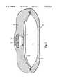
- FIG. 1represents a vertical section through a schematically depicted implantable infusion pump according to the invention.
- FIG. 2also depicts a vertical section of an additional schematically depicted implantable infusion pump.
- FIG. 3depicts a vertical section through a specially designed infusion pump for the dosed administration of medication into the human body.
- the object of this inventionto provide an implantable infusion pump with which gas diffusion (propellant on the one hand and gases and water vapor on the other) through the partition between the medication reservoir and the pressure chamber containing the propellant is essentially eliminated and a constant pumping rate of the medication is guaranteed for the entire operating time, which is compatible with medications, easily filled with medications, simple and safe to handle, made of biocompatible materials and of mutually compatible materials and which can be produced simply and cost effectively.
- this objectis accomplished in an infusion pump of the type mentioned in the introduction in that the gas impermeable flexible partition is a convex metal foil following the contour of the inner form of the upper chamber part.
- the metal foil used as a partitionis convex in accordance with its following of the contour of the inner form of the upper chamber part (and correspondingly of the lower chamber part) and flexible and free of stress.
- This convex, or dome-shaped, design of the foilmay be achieved in any suitable manner, for instance, in a deep drawing process where the foil is adapted to the inner shape of the upper chamber part (and correspondingly of the lower chamber part) of the housing of the infusion pump.
- the metal foilmay be made of any metal suitable for this purpose, whereby foils of aluminum, gold, silver, titanium or platinum are preferred. In particular, an aluminum foil is preferred.
- the thickness of the foilmust be such that the blocking effect is guaranteed and also that the foil will not buckle.
- the suitable thickness of the metal foilis in the range of 1-100 ⁇ m, preferably in the range of 3-40 ⁇ m and in particular in the range of 5-20 ⁇ m.
- the metal foilcan be provided with a coating of a polymer support film on the side facing the medication or the medicinal solution.
- a polyurethanemay be used as an adhesive.
- Polymer materials which possess good medication compatibility and also have good blocking characteristics against water vapor, oxygen and CO 2are suitable as supports.
- films made of polyethyleneterephthalateare preferred. The thickness of these films is suitably in the range of 1-100 ⁇ m, preferably 30-40 ⁇ m and in particular 5-20 ⁇ m and may, for example, be 12 ⁇ m.
- the metal foilcan be provided, according to the invention, with a coating of a support film on the side facing the propellant whereby, for example, suitably a polyurethane may be used as an adhesive.
- a support filmon the side facing the propellant
- polyurethanemay be used as an adhesive.
- Polymer materials which are compatible with the propellant and also provide good blocking characteristics against the propellantare suitable as supports.
- films made, for example, of polyolefins or polyamidesare suitable, whereby polyolefins are preferred.
- films made of polyethylene or polypropyleneare preferred, whereby films made of polyethylene are preferred in particular.
- the thickness of these filmsis suitably in the range of 2-400 ⁇ m, preferably 10-100 ⁇ m and in particular 25-100 ⁇ m and may, for example, be 70 ⁇ m.
- the metal foilcan be provided with a coating of a support lamination on both sides whereby the above mentioned films are each disposed on the appropriate side.
- the metal foil on the side facing the medicinal solutionmay be coated with a film of polyethyleneterephthalat and the one on the side facing the propellant with a polyolefine film, such as a polyethylene film.
- a lamination system--viewed from the medication reservoir--may preferably be structured as follows:
- metal foilpreferably aluminum foil, thickness 12 ⁇ m
- the polymer support filmsincrease the bending radii and thus reduce the tendency to buckle.
- the partitionmay be designed as a film system whereby on the side of the aforementioned metal foil or metal lamination foil facing the medicinal solution, a polymer film with good blocking characteristics against water vapor and/or a polymer film with good medication compatibility and blocking characteristics against water vapor, oxygen and CO 2 is additionally disposed, whereby, if the two additional films are present, the polymer film with good drug compatibility comes in contact with the medicinal solution, and the polymer film with good blocking characteristics against water vapor is disposed between the polymer film with good drug compatibility and the metal foil or metal composite film.
- both additional films for the metal, or metal composite filmare present.
- a polyethyleneterphthalat filmis particularly suitable.
- the thickness of these filmsis suitably in the range of 2-400 ⁇ m, preferably having a thickness of 25-250 ⁇ m and in particular within the range of 40-150 ⁇ m and may, for example, be 100 ⁇ m thick.
- any polymer film which has these characteristicsis suitable, whereby a polychlortrifluoroethylene film is particularly preferred.
- the thickness of these filmsis suitably in the range of 2-400 ⁇ m, preferably having a thickness of 25-250 ⁇ m and in particular within the range of 40-150 ⁇ m and may, for example, be 127 ⁇ m thick.
- the two additional filmsmay (if both are present) be connected with or glued to each other and to the metal foil or the metal composite film over the entire surface or only in the edge area, e.g., edge welded or glued, whereby the edge connection is preferred.
- a particularly preferred film system--seen from the medication reservoir--iscomposed as follows:
- metal foilpreferably aluminum foil
- polyolefin filmpreferably polyethylene film
- This film systemis also convex in accordance with its following the contour of the inner form of the upper chamber part (and correspondingly of the lower chamber part) and flexible and free of stress. This convex design of the film system is obtained in the already aforementioned manner.
- the partition usedis conventionally securely pressed or jammed in its edge area between the edge areas between the upper part of the chamber and the lower part of the chamber.
- a metal foil or a lamination metal film or a metal foil system as described abovemay be disposed within the infusion pump in addition to the above-described gas impermeable partition made of the metal foil or lamination metal foil or the aforementioned film system between the propellant and the inner wall of the lower part of the chamber.
- the metal foil or the metal lamination film or the film systemis convex following the contour of the inner form of the lower chamber part, whereby this convex design may be achieved in the previously described manner.
- This additional metal foil or the metal lamination film or the additional film systemis connected with the flexible gas impermeable partition used according to the invention in the edge area along the entire circumference, for example, by means of edge welding or glueing.
- pill-shaped structureserves as a pressure chamber to accommodate the propellant.
- This pill shaped pressure chamberis securely pressed or jammed in its edge area between the edge along its circumference--as previously described for the partition--between the edge areas of the upper part of the chamber and the lower part of the chamber.
- the sealing of the pressure chambermay take place in a suitable manner, such as by means of sealing rings made of a suitable material, such as elastomers, e.g. silicon-O-rings, or metals or by glueing with a suitable adhesive, e.g. with 2-component resins.
- a suitable materialsuch as elastomers, e.g. silicon-O-rings, or metals
- glueingwith a suitable adhesive, e.g. with 2-component resins.
- the filling of the pressure chamber with the propellantcan take place after removal of the existing air from the pressure chamber (e.g., by aspiration) in any suitable manner. It is possible, for example, to introduce a microcapillary through the sealing surface through which the propellant may be filled into the pressure chamber. After the filling with the propellant the capillary can be plugged or withdrawn.
- propellants that are usually used in implantable infusion pumpsmay serve as a propellant.
- the propellant hexafluorobutaneis used as a propellant according to the invention, whereby 1,1,1,4,4,4-hexafluorobutane is preferred in particular.
- Implantable infusion pumps containing these propellantsare described in the application simultaneously submitted with this application under file no. P 195 09 632.0-35 with the title "Implantable Infusion Pump" (Our reference FR2664)
- the implantable infusion pumps having the previously described flexible gas impermeable partition, or the "pill shaped" pressure chambermay be designed in any suitable manner and made of any suitable biocompatible material, such as, metal or plastic.
- theyare made of plastic, whereby hard plastics such as polysulphones (including polyethersulphones), polyamides and polycarbonates, in particular poly sulphones are preferred.
- hard plasticssuch as polysulphones (including polyethersulphones), polyamides and polycarbonates, in particular poly sulphones are preferred.
- infusion pumps made of plasticprovides substantial advantages. In addition to lower weight in comparison to infusion pumps made of metal, infusion pumps made of plastics provide the prerequisites for the simultaneous application of certain diagnostic procedures such as thermography and MRI.
- infusion pumpsare designed as described in DE 44 32 991 A1.
- the implantable infusion pump according to the inventionguarantees a constant pumping rate for the entire operational time. It has a low weight, is easy to, simple and safe to handle, and simple and cost effective to produce.
- the infusion pumpallows up to a maximum of 120 fillings with medicinal solutions whereby the pumping rates per day are, for example, 0.7, 1.0, 1.4, or 2.0 ml and the medication reservoir can accommodate approx. 30 ml of the medicinal solution.
- the amount of the propellant addedis small and may, for example, be 2 ml.
- the inner volume of the pressure chambermay be 40 ml, for example.
- the infusion pumpis suitable for the administration of a continuously dosed administration of medication such as e.g. heparin, artificial pancreatic insulin, chemotherapeutic agents, pain relievers, such as morphine, muscle relaxants, such as baclofen, and the like.
- medicationsuch as e.g. heparin, artificial pancreatic insulin, chemotherapeutic agents, pain relievers, such as morphine, muscle relaxants, such as baclofen, and the like.
- FIG. 1represents a vertical section through a schematically depicted implantable infusion pump according to the invention.
- the infusion pump 1is a disk shaped rotationally symmetric body made of hard plastic with a pump chamber which is formed by a lower part of the chamber 2 and the upper part of the chamber 3 and divided by a flexible gas impermeable partition 6 into two subchambers 7 and 8.
- the first subchamber 7serves as a medication reservoir and the second subchamber 8 serves as pressure chamber to accommodate the propellant.
- the refilling opening 12is sealingly covered by a pierceable central septum 13 and is provided beneath the central septum 13 with a refilling space with a fixed plate serving as a needle stop and a passage openings to the medication reservoir 7.
- the flexible gas impermeable partition 6is convex following the contour of the upper part of the chamber 3 (and accordingly the lower part of the chamber 2) which was achieved by deep drawing.
- This partitionis stress free. It consists of a film system which, seen from the medication reservoir 7, is composed as follows:
- the films of the aluminum composite filmare joined together by means of a polyurethane adhesive.
- the films a) and b)are joined together with the aluminum foil in the edge area along the entire circumference only.
- the partition 6is jammed or pressed between the edge areas of the upper chamber part 3 and the lower chamber part 2 with its outer edge area along its entire circumference.
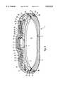
- FIG. 2also depicts a vertical section of an additional schematically depicted implantable infusion pump.
- This infusion pumpcorresponds to the infusion pump depicted in FIG. 1 according to example 1 with the exception that in addition to partition 6 a convex composite metal film P is also disposed.
- This composite metal film Pis made convex by deep drawing following the contour of the inner wall of the lower part of the chamber 2 and joined along the edges of the entire circumference of the partition 6 which has the same composition as the partition described according to example 1.
- the composite metal film P--seen from the pressure chamber 8--is composed as follows:
- a pill-shaped pressure chamber 8is formed by the partition 6 and the metal composite film P
- This pressure chamberis, as described in example 1, jammed or pressed between the edge areas of the upper chamber part 3 and the lower chamber part 2 with its edge area along its entire circumference.
- a propellant 1,1,1,4,4,4-hexafluorobutaneis used and is brought into the pressure chamber in that a microcapillary is introduced through the sealing surface in the edge area, the air removed from the pressure chamber and the pressure chamber filled with the propellant through the microcapillary.
- the amount introducedwas approx. 2 ml.
- the inner volume of the pressure chamber 8is approx. 40 ml and the medication reservoir can accommodate approx. 30 ml of the medicinal solution.
- FIG. 3depicts a vertical section through a specially designed infusion pump for the dosed administration of medication into the human body.
- the infusion pump 1is a disk shaped rotationally symmetric body made of polysulphone, with a housing that consists of a shell-shaped lower chamber part 2, an upper chamber part 3 executed in an opposing convex shape, a clasp 4 and a septum holder.
- the inner spaceis divided by a convex partition 6 and a likewise convex aluminum composite film P into a first subchamber serving as a medication reservoir 7 and a second subchamber serving as a pressure chamber 8 for the acceptance of the propellant.
- the pressure chamber 8is formed by welding or glueing of the edge of the partition 6 and the aluminum composite film and is shaped in the form of a pill.
- An annular grooveis molded at the upper inner edge area of the lower part of the chamber 2 into which groove!, as a snap-in joint, a circumferent corresponding edge 10 of the upper part of the chamber 3 together with an O-ring 11 and one edge 36 formed by the partition 6 and the aluminum composite film P is snapped and sealed.
- a refilling opening 12is sealingly covered by a pierceable central septum 13 and has, beneath the central septum 13, a refilling space with a fixed plate serving as a needle stop and passage openings to the medication reservoir 7.
- a concentric annular chamber 14which is sealingly covered by a ring septum 15, is molded.
- annular septum holder 5overlaps with its internal edge the edge of the disk shaped central septum 13 and with its external edge the inner edge of the ring of ring septum 15. Furthermore, septum holder 5 engages the annular groove 16 with the adjacent ring webs 19, 20, whereby the latches 21, 22 engage the snap-in grooves 17, 18 at the ring webs 19, 20.
- the annular outer edge of the ring septum 15is covered in a stepped arrangement by an appropriately shaped edge area of the clasp 4 and sealingly jammed against the upper chamber part 3. Furthermore, in this edge area of the clasp 4 a snap-in joint is provided between the clasp 4 and the upper chamber part 3 which joint! consists of a circumferent snapping groove 23 on the clasp 4 and a circumferent latch 24 on the upper chamber part 3.
- the latch 26represents the lower edge of the clasp 4, whereby said clasp overlaps the side area of the upper chamber part 3 and the external edge area on the side of the lower chamber part 2 in a bell shape.
- the clasp 4is supported (when stressed by high pressure) on the upper chamber part 3 by means of the latch arrangement 24 and by means of the annular septum 25 towards the lower chamber part 2.
- annular space 28is formed between the external wall area of the upper chamber part 3 and an inner wall area of clasp 4 to accommodate an outlet reduction arrangement 29 (here schematically depicted as a section through a capillary) and an outlet catheter 30.
- connection 31formed by the annular groove 9, the edge 10 and the O-ring 11, the connection 32, formed by the snapping groove 23 and the latch 24 as well as connection 33 consisting of snapping groove 18 and the latches 22 are the primary joints which essentially support the internal pressure stresses occurring from loads from normal operational use.
- connection 34consisting of annular groove 25, the latches 26 and the O-ring 27 as well as connection 35, consisting of the snapping groove 17 and the latches 21, are secondary joints which have no or at least a very slight support function under normal operational use.
- the secondary joints 34, 35provide support function by increased pressure above normal operational pressure only, in particular in the case of failure of the primary joints 31, 32, 33.
- the primary joints 31, 32, 33are hereby in constant engagement and ensure the integrity of the implanted infusion pump under normal operational conditions. With an increase of the internal pressure either in the annular space 28 or in the medication reservoir 7, the secondary joints 34, 35 increasingly engage. Hereby the stresses are transferred from the primary joints 31, 32, 33 and are distributed to primary and secondary joints.
- the connecting taskis taken over by the secondary joint 34. Since a gap simultaneously occurs between the upper chamber part 3 and the lower chamber part 2, medication escapes into the annular space 28 between the clasp 4 and the upper chamber part 3 thus causing the total pressure and thus the stress of the joint to decrease. This enables the secondary joint 34 to guarantee the integrity of the infusion pump to the outside. It is essential here that the lower part fail in the upper area of the latches but not in the lower part which can be secured by design.
- the partition 6 used in this examplecorrespond to the partition 6 and the aluminum composite film used in example 2 with regard to its composition as well as its shape.
- the pill shaped pressure chamber 8has an inner volume of 40 ml and contains approx. 2 ml of 1,1,1,4,4,4-hexafluorobutane as a propellant.
- the medication reservoircan accommodate up to 30 ml of medicinal solution. This infusion pump allows up to a maximum of 120 fillings with the medicinal solution and daily pumping rates of 0.7, 1.0, 1.4 or 2.0 ml of medicinal solution.
Landscapes
- Health & Medical Sciences (AREA)
- Vascular Medicine (AREA)
- Engineering & Computer Science (AREA)
- Anesthesiology (AREA)
- Biomedical Technology (AREA)
- Heart & Thoracic Surgery (AREA)
- Hematology (AREA)
- Life Sciences & Earth Sciences (AREA)
- Animal Behavior & Ethology (AREA)
- General Health & Medical Sciences (AREA)
- Public Health (AREA)
- Veterinary Medicine (AREA)
- Infusion, Injection, And Reservoir Apparatuses (AREA)
- Media Introduction/Drainage Providing Device (AREA)
Abstract
Description
Claims (16)
Applications Claiming Priority (2)
| Application Number | Priority Date | Filing Date | Title |
|---|---|---|---|
| DE19509634ADE19509634C1 (en) | 1995-03-17 | 1995-03-17 | Implantable infusion pump with constant delivery rate |
| DE19509634.7 | 1995-03-17 |
Publications (1)
| Publication Number | Publication Date |
|---|---|
| US5814019Atrue US5814019A (en) | 1998-09-29 |
Family
ID=7756904
Family Applications (1)
| Application Number | Title | Priority Date | Filing Date |
|---|---|---|---|
| US08/618,431Expired - LifetimeUS5814019A (en) | 1995-03-17 | 1996-03-15 | Implantable infusion pump |
Country Status (5)
| Country | Link |
|---|---|
| US (1) | US5814019A (en) |
| EP (1) | EP0732113B1 (en) |
| JP (1) | JP3895799B2 (en) |
| DE (2) | DE19509634C1 (en) |
| ES (1) | ES2165447T3 (en) |
Cited By (64)
| Publication number | Priority date | Publication date | Assignee | Title |
|---|---|---|---|---|
| US6139535A (en)* | 1999-05-27 | 2000-10-31 | Situs Corporation | Method and apparatus for placement and activation of a medical device within a body cavity |
| US6183461B1 (en) | 1998-03-11 | 2001-02-06 | Situs Corporation | Method for delivering a medication |
| US6264634B1 (en)* | 1997-07-25 | 2001-07-24 | Seiko Instruments Inc. | Implant type chemical supply device |
| US6280416B1 (en)* | 1999-02-19 | 2001-08-28 | Minimed Inc. | Constant flow medication infusion pump |
| US6283943B1 (en)* | 1999-02-19 | 2001-09-04 | Minimed Inc. | Negative pressure pump |
| USD461560S1 (en) | 2001-04-09 | 2002-08-13 | Medtronic, Inc. | Implantable therapeutic substance delivery device |
| US6589205B1 (en) | 1999-12-17 | 2003-07-08 | Advanced Bionica Corporation | Externally-controllable constant-flow medication delivery system |
| US20030208184A1 (en)* | 2000-01-11 | 2003-11-06 | Paul Burke | Implantable, refillable infusion device and spetum replacement kit |
| US6719739B2 (en)* | 2000-08-30 | 2004-04-13 | Medtronic, Inc. | System and method for attaching upper and lower outer cases in an implantable drug pump |
| US20040082908A1 (en)* | 2001-01-30 | 2004-04-29 | Whitehurst Todd K. | Microminiature infusion pump |
| US20050191194A1 (en)* | 2004-02-26 | 2005-09-01 | Falk Theodore J. | Low power electromagnetic pump having internal compliant element |
| US20060259016A1 (en)* | 2005-05-10 | 2006-11-16 | Palion Medical Corporation | Reduced size implantable pump |
| US20060259015A1 (en)* | 2005-05-10 | 2006-11-16 | Palion Medical Corporation | Implantable pump with infinitely variable resistor |
| US20060271021A1 (en)* | 2005-05-25 | 2006-11-30 | Palion Medical Corporation | Multi-reservoir implantable pump with patient controlled actuation |
| US20070043335A1 (en)* | 2005-07-22 | 2007-02-22 | Medtronic, Inc. | Miniature pump for drug delivery |
| US20070112328A1 (en)* | 2005-05-10 | 2007-05-17 | Palyon Medical Corporation | Variable flow infusion pump system |
| US20070117841A1 (en)* | 2003-10-24 | 2007-05-24 | Ozes Osman N | Use of pirfenidone in therapeutic regimens |
| RU2310449C1 (en)* | 2006-05-17 | 2007-11-20 | Руслан Геннадьевич Нервалев | Method for treating opioid and/or alcoholic addiction |
| US20080131398A1 (en)* | 2006-08-21 | 2008-06-05 | United Therapeutics Corporation | Combination therapy for treatment of viral infections |
| US20080171970A1 (en)* | 2006-11-01 | 2008-07-17 | Luzbetak Mark A | Self returning contamination barrier |
| US7708730B2 (en) | 2006-01-30 | 2010-05-04 | Palyon Medical (Bvi) Limited | Template system for multi-reservoir implantable pump |
| WO2010107739A2 (en) | 2009-03-18 | 2010-09-23 | The Board Of Trustees Of The Leland Stanford Junior University | Methods and compositions of treating a flaviviridae family viral infection |
| US20110106010A1 (en)* | 2009-10-30 | 2011-05-05 | Palyon Medical (Bvi) Limited | Propellant bag improvement |
| EP2390262A1 (en) | 2003-05-16 | 2011-11-30 | Intermune, Inc. | Synthetic chemokine receptor ligands and methods of use thereof |
| US8105269B2 (en) | 2008-10-24 | 2012-01-31 | Baxter International Inc. | In situ tubing measurements for infusion pumps |
| US8137083B2 (en) | 2009-03-11 | 2012-03-20 | Baxter International Inc. | Infusion pump actuators, system and method for controlling medical fluid flowrate |
| US8160695B2 (en) | 2007-12-05 | 2012-04-17 | The Invention Science Fund I, Llc | System for chemical modulation of neural activity |
| US8165668B2 (en) | 2007-12-05 | 2012-04-24 | The Invention Science Fund I, Llc | Method for magnetic modulation of neural conduction |
| US8165669B2 (en) | 2007-12-05 | 2012-04-24 | The Invention Science Fund I, Llc | System for magnetic modulation of neural conduction |
| US8170658B2 (en) | 2007-12-05 | 2012-05-01 | The Invention Science Fund I, Llc | System for electrical modulation of neural conduction |
| US8170659B2 (en) | 2007-12-05 | 2012-05-01 | The Invention Science Fund I, Llc | Method for thermal modulation of neural activity |
| US8180446B2 (en) | 2007-12-05 | 2012-05-15 | The Invention Science Fund I, Llc | Method and system for cyclical neural modulation based on activity state |
| US8180447B2 (en) | 2007-12-05 | 2012-05-15 | The Invention Science Fund I, Llc | Method for reversible chemical modulation of neural activity |
| US8195287B2 (en) | 2007-12-05 | 2012-06-05 | The Invention Science Fund I, Llc | Method for electrical modulation of neural conduction |
| WO2012175698A1 (en) | 2011-06-23 | 2012-12-27 | Université Libre de Bruxelles | Therapeutic use of all-trans retinoic acid (atra) in patients suffering from alcoholic liver disease |
| US8382447B2 (en) | 2009-12-31 | 2013-02-26 | Baxter International, Inc. | Shuttle pump with controlled geometry |
| US8398654B2 (en) | 2008-04-17 | 2013-03-19 | Allergan, Inc. | Implantable access port device and attachment system |
| US8409221B2 (en) | 2008-04-17 | 2013-04-02 | Allergan, Inc. | Implantable access port device having a safety cap |
| WO2013097957A1 (en) | 2011-12-28 | 2013-07-04 | Palyon Medical (Bvi) Limited | Programmable implantable pump design |
| WO2013097956A1 (en) | 2011-12-28 | 2013-07-04 | Palyon Medical (Bvi) Limited | Variable flow infusion pump system |
| US8506532B2 (en) | 2009-08-26 | 2013-08-13 | Allergan, Inc. | System including access port and applicator tool |
| US8567235B2 (en) | 2010-06-29 | 2013-10-29 | Baxter International Inc. | Tube measurement technique using linear actuator and pressure sensor |
| US8591456B2 (en) | 2011-12-28 | 2013-11-26 | Palyon Medical (Bvi) Limited | Multiple reservoir programmable pump |
| US8636693B2 (en) | 2011-04-27 | 2014-01-28 | Palyon Medical Corporation | Propellant pillow |
| US8708979B2 (en) | 2009-08-26 | 2014-04-29 | Apollo Endosurgery, Inc. | Implantable coupling device |
| US8715158B2 (en) | 2009-08-26 | 2014-05-06 | Apollo Endosurgery, Inc. | Implantable bottom exit port |
| US8801597B2 (en) | 2011-08-25 | 2014-08-12 | Apollo Endosurgery, Inc. | Implantable access port with mesh attachment rivets |
| US8821373B2 (en) | 2011-05-10 | 2014-09-02 | Apollo Endosurgery, Inc. | Directionless (orientation independent) needle injection port |
| WO2014159866A1 (en) | 2013-03-13 | 2014-10-02 | Palyon Medical Corporation | Dual rate insulin pump |
| US8858421B2 (en) | 2011-11-15 | 2014-10-14 | Apollo Endosurgery, Inc. | Interior needle stick guard stems for tubes |
| US8876771B2 (en) | 2010-11-16 | 2014-11-04 | Palyon Medical (Bvi) Limited | Propellant pillow manufacturing technique |
| US8882655B2 (en) | 2010-09-14 | 2014-11-11 | Apollo Endosurgery, Inc. | Implantable access port system |
| US8882728B2 (en) | 2010-02-10 | 2014-11-11 | Apollo Endosurgery, Inc. | Implantable injection port |
| US8905916B2 (en) | 2010-08-16 | 2014-12-09 | Apollo Endosurgery, Inc. | Implantable access port system |
| US8992415B2 (en) | 2010-04-30 | 2015-03-31 | Apollo Endosurgery, Inc. | Implantable device to protect tubing from puncture |
| US9089395B2 (en) | 2011-11-16 | 2015-07-28 | Appolo Endosurgery, Inc. | Pre-loaded septum for use with an access port |
| US9125718B2 (en) | 2010-04-30 | 2015-09-08 | Apollo Endosurgery, Inc. | Electronically enhanced access port for a fluid filled implant |
| US9192501B2 (en) | 2010-04-30 | 2015-11-24 | Apollo Endosurgery, Inc. | Remotely powered remotely adjustable gastric band system |
| US9199069B2 (en) | 2011-10-20 | 2015-12-01 | Apollo Endosurgery, Inc. | Implantable injection port |
| US9364484B2 (en) | 2011-12-06 | 2016-06-14 | The Board Of Trustees Of The Leland Stanford Junior University | Methods and compositions for treating viral diseases |
| US20170100548A1 (en)* | 2014-03-26 | 2017-04-13 | L.O.M. Laboratories Inc. | Gas release cell |
| US9737660B2 (en) | 2010-08-25 | 2017-08-22 | Medtronic, Inc. | Drug infusion device with controllable valve |
| US10143796B2 (en) | 2010-08-25 | 2018-12-04 | Medtronic, Inc. | Fluid delivery device refill access |
| US12296129B2 (en) | 2018-03-07 | 2025-05-13 | Soovu Labs, Inc. | Systems and methods for improved pain relief from stimulation of thermal fibers |
Families Citing this family (5)
| Publication number | Priority date | Publication date | Assignee | Title |
|---|---|---|---|---|
| US8808272B2 (en) | 1999-10-28 | 2014-08-19 | Boston Scientific Scimed, Inc. | Biocompatible medical devices |
| FI7960U1 (en)* | 2007-04-27 | 2008-07-28 | Bayer Schering Pharma Oy | Membrane shell for an implantable dosing system |
| DE102017120403B3 (en) | 2017-09-05 | 2018-08-23 | Tricumed Medizintechnik Gmbh | Infusion pump kit for the treatment of tumors |
| EP3501572A1 (en) | 2017-12-21 | 2019-06-26 | Luigi de Gaudenzi | Fluid supply device |
| CN111937835A (en)* | 2020-07-10 | 2020-11-17 | 北京农业智能装备技术研究中心 | Orchard wind bag type targeting sprayer and method based on ultrasonic sensing |
Citations (6)
| Publication number | Priority date | Publication date | Assignee | Title |
|---|---|---|---|---|
| US4969873A (en)* | 1988-06-23 | 1990-11-13 | Annemarie Schlogl Gesellschaft m.b.H. & Co., KG | Device for dispensing active substances to a patient |
| US5167633A (en)* | 1990-11-29 | 1992-12-01 | Pacesetter Infusion, Ltd. | Liquid-vapor pressure reservoir for medication infusion pump |
| US5306257A (en)* | 1992-05-04 | 1994-04-26 | Prime Medical Products, Inc. | Drug infuser |
| US5336194A (en)* | 1992-08-01 | 1994-08-09 | Fresenius Ag | Implantable apparatus |
| US5514103A (en)* | 1994-06-14 | 1996-05-07 | Minimed Inc. | Medication infusion pump with improved pressure reservoir |
| US5578005A (en)* | 1993-08-06 | 1996-11-26 | River Medical, Inc. | Apparatus and methods for multiple fluid infusion |
Family Cites Families (8)
| Publication number | Priority date | Publication date | Assignee | Title |
|---|---|---|---|---|
| FR2091189A5 (en)* | 1970-05-18 | 1972-01-14 | Regents University Minne | |
| US3951147A (en)* | 1975-04-07 | 1976-04-20 | Metal Bellows Company | Implantable infusate pump |
| US4573994A (en)* | 1979-04-27 | 1986-03-04 | The Johns Hopkins University | Refillable medication infusion apparatus |
| US4898582A (en)* | 1988-08-09 | 1990-02-06 | Pharmetrix Corporation | Portable infusion device assembly |
| DE3915251A1 (en)* | 1989-05-10 | 1990-11-22 | Annemarie Schloegl Ges M B H | IMPLANTABLE DEVICE FOR DISPENSING DISPOSAL OF MEDICINES IN HUMAN BODIES |
| DE4038049C2 (en)* | 1990-11-29 | 1994-12-01 | Anschuetz & Co Gmbh | Implantable infusion pump |
| DE4432991C1 (en)* | 1994-09-16 | 1995-10-26 | Fresenius Ag | Infusion pump for dispensing medicines into human body |
| DE19509632C1 (en)* | 1995-03-17 | 1996-03-28 | Fresenius Ag | Implantable infusion pump |
- 1995
- 1995-03-17DEDE19509634Apatent/DE19509634C1/ennot_activeExpired - Lifetime
- 1996
- 1996-03-13EPEP96103912Apatent/EP0732113B1/ennot_activeExpired - Lifetime
- 1996-03-13DEDE59608473Tpatent/DE59608473D1/ennot_activeExpired - Lifetime
- 1996-03-13ESES96103912Tpatent/ES2165447T3/ennot_activeExpired - Lifetime
- 1996-03-15USUS08/618,431patent/US5814019A/ennot_activeExpired - Lifetime
- 1996-03-18JPJP06142096Apatent/JP3895799B2/ennot_activeExpired - Fee Related
Patent Citations (6)
| Publication number | Priority date | Publication date | Assignee | Title |
|---|---|---|---|---|
| US4969873A (en)* | 1988-06-23 | 1990-11-13 | Annemarie Schlogl Gesellschaft m.b.H. & Co., KG | Device for dispensing active substances to a patient |
| US5167633A (en)* | 1990-11-29 | 1992-12-01 | Pacesetter Infusion, Ltd. | Liquid-vapor pressure reservoir for medication infusion pump |
| US5306257A (en)* | 1992-05-04 | 1994-04-26 | Prime Medical Products, Inc. | Drug infuser |
| US5336194A (en)* | 1992-08-01 | 1994-08-09 | Fresenius Ag | Implantable apparatus |
| US5578005A (en)* | 1993-08-06 | 1996-11-26 | River Medical, Inc. | Apparatus and methods for multiple fluid infusion |
| US5514103A (en)* | 1994-06-14 | 1996-05-07 | Minimed Inc. | Medication infusion pump with improved pressure reservoir |
Cited By (110)
| Publication number | Priority date | Publication date | Assignee | Title |
|---|---|---|---|---|
| US6264634B1 (en)* | 1997-07-25 | 2001-07-24 | Seiko Instruments Inc. | Implant type chemical supply device |
| US6183461B1 (en) | 1998-03-11 | 2001-02-06 | Situs Corporation | Method for delivering a medication |
| US6283943B1 (en)* | 1999-02-19 | 2001-09-04 | Minimed Inc. | Negative pressure pump |
| US6280416B1 (en)* | 1999-02-19 | 2001-08-28 | Minimed Inc. | Constant flow medication infusion pump |
| US6139535A (en)* | 1999-05-27 | 2000-10-31 | Situs Corporation | Method and apparatus for placement and activation of a medical device within a body cavity |
| US6589205B1 (en) | 1999-12-17 | 2003-07-08 | Advanced Bionica Corporation | Externally-controllable constant-flow medication delivery system |
| US20030208184A1 (en)* | 2000-01-11 | 2003-11-06 | Paul Burke | Implantable, refillable infusion device and spetum replacement kit |
| US6764472B1 (en) | 2000-01-11 | 2004-07-20 | Bard Access Systems, Inc. | Implantable refillable infusion device |
| US20040249363A1 (en)* | 2000-01-11 | 2004-12-09 | Bard Access Systems, Inc. | Implantable, refillable infusion device and septum replacement kit |
| US7108686B2 (en)* | 2000-01-11 | 2006-09-19 | Bard Access Systems, Inc. | Implantable, refillable infusion device and septum replacement kit |
| US6719739B2 (en)* | 2000-08-30 | 2004-04-13 | Medtronic, Inc. | System and method for attaching upper and lower outer cases in an implantable drug pump |
| AU2001286932B2 (en)* | 2000-08-30 | 2006-03-02 | Medtronic, Inc. | System and method for attaching upper and lower outer cases in an implantable drug pump |
| US20040082908A1 (en)* | 2001-01-30 | 2004-04-29 | Whitehurst Todd K. | Microminiature infusion pump |
| US7776029B2 (en) | 2001-01-30 | 2010-08-17 | The Alfred E. Mann Foundation For Scientific Research | Microminiature infusion pump |
| USD461560S1 (en) | 2001-04-09 | 2002-08-13 | Medtronic, Inc. | Implantable therapeutic substance delivery device |
| EP2390262A1 (en) | 2003-05-16 | 2011-11-30 | Intermune, Inc. | Synthetic chemokine receptor ligands and methods of use thereof |
| US20070117841A1 (en)* | 2003-10-24 | 2007-05-24 | Ozes Osman N | Use of pirfenidone in therapeutic regimens |
| US7407973B2 (en) | 2003-10-24 | 2008-08-05 | Intermune, Inc. | Use of pirfenidone in therapeutic regimens |
| US20050191194A1 (en)* | 2004-02-26 | 2005-09-01 | Falk Theodore J. | Low power electromagnetic pump having internal compliant element |
| US20060259016A1 (en)* | 2005-05-10 | 2006-11-16 | Palion Medical Corporation | Reduced size implantable pump |
| US20060259015A1 (en)* | 2005-05-10 | 2006-11-16 | Palion Medical Corporation | Implantable pump with infinitely variable resistor |
| US20070112328A1 (en)* | 2005-05-10 | 2007-05-17 | Palyon Medical Corporation | Variable flow infusion pump system |
| US8177750B2 (en) | 2005-05-10 | 2012-05-15 | Palyon Medical (Bvi) Limited | Variable flow infusion pump system |
| US8211060B2 (en)* | 2005-05-10 | 2012-07-03 | Palyon Medical (Bvi) Limited | Reduced size implantable pump |
| US8591478B2 (en) | 2005-05-10 | 2013-11-26 | Palyon Medical (Bvi) Limited | Reduced size implantable pump |
| US8915893B2 (en) | 2005-05-10 | 2014-12-23 | Palyon Medical (Bvi) Limited | Variable flow infusion pump system |
| US20070005044A1 (en)* | 2005-05-10 | 2007-01-04 | Palion Medical Corporation | Implantable pump with infinitely variable resistor |
| US7637892B2 (en) | 2005-05-10 | 2009-12-29 | Palyon Medical (Bvi) Limited | Variable flow infusion pump system |
| US20100069892A1 (en)* | 2005-05-10 | 2010-03-18 | Palyon Medical (Bvi) Limited | Variable flow infusion pump system |
| US8114055B2 (en)* | 2005-05-10 | 2012-02-14 | Palyon Medical (Bvi) Limited | Implantable pump with infinitely variable resistor |
| US20060271022A1 (en)* | 2005-05-25 | 2006-11-30 | Palion Medical Corporation | Multi-reservoir implantable pump with variable flow rate capabilities |
| US8034030B2 (en) | 2005-05-25 | 2011-10-11 | Palyon Medical (Bvi) Limited | Multi-reservoir implantable pump with variable flow rate capabilities |
| US20060271021A1 (en)* | 2005-05-25 | 2006-11-30 | Palion Medical Corporation | Multi-reservoir implantable pump with patient controlled actuation |
| US8034029B2 (en)* | 2005-05-25 | 2011-10-11 | Palyon Medical (Bvi) Limited | Multi-reservoir implantable pump with patient controlled actuation |
| US7931643B2 (en)* | 2005-07-22 | 2011-04-26 | Medtronic, Inc. | Miniature pump for drug delivery |
| US20070043335A1 (en)* | 2005-07-22 | 2007-02-22 | Medtronic, Inc. | Miniature pump for drug delivery |
| US20100160859A1 (en)* | 2006-01-30 | 2010-06-24 | Palyon Medical (Bvi) Limited | Template system for multi-reservoir implantable pump |
| US7914510B2 (en) | 2006-01-30 | 2011-03-29 | Palyon Medical (Bvi) Limited | Template system for multi-reservoir implantable pump |
| US7708730B2 (en) | 2006-01-30 | 2010-05-04 | Palyon Medical (Bvi) Limited | Template system for multi-reservoir implantable pump |
| RU2310449C1 (en)* | 2006-05-17 | 2007-11-20 | Руслан Геннадьевич Нервалев | Method for treating opioid and/or alcoholic addiction |
| US20080131398A1 (en)* | 2006-08-21 | 2008-06-05 | United Therapeutics Corporation | Combination therapy for treatment of viral infections |
| US9814809B2 (en) | 2006-11-01 | 2017-11-14 | Medela Holding Ag | Self returning contamination barrier |
| USD773643S1 (en) | 2006-11-01 | 2016-12-06 | Medela Holding Ag | Self returning contamination barrier |
| US20080171970A1 (en)* | 2006-11-01 | 2008-07-17 | Luzbetak Mark A | Self returning contamination barrier |
| US11642441B2 (en) | 2006-11-01 | 2023-05-09 | Medela Holding Ag | Self returning contamination barrier |
| US8187227B2 (en)* | 2006-11-01 | 2012-05-29 | Medela Holding Ag | Self returning contamination barrier |
| US8233976B2 (en) | 2007-12-05 | 2012-07-31 | The Invention Science Fund I, Llc | System for transdermal chemical modulation of neural activity |
| US9020591B2 (en) | 2007-12-05 | 2015-04-28 | The Invention Science Fund I, Llc | Method and system for ultrasonic neural modulation in a limb |
| US8180446B2 (en) | 2007-12-05 | 2012-05-15 | The Invention Science Fund I, Llc | Method and system for cyclical neural modulation based on activity state |
| US8180447B2 (en) | 2007-12-05 | 2012-05-15 | The Invention Science Fund I, Llc | Method for reversible chemical modulation of neural activity |
| US8170659B2 (en) | 2007-12-05 | 2012-05-01 | The Invention Science Fund I, Llc | Method for thermal modulation of neural activity |
| US8170658B2 (en) | 2007-12-05 | 2012-05-01 | The Invention Science Fund I, Llc | System for electrical modulation of neural conduction |
| US8195287B2 (en) | 2007-12-05 | 2012-06-05 | The Invention Science Fund I, Llc | Method for electrical modulation of neural conduction |
| US8165669B2 (en) | 2007-12-05 | 2012-04-24 | The Invention Science Fund I, Llc | System for magnetic modulation of neural conduction |
| US8165668B2 (en) | 2007-12-05 | 2012-04-24 | The Invention Science Fund I, Llc | Method for magnetic modulation of neural conduction |
| US9789315B2 (en) | 2007-12-05 | 2017-10-17 | Gearbox, Llc | Method and system for modulating neural activity |
| US8170660B2 (en) | 2007-12-05 | 2012-05-01 | The Invention Science Fund I, Llc | System for thermal modulation of neural activity |
| US8989858B2 (en) | 2007-12-05 | 2015-03-24 | The Invention Science Fund I, Llc | Implant system for chemical modulation of neural activity |
| US8630706B2 (en) | 2007-12-05 | 2014-01-14 | The Invention Science Fund I, Llc | Method and system for reversible chemical modulation of neural activity |
| US9358374B2 (en) | 2007-12-05 | 2016-06-07 | Gearbox, Llc | Method and system for blocking nerve conduction |
| US10092692B2 (en) | 2007-12-05 | 2018-10-09 | Gearbox, Llc | Method and system for modulating neural activity |
| US9014802B2 (en) | 2007-12-05 | 2015-04-21 | The Invention Science Fund I, Llc | Method and system for modulating neural activity in a limb |
| US8160695B2 (en) | 2007-12-05 | 2012-04-17 | The Invention Science Fund I, Llc | System for chemical modulation of neural activity |
| US9020592B2 (en) | 2007-12-05 | 2015-04-28 | The Invention Science Fund I, Llc | Method and system for blocking nerve conduction |
| US8409221B2 (en) | 2008-04-17 | 2013-04-02 | Allergan, Inc. | Implantable access port device having a safety cap |
| US9023063B2 (en) | 2008-04-17 | 2015-05-05 | Apollo Endosurgery, Inc. | Implantable access port device having a safety cap |
| US8398654B2 (en) | 2008-04-17 | 2013-03-19 | Allergan, Inc. | Implantable access port device and attachment system |
| US9023062B2 (en) | 2008-04-17 | 2015-05-05 | Apollo Endosurgery, Inc. | Implantable access port device and attachment system |
| US8105269B2 (en) | 2008-10-24 | 2012-01-31 | Baxter International Inc. | In situ tubing measurements for infusion pumps |
| US8496613B2 (en) | 2008-10-24 | 2013-07-30 | Baxter International Inc. | In situ tubing measurements for infusion pumps |
| US8137083B2 (en) | 2009-03-11 | 2012-03-20 | Baxter International Inc. | Infusion pump actuators, system and method for controlling medical fluid flowrate |
| WO2010107739A2 (en) | 2009-03-18 | 2010-09-23 | The Board Of Trustees Of The Leland Stanford Junior University | Methods and compositions of treating a flaviviridae family viral infection |
| US8715158B2 (en) | 2009-08-26 | 2014-05-06 | Apollo Endosurgery, Inc. | Implantable bottom exit port |
| US8708979B2 (en) | 2009-08-26 | 2014-04-29 | Apollo Endosurgery, Inc. | Implantable coupling device |
| US8506532B2 (en) | 2009-08-26 | 2013-08-13 | Allergan, Inc. | System including access port and applicator tool |
| US8753311B2 (en) | 2009-10-30 | 2014-06-17 | Palyon Medical (Bvi) Limited | Propellant bag improvement |
| US20110106010A1 (en)* | 2009-10-30 | 2011-05-05 | Palyon Medical (Bvi) Limited | Propellant bag improvement |
| US8231598B2 (en) | 2009-10-30 | 2012-07-31 | Palyon Medical (Bvi) Limited | Propellant bag improvement |
| US8382447B2 (en) | 2009-12-31 | 2013-02-26 | Baxter International, Inc. | Shuttle pump with controlled geometry |
| US8882728B2 (en) | 2010-02-10 | 2014-11-11 | Apollo Endosurgery, Inc. | Implantable injection port |
| US9192501B2 (en) | 2010-04-30 | 2015-11-24 | Apollo Endosurgery, Inc. | Remotely powered remotely adjustable gastric band system |
| US9125718B2 (en) | 2010-04-30 | 2015-09-08 | Apollo Endosurgery, Inc. | Electronically enhanced access port for a fluid filled implant |
| US8992415B2 (en) | 2010-04-30 | 2015-03-31 | Apollo Endosurgery, Inc. | Implantable device to protect tubing from puncture |
| US9241819B2 (en) | 2010-04-30 | 2016-01-26 | Apollo Endosurgery, Inc. | Implantable device to protect tubing from puncture |
| US8567235B2 (en) | 2010-06-29 | 2013-10-29 | Baxter International Inc. | Tube measurement technique using linear actuator and pressure sensor |
| US8905916B2 (en) | 2010-08-16 | 2014-12-09 | Apollo Endosurgery, Inc. | Implantable access port system |
| US11285258B2 (en) | 2010-08-25 | 2022-03-29 | Medtronic, Inc. | Fluid delivery device refill access |
| US10143796B2 (en) | 2010-08-25 | 2018-12-04 | Medtronic, Inc. | Fluid delivery device refill access |
| US9737660B2 (en) | 2010-08-25 | 2017-08-22 | Medtronic, Inc. | Drug infusion device with controllable valve |
| US8882655B2 (en) | 2010-09-14 | 2014-11-11 | Apollo Endosurgery, Inc. | Implantable access port system |
| US8876771B2 (en) | 2010-11-16 | 2014-11-04 | Palyon Medical (Bvi) Limited | Propellant pillow manufacturing technique |
| US8636693B2 (en) | 2011-04-27 | 2014-01-28 | Palyon Medical Corporation | Propellant pillow |
| US8821373B2 (en) | 2011-05-10 | 2014-09-02 | Apollo Endosurgery, Inc. | Directionless (orientation independent) needle injection port |
| WO2012175698A1 (en) | 2011-06-23 | 2012-12-27 | Université Libre de Bruxelles | Therapeutic use of all-trans retinoic acid (atra) in patients suffering from alcoholic liver disease |
| US8801597B2 (en) | 2011-08-25 | 2014-08-12 | Apollo Endosurgery, Inc. | Implantable access port with mesh attachment rivets |
| US9199069B2 (en) | 2011-10-20 | 2015-12-01 | Apollo Endosurgery, Inc. | Implantable injection port |
| US8858421B2 (en) | 2011-11-15 | 2014-10-14 | Apollo Endosurgery, Inc. | Interior needle stick guard stems for tubes |
| US9089395B2 (en) | 2011-11-16 | 2015-07-28 | Appolo Endosurgery, Inc. | Pre-loaded septum for use with an access port |
| US10869873B2 (en) | 2011-12-06 | 2020-12-22 | The Board Of Trustees Of The Leland Stanford Junior University | Methods and compositions for treating viral diseases |
| US9364484B2 (en) | 2011-12-06 | 2016-06-14 | The Board Of Trustees Of The Leland Stanford Junior University | Methods and compositions for treating viral diseases |
| US8591456B2 (en) | 2011-12-28 | 2013-11-26 | Palyon Medical (Bvi) Limited | Multiple reservoir programmable pump |
| US8808231B2 (en) | 2011-12-28 | 2014-08-19 | Palyon Medical (Bvi) Limited | Multiple reservoir programmable pump |
| WO2013097956A1 (en) | 2011-12-28 | 2013-07-04 | Palyon Medical (Bvi) Limited | Variable flow infusion pump system |
| WO2013097957A1 (en) | 2011-12-28 | 2013-07-04 | Palyon Medical (Bvi) Limited | Programmable implantable pump design |
| US8568360B2 (en) | 2011-12-28 | 2013-10-29 | Palyon Medical (Bvi) Limited | Programmable implantable pump design |
| US8961466B2 (en) | 2011-12-28 | 2015-02-24 | Palyon Medical (Bvi) Limited | Programmable implantable pump design |
| WO2014159866A1 (en) | 2013-03-13 | 2014-10-02 | Palyon Medical Corporation | Dual rate insulin pump |
| US10195364B2 (en)* | 2014-03-26 | 2019-02-05 | L.O.M. Laboratories Inc. | Gas release cell |
| US20170100548A1 (en)* | 2014-03-26 | 2017-04-13 | L.O.M. Laboratories Inc. | Gas release cell |
| US12296129B2 (en) | 2018-03-07 | 2025-05-13 | Soovu Labs, Inc. | Systems and methods for improved pain relief from stimulation of thermal fibers |
Also Published As
| Publication number | Publication date |
|---|---|
| ES2165447T3 (en) | 2002-03-16 |
| JP3895799B2 (en) | 2007-03-22 |
| EP0732113B1 (en) | 2001-12-19 |
| JPH08257140A (en) | 1996-10-08 |
| DE19509634C1 (en) | 1996-03-28 |
| EP0732113A1 (en) | 1996-09-18 |
| DE59608473D1 (en) | 2002-01-31 |
Similar Documents
| Publication | Publication Date | Title |
|---|---|---|
| US5814019A (en) | Implantable infusion pump | |
| US5722957A (en) | Implantable infusion pump | |
| EP0190477B1 (en) | Body mounted pump housing and pump assembly employing the same | |
| US6458102B1 (en) | External gas powered programmable infusion device | |
| US6852106B2 (en) | Implantable refillable and ported controlled release drug delivery device | |
| US4619652A (en) | Dosage form for use in a body mounted pump | |
| US5176641A (en) | Implantable drug infusion reservoir having fluid impelling resilient foam member | |
| JP3188689B2 (en) | Drug injection and dosing device | |
| US4258711A (en) | Infusion apparatus and method | |
| US4898582A (en) | Portable infusion device assembly | |
| US5885250A (en) | Fluid delivery device with conformable ullage | |
| FI92466B (en) | Artificial gland for implantation in human body | |
| EP0612535B2 (en) | Implantable infusion apparatus | |
| US5766150A (en) | Process for the filing of a propellant chamber of a gas driven pump | |
| JPS61268269A (en) | Manually operable embedddable apparatus for repeating and distributing administration amount of treating substance | |
| JPH07255843A (en) | Implantable injection system | |
| JPH0151268B2 (en) | ||
| JPH0341967A (en) | Gradual drug releasing device | |
| US20120191074A1 (en) | Reduced sized programmable pump | |
| KR101961415B1 (en) | Tubeless implantable drug infusion system | |
| JPS61176360A (en) | Body mounting pump housing and pump assembly using the same | |
| JP2807698B2 (en) | Implantable liquid injector | |
| CA1245930A (en) | Body mounted pump housing and pump assembly employing the same |
Legal Events
| Date | Code | Title | Description |
|---|---|---|---|
| AS | Assignment | Owner name:FRESENIUS AG, GERMANY Free format text:ASSIGNMENT OF ASSIGNORS INTEREST;ASSIGNORS:STEINBACH, BERND;WALTER, CLAUS;REEL/FRAME:008016/0403;SIGNING DATES FROM 19960508 TO 19960509 | |
| STCF | Information on status: patent grant | Free format text:PATENTED CASE | |
| FEPP | Fee payment procedure | Free format text:PAYOR NUMBER ASSIGNED (ORIGINAL EVENT CODE: ASPN); ENTITY STATUS OF PATENT OWNER: SMALL ENTITY | |
| FPAY | Fee payment | Year of fee payment:4 | |
| FEPP | Fee payment procedure | Free format text:PAYOR NUMBER ASSIGNED (ORIGINAL EVENT CODE: ASPN); ENTITY STATUS OF PATENT OWNER: SMALL ENTITY Free format text:PAYER NUMBER DE-ASSIGNED (ORIGINAL EVENT CODE: RMPN); ENTITY STATUS OF PATENT OWNER: SMALL ENTITY | |
| AS | Assignment | Owner name:INTERCEPT BIOMEDICAL (BVI) LIMITED, VIRGIN ISLANDS Free format text:ASSIGNMENT OF ASSIGNORS INTEREST;ASSIGNOR:FRESENIUS HEMOCARE DEUTSCHLAND GMBH;REEL/FRAME:015541/0447 Effective date:20041229 | |
| AS | Assignment | Owner name:FRESENIUS HEMOCARE DEUTSCHLAND GMBH, GERMANY Free format text:ASSIGNMENT OF ASSIGNORS INTEREST;ASSIGNOR:FRESENIUS AG;REEL/FRAME:016016/0778 Effective date:20050218 | |
| FEPP | Fee payment procedure | Free format text:PAT HOLDER CLAIMS SMALL ENTITY STATUS, ENTITY STATUS SET TO SMALL (ORIGINAL EVENT CODE: LTOS); ENTITY STATUS OF PATENT OWNER: SMALL ENTITY | |
| FPAY | Fee payment | Year of fee payment:8 | |
| AS | Assignment | Owner name:PALION MEDICAL (BVI) LIMITED, VIRGIN ISLANDS, BRIT Free format text:CHANGE OF NAME;ASSIGNOR:INTERCEPT BIOMEDICAL (BVI) LIMITED;REEL/FRAME:017492/0036 Effective date:20050311 | |
| AS | Assignment | Owner name:PALYON MEDICAL (BVI) LIMITED, VIRGIN ISLANDS, BRIT Free format text:CHANGE OF NAME;ASSIGNOR:PALION MEDICAL (BVI) LIMITED;REEL/FRAME:018635/0958 Effective date:20061110 | |
| FPAY | Fee payment | Year of fee payment:12 | |
| FEPP | Fee payment procedure | Free format text:PAYOR NUMBER ASSIGNED (ORIGINAL EVENT CODE: ASPN); ENTITY STATUS OF PATENT OWNER: SMALL ENTITY Free format text:PAYER NUMBER DE-ASSIGNED (ORIGINAL EVENT CODE: RMPN); ENTITY STATUS OF PATENT OWNER: SMALL ENTITY | |
| AS | Assignment | Owner name:AQULINX MEDICAL, CALIFORNIA Free format text:ASSIGNMENT OF ASSIGNORS INTEREST;ASSIGNOR:PALYON MEDICAL;REEL/FRAME:042312/0069 Effective date:20170404 |