US5813751A - Device for permanent installation of christmas lighting - Google Patents
Device for permanent installation of christmas lightingDownload PDFInfo
- Publication number
- US5813751A US5813751AUS08/784,031US78403197AUS5813751AUS 5813751 AUS5813751 AUS 5813751AUS 78403197 AUS78403197 AUS 78403197AUS 5813751 AUS5813751 AUS 5813751A
- Authority
- US
- United States
- Prior art keywords
- wall
- channel
- christmas
- front wall
- recess
- Prior art date
- Legal status (The legal status is an assumption and is not a legal conclusion. Google has not performed a legal analysis and makes no representation as to the accuracy of the status listed.)
- Expired - Fee Related
Links
Images


Classifications
- F—MECHANICAL ENGINEERING; LIGHTING; HEATING; WEAPONS; BLASTING
- F21—LIGHTING
- F21V—FUNCTIONAL FEATURES OR DETAILS OF LIGHTING DEVICES OR SYSTEMS THEREOF; STRUCTURAL COMBINATIONS OF LIGHTING DEVICES WITH OTHER ARTICLES, NOT OTHERWISE PROVIDED FOR
- F21V11/00—Screens not covered by groups F21V1/00, F21V3/00, F21V7/00 or F21V9/00
- F21V11/08—Screens not covered by groups F21V1/00, F21V3/00, F21V7/00 or F21V9/00 using diaphragms containing one or more apertures
- F21V11/14—Screens not covered by groups F21V1/00, F21V3/00, F21V7/00 or F21V9/00 using diaphragms containing one or more apertures with many small apertures
- F—MECHANICAL ENGINEERING; LIGHTING; HEATING; WEAPONS; BLASTING
- F21—LIGHTING
- F21S—NON-PORTABLE LIGHTING DEVICES; SYSTEMS THEREOF; VEHICLE LIGHTING DEVICES SPECIALLY ADAPTED FOR VEHICLE EXTERIORS
- F21S4/00—Lighting devices or systems using a string or strip of light sources
- F21S4/10—Lighting devices or systems using a string or strip of light sources with light sources attached to loose electric cables, e.g. Christmas tree lights
- F—MECHANICAL ENGINEERING; LIGHTING; HEATING; WEAPONS; BLASTING
- F21—LIGHTING
- F21V—FUNCTIONAL FEATURES OR DETAILS OF LIGHTING DEVICES OR SYSTEMS THEREOF; STRUCTURAL COMBINATIONS OF LIGHTING DEVICES WITH OTHER ARTICLES, NOT OTHERWISE PROVIDED FOR
- F21V15/00—Protecting lighting devices from damage
- F21V15/01—Housings, e.g. material or assembling of housing parts
- F—MECHANICAL ENGINEERING; LIGHTING; HEATING; WEAPONS; BLASTING
- F21—LIGHTING
- F21V—FUNCTIONAL FEATURES OR DETAILS OF LIGHTING DEVICES OR SYSTEMS THEREOF; STRUCTURAL COMBINATIONS OF LIGHTING DEVICES WITH OTHER ARTICLES, NOT OTHERWISE PROVIDED FOR
- F21V17/00—Fastening of component parts of lighting devices, e.g. shades, globes, refractors, reflectors, filters, screens, grids or protective cages
- F21V17/10—Fastening of component parts of lighting devices, e.g. shades, globes, refractors, reflectors, filters, screens, grids or protective cages characterised by specific fastening means or way of fastening
- F21V17/16—Fastening of component parts of lighting devices, e.g. shades, globes, refractors, reflectors, filters, screens, grids or protective cages characterised by specific fastening means or way of fastening by deformation of parts; Snap action mounting
- F—MECHANICAL ENGINEERING; LIGHTING; HEATING; WEAPONS; BLASTING
- F21—LIGHTING
- F21V—FUNCTIONAL FEATURES OR DETAILS OF LIGHTING DEVICES OR SYSTEMS THEREOF; STRUCTURAL COMBINATIONS OF LIGHTING DEVICES WITH OTHER ARTICLES, NOT OTHERWISE PROVIDED FOR
- F21V27/00—Cable-stowing arrangements structurally associated with lighting devices, e.g. reels
- F—MECHANICAL ENGINEERING; LIGHTING; HEATING; WEAPONS; BLASTING
- F21—LIGHTING
- F21W—INDEXING SCHEME ASSOCIATED WITH SUBCLASSES F21K, F21L, F21S and F21V, RELATING TO USES OR APPLICATIONS OF LIGHTING DEVICES OR SYSTEMS
- F21W2121/00—Use or application of lighting devices or systems for decorative purposes, not provided for in codes F21W2102/00 – F21W2107/00
- F21W2121/004—Use or application of lighting devices or systems for decorative purposes, not provided for in codes F21W2102/00 – F21W2107/00 mounted on the exterior of houses or other buildings to illuminate parts thereof
- Y—GENERAL TAGGING OF NEW TECHNOLOGICAL DEVELOPMENTS; GENERAL TAGGING OF CROSS-SECTIONAL TECHNOLOGIES SPANNING OVER SEVERAL SECTIONS OF THE IPC; TECHNICAL SUBJECTS COVERED BY FORMER USPC CROSS-REFERENCE ART COLLECTIONS [XRACs] AND DIGESTS
- Y10—TECHNICAL SUBJECTS COVERED BY FORMER USPC
- Y10S—TECHNICAL SUBJECTS COVERED BY FORMER USPC CROSS-REFERENCE ART COLLECTIONS [XRACs] AND DIGESTS
- Y10S362/00—Illumination
- Y10S362/806—Ornamental or decorative
Definitions
- the present inventionpertains generally to decorative Christmas lighting displays, and more particularly to devices for permanent installation of Christmas lighting on the exteriors of buildings and other structures.
- KvardaU.S. Pat. No. 3,204,090, disclosed a channel-shaped holder mountable on a building exterior and capable of holding a string of decorative lights, wherein the wiring and sockets were retained in the channel and the lamps were exposed in a straight line exteriorly of the channel. No provision was made, however, for removing the lamps from view after the end of the Christmas holiday season short of taking down the entire holder.
- a second approach to overcoming these problemshas been to provide a Christmas lighting fixture unit having a housing adapted for mounting on a building, the housing having an opening in a wall on which a door is mounted for movement between open and closed positions. Electric lights were swingable between a hidden position inside the housing and an exposed position extending through the opening. See, e.g., Konecny, U.S. Pat. No. 5,510,966, and Robinson, U.S. Pat. No. 3,692,993. Similarly, Branham, U.S. Pat. No.
- 5,311,414provided an elongated housing structure, the housing having a hinged cover plate movable from a position that covered the light bulbs contained within the structure to a position that exposed the bulbs to view; see also, Premetz, U.S. Pat. No. 4,128,863.
- Another variation on this themewas provided by Wood, U.S. Pat. No. 5,404,279, who disclosed a flip open decorative hidden light trim assembly for permanent installation along the trim line of a house.
- the assemblyincluded a series of linearly interconnected trim members having a hollow body containing lights and an openable reflective cover member.
- a device for permanent installation of a string of Christmas lights on an exterior surface of a building or structureincludes an elongated channel and channel recess defined by horizontal top and bottom walls joined by a vertical rear wall, and a front wall depending downwards from the top wall.
- the rear wallhas a height greater than the height of the front wall
- the top wallhas a depth greater than the depth of the bottom wall. Consequently, the channel has an elongated gap between the front and bottom walls.
- the devicefurther includes a flexible, rectangular screen having a length equal to the length of the channel recess and having a width sufficient to span the gap and for the screen to be received and retained between the front and the bottom walls.
- a string of Christmas lightsis laid within the recess with the lamps facing toward and visible through the screen and extending from one end of the channel to an opposite end. Thereafter, the screen is flexed sufficiently to place it between the bottom and front walls, the device is attached to an exterior surface of a building and connected to electrical power.
- a plurality of horizontally spaced-apart lamp sockets, connected by electrical wiring,are attached to an inner surface of the channel and oriented so that lamps inserted into the sockets face toward the gap and are visible when lit through the cover screen.
- Important objectives of the present inventioninclude the provision of an elongate device for use in conjunction with additional such devices for permanently installing Christmas lighting on an exterior surface of a building; the minimal marring of said exterior surface due to the installation; the provision of a flexible, easily removed cover screen for the device to facilitate replacing burned out Christmas light bulbs; the provision of such an elongate device that is easily cut or mitered for custom fit to a building exterior, having few parts, simple in design, durable against the elements, and inexpensive to manufacture.
- FIG. 1is a front elevational view of a house with the device permanently installed along principal architectural features thereof;
- FIG. 2is a front elevational view of the device showing the removable cover screen placed between the front wall and the bottom wall of the device;
- FIG. 3shows a left end portion of the device in enlarged, frontal perspective view, with a part of the cover screen cut away;
- FIG. 4is an enlarged, front elevational view of two of the devices in angled, abutting engagement as they would appear, for example, adjacent the peak of a pitched roof;
- FIG. 5is an enlarged, side elevational view of a left end of the device
- FIG. 6Ais an elevational view of a left end cap of the device
- FIG. 6Bis a rear elevational view of a left end cap
- FIG. 7Ais an elevational view of a right end cap of the device
- FIG. 7Bis a rear elevational view of a right end cap
- FIG. 8is a perspective view of the device being attached to house eaves
- FIG. 9is a right end view of the device attached by a J hanger to a rear surface of a vertical wall
- FIG. 10is an enlarged perspective view of a J hanger
- FIG. 11is a front plan view with the cover screen removed showing a string of Christmas lights installed in the device.
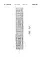
- FIG. 12is a front plan view of an alternate embodiment of the device with the cover screen removed and showing bulb sockets incorporated into a rear wall of the device.
- FIG. 13is a frontal perspective view of the cover screen removed from the device.
- FIG. 1a preferred embodiment of the device, denoted generally by the numeral 10, is shown permanently installed on the exterior of a house 12.
- the device 10is depicted attached to principal architectural features of the house exterior 12, including the eaves 14, the edges 16 of the pitched roof 18, and the entry way roof 20, and is designed to visually blend in with the appearance of the house exterior 12.
- FIGS. 2 and 5it may be seen that the device 10 comprises a horizontal top wall 30 and a horizontal bottom wall 32 joined by a vertical rear wall 34, and a front wall 36 that depends from the top wall 30.
- the top wall 30has a depth greater than the depth of the bottom wall 32, preferably by a factor of two or more.
- the rear wall 34has a height greater than the height of the front wall 36, preferably by a factor of two or more.
- the rear wall 34has height 2.5 inches
- the top wall 30has depth 2.5 inches
- the bottom wall 32has depth 1.0 inch
- the front wall 36has height 1.0 inch.
- Each of the walls 30, 32, 34, 36is horizontally and equally elongated, thereby defining an elongated channel, denoted generally by the numeral 38, and a channel recess 40, said channel recess 40 being the space partially surrounded by the channel 38.
- the walls 30, 32, 34, 36 of the channel 38may be formed from any suitably rigid, durable and weather-resistant material, e.g., aluminum or galvanized steel, but polypropylene plastic such as that commonly used in rain gutters and downspouts is preferred. Plastic used for this purpose should be ultraviolet light protected, however, by methods well known to those of ordinary skill in the art, because, if it is not so protected, exposure to the sun will cause the material to become brittle.
- the device 10further comprises a flexible, rectangular cover screen 50 having an upper edge 51 and a lower edge 53.
- the cover screen 50is preferably formed from polypropylene plastic, and has a plurality of openings 52 that permit viewing illuminated decorative light bulbs 61 within the channel recess 40 when the cover screen 50 is inserted and retained between the front wall 36 and the bottom wall 32.
- the cover screen 50when so inserted the cover screen 50 is curvilinearly flexed and thus, with a slight bending, the cover screen 50 may be easily inserted into, and removed from, the channel 38.
- a suitable plastic screen for this purposeis screen number 9180 manufactured by Bemis Corporation of Sheboygan Falls, Wisc.
- the rear wall 34 and front wall 36are provided with a plurality of horizontally spaced-apart screw holes 60 for mounting the channel 38 to a surface with screws 70, for example, a vertical surface.
- Ample access for a screw driver 80is available with the cover screen 50 removed for such an installation.
- screw driver access holes 64are provided in the rear wall 34 in register with screw holes 60 in the front wall 36.
- each J hanger 110For attachment to a rear vertical surface 100 cantilevered out from a building, as shown for example in FIG. 9, a plurality of J hangers 110 may be attached by fasteners (e.g., screws) to said surface 100, and a front wall 36 of the channel 38 may be inserted into and supported by the J hangers 110. As shown in FIG. 10, each J hanger 110 is a band of resilient metal or plastic folded back on itself and crimped.
- Adjacent the peak 120 of a pitched roof, the abutting ends of two of the devices 10may be mitered for a custom fit as shown in FIG. 4.
- a string of decorative lightsdenoted generally by the numeral 140, comprising a linear series of decorative light bulb sockets 150 and light bulbs 61 connected by electrical wiring 160, a male plug 170 at one end, and a female plug 180 at an opposite end, is placed within the channel recess 40, stretching from a left end 52 to a right end 54 thereof.
- a cord clamp 80is provided for securing the electrical wiring 160 to the rear wall 34.
- the dimensions of the channel 38should be suitably adjusted in this embodiment to provide adequate clearance and heat dissipation for the bulb sockets and bulbs.
- each end capcomprises a flat plate portion 190 and a lip 192 projecting from one side thereof shaped to conform to the channel 38 as seen in end view, as shown for example in FIG. 5.
- the channel 38may be formed by plastic injection molding or by extrusion.
- aluminum or polypropylene tubing of square cross sectionsuch as those commonly used for rain downspouts can be cut longitudinally to eliminate one corner and part of the sides thereof adjacent to the corner to achieve the desired channel cross-section illustrated in FIG. 5.
- a plurality of horizontally spaced-apart decorative light bulb sockets 150are affixed to an interior surface of the channel 38, as shown in FIG. 12, connected one to the next by electrical wiring (not shown), with a male plug 170 connected to one end and a female plug 180 connected to an opposite end.
- the sockets 150may be an integral, molded part of the channel 38; alternatively, the sockets 150 may be affixed to the channel 38 by fasteners or adhesive.
Landscapes
- Engineering & Computer Science (AREA)
- General Engineering & Computer Science (AREA)
- Non-Portable Lighting Devices Or Systems Thereof (AREA)
Abstract
Description
1. Field of the Invention
The present invention pertains generally to decorative Christmas lighting displays, and more particularly to devices for permanent installation of Christmas lighting on the exteriors of buildings and other structures.
2. Related Application
The applicant filed a provisional application for the invention on Jul. 1, 1996, application Ser. No. 60,020,529.
During the Christmas holiday season, many people attach exposed strings of decorative lights to the exterior surfaces of their homes and other buildings, which they take down and place in storage some time following New Year's Day. Undesirable consequences of this annual ritual include injuries due to falls from ladders, damage to the strings of decorative lights due to repeated handling, and marring of the exterior surfaces from repeated insertion and removal of fasteners. On the other hand, leaving such strings of lights on building exterior surfaces year-round is aesthetically undesirable, and the lights are subject to deterioration from exposure to the elements.
In one approach to overcoming some of these problems, Kvarda, U.S. Pat. No. 3,204,090, disclosed a channel-shaped holder mountable on a building exterior and capable of holding a string of decorative lights, wherein the wiring and sockets were retained in the channel and the lamps were exposed in a straight line exteriorly of the channel. No provision was made, however, for removing the lamps from view after the end of the Christmas holiday season short of taking down the entire holder.
A second approach to overcoming these problems has been to provide a Christmas lighting fixture unit having a housing adapted for mounting on a building, the housing having an opening in a wall on which a door is mounted for movement between open and closed positions. Electric lights were swingable between a hidden position inside the housing and an exposed position extending through the opening. See, e.g., Konecny, U.S. Pat. No. 5,510,966, and Robinson, U.S. Pat. No. 3,692,993. Similarly, Branham, U.S. Pat. No. 5,311,414, provided an elongated housing structure, the housing having a hinged cover plate movable from a position that covered the light bulbs contained within the structure to a position that exposed the bulbs to view; see also, Premetz, U.S. Pat. No. 4,128,863. Another variation on this theme was provided by Wood, U.S. Pat. No. 5,404,279, who disclosed a flip open decorative hidden light trim assembly for permanent installation along the trim line of a house. The assembly included a series of linearly interconnected trim members having a hollow body containing lights and an openable reflective cover member. These approaches to the above-outlined problems with exterior decorative Christmas lighting, however, require the manufacture of relatively complex and numerous components to achieve the desired results.
There remains, therefore, a need for a relatively simple and inexpensive device for permanent installation of decorative Christmas lighting that achieves the desired results.
According to the present invention, there is provided a device for permanent installation of a string of Christmas lights on an exterior surface of a building or structure. The device includes an elongated channel and channel recess defined by horizontal top and bottom walls joined by a vertical rear wall, and a front wall depending downwards from the top wall. The rear wall has a height greater than the height of the front wall, and the top wall has a depth greater than the depth of the bottom wall. Consequently, the channel has an elongated gap between the front and bottom walls. The device further includes a flexible, rectangular screen having a length equal to the length of the channel recess and having a width sufficient to span the gap and for the screen to be received and retained between the front and the bottom walls. In a first embodiment, with the cover screen removed, a string of Christmas lights is laid within the recess with the lamps facing toward and visible through the screen and extending from one end of the channel to an opposite end. Thereafter, the screen is flexed sufficiently to place it between the bottom and front walls, the device is attached to an exterior surface of a building and connected to electrical power. In an alternative embodiment, a plurality of horizontally spaced-apart lamp sockets, connected by electrical wiring, are attached to an inner surface of the channel and oriented so that lamps inserted into the sockets face toward the gap and are visible when lit through the cover screen.
Important objectives of the present invention include the provision of an elongate device for use in conjunction with additional such devices for permanently installing Christmas lighting on an exterior surface of a building; the minimal marring of said exterior surface due to the installation; the provision of a flexible, easily removed cover screen for the device to facilitate replacing burned out Christmas light bulbs; the provision of such an elongate device that is easily cut or mitered for custom fit to a building exterior, having few parts, simple in design, durable against the elements, and inexpensive to manufacture.
FIG. 1 is a front elevational view of a house with the device permanently installed along principal architectural features thereof;
FIG. 2 is a front elevational view of the device showing the removable cover screen placed between the front wall and the bottom wall of the device;
FIG. 3 shows a left end portion of the device in enlarged, frontal perspective view, with a part of the cover screen cut away;
FIG. 4 is an enlarged, front elevational view of two of the devices in angled, abutting engagement as they would appear, for example, adjacent the peak of a pitched roof;
FIG. 5 is an enlarged, side elevational view of a left end of the device;
FIG. 6A is an elevational view of a left end cap of the device;
FIG. 6B is a rear elevational view of a left end cap;
FIG. 7A is an elevational view of a right end cap of the device;
FIG. 7B is a rear elevational view of a right end cap;
FIG. 8 is a perspective view of the device being attached to house eaves;
FIG. 9 is a right end view of the device attached by a J hanger to a rear surface of a vertical wall;
FIG. 10 is an enlarged perspective view of a J hanger;
FIG. 11 is a front plan view with the cover screen removed showing a string of Christmas lights installed in the device; and
FIG. 12 is a front plan view of an alternate embodiment of the device with the cover screen removed and showing bulb sockets incorporated into a rear wall of the device.
FIG. 13 is a frontal perspective view of the cover screen removed from the device.
The terms "left," "right," "front," "rear," "top," bottom," "horizontal" and "vertical" shall be understood as referring to thedevice 10 as oriented and depicted in FIG. 2.
Referring now to FIG. 1, a preferred embodiment of the device, denoted generally by thenumeral 10, is shown permanently installed on the exterior of ahouse 12. Thedevice 10 is depicted attached to principal architectural features of thehouse exterior 12, including the eaves 14, theedges 16 of the pitched roof 18, and theentry way roof 20, and is designed to visually blend in with the appearance of thehouse exterior 12. Referring now to FIGS. 2 and 5, it may be seen that thedevice 10 comprises a horizontaltop wall 30 and ahorizontal bottom wall 32 joined by a verticalrear wall 34, and afront wall 36 that depends from thetop wall 30. Thetop wall 30 has a depth greater than the depth of thebottom wall 32, preferably by a factor of two or more. Therear wall 34 has a height greater than the height of thefront wall 36, preferably by a factor of two or more. For Christmas light strings of size C-7, preferably therear wall 34 has height 2.5 inches, thetop wall 30 has depth 2.5 inches, thebottom wall 32 has depth 1.0 inch and thefront wall 36 has height 1.0 inch. Each of thewalls channel recess 40, saidchannel recess 40 being the space partially surrounded by thechannel 38. Thewalls channel 38 may be formed from any suitably rigid, durable and weather-resistant material, e.g., aluminum or galvanized steel, but polypropylene plastic such as that commonly used in rain gutters and downspouts is preferred. Plastic used for this purpose should be ultraviolet light protected, however, by methods well known to those of ordinary skill in the art, because, if it is not so protected, exposure to the sun will cause the material to become brittle.
Referring to FIGS. 2-5, and 13, thedevice 10 further comprises a flexible,rectangular cover screen 50 having an upper edge 51 and alower edge 53. Thecover screen 50 is preferably formed from polypropylene plastic, and has a plurality ofopenings 52 that permit viewing illuminateddecorative light bulbs 61 within thechannel recess 40 when thecover screen 50 is inserted and retained between thefront wall 36 and thebottom wall 32. As may best be seen in FIG. 5, when so inserted thecover screen 50 is curvilinearly flexed and thus, with a slight bending, thecover screen 50 may be easily inserted into, and removed from, thechannel 38. When thecover screen 50 is removed from the device it assumes the unflexed, rectangular appearance shown in FIG. 13. A suitable plastic screen for this purpose is screen number 9180 manufactured by Bemis Corporation of Sheboygan Falls, Wisc.
As shown in FIGS. 3 and 4, therear wall 34 andfront wall 36 are provided with a plurality of horizontally spaced-apart screw holes 60 for mounting thechannel 38 to a surface withscrews 70, for example, a vertical surface. Ample access for ascrew driver 80 is available with thecover screen 50 removed for such an installation. As shown in FIG. 8, however, to attach afront wall 36 of thechannel 38 to an eave, screw driver access holes 64 are provided in therear wall 34 in register with screw holes 60 in thefront wall 36.
For attachment to a rearvertical surface 100 cantilevered out from a building, as shown for example in FIG. 9, a plurality ofJ hangers 110 may be attached by fasteners (e.g., screws) to saidsurface 100, and afront wall 36 of thechannel 38 may be inserted into and supported by the J hangers 110. As shown in FIG. 10, eachJ hanger 110 is a band of resilient metal or plastic folded back on itself and crimped.
Adjacent thepeak 120 of a pitched roof, the abutting ends of two of thedevices 10 may be mitered for a custom fit as shown in FIG. 4.
Referring to FIGS. 3 and 11, with thecover screen 50 removed, a string of decorative lights, denoted generally by the numeral 140, comprising a linear series of decorativelight bulb sockets 150 andlight bulbs 61 connected byelectrical wiring 160, amale plug 170 at one end, and afemale plug 180 at an opposite end, is placed within thechannel recess 40, stretching from aleft end 52 to aright end 54 thereof. Acord clamp 80 is provided for securing theelectrical wiring 160 to therear wall 34. The dimensions of thechannel 38 should be suitably adjusted in this embodiment to provide adequate clearance and heat dissipation for the bulb sockets and bulbs.
Except where aright end 54 of adevice 10 abuts against aleft end 52 of anotherdevice 10, adjacent the peak of a pitched roof for instance, aleft end cap 171 and aright end cap 172 are placed over the left and right ends of adevice 10, respectively. As shown in FIGS. 6A, 6B and 7A, 7B, each end cap comprises aflat plate portion 190 and alip 192 projecting from one side thereof shaped to conform to thechannel 38 as seen in end view, as shown for example in FIG. 5.
Thechannel 38 may be formed by plastic injection molding or by extrusion. Alternatively, aluminum or polypropylene tubing of square cross section such as those commonly used for rain downspouts can be cut longitudinally to eliminate one corner and part of the sides thereof adjacent to the corner to achieve the desired channel cross-section illustrated in FIG. 5.
In an alternative embodiment, a plurality of horizontally spaced-apart decorativelight bulb sockets 150 are affixed to an interior surface of thechannel 38, as shown in FIG. 12, connected one to the next by electrical wiring (not shown), with amale plug 170 connected to one end and afemale plug 180 connected to an opposite end. If thechannel 38 is a molded plastic, thesockets 150 may be an integral, molded part of thechannel 38; alternatively, thesockets 150 may be affixed to thechannel 38 by fasteners or adhesive.
It will be appreciated that various modifications can be made to the exact form of the present invention without departing from the scope thereof. It is accordingly intended that the disclosure be taken as illustrative only and not limiting in scope, and that the scope of the invention be defined by the following claims.
Claims (3)
1. A device for permanent installation of Christmas lighting on an exterior surface of a building or structure, comprising:
a horizontal top and bottom wall joined by a vertical rear wall, and a front wall depending from the top wall, the top wall having a depth larger than the depth of the bottom wall, the rear wall having a height greater than the height of the front wall, and the top, bottom, rear and front walls being horizontally elongated, thereby defining a channel and a channel recess for receiving and housing said Christmas lighting;
a removable, flexible, rectangular screen covering the channel recess and having a length equal to the length of the recess and having top and bottom edges, which screen, by deformation from a planar configuration, is insertable into the channel recess such that the upper edge engages an inside surface of the front wall and the lower edge engages an inside surface of the bottom wall; and
a plurality of fasteners attached to at least one wall of the device for attaching the device to an exterior surface of a building or structure; wherein a wall of the device which is opposite said at least one wall is provided with a plurality of access holes in register with said plurality of fasteners.
2. A device for permanent installation of Christmas lighting on an exterior surface of a building or structure, comprising:
a horizontal top and bottom wall joined by a vertical rear wall, and a front wall depending from the top wall, the top wall having a depth larger than the depth of the bottom wall, the rear wall having a height greater than the height of the front wall, and the top, bottom, rear and front walls being horizontally elongated, thereby defining a channel and a channel recess;
a removable, flexible, rectangular screen covering the channel recess and having a length equal to the length of the recess and having top and bottom edges, which screen, by deformation from a planar conformation to a curvilinear conformation as seen in transverse cross section, is insertable into the channel recess such that the upper edge engages an inside surface of the front wall and the lower edge engages an inside surface of the bottom wall;
fastening means attached to at least one wall of the device for attaching the device to an exterior surface of a building or structure;
a plurality of horizontally spaced-apart Christmas light bulb sockets mounted to an interior surface of the channel;
a Christmas light bulb attached to each socket;
electrical power cords connecting the sockets; and
an electrical power plug receptacle mounted to an interior surface of the channel and connected to said electric power cords.
3. The device of claim 2, wherein the fastening means includes a plurality of screws, the front wall is provided with a plurality of spaced-apart screw access holes, and the rear wall is provided with a plurality of screwdriver access holes in register with the screw access holes.
Priority Applications (1)
| Application Number | Priority Date | Filing Date | Title |
|---|---|---|---|
| US08/784,031US5813751A (en) | 1996-07-01 | 1997-01-15 | Device for permanent installation of christmas lighting |
Applications Claiming Priority (2)
| Application Number | Priority Date | Filing Date | Title |
|---|---|---|---|
| US2052996P | 1996-07-01 | 1996-07-01 | |
| US08/784,031US5813751A (en) | 1996-07-01 | 1997-01-15 | Device for permanent installation of christmas lighting |
Publications (1)
| Publication Number | Publication Date |
|---|---|
| US5813751Atrue US5813751A (en) | 1998-09-29 |
Family
ID=26693561
Family Applications (1)
| Application Number | Title | Priority Date | Filing Date |
|---|---|---|---|
| US08/784,031Expired - Fee RelatedUS5813751A (en) | 1996-07-01 | 1997-01-15 | Device for permanent installation of christmas lighting |
Country Status (1)
| Country | Link |
|---|---|
| US (1) | US5813751A (en) |
Cited By (85)
| Publication number | Priority date | Publication date | Assignee | Title |
|---|---|---|---|---|
| DE29902161U1 (en) | 1999-02-06 | 1999-04-22 | Rotpfeil Leuchten GmbH & Co KG, 58511 Lüdenscheid | Device for attaching an illuminating light chain tube to a fastening base |
| USD422374S (en)* | 1999-01-28 | 2000-04-04 | Regent Lighting Corporation | Indoor halogen lamp |
| USD422738S (en)* | 1999-01-28 | 2000-04-11 | Regent Lighting Corporation | Indoor halogen lamp |
| USD423134S (en)* | 1999-01-28 | 2000-04-18 | Regent Lighting Corporation | Indoor halogen lamp |
| USD423133S (en)* | 1999-01-28 | 2000-04-18 | Regent Lighting Corporation | Indoor halogen lamp |
| US6088967A (en)* | 1998-01-02 | 2000-07-18 | Johnson; Wayne A | Closing string light display box |
| US6290372B1 (en) | 2000-04-26 | 2001-09-18 | Chieko S. Mack | Spiral Christmas light hanger |
| US6363662B1 (en) | 2000-06-20 | 2002-04-02 | Joseph R. Coates | Combined gutter guard and concealed decorative light storage compartment device |
| US6536730B1 (en)* | 2000-08-18 | 2003-03-25 | Walter L. Baer | Light strand hanger |
| US6572239B1 (en) | 2002-02-22 | 2003-06-03 | Michael R. Harbin | Storage and display apparatus |
| US6686701B1 (en) | 2003-04-29 | 2004-02-03 | Robin Fullarton | String light assembly with a control panel for illumination of particularly colored bulbs upon a decorative light string |
| US20040257801A1 (en)* | 2003-06-18 | 2004-12-23 | Cheema Harjinder S. | Gutter system with built-in ropelights |
| US20040262468A1 (en)* | 2003-06-24 | 2004-12-30 | Weyandt David Alan | Component mounting track |
| US6846092B2 (en)* | 2002-02-12 | 2005-01-25 | James T. Taylor | Lighting fixture device for a building structure |
| US20050117331A1 (en)* | 2003-11-27 | 2005-06-02 | Ed Haas | Light housing |
| US20050128756A1 (en)* | 2003-12-12 | 2005-06-16 | Deborah Prine | Outdoor decorative lighting housing |
| US20050162093A1 (en)* | 2000-02-11 | 2005-07-28 | Jos Timmermans | Light tube and power supply circuit |
| US20050259428A1 (en)* | 2003-11-28 | 2005-11-24 | Haas Enterprises Inc. | Light housing |
| US20070211453A1 (en)* | 2006-03-08 | 2007-09-13 | Chris Hamburger | Holiday lighting track system |
| US20080061571A1 (en)* | 2006-09-08 | 2008-03-13 | Schopp William R | Method and apparatus for hanging a string of lights |
| US20080232103A1 (en)* | 2007-03-19 | 2008-09-25 | Lumination, Llc | Flexible LED lighting strips |
| US20080285294A1 (en)* | 2007-03-28 | 2008-11-20 | Kim Michael Y | Decorative lighting devices |
| US20090244915A1 (en)* | 2008-04-01 | 2009-10-01 | Cooper James M | Interlocking system for hanging decorative lights and fixtures |
| US20090303720A1 (en)* | 2005-02-28 | 2009-12-10 | Leddynamics, Inc. | LED Lighting Device |
| USD620189S1 (en) | 2009-05-22 | 2010-07-20 | Coleman Hill | Protective casing for exterior lighting fixtures |
| US7926975B2 (en) | 2007-12-21 | 2011-04-19 | Altair Engineering, Inc. | Light distribution using a light emitting diode assembly |
| US20110090676A1 (en)* | 2009-10-16 | 2011-04-21 | Patrick Sortor | Illuminated Decorative Trim Assembly |
| US20110095150A1 (en)* | 2009-10-27 | 2011-04-28 | William F. Geier | Security mount |
| US7938562B2 (en) | 2008-10-24 | 2011-05-10 | Altair Engineering, Inc. | Lighting including integral communication apparatus |
| US7946729B2 (en) | 2008-07-31 | 2011-05-24 | Altair Engineering, Inc. | Fluorescent tube replacement having longitudinally oriented LEDs |
| US20110164409A1 (en)* | 2010-01-06 | 2011-07-07 | Lance Smith | Hideaway holiday lighting systems |
| US7976196B2 (en) | 2008-07-09 | 2011-07-12 | Altair Engineering, Inc. | Method of forming LED-based light and resulting LED-based light |
| US8002433B1 (en) | 2010-12-02 | 2011-08-23 | Cucksey Douglas D | Decorative light mount apparatus |
| US8093823B1 (en) | 2000-02-11 | 2012-01-10 | Altair Engineering, Inc. | Light sources incorporating light emitting diodes |
| US8118447B2 (en) | 2007-12-20 | 2012-02-21 | Altair Engineering, Inc. | LED lighting apparatus with swivel connection |
| US8136962B2 (en) | 2008-11-03 | 2012-03-20 | Ivy Antrinette Marlonia | Remote controlled hideaway holiday and party lighting |
| US8146881B2 (en)* | 2010-09-02 | 2012-04-03 | Astec International Limited | Fastener retainer brackets |
| US20120091919A1 (en)* | 2010-10-15 | 2012-04-19 | Douglas Tveit | Led lighting apparatus system and methods |
| US8214084B2 (en) | 2008-10-24 | 2012-07-03 | Ilumisys, Inc. | Integration of LED lighting with building controls |
| US8251543B2 (en) | 2008-11-22 | 2012-08-28 | Innovative Lighting, Inc. | Interior corner mounting module for rope light system |
| US8256924B2 (en) | 2008-09-15 | 2012-09-04 | Ilumisys, Inc. | LED-based light having rapidly oscillating LEDs |
| US8299695B2 (en) | 2009-06-02 | 2012-10-30 | Ilumisys, Inc. | Screw-in LED bulb comprising a base having outwardly projecting nodes |
| US8317353B1 (en)* | 2009-01-21 | 2012-11-27 | Martin Marilyn J | Decorative roof light covering system |
| US8324817B2 (en) | 2008-10-24 | 2012-12-04 | Ilumisys, Inc. | Light and light sensor |
| US8330381B2 (en) | 2009-05-14 | 2012-12-11 | Ilumisys, Inc. | Electronic circuit for DC conversion of fluorescent lighting ballast |
| US8360599B2 (en) | 2008-05-23 | 2013-01-29 | Ilumisys, Inc. | Electric shock resistant L.E.D. based light |
| US8362710B2 (en) | 2009-01-21 | 2013-01-29 | Ilumisys, Inc. | Direct AC-to-DC converter for passive component minimization and universal operation of LED arrays |
| US8421366B2 (en) | 2009-06-23 | 2013-04-16 | Ilumisys, Inc. | Illumination device including LEDs and a switching power control system |
| US8444292B2 (en) | 2008-10-24 | 2013-05-21 | Ilumisys, Inc. | End cap substitute for LED-based tube replacement light |
| US8454193B2 (en) | 2010-07-08 | 2013-06-04 | Ilumisys, Inc. | Independent modules for LED fluorescent light tube replacement |
| US8523394B2 (en) | 2010-10-29 | 2013-09-03 | Ilumisys, Inc. | Mechanisms for reducing risk of shock during installation of light tube |
| US8541958B2 (en) | 2010-03-26 | 2013-09-24 | Ilumisys, Inc. | LED light with thermoelectric generator |
| US8540401B2 (en) | 2010-03-26 | 2013-09-24 | Ilumisys, Inc. | LED bulb with internal heat dissipating structures |
| US8556452B2 (en) | 2009-01-15 | 2013-10-15 | Ilumisys, Inc. | LED lens |
| US8596813B2 (en) | 2010-07-12 | 2013-12-03 | Ilumisys, Inc. | Circuit board mount for LED light tube |
| US20140022767A1 (en)* | 2012-07-20 | 2014-01-23 | Stephane Martinez | System and Method For Illumination of a Rain Gutter |
| US8653984B2 (en) | 2008-10-24 | 2014-02-18 | Ilumisys, Inc. | Integration of LED lighting control with emergency notification systems |
| US8664880B2 (en) | 2009-01-21 | 2014-03-04 | Ilumisys, Inc. | Ballast/line detection circuit for fluorescent replacement lamps |
| US8674626B2 (en) | 2008-09-02 | 2014-03-18 | Ilumisys, Inc. | LED lamp failure alerting system |
| US8870415B2 (en) | 2010-12-09 | 2014-10-28 | Ilumisys, Inc. | LED fluorescent tube replacement light with reduced shock hazard |
| US8901823B2 (en) | 2008-10-24 | 2014-12-02 | Ilumisys, Inc. | Light and light sensor |
| US9057493B2 (en) | 2010-03-26 | 2015-06-16 | Ilumisys, Inc. | LED light tube with dual sided light distribution |
| US9072171B2 (en) | 2011-08-24 | 2015-06-30 | Ilumisys, Inc. | Circuit board mount for LED light |
| US20150204489A1 (en)* | 2014-01-21 | 2015-07-23 | Orlando Baello | Electronic moulding trim |
| US9103535B1 (en) | 2012-03-20 | 2015-08-11 | Molly Strobel | Decorative lights installation systems |
| US9163794B2 (en) | 2012-07-06 | 2015-10-20 | Ilumisys, Inc. | Power supply assembly for LED-based light tube |
| US9184518B2 (en) | 2012-03-02 | 2015-11-10 | Ilumisys, Inc. | Electrical connector header for an LED-based light |
| US9267650B2 (en) | 2013-10-09 | 2016-02-23 | Ilumisys, Inc. | Lens for an LED-based light |
| US9271367B2 (en) | 2012-07-09 | 2016-02-23 | Ilumisys, Inc. | System and method for controlling operation of an LED-based light |
| US9285084B2 (en) | 2013-03-14 | 2016-03-15 | Ilumisys, Inc. | Diffusers for LED-based lights |
| US9353934B1 (en)* | 2012-12-03 | 2016-05-31 | Kortney Rudloff | Structure lighting assembly |
| US9383060B2 (en) | 2012-12-06 | 2016-07-05 | Synergy Global Supply, Inc. | Security wall rack and television mount combination |
| US9510400B2 (en) | 2014-05-13 | 2016-11-29 | Ilumisys, Inc. | User input systems for an LED-based light |
| US9506609B1 (en) | 2014-03-19 | 2016-11-29 | System Lighting Solutions, Llc | Light system and method of installing |
| US9574717B2 (en) | 2014-01-22 | 2017-02-21 | Ilumisys, Inc. | LED-based light with addressed LEDs |
| US9777898B1 (en) | 2014-08-06 | 2017-10-03 | Shawn C. Landry | Molding with embedded illumination sources |
| USD810354S1 (en) | 2016-06-28 | 2018-02-13 | Tye T. Farnsworth | Light assembly |
| USD811648S1 (en) | 2016-06-28 | 2018-02-27 | System Lighting Solutions, Llc | Lens for lights |
| USD816889S1 (en) | 2016-06-28 | 2018-05-01 | System Lighting Solutions, Llc | Track assembly for lights |
| USD823496S1 (en) | 2016-06-28 | 2018-07-17 | System Lighting Solutions, Llc | Light and track assembly |
| USD835305S1 (en) | 2016-06-28 | 2018-12-04 | System Lighting Solutions, Llc | Light and track assembly |
| US10161568B2 (en) | 2015-06-01 | 2018-12-25 | Ilumisys, Inc. | LED-based light with canted outer walls |
| US10274783B2 (en) | 2017-05-05 | 2019-04-30 | Pelka & Associates, Inc. | Direct-view LED backlight with gradient reflective layer |
| US10375791B2 (en) | 2014-03-19 | 2019-08-06 | System Lighting Solutions, Llc | Lighting system and method of installing |
| US10495290B1 (en) | 2018-05-29 | 2019-12-03 | Shawn Michael Genenbacher | Roofing edge hanger for decorative lights |
Citations (27)
| Publication number | Priority date | Publication date | Assignee | Title |
|---|---|---|---|---|
| US2434781A (en)* | 1946-03-15 | 1948-01-20 | Garden City Plating & Mfg Co I | Lamp fixture |
| FR1059268A (en)* | 1952-06-27 | 1954-03-23 | Sontag Ets | Improvement in the flow of luminescent and fluorescent tubes in lighting devices |
| US3204090A (en)* | 1962-07-11 | 1965-08-31 | Jr Charles Kvarda | Christmas light holder |
| US3275818A (en)* | 1964-08-26 | 1966-09-27 | Robert G Campbell | Display means |
| US3692993A (en)* | 1970-10-12 | 1972-09-19 | Samro Holdings Ltd | Lighting fixture unit |
| US4027151A (en)* | 1975-11-18 | 1977-05-31 | Crouse-Hinds Company | Luminaire and reflector therefor |
| US4054793A (en)* | 1973-08-22 | 1977-10-18 | Sylvan R. Shemitz Associates, Inc. | Lighting system |
| US4128863A (en)* | 1977-05-16 | 1978-12-05 | Michael J. Premetz | Stowable decorative lights |
| DE2745590A1 (en)* | 1977-10-11 | 1979-04-19 | Gerhard Steinmann | Long housing for holding tubular electric lamp - has cover plate and mounting features on equipment holding channel |
| US4280169A (en)* | 1979-07-25 | 1981-07-21 | Allen Carl J | Fluorescent lamp end cap |
| US4298916A (en)* | 1977-04-01 | 1981-11-03 | Shemitz Sylvan R | Lighting system with baffle |
| US4357653A (en)* | 1980-08-18 | 1982-11-02 | Kovacs Michael J | Christmas light frame |
| US4600975A (en)* | 1984-01-25 | 1986-07-15 | Roberts James R | Architectural lighting apparatus |
| US4748545A (en)* | 1986-02-20 | 1988-05-31 | Reflector Hardware Corporation | Illumination systems |
| US4774646A (en)* | 1987-02-25 | 1988-09-27 | Heureux Raymond G L | Modules for decorative lighting |
| JPH02210703A (en)* | 1989-02-08 | 1990-08-22 | Tokyo Electric Co Ltd | Lighting apparatus |
| US4979078A (en)* | 1989-07-17 | 1990-12-18 | Amstore Corporation | Lighted display case |
| US5020252A (en)* | 1985-05-31 | 1991-06-04 | Boef J A G De | Illuminated sign system |
| US5067061A (en)* | 1990-01-12 | 1991-11-19 | Prickett Robert B | Decorative exterior trim lighting system |
| US5311414A (en)* | 1993-01-26 | 1994-05-10 | Branham Sr Henry J | Christmas light mounting apparatus |
| US5404279A (en)* | 1994-02-18 | 1995-04-04 | Wood; Johnny L. | Flip-open decorative hidden light trim assembly |
| US5420774A (en)* | 1993-08-02 | 1995-05-30 | Novation Research, Inc. | Replaceable warning light lens protector |
| US5469344A (en)* | 1993-09-20 | 1995-11-21 | Kotsakis; Ted | Support for decorative light string on a building |
| US5510966A (en)* | 1994-09-15 | 1996-04-23 | Konecny; Francis C. | Display and storage fixture for strings of decorative lights |
| US5513081A (en)* | 1995-04-27 | 1996-04-30 | Byers; Thomas L. | Multiple light installation and storage system |
| US5594628A (en)* | 1995-03-29 | 1997-01-14 | Reuter; John R. | Decorative exterior lighting system for use on a building |
| US5658644A (en)* | 1995-12-05 | 1997-08-19 | Inteplast Corporation | Light weight board of improved mechanical strength and manufacture thereof |
- 1997
- 1997-01-15USUS08/784,031patent/US5813751A/ennot_activeExpired - Fee Related
Patent Citations (27)
| Publication number | Priority date | Publication date | Assignee | Title |
|---|---|---|---|---|
| US2434781A (en)* | 1946-03-15 | 1948-01-20 | Garden City Plating & Mfg Co I | Lamp fixture |
| FR1059268A (en)* | 1952-06-27 | 1954-03-23 | Sontag Ets | Improvement in the flow of luminescent and fluorescent tubes in lighting devices |
| US3204090A (en)* | 1962-07-11 | 1965-08-31 | Jr Charles Kvarda | Christmas light holder |
| US3275818A (en)* | 1964-08-26 | 1966-09-27 | Robert G Campbell | Display means |
| US3692993A (en)* | 1970-10-12 | 1972-09-19 | Samro Holdings Ltd | Lighting fixture unit |
| US4054793A (en)* | 1973-08-22 | 1977-10-18 | Sylvan R. Shemitz Associates, Inc. | Lighting system |
| US4027151A (en)* | 1975-11-18 | 1977-05-31 | Crouse-Hinds Company | Luminaire and reflector therefor |
| US4298916A (en)* | 1977-04-01 | 1981-11-03 | Shemitz Sylvan R | Lighting system with baffle |
| US4128863A (en)* | 1977-05-16 | 1978-12-05 | Michael J. Premetz | Stowable decorative lights |
| DE2745590A1 (en)* | 1977-10-11 | 1979-04-19 | Gerhard Steinmann | Long housing for holding tubular electric lamp - has cover plate and mounting features on equipment holding channel |
| US4280169A (en)* | 1979-07-25 | 1981-07-21 | Allen Carl J | Fluorescent lamp end cap |
| US4357653A (en)* | 1980-08-18 | 1982-11-02 | Kovacs Michael J | Christmas light frame |
| US4600975A (en)* | 1984-01-25 | 1986-07-15 | Roberts James R | Architectural lighting apparatus |
| US5020252A (en)* | 1985-05-31 | 1991-06-04 | Boef J A G De | Illuminated sign system |
| US4748545A (en)* | 1986-02-20 | 1988-05-31 | Reflector Hardware Corporation | Illumination systems |
| US4774646A (en)* | 1987-02-25 | 1988-09-27 | Heureux Raymond G L | Modules for decorative lighting |
| JPH02210703A (en)* | 1989-02-08 | 1990-08-22 | Tokyo Electric Co Ltd | Lighting apparatus |
| US4979078A (en)* | 1989-07-17 | 1990-12-18 | Amstore Corporation | Lighted display case |
| US5067061A (en)* | 1990-01-12 | 1991-11-19 | Prickett Robert B | Decorative exterior trim lighting system |
| US5311414A (en)* | 1993-01-26 | 1994-05-10 | Branham Sr Henry J | Christmas light mounting apparatus |
| US5420774A (en)* | 1993-08-02 | 1995-05-30 | Novation Research, Inc. | Replaceable warning light lens protector |
| US5469344A (en)* | 1993-09-20 | 1995-11-21 | Kotsakis; Ted | Support for decorative light string on a building |
| US5404279A (en)* | 1994-02-18 | 1995-04-04 | Wood; Johnny L. | Flip-open decorative hidden light trim assembly |
| US5510966A (en)* | 1994-09-15 | 1996-04-23 | Konecny; Francis C. | Display and storage fixture for strings of decorative lights |
| US5594628A (en)* | 1995-03-29 | 1997-01-14 | Reuter; John R. | Decorative exterior lighting system for use on a building |
| US5513081A (en)* | 1995-04-27 | 1996-04-30 | Byers; Thomas L. | Multiple light installation and storage system |
| US5658644A (en)* | 1995-12-05 | 1997-08-19 | Inteplast Corporation | Light weight board of improved mechanical strength and manufacture thereof |
Cited By (150)
| Publication number | Priority date | Publication date | Assignee | Title |
|---|---|---|---|---|
| US6088967A (en)* | 1998-01-02 | 2000-07-18 | Johnson; Wayne A | Closing string light display box |
| USD422374S (en)* | 1999-01-28 | 2000-04-04 | Regent Lighting Corporation | Indoor halogen lamp |
| USD422738S (en)* | 1999-01-28 | 2000-04-11 | Regent Lighting Corporation | Indoor halogen lamp |
| USD423134S (en)* | 1999-01-28 | 2000-04-18 | Regent Lighting Corporation | Indoor halogen lamp |
| USD423133S (en)* | 1999-01-28 | 2000-04-18 | Regent Lighting Corporation | Indoor halogen lamp |
| DE29902161U1 (en) | 1999-02-06 | 1999-04-22 | Rotpfeil Leuchten GmbH & Co KG, 58511 Lüdenscheid | Device for attaching an illuminating light chain tube to a fastening base |
| US7510299B2 (en) | 2000-02-11 | 2009-03-31 | Altair Engineering, Inc. | LED lighting device for replacing fluorescent tubes |
| US8382327B2 (en)* | 2000-02-11 | 2013-02-26 | Ilumisys, Inc. | Light tube and power supply circuit |
| US9803806B2 (en) | 2000-02-11 | 2017-10-31 | Ilumisys, Inc. | Light tube and power supply circuit |
| US9970601B2 (en) | 2000-02-11 | 2018-05-15 | Ilumisys, Inc. | Light tube and power supply circuit |
| US9222626B1 (en) | 2000-02-11 | 2015-12-29 | Ilumisys, Inc. | Light tube and power supply circuit |
| US9752736B2 (en) | 2000-02-11 | 2017-09-05 | Ilumisys, Inc. | Light tube and power supply circuit |
| US8093823B1 (en) | 2000-02-11 | 2012-01-10 | Altair Engineering, Inc. | Light sources incorporating light emitting diodes |
| US10054270B2 (en) | 2000-02-11 | 2018-08-21 | Ilumisys, Inc. | Light tube and power supply circuit |
| US9746139B2 (en) | 2000-02-11 | 2017-08-29 | Ilumisys, Inc. | Light tube and power supply circuit |
| US9739428B1 (en) | 2000-02-11 | 2017-08-22 | Ilumisys, Inc. | Light tube and power supply circuit |
| US9759392B2 (en) | 2000-02-11 | 2017-09-12 | Ilumisys, Inc. | Light tube and power supply circuit |
| US20050162093A1 (en)* | 2000-02-11 | 2005-07-28 | Jos Timmermans | Light tube and power supply circuit |
| US9416923B1 (en) | 2000-02-11 | 2016-08-16 | Ilumisys, Inc. | Light tube and power supply circuit |
| US9777893B2 (en) | 2000-02-11 | 2017-10-03 | Ilumisys, Inc. | Light tube and power supply circuit |
| US7049761B2 (en)* | 2000-02-11 | 2006-05-23 | Altair Engineering, Inc. | Light tube and power supply circuit |
| US9006990B1 (en) | 2000-02-11 | 2015-04-14 | Ilumisys, Inc. | Light tube and power supply circuit |
| US20110156608A1 (en)* | 2000-02-11 | 2011-06-30 | Altair Engineering, Inc. | Light tube and power supply circuit |
| US20080062680A1 (en)* | 2000-02-11 | 2008-03-13 | Altair Engineering, Inc. | Lighting device with leds |
| US10557593B2 (en) | 2000-02-11 | 2020-02-11 | Ilumisys, Inc. | Light tube and power supply circuit |
| US8866396B2 (en) | 2000-02-11 | 2014-10-21 | Ilumisys, Inc. | Light tube and power supply circuit |
| US8870412B1 (en) | 2000-02-11 | 2014-10-28 | Ilumisys, Inc. | Light tube and power supply circuit |
| US8247985B2 (en) | 2000-02-11 | 2012-08-21 | Ilumisys, Inc. | Light tube and power supply circuit |
| US9006993B1 (en) | 2000-02-11 | 2015-04-14 | Ilumisys, Inc. | Light tube and power supply circuit |
| US8482212B1 (en) | 2000-02-11 | 2013-07-09 | Ilumisys, Inc. | Light sources incorporating light emitting diodes |
| US6290372B1 (en) | 2000-04-26 | 2001-09-18 | Chieko S. Mack | Spiral Christmas light hanger |
| US6363662B1 (en) | 2000-06-20 | 2002-04-02 | Joseph R. Coates | Combined gutter guard and concealed decorative light storage compartment device |
| US6536730B1 (en)* | 2000-08-18 | 2003-03-25 | Walter L. Baer | Light strand hanger |
| US6846092B2 (en)* | 2002-02-12 | 2005-01-25 | James T. Taylor | Lighting fixture device for a building structure |
| US6572239B1 (en) | 2002-02-22 | 2003-06-03 | Michael R. Harbin | Storage and display apparatus |
| US6686701B1 (en) | 2003-04-29 | 2004-02-03 | Robin Fullarton | String light assembly with a control panel for illumination of particularly colored bulbs upon a decorative light string |
| US20040257801A1 (en)* | 2003-06-18 | 2004-12-23 | Cheema Harjinder S. | Gutter system with built-in ropelights |
| US6955458B2 (en) | 2003-06-18 | 2005-10-18 | Cheema Harjinder S | Gutter system with built-in ropelights |
| US6913236B2 (en)* | 2003-06-24 | 2005-07-05 | Phoenix Contact Inc. | Component mounting track |
| US20040262468A1 (en)* | 2003-06-24 | 2004-12-30 | Weyandt David Alan | Component mounting track |
| US20050117331A1 (en)* | 2003-11-27 | 2005-06-02 | Ed Haas | Light housing |
| US7306354B2 (en)* | 2003-11-28 | 2007-12-11 | Ed Haas | Light housing and system for providing a glittering light effect |
| US20050259428A1 (en)* | 2003-11-28 | 2005-11-24 | Haas Enterprises Inc. | Light housing |
| US20050128756A1 (en)* | 2003-12-12 | 2005-06-16 | Deborah Prine | Outdoor decorative lighting housing |
| US20090303720A1 (en)* | 2005-02-28 | 2009-12-10 | Leddynamics, Inc. | LED Lighting Device |
| US20070211453A1 (en)* | 2006-03-08 | 2007-09-13 | Chris Hamburger | Holiday lighting track system |
| US8083276B2 (en) | 2006-09-08 | 2011-12-27 | Schopp William R | Apparatus for hanging a string of lights |
| US20080061571A1 (en)* | 2006-09-08 | 2008-03-13 | Schopp William R | Method and apparatus for hanging a string of lights |
| US20080232103A1 (en)* | 2007-03-19 | 2008-09-25 | Lumination, Llc | Flexible LED lighting strips |
| US7931386B2 (en)* | 2007-03-19 | 2011-04-26 | GE Lighting Solutions, LLC | Flexible LED lighting strips including overmolding encasement and attached parallel electrical conductors |
| US20080285294A1 (en)* | 2007-03-28 | 2008-11-20 | Kim Michael Y | Decorative lighting devices |
| US8928025B2 (en) | 2007-12-20 | 2015-01-06 | Ilumisys, Inc. | LED lighting apparatus with swivel connection |
| US8118447B2 (en) | 2007-12-20 | 2012-02-21 | Altair Engineering, Inc. | LED lighting apparatus with swivel connection |
| US7926975B2 (en) | 2007-12-21 | 2011-04-19 | Altair Engineering, Inc. | Light distribution using a light emitting diode assembly |
| US20090244915A1 (en)* | 2008-04-01 | 2009-10-01 | Cooper James M | Interlocking system for hanging decorative lights and fixtures |
| US8262264B2 (en)* | 2008-04-01 | 2012-09-11 | James Michael Cooper | Interlocking system for hanging decorative lights and fixtures |
| US8079739B2 (en)* | 2008-04-01 | 2011-12-20 | Cooper James M | Interlocking system for hanging decorative lights and fixtures |
| US20120075873A1 (en)* | 2008-04-01 | 2012-03-29 | Cooper James M | Interlocking system for hanging decorative lights and fixtures |
| US8807785B2 (en) | 2008-05-23 | 2014-08-19 | Ilumisys, Inc. | Electric shock resistant L.E.D. based light |
| US8360599B2 (en) | 2008-05-23 | 2013-01-29 | Ilumisys, Inc. | Electric shock resistant L.E.D. based light |
| US7976196B2 (en) | 2008-07-09 | 2011-07-12 | Altair Engineering, Inc. | Method of forming LED-based light and resulting LED-based light |
| US7946729B2 (en) | 2008-07-31 | 2011-05-24 | Altair Engineering, Inc. | Fluorescent tube replacement having longitudinally oriented LEDs |
| US8674626B2 (en) | 2008-09-02 | 2014-03-18 | Ilumisys, Inc. | LED lamp failure alerting system |
| US8256924B2 (en) | 2008-09-15 | 2012-09-04 | Ilumisys, Inc. | LED-based light having rapidly oscillating LEDs |
| US9635727B2 (en) | 2008-10-24 | 2017-04-25 | Ilumisys, Inc. | Light and light sensor |
| US10176689B2 (en) | 2008-10-24 | 2019-01-08 | Ilumisys, Inc. | Integration of led lighting control with emergency notification systems |
| US11073275B2 (en) | 2008-10-24 | 2021-07-27 | Ilumisys, Inc. | Lighting including integral communication apparatus |
| US10973094B2 (en) | 2008-10-24 | 2021-04-06 | Ilumisys, Inc. | Integration of LED lighting with building controls |
| US10932339B2 (en) | 2008-10-24 | 2021-02-23 | Ilumisys, Inc. | Light and light sensor |
| US8251544B2 (en) | 2008-10-24 | 2012-08-28 | Ilumisys, Inc. | Lighting including integral communication apparatus |
| US10713915B2 (en) | 2008-10-24 | 2020-07-14 | Ilumisys, Inc. | Integration of LED lighting control with emergency notification systems |
| US10571115B2 (en) | 2008-10-24 | 2020-02-25 | Ilumisys, Inc. | Lighting including integral communication apparatus |
| US8653984B2 (en) | 2008-10-24 | 2014-02-18 | Ilumisys, Inc. | Integration of LED lighting control with emergency notification systems |
| US8214084B2 (en) | 2008-10-24 | 2012-07-03 | Ilumisys, Inc. | Integration of LED lighting with building controls |
| US9585216B2 (en) | 2008-10-24 | 2017-02-28 | Ilumisys, Inc. | Integration of LED lighting with building controls |
| US10036549B2 (en) | 2008-10-24 | 2018-07-31 | Ilumisys, Inc. | Lighting including integral communication apparatus |
| US9398661B2 (en) | 2008-10-24 | 2016-07-19 | Ilumisys, Inc. | Light and light sensor |
| US9101026B2 (en) | 2008-10-24 | 2015-08-04 | Ilumisys, Inc. | Integration of LED lighting with building controls |
| US10560992B2 (en) | 2008-10-24 | 2020-02-11 | Ilumisys, Inc. | Light and light sensor |
| US8444292B2 (en) | 2008-10-24 | 2013-05-21 | Ilumisys, Inc. | End cap substitute for LED-based tube replacement light |
| US10342086B2 (en) | 2008-10-24 | 2019-07-02 | Ilumisys, Inc. | Integration of LED lighting with building controls |
| US8901823B2 (en) | 2008-10-24 | 2014-12-02 | Ilumisys, Inc. | Light and light sensor |
| US7938562B2 (en) | 2008-10-24 | 2011-05-10 | Altair Engineering, Inc. | Lighting including integral communication apparatus |
| US8946996B2 (en) | 2008-10-24 | 2015-02-03 | Ilumisys, Inc. | Light and light sensor |
| US10182480B2 (en) | 2008-10-24 | 2019-01-15 | Ilumisys, Inc. | Light and light sensor |
| US8324817B2 (en) | 2008-10-24 | 2012-12-04 | Ilumisys, Inc. | Light and light sensor |
| US11333308B2 (en) | 2008-10-24 | 2022-05-17 | Ilumisys, Inc. | Light and light sensor |
| US9353939B2 (en) | 2008-10-24 | 2016-05-31 | iLumisys, Inc | Lighting including integral communication apparatus |
| US8136962B2 (en) | 2008-11-03 | 2012-03-20 | Ivy Antrinette Marlonia | Remote controlled hideaway holiday and party lighting |
| US8251543B2 (en) | 2008-11-22 | 2012-08-28 | Innovative Lighting, Inc. | Interior corner mounting module for rope light system |
| US8556452B2 (en) | 2009-01-15 | 2013-10-15 | Ilumisys, Inc. | LED lens |
| US8317353B1 (en)* | 2009-01-21 | 2012-11-27 | Martin Marilyn J | Decorative roof light covering system |
| US8362710B2 (en) | 2009-01-21 | 2013-01-29 | Ilumisys, Inc. | Direct AC-to-DC converter for passive component minimization and universal operation of LED arrays |
| US8664880B2 (en) | 2009-01-21 | 2014-03-04 | Ilumisys, Inc. | Ballast/line detection circuit for fluorescent replacement lamps |
| US8330381B2 (en) | 2009-05-14 | 2012-12-11 | Ilumisys, Inc. | Electronic circuit for DC conversion of fluorescent lighting ballast |
| USD620189S1 (en) | 2009-05-22 | 2010-07-20 | Coleman Hill | Protective casing for exterior lighting fixtures |
| US8299695B2 (en) | 2009-06-02 | 2012-10-30 | Ilumisys, Inc. | Screw-in LED bulb comprising a base having outwardly projecting nodes |
| US8421366B2 (en) | 2009-06-23 | 2013-04-16 | Ilumisys, Inc. | Illumination device including LEDs and a switching power control system |
| US20110090676A1 (en)* | 2009-10-16 | 2011-04-21 | Patrick Sortor | Illuminated Decorative Trim Assembly |
| US20110095150A1 (en)* | 2009-10-27 | 2011-04-28 | William F. Geier | Security mount |
| US20110164409A1 (en)* | 2010-01-06 | 2011-07-07 | Lance Smith | Hideaway holiday lighting systems |
| US9057493B2 (en) | 2010-03-26 | 2015-06-16 | Ilumisys, Inc. | LED light tube with dual sided light distribution |
| US8541958B2 (en) | 2010-03-26 | 2013-09-24 | Ilumisys, Inc. | LED light with thermoelectric generator |
| US9395075B2 (en) | 2010-03-26 | 2016-07-19 | Ilumisys, Inc. | LED bulb for incandescent bulb replacement with internal heat dissipating structures |
| US8540401B2 (en) | 2010-03-26 | 2013-09-24 | Ilumisys, Inc. | LED bulb with internal heat dissipating structures |
| US9013119B2 (en) | 2010-03-26 | 2015-04-21 | Ilumisys, Inc. | LED light with thermoelectric generator |
| US8840282B2 (en) | 2010-03-26 | 2014-09-23 | Ilumisys, Inc. | LED bulb with internal heat dissipating structures |
| US8454193B2 (en) | 2010-07-08 | 2013-06-04 | Ilumisys, Inc. | Independent modules for LED fluorescent light tube replacement |
| US8596813B2 (en) | 2010-07-12 | 2013-12-03 | Ilumisys, Inc. | Circuit board mount for LED light tube |
| US8146881B2 (en)* | 2010-09-02 | 2012-04-03 | Astec International Limited | Fastener retainer brackets |
| US8944632B2 (en)* | 2010-10-15 | 2015-02-03 | Douglas Tveit | LED lighting system and method for external surfaces |
| US20120091919A1 (en)* | 2010-10-15 | 2012-04-19 | Douglas Tveit | Led lighting apparatus system and methods |
| US8894430B2 (en) | 2010-10-29 | 2014-11-25 | Ilumisys, Inc. | Mechanisms for reducing risk of shock during installation of light tube |
| US8523394B2 (en) | 2010-10-29 | 2013-09-03 | Ilumisys, Inc. | Mechanisms for reducing risk of shock during installation of light tube |
| US8002433B1 (en) | 2010-12-02 | 2011-08-23 | Cucksey Douglas D | Decorative light mount apparatus |
| US8870415B2 (en) | 2010-12-09 | 2014-10-28 | Ilumisys, Inc. | LED fluorescent tube replacement light with reduced shock hazard |
| US9072171B2 (en) | 2011-08-24 | 2015-06-30 | Ilumisys, Inc. | Circuit board mount for LED light |
| US9184518B2 (en) | 2012-03-02 | 2015-11-10 | Ilumisys, Inc. | Electrical connector header for an LED-based light |
| US9103535B1 (en) | 2012-03-20 | 2015-08-11 | Molly Strobel | Decorative lights installation systems |
| US9163794B2 (en) | 2012-07-06 | 2015-10-20 | Ilumisys, Inc. | Power supply assembly for LED-based light tube |
| US10278247B2 (en) | 2012-07-09 | 2019-04-30 | Ilumisys, Inc. | System and method for controlling operation of an LED-based light |
| US10966295B2 (en) | 2012-07-09 | 2021-03-30 | Ilumisys, Inc. | System and method for controlling operation of an LED-based light |
| US9271367B2 (en) | 2012-07-09 | 2016-02-23 | Ilumisys, Inc. | System and method for controlling operation of an LED-based light |
| US9807842B2 (en) | 2012-07-09 | 2017-10-31 | Ilumisys, Inc. | System and method for controlling operation of an LED-based light |
| US8956000B2 (en)* | 2012-07-20 | 2015-02-17 | Stephane Martinez | System and method for illumination of a rain gutter |
| US20140022767A1 (en)* | 2012-07-20 | 2014-01-23 | Stephane Martinez | System and Method For Illumination of a Rain Gutter |
| US9353934B1 (en)* | 2012-12-03 | 2016-05-31 | Kortney Rudloff | Structure lighting assembly |
| US9383060B2 (en) | 2012-12-06 | 2016-07-05 | Synergy Global Supply, Inc. | Security wall rack and television mount combination |
| US9581290B2 (en) | 2012-12-06 | 2017-02-28 | Synergy Global Supply, Inc. | Security wall rack and television mount combination |
| US9285084B2 (en) | 2013-03-14 | 2016-03-15 | Ilumisys, Inc. | Diffusers for LED-based lights |
| US9267650B2 (en) | 2013-10-09 | 2016-02-23 | Ilumisys, Inc. | Lens for an LED-based light |
| US20150204489A1 (en)* | 2014-01-21 | 2015-07-23 | Orlando Baello | Electronic moulding trim |
| US9574717B2 (en) | 2014-01-22 | 2017-02-21 | Ilumisys, Inc. | LED-based light with addressed LEDs |
| US10260686B2 (en) | 2014-01-22 | 2019-04-16 | Ilumisys, Inc. | LED-based light with addressed LEDs |
| US9951914B1 (en) | 2014-03-19 | 2018-04-24 | System Lighting Solutions, Llc | Light system and method of installing |
| US9506609B1 (en) | 2014-03-19 | 2016-11-29 | System Lighting Solutions, Llc | Light system and method of installing |
| US10375791B2 (en) | 2014-03-19 | 2019-08-06 | System Lighting Solutions, Llc | Lighting system and method of installing |
| US9510400B2 (en) | 2014-05-13 | 2016-11-29 | Ilumisys, Inc. | User input systems for an LED-based light |
| US9777898B1 (en) | 2014-08-06 | 2017-10-03 | Shawn C. Landry | Molding with embedded illumination sources |
| US10161568B2 (en) | 2015-06-01 | 2018-12-25 | Ilumisys, Inc. | LED-based light with canted outer walls |
| US10690296B2 (en) | 2015-06-01 | 2020-06-23 | Ilumisys, Inc. | LED-based light with canted outer walls |
| US11028972B2 (en) | 2015-06-01 | 2021-06-08 | Ilumisys, Inc. | LED-based light with canted outer walls |
| US11428370B2 (en) | 2015-06-01 | 2022-08-30 | Ilumisys, Inc. | LED-based light with canted outer walls |
| USD811648S1 (en) | 2016-06-28 | 2018-02-27 | System Lighting Solutions, Llc | Lens for lights |
| USD835305S1 (en) | 2016-06-28 | 2018-12-04 | System Lighting Solutions, Llc | Light and track assembly |
| USD823496S1 (en) | 2016-06-28 | 2018-07-17 | System Lighting Solutions, Llc | Light and track assembly |
| USD810354S1 (en) | 2016-06-28 | 2018-02-13 | Tye T. Farnsworth | Light assembly |
| USD816889S1 (en) | 2016-06-28 | 2018-05-01 | System Lighting Solutions, Llc | Track assembly for lights |
| US10274783B2 (en) | 2017-05-05 | 2019-04-30 | Pelka & Associates, Inc. | Direct-view LED backlight with gradient reflective layer |
| US10495290B1 (en) | 2018-05-29 | 2019-12-03 | Shawn Michael Genenbacher | Roofing edge hanger for decorative lights |
Similar Documents
| Publication | Publication Date | Title |
|---|---|---|
| US5813751A (en) | Device for permanent installation of christmas lighting | |
| US7066618B1 (en) | Drip edging and gutter mountings designed for decorative lights | |
| US5404279A (en) | Flip-open decorative hidden light trim assembly | |
| US5823655A (en) | Inconspicuous modular decorative lighting apparatus | |
| US5359506A (en) | All occasion lights | |
| US5067061A (en) | Decorative exterior trim lighting system | |
| CA2183311C (en) | Improvements in multiple light systems | |
| US20150204489A1 (en) | Electronic moulding trim | |
| US5594628A (en) | Decorative exterior lighting system for use on a building | |
| US4128863A (en) | Stowable decorative lights | |
| US20160223171A1 (en) | Powered mounting clips for mounting decorative articles | |
| US6309086B1 (en) | Decorative hidden light assembly | |
| US4096379A (en) | Modular illumination device | |
| CA2087377C (en) | Method of and apparatus for suspending christmas lights from eaves on a house | |
| US6497502B1 (en) | Electrical candlestick device | |
| US6805470B1 (en) | Light fixture including an improved latch mechanism | |
| US20020085380A1 (en) | Christmas decorative lighting concealing device | |
| US4765102A (en) | Building panel support member with built-in illumination means | |
| US7159998B2 (en) | Channel system for light strings | |
| ES2297259T3 (en) | CEILING LAMP WITH A LONG LAMP ACCOMMODATION. | |
| US20110038159A1 (en) | Metal Lights | |
| US4888671A (en) | Ornamental strip light mounting means | |
| US6572239B1 (en) | Storage and display apparatus | |
| US20050225982A1 (en) | Crown molding with lighting effects | |
| US20070211462A1 (en) | Accessory attachment apparatus |
Legal Events
| Date | Code | Title | Description |
|---|---|---|---|
| REMI | Maintenance fee reminder mailed | ||
| LAPS | Lapse for failure to pay maintenance fees | ||
| STCH | Information on status: patent discontinuation | Free format text:PATENT EXPIRED DUE TO NONPAYMENT OF MAINTENANCE FEES UNDER 37 CFR 1.362 | |
| FP | Lapsed due to failure to pay maintenance fee | Effective date:20020929 |