US5813243A - Chambered forced cooling system - Google Patents
Chambered forced cooling systemDownload PDFInfo
- Publication number
- US5813243A US5813243AUS08/835,138US83513897AUS5813243AUS 5813243 AUS5813243 AUS 5813243AUS 83513897 AUS83513897 AUS 83513897AUS 5813243 AUS5813243 AUS 5813243A
- Authority
- US
- United States
- Prior art keywords
- chambers
- airflow
- cooling
- air
- disposed
- Prior art date
- Legal status (The legal status is an assumption and is not a legal conclusion. Google has not performed a legal analysis and makes no representation as to the accuracy of the status listed.)
- Expired - Lifetime
Links
Images


Classifications
- G—PHYSICS
- G06—COMPUTING OR CALCULATING; COUNTING
- G06F—ELECTRIC DIGITAL DATA PROCESSING
- G06F1/00—Details not covered by groups G06F3/00 - G06F13/00 and G06F21/00
- G06F1/16—Constructional details or arrangements
- G06F1/20—Cooling means
Definitions
- the present inventionrelates to systems for controlling the cooling of components in an enclosed environment, such as those in a micro- or mini-computer system. More specifically, the invention relates to the use of cooling baffles and arrangement of various system components to enhance the cooling of certain heat-sensitive internal components.
- Many electrically powered systemsinclude environments having heat-producing elements contained within a substantially enclosed area.
- the heat generated internally by certain componentssuch as integrated circuit devices, power supplies, motors and transformers, may be substantial.
- Such heatmust be dissipated at a rate sufficient to maintain the temperature of critical system components at an acceptable level in order to preclude premature component and system failure.
- While small increases in operating temperaturemay not be immediately detrimental to the operation of such components, long term operation at these elevated temperature levels may adversely impact their longevity and reliability.
- Thisis particularly true of comparatively sensitive integrated circuit or data storage devices such as the central processing unit (CPU) or disk drives, respectively, which may suffer disproportional reductions in longevity with incremental increases in operating temperature.
- mechanical effects resulting from wide variations in temperature and high peak temperaturesmay eventually induce component failures.
- increased cooling of computer componentsmay be accomplished by enhanced convective, radiant or conductive heat transfer out of the component.
- Heat sinksare sometimes used to enhance conductive heat transfer by conducting heat from the component into the sink, which is then cooled by convective (and to a much lesser degree, radiative) heat transfer. Assuming air as the cooling medium and a constant inlet temperature, convective cooling of a component, whether it has a heat sink or not, can be facilitated by increasing the airflow over the component and, depending upon the component and system configuration, inducing more laminar or more turbulent flow around the component.
- Increased airflowcan be obtained by increasing fan capacity, or alternatively, by reducing the obstructions to airflow around the components of concern.
- simply relocating the heat-producing components with respect to existing air flow and making the flow path less tortuouscan significantly enhance heat transfer. This is particularly true when these components are placed in direct proximity to the inlet of the cooling air, which has the lowest temperature of any region within the housing.
- inwardly blowing fansinduce substantial turbulence in the chassis, especially in the vicinity of the fan discharge.
- Turbulent flowis generally more useful for removing heat from large surface-area components such as finned heat sinks, while laminar flow is often preferable for other components.
- Discharge or exhaust systemscreate a more laminar flow within the chassis than do inlet systems, since the turbulence produced by the fan discharge is outside the chassis. Therefore, since most internal computer components are not equipped with heat sinks which can benefit from turbulence, laminar or linear flow is generally preferable.
- dedicating the airflow created by a fan/inlet combination to a limited number of componentscan even further increase the cooling of those components.
- providing a power supply with its own fan and source of inlet airis obviously more effective in terms of cooling than simply disposing the power supply within the interior of the computer (along with all of the other components) somewhere between the fan and the air inlet.
- the cooling of internal computer componentsmay generally be optimized through the use of a plurality of dedicated cooling fans placed in an exhaust orientation, and the location of critical components in direct proximity to dedicated air inlets.
- FIGS. 1 and 2introduces air into the housing 120 via air inlets 10 and an inlet ventilation fan 20 located in the top, sides, or front of the chassis, and exhausts comparatively hotter air via one or more cooling fans 30 located at the rear of the chassis.
- U.S. Pat. No. 5,218,514discloses a personal computer housing system having a plurality of air intakes located around the sides and front of the housing, with a fan mounted at the rear which draws air through the intakes.
- System I/O and expansion cardsare mounted longitudinally from front to back at various orientations and elevations such that air drawn in the front and side intakes passes over the cards before being exhausted by the cooling fan.
- this arrangementprovides a somewhat tortuous airflow path, thereby increasing flow resistance.
- airmay circulate within substantially all of the interior volume of the enclosure, potentially cooling components which do not require cooling.
- U.S Pat. No. 5,440,450discloses a housing having an integrated cooling channel running linearly through one dimension of the computer chassis.
- a fanis mounted at one end of the channel, and heat radiating fins run the length of the channel.
- the heat producing power supplyis mounted directly in contact with the channel.
- the motherboardis mounted adjacent to the channel such that some of the air being drawn into the intake of the channel by the cooling fan is ultimately passed over the motherboard (and CPU) before changing direction and being ingested into the channel.
- This airis drawn into the chassis through a series of perforations in the rear of the chassis.
- U.S. Pat. No. 5,432,674discloses a computer tower unit having an internal airflow control baffle.
- the unithas two cooling fans (one "system” fan and one dedicated to the power supply unit) which draw air through a pair of exterior openings generally opposed from the fans.
- This arrangementobviates the need for a separate (i.e., third) disk drive cooling fan since the baffle redirects a portion of the air drawn in by the upper fan through the upper inlet to pass over the disk drive unit.
- Air drawn in through the lower and upper inletspasses in part over the motherboard and CPU after being redirected.
- the bafflepivots outward during maintenance to permit access to the motherboard.
- the primary function of the baffleis redirection of the internal airflow of the unit (especially that originating from the lower inlet), which changes directions in several parts of the housing.
- the present inventionsatisfies the aforementioned needs by providing an improved apparatus and method for cooling the internal components of a computer system or other electronic device.
- increased cooling of the internal components of the computeris provided through the combination of component placement, selected baffling of external air inlets, and use of one or more internal cooling baffle elements (dividers).
- two or more interior housing chambersare created, each having at least one airflow generator and air inlet. These chambers are disposed on either side of the aforementioned internal baffle elements, which effectively eliminates any airflow between the chambers. All airflow generators are oriented so as to exhaust air and minimize turbulence within these interior chambers.
- Certain critical heat-producing components of the systemsuch as the disk drives and CD-ROM drive, are placed in proximity to the air inlets in each chamber. Inlet air is drawn over these components before being heated by other internal components, thereby maximizing their cooling for a given fan rating and inlet air temperature. Furthermore, the diversion of cooling airflow to components which do not require cooling can be virtually eliminated, thereby increasing cooling system efficiency.
- the improved internal cooling baffle elementallows for the passage of one or more electrical wires between the aforementioned cooling chambers.
- the baffleuses a plurality of flexible fingers which accommodate most any size and/or configuration of wiring, yet which largely eliminate the flow of air through the element.
- the bafflemay be easily removed during maintenance to facilitate access to other system internal components.
- FIG. 1is a perspective view of a typical prior art tower computer system.
- FIG. 2is a side crossectional view of the typical prior art tower computer system, taken along line 2--2 of FIG. 1.
- FIG. 3is a side crossectional view of a first preferred embodiment of a tower computer system employing the chambered cooling system of the present invention.
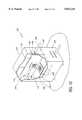
- FIG. 4is a cutaway perspective view of the computer system of FIG. 3.
- FIG. 5is a top crossectional view of a second preferred embodiment of the chambered cooling system of the present invention installed in a desktop computer configuration.
- FIG. 6is a front elevational view of the second preferred embodiment of FIG. 5.
- FIG. 7is a perspective view of a first preferred embodiment of an airflow baffle element of the present invention.
- FIG. 7ais a perspective view of an alternate finger arrangement used in conjunction with the first preferred embodiment of FIG. 7.
- FIG. 8is a crossectional view of the baffle element of FIG. 7, with wiring installed, taken along line 8--8 of FIG. 7.
- FIG. 9is a crossectional view of a second preferred embodiment of the airflow baffle element of the present invention, with electrical wiring installed.
- FIG. 10is a crossectional view of a third preferred embodiment of the airflow baffle element of the present invention, with electrical wiring installed.
- FIG. 11is a perspective view of a fourth preferred embodiment of the airflow baffle element of the present invention, with electrical wiring installed.
- FIG. 12is a cutaway perspective view of a tower computer system, illustrating the baffle element of FIG. 11 installed therein.
- FIG. 3it is seen that the internal components of a computer system 102 are cooled through use of a dual-chambered arrangement within the computer external housing 120.
- the interior volume of the tower/minitower computer system 102is segregated into two essentially discrete "over-under" chambers 104, 106 by a horizontally oriented divider or baffle element 108.
- the baffle element 108may be received and secured in position generally by the horizontal chassis elements 110, 112 within the computer, as described below.
- the baffle element 108may be sized and the chassis elements of the computer system constructed so that when the baffle is installed, airflow between the two chambers 104, 106 is essentially eliminated.
- Two forced airflow generators 114, 116are mounted to the rear wall 118 of the housing 120, each within its respective chamber 104, 106 such that each airflow generator is dedicated to one chamber, and the airflow induced within each of the two chambers is generally co-linear with and flowing in the same direction ("substantially parallel") as that in the other chamber.
- Standard low speed, low noise cooling fans suitable for personal computer applicationsare preferred in this embodiment, although the objectives of the invention may also be met through use of other devices generating forced airflow in place of or in conjunction with the fans 114, 116.
- Each fan 114, 116is oriented on the housing rear wall 118 so as to exhaust air from its respective chamber 104, 106 through one or more perforations 122 in the rear wall 118.
- a separate dedicated cooling exhaust fan 115 integral with the computer power supply 60is also provided in this embodiment.
- the motherboard 152is oriented in a vertical fashion such that the air flowpath 146 coincides with the top surface of the motherboard 152 and CPU 40.
- Air inlets 10 of rectangular crossectionmay be used; however, those of other crossectional shapes may also be employed.
- Ambient airis drawn through the inlets in the direction shown by arrows 128 and 130 into each chamber 104, 106 by the relative low pressure created by that chamber's respective exhaust fan 114, 116.
- the air inletsmay be disposed on said front wall 126 at an elevation roughly equivalent to and in relative transverse alignment with the rotational axis 132 of the blades of fans 114, 116 (e.g., “substantially aligned") so as to minimize changes of direction in the airflow within each chamber.
- One or more of the critical components within the computer housing 120 which require coolinginclude the CPU 40, the disk drive cages 50, 70, and CD-ROM 80 drive. These components may be placed in close physical proximity to the air inlets for each chamber so that unheated inlet air is directly drawn over these components during induction, thereby providing one of the primary benefits of the invention. Furthermore, as will be further described herein, the critical components are disposed at vertical elevations in relation to the airflow stream 146 created by each cooling fan 114, 116 and its respective air inlets 10 to optimize component cooling while striving to minimize turbulence and maintain significant linear airflow within the chamber.
- Inlet baffle elements 144may be installed to restrict the flow of air as required in applications having more preexisting inlets than are required by the invention. That is, inlets 145 which do not have components requiring cooling in direct proximity will be baffled in order to ensure that maximum airflow is drawn through the unbaffled inlets 10 and over the components requiring cooling.
- the placement and orientation of the aforementioned components, coupled with baffling of the internal chambers 104, 106 and baffling of selected front wall air inlets 145increases the efficiency of the cooling system by diverting inlet air away from components which do not require cooling. This diversion reduces the temperature increase of the air encountering the components requiring cooling, and reduces the required mass flow rate of air over these components for a given heat removal rate.
- FIG. 4shows the relative arrangement of the fan 114, air inlets 10, and the various internal components associated with one chamber 104 of the computer system of FIG. 3.
- a generally linear flowpath of air 146is maintained between the air inlets 10 located in the front wall 126 of the housing 120 and the cooling fan 114 located on the rear wall 118.
- the disk drive cage 70is disposed between upper and lower air inlets 10a, 10b such that inlet air flows directly along the upper and lower surfaces of the drive cage 70 after induction without inducing significant turbulence within the chamber 104.
- air inlets positioned in the front wall 126 yet oriented so as to admit airflow on either side of a componentmay be used.
- the baffle element 108is disposed horizontally within the housing 120 so as to form and separate the two tandem chambers 104, 106 of this embodiment.
- a wiring harness 156shown here coupled to the motherboard 152, penetrates the center region of the baffle element 108 to permit electrical coupling of the components in both chambers.
- wiring or optical fibers passing through the baffle elementmay interconnect a variety of components and/or boards within the interior volume of the computer including the motherboard 152, disk drive(s) 50, 70, CD-ROM drive 80, and power supply 60.
- the internal components within a chamber 104, 106may be oriented in a number of different ways while still providing for component cooling and maintaining substantially linear airflow within that chamber.
- the motherboard 152may be oriented vertically and longitudinally in the direction of airflow 146 to accomplish the same result.
- the power supply 60 and associated fan 115are oriented within the chamber 104 in close proximity to the exhaust cooling fan 114 for that chamber in order to maintain the airflow path 146 as linear as possible and minimize any turbulence within the housing 120.
- FIGS. 5 and 6A second embodiment of the present invention is shown in FIGS. 5 and 6. This embodiment optimal for use in a desktop computer.
- the two cooling chambers 104, 106are oriented in tandem (side-by-side) as opposed to the over-under orientation of the tower computer system of the first embodiment described above.
- the linear flowpath 146 between the cooling fans 114, 116 and air inlets 10is maintained in this second embodiment by positioning the components within each chamber horizontally along the front wall 126 of the housing 120 in vertical alignment with the air flowpath 146, while selectively baffling any air inlets which are not required for component cooling.
- the internal baffle element 108is oriented vertically and received in the housing element 110, 112, thereby preventing significant airflow vertically between the chambers 104, 106.
- Wiring 156penetrates the baffle element 108 horizontally through the element's center region.
- a first embodiment of the baffle element 108is constructed with a center element 200 interposed between two substantially planar support elements 202, 204.
- Center element 200may be of generally rectangular shape, and may have a plurality of longitudinal and transverse perforations 210 extending through its thickness such that a plurality of individual fingers 212 are formed.
- the fingers 212may be disposed in a substantially parallel orientation, with two opposing rows 218, 220 being formed such that the distal end 216 of each finger 212 is in close proximity with the distal end 216 of the corresponding finger in the opposing row.
- Center element 200is constructed from any variety of flexible or elastomeric materials such as vinyl, neoprene rubber, or polyethylene such that the fingers 212 are flexible and the distal end 216 of each finger may move in a substantially normal direction 222 to the plane of the element 200, and in relation to one another.
- the center element 200may be constructed of a substantially rigid material, and the fingers 212 pivotally attached and preloaded thereto using a flexible spring element 213 or similar arrangement, as shown in FIG. 7a.
- the dimensions of perforations 210are controlled, and the diameter of each finger 224 is maintained sufficiently small such that airflow around an object of fairly small diameter (such as an electrical wire 152 or fiber-optic cable) inserted through the fingers is minimized. It can be appreciated that a variety of finger shapes and orientations may be used with equal effectiveness.
- the support elements 202, 204each have a passage 206, 208 extending through a central portion thereof, such that the passages 206, 208 of both support elements 202, 204 substantially communicate when those elements are mated flush with one another.
- the shape of the passage 206, 208 through each support elementmay be configured to not restrict movement of the fingers 212 while defining a perimeter that is smaller than the perimeter of the center element 200.
- the passages 206, 208may be sized to permit movement of the fingers 212, while the support elements 202, 204 act to retain the center element 200 in the desired position when assembled, as discussed below.
- the support elements 202, 204may be constructed of substantially any material with sufficient rigidity to adequately retain the center element 200 in relative alignment, including plastics, rubber, composites, or metal.
- the support elements 202, 204may be constructed from an ESD (electrostatic discharge) safe material.
- the center element 200When the baffle element 108 is assembled, the center element 200 may be maintained in position between the support elements 202, 204 by way of the overlap region 228 between the inner periphery 230 of each support element and the outer periphery 232 of the center element 200.
- the center elementmay therefore be "sandwiched" between the two support elements, all three components being held in relative position to one another through the use of rivets 209, threaded fasteners, adhesives, or similar conventional fastening means.
- a large variety of methods for maintaining the relative alignment between the center element 200 and the support elementsmay be employed with equal success and without departing from the spirit of the invention.
- a groove 240is formed between the support elements 202, 204 which extends around the periphery of the baffle element 108.
- the assembled baffle element 108may be positioned and secured within the computer housing of FIG. 3 by way of horizontal chassis elements 110, 112.
- the groove 240 formed between the support elements 202, 204receives the horizontal elements, both being sized accordingly to create a frictional fit between the chassis elements 110, 112 and the interior surfaces of the support elements 202, 204 forming the groove 240 such that the baffle element may slide in a horizontal direction 244 during system maintenance to permit easy installation and removal.
- the baffle elementslides vertically during installation and removal.
- baffle elementmay be permanently affixed to the computer chassis (such as by adhesives or welding) if so desired.
- the baffle element 108is sized and the chassis elements 110, 112 constructed such that when the baffle element is received by the chassis elements, airflow between the chambers 104, 106 is substantially eliminated. Airtight sealing of the sliding grooves 240, 242 or other mounting apparatus is not required in that some leakage around the baffle element 108 is allowable; however, gross leakage through or around the baffle will mitigate the benefits provided by the invention.
- an electrical wire or ribbon cable 156is passed through the thickness of the baffle element 108 by way of the perforations 210 in the center element 200.
- the flexible fingers 212deflect thereby permitting passage of the cable 156 through the baffle element 108, while the resiliency of the fingers 212 maintain their distal ends 216 in contact with the cable 156 so as to mitigate the flow of air around the cable and therefore between the individual chambers 104, 106 within the computer housing 120. It can be appreciated that cables of varying sizes and configurations may pass through the perforations 210 of the center element 200 in this manner.
- FIG. 9shows a second embodiment of the baffle element of the present invention.
- the baffle elementmay be constructed using a single support element 202 for reduced weight and space.
- This single support element 202is mated to the flexible center element 200 such that the passage 206 substantially aligns with the fingers 212 within the center element 200, thereby providing the fingers 212 with sufficient transverse mobility.
- the center portion 200is mounted to the support element 202 using any of the aforementioned conventional fastening techniques, thereby maintaining both elements 200, 202 in relative alignment during use.
- the support elementsupports the weight of the center element 200 and electrical wires 152 penetrating between the fingers 212 during use.
- the baffle elementmay then be slidably, pivotally, or permanently mounted, as desired, to the computer chassis using any number of techniques well understood in the art.
- FIG. 10shows a third embodiment of the present invention, wherein the baffle support element 202 and fingers 212 are unified and fabricated from one or more sheets of resilient material. Transverse and longitudinal perforations 210 made in the material create the fingers 212, which may be flexed into and out of the plane of the support element to permit cabling or other objects to pass through.
- the material used for the support element 202 and fingers 212 of this embodimentprovides mechanical stability and strength when the baffle element 108 is installed in the computer chassis, and also permits dislocation of the fingers without breaking, and sealing of the installed cable 156. Polyethylene or other similar plastics may be used to form the support element 202, although other types of material will suffice.
- the material used in this embodiment for the support element 202 and fingers 212may be ESD safe. This embodiment carries the primary benefit of great simplicity of manufacture.
- FIG. 11shows a fourth embodiment of the baffle element 108 of the present invention.
- a three-chamber baffle elementis constructed through the use of two discrete support elements 202, 204 mated to one another at right or oblique angles.
- One or more center elements 200are mated to the support elements in alignment with their passages 206 to permit the sealed passage of electrical wires or other objects between each of the three chambers created when the baffle element 108 is installed within a computer housing 120.
- baffle element 11could be installed in a tower-type housing 120 as previously described such that the direction of airflow 146 in all three chambers, 104, 106, 107 is oriented front-to-back, as shown in FIG. 12.
- a large number of different baffle element geometries and arrangementsare contemplated, depending on the configuration of the computer system chassis into which the baffle is being fit, the number of desired chambers, and the number of available cooling fans.
- the chambered forced cooling system of the present inventionprovides enhanced cooling of critical computer or electronic system components, thereby increasing component longevity and improving overall system reliability. Most notably, this enhanced cooling is provided with no increase in fan capacity or required reduction in inlet air temperature. Additionally, the baffle element used with the system allows for the routing of electrical cabling throughout the interior of the enclosure such that the desired airflow within each of the chambers (and increased efficiency resulting therefrom) are preserved. Maintenance of the system is also facilitated through the easy installation and removal of the baffle element(s) and any cabling routed therein.
Landscapes
- Engineering & Computer Science (AREA)
- Theoretical Computer Science (AREA)
- Human Computer Interaction (AREA)
- Physics & Mathematics (AREA)
- General Engineering & Computer Science (AREA)
- General Physics & Mathematics (AREA)
- Cooling Or The Like Of Electrical Apparatus (AREA)
Abstract
Description
Claims (24)
Priority Applications (2)
| Application Number | Priority Date | Filing Date | Title |
|---|---|---|---|
| US08/835,138US5813243A (en) | 1997-04-04 | 1997-04-04 | Chambered forced cooling system |
| US08/880,175US5860291A (en) | 1997-04-04 | 1997-06-20 | Chambered forced cooling method |
Applications Claiming Priority (1)
| Application Number | Priority Date | Filing Date | Title |
|---|---|---|---|
| US08/835,138US5813243A (en) | 1997-04-04 | 1997-04-04 | Chambered forced cooling system |
Related Child Applications (1)
| Application Number | Title | Priority Date | Filing Date |
|---|---|---|---|
| US08/880,175DivisionUS5860291A (en) | 1997-04-04 | 1997-06-20 | Chambered forced cooling method |
Publications (1)
| Publication Number | Publication Date |
|---|---|
| US5813243Atrue US5813243A (en) | 1998-09-29 |
Family
ID=25268688
Family Applications (2)
| Application Number | Title | Priority Date | Filing Date |
|---|---|---|---|
| US08/835,138Expired - LifetimeUS5813243A (en) | 1997-04-04 | 1997-04-04 | Chambered forced cooling system |
| US08/880,175Expired - LifetimeUS5860291A (en) | 1997-04-04 | 1997-06-20 | Chambered forced cooling method |
Family Applications After (1)
| Application Number | Title | Priority Date | Filing Date |
|---|---|---|---|
| US08/880,175Expired - LifetimeUS5860291A (en) | 1997-04-04 | 1997-06-20 | Chambered forced cooling method |
Country Status (1)
| Country | Link |
|---|---|
| US (2) | US5813243A (en) |
Cited By (90)
| Publication number | Priority date | Publication date | Assignee | Title |
|---|---|---|---|---|
| US5978218A (en)* | 1994-11-24 | 1999-11-02 | Advantest Corp. | Cooling system for IC tester |
| US6021042A (en)* | 1997-08-06 | 2000-02-01 | Intel Corporation | Cooling duct for a computer cooling system with redundant air moving units |
| US6058011A (en)* | 1999-02-12 | 2000-05-02 | Compaq Computer Corporation | Computer chassis with integrated cooling features |
| WO2000054066A1 (en)* | 1999-03-12 | 2000-09-14 | Credence Systems Corporation | Cooling system for test head |
| US6141213A (en)* | 1997-06-24 | 2000-10-31 | Sun Microsystems, Inc. | Computer with high airflow and low acoustic noise |
| US6163453A (en)* | 1998-12-28 | 2000-12-19 | Foxconn Precision Components Co., Ltd. | Heat dissipation enhancing device |
| US6288897B1 (en)* | 1999-03-18 | 2001-09-11 | Simone Fritschle | Casing with a fan unit and fan unit |
| US6324056B1 (en)* | 1998-04-08 | 2001-11-27 | Siemens Aktiengesellschaft | Device for cooling a personal computer housed in a casing |
| US6330156B1 (en) | 1999-08-10 | 2001-12-11 | Micron Technology, Inc. | Card support and cooler bracket |
| WO2002016854A1 (en)* | 2000-08-23 | 2002-02-28 | Toc Technology, Llc | Computer room air flow method and apparatus |
| US6400567B1 (en)* | 2000-10-19 | 2002-06-04 | Fujitsu Network Communications, Inc. | Equipment enclosure having separate compartments cooled by separate cooling airflows |
| US6422730B1 (en)* | 2000-03-17 | 2002-07-23 | Super Vision International, Inc. | Fiber optic light source with two chamber cooling |
| US6430041B1 (en) | 1999-10-20 | 2002-08-06 | Micronpc, Llc | Computer cooling system and method |
| US6487074B1 (en)* | 1999-03-19 | 2002-11-26 | The Furukawa Electric Co., Ltd. | Cooling system for electronic device |
| US6496366B1 (en) | 1999-10-26 | 2002-12-17 | Rackable Systems, Llc | High density computer equipment storage system |
| US20030030978A1 (en)* | 2001-08-10 | 2003-02-13 | Garnett Paul J. | Cooling computer systems |
| USD473225S1 (en) | 2001-02-20 | 2003-04-15 | Rackable Systems, Inc. | Portion of a bank of computer chassis mounted to rack bars |
| US6574970B2 (en) | 2000-02-18 | 2003-06-10 | Toc Technology, Llc | Computer room air flow method and apparatus |
| US6595018B2 (en)* | 2001-06-29 | 2003-07-22 | International Business Machines Corporation | Logic module refrigeration system with condensation control |
| US6597569B1 (en)* | 2000-06-29 | 2003-07-22 | Intel Corporation | Partitioned computer platform |
| US20030214782A1 (en)* | 2002-05-16 | 2003-11-20 | Osborn Jay K. | Computing apparatus with cooling fan |
| US6654242B2 (en)* | 2000-12-05 | 2003-11-25 | Nec Corporation | Electronic apparatus with built-in CPU |
| US6657320B1 (en)* | 1999-11-03 | 2003-12-02 | Active Power, Inc. | Integrated flywheel uninterruptible power supply system |
| US20030223194A1 (en)* | 2002-05-31 | 2003-12-04 | Michael Schmid | Tower PC with maximum utilization of internal volume |
| US20030223195A1 (en)* | 2002-05-31 | 2003-12-04 | Michael Schmid | Tower PC configuration |
| US6661666B1 (en) | 2002-09-24 | 2003-12-09 | Agilent Technologies, Inc. | Device for enhancing the local cooling of electronic packages subject to laminar air flow |
| US6667891B2 (en) | 2000-02-18 | 2003-12-23 | Rackable Systems, Inc. | Computer chassis for dual offset opposing main boards |
| US20040057210A1 (en)* | 2002-09-20 | 2004-03-25 | Wilson Jeremy I. | Composite construction baffle for modular electronic systems |
| US6728099B1 (en)* | 1998-11-13 | 2004-04-27 | Hewlett-Packard Development Company, L.P. | Electrical component having a hybrid air cooling system and method |
| US6742583B2 (en)* | 1999-08-20 | 2004-06-01 | Nokia Corporation | Cooling system for a cabinet |
| US20040228087A1 (en)* | 2003-05-16 | 2004-11-18 | Giovanni Coglitore | Computer rack with power distribution system |
| US6850408B1 (en) | 1999-10-26 | 2005-02-01 | Rackable Systems, Inc. | High density computer equipment storage systems |
| US20050153649A1 (en)* | 2004-01-13 | 2005-07-14 | Bettridge James M. | Cabinet for computer devices with air distribution device |
| US20050168945A1 (en)* | 2003-12-29 | 2005-08-04 | Giovanni Coglitore | Computer rack cooling system with variable airflow impedance |
| US20050213292A1 (en)* | 2004-03-24 | 2005-09-29 | Yin-Hung Chen | Internal arrangement of computer case |
| US20050219812A1 (en)* | 2004-04-01 | 2005-10-06 | Strobel Larry A | Environmental control system for personal computers |
| US20050219811A1 (en)* | 2004-03-31 | 2005-10-06 | Giovanni Coglitore | Computer rack cooling system |
| US6972953B1 (en)* | 1999-10-04 | 2005-12-06 | Apple Computer, Inc. | Thermal management system |
| US20060044753A1 (en)* | 2004-08-26 | 2006-03-02 | Henry Wong | Integrated power supply and air inlet unit |
| US20060249295A1 (en)* | 2005-05-05 | 2006-11-09 | Lin-Wei Chang | Wind fender for mainboards |
| FR2890825A1 (en)* | 2005-09-15 | 2007-03-16 | Thomson Licensing Sas | Cooling system for high definition decoder, has ventilator positioned in adapter using silent block to inject air directly to hard disk of decoder, where certain space is provided between ventilator and wall of adapter |
| US20070081307A1 (en)* | 2005-10-07 | 2007-04-12 | Fujitsu Limited | Electronic apparatus |
| US20070291450A1 (en)* | 2006-06-19 | 2007-12-20 | Hayato Watanabe | Information processing apparatus |
| US20080113603A1 (en)* | 2006-10-19 | 2008-05-15 | Atallah Jean G | Computer system cooling system |
| USD571641S1 (en)* | 2007-10-15 | 2008-06-24 | Upsite Technologies, Inc. | Grommet |
| USRE40512E1 (en)* | 1999-06-23 | 2008-09-23 | Samsung Electronics Co., Ltd. | Acoustic convection apparatus |
| US7434412B1 (en)* | 2005-10-27 | 2008-10-14 | Sun Microsystems, Inc. | Computer equipment temperature control system and methods for operating the same |
| US20090016010A1 (en)* | 2007-06-13 | 2009-01-15 | Vinson Wade D | Component layout in an enclosure |
| US7507912B1 (en) | 2007-10-01 | 2009-03-24 | Upsite Technologies, Inc. | Grommet for cables |
| US20090141441A1 (en)* | 2007-12-03 | 2009-06-04 | Sun Microsystems, Inc. | Air baffle with integrated tool-less expansion card attachment |
| USD597823S1 (en) | 2007-10-15 | 2009-08-11 | Upsite Technologies, Inc. | Grommet |
| WO2009142644A1 (en)* | 2008-05-23 | 2009-11-26 | Hewlett-Packard Development Company, L.P. | Computer chassis |
| WO2010005431A1 (en)* | 2008-07-09 | 2010-01-14 | Hewlett-Packard Development Company, L.P. | Dedicated air inlets and outlets for computer chassis chambers |
| US20100014250A1 (en)* | 2008-07-17 | 2010-01-21 | Olympus Medical Systems Corp. | Interior cooling structure and ultrasound imaging apparatus |
| US20100059270A1 (en)* | 2008-09-11 | 2010-03-11 | Joseph Yeh | Hybrid cooling system for outdoor electronics enclosure |
| US7755889B2 (en) | 2007-06-12 | 2010-07-13 | Hewlett-Packard Development Company, L.P. | Air Manifold for electronic module enclosure |
| USRE41863E1 (en) | 2001-09-13 | 2010-10-26 | Upsite Technologies, Inc. | Toolless, self closing floor grommet closure for cable openings and the like in raised floors of data centers office buildings and other air conditioned structures |
| US20110090636A1 (en)* | 2009-10-15 | 2011-04-21 | Hong Fu Jin Precision Industry (Shenzhen) Co., Ltd. | Heat dissipating system |
| US20110138406A1 (en)* | 2009-01-07 | 2011-06-09 | Motonari Ogura | Electronic device |
| US20110228475A1 (en)* | 2010-03-17 | 2011-09-22 | International Business Machines Corporation | Enclosure with concurrently maintainable field replaceable units |
| US20110235261A1 (en)* | 2010-03-23 | 2011-09-29 | Lenovo (Singapore) Pte, Ltd. | Apparatus, system, and method of power supply disposition and cooling |
| US20120090821A1 (en)* | 2009-06-15 | 2012-04-19 | Tian Weiqiang | Insert box with front and rear insertion and heat dissipation method thereof |
| DE102011005838A1 (en)* | 2011-03-21 | 2012-09-27 | Siemens Aktiengesellschaft | Device for actively venting internals of a drawer of a control cabinet |
| US20120290748A1 (en)* | 2010-02-01 | 2012-11-15 | Thomson Licensing | Apparatus and method for transforming a consumer device enclosure |
| WO2012173610A1 (en)* | 2011-06-15 | 2012-12-20 | Hewlett-Packard Development Company, L.P. | Thermal chamber partition and fan unit for computer system |
| US20140216681A1 (en)* | 2013-02-04 | 2014-08-07 | Abb Oy | Cooling assembly |
| US20140312025A1 (en)* | 2013-04-23 | 2014-10-23 | Alto-Shaam, Inc. | Zero Clearance Combination Oven |
| US20150305194A1 (en)* | 2012-12-31 | 2015-10-22 | Huawei Technologies Co., Ltd. | Heat dissipation system and communications device |
| DE102014223537A1 (en)* | 2014-11-18 | 2016-05-19 | Friedrich Lütze GmbH | Device for installing electrical components |
| US9426932B2 (en) | 2013-03-13 | 2016-08-23 | Silicon Graphics International Corp. | Server with heat pipe cooling |
| US9596784B2 (en)* | 2015-03-13 | 2017-03-14 | True Power Electric, LLC | Multi-chamber cooling system |
| US9612920B2 (en) | 2013-03-15 | 2017-04-04 | Silicon Graphics International Corp. | Hierarchical system manager rollback |
| WO2017123486A1 (en)* | 2016-01-11 | 2017-07-20 | 3M Innovative Properties Company | Computer with baffles directing and separating air flow for high cooling |
| US20180120906A1 (en)* | 2015-05-04 | 2018-05-03 | Molex, Llc | Computing device using bypass assembly |
| US20180364071A1 (en)* | 2017-06-16 | 2018-12-20 | Daniel Rivera | Photonic computer system comprised of stack disk arrays running on but not limited to quantum software |
| US10178798B1 (en)* | 2016-11-23 | 2019-01-08 | Pure Storage, Inc. | Electronics enclosure with airflow management |
| US10305204B2 (en) | 2013-02-27 | 2019-05-28 | Molex, Llc | High speed bypass cable for use with backplanes |
| US10367280B2 (en) | 2015-01-11 | 2019-07-30 | Molex, Llc | Wire to board connectors suitable for use in bypass routing assemblies |
| WO2020168167A1 (en)* | 2019-02-15 | 2020-08-20 | Pensando Systems Inc. | Methods and systems for thermal control |
| US10761577B1 (en)* | 2019-08-29 | 2020-09-01 | Google Llc | Liquid soluble gas sealed cooling system |
| US11108176B2 (en) | 2016-01-11 | 2021-08-31 | Molex, Llc | Routing assembly and system using same |
| US11114807B2 (en) | 2015-01-11 | 2021-09-07 | Molex, Llc | Circuit board bypass assemblies and components therefor |
| US11151300B2 (en) | 2016-01-19 | 2021-10-19 | Molex, Llc | Integrated routing assembly and system using same |
| US11259440B1 (en)* | 2020-11-09 | 2022-02-22 | Antec Inc. | Computer case |
| US20220078938A1 (en)* | 2020-09-10 | 2022-03-10 | Dell Products, L.P. | Profile-modeling cable clip for sealing airflow in an information handling system (ihs) chassis |
| US11324138B2 (en)* | 2020-06-29 | 2022-05-03 | Dell Products L.P. | Systems and methods for minimizing airflow bypass and recirculation through a cable channel |
| US11326621B2 (en) | 2018-09-07 | 2022-05-10 | International Business Machines Corporation | Implementing electronic enclosure cooling containment for concurrent maintenance actions |
| US20230284411A1 (en)* | 2022-03-03 | 2023-09-07 | Arista Networks, Inc. | Multiple chassis cooling zones |
| US11911790B2 (en) | 2022-02-25 | 2024-02-27 | Saudi Arabian Oil Company | Applying corrosion inhibitor within tubulars |
| US20250013273A1 (en)* | 2023-07-06 | 2025-01-09 | Dongguan Sunpro Industrial Development Co.,Ltd | Split-type case structure that facilitates heat dissipation |
Families Citing this family (34)
| Publication number | Priority date | Publication date | Assignee | Title |
|---|---|---|---|---|
| US6123266A (en)* | 1997-07-11 | 2000-09-26 | Lucent Technologies Inc. | Cooling system for stand-alone battery cabinets |
| US6564571B2 (en)* | 2000-07-17 | 2003-05-20 | Liebert Corporation | High availability energy |
| US6556438B1 (en)* | 2000-10-18 | 2003-04-29 | Compaq Information Technologies Group Llp | Dense packaging and cooling system for use with a server or other processor-based device |
| TW551545U (en)* | 2002-08-07 | 2003-09-01 | Tzung-Yan Tsai | Structure of power supply |
| US20040252455A1 (en)* | 2003-03-20 | 2004-12-16 | Kuo Yi-Lung | Computer cooling system with fan |
| US7158379B2 (en)* | 2003-12-12 | 2007-01-02 | Cisco Technology, Inc. | Device for removing heat from a power connector |
| US20050270298A1 (en)* | 2004-05-14 | 2005-12-08 | Mercury Computer Systems, Inc. | Daughter card approach to employing multiple graphics cards within a system |
| US7248472B2 (en)* | 2004-05-21 | 2007-07-24 | Hewlett-Packard Development Company, L.P. | Air distribution system |
| US7333330B2 (en)* | 2005-02-04 | 2008-02-19 | Technology Advanced Group, Inc. | Electronic component chassis with isolated power supply cooling |
| JP4818700B2 (en)* | 2005-12-02 | 2011-11-16 | 株式会社日立製作所 | Storage controller |
| US7885062B2 (en)* | 2005-12-09 | 2011-02-08 | Nvidia Corporation | Computer chassis with partitions for improved airflow |
| US7495906B2 (en)* | 2006-04-21 | 2009-02-24 | International Business Machines Corporation | Multiple hard disk drive assembly cooling |
| US7595985B2 (en)* | 2006-06-19 | 2009-09-29 | Panduit Corp. | Network cabinet with thermal air flow management |
| JP2008090569A (en) | 2006-10-02 | 2008-04-17 | Sony Corp | Electronic apparatus and cooling method for it |
| US20080186668A1 (en)* | 2007-02-07 | 2008-08-07 | Motorola, Inc. | Acoustic noise suppression device |
| US7714731B2 (en)* | 2007-06-22 | 2010-05-11 | Andrew Llc | Detection of air filter clogging and provision of emergency ventilation in an outdoor electronics cabinet cooled by ambient forced air |
| US7978469B2 (en)* | 2007-08-27 | 2011-07-12 | Panagiotis Tsakanikas | Computer apparatus and method having dual air chambers |
| US20090061755A1 (en)* | 2007-08-28 | 2009-03-05 | Panduit Corp. | Intake Duct |
| JP5086047B2 (en)* | 2007-12-07 | 2012-11-28 | 株式会社日立製作所 | Receiver |
| US8009417B2 (en)* | 2009-08-28 | 2011-08-30 | Hewlett-Packard Development Company, L.P. | Removable airflow guide assembly for a computer system |
| CN201548898U (en)* | 2009-09-29 | 2010-08-11 | 鸿富锦精密工业(深圳)有限公司 | Computer case cooling system |
| CN201654608U (en)* | 2009-11-26 | 2010-11-24 | 鸿富锦精密工业(深圳)有限公司 | Computer system |
| CN201654639U (en)* | 2009-11-26 | 2010-11-24 | 鸿富锦精密工业(深圳)有限公司 | Computer system |
| CN201654637U (en)* | 2009-11-26 | 2010-11-24 | 鸿富锦精密工业(深圳)有限公司 | Computer system |
| CN103064481A (en)* | 2011-10-21 | 2013-04-24 | 鸿富锦精密工业(深圳)有限公司 | Server |
| US8634193B2 (en)* | 2011-12-05 | 2014-01-21 | Rockwell Automation Technologies, Inc. | Device and method using induction to improve natural convection cooling |
| US9839155B2 (en) | 2012-05-16 | 2017-12-05 | Panduit Corp. | Thermal ducting system |
| US20140063726A1 (en)* | 2012-09-06 | 2014-03-06 | You-Chi Liu | Computer cooling system |
| CN104679163A (en)* | 2013-11-30 | 2015-06-03 | 鸿富锦精密工业(深圳)有限公司 | Electronic device case |
| CN104586432B (en)* | 2015-01-27 | 2017-12-15 | 深圳市理邦精密仪器股份有限公司 | Car-type ultrasonic diagnostic equipment and its cabinet |
| CN105988527A (en)* | 2015-01-31 | 2016-10-05 | 鸿富锦精密工业(武汉)有限公司 | Electronic device shell |
| JP6891600B2 (en)* | 2017-03-31 | 2021-06-18 | 富士通株式会社 | Information processing device |
| US10231034B1 (en)* | 2018-01-03 | 2019-03-12 | Dell Products L.P. | Information handling system cable seal |
| TWM620190U (en)* | 2021-08-13 | 2021-11-21 | 華碩電腦股份有限公司 | Computer apparatus and host module thereof |
Citations (20)
| Publication number | Priority date | Publication date | Assignee | Title |
|---|---|---|---|---|
| US3523156A (en)* | 1968-09-18 | 1970-08-04 | Lawrence Phillips Jr | Electrical service center having an improved moisture barrier |
| US3873757A (en)* | 1974-04-08 | 1975-03-25 | Bell Telephone Labor Inc | Communications circuit protector |
| US4267995A (en)* | 1979-10-09 | 1981-05-19 | Mcmillan Ronald R | Wire holder |
| US4289924A (en)* | 1980-09-24 | 1981-09-15 | General Motors Corporation | Injectable grommet assembly |
| US4296454A (en)* | 1979-10-22 | 1981-10-20 | Bell Telephone Laboratories, Incorporated | Molded circuit retaining enclosure with a receptacle means for securing individual circuit components |
| US4527285A (en)* | 1982-03-29 | 1985-07-02 | International Business Machines Corporation | Pluggable terminal architecture |
| US5066832A (en)* | 1989-10-26 | 1991-11-19 | Eaton Corporation | Plastic enclosure box for electrical apparatus |
| US5101079A (en)* | 1990-07-11 | 1992-03-31 | Thomas & Betts Corporation | Enclosure for an electrical terminal block including barrier means for a cable entry opening |
| US5136465A (en)* | 1990-10-29 | 1992-08-04 | International Business Machines Corp. | Personal computer with tandem air flow dual fans and baffle directed air cooling |
| US5168424A (en)* | 1990-02-15 | 1992-12-01 | International Business Machines Corporation | Multi unit electrical apparatus with dual inlet fan positioned opposite unit bays |
| US5218514A (en)* | 1992-07-10 | 1993-06-08 | International Business Machines Corporation | Compact high power personal computer with improved air cooling system |
| US5254808A (en)* | 1990-07-11 | 1993-10-19 | Thomas & Betts Corporation | Enclosure for an electrical terminal block including barrier means for a cable entry opening |
| US5378174A (en)* | 1993-03-18 | 1995-01-03 | The Whitaker Corporation | Enclosure for variety of terminal blocks |
| US5414591A (en)* | 1991-04-15 | 1995-05-09 | Hitachi, Ltd. | Magnetic disk storage system |
| US5432674A (en)* | 1994-03-02 | 1995-07-11 | Compaq Computer Corporation | Computer tower unit having internal air flow control baffle structure |
| US5440450A (en)* | 1990-09-14 | 1995-08-08 | Next, Inc. | Housing cooling system |
| US5460441A (en)* | 1994-11-01 | 1995-10-24 | Compaq Computer Corporation | Rack-mounted computer apparatus |
| US5473507A (en)* | 1991-12-11 | 1995-12-05 | Hewlett-Packard Company | Chassis of a device |
| US5493457A (en)* | 1991-10-18 | 1996-02-20 | Matsushita Electric Industrial Co., Ltd. | Optical disk apparatus with cooling arrangement |
| US5576931A (en)* | 1994-05-03 | 1996-11-19 | The Panda Project | Computer with two fans and two air circulation areas |
Family Cites Families (7)
| Publication number | Priority date | Publication date | Assignee | Title |
|---|---|---|---|---|
| US4860163A (en)* | 1988-08-05 | 1989-08-22 | American Telephone And Telegraph Company | Communication equipment cabinet cooling arrangement |
| US5173819A (en)* | 1988-10-05 | 1992-12-22 | Hitachi, Ltd. | Disk apparatus having an improved cooling structure |
| DE3837744A1 (en)* | 1988-11-07 | 1990-05-10 | Knuerr Mechanik Ag | ASSEMBLY CARRIERS FOR PCBS WITH ELECTRONIC COMPONENTS |
| US5287244A (en)* | 1992-05-19 | 1994-02-15 | Sun Microsystems, Inc. | Computer housing with low noise cooling system |
| US5477417A (en)* | 1992-08-28 | 1995-12-19 | Kabushiki Kaisha Toshiba | Electronic equipment having integrated circuit device and temperature sensor |
| JP3213156B2 (en)* | 1994-03-15 | 2001-10-02 | 富士通株式会社 | Electronics |
| CA2165749C (en)* | 1995-12-20 | 2003-04-08 | Paul D. Cochrane | Electronic equipment having air flow cooling passages |
- 1997
- 1997-04-04USUS08/835,138patent/US5813243A/ennot_activeExpired - Lifetime
- 1997-06-20USUS08/880,175patent/US5860291A/ennot_activeExpired - Lifetime
Patent Citations (20)
| Publication number | Priority date | Publication date | Assignee | Title |
|---|---|---|---|---|
| US3523156A (en)* | 1968-09-18 | 1970-08-04 | Lawrence Phillips Jr | Electrical service center having an improved moisture barrier |
| US3873757A (en)* | 1974-04-08 | 1975-03-25 | Bell Telephone Labor Inc | Communications circuit protector |
| US4267995A (en)* | 1979-10-09 | 1981-05-19 | Mcmillan Ronald R | Wire holder |
| US4296454A (en)* | 1979-10-22 | 1981-10-20 | Bell Telephone Laboratories, Incorporated | Molded circuit retaining enclosure with a receptacle means for securing individual circuit components |
| US4289924A (en)* | 1980-09-24 | 1981-09-15 | General Motors Corporation | Injectable grommet assembly |
| US4527285A (en)* | 1982-03-29 | 1985-07-02 | International Business Machines Corporation | Pluggable terminal architecture |
| US5066832A (en)* | 1989-10-26 | 1991-11-19 | Eaton Corporation | Plastic enclosure box for electrical apparatus |
| US5168424A (en)* | 1990-02-15 | 1992-12-01 | International Business Machines Corporation | Multi unit electrical apparatus with dual inlet fan positioned opposite unit bays |
| US5254808A (en)* | 1990-07-11 | 1993-10-19 | Thomas & Betts Corporation | Enclosure for an electrical terminal block including barrier means for a cable entry opening |
| US5101079A (en)* | 1990-07-11 | 1992-03-31 | Thomas & Betts Corporation | Enclosure for an electrical terminal block including barrier means for a cable entry opening |
| US5440450A (en)* | 1990-09-14 | 1995-08-08 | Next, Inc. | Housing cooling system |
| US5136465A (en)* | 1990-10-29 | 1992-08-04 | International Business Machines Corp. | Personal computer with tandem air flow dual fans and baffle directed air cooling |
| US5414591A (en)* | 1991-04-15 | 1995-05-09 | Hitachi, Ltd. | Magnetic disk storage system |
| US5493457A (en)* | 1991-10-18 | 1996-02-20 | Matsushita Electric Industrial Co., Ltd. | Optical disk apparatus with cooling arrangement |
| US5473507A (en)* | 1991-12-11 | 1995-12-05 | Hewlett-Packard Company | Chassis of a device |
| US5218514A (en)* | 1992-07-10 | 1993-06-08 | International Business Machines Corporation | Compact high power personal computer with improved air cooling system |
| US5378174A (en)* | 1993-03-18 | 1995-01-03 | The Whitaker Corporation | Enclosure for variety of terminal blocks |
| US5432674A (en)* | 1994-03-02 | 1995-07-11 | Compaq Computer Corporation | Computer tower unit having internal air flow control baffle structure |
| US5576931A (en)* | 1994-05-03 | 1996-11-19 | The Panda Project | Computer with two fans and two air circulation areas |
| US5460441A (en)* | 1994-11-01 | 1995-10-24 | Compaq Computer Corporation | Rack-mounted computer apparatus |
Cited By (153)
| Publication number | Priority date | Publication date | Assignee | Title |
|---|---|---|---|---|
| US5978218A (en)* | 1994-11-24 | 1999-11-02 | Advantest Corp. | Cooling system for IC tester |
| US6141213A (en)* | 1997-06-24 | 2000-10-31 | Sun Microsystems, Inc. | Computer with high airflow and low acoustic noise |
| US6021042A (en)* | 1997-08-06 | 2000-02-01 | Intel Corporation | Cooling duct for a computer cooling system with redundant air moving units |
| US6324056B1 (en)* | 1998-04-08 | 2001-11-27 | Siemens Aktiengesellschaft | Device for cooling a personal computer housed in a casing |
| US6728099B1 (en)* | 1998-11-13 | 2004-04-27 | Hewlett-Packard Development Company, L.P. | Electrical component having a hybrid air cooling system and method |
| US6163453A (en)* | 1998-12-28 | 2000-12-19 | Foxconn Precision Components Co., Ltd. | Heat dissipation enhancing device |
| US6058011A (en)* | 1999-02-12 | 2000-05-02 | Compaq Computer Corporation | Computer chassis with integrated cooling features |
| WO2000054066A1 (en)* | 1999-03-12 | 2000-09-14 | Credence Systems Corporation | Cooling system for test head |
| US6288897B1 (en)* | 1999-03-18 | 2001-09-11 | Simone Fritschle | Casing with a fan unit and fan unit |
| US6487074B1 (en)* | 1999-03-19 | 2002-11-26 | The Furukawa Electric Co., Ltd. | Cooling system for electronic device |
| USRE40512E1 (en)* | 1999-06-23 | 2008-09-23 | Samsung Electronics Co., Ltd. | Acoustic convection apparatus |
| US6330156B1 (en) | 1999-08-10 | 2001-12-11 | Micron Technology, Inc. | Card support and cooler bracket |
| US6742583B2 (en)* | 1999-08-20 | 2004-06-01 | Nokia Corporation | Cooling system for a cabinet |
| US6972953B1 (en)* | 1999-10-04 | 2005-12-06 | Apple Computer, Inc. | Thermal management system |
| US6430041B1 (en) | 1999-10-20 | 2002-08-06 | Micronpc, Llc | Computer cooling system and method |
| US6822859B2 (en) | 1999-10-26 | 2004-11-23 | Rackable Systems, Inc. | Computer rack cooling system |
| US20030035268A1 (en)* | 1999-10-26 | 2003-02-20 | Giovanni Coglitore | High density computer equipment storage system |
| US8582290B2 (en) | 1999-10-26 | 2013-11-12 | Silicon Graphics International Corp. | High density computer equipment storage system |
| US6496366B1 (en) | 1999-10-26 | 2002-12-17 | Rackable Systems, Llc | High density computer equipment storage system |
| US6850408B1 (en) | 1999-10-26 | 2005-02-01 | Rackable Systems, Inc. | High density computer equipment storage systems |
| US20040004813A1 (en)* | 1999-10-26 | 2004-01-08 | Giovanni Coglitore | Computer rack cooling system |
| US6741467B2 (en) | 1999-10-26 | 2004-05-25 | Rackable Systems, Inc. | High density computer equipment storage system |
| US20070159790A1 (en)* | 1999-10-26 | 2007-07-12 | Giovanni Coglitore | High density computer equipment storage system |
| JP2009201351A (en)* | 1999-11-03 | 2009-09-03 | Active Power Inc | Integrated flywheel uninterruptible power supply system |
| US6657320B1 (en)* | 1999-11-03 | 2003-12-02 | Active Power, Inc. | Integrated flywheel uninterruptible power supply system |
| US6745579B2 (en) | 2000-02-18 | 2004-06-08 | Toc Technology, Llc | Computer room air flow method and apparatus |
| US6667891B2 (en) | 2000-02-18 | 2003-12-23 | Rackable Systems, Inc. | Computer chassis for dual offset opposing main boards |
| US6574970B2 (en) | 2000-02-18 | 2003-06-10 | Toc Technology, Llc | Computer room air flow method and apparatus |
| US6422730B1 (en)* | 2000-03-17 | 2002-07-23 | Super Vision International, Inc. | Fiber optic light source with two chamber cooling |
| US6597569B1 (en)* | 2000-06-29 | 2003-07-22 | Intel Corporation | Partitioned computer platform |
| WO2002016854A1 (en)* | 2000-08-23 | 2002-02-28 | Toc Technology, Llc | Computer room air flow method and apparatus |
| US6400567B1 (en)* | 2000-10-19 | 2002-06-04 | Fujitsu Network Communications, Inc. | Equipment enclosure having separate compartments cooled by separate cooling airflows |
| US6654242B2 (en)* | 2000-12-05 | 2003-11-25 | Nec Corporation | Electronic apparatus with built-in CPU |
| USD473225S1 (en) | 2001-02-20 | 2003-04-15 | Rackable Systems, Inc. | Portion of a bank of computer chassis mounted to rack bars |
| US6595018B2 (en)* | 2001-06-29 | 2003-07-22 | International Business Machines Corporation | Logic module refrigeration system with condensation control |
| US6778386B2 (en)* | 2001-08-10 | 2004-08-17 | Sun Microsystems, Inc. | Cooling computer systems |
| US20030030978A1 (en)* | 2001-08-10 | 2003-02-13 | Garnett Paul J. | Cooling computer systems |
| USRE43175E1 (en) | 2001-09-13 | 2012-02-14 | Upsite Technologies, Inc. | Toolless, self closing floor grommet closure for cable openings and the like in raised floors of data centers office buildings and other air conditioned structures |
| USRE41863E1 (en) | 2001-09-13 | 2010-10-26 | Upsite Technologies, Inc. | Toolless, self closing floor grommet closure for cable openings and the like in raised floors of data centers office buildings and other air conditioned structures |
| US6975509B2 (en) | 2002-05-16 | 2005-12-13 | Sun Microsystems, Inc. | Computing apparatus with cooling fan |
| US20030214782A1 (en)* | 2002-05-16 | 2003-11-20 | Osborn Jay K. | Computing apparatus with cooling fan |
| US20050237713A1 (en)* | 2002-05-31 | 2005-10-27 | Fujitsu Siemens Computers Gmbh | Tower PC configuration |
| US7236360B2 (en) | 2002-05-31 | 2007-06-26 | Fujitsu Siemens Computer Gmbh | Tower PC configuration |
| US6972951B2 (en)* | 2002-05-31 | 2005-12-06 | Fujitsu Siemens Computers Gmbh | Tower PC configuration |
| US20030223194A1 (en)* | 2002-05-31 | 2003-12-04 | Michael Schmid | Tower PC with maximum utilization of internal volume |
| US20030223195A1 (en)* | 2002-05-31 | 2003-12-04 | Michael Schmid | Tower PC configuration |
| US20040057210A1 (en)* | 2002-09-20 | 2004-03-25 | Wilson Jeremy I. | Composite construction baffle for modular electronic systems |
| US6744632B2 (en) | 2002-09-20 | 2004-06-01 | Hewlett-Packard Development Company, L.P. | Composite construction baffle for modular electronic systems |
| US6661666B1 (en) | 2002-09-24 | 2003-12-09 | Agilent Technologies, Inc. | Device for enhancing the local cooling of electronic packages subject to laminar air flow |
| US7173821B2 (en) | 2003-05-16 | 2007-02-06 | Rackable Systems, Inc. | Computer rack with power distribution system |
| US20070109736A1 (en)* | 2003-05-16 | 2007-05-17 | Giovanni Coglitore | Computer rack with power distribution system |
| US20040228087A1 (en)* | 2003-05-16 | 2004-11-18 | Giovanni Coglitore | Computer rack with power distribution system |
| US20050168945A1 (en)* | 2003-12-29 | 2005-08-04 | Giovanni Coglitore | Computer rack cooling system with variable airflow impedance |
| US7508663B2 (en) | 2003-12-29 | 2009-03-24 | Rackable Systems, Inc. | Computer rack cooling system with variable airflow impedance |
| US7074123B2 (en) | 2004-01-13 | 2006-07-11 | Power Of 4, L.L.C. | Cabinet for computer devices with air distribution device |
| US7226353B2 (en) | 2004-01-13 | 2007-06-05 | Power Of 4, Llc | Cabinet for computer devices with air distribution device |
| US20050248043A1 (en)* | 2004-01-13 | 2005-11-10 | Bettridge James M | Cabinet for computer devices with air distribution device |
| US20050153649A1 (en)* | 2004-01-13 | 2005-07-14 | Bettridge James M. | Cabinet for computer devices with air distribution device |
| US20050213292A1 (en)* | 2004-03-24 | 2005-09-29 | Yin-Hung Chen | Internal arrangement of computer case |
| US7123477B2 (en) | 2004-03-31 | 2006-10-17 | Rackable Systems, Inc. | Computer rack cooling system |
| US20050219811A1 (en)* | 2004-03-31 | 2005-10-06 | Giovanni Coglitore | Computer rack cooling system |
| US7236359B2 (en)* | 2004-04-01 | 2007-06-26 | Strobel Larry A | Environmental control system for personal computers |
| US20050219812A1 (en)* | 2004-04-01 | 2005-10-06 | Strobel Larry A | Environmental control system for personal computers |
| US7050301B2 (en)* | 2004-08-26 | 2006-05-23 | Motorola, Inc. | Integrated power supply and air inlet unit |
| US20060044753A1 (en)* | 2004-08-26 | 2006-03-02 | Henry Wong | Integrated power supply and air inlet unit |
| US7187561B2 (en)* | 2005-05-05 | 2007-03-06 | Inventec Corporation | Wind fender for mainboards |
| US20060249295A1 (en)* | 2005-05-05 | 2006-11-09 | Lin-Wei Chang | Wind fender for mainboards |
| FR2890825A1 (en)* | 2005-09-15 | 2007-03-16 | Thomson Licensing Sas | Cooling system for high definition decoder, has ventilator positioned in adapter using silent block to inject air directly to hard disk of decoder, where certain space is provided between ventilator and wall of adapter |
| US20070081307A1 (en)* | 2005-10-07 | 2007-04-12 | Fujitsu Limited | Electronic apparatus |
| US7633751B2 (en)* | 2005-10-07 | 2009-12-15 | Fujitsu Limited | Electronic apparatus |
| US7434412B1 (en)* | 2005-10-27 | 2008-10-14 | Sun Microsystems, Inc. | Computer equipment temperature control system and methods for operating the same |
| US7561428B2 (en)* | 2006-06-19 | 2009-07-14 | Ricoh Company, Ltd. | Information processing apparatus |
| US20070291450A1 (en)* | 2006-06-19 | 2007-12-20 | Hayato Watanabe | Information processing apparatus |
| US20080113603A1 (en)* | 2006-10-19 | 2008-05-15 | Atallah Jean G | Computer system cooling system |
| US7755889B2 (en) | 2007-06-12 | 2010-07-13 | Hewlett-Packard Development Company, L.P. | Air Manifold for electronic module enclosure |
| US20090016010A1 (en)* | 2007-06-13 | 2009-01-15 | Vinson Wade D | Component layout in an enclosure |
| US8144458B2 (en)* | 2007-06-13 | 2012-03-27 | Hewlett-Packard Development Company, L.P. | Component layout in an enclosure |
| US20090084580A1 (en)* | 2007-10-01 | 2009-04-02 | Sempliner Arthur T | Grommet for cables |
| US20090151983A1 (en)* | 2007-10-01 | 2009-06-18 | Sempliner Arthur T | Grommet for cables |
| US7507912B1 (en) | 2007-10-01 | 2009-03-24 | Upsite Technologies, Inc. | Grommet for cables |
| US8049109B2 (en) | 2007-10-01 | 2011-11-01 | Upsite Technologies, Inc | Grommet for cables |
| USD597823S1 (en) | 2007-10-15 | 2009-08-11 | Upsite Technologies, Inc. | Grommet |
| USD579762S1 (en) | 2007-10-15 | 2008-11-04 | Upsite Technologies, Inc. | Grommet |
| USD571641S1 (en)* | 2007-10-15 | 2008-06-24 | Upsite Technologies, Inc. | Grommet |
| US7599180B2 (en)* | 2007-12-03 | 2009-10-06 | Sun Microsystems, Inc. | Air baffle with integrated tool-less expansion card attachment |
| US20090141441A1 (en)* | 2007-12-03 | 2009-06-04 | Sun Microsystems, Inc. | Air baffle with integrated tool-less expansion card attachment |
| US8553411B2 (en) | 2008-05-23 | 2013-10-08 | Hewlett-Packard Development Company, L.P. | Computer chassis |
| WO2009142644A1 (en)* | 2008-05-23 | 2009-11-26 | Hewlett-Packard Development Company, L.P. | Computer chassis |
| US20110058330A1 (en)* | 2008-05-23 | 2011-03-10 | Benjamin Abraham | Computer chassis |
| US20110110029A1 (en)* | 2008-07-09 | 2011-05-12 | Lodhia Ashwin V | Dedicated Air Inlets And Outlets For Computer Chassis Chambers |
| WO2010005431A1 (en)* | 2008-07-09 | 2010-01-14 | Hewlett-Packard Development Company, L.P. | Dedicated air inlets and outlets for computer chassis chambers |
| US7920381B2 (en)* | 2008-07-17 | 2011-04-05 | Olympus Medical Systems Corp. | Interior cooling structure and ultrasound imaging apparatus |
| US20100014250A1 (en)* | 2008-07-17 | 2010-01-21 | Olympus Medical Systems Corp. | Interior cooling structure and ultrasound imaging apparatus |
| US7929294B2 (en)* | 2008-09-11 | 2011-04-19 | Commscope Inc. Of North Carolina | Hybrid cooling system for outdoor electronics enclosure |
| US20100059270A1 (en)* | 2008-09-11 | 2010-03-11 | Joseph Yeh | Hybrid cooling system for outdoor electronics enclosure |
| US20110138406A1 (en)* | 2009-01-07 | 2011-06-09 | Motonari Ogura | Electronic device |
| US8584152B2 (en)* | 2009-01-07 | 2013-11-12 | Panasonic Corporation | Disc drive with heat dissipating ventilation |
| US9066448B2 (en)* | 2009-06-15 | 2015-06-23 | Huawei Technologies Co., Ltd. | Insert box with front and rear insertion and heat dissipation method thereof |
| US20120090821A1 (en)* | 2009-06-15 | 2012-04-19 | Tian Weiqiang | Insert box with front and rear insertion and heat dissipation method thereof |
| US20110090636A1 (en)* | 2009-10-15 | 2011-04-21 | Hong Fu Jin Precision Industry (Shenzhen) Co., Ltd. | Heat dissipating system |
| US8144459B2 (en)* | 2009-10-15 | 2012-03-27 | Hong Fu Jin Precision Industry (Shenzhen) Co., Ltd. | Heat dissipating system with fan module |
| US8717759B2 (en)* | 2010-02-01 | 2014-05-06 | Thomson Licensing | Apparatus and method for transforming a consumer device enclosure |
| US20120290748A1 (en)* | 2010-02-01 | 2012-11-15 | Thomson Licensing | Apparatus and method for transforming a consumer device enclosure |
| US20110228475A1 (en)* | 2010-03-17 | 2011-09-22 | International Business Machines Corporation | Enclosure with concurrently maintainable field replaceable units |
| US8089762B2 (en)* | 2010-03-23 | 2012-01-03 | Lenovo (Singapore) Pte. Ltd. | Apparatus, system, and method of power supply disposition and cooling |
| US20110235261A1 (en)* | 2010-03-23 | 2011-09-29 | Lenovo (Singapore) Pte, Ltd. | Apparatus, system, and method of power supply disposition and cooling |
| DE102011005838A1 (en)* | 2011-03-21 | 2012-09-27 | Siemens Aktiengesellschaft | Device for actively venting internals of a drawer of a control cabinet |
| WO2012173610A1 (en)* | 2011-06-15 | 2012-12-20 | Hewlett-Packard Development Company, L.P. | Thermal chamber partition and fan unit for computer system |
| US20140092550A1 (en)* | 2011-06-15 | 2014-04-03 | Hewlett-Packard Development Company, L.P. | Thermal chamber partition and fan unit for computer system |
| US9310860B2 (en)* | 2011-06-15 | 2016-04-12 | Hewlett-Packard Development Company, L.P. | Thermal chamber partition and fan unit for computer system |
| US20150305194A1 (en)* | 2012-12-31 | 2015-10-22 | Huawei Technologies Co., Ltd. | Heat dissipation system and communications device |
| EP2941107B1 (en)* | 2012-12-31 | 2019-09-18 | Huawei Technologies Co., Ltd. | Heat dissipation system for communication device |
| US9681578B2 (en)* | 2012-12-31 | 2017-06-13 | Huawei Technologies Co., Ltd. | Heat dissipation system and communications device |
| US20140216681A1 (en)* | 2013-02-04 | 2014-08-07 | Abb Oy | Cooling assembly |
| US10305204B2 (en) | 2013-02-27 | 2019-05-28 | Molex, Llc | High speed bypass cable for use with backplanes |
| US10048729B2 (en) | 2013-03-13 | 2018-08-14 | Hewlett Packard Enterprise Development Lp | Server with heat pipe cooling |
| US9426932B2 (en) | 2013-03-13 | 2016-08-23 | Silicon Graphics International Corp. | Server with heat pipe cooling |
| US9612920B2 (en) | 2013-03-15 | 2017-04-04 | Silicon Graphics International Corp. | Hierarchical system manager rollback |
| US10281156B2 (en)* | 2013-04-23 | 2019-05-07 | Alto-Shaam, Inc. | Zero clearance combination oven |
| US20140312025A1 (en)* | 2013-04-23 | 2014-10-23 | Alto-Shaam, Inc. | Zero Clearance Combination Oven |
| DE102014223537A1 (en)* | 2014-11-18 | 2016-05-19 | Friedrich Lütze GmbH | Device for installing electrical components |
| US11621530B2 (en) | 2015-01-11 | 2023-04-04 | Molex, Llc | Circuit board bypass assemblies and components therefor |
| US10784603B2 (en) | 2015-01-11 | 2020-09-22 | Molex, Llc | Wire to board connectors suitable for use in bypass routing assemblies |
| US11114807B2 (en) | 2015-01-11 | 2021-09-07 | Molex, Llc | Circuit board bypass assemblies and components therefor |
| US10367280B2 (en) | 2015-01-11 | 2019-07-30 | Molex, Llc | Wire to board connectors suitable for use in bypass routing assemblies |
| US9596784B2 (en)* | 2015-03-13 | 2017-03-14 | True Power Electric, LLC | Multi-chamber cooling system |
| US20180120906A1 (en)* | 2015-05-04 | 2018-05-03 | Molex, Llc | Computing device using bypass assembly |
| US10739828B2 (en)* | 2015-05-04 | 2020-08-11 | Molex, Llc | Computing device using bypass assembly |
| US11003225B2 (en)* | 2015-05-04 | 2021-05-11 | Molex, Llc | Computing device using bypass assembly |
| US11688960B2 (en) | 2016-01-11 | 2023-06-27 | Molex, Llc | Routing assembly and system using same |
| WO2017123486A1 (en)* | 2016-01-11 | 2017-07-20 | 3M Innovative Properties Company | Computer with baffles directing and separating air flow for high cooling |
| US11108176B2 (en) | 2016-01-11 | 2021-08-31 | Molex, Llc | Routing assembly and system using same |
| US11842138B2 (en) | 2016-01-19 | 2023-12-12 | Molex, Llc | Integrated routing assembly and system using same |
| US11151300B2 (en) | 2016-01-19 | 2021-10-19 | Molex, Llc | Integrated routing assembly and system using same |
| US10178798B1 (en)* | 2016-11-23 | 2019-01-08 | Pure Storage, Inc. | Electronics enclosure with airflow management |
| US20180364071A1 (en)* | 2017-06-16 | 2018-12-20 | Daniel Rivera | Photonic computer system comprised of stack disk arrays running on but not limited to quantum software |
| US11326621B2 (en) | 2018-09-07 | 2022-05-10 | International Business Machines Corporation | Implementing electronic enclosure cooling containment for concurrent maintenance actions |
| US10908657B2 (en) | 2019-02-15 | 2021-02-02 | Pensando Systems Inc. | Methods and systems for thermal control |
| WO2020168167A1 (en)* | 2019-02-15 | 2020-08-20 | Pensando Systems Inc. | Methods and systems for thermal control |
| US10761577B1 (en)* | 2019-08-29 | 2020-09-01 | Google Llc | Liquid soluble gas sealed cooling system |
| US10852789B1 (en)* | 2019-08-29 | 2020-12-01 | Google Llc | Liquid soluble gas sealed cooling system |
| TWI804931B (en)* | 2019-08-29 | 2023-06-11 | 美商谷歌有限責任公司 | Separating member to separate air flow domains in a housing |
| US11042200B2 (en)* | 2019-08-29 | 2021-06-22 | Google Llc | Liquid soluble gas sealed cooling system |
| US11324138B2 (en)* | 2020-06-29 | 2022-05-03 | Dell Products L.P. | Systems and methods for minimizing airflow bypass and recirculation through a cable channel |
| US20220078938A1 (en)* | 2020-09-10 | 2022-03-10 | Dell Products, L.P. | Profile-modeling cable clip for sealing airflow in an information handling system (ihs) chassis |
| US11510331B2 (en)* | 2020-09-10 | 2022-11-22 | Dell Products, L.P. | Profile-modeling cable clip for sealing airflow in an information handling system (IHS) chassis |
| US11259440B1 (en)* | 2020-11-09 | 2022-02-22 | Antec Inc. | Computer case |
| US12370574B2 (en) | 2022-02-25 | 2025-07-29 | Saudi Arabian Oil Company | Applying corrosion inhibitor within tubulars |
| US11911790B2 (en) | 2022-02-25 | 2024-02-27 | Saudi Arabian Oil Company | Applying corrosion inhibitor within tubulars |
| US20230284411A1 (en)* | 2022-03-03 | 2023-09-07 | Arista Networks, Inc. | Multiple chassis cooling zones |
| US12232293B2 (en)* | 2022-03-03 | 2025-02-18 | Arista Networks, Inc. | Multiple chassis cooling zones |
| US20250013273A1 (en)* | 2023-07-06 | 2025-01-09 | Dongguan Sunpro Industrial Development Co.,Ltd | Split-type case structure that facilitates heat dissipation |
| US12411531B2 (en)* | 2023-07-06 | 2025-09-09 | Dongguan Sunpro Industrial Development Co., Ltd | Split-type case structure that facilitates heat dissipation |
Also Published As
| Publication number | Publication date |
|---|---|
| US5860291A (en) | 1999-01-19 |
Similar Documents
| Publication | Publication Date | Title |
|---|---|---|
| US5813243A (en) | Chambered forced cooling system | |
| US5440450A (en) | Housing cooling system | |
| US5828549A (en) | Combination heat sink and air duct for cooling processors with a series air flow | |
| US7236362B2 (en) | Minimization of cooling air preheat for maximum packaging density | |
| US4674004A (en) | Parallel-flow air system for cooling electronic equipment | |
| US5781411A (en) | Heat sink utilizing the chimney effect | |
| US5597035A (en) | For use with a heatsink a shroud having a varying cross-sectional area | |
| TWI388970B (en) | Vented computer chassis | |
| US5309983A (en) | Low profile integrated heat sink and fan assembly | |
| US6113485A (en) | Duct processor cooling for personal computer | |
| CN100456207C (en) | Cooling systems for computer hardware | |
| EP0447819B1 (en) | Multileveled electronic assembly with cooling means | |
| US6446708B1 (en) | Heat dissipating device | |
| US20070175610A1 (en) | Heat dissipating device | |
| US20020172008A1 (en) | High-performance heat sink for printed circuit boards | |
| US6668910B2 (en) | Heat sink with multiple surface enhancements | |
| US20060034055A1 (en) | Compact cooling device | |
| US7339792B2 (en) | Graphics card apparatus with improved heat dissipating assemblies | |
| US20060039110A1 (en) | Coaxial air ducts and fans for cooling an electronic component | |
| US6118656A (en) | Heat sink having a pressure gradient | |
| US6304447B1 (en) | Arrangement for cooling an electrical assembly | |
| US7031158B2 (en) | Heat pipe cooled electronics enclosure | |
| US7321494B2 (en) | Graphics card apparatus with improved heat dissipating mechanisms | |
| EP0886463B1 (en) | Compact apparatus for cooling a plurality of circuit packs arranged within a cage | |
| US5829515A (en) | Heat dissipator with multiple thermal cooling paths |
Legal Events
| Date | Code | Title | Description |
|---|---|---|---|
| AS | Assignment | Owner name:MICRON ELECTRONICS, INC., IDAHO Free format text:ASSIGNMENT OF ASSIGNORS INTEREST;ASSIGNORS:JOHNSON, GREG P.;LARSEN, RICK;BOE. CRAIG L.;REEL/FRAME:008901/0004 Effective date:19971212 | |
| STCF | Information on status: patent grant | Free format text:PATENTED CASE | |
| FEPP | Fee payment procedure | Free format text:PAYOR NUMBER ASSIGNED (ORIGINAL EVENT CODE: ASPN); ENTITY STATUS OF PATENT OWNER: LARGE ENTITY | |
| AS | Assignment | Owner name:MEI CALIFORNIA, INC., CALIFORNIA Free format text:DOCUMENT PREVIOUSLY RECORDED AT REEL 011658, FRAME 0956 CONTAINED AN ERROR IN PATENT NUMBER 5813246. DOCUMENT RE-RECORDED TO CORRECT ERROR ON STATED REEL.;ASSIGNOR:MICRON ELECTRONICS, INC.;REEL/FRAME:011987/0228 Effective date:20010322 | |
| AS | Assignment | Owner name:MICRON TECHNOLOGY, INC., IDAHO Free format text:ASSIGNMENT OF ASSIGNORS INTEREST;ASSIGNOR:MEI CALIFORNIA INC;REEL/FRAME:012232/0436 Effective date:20010322 | |
| FPAY | Fee payment | Year of fee payment:4 | |
| FEPP | Fee payment procedure | Free format text:PAYOR NUMBER ASSIGNED (ORIGINAL EVENT CODE: ASPN); ENTITY STATUS OF PATENT OWNER: LARGE ENTITY Free format text:PAYER NUMBER DE-ASSIGNED (ORIGINAL EVENT CODE: RMPN); ENTITY STATUS OF PATENT OWNER: LARGE ENTITY | |
| FPAY | Fee payment | Year of fee payment:8 | |
| AS | Assignment | Owner name:ROUND ROCK RESEARCH, LLC,NEW YORK Free format text:ASSIGNMENT OF ASSIGNORS INTEREST;ASSIGNOR:MICRON TECHNOLOGY, INC.;REEL/FRAME:023786/0416 Effective date:20091223 Owner name:ROUND ROCK RESEARCH, LLC, NEW YORK Free format text:ASSIGNMENT OF ASSIGNORS INTEREST;ASSIGNOR:MICRON TECHNOLOGY, INC.;REEL/FRAME:023786/0416 Effective date:20091223 | |
| FPAY | Fee payment | Year of fee payment:12 |