US5812411A - Tapped variable potentiometer resistor with current sense and safety circuit - Google Patents
Tapped variable potentiometer resistor with current sense and safety circuitDownload PDFInfo
- Publication number
- US5812411A US5812411AUS08/790,008US79000897AUS5812411AUS 5812411 AUS5812411 AUS 5812411AUS 79000897 AUS79000897 AUS 79000897AUS 5812411 AUS5812411 AUS 5812411A
- Authority
- US
- United States
- Prior art keywords
- potentiometer
- circuit
- voltage
- knob
- tap
- Prior art date
- Legal status (The legal status is an assumption and is not a legal conclusion. Google has not performed a legal analysis and makes no representation as to the accuracy of the status listed.)
- Expired - Fee Related
Links
- 238000012544monitoring processMethods0.000claimsdescription18
- 241001417527PempheridaeSpecies0.000claimsdescription10
- 230000004044responseEffects0.000claimsdescription9
- 238000010438heat treatmentMethods0.000abstractdescription8
- 101000741885Homo sapiens Protection of telomeres protein 1Proteins0.000description11
- 102100038745Protection of telomeres protein 1Human genes0.000description11
- 239000003990capacitorSubstances0.000description5
- 230000015556catabolic processEffects0.000description1
- 230000008878couplingEffects0.000description1
- 238000010168coupling processMethods0.000description1
- 238000005859coupling reactionMethods0.000description1
- 230000007423decreaseEffects0.000description1
- 238000010586diagramMethods0.000description1
- 239000000446fuelSubstances0.000description1
- 238000000034methodMethods0.000description1
- 238000012986modificationMethods0.000description1
- 230000004048modificationEffects0.000description1
- 230000008569processEffects0.000description1
Images
Classifications
- G—PHYSICS
- G05—CONTROLLING; REGULATING
- G05B—CONTROL OR REGULATING SYSTEMS IN GENERAL; FUNCTIONAL ELEMENTS OF SUCH SYSTEMS; MONITORING OR TESTING ARRANGEMENTS FOR SUCH SYSTEMS OR ELEMENTS
- G05B19/00—Programme-control systems
- G05B19/02—Programme-control systems electric
- G05B19/04—Programme control other than numerical control, i.e. in sequence controllers or logic controllers
- G05B19/10—Programme control other than numerical control, i.e. in sequence controllers or logic controllers using selector switches
- G—PHYSICS
- G05—CONTROLLING; REGULATING
- G05B—CONTROL OR REGULATING SYSTEMS IN GENERAL; FUNCTIONAL ELEMENTS OF SUCH SYSTEMS; MONITORING OR TESTING ARRANGEMENTS FOR SUCH SYSTEMS OR ELEMENTS
- G05B2219/00—Program-control systems
- G05B2219/20—Pc systems
- G05B2219/23—Pc programming
- G05B2219/23057—Position of knob, pedal detected by encoder, addresses memory for functions
Definitions
- the present inventionrelates generally to control knob circuitry and, more particularly, to a tapped variable potentiometer resistor circuit for a user actuable control knob having a current sensing capability and a redundancy circuit.
- Control knobssuch as those used to provide temperature selection and indication in a household range oven, often employ a rotary variable resistor which produces a voltage used to selectively energize an oven's heating elements in order to produce an oven temperature which corresponds to that selected by the user via the control knob.
- the potentiometer used in these control circuit devicescan be slightly inaccurate thereby requiring factory calibration on each unit using microprocessor software, on-board memory, expensive factory fixturing and an expensive calibration process.
- the present inventionprovides a substantially improved control knob circuit which uses a tapped potentiometer to provide safe and accurate operation without requiring any factory calibration.
- the potentiometeris mechanically coupled to the user actuable knob and produces a voltage which varies in accordance with the position of the knob.
- the potentiometer tap voltageis biased enabling the knob circuit to be calibrated through on-board circuitry which monitors operation on a continual basis through interconnected current monitoring and voltage monitoring circuits.
- a disable circuitprovides a redundant means for shutting off the oven heating elements.
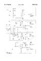
- FIG. 1is a schematic circuit diagram of the control knob circuitry of the present invention.
- control knob circuit of the present inventionis indicated generally at 10. While this control circuit is disclosed and described herein as being part of a rotary knob thermostat used in a household range oven, to be positioned to select a desired oven temperature indicated on a dial, it should become apparent that this circuit is equally well suited for use with other types of knobs as well as many other applications including control knobs for other household appliances such as a washer/dryer cycle setting knob.
- Circuit 10includes four main subcircuits, the tapped potentiometer subcircuit 12, disable subcircuit 14, a current monitor 16 and a voltage monitor 18.
- Subcircuit 12includes a tapped potentiometer POT1 having a resistor R POT and a sweeper tied to ground through resistor R1, to pin ⁇ P2A/D of an on-board microprocessor ⁇ p through a junction 20 and a resistor R2, and to disable subcircuit 14.
- the microprocessor employedmay be any suitable programmable logic device known to those having skill in the art and typically used in this type of application such as that sold under model number MN155402 by Matsushita Electric Industrial Company.
- Potentiometer POT1is controlled by a user through a suitable knob 21, preferably rotatably mounted to a control panel 23 having corresponding desired oven temperatures contained thereon and mechanically coupled to the sweeper of POT1 in a manner known to those with skill in the art. Suitable mechanical coupling could also be provided to operate POT1 in conjunction with a sliding knob or knob of any other configuration in the same fashion.
- the microprocessorconverts a voltage produced by POT1 into a digital value and monitors the location of the POT1 sweeper by monitoring the variable voltage produced thereby.
- the voltage provided to the microprocessor via pin ⁇ P2A/Din conjunction with a sensor (not shown) which provides a signal indicative of the current oven temperature, is operative to control current flow to resistive oven heating elements or to an electrically actuated valve for controlling fuel flow to a gaseous burner in order to produce an oven temperature which corresponds with the position of the actuator knob as set by the user.
- the POT1 sweeperis also tied to the non-inverting input of an operational amplifier (op amp) U1 of subcircuit 14.
- op ampoperational amplifier
- the negative input of op amp U1is connected to a 5 volt (5 V) source through a resistor R3 and to ground through resistor R4.
- Op amp U1 outputis tied to separate disable circuitry (not shown) provided to turn off all relay operation, the relays being operative upon receipt of an electrical control signal to energize a heating unit in the appliance.
- Disable subcircuit 14thus provides a hardware driven redundant shutoff circuit for turning off the broil and/or bake elements independent of the microprocessor.
- R POTThe current through R POT is monitored by current monitoring subcircuit 16 to ensure POT1 does not open up.
- R POTis coupled to the negative input of op amp U2 and is powered through the output of op amp U2, through resistor R5.
- a reference voltage V REF1is fed into the non-inverting input of U2 creating the drive current for POT1.
- the U2 output to node 26is also coupled through a resistor R6 and node 28, grounded through capacitor C3, to pin ⁇ P3A/D of the microprocessor.
- the microprocessormonitors current in order to detect a breakdown due to a broken trace or other mechanical problem.
- the tap voltage of R POTis monitored by voltage monitor subcircuit 18 wherein a second reference voltage V REF2 is fed to the non-inverting input of an op amp U3, as well as through a resistor R7 to ground.
- the output from op amp U3is coupled to the negative input as well as through a resistor R8 to pin ⁇ P1A/D of the microprocessor to ensure that this tap voltage stays within a specified range, U3 being connected as a unity gain follower.
- Pin ⁇ P1A/Dis also grounded through capacitor C4.
- U3biases the tap voltage, thus fixing POT1 in order to compensate for inaccuracies such as nonlinearities therein, as well as maintain an accurate mechanical vs. electrical relationship.
- control knob circuit 10 of the present inventionprovides a reliable means for selectively energizing the heating elements in a household range oven.
- a tap voltage biaseliminates the need for expensive factory calibration while current and voltage monitoring subcircuits ensure reliable operation.
- a redundant disable subcircuitprovides an additional hardware means for shutting off oven heating elements in response to the user positioning the interconnected control knob to an OFF position.
- circuit 10For purposes of clarity the values of the components of circuit 10 have been omitted from FIG. 1, but are provided in the table below.
Landscapes
- Physics & Mathematics (AREA)
- General Physics & Mathematics (AREA)
- Engineering & Computer Science (AREA)
- Automation & Control Theory (AREA)
- Switches With Compound Operations (AREA)
Abstract
Description
______________________________________ Resistors Capacitors Other ______________________________________ R1 560 kΩ C1 0.1 μF U1 LM324 R2 10 k C2 0.1 μF U2 LM324 R3 39 k C3 0.1 μF U3 LM339 R4 1.8 k C4 0.1 μF R5 866 R6 10 k R7 560 k R8 10 k R.sub.POT 10 k ______________________________________
Claims (11)
Priority Applications (1)
| Application Number | Priority Date | Filing Date | Title |
|---|---|---|---|
| US08/790,008US5812411A (en) | 1995-07-14 | 1997-01-28 | Tapped variable potentiometer resistor with current sense and safety circuit |
Applications Claiming Priority (2)
| Application Number | Priority Date | Filing Date | Title |
|---|---|---|---|
| US50198395A | 1995-07-14 | 1995-07-14 | |
| US08/790,008US5812411A (en) | 1995-07-14 | 1997-01-28 | Tapped variable potentiometer resistor with current sense and safety circuit |
Related Parent Applications (1)
| Application Number | Title | Priority Date | Filing Date |
|---|---|---|---|
| US50198395AContinuation | 1995-07-14 | 1995-07-14 |
Publications (1)
| Publication Number | Publication Date |
|---|---|
| US5812411Atrue US5812411A (en) | 1998-09-22 |
Family
ID=23995823
Family Applications (1)
| Application Number | Title | Priority Date | Filing Date |
|---|---|---|---|
| US08/790,008Expired - Fee RelatedUS5812411A (en) | 1995-07-14 | 1997-01-28 | Tapped variable potentiometer resistor with current sense and safety circuit |
Country Status (1)
| Country | Link |
|---|---|
| US (1) | US5812411A (en) |
Cited By (10)
| Publication number | Priority date | Publication date | Assignee | Title |
|---|---|---|---|---|
| US6140619A (en)* | 1999-05-28 | 2000-10-31 | The Garland Group | Temperature control apparatus, method and memory medium for an oven |
| US6181141B1 (en)* | 1999-01-22 | 2001-01-30 | Honeywell Inc. | Failsafe monitoring system for potentiometers and monitor interface |
| EP1157707A3 (en)* | 2000-05-26 | 2003-05-28 | Ethicon | Method and composition for deforming soft tissues |
| EP1494098A1 (en)* | 2003-07-04 | 2005-01-05 | Siemens Aktiengesellschaft | Control device for safety engineering and control method |
| DE102005048601B3 (en)* | 2005-10-06 | 2007-04-05 | Pilz Gmbh & Co. Kg | Position indicator e.g. potentiometer, evaluating device for safety switching device, has microcontrollers finding measuring quantities representative for indicator`s partial impedances, and having outputs assigned with high/low potential |
| US20080100303A1 (en)* | 2006-08-10 | 2008-05-01 | Honeywell International, Inc. | Circuit and method for determining potentiometer wiper resistance |
| US20100231191A1 (en)* | 2009-03-13 | 2010-09-16 | David Scott Nyce | Method and apparatus for simulating a potentiometer |
| WO2011022049A1 (en)* | 2009-08-20 | 2011-02-24 | Standex International Corporation | Commercial toaster apparatus |
| US20140159753A1 (en)* | 2011-07-01 | 2014-06-12 | Xuanlai You | Online alternating current detection device and method |
| CN110762562A (en)* | 2018-11-07 | 2020-02-07 | 桂林航天工业学院 | A resistance type gas stove control device |
Citations (8)
| Publication number | Priority date | Publication date | Assignee | Title |
|---|---|---|---|---|
| US4012617A (en)* | 1975-07-24 | 1977-03-15 | Litton Systems, Inc. | Power controller for microwave magnetron |
| US4430540A (en)* | 1981-06-15 | 1984-02-07 | Texas Instruments Incorporated | Data input apparatus for microwave oven controllers |
| US4458140A (en)* | 1980-10-14 | 1984-07-03 | Kidde Consumer Durables Corp. | Temperature control apparatus for convection oven |
| US4864513A (en)* | 1987-07-07 | 1989-09-05 | Honeywell Incorporated | Potentiometer setting detection by measuring the ratio of RC time constants |
| US4958062A (en)* | 1989-03-07 | 1990-09-18 | Goldstar Instrument & Electric Co., Ltd. | Driving control apparatus for an electric range with self-diagnosis function |
| US4987372A (en)* | 1989-08-01 | 1991-01-22 | Lutron Electronics Co., Inc. | Potentiometer state sensing circuit |
| US5297056A (en)* | 1990-03-30 | 1994-03-22 | Dallas Semiconductor Corp. | Directly-writable digital potentiometer |
| US5323137A (en)* | 1991-03-18 | 1994-06-21 | Aisin Seiki Kabushiki Kaisha | Potentiometer |
- 1997
- 1997-01-28USUS08/790,008patent/US5812411A/ennot_activeExpired - Fee Related
Patent Citations (8)
| Publication number | Priority date | Publication date | Assignee | Title |
|---|---|---|---|---|
| US4012617A (en)* | 1975-07-24 | 1977-03-15 | Litton Systems, Inc. | Power controller for microwave magnetron |
| US4458140A (en)* | 1980-10-14 | 1984-07-03 | Kidde Consumer Durables Corp. | Temperature control apparatus for convection oven |
| US4430540A (en)* | 1981-06-15 | 1984-02-07 | Texas Instruments Incorporated | Data input apparatus for microwave oven controllers |
| US4864513A (en)* | 1987-07-07 | 1989-09-05 | Honeywell Incorporated | Potentiometer setting detection by measuring the ratio of RC time constants |
| US4958062A (en)* | 1989-03-07 | 1990-09-18 | Goldstar Instrument & Electric Co., Ltd. | Driving control apparatus for an electric range with self-diagnosis function |
| US4987372A (en)* | 1989-08-01 | 1991-01-22 | Lutron Electronics Co., Inc. | Potentiometer state sensing circuit |
| US5297056A (en)* | 1990-03-30 | 1994-03-22 | Dallas Semiconductor Corp. | Directly-writable digital potentiometer |
| US5323137A (en)* | 1991-03-18 | 1994-06-21 | Aisin Seiki Kabushiki Kaisha | Potentiometer |
Cited By (14)
| Publication number | Priority date | Publication date | Assignee | Title |
|---|---|---|---|---|
| US6181141B1 (en)* | 1999-01-22 | 2001-01-30 | Honeywell Inc. | Failsafe monitoring system for potentiometers and monitor interface |
| US6140619A (en)* | 1999-05-28 | 2000-10-31 | The Garland Group | Temperature control apparatus, method and memory medium for an oven |
| EP1157707A3 (en)* | 2000-05-26 | 2003-05-28 | Ethicon | Method and composition for deforming soft tissues |
| EP1494098A1 (en)* | 2003-07-04 | 2005-01-05 | Siemens Aktiengesellschaft | Control device for safety engineering and control method |
| DE102005048601B3 (en)* | 2005-10-06 | 2007-04-05 | Pilz Gmbh & Co. Kg | Position indicator e.g. potentiometer, evaluating device for safety switching device, has microcontrollers finding measuring quantities representative for indicator`s partial impedances, and having outputs assigned with high/low potential |
| US7705492B2 (en) | 2005-10-06 | 2010-04-27 | Pilz Gmbh & Co. Kg | Arrangement for failsafe evaluation of a position encoder |
| US7550981B2 (en) | 2006-08-10 | 2009-06-23 | Honeywell International Inc. | Circuit and method for determining potentiometer wiper resistance |
| US20080100303A1 (en)* | 2006-08-10 | 2008-05-01 | Honeywell International, Inc. | Circuit and method for determining potentiometer wiper resistance |
| US20100231191A1 (en)* | 2009-03-13 | 2010-09-16 | David Scott Nyce | Method and apparatus for simulating a potentiometer |
| US8077067B2 (en)* | 2009-03-13 | 2011-12-13 | David Scott Nyce | Method and apparatus for simulating a potentiometer |
| WO2011022049A1 (en)* | 2009-08-20 | 2011-02-24 | Standex International Corporation | Commercial toaster apparatus |
| US20140159753A1 (en)* | 2011-07-01 | 2014-06-12 | Xuanlai You | Online alternating current detection device and method |
| US9279833B2 (en)* | 2011-07-01 | 2016-03-08 | Xuanlai You | Online alternating current detection device and method |
| CN110762562A (en)* | 2018-11-07 | 2020-02-07 | 桂林航天工业学院 | A resistance type gas stove control device |
Similar Documents
| Publication | Publication Date | Title |
|---|---|---|
| US5812411A (en) | Tapped variable potentiometer resistor with current sense and safety circuit | |
| CA1218438A (en) | Temperature control system | |
| CA1301287C (en) | Electronic programmable thermostat | |
| KR100743799B1 (en) | Electronic mixed water production device and mixed water production method | |
| US5662465A (en) | Controlling flow of fuel gas to a burner | |
| US5611484A (en) | Thermostat with selectable temperature sensor inputs | |
| US4669654A (en) | Electronic programmable thermostat | |
| US7123823B2 (en) | Programmable manual hair dryer with multiple functions | |
| US4361274A (en) | Electronic temperature control | |
| US6772018B2 (en) | Control system apparatus and method using a controlled device for manual data entry | |
| JPH0387517A (en) | Gas burner controller and controlling method of gas burner valve | |
| US4531064A (en) | Electronic thermostat with repetitive operation cycle | |
| US4549527A (en) | Solid state temperature controller | |
| CA2031876A1 (en) | Electronic control system for an oven | |
| CA2191170A1 (en) | Damper actuator controller having an enthalpy sensor input | |
| US5205486A (en) | Control device for combustion apparatus and method for controlling the same | |
| GB2433886A (en) | A programmable hair dryer | |
| US5528017A (en) | Electronic thermostat for an oven | |
| US4378523A (en) | Metering and control system | |
| CA2391688C (en) | Electronic power control for cooktop heaters | |
| EP0636954A1 (en) | An electronic control board for boilers | |
| AU711388B2 (en) | Method and apparatus for the control of flammable fluid heating apparatus | |
| CA2525344A1 (en) | Programmable manual hair dryer with multiple functions | |
| JPH0320518A (en) | Combustion controller | |
| US11255566B2 (en) | Method and system for changing a flow rate of air out of a duct in a HVAC system |
Legal Events
| Date | Code | Title | Description |
|---|---|---|---|
| AS | Assignment | Owner name:RANCO INCORPORATED OF DELAWARE, DELAWARE Free format text:ASSIGNMENT OF ASSIGNORS INTEREST;ASSIGNOR:EATON CORPORATION;REEL/FRAME:010473/0875 Effective date:19971130 | |
| FPAY | Fee payment | Year of fee payment:4 | |
| AS | Assignment | Owner name:DEUTSCHE BANK AG, LONDON, UNITED KINGDOM Free format text:SECURITY INTEREST;ASSIGNOR:RANCO INCORPORATED OF DELAWARE;REEL/FRAME:015320/0126 Effective date:20040504 | |
| FPAY | Fee payment | Year of fee payment:8 | |
| AS | Assignment | Owner name:RANCO INCORPORATED OF DELAWARE, DELAWARE Free format text:RELEASE AND TERMINATION OF SECURITY INTEREST;ASSIGNOR:DEUTSCHE BANK AG, LONDON BRANCH;REEL/FRAME:018026/0953 Effective date:20060713 | |
| REMI | Maintenance fee reminder mailed | ||
| LAPS | Lapse for failure to pay maintenance fees | ||
| LAPS | Lapse for failure to pay maintenance fees | Free format text:PATENT EXPIRED FOR FAILURE TO PAY MAINTENANCE FEES (ORIGINAL EVENT CODE: EXP.); ENTITY STATUS OF PATENT OWNER: LARGE ENTITY | |
| STCH | Information on status: patent discontinuation | Free format text:PATENT EXPIRED DUE TO NONPAYMENT OF MAINTENANCE FEES UNDER 37 CFR 1.362 | |
| FP | Lapsed due to failure to pay maintenance fee | Effective date:20100922 |