US5812383A - Low power stand-by for switched-mode power supply circuit with burst mode operation - Google Patents
Low power stand-by for switched-mode power supply circuit with burst mode operationDownload PDFInfo
- Publication number
- US5812383A US5812383AUS08/903,779US90377997AUS5812383AUS 5812383 AUS5812383 AUS 5812383AUS 90377997 AUS90377997 AUS 90377997AUS 5812383 AUS5812383 AUS 5812383A
- Authority
- US
- United States
- Prior art keywords
- voltage
- mode
- stand
- output
- switched
- Prior art date
- Legal status (The legal status is an assumption and is not a legal conclusion. Google has not performed a legal analysis and makes no representation as to the accuracy of the status listed.)
- Expired - Lifetime
Links
- 239000003990capacitorSubstances0.000claimsabstractdescription73
- 238000004804windingMethods0.000claimsabstractdescription73
- 230000008878couplingEffects0.000claimsdescription8
- 238000010168coupling processMethods0.000claimsdescription8
- 238000005859coupling reactionMethods0.000claimsdescription8
- 238000000034methodMethods0.000claimsdescription6
- 230000001276controlling effectEffects0.000claimsdescription4
- 230000001105regulatory effectEffects0.000claimsdescription3
- 238000010586diagramMethods0.000description9
- 238000012986modificationMethods0.000description2
- 230000004048modificationEffects0.000description2
- 230000003213activating effectEffects0.000description1
- 230000004075alterationEffects0.000description1
- 230000005347demagnetizationEffects0.000description1
- 238000001514detection methodMethods0.000description1
- 230000000694effectsEffects0.000description1
- 230000009467reductionEffects0.000description1
- 230000004044responseEffects0.000description1
- 238000004904shorteningMethods0.000description1
Images


Classifications
- H—ELECTRICITY
- H02—GENERATION; CONVERSION OR DISTRIBUTION OF ELECTRIC POWER
- H02M—APPARATUS FOR CONVERSION BETWEEN AC AND AC, BETWEEN AC AND DC, OR BETWEEN DC AND DC, AND FOR USE WITH MAINS OR SIMILAR POWER SUPPLY SYSTEMS; CONVERSION OF DC OR AC INPUT POWER INTO SURGE OUTPUT POWER; CONTROL OR REGULATION THEREOF
- H02M3/00—Conversion of DC power input into DC power output
- H02M3/22—Conversion of DC power input into DC power output with intermediate conversion into AC
- H02M3/24—Conversion of DC power input into DC power output with intermediate conversion into AC by static converters
- H02M3/28—Conversion of DC power input into DC power output with intermediate conversion into AC by static converters using discharge tubes with control electrode or semiconductor devices with control electrode to produce the intermediate AC
- H02M3/325—Conversion of DC power input into DC power output with intermediate conversion into AC by static converters using discharge tubes with control electrode or semiconductor devices with control electrode to produce the intermediate AC using devices of a triode or a transistor type requiring continuous application of a control signal
- H02M3/335—Conversion of DC power input into DC power output with intermediate conversion into AC by static converters using discharge tubes with control electrode or semiconductor devices with control electrode to produce the intermediate AC using devices of a triode or a transistor type requiring continuous application of a control signal using semiconductor devices only
- H02M3/33507—Conversion of DC power input into DC power output with intermediate conversion into AC by static converters using discharge tubes with control electrode or semiconductor devices with control electrode to produce the intermediate AC using devices of a triode or a transistor type requiring continuous application of a control signal using semiconductor devices only with automatic control of the output voltage or current, e.g. flyback converters
- H02M3/33523—Conversion of DC power input into DC power output with intermediate conversion into AC by static converters using discharge tubes with control electrode or semiconductor devices with control electrode to produce the intermediate AC using devices of a triode or a transistor type requiring continuous application of a control signal using semiconductor devices only with automatic control of the output voltage or current, e.g. flyback converters with galvanic isolation between input and output of both the power stage and the feedback loop
- H—ELECTRICITY
- H02—GENERATION; CONVERSION OR DISTRIBUTION OF ELECTRIC POWER
- H02M—APPARATUS FOR CONVERSION BETWEEN AC AND AC, BETWEEN AC AND DC, OR BETWEEN DC AND DC, AND FOR USE WITH MAINS OR SIMILAR POWER SUPPLY SYSTEMS; CONVERSION OF DC OR AC INPUT POWER INTO SURGE OUTPUT POWER; CONTROL OR REGULATION THEREOF
- H02M1/00—Details of apparatus for conversion
- H02M1/0003—Details of control, feedback or regulation circuits
- H02M1/0032—Control circuits allowing low power mode operation, e.g. in standby mode
- Y—GENERAL TAGGING OF NEW TECHNOLOGICAL DEVELOPMENTS; GENERAL TAGGING OF CROSS-SECTIONAL TECHNOLOGIES SPANNING OVER SEVERAL SECTIONS OF THE IPC; TECHNICAL SUBJECTS COVERED BY FORMER USPC CROSS-REFERENCE ART COLLECTIONS [XRACs] AND DIGESTS
- Y02—TECHNOLOGIES OR APPLICATIONS FOR MITIGATION OR ADAPTATION AGAINST CLIMATE CHANGE
- Y02B—CLIMATE CHANGE MITIGATION TECHNOLOGIES RELATED TO BUILDINGS, e.g. HOUSING, HOUSE APPLIANCES OR RELATED END-USER APPLICATIONS
- Y02B70/00—Technologies for an efficient end-user side electric power management and consumption
- Y02B70/10—Technologies improving the efficiency by using switched-mode power supplies [SMPS], i.e. efficient power electronics conversion e.g. power factor correction or reduction of losses in power supplies or efficient standby modes
Definitions
- the subject inventionrelates to switched-mode power supply circuits for television receivers, in which during a stand-by mode, the switched-mode power supply circuit exhibits a burst mode operation.
- FIG. 46The above type of switched-mode power supply circuit is shown in FIG. 46 of the applications for a Mixed Frequency Mode Green PWM Controller No. MC44603, made by Motorola, Inc.
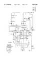
- FIG. 1herein shows the essential portions of this switched-mode power supply circuit.
- the switched-mode power supply circuitincludes a switching transistor Tr1 having a drain connected to the primary winding L1 of a transformer T, and an source connected through a resistor R1 to ground.
- the other end of winding L1is connected to a positive terminal +V B of a line voltage rectifier LVR.
- the gate of transistor Tr1is connected through a resistor R2 to the output (pin 3) of the Controller.
- the transformerhas secondary windings L2 and L3 which are, in part, connected to a light emitting diode D1 of an opto-coupler OC.
- An input terminal of the line voltage rectifier LVRis connected to a filter circuit, including a series resistor R3 and a capacitor C1 connected to ground, this filter circuit then being connected, via respective resistors R4, R5 and R6, to the Vcc input (pin 1), the Vc input (pin 2) and foldback input (pin 5) of the Controller, and to a light sensing transistor Tr2 of the opto-coupler OC.
- the filter circuitis also connected, via a series arrangement of a diode D2 and an inductor L4, to one terminal of an auxiliary primary winding L aux , of the transformer T, to the demagnetization detection input (pin 8) of the Controller via a filter circuit including a series resistor R7 and a capacitor C2 connected to ground, and to the over-voltage protection input (pin 6) of the Controller via the series arrangement of a diode D3 and a resistor R8, the pin 6 being shunted to ground by a capacitor C3, the resistor R8 being connected to ground (also to pin 4 of the Controller) via a resistor R9.
- a switched-mode power supply circuithaving an operating mode and a stand-by mode
- said switched-mode power supply circuitcomprising means for generating a d.c. supply voltage having a first output terminal and a second output terminal; a transformer having a primary winding, an auxiliary primary winding, a first secondary winding and a second secondary winding, said primary winding having a first terminal coupled to the first output terminal of said generating means and a second terminal; a controllable switch connected in a series with the second terminal of said primary winding and the second output terminal of said generating means; a main output capacitor coupled across output terminals of said first secondary winding for providing a first main output voltage in the operating state and a second main output voltage in the stand-by mode, said second main output voltage being lower than said first main output voltage; a control output capacitor coupled across output terminals of said second secondary winding for providing a control output voltage; means for selectively coupling one of the output terminals of said first secondary winding to said second secondary winding during said
- the first secondary windingwhen stand-by mode is desired, the first secondary winding is connected to the second secondary winding removing energy from the main output capacitor and as such, the second main output voltage is generated across the main output capacitor.
- the light emitting means of the opto-coupleris coupled across the control output capacitor. Due to the coupling of the first secondary winding to the second secondary winding, the control output voltage across the control output capacitor increases until it reaches a first predetermined value. At this point, the light emitting means activates the light detecting means of the opto-coupler causing the auxiliary voltage across the auxiliary capacitor to be applied to the stand-by mode detecting input of the controller.
- the controllerUpon detecting the auxiliary voltage, the controller turns off the controllable switch causing the transformer to stop transferring energy from the primary winding to the first and second secondary windings and the auxiliary winding.
- the control output capacitorthen begins to drain causing the voltage across the control output capacitor to drop.
- the auxiliary capacitorbegins to drain causing the voltage across the auxiliary capacitor to drop.
- the control output voltagedrops below the first predetermined value
- the light emitting means of the opto-couplerceases to generate light and the light detecting means turns off thereby removing the auxiliary voltage from the stand-by mode detecting input of the controller.
- the start-up current source in the controlleris activated which applies a current to charge the auxiliary capacitor.
- the controllerturns off the start-up current source and causes the controllable switch to re-commence switching, and the cycle repeats.
- control output capacitoris required in order to maintain the control voltage when returning the switched-mode power supply to normal operation after burst mode stand-by operation.
- start-up current sourceit is advantageous for the start-up current source to generate a larger than normal current for charging up the auxiliary capacitor during the last cycle in the burst mode stand-by operation.
- a further object of the present inventionis to provide a switched-mode power supply circuit which is capable of operating in a burst mode during stand-by and which generates a minimum of audible noise.
- said switched-mode power supply circuitfurther comprises a sense resistor connected in series between said controllable switch and said second output terminal of said generating means, and said controller further comprises means for generating a measuring current; means for selectively applying said measuring current to said sense resistor during times when said controllable switch is not switching; means for measuring a voltage across said sense resistor generated by said measuring current; means for selecting a reference voltage based on said measured voltage; and means for controlling said controllable switch based on a comparison of a voltage across said sense resistor when said controllable switch is switching and said reference voltage.
- FIG. 1shows a schematic diagram of a prior art switched-mode power supply circuit having a trickle charge circuit
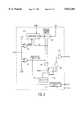
- FIG. 2shows a schematic block diagram of a first embodiment of a switched-mode power supply circuit according to the subject invention
- FIG. 3shows a schematic block diagram of a second embodiment of a switched-mode power supply circuit according to the subject invention
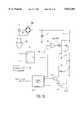
- FIG. 4shows a block diagram of the start-up current source and Vcc management circuit as well as the over-current protection circuit contained in the controller;
- FIG. 5shows a schematic diagram of the start-up current source
- FIG. 6shows a block diagram of the Vcc management circuit
- FIG. 7is a graph showing the current I AUX with respect to the voltage V AUX ;
- FIG. 8is a graph showing the voltage V AUX with respect to time
- FIG. 9is a detailed block diagram of a first embodiment of the over-current protection circuit.
- FIG. 10is a detailed block diagram of a second embodiment of the over-current protection circuit.
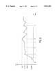
- FIG. 11is a graph showing the voltage across the control output capacitor, V AUX , burst mode signal S6, and the drive signal.
- FIG. 2shows a schematic block diagram of a first embodiment of the switched-mode power supply according to the subject invention using primary control.
- a diode rectifier bridge RECis connected to a line voltage source.
- An output from the rectifier bridge RECis connected to ground through a capacitor C11 and to one end of a primary winding L11 of a transformer TR.
- the other end of primary winding L11is connected to one terminal of a controllable switch Tr11, the other terminal of which being connected to ground through a sense resistor R SENSE .
- a first secondary winding L12 of the transformer TRhas a first end and a second end connected to each other through a series arrangement of a diode D11 and a main output capacitor C12, the second end of the first secondary winding L12 also being connected to ground.
- a load(not shown) may be connected across the main output capacitor C12.
- the transformer TRalso includes a second secondary winding L13 having a first end and a second end connected to each other through a series arrangement of a diode D12 and a control output capacitor C13, the second end of the second secondary winding L13 also being connected to ground.
- a microprocessor(not shown), for controlling, for example, a television receiver in which the switched-mode power supply circuit is installed, is connected across the control output capacitor C13 to receive operating power.
- the first end of the first secondary winding L12is also connected via a diode D13 and a controllable switch Sw1 to one end of the control output capacitor C13, while the control output capacitor C13 is shunted by a series arrangement of a light emitting diode D14 of an opto-coupler, a Zener diode Z1 and a controllable switch Sw2.
- the controllable switches Sw1 and Sw2are controlled by a signal from the microprocessor to initiate the stand-by mode of the switched-mode power supply circuit.
- the transformer TRfurther includes an auxiliary primary winding L14 which has one end connected to a diode D15, and then to ground through a V AUX capacitor C14, to a V AUX input of a controller IC, and to one terminal of a light sensor Tr12 of the opto-coupler, the other terminal of the light sensor Tr12 being connected to ground via resistor R11, and to a stand-by mode detecting input (OOB) of the controller IC.
- a series arrangement of two resistors, R12 and R13, and a Zener diode Z2connect the output of the rectifier bridge REC to ground.
- the junction between resistor R13 and Zener diode Z2is connected to the OOB input via a power switch Sw3.
- the other end of the auxiliary primary winding L14is connected to ground.
- the controller ICalso has a V IN input connected to the output of the rectifier bridge REC, a DEMAG input connected through a resistor R14 to the one end of the auxiliary primary winding L14, a driver output connected to the control input of controllable switch Tr11, and an I SENSE input connected to the resistor R SENSE .
- FIG. 2uses a separate opto-coupler in primary sensing to signal the controller IC that burst mode stand-by is desired.
- an opto-coupleris already being used to regulate the control voltage during normal operation.
- FIG. 3shows a second embodiment of the switched-mode power supply circuit of the subject invention in which the already existing opto-coupler is additionally used in secondary sensing to signal burst mode stand-by operation.
- the light emitting diode D14 of the opto-coupleris connected through resistors R15 and R16 to the anode of a Zener diode Z3, the cathode of which being connected to ground.
- a series combination of a resistor R17 and a capacitor C15connects the anode of the Zener diode Z3 to a control terminal of the Zener diode Z3 and to junction point between resistors R18 and R19 connected between the output of the first secondary winding L12 and ground.
- Switch Sw2connects the anode of Zener diode Z1 to the output of the second secondary winding L13, the cathode of Zener diode Z1 being connected to ground through the series arrangement of resistors R20 and R21.
- the junction between resistors R15 and R16is connected to the collector of an NPN transistor Tr13, having an emitter connected to ground and a base connected to the junction between resistors R20 and R21.
- the junction between the light sensor Tr12 of the opto-coupler and the diode D16is further connected through a resistor R22 to a V CNTL input of the controller IC which is also connected to ground through the parallel arrangement of a resistor R23 and a capacitor C16.
- transistor Tr13is off and the intensity of the light being emitted by the light emitting diode D14 of the opto-coupler is controlled by the circuit R16-R19, C15 and Z3.
- This variable light intensitycauses a corresponding response in the light sensor Tr12 which applies a portion of the V AUX voltage to the V CNTL input of the controller IC for regulating the controllable switch Tr11, this voltage being less than the +5.6 volts enabling the comparator 36.
- transistor Tr13turns on causing the light emitting diode D14 to emit a much increased light output, which in turn causes the light sensor Tr12 to apply the whole of the V AUX voltage to the OOB input of the controller IC.
- the controller ICincludes a start-up current source 30 coupled to the V IN input and a Vcc management circuit 32 connected to the V AUX input.
- the OOB inputis connected to a first comparator 34 for comparing the voltage thereon to +2.4V, and generates an "OFF/ON" signal. This OFF/ON signal is applied to an input of the Vcc management circuit 32.
- the OOB inputis also connected to a second comparator 36 for comparing the voltage thereon to +5.6V, for generating a "Burst Mode Stand-by" signal S6. This signal S6 is applied to the start-up current source 30 and to one input of an OR-gate 38.
- An output (S5) from the Vcc management circuit 32is also applied to the start-up current source 30 and to an inverting input of OR-gate 38.
- An output from OR-gate 38is applied to the reset input of an RS flip-flop 40, the set input being connected to an output of an oscillator 42.
- the Q output from the RS flip-flop 40is connected to one input of an AND-gate 44 which has an output connected to a driver 46 for driving the controllable switch Tr11.
- FIG. 5shows an embodiment of the start-up current source 30.
- the V INis connected to a high voltage switch JFET.
- the gate of JFETis grounded and as such, the JFET is always on.
- the voltage at the source of JFETis approximately equal to the pinch-off voltage of the JFET.
- Resistor R24limits the current, and Zener diodes Z4 and Z5 are used to provide gate voltages for FET switches M3 and M4.
- the source of FET switch M4is connected to PMOS current sources 50 while corresponding NMOS current sources 52 are connected to ground.
- the NMOS current sources 52receive a bias current I BIAS .
- V AUX inputis connected, via diode D17 to the source of FET switch M3, which is also connected to receive the voltage Vcc.
- the gates of FET switches M1 and M2are connected to receive the signal S5 and selectively connect the gates of FET switches M3 and M4, respectively, to ground.
- the PMOS current sources 50 and the NMOS current sources 52are selectively interconnected by controllable switches Sw5-Sw9 which receive the switching signals S1-S4 and S7. Depending on which of the switches Sw5-Sw9 are closed, various currents (I1-I5) are applied to the V AUX input.
- the signal S6activates controllable switch Sw4 which suspends operation of the start-up current source 30. When not in use, the start-up current source 30 is turned off, to minimize wasteful dissipation, by the signal S5 turning on FET switches M1 and M2.
- the switching signals S1-S5 and S7are generated by the Vcc management circuit 32.
- the V AUX inputis connected to one input of comparators 54-60, which compare the V AUX voltage to reference voltages V1-V4 representing the over-voltage protection level (e.g., +14V), the start voltage (e.g., +11V), the under-voltage lock-out level (e.g., +8V), and the Vcc low voltage level.
- the outputs from the comparators 54-60are applied to respective inputs of a logic circuit 62 which then generates the switching signals S1-S5, S7 and UVLO.
- the logic circuit 62further receives the OFF/ON signal from the comparator 34.
- the controller IC(at t 2 ⁇ t ⁇ t 4 ) now starts causing the controllable switch Tr11 to switch which then causes the transformer TR to start transferring energy from the primary winding L11 to the secondary windings L12 and L13, and also to the auxiliary primary winding L14 which then takes over supplying the V AUX capacitor C14.
- the switched-mode power supply circuitis now in normal operation and the start-up current source 30 is turned off by the S5 signal from the Vcc management circuit 32.
- the microprocessorcloses switches Sw1 and Sw2 thereby coupling the first secondary winding L12 to the second secondary winding L13 thereby removing energy from the main output capacitor C12.
- switch Sw2connects the light emitting diode D14 of the opto-coupler and the Zener diode Z1 across the second secondary winding L13.
- the coupling of the first and second secondary windings L12 and L13now causes an increase in the control output voltage across the control output capacitor C13.
- the control output voltageexceeds the Zener diode Z1 voltage
- the light emitting diode D14is energized. This causes the light sensor Tr12 to couple the V AUX voltage to the OOB input of the controller IC. Since the V AUX voltage is in excess of, for example, +5.6V, the comparator 36 generates the signal S6 resetting the flip-flop 40 which stops the controllable switch Tr11 from switching.
- transformer TRceases transferring energy form the primary winding L11 to the first and second secondary windings L12 and L13 and to the auxiliary primary winding L14.
- the control output capacitor C13 and the V AUX capacitor C14begin to drain causing the control voltage and the V AUX voltage to begin to drop.
- the light emitting diode D14stops emitting light
- the light sensor Tr12removes the V AUX voltage from input OOB of the controller IC, and the comparator 36 stops generating the signal S6.
- the Vcc management circuit 32stops generating the signal S5 thereby maintaining the reset condition of the flip-flop 40, and activating the start-up current source 30 for charging up the V AUX capacitor C14 thereby raising the V AUX voltage.
- the Vcc management circuit 32generates the S5 signal which turns off the start-up current source 30 and allows the controllable switch Tr11 to commence switching.
- the switching of the controllable switch Tr11allows the transformer TR to transfer energy from the primary winding L11 to the first and second secondary windings L13. This cycle then repeats itself until the microprocessor opens switches Sw1 and Sw2 indicating an end to the burst mode stand-by operation and a return to normal operation.
- a disadvantage of burst mode stand-by operationis that a relatively large capacitance is required for the control output capacitor C13 during burst mode operation.
- the size of the control output capacitoris determined by the last two cycles during burst mode stand-by operation. In particular, during the last two cycles, the control output capacitor C13 is not recharged and its voltage continues to drop. The control output capacitor C13 must then have a large enough capacitance to ensure sufficient supply for the microprocessor connected across the control output capacitor C13 during this time.
- the start-up current source 30is modified to supply the current I5 to the V AUX capacitor C14 during the time period T5 (see FIG. 11) which has the effect of significantly shortening the time period T5. It should be noted that FIG. 11 is not drawn to scale and that in fact, the time period T3 is actually much smaller than T5.
- the controller ICincludes an over-current protection circuit 48 which detects the current through the controllable switch Tr11.
- the over-current protection circuit 48has inputs coupled to the I SENSE and DEMAG inputs of the controller IC, and receives the S6 signal from the comparator 36.
- An output from the over-current protection circuit 48is coupled to a second input of the AND-gate 44.
- FIG. 8An embodiment of this over-current protection circuit 48 is shown in FIG. 8.
- a plurality of comparators 60-68compare the voltage on the I SENSE input to voltage references V REF1 -V REF5 , and apply their output signals to logic circuit 70, which receives the DEMAG signal and the S6 signal.
- the logic circuit 70closes one of the switches Sw10-Sw14 connecting a respective voltage (100 mV-500 mV) as a reference voltage to the non-inverting input of an over-current protection (OCP) comparator 72 to which the voltage on the I SENSE input is applied to the inverting input.
- An output current I OUT from a current source 74is selectively applied to the I SENSE line by a switch Sw15 controlled by the S6 signal.
- Peak currentis ordinarily set by choosing the value of the resistor R SENSE depending on the demands of the system. However, this is a parameter which is set at the time of system design and cannot be changed depending on the state of the system (i.e., normal or burst mode stand-by operation).
- the over-current protection circuit 48measures the value of R SENSE which, in turn, reflects the peak current selected for that particular system.
- the reference trip level for the OCP comparator 72is adjusted to bring down the peak current level below 1 ampere. This is accomplished by sending out a fixed current I OUT from the I SENSE input into the R SENSE resistor when the controllable switch Tr11 is not switching (during the occurrence of signal S6), and measuring the voltage:
- V SENSEis a direct measure of I PEAK .
- a new reference voltageis selected for the OCP comparator 72. This new reference voltage is then used during the next cycle of switching by the controllable switch Tr11.
- a SenseFETmay be used to implement peak current reduction in an integrated power IC (PIC).
- PICintegrated power IC
- a SenseFETis a smaller power transistor which is arranged in parallel with the main controllable switch Tr11. As the SenseFET is driven with the same gate drive waveform and has the same drain voltage as the controllable switch Tr11, the current through the SenseFET will be a true representation of the current through the main controllable switch Tr11.
- the I SENSE inputis connected to the inverting input of an OCP comparator 80 which receives a reference voltage of 500 mV at its non-inverting input.
- An output from the OCP comparator 80is applied to one input of a logic circuit 82 which receives the burst mode stand-by signal S6.
- the source of the SenseFETis connected to ground via a resistor 84 and to the inverting input of a comparator 86 which has its non-inverting input connected to a voltage source V REF .
- An output from the comparator 86is connected to a second input of the logic circuit 82.
- the resistance of resistor 84 and the value of V REFare set for a peak current of 1 amp.
- the over-current protection functionis taken over by the comparator 86 instead of the OCP comparator 80, thus setting the peak current level to 1 amp. instead of at the level as determined by the R SENSE resistor as measured by the OCP comparator 80.
Landscapes
- Engineering & Computer Science (AREA)
- Power Engineering (AREA)
- Dc-Dc Converters (AREA)
- Television Receiver Circuits (AREA)
Abstract
Description
V.sub.SENSE =I.sub.OUT *R.sub.SENSE
R.sub.SENSE =(500 mV)/I.sub.PEAK
V.sub.SENSE =(I.sub.OUT *500 mV)I.sub.PEAK
Claims (8)
Priority Applications (5)
| Application Number | Priority Date | Filing Date | Title |
|---|---|---|---|
| US08/903,779US5812383A (en) | 1997-07-31 | 1997-07-31 | Low power stand-by for switched-mode power supply circuit with burst mode operation |
| JP51072399AJP4315296B2 (en) | 1997-07-31 | 1998-07-27 | Burst mode operation for switched mode power supply circuit Low power standby |
| DE69837525TDE69837525T2 (en) | 1997-07-31 | 1998-07-27 | BURST MODE STANDBY OPERATION WITH LOW POWER CONSUMPTION FOR SWITCHING POWER SUPPLY |
| EP98932459AEP0935843B1 (en) | 1997-07-31 | 1998-07-27 | Low power stand-by for switched-mode power supply circuit with burst mode operation |
| PCT/IB1998/001138WO1999007062A2 (en) | 1997-07-31 | 1998-07-27 | Low power stand-by for switched-mode power supply circuit with burst mode operation |
Applications Claiming Priority (1)
| Application Number | Priority Date | Filing Date | Title |
|---|---|---|---|
| US08/903,779US5812383A (en) | 1997-07-31 | 1997-07-31 | Low power stand-by for switched-mode power supply circuit with burst mode operation |
Publications (1)
| Publication Number | Publication Date |
|---|---|
| US5812383Atrue US5812383A (en) | 1998-09-22 |
Family
ID=25418058
Family Applications (1)
| Application Number | Title | Priority Date | Filing Date |
|---|---|---|---|
| US08/903,779Expired - LifetimeUS5812383A (en) | 1997-07-31 | 1997-07-31 | Low power stand-by for switched-mode power supply circuit with burst mode operation |
Country Status (5)
| Country | Link |
|---|---|
| US (1) | US5812383A (en) |
| EP (1) | EP0935843B1 (en) |
| JP (1) | JP4315296B2 (en) |
| DE (1) | DE69837525T2 (en) |
| WO (1) | WO1999007062A2 (en) |
Cited By (121)
| Publication number | Priority date | Publication date | Assignee | Title |
|---|---|---|---|---|
| US5953219A (en)* | 1997-11-06 | 1999-09-14 | Murata Manufacturing Co., Ltd. | Control circuit power supply circuit and power supply circuit including same |
| US5959371A (en)* | 1995-10-31 | 1999-09-28 | Cardiac Pacemakers, Inc. | Power management system for an implantable device |
| US5982640A (en)* | 1998-02-03 | 1999-11-09 | Philips Electronics North America Corporation | Arrangement for reducing the effects of capacitive coupling in a control circuit for a switched-mode power supply |
| US5986897A (en)* | 1998-06-29 | 1999-11-16 | Philips Electronics North America Corporation | Switched-mode power supply having a circuit arrangement for turning the switching device when a voltage on the switching device is at a minimum |
| EP0930690A3 (en)* | 1998-01-16 | 1999-11-17 | Siemens Aktiengesellschaft | Switched mode power supply |
| US5995388A (en)* | 1996-01-12 | 1999-11-30 | Siemens Aktiengesellschaft | Switched-mode power supply with low power loss standby operation |
| US5995384A (en)* | 1997-07-31 | 1999-11-30 | Philips Electronics North America Corporation | Functional on/off switch for switched-mode power supply circuit with burst mode operation |
| US6002598A (en)* | 1997-04-25 | 1999-12-14 | U.S. Philips Corporation | Switched-mode power supply having an improved start-up circuit |
| US6026001A (en)* | 1997-03-08 | 2000-02-15 | Samsung Electronics Co., Ltd. | Power supplying device in primary side of power circuit |
| JP2000188728A (en)* | 1998-10-19 | 2000-07-04 | Thomson Consumer Electronics Inc | Power supply device for video device |
| WO2000062408A1 (en)* | 1999-04-12 | 2000-10-19 | Semiconductor Components Industries, L.L.C. | Regulator for switching power converter having a dual mode feedback |
| US6144566A (en)* | 1996-11-13 | 2000-11-07 | Thomson Licensing, S.A. | Standby power supply for video display apparatus |
| WO2000070730A1 (en)* | 1999-05-14 | 2000-11-23 | Koninklijke Philips Electronics N.V. | Switched-mode power supply |
| US6157549A (en)* | 1999-10-22 | 2000-12-05 | Thomson Licensing S.A. | Power supply with multiple mode operation |
| EP1058375A1 (en)* | 1999-06-01 | 2000-12-06 | Motorola, Inc. | PWM controller |
| EP1058374A1 (en)* | 1999-06-01 | 2000-12-06 | Motorola, Inc. | PWM control apparatus |
| US6185112B1 (en)* | 1998-01-28 | 2001-02-06 | Murata Manufacturing Co., Ltd. | Switching power supply having a frequency limiting circuit |
| US6188587B1 (en)* | 1998-05-16 | 2001-02-13 | Samsung Electronics Co., Ltd. | Switching mode power supply having reduced switching losses in standby mode |
| US6198639B1 (en)* | 1997-12-22 | 2001-03-06 | Siemens Aktiengesellschaft | Circuit configuration and method for producing a constant output voltage in converters |
| US6233165B1 (en)* | 2000-05-15 | 2001-05-15 | Asic Advantage, Inc. | Power converter having a low voltage regulator powered from a high voltage source |
| US6282107B1 (en)* | 2000-03-07 | 2001-08-28 | Vlt Corporation | Integrated sense and switch circuitry for transformer core resetting |
| US6285566B1 (en)* | 1998-02-09 | 2001-09-04 | Murata Manufacturing Co., Ltd. | RCC power supply with remote disabling of oscillation frequency control |
| US6366479B1 (en)* | 1999-11-16 | 2002-04-02 | Sanken Electric Co., Ltd. | DC-DC converter with reduced energy loss under lowered load impedance |
| US6370040B2 (en)* | 2000-02-25 | 2002-04-09 | Murata Manufacturing Co., Ltd. | Switching power supply apparatus having plural outputs and plural output voltage detection |
| WO2002061915A1 (en)* | 2001-02-01 | 2002-08-08 | E.G.O. Control Systems Gmbh & Co. Kg | Electric circuit arrangement |
| US6433443B2 (en)* | 2000-01-11 | 2002-08-13 | Murata Manufacturing Co., Ltd. | Switching power supply having two or more DC outputs with switching circuit provided between the outputs |
| US20020120302A1 (en)* | 1999-04-30 | 2002-08-29 | Cardiac Pacemakers, Inc. | Implantable cardiac stimulating device with optimized demand |
| US6456511B1 (en)* | 2000-02-17 | 2002-09-24 | Tyco Electronics Corporation | Start-up circuit for flyback converter having secondary pulse width modulation |
| US6462437B1 (en)* | 1999-11-12 | 2002-10-08 | Koninklijke Philips Electronics N.V. | System and method for alternating standby mode |
| US6493242B1 (en) | 1999-10-01 | 2002-12-10 | Online Power Supply, Inc. | Power factor controller |
| US6496390B2 (en) | 2000-09-22 | 2002-12-17 | Samsung Electronics Co., Ltd. | Power supply with reduced power consumption in standby mode |
| US6538419B1 (en) | 2000-01-11 | 2003-03-25 | Thomson Licensing S.A. | Power supply with synchronized power on transition |
| US20030057923A1 (en)* | 2001-09-25 | 2003-03-27 | Bruno Hofstetter | Power generating device |
| WO2003038984A1 (en)* | 2001-11-01 | 2003-05-08 | Inovatech Limited | Power supply |
| US6590789B2 (en)* | 2000-10-31 | 2003-07-08 | Stmicroelectronics S.A. | Method and apparatus for regulating output voltage of a voltage converter |
| USRE38196E1 (en) | 1995-01-17 | 2003-07-22 | Vlt Corporation | Control of stored magnetic energy in power converter transformers |
| US20030176897A1 (en)* | 2001-04-10 | 2003-09-18 | Cardiac Pacemakers, Inc. | System and method for measuring battery current |
| US6625044B2 (en)* | 2001-12-03 | 2003-09-23 | Chung Shan Institute Of Science And Technology | Programmed isolating starting system and method of a switching power supply |
| US6631293B2 (en) | 1997-09-15 | 2003-10-07 | Cardiac Pacemakers, Inc. | Method for monitoring end of life for battery |
| US6654640B2 (en) | 1997-09-15 | 2003-11-25 | Cardiac Pacemakers, Inc. | Method for monitoring end of life for battery |
| US20040012986A1 (en)* | 2002-07-22 | 2004-01-22 | Riggio Christopher Allen | Two-stage converter using low permeability magnetics |
| US20040070996A1 (en)* | 2002-10-11 | 2004-04-15 | Carr Sheldon P. | Low voltage power supply system for an electric blanket or the like |
| US20040075965A1 (en)* | 2001-12-31 | 2004-04-22 | Lewis James M. | MOSFET based, high voltage, electronic relays for AC power switching and inductive loads |
| US6775164B2 (en) | 2002-03-14 | 2004-08-10 | Tyco Electronics Corporation | Three-terminal, low voltage pulse width modulation controller IC |
| US20040183507A1 (en)* | 2003-03-18 | 2004-09-23 | Smk Corporation | Constant voltage output control method and constant voltage output control device for switching power supply circuit |
| US20050007073A1 (en)* | 2003-07-11 | 2005-01-13 | James Kristofer J. | Indicator of remaining energy in storage cell of implantable medical device |
| US20050068706A1 (en)* | 2001-12-31 | 2005-03-31 | Lewis James M. | Driver system for MOSFET based, high voltage, electronic relays for AC power switching and inductive loads |
| US20050082914A1 (en)* | 2001-12-31 | 2005-04-21 | Lewis James M. | Mosfet based, high voltage, electronic relays for AC power switching and inductive loads |
| US20050088145A1 (en)* | 2003-10-23 | 2005-04-28 | Robert Loch | Battery charge indicator such as for an implantable medical device |
| US20050111157A1 (en)* | 2003-11-24 | 2005-05-26 | International Rectifier Corporation | Decoupling circuit for co-packaged semiconductor devices |
| US20050119096A1 (en)* | 2003-11-12 | 2005-06-02 | Snecma Moteurs | Device for automatically mounting and dismantling tools on a robot |
| US20050146903A1 (en)* | 2004-01-05 | 2005-07-07 | Ta-Yung Yang | Power-mode controlled power converter |
| US20050162873A1 (en)* | 2002-03-01 | 2005-07-28 | Boswinkel Hendrik J. | Flip-flop based self-oscillating power supply |
| US20050277994A1 (en)* | 2004-06-09 | 2005-12-15 | Mcnamee Paul | Apparatus and method for estimating battery condition in implantable cardiac devices |
| US20050275443A1 (en)* | 2004-06-15 | 2005-12-15 | Shuey Kenneth C | Power supply restart delay prevention circuit |
| US20060119321A1 (en)* | 2004-12-06 | 2006-06-08 | Benq Corporation | Electronic device and power supply apparatus therefor |
| US20060126365A1 (en)* | 2004-12-13 | 2006-06-15 | Zippy Technology Corp. | Method for controlling power supply in a buffered modulation mode |
| US20060125413A1 (en)* | 2004-12-13 | 2006-06-15 | Zippy Technology Corp. | Method for controlling power supply through multiple modulation modes |
| US20060139965A1 (en)* | 2004-12-29 | 2006-06-29 | Hongjian Gan | Power supply device and single photo-coupler control circuit thereof |
| US20060202562A1 (en)* | 2005-03-10 | 2006-09-14 | Sanyo Electric Co., Ltd. | Quasi resonant type switching power supply unit and quasi resonant type switching power apparatus using the same |
| WO2006115473A1 (en)* | 2005-04-21 | 2006-11-02 | Semiconductor Components Industries, L.L.C. | Power supply control method and structure therefor |
| US7136292B1 (en) | 2005-07-29 | 2006-11-14 | Infineon Technologies Austria Ag | Power supply and method for regulating supply voltage |
| US20060267566A1 (en)* | 2005-05-27 | 2006-11-30 | Williams Jonathan D | Dual circuit wall switch occupancy sensor and method of operating same |
| US20070041223A1 (en)* | 2003-11-14 | 2007-02-22 | Koninklijke Philips Electronics N.V. | Optocouplerless switched mode power supply |
| EP1758234A2 (en) | 2005-08-26 | 2007-02-28 | Power Integrations, Inc. | Method and apparatus to select a parameter/mode based on a time measurement |
| US20070133144A1 (en)* | 2001-12-31 | 2007-06-14 | Lewis James M | Driver system for MOSFET based, high voltage electronic relays for AC power switching and inductive loads |
| US20070183171A1 (en)* | 2006-02-07 | 2007-08-09 | Tetsuya Niijima | Switching power supply apparatus for correcting overcurrent detection point based on gradient of switching current |
| US20070195559A1 (en)* | 2006-01-30 | 2007-08-23 | Gong Xiao W | Control Circuit For A Switching Power Supply, Method For Controlling A Switching Power Supply And Computer Program |
| US20080024092A1 (en)* | 2006-07-28 | 2008-01-31 | Samsung Electronics Co. | Power supply and image forming device having the same |
| US20080043504A1 (en)* | 2006-08-16 | 2008-02-21 | On-Bright Electronics (Shanghai) Co., Ltd. | System and method for providing control for switch-mode power supply |
| US20080192514A1 (en)* | 2007-02-08 | 2008-08-14 | Linear Technology Corporation | Adaptive output current control for switching circuits |
| CN100446388C (en)* | 2005-12-05 | 2008-12-24 | 台达电子工业股份有限公司 | power supply with low standby loss |
| US7529105B1 (en)* | 2006-11-03 | 2009-05-05 | Fairchild Semiconductor Corporation | Configuring a power converter to operate with or without burst mode functionality |
| WO2009095890A3 (en)* | 2008-02-01 | 2009-09-17 | Koninklijke Philips Electronics N.V. | Switched-mode power supply |
| US20090237050A1 (en)* | 2008-03-19 | 2009-09-24 | Fuji Electric Device Co., Ltd. | Switching power supply |
| US20090279334A1 (en)* | 2008-05-12 | 2009-11-12 | Hong Fu Jin Precision Industry (Shenzhen) Co., Ltd | Electronic device and switching power supply thereof |
| US20100014331A1 (en)* | 2008-07-15 | 2010-01-21 | Moon Sang-Cheol | Power Converter, Switching Control Device Thereof, And Driving Method Thereof |
| US20100214807A1 (en)* | 2009-02-25 | 2010-08-26 | En Li | Internal high-voltage current source in an ac/dc power converter |
| US20100230764A1 (en)* | 2009-03-12 | 2010-09-16 | Infineon Technologies Ag | Integrated circuit having field effect transistors and manufacturing method |
| US20110007525A1 (en)* | 2008-02-02 | 2011-01-13 | Russell Jacques | Biopolar power control |
| US20110157919A1 (en)* | 2009-12-30 | 2011-06-30 | Yeshoda Yedevelly | Vcc generator for switching regulator |
| US20110157941A1 (en)* | 2009-12-30 | 2011-06-30 | Yeshoda Yedevelly | Synchronous vcc generator for switching voltage regulator |
| US20110169426A1 (en)* | 2009-07-16 | 2011-07-14 | Sadwick Laurence P | Fluorescent Lamp Power Supply |
| CN102185468A (en)* | 2011-04-27 | 2011-09-14 | 大连连顺电子有限公司 | High-voltage start switch and detection transistor multiplexing circuit and switching power supply using the circuit |
| US8116106B2 (en) | 2008-09-19 | 2012-02-14 | Power Integrations, Inc. | Method and apparatus to select a parameter/mode based on a measurement during an initialization period |
| US20120161727A1 (en)* | 2010-12-28 | 2012-06-28 | Wen-Chung Yeh | Power Control Circuits and Methods |
| US8222872B1 (en)* | 2008-09-30 | 2012-07-17 | Cirrus Logic, Inc. | Switching power converter with selectable mode auxiliary power supply |
| CN102832791A (en)* | 2011-06-15 | 2012-12-19 | 电力集成公司 | Method and apparatus for programming power converter controller with external programming terminal |
| CN102868146A (en)* | 2011-09-13 | 2013-01-09 | 崇贸科技股份有限公司 | Protection circuit for power converter |
| US20130033110A1 (en)* | 2011-01-24 | 2013-02-07 | Sunsun Lighting China Co., Ltd. | Power supply circuit with low-voltage control and producing method thereof |
| US20130063990A1 (en)* | 2011-09-13 | 2013-03-14 | System General Corp. | Protection circuit for power converter |
| US20130106182A1 (en)* | 2011-10-27 | 2013-05-02 | Samsung Electronics Co., Ltd. | Apparatus for supplying multi-output and display apparatus using the same |
| US20130107593A1 (en)* | 2011-10-28 | 2013-05-02 | Minebea Co., Ltd. | Dc power supply with low power loss |
| US20130121036A1 (en)* | 2011-11-15 | 2013-05-16 | Green Solution Technology Co., Ltd. | Resonant converting circuit and resonant controller |
| TWI397237B (en)* | 2008-05-30 | 2013-05-21 | Hon Hai Prec Ind Co Ltd | Switch power and electronic device using thereof |
| TWI401556B (en)* | 2009-04-10 | 2013-07-11 | Hon Hai Prec Ind Co Ltd | Power supply module |
| US20130208511A1 (en)* | 2012-02-10 | 2013-08-15 | Thomson Licensing | Switch mode power supply module and associated hiccup control method |
| US20130232358A1 (en)* | 2005-07-08 | 2013-09-05 | Power Integrations, Inc. | Method and apparatus for increasing the power capability of a power supply |
| US20130332765A1 (en)* | 2012-06-06 | 2013-12-12 | Apple Inc. | Power supply acoustic noise mitigation |
| US20140163700A1 (en)* | 2012-12-12 | 2014-06-12 | Anpec Electronics Corporation | Control device, control method and related power management system |
| US20140292210A1 (en)* | 2011-10-26 | 2014-10-02 | Koninklijke Philips N.V. | Low power standby shutdown circuit |
| CN104348357A (en)* | 2013-07-31 | 2015-02-11 | 通嘉科技股份有限公司 | Control circuit for reducing touch current of power converter and operation method thereof |
| US20150098255A1 (en)* | 2013-10-08 | 2015-04-09 | Rohm Co., Ltd. | Insulation type switching power source apparatus |
| US20150130425A1 (en)* | 2013-11-08 | 2015-05-14 | Samsung Electro-Mechanics Co., Ltd. | Power supply |
| US9161401B1 (en) | 2014-03-20 | 2015-10-13 | Cirrus Logic, Inc. | LED (light-emitting diode) string derived controller power supply |
| EP2003769A3 (en)* | 2007-06-13 | 2015-12-02 | Samsung Electronics Co., Ltd. | Power supply input device |
| TWI513156B (en)* | 2013-02-21 | 2015-12-11 | Sanken Electric Co Ltd | Overshoot to reduce the circuit |
| US9343981B2 (en) | 2009-08-07 | 2016-05-17 | Robert Bosch Gmbh | Charging device for charging a battery pack |
| US20160141951A1 (en)* | 2014-11-17 | 2016-05-19 | Infineon Technologies Austria Ag | System and Method for a Startup Cell Circuit |
| US20160156171A1 (en)* | 2014-11-27 | 2016-06-02 | Monolithic Power Systems, Inc. | High voltage current source with short circuit protection |
| US20160301318A1 (en)* | 2015-04-10 | 2016-10-13 | Onkyo & Pioneer Technology Corporation | Power supply system |
| US9484832B2 (en) | 2011-12-14 | 2016-11-01 | Koninklijke Philips N.V. | Isolation of secondary transformer winding current during auxiliary power supply generation |
| TWI560539B (en)* | 2016-02-02 | 2016-12-01 | Asian Power Devices Inc | Dual power supply apparatus and method thereof |
| US9766584B1 (en)* | 2016-06-17 | 2017-09-19 | Kabushiki Kaisha Toshiba | Switching power supply for enabling switching element to be soft-started in burst mode, image forming apparatus and soft start method of switching element |
| TWI629866B (en)* | 2017-03-30 | 2018-07-11 | 昂寶電子(上海)有限公司 | System and method for power converter with self-regulating power supply |
| US10256734B2 (en) | 2012-12-21 | 2019-04-09 | On-Bright Electronics (Shanghai) Co., Ltd. | Systems and methods for source switching and voltage generation |
| US10263532B2 (en) | 2010-07-30 | 2019-04-16 | Signify Holding B.V. | Multiple power sources for a switching power converter controller |
| IT201800000770A1 (en)* | 2018-01-12 | 2019-07-12 | Robertshaw S R L | POWER CIRCUIT |
| US11133740B2 (en)* | 2019-12-18 | 2021-09-28 | Cypress Semiconductor Corporation | Startup regulator using voltage buffer to stabilize power supply voltage |
| US11303216B2 (en)* | 2020-07-01 | 2022-04-12 | Acer Incorporated | Power supply device for eliminating ringing effect |
| CN114762231A (en)* | 2019-09-24 | 2022-07-15 | 安柏电子有限公司 | Power switching apparatus and power supply |
Families Citing this family (3)
| Publication number | Priority date | Publication date | Assignee | Title |
|---|---|---|---|---|
| KR100273439B1 (en)* | 1998-08-11 | 2001-01-15 | 구자홍 | Apparatus and method for reducing power consumption of a power supply |
| KR100379057B1 (en)* | 1999-04-10 | 2003-04-08 | 페어차일드코리아반도체 주식회사 | A Burst Mode Switching Mode Power Supply |
| AU2003299120A1 (en) | 2002-09-30 | 2004-04-19 | Infineon Technologies Ag | Switching mode power supplies |
Citations (4)
| Publication number | Priority date | Publication date | Assignee | Title |
|---|---|---|---|---|
| US4688159A (en)* | 1985-08-26 | 1987-08-18 | U.S. Philips Corporation | Switched-mode power supply having a standby state |
| US5353215A (en)* | 1992-05-29 | 1994-10-04 | Thomson Consumer Electronics, Inc. | Tracking run/standby power supplies |
| US5453921A (en)* | 1993-03-31 | 1995-09-26 | Thomson Consumer Electronics, Inc. | Feedback limited duty cycle switched mode power supply |
| US5689407A (en)* | 1995-04-05 | 1997-11-18 | U.S. Philips Corporation | Switched-mode power supply |
Family Cites Families (1)
| Publication number | Priority date | Publication date | Assignee | Title |
|---|---|---|---|---|
| DE19518863A1 (en)* | 1995-05-23 | 1996-11-28 | Thomson Brandt Gmbh | Switching power supply with standby mode |
- 1997
- 1997-07-31USUS08/903,779patent/US5812383A/ennot_activeExpired - Lifetime
- 1998
- 1998-07-27DEDE69837525Tpatent/DE69837525T2/ennot_activeExpired - Fee Related
- 1998-07-27EPEP98932459Apatent/EP0935843B1/ennot_activeExpired - Lifetime
- 1998-07-27JPJP51072399Apatent/JP4315296B2/ennot_activeExpired - Fee Related
- 1998-07-27WOPCT/IB1998/001138patent/WO1999007062A2/enactiveIP Right Grant
Patent Citations (4)
| Publication number | Priority date | Publication date | Assignee | Title |
|---|---|---|---|---|
| US4688159A (en)* | 1985-08-26 | 1987-08-18 | U.S. Philips Corporation | Switched-mode power supply having a standby state |
| US5353215A (en)* | 1992-05-29 | 1994-10-04 | Thomson Consumer Electronics, Inc. | Tracking run/standby power supplies |
| US5453921A (en)* | 1993-03-31 | 1995-09-26 | Thomson Consumer Electronics, Inc. | Feedback limited duty cycle switched mode power supply |
| US5689407A (en)* | 1995-04-05 | 1997-11-18 | U.S. Philips Corporation | Switched-mode power supply |
Non-Patent Citations (2)
| Title |
|---|
| "Mixed Frequency Mode Green PWM Controller", No. MC44603, Motorola Semiconductor Technical Data, pp. 1-30, Feb. 28, 1995. |
| Mixed Frequency Mode Green PWM Controller , No. MC44603, Motorola Semiconductor Technical Data, pp. 1 30, Feb. 28, 1995.* |
Cited By (224)
| Publication number | Priority date | Publication date | Assignee | Title |
|---|---|---|---|---|
| USRE38196E1 (en) | 1995-01-17 | 2003-07-22 | Vlt Corporation | Control of stored magnetic energy in power converter transformers |
| US5959371A (en)* | 1995-10-31 | 1999-09-28 | Cardiac Pacemakers, Inc. | Power management system for an implantable device |
| US6426628B1 (en) | 1995-10-31 | 2002-07-30 | Cardiac Pacemakers, Inc. | Power management system for an implantable device |
| US5995388A (en)* | 1996-01-12 | 1999-11-30 | Siemens Aktiengesellschaft | Switched-mode power supply with low power loss standby operation |
| US6144566A (en)* | 1996-11-13 | 2000-11-07 | Thomson Licensing, S.A. | Standby power supply for video display apparatus |
| US6026001A (en)* | 1997-03-08 | 2000-02-15 | Samsung Electronics Co., Ltd. | Power supplying device in primary side of power circuit |
| US6002598A (en)* | 1997-04-25 | 1999-12-14 | U.S. Philips Corporation | Switched-mode power supply having an improved start-up circuit |
| US5995384A (en)* | 1997-07-31 | 1999-11-30 | Philips Electronics North America Corporation | Functional on/off switch for switched-mode power supply circuit with burst mode operation |
| US20040024426A1 (en)* | 1997-09-15 | 2004-02-05 | Cardiac Pacemakers, Inc. | Method for monitoring end of life for battery |
| US7580749B2 (en) | 1997-09-15 | 2009-08-25 | Cardiac Pacemakers, Inc. | Method for monitoring end of life for battery |
| US20070265672A1 (en)* | 1997-09-15 | 2007-11-15 | Cardiac Pacemakers, Inc. | Method for monitoring end of life for battery |
| US7251527B2 (en) | 1997-09-15 | 2007-07-31 | Cardiac Pacemakers, Inc. | Method for monitoring end of life for battery |
| US7515962B2 (en) | 1997-09-15 | 2009-04-07 | Cardiac Pacemakers, Inc. | Method for monitoring end of life for battery |
| US6631293B2 (en) | 1997-09-15 | 2003-10-07 | Cardiac Pacemakers, Inc. | Method for monitoring end of life for battery |
| US6654640B2 (en) | 1997-09-15 | 2003-11-25 | Cardiac Pacemakers, Inc. | Method for monitoring end of life for battery |
| US5953219A (en)* | 1997-11-06 | 1999-09-14 | Murata Manufacturing Co., Ltd. | Control circuit power supply circuit and power supply circuit including same |
| US6198639B1 (en)* | 1997-12-22 | 2001-03-06 | Siemens Aktiengesellschaft | Circuit configuration and method for producing a constant output voltage in converters |
| EP0930690A3 (en)* | 1998-01-16 | 1999-11-17 | Siemens Aktiengesellschaft | Switched mode power supply |
| US6185112B1 (en)* | 1998-01-28 | 2001-02-06 | Murata Manufacturing Co., Ltd. | Switching power supply having a frequency limiting circuit |
| US5982640A (en)* | 1998-02-03 | 1999-11-09 | Philips Electronics North America Corporation | Arrangement for reducing the effects of capacitive coupling in a control circuit for a switched-mode power supply |
| US6285566B1 (en)* | 1998-02-09 | 2001-09-04 | Murata Manufacturing Co., Ltd. | RCC power supply with remote disabling of oscillation frequency control |
| US6188587B1 (en)* | 1998-05-16 | 2001-02-13 | Samsung Electronics Co., Ltd. | Switching mode power supply having reduced switching losses in standby mode |
| US5986897A (en)* | 1998-06-29 | 1999-11-16 | Philips Electronics North America Corporation | Switched-mode power supply having a circuit arrangement for turning the switching device when a voltage on the switching device is at a minimum |
| EP0996285A3 (en)* | 1998-10-19 | 2003-08-27 | Thomson Consumer Electronics, Inc. | Power supply with multiple mode operation |
| JP2000188728A (en)* | 1998-10-19 | 2000-07-04 | Thomson Consumer Electronics Inc | Power supply device for video device |
| KR100730007B1 (en)* | 1998-10-19 | 2007-06-20 | 톰슨 콘슈머 일렉트로닉스, 인코포레이티드 | Power supply with multiple mode operation |
| WO2000062408A1 (en)* | 1999-04-12 | 2000-10-19 | Semiconductor Components Industries, L.L.C. | Regulator for switching power converter having a dual mode feedback |
| US20020120302A1 (en)* | 1999-04-30 | 2002-08-29 | Cardiac Pacemakers, Inc. | Implantable cardiac stimulating device with optimized demand |
| US6892096B2 (en) | 1999-04-30 | 2005-05-10 | Cardiac Pacemakers, Inc. | Implantable cardiac stimulating device with optimized demand |
| US6191959B1 (en) | 1999-05-14 | 2001-02-20 | U.S. Philips Corporation | Switched-mode power supply with capacitor controlled power supply |
| WO2000070730A1 (en)* | 1999-05-14 | 2000-11-23 | Koninklijke Philips Electronics N.V. | Switched-mode power supply |
| EP1675252A1 (en)* | 1999-06-01 | 2006-06-28 | Motorola Inc. | PWM control apparatus having a standby mode |
| US6208538B1 (en) | 1999-06-01 | 2001-03-27 | Semiconductor Components Industries, Llc | PWM control apparatus |
| US6392906B2 (en) | 1999-06-01 | 2002-05-21 | Semiconductor Components Industries Llc | Circuit and method for a pulse width modulated |
| EP1058374A1 (en)* | 1999-06-01 | 2000-12-06 | Motorola, Inc. | PWM control apparatus |
| EP1058375A1 (en)* | 1999-06-01 | 2000-12-06 | Motorola, Inc. | PWM controller |
| US6493242B1 (en) | 1999-10-01 | 2002-12-10 | Online Power Supply, Inc. | Power factor controller |
| US6504423B2 (en) | 1999-10-01 | 2003-01-07 | Online Power Supply, Inc. | Solid state driving circuit |
| US6507501B2 (en) | 1999-10-01 | 2003-01-14 | Online Power Supply, Inc. | Individual or distributed non-saturating magnetic element(s) (referenced herein as NSME) power converters |
| US6567281B2 (en) | 1999-10-01 | 2003-05-20 | Online Power Supply, Inc. | Individual or distributed non-saturating magnetic element(s) power converters and multi-stage converters |
| US6157549A (en)* | 1999-10-22 | 2000-12-05 | Thomson Licensing S.A. | Power supply with multiple mode operation |
| US6462437B1 (en)* | 1999-11-12 | 2002-10-08 | Koninklijke Philips Electronics N.V. | System and method for alternating standby mode |
| US6366479B1 (en)* | 1999-11-16 | 2002-04-02 | Sanken Electric Co., Ltd. | DC-DC converter with reduced energy loss under lowered load impedance |
| US6433443B2 (en)* | 2000-01-11 | 2002-08-13 | Murata Manufacturing Co., Ltd. | Switching power supply having two or more DC outputs with switching circuit provided between the outputs |
| US6538419B1 (en) | 2000-01-11 | 2003-03-25 | Thomson Licensing S.A. | Power supply with synchronized power on transition |
| EP1120893A3 (en)* | 2000-01-11 | 2003-05-14 | Murata Manufacturing Co., Ltd. | Switching power supply |
| US6456511B1 (en)* | 2000-02-17 | 2002-09-24 | Tyco Electronics Corporation | Start-up circuit for flyback converter having secondary pulse width modulation |
| US6631079B2 (en)* | 2000-02-25 | 2003-10-07 | Murata Manufacturing Co., Ltd. | Switching power supply apparatus having plural outputs and plural output voltage detection |
| US6370040B2 (en)* | 2000-02-25 | 2002-04-09 | Murata Manufacturing Co., Ltd. | Switching power supply apparatus having plural outputs and plural output voltage detection |
| US6282107B1 (en)* | 2000-03-07 | 2001-08-28 | Vlt Corporation | Integrated sense and switch circuitry for transformer core resetting |
| US6233165B1 (en)* | 2000-05-15 | 2001-05-15 | Asic Advantage, Inc. | Power converter having a low voltage regulator powered from a high voltage source |
| US6496390B2 (en) | 2000-09-22 | 2002-12-17 | Samsung Electronics Co., Ltd. | Power supply with reduced power consumption in standby mode |
| US6590789B2 (en)* | 2000-10-31 | 2003-07-08 | Stmicroelectronics S.A. | Method and apparatus for regulating output voltage of a voltage converter |
| WO2002061915A1 (en)* | 2001-02-01 | 2002-08-08 | E.G.O. Control Systems Gmbh & Co. Kg | Electric circuit arrangement |
| US7191005B2 (en) | 2001-04-10 | 2007-03-13 | Cardiac Pacemakers, Inc. | System and method for measuring battery current |
| US20030176897A1 (en)* | 2001-04-10 | 2003-09-18 | Cardiac Pacemakers, Inc. | System and method for measuring battery current |
| US20050143782A1 (en)* | 2001-04-10 | 2005-06-30 | Cardiac Pacemakers, Inc. | System and method for measuring battery current |
| US6885894B2 (en) | 2001-04-10 | 2005-04-26 | Cardiac Pacemakers, Inc. | System and method for measuring battery current |
| US20030057923A1 (en)* | 2001-09-25 | 2003-03-27 | Bruno Hofstetter | Power generating device |
| US6774608B2 (en)* | 2001-09-25 | 2004-08-10 | Abb Schweiz Ag | Turbine driven power generating device having DC voltage intermediate circuit and star connected filter capacitors |
| WO2003038984A1 (en)* | 2001-11-01 | 2003-05-08 | Inovatech Limited | Power supply |
| US6625044B2 (en)* | 2001-12-03 | 2003-09-23 | Chung Shan Institute Of Science And Technology | Programmed isolating starting system and method of a switching power supply |
| US20070133144A1 (en)* | 2001-12-31 | 2007-06-14 | Lewis James M | Driver system for MOSFET based, high voltage electronic relays for AC power switching and inductive loads |
| US7230354B2 (en) | 2001-12-31 | 2007-06-12 | Lewis James M | Driver system for MOSFET based, high voltage, electronic relays for AC power switching and inductive loads |
| US7183672B2 (en) | 2001-12-31 | 2007-02-27 | Lewis James M | MOSFET based, high voltage, electronic relays for AC power switching and inductive loads |
| US20040075965A1 (en)* | 2001-12-31 | 2004-04-22 | Lewis James M. | MOSFET based, high voltage, electronic relays for AC power switching and inductive loads |
| US20050082914A1 (en)* | 2001-12-31 | 2005-04-21 | Lewis James M. | Mosfet based, high voltage, electronic relays for AC power switching and inductive loads |
| US7439636B2 (en) | 2001-12-31 | 2008-10-21 | Lewis James M | Driver system for MOSFET based, high voltage electronic relays for AC power switching and inductive loads |
| US7102253B2 (en)* | 2001-12-31 | 2006-09-05 | Lewis James M | MOSFET based, high voltage, electronic relays for AC power switching and inductive loads |
| US20050068706A1 (en)* | 2001-12-31 | 2005-03-31 | Lewis James M. | Driver system for MOSFET based, high voltage, electronic relays for AC power switching and inductive loads |
| US20050162873A1 (en)* | 2002-03-01 | 2005-07-28 | Boswinkel Hendrik J. | Flip-flop based self-oscillating power supply |
| US6775164B2 (en) | 2002-03-14 | 2004-08-10 | Tyco Electronics Corporation | Three-terminal, low voltage pulse width modulation controller IC |
| US20040012986A1 (en)* | 2002-07-22 | 2004-01-22 | Riggio Christopher Allen | Two-stage converter using low permeability magnetics |
| US6952355B2 (en) | 2002-07-22 | 2005-10-04 | Ops Power Llc | Two-stage converter using low permeability magnetics |
| WO2004034744A1 (en)* | 2002-10-11 | 2004-04-22 | Site Electronics, Inc. | Low voltage power supply system for an electric blanket or the like |
| US6888108B2 (en) | 2002-10-11 | 2005-05-03 | Perfect Fit Industries, Inc. | Low voltage power supply system for an electric blanket or the like |
| US20040070996A1 (en)* | 2002-10-11 | 2004-04-15 | Carr Sheldon P. | Low voltage power supply system for an electric blanket or the like |
| US20040183507A1 (en)* | 2003-03-18 | 2004-09-23 | Smk Corporation | Constant voltage output control method and constant voltage output control device for switching power supply circuit |
| US7027313B2 (en)* | 2003-03-18 | 2006-04-11 | Smk Corporation | Constant voltage output control method and constant voltage output control device for switching power supply circuit |
| US20050007073A1 (en)* | 2003-07-11 | 2005-01-13 | James Kristofer J. | Indicator of remaining energy in storage cell of implantable medical device |
| US7239146B2 (en) | 2003-07-11 | 2007-07-03 | Cardiac Pacemakers, Inc. | Indicator of remaining energy in storage cell of implantable medical device |
| US20050088145A1 (en)* | 2003-10-23 | 2005-04-28 | Robert Loch | Battery charge indicator such as for an implantable medical device |
| US6940255B2 (en) | 2003-10-23 | 2005-09-06 | Cardiac Pacemakers, Inc. | Battery charge indicator such as for an implantable medical device |
| US20050119096A1 (en)* | 2003-11-12 | 2005-06-02 | Snecma Moteurs | Device for automatically mounting and dismantling tools on a robot |
| US20070041223A1 (en)* | 2003-11-14 | 2007-02-22 | Koninklijke Philips Electronics N.V. | Optocouplerless switched mode power supply |
| US7167043B2 (en)* | 2003-11-24 | 2007-01-23 | International Rectifier Corporation | Decoupling circuit for co-packaged semiconductor devices |
| US20050111157A1 (en)* | 2003-11-24 | 2005-05-26 | International Rectifier Corporation | Decoupling circuit for co-packaged semiconductor devices |
| US20050146903A1 (en)* | 2004-01-05 | 2005-07-07 | Ta-Yung Yang | Power-mode controlled power converter |
| US7054170B2 (en)* | 2004-01-05 | 2006-05-30 | System General Corp. | Power-mode controlled power converter |
| US20050277994A1 (en)* | 2004-06-09 | 2005-12-15 | Mcnamee Paul | Apparatus and method for estimating battery condition in implantable cardiac devices |
| US7071742B2 (en)* | 2004-06-15 | 2006-07-04 | Elster Electricity, Llc | Power supply restart delay prevention circuit |
| US20050275443A1 (en)* | 2004-06-15 | 2005-12-15 | Shuey Kenneth C | Power supply restart delay prevention circuit |
| US20060119321A1 (en)* | 2004-12-06 | 2006-06-08 | Benq Corporation | Electronic device and power supply apparatus therefor |
| US20060125413A1 (en)* | 2004-12-13 | 2006-06-15 | Zippy Technology Corp. | Method for controlling power supply through multiple modulation modes |
| US7262561B2 (en)* | 2004-12-13 | 2007-08-28 | Zippy Technology Corp. | Method for controlling power supply through multiple modulation modes |
| US20060126365A1 (en)* | 2004-12-13 | 2006-06-15 | Zippy Technology Corp. | Method for controlling power supply in a buffered modulation mode |
| US7183692B2 (en)* | 2004-12-13 | 2007-02-27 | Zippy Technology Corp. | Method for controlling power supply in a buffered modulation mode |
| US20060139965A1 (en)* | 2004-12-29 | 2006-06-29 | Hongjian Gan | Power supply device and single photo-coupler control circuit thereof |
| US7200013B2 (en)* | 2004-12-29 | 2007-04-03 | Delta Electronics, Inc. | Power supply device and single photo-coupler control circuit thereof |
| US20060202562A1 (en)* | 2005-03-10 | 2006-09-14 | Sanyo Electric Co., Ltd. | Quasi resonant type switching power supply unit and quasi resonant type switching power apparatus using the same |
| CN100435463C (en)* | 2005-03-10 | 2008-11-19 | 三洋电机株式会社 | Quasi-resonance type switching power supply unit and quasi-resonance switching power supply device using the same |
| US7301786B2 (en)* | 2005-03-10 | 2007-11-27 | Sanyo Electric Co., Ltd. | Quasi resonant type switching power supply apparatus with overcurrent limiting |
| US20110051469A1 (en)* | 2005-04-21 | 2011-03-03 | Nicolas Cyr | Power supply control method and structure therefor |
| CN101164220B (en)* | 2005-04-21 | 2012-05-23 | 半导体元件工业有限责任公司 | Power source control method and structure thereof |
| US8492924B2 (en)* | 2005-04-21 | 2013-07-23 | Seminconductor Components Industries, LLC | Power supply control method and structure therefor |
| WO2006115473A1 (en)* | 2005-04-21 | 2006-11-02 | Semiconductor Components Industries, L.L.C. | Power supply control method and structure therefor |
| TWI414142B (en)* | 2005-04-21 | 2013-11-01 | Semiconductor Components Ind | Power supply control method and system therefor |
| US7830133B2 (en) | 2005-05-27 | 2010-11-09 | Hubbell Incorporated | Dual circuit wall switch occupancy sensor and method of operating same |
| US7432690B2 (en)* | 2005-05-27 | 2008-10-07 | Hubbell Incorporated | Dual circuit wall switch occupancy sensor and method of operating same |
| US20090115385A1 (en)* | 2005-05-27 | 2009-05-07 | Williams Jonathan D | Dual circuit wall switch occupancy sensor and method of operating same |
| US20060267566A1 (en)* | 2005-05-27 | 2006-11-30 | Williams Jonathan D | Dual circuit wall switch occupancy sensor and method of operating same |
| US20130232358A1 (en)* | 2005-07-08 | 2013-09-05 | Power Integrations, Inc. | Method and apparatus for increasing the power capability of a power supply |
| US8665615B2 (en)* | 2005-07-08 | 2014-03-04 | Power Integrations, Inc. | Method and apparatus for increasing the power capability of a power supply |
| US7136292B1 (en) | 2005-07-29 | 2006-11-14 | Infineon Technologies Austria Ag | Power supply and method for regulating supply voltage |
| EP1758234A2 (en) | 2005-08-26 | 2007-02-28 | Power Integrations, Inc. | Method and apparatus to select a parameter/mode based on a time measurement |
| EP1758234A3 (en)* | 2005-08-26 | 2010-03-03 | Power Integrations, Inc. | Method and apparatus to select a parameter/mode based on a time measurement |
| US20090021298A1 (en)* | 2005-08-26 | 2009-01-22 | Power Integrations, Inc. | Method and apparatus to select a parameter/mode based on a time measurement |
| US20100321039A1 (en)* | 2005-08-26 | 2010-12-23 | Power Integrations, Inc. | Method and apparatus to select a parameter/mode based on a time measurement |
| US7804305B2 (en) | 2005-08-26 | 2010-09-28 | Power Integrations, Inc. | Method and apparatus to select a parameter/mode using a capacitor of a feedback loop of the power supply |
| CN102790529B (en)* | 2005-08-26 | 2014-12-24 | 电力集成公司 | Method and apparatus to select a parameter/mode based on a time measurement |
| US8742771B2 (en) | 2005-08-26 | 2014-06-03 | Power Integrations, Inc. | Method and apparatus to select a parameter/mode based on a time measurement |
| CN100446388C (en)* | 2005-12-05 | 2008-12-24 | 台达电子工业股份有限公司 | power supply with low standby loss |
| US20070195559A1 (en)* | 2006-01-30 | 2007-08-23 | Gong Xiao W | Control Circuit For A Switching Power Supply, Method For Controlling A Switching Power Supply And Computer Program |
| US7679939B2 (en)* | 2006-01-30 | 2010-03-16 | Infineon Technologies Ag | Control circuit for a switching power supply, method for controlling a switching power supply and computer program |
| US7570498B2 (en)* | 2006-02-07 | 2009-08-04 | Sanken Electric Co., Ltd. | Switching power supply apparatus for correcting overcurrent detection point based on gradient of switching current |
| US20070183171A1 (en)* | 2006-02-07 | 2007-08-09 | Tetsuya Niijima | Switching power supply apparatus for correcting overcurrent detection point based on gradient of switching current |
| US8456870B2 (en) | 2006-07-28 | 2013-06-04 | Samsung Electronics Co., Ltd. | Power supply and image forming device having the same |
| US20110170885A1 (en)* | 2006-07-28 | 2011-07-14 | Samsung Electronics Co., Ltd. | Power supply and image forming device having the same |
| US7933131B2 (en)* | 2006-07-28 | 2011-04-26 | Samsung Electronics Co., Ltd. | Power supply and image forming device having the same |
| US20080024092A1 (en)* | 2006-07-28 | 2008-01-31 | Samsung Electronics Co. | Power supply and image forming device having the same |
| US7492619B2 (en)* | 2006-08-16 | 2009-02-17 | On-Bright Electronics (Shanghai) Co., Ltd. | System and method for providing control for switch-mode power supply |
| US20110292694A1 (en)* | 2006-08-16 | 2011-12-01 | On-Bright Electronics (Shanghai) Co., Ltd. | System and method for providing control for switch-mode power supply |
| US7852640B2 (en)* | 2006-08-16 | 2010-12-14 | On-Bright Electronics (Shanghai) Co., Ltd. | System and method for providing control for switch-mode power supply |
| US20080043504A1 (en)* | 2006-08-16 | 2008-02-21 | On-Bright Electronics (Shanghai) Co., Ltd. | System and method for providing control for switch-mode power supply |
| US20100172160A1 (en)* | 2006-08-16 | 2010-07-08 | On-Bright Electronics (Shanghai) Co., Ltd. | System and method for providing control for switch-mode power supply |
| US7679938B2 (en)* | 2006-08-16 | 2010-03-16 | On-Bright Electronics (Shanghai) Co., Ltd. | System and method for providing control for switch-mode power supply |
| US20090067204A1 (en)* | 2006-08-16 | 2009-03-12 | On-Bright Electronics (Shanghai ) Co., Ltd. | System and method for providing control for switch-mode power supply |
| US8537573B2 (en)* | 2006-08-16 | 2013-09-17 | On-Bright Electronics (Shanghai) Co., Ltd. | System and method for providing control for switch-mode power supply |
| US7529105B1 (en)* | 2006-11-03 | 2009-05-05 | Fairchild Semiconductor Corporation | Configuring a power converter to operate with or without burst mode functionality |
| US20080192514A1 (en)* | 2007-02-08 | 2008-08-14 | Linear Technology Corporation | Adaptive output current control for switching circuits |
| US7639517B2 (en)* | 2007-02-08 | 2009-12-29 | Linear Technology Corporation | Adaptive output current control for switching circuits |
| EP2003769A3 (en)* | 2007-06-13 | 2015-12-02 | Samsung Electronics Co., Ltd. | Power supply input device |
| WO2009095890A3 (en)* | 2008-02-01 | 2009-09-17 | Koninklijke Philips Electronics N.V. | Switched-mode power supply |
| US20110007525A1 (en)* | 2008-02-02 | 2011-01-13 | Russell Jacques | Biopolar power control |
| US9219428B2 (en)* | 2008-02-02 | 2015-12-22 | Russell Jacques | Bipolar power control |
| US20090237050A1 (en)* | 2008-03-19 | 2009-09-24 | Fuji Electric Device Co., Ltd. | Switching power supply |
| US20090279334A1 (en)* | 2008-05-12 | 2009-11-12 | Hong Fu Jin Precision Industry (Shenzhen) Co., Ltd | Electronic device and switching power supply thereof |
| US8416593B2 (en)* | 2008-05-12 | 2013-04-09 | Hong Fu Jin Precision Industry (Shenzhen) Co., Ltd. | Switching power supply with over-current protection and electronic device using the same |
| TWI397237B (en)* | 2008-05-30 | 2013-05-21 | Hon Hai Prec Ind Co Ltd | Switch power and electronic device using thereof |
| US8169800B2 (en)* | 2008-07-15 | 2012-05-01 | Fairchild Korea Semiconductor Ltd. | Power converter, switching control device thereof, and driving method thereof |
| US20100014331A1 (en)* | 2008-07-15 | 2010-01-21 | Moon Sang-Cheol | Power Converter, Switching Control Device Thereof, And Driving Method Thereof |
| US8116106B2 (en) | 2008-09-19 | 2012-02-14 | Power Integrations, Inc. | Method and apparatus to select a parameter/mode based on a measurement during an initialization period |
| US8279643B2 (en) | 2008-09-19 | 2012-10-02 | Power Integrations, Inc. | Method and apparatus to select a parameter/mode based on a measurement during an initialization period |
| US8537577B2 (en) | 2008-09-19 | 2013-09-17 | Power Integrations, Inc. | Method and apparatus to select a parameter/mode based on a measurement during an initialization period |
| US8222872B1 (en)* | 2008-09-30 | 2012-07-17 | Cirrus Logic, Inc. | Switching power converter with selectable mode auxiliary power supply |
| US8587973B2 (en)* | 2009-02-25 | 2013-11-19 | Monolithic Power Systems, Inc. | Internal high-voltage current source in an AC/DC power converter |
| US20100214807A1 (en)* | 2009-02-25 | 2010-08-26 | En Li | Internal high-voltage current source in an ac/dc power converter |
| US20100230764A1 (en)* | 2009-03-12 | 2010-09-16 | Infineon Technologies Ag | Integrated circuit having field effect transistors and manufacturing method |
| TWI401556B (en)* | 2009-04-10 | 2013-07-11 | Hon Hai Prec Ind Co Ltd | Power supply module |
| US20110169426A1 (en)* | 2009-07-16 | 2011-07-14 | Sadwick Laurence P | Fluorescent Lamp Power Supply |
| US8536803B2 (en)* | 2009-07-16 | 2013-09-17 | Innosys, Inc | Fluorescent lamp power supply |
| US9343981B2 (en) | 2009-08-07 | 2016-05-17 | Robert Bosch Gmbh | Charging device for charging a battery pack |
| EP2462686B1 (en)* | 2009-08-07 | 2017-02-22 | Robert Bosch GmbH | Charging device for charging a battery pack |
| US20110157919A1 (en)* | 2009-12-30 | 2011-06-30 | Yeshoda Yedevelly | Vcc generator for switching regulator |
| US20110157941A1 (en)* | 2009-12-30 | 2011-06-30 | Yeshoda Yedevelly | Synchronous vcc generator for switching voltage regulator |
| US9343971B2 (en)* | 2009-12-30 | 2016-05-17 | Silicon Laboratories Inc. | Synchronous VCC generator for switching voltage regulator |
| US10263532B2 (en) | 2010-07-30 | 2019-04-16 | Signify Holding B.V. | Multiple power sources for a switching power converter controller |
| US9190912B2 (en)* | 2010-12-28 | 2015-11-17 | Leadtrend Technology Corp. | Power control circuit detecting a phase of a burst initializing signal and power controlling method detecting a phase of a burst initializing signal |
| US20120161727A1 (en)* | 2010-12-28 | 2012-06-28 | Wen-Chung Yeh | Power Control Circuits and Methods |
| US20130033110A1 (en)* | 2011-01-24 | 2013-02-07 | Sunsun Lighting China Co., Ltd. | Power supply circuit with low-voltage control and producing method thereof |
| CN102185468B (en)* | 2011-04-27 | 2013-05-01 | 大连连顺电子有限公司 | High-voltage start switch and detection transistor multiplexing circuit and switching power supply |
| CN102185468A (en)* | 2011-04-27 | 2011-09-14 | 大连连顺电子有限公司 | High-voltage start switch and detection transistor multiplexing circuit and switching power supply using the circuit |
| US9287786B2 (en) | 2011-06-15 | 2016-03-15 | Power Integrations, Inc. | Method and apparatus for programming a power converter controller with an external programming terminal having multiple functions |
| CN102832791A (en)* | 2011-06-15 | 2012-12-19 | 电力集成公司 | Method and apparatus for programming power converter controller with external programming terminal |
| US20130063990A1 (en)* | 2011-09-13 | 2013-03-14 | System General Corp. | Protection circuit for power converter |
| US9520767B2 (en)* | 2011-09-13 | 2016-12-13 | Fairchild (Taiwan) Corporation | Protection circuit for power converter |
| TWI578673B (en)* | 2011-09-13 | 2017-04-11 | 崇貿科技股份有限公司 | Protection circuit for power converter |
| CN102868146A (en)* | 2011-09-13 | 2013-01-09 | 崇贸科技股份有限公司 | Protection circuit for power converter |
| US20140292210A1 (en)* | 2011-10-26 | 2014-10-02 | Koninklijke Philips N.V. | Low power standby shutdown circuit |
| US20130106182A1 (en)* | 2011-10-27 | 2013-05-02 | Samsung Electronics Co., Ltd. | Apparatus for supplying multi-output and display apparatus using the same |
| US8842447B2 (en)* | 2011-10-28 | 2014-09-23 | Minebea Co., Ltd. | DC power supply with low power loss |
| DE102011117387B4 (en)* | 2011-10-28 | 2020-10-01 | Minebea Mitsumi Inc. | Power supply |
| US20130107593A1 (en)* | 2011-10-28 | 2013-05-02 | Minebea Co., Ltd. | Dc power supply with low power loss |
| TWI506929B (en)* | 2011-11-15 | 2015-11-01 | Green Solution Tech Co Ltd | Resonant converting circuit and resonant controller |
| US8824176B2 (en)* | 2011-11-15 | 2014-09-02 | Green Solution Technology Co., Ltd. | Resonant converting circuit and resonant controller |
| US20130121036A1 (en)* | 2011-11-15 | 2013-05-16 | Green Solution Technology Co., Ltd. | Resonant converting circuit and resonant controller |
| US10122282B2 (en) | 2011-12-14 | 2018-11-06 | Philips Lighting Holding B.V. | Isolation of secondary transformer winding current during auxiliary power supply generation |
| US9484832B2 (en) | 2011-12-14 | 2016-11-01 | Koninklijke Philips N.V. | Isolation of secondary transformer winding current during auxiliary power supply generation |
| AU2013200493C1 (en)* | 2012-02-10 | 2017-05-18 | Interdigital Madison Patent Holdings | Switch mode power supply module and associated hiccup control method |
| AU2013200493A1 (en)* | 2012-02-10 | 2013-08-29 | Interdigital Madison Patent Holdings | Switch mode power supply module and associated hiccup control method |
| US9444345B2 (en)* | 2012-02-10 | 2016-09-13 | Thomson Licensing | Switch mode power supply module and associated hiccup control method |
| TWI565201B (en)* | 2012-02-10 | 2017-01-01 | 湯姆生特許公司 | Switch mode power supply module and associated hiccup control method |
| US20130208511A1 (en)* | 2012-02-10 | 2013-08-15 | Thomson Licensing | Switch mode power supply module and associated hiccup control method |
| US20130332765A1 (en)* | 2012-06-06 | 2013-12-12 | Apple Inc. | Power supply acoustic noise mitigation |
| US9152193B2 (en)* | 2012-06-06 | 2015-10-06 | Apple Inc. | Power supply acoustic noise mitigation |
| US20140163700A1 (en)* | 2012-12-12 | 2014-06-12 | Anpec Electronics Corporation | Control device, control method and related power management system |
| US10256734B2 (en) | 2012-12-21 | 2019-04-09 | On-Bright Electronics (Shanghai) Co., Ltd. | Systems and methods for source switching and voltage generation |
| US10944325B2 (en) | 2012-12-21 | 2021-03-09 | On-Bright Electronics (Shanghai) Co., Ltd. | Systems and methods for source switching and voltage generation |
| TWI513156B (en)* | 2013-02-21 | 2015-12-11 | Sanken Electric Co Ltd | Overshoot to reduce the circuit |
| CN104348357A (en)* | 2013-07-31 | 2015-02-11 | 通嘉科技股份有限公司 | Control circuit for reducing touch current of power converter and operation method thereof |
| US9590511B2 (en)* | 2013-10-08 | 2017-03-07 | Rohm Co., Ltd. | Insulation type switching power source apparatus |
| US20150098255A1 (en)* | 2013-10-08 | 2015-04-09 | Rohm Co., Ltd. | Insulation type switching power source apparatus |
| US9455591B2 (en)* | 2013-11-08 | 2016-09-27 | Solum Co., Ltd | Power supply |
| US20150130425A1 (en)* | 2013-11-08 | 2015-05-14 | Samsung Electro-Mechanics Co., Ltd. | Power supply |
| US9713206B2 (en) | 2014-03-20 | 2017-07-18 | Philips Lighting Holding B.V. | LED (light-emitting diode) string derived controller power supply |
| US9161401B1 (en) | 2014-03-20 | 2015-10-13 | Cirrus Logic, Inc. | LED (light-emitting diode) string derived controller power supply |
| US20160141951A1 (en)* | 2014-11-17 | 2016-05-19 | Infineon Technologies Austria Ag | System and Method for a Startup Cell Circuit |
| US9712045B2 (en)* | 2014-11-17 | 2017-07-18 | Infineon Technologies Austria Ag | System and method for a startup cell circuit |
| US10079542B2 (en)* | 2014-11-27 | 2018-09-18 | Monolithic Power Systems, Inc. | High voltage current source with short circuit protection |
| US20160156171A1 (en)* | 2014-11-27 | 2016-06-02 | Monolithic Power Systems, Inc. | High voltage current source with short circuit protection |
| US9966862B2 (en)* | 2015-04-10 | 2018-05-08 | Onkyo & Pioneer Technology Corporation | Power supply system with photocoupler drive circuit |
| US20160301318A1 (en)* | 2015-04-10 | 2016-10-13 | Onkyo & Pioneer Technology Corporation | Power supply system |
| TWI560539B (en)* | 2016-02-02 | 2016-12-01 | Asian Power Devices Inc | Dual power supply apparatus and method thereof |
| US9766584B1 (en)* | 2016-06-17 | 2017-09-19 | Kabushiki Kaisha Toshiba | Switching power supply for enabling switching element to be soft-started in burst mode, image forming apparatus and soft start method of switching element |
| US10303108B2 (en) | 2016-06-17 | 2019-05-28 | Kabushiki Kaisha Toshiba | Switching power supply for enabling switching element to be soft-started in burst mode, image forming apparatus and soft start method of switching element |
| US10505460B2 (en) | 2017-03-30 | 2019-12-10 | On-Bright Electronics (Shanghai) Co., Ltd. | Systems and methods for power converters with self-regulated power supplies |
| US10181795B2 (en) | 2017-03-30 | 2019-01-15 | On-Bright Electronics (Shanghai) Co., Ltd. | Systems and methods for power converters with self-regulated power supplies |
| TWI629866B (en)* | 2017-03-30 | 2018-07-11 | 昂寶電子(上海)有限公司 | System and method for power converter with self-regulating power supply |
| US11139740B2 (en) | 2017-03-30 | 2021-10-05 | On-Bright Electronics (Shanghai) Co., Ltd. | Systems and methods for power converters with self-regulated power supplies |
| EP3512070A1 (en)* | 2018-01-12 | 2019-07-17 | Robertshaw S.r.l. | Power supply circuit |
| IT201800000770A1 (en)* | 2018-01-12 | 2019-07-12 | Robertshaw S R L | POWER CIRCUIT |
| CN114762231A (en)* | 2019-09-24 | 2022-07-15 | 安柏电子有限公司 | Power switching apparatus and power supply |
| US11133740B2 (en)* | 2019-12-18 | 2021-09-28 | Cypress Semiconductor Corporation | Startup regulator using voltage buffer to stabilize power supply voltage |
| US11303216B2 (en)* | 2020-07-01 | 2022-04-12 | Acer Incorporated | Power supply device for eliminating ringing effect |
Also Published As
| Publication number | Publication date |
|---|---|
| EP0935843A1 (en) | 1999-08-18 |
| JP2001501440A (en) | 2001-01-30 |
| JP4315296B2 (en) | 2009-08-19 |
| WO1999007062A2 (en) | 1999-02-11 |
| DE69837525D1 (en) | 2007-05-24 |
| EP0935843B1 (en) | 2007-04-11 |
| WO1999007062A3 (en) | 1999-04-29 |
| DE69837525T2 (en) | 2008-01-10 |
Similar Documents
| Publication | Publication Date | Title |
|---|---|---|
| US5812383A (en) | Low power stand-by for switched-mode power supply circuit with burst mode operation | |
| US5995384A (en) | Functional on/off switch for switched-mode power supply circuit with burst mode operation | |
| US5852550A (en) | Switched-mode power supply circuit having a very low power stand-by mode | |
| US6963496B2 (en) | Voltage converter with a self-oscillating control circuit | |
| US5675485A (en) | Switching mode power supply controller | |
| US6975521B1 (en) | Switching power supply apparatus | |
| US5661642A (en) | Switching power supply | |
| KR101030920B1 (en) | Switching power supply | |
| US6597221B2 (en) | Power converter circuit and method for controlling | |
| EP0925637B1 (en) | A switched-mode power supply control circuit | |
| US5420777A (en) | Switching type DC-DC converter having increasing conversion efficiency at light load | |
| US8754617B2 (en) | Reverse shunt regulator | |
| US6137696A (en) | Switching regulator for power converter with dual mode feedback input and method thereof | |
| EP1642381A1 (en) | Switched mode power supply | |
| US4584517A (en) | Self-oscillating DC-DC switching voltage regulator | |
| US5956242A (en) | Switched-mode power supply having a sample-and-hold circuit with improved sampling control | |
| US12289052B2 (en) | Integrated circuit and power supply circuit | |
| WO2006115473A1 (en) | Power supply control method and structure therefor | |
| EP1160964A2 (en) | Power supplying apparatus and methods | |
| EP0914706B1 (en) | Switched-mode power supply having an improved start-up circuit | |
| US11735994B2 (en) | Integrated circuit and power supply circuit | |
| EP0854563B1 (en) | Low power and wide input voltage range DC to DC switching converter | |
| US5986897A (en) | Switched-mode power supply having a circuit arrangement for turning the switching device when a voltage on the switching device is at a minimum | |
| US4744020A (en) | Switching mode power supply | |
| JP2776152B2 (en) | Switching regulator |
Legal Events
| Date | Code | Title | Description |
|---|---|---|---|
| AS | Assignment | Owner name:PHILIPS ELECTRONICS NORTH AMERICA CORPORATION, NEW Free format text:ASSIGNMENT OF ASSIGNORS INTEREST;ASSIGNORS:MAJID, NAVEED;MOBERS, TOM;SEINEN, ERWIN;REEL/FRAME:008658/0010;SIGNING DATES FROM 19970630 TO 19970716 | |
| STCF | Information on status: patent grant | Free format text:PATENTED CASE | |
| FPAY | Fee payment | Year of fee payment:4 | |
| FPAY | Fee payment | Year of fee payment:8 | |
| AS | Assignment | Owner name:NXP B.V., NETHERLANDS Free format text:ASSIGNMENT OF ASSIGNORS INTEREST;ASSIGNOR:PHILIPS ELECTRONICS NORTH AMERICA CORP.;REEL/FRAME:018654/0521 Effective date:20061213 | |
| FPAY | Fee payment | Year of fee payment:12 | |
| AS | Assignment | Owner name:CALLAHAN CELLULAR L.L.C., DELAWARE Free format text:ASSIGNMENT OF ASSIGNORS INTEREST;ASSIGNOR:NXP B.V.;REEL/FRAME:027265/0798 Effective date:20110926 | |
| FEPP | Fee payment procedure | Free format text:PAYER NUMBER DE-ASSIGNED (ORIGINAL EVENT CODE: RMPN); ENTITY STATUS OF PATENT OWNER: LARGE ENTITY Free format text:PAYOR NUMBER ASSIGNED (ORIGINAL EVENT CODE: ASPN); ENTITY STATUS OF PATENT OWNER: LARGE ENTITY | |
| AS | Assignment | Owner name:HANGER SOLUTIONS, LLC, GEORGIA Free format text:ASSIGNMENT OF ASSIGNORS INTEREST;ASSIGNOR:INTELLECTUAL VENTURES ASSETS 158 LLC;REEL/FRAME:051486/0425 Effective date:20191206 | |
| AS | Assignment | Owner name:INTELLECTUAL VENTURES ASSETS 158 LLC, DELAWARE Free format text:ASSIGNMENT OF ASSIGNORS INTEREST;ASSIGNOR:CALLAHAN CELLULAR L.L.C.;REEL/FRAME:051727/0155 Effective date:20191126 |