US5812356A - Computer docking system having an electromagnetic lock - Google Patents
Computer docking system having an electromagnetic lockDownload PDFInfo
- Publication number
- US5812356A US5812356AUS08/696,459US69645996AUS5812356AUS 5812356 AUS5812356 AUS 5812356AUS 69645996 AUS69645996 AUS 69645996AUS 5812356 AUS5812356 AUS 5812356A
- Authority
- US
- United States
- Prior art keywords
- electromagnet
- electrical
- electromagnetic field
- component
- connector
- Prior art date
- Legal status (The legal status is an assumption and is not a legal conclusion. Google has not performed a legal analysis and makes no representation as to the accuracy of the status listed.)
- Expired - Lifetime
Links
Images


Classifications
- H—ELECTRICITY
- H01—ELECTRIC ELEMENTS
- H01R—ELECTRICALLY-CONDUCTIVE CONNECTIONS; STRUCTURAL ASSOCIATIONS OF A PLURALITY OF MUTUALLY-INSULATED ELECTRICAL CONNECTING ELEMENTS; COUPLING DEVICES; CURRENT COLLECTORS
- H01R13/00—Details of coupling devices of the kinds covered by groups H01R12/70 or H01R24/00 - H01R33/00
- H01R13/62—Means for facilitating engagement or disengagement of coupling parts or for holding them in engagement
- H01R13/6205—Two-part coupling devices held in engagement by a magnet
- G—PHYSICS
- G06—COMPUTING OR CALCULATING; COUNTING
- G06F—ELECTRIC DIGITAL DATA PROCESSING
- G06F1/00—Details not covered by groups G06F3/00 - G06F13/00 and G06F21/00
- G06F1/16—Constructional details or arrangements
- G06F1/1613—Constructional details or arrangements for portable computers
- G06F1/1632—External expansion units, e.g. docking stations
- H—ELECTRICITY
- H01—ELECTRIC ELEMENTS
- H01R—ELECTRICALLY-CONDUCTIVE CONNECTIONS; STRUCTURAL ASSOCIATIONS OF A PLURALITY OF MUTUALLY-INSULATED ELECTRICAL CONNECTING ELEMENTS; COUPLING DEVICES; CURRENT COLLECTORS
- H01R2107/00—Four or more poles
- H—ELECTRICITY
- H01—ELECTRIC ELEMENTS
- H01R—ELECTRICALLY-CONDUCTIVE CONNECTIONS; STRUCTURAL ASSOCIATIONS OF A PLURALITY OF MUTUALLY-INSULATED ELECTRICAL CONNECTING ELEMENTS; COUPLING DEVICES; CURRENT COLLECTORS
- H01R2201/00—Connectors or connections adapted for particular applications
- H01R2201/06—Connectors or connections adapted for particular applications for computer periphery
- H—ELECTRICITY
- H01—ELECTRIC ELEMENTS
- H01R—ELECTRICALLY-CONDUCTIVE CONNECTIONS; STRUCTURAL ASSOCIATIONS OF A PLURALITY OF MUTUALLY-INSULATED ELECTRICAL CONNECTING ELEMENTS; COUPLING DEVICES; CURRENT COLLECTORS
- H01R24/00—Two-part coupling devices, or either of their cooperating parts, characterised by their overall structure
- H01R24/66—Two-part coupling devices, or either of their cooperating parts, characterised by their overall structure with pins, blades or analogous contacts and secured to apparatus or structure, e.g. to a wall
Definitions
- the inventionrelates generally to a docking station for personal computers (PCs) and, more particularly, to a method and apparatus for electromechanically locking a docking station to a PC to secure an electrical connection therebetween.
- PCspersonal computers
- Docking stationshave become a common tool for linking PCs to peripheral devices such as monitors, keyboards, hard drives, and networks. Docking stations achieve this by providing connectors that mechanically and electrically engage with computer peripherals and a separate connector that engages with the PC to provide an electrical link between the PC and the peripherals. In this manner, the connection between the PC and the peripherals can be quickly made and easily configured.
- Sliceshave small box-shaped bodies and encase electrical connectors.
- peripheralssuch as external monitors and keyboards.
- Mounting and connecting the PC to one side of the slice body and connecting another side of the slice body to the computer peripheralsdocks the portable PC to the docking station.
- the sliceOnce the PC is mounted, or docked, the slice provides electrical connections between the PC and the peripherals. When unmounted, or undocked, the PC is free from all the connections and can be easily removed.
- a PCcan be docked to and undocked from a slice.
- a "cold" dock or undockoccurs when a PC is mounted to or unmounted from a slice while the PC and its peripheral connections are powered down.
- Thisis the safest method by which to change the peripheral connection between the PC and the peripherals via a docking station because any potential for electrical damage or injury to the PC, the peripherals, or both, is virtually eliminated.
- a "warm” dock or undockoccurs when the PC is mounted to or unmounted from the slice while the PC is powered up but the PC's peripheral connections are powered down.
- the PCIn warm dock and undock operations, the PC has had an opportunity to prepare for the change in configuration by saving data that could be lost, and by configuring the peripheral connections to an appropriate "off" state. This is also considered to be a safe way to alter the electrical connection between the PC and the peripherals, and prevent any electrical damage or injury to the PC, the peripherals, or both.
- a “hot” dock or undockoccurs when the PC is mounted to or unmounted from the slice while the PC and its peripheral connections are powered up.
- a “surprise” hot undockis a hot undock that occurs when the PC is utilizing the peripheral connections at the time the PC is being docked or undocked.
- a hot dock or undockdoes not always damage the PC or peripherals.
- a surprise hot undockcan cause many problems, such as damage to and loss of data on the PC, the peripherals, or both.
- a surprise hot undockcan occur accidentally when the user bumps or moves the slice before the PC is prepared for any abrupt changes in its configuration.
- a surprise hot undockmay occur when a user who is unaware of the potential for damage during a hot undock attempts to change the PC's configuration.
- VCR-style docking stationan example of which is the "MACINTOSH DUODOCK” available from Apple Computers, Inc.
- This type of docking stationincludes a housing into which the portable PC is inserted. Once inserted, the VCR-style station performs all the connections to the peripherals and secures the portable PC in place.
- VCR-style docking stationswork well at both providing connections between the peripherals and securing the portable PC. More importantly, because VCR-style stations secure the portable PC, they can prevent many of the problems associated with hot undocking by pre-warning the PC when an undock is about to occur. In addition, VCR-style stations also can secure the PC to prevent unauthorized users from removing the PC.
- VCR-style docking stationshave several drawbacks. First, they are expensive, often several times more expensive than slice docking stations. Furthermore, the typical VCR-style docking station is large, sometimes larger than a desktop PC, and therefore consumes substantial desk space. Finally, VCR-style docking stations only address the foregoing problems with respect to portable PCs and are not readily adaptable for docking devices of different sizes and shapes.
- the electromagnetic locking mechanismincludes an electromagnet and a ferromagnetic plate responsive to the electromagnet's electromagnetic field.
- the electromagnetis disposed in one of the electrical components proximate the ferromagnetic plate, thus enabling the electromagnetic locking of the two electrical components together when the electromagnet is electrically energized.
- the electromagnetis located in a first electrical component and is connectable to a controller such that the controller regulates when the electromagnet produces the electromagnetic field.
- the ferromagnetic plateis disposed in a latch for mechanically latching the first and second components together located on the first electrical component proximate the electromagnet.
- the electromagnetis located in the first electrical component and the ferromagnetic plate is located in the second electrical component.
- the electromagnet and ferromagnetic plateare disposed on the respective components in relation to one another such that when the components are connected via mating electrical connectors, electrical energization of the electromagnet produces an electromagnetic field that exerts an attractive force on the ferromagnetic plate, thereby preventing disconnection of the components from one another through application of ordinary force.
- the electromagnetic locking mechanismmay include a microswitch or proximity sensor and one or more retracting mechanisms, each comprising a spring, an endcap and a lanyard, for retractably connecting an electrical connector to one of the electrical components.
- the electrical connectormay be retractably connected to a mating connector on the other electrical component.
- the microswitchis disposed at interface between the two electrical components to detect separation therebetween.
- the electromagnetproduces an electromagnetic field only when the microswitch detects a separation between the two electrical components.
- the controllerruns a software program which controls when the electromagnet produces the electromagnetic field.
- any separation between the two electrical componentswhich may be, for example, a PC and a docking station, detected by the microswitch causes the controller to electrically energize the electromagnet.
- the electrical energization of the electromagnetcauses the first and second connectors to hold firmly together and thus to remain in electrical contact.
- the retracting mechanismcauses the PC and the docking station to hold firmly together via the lanyards, thus avoiding stress on a ribbon cable attached to one of the connectors. Springs placed over the lanyards urge the PC and docking station together even after a mechanical latch between the devices is released.
- a technical advantage achieved with the inventionis that it prevents accidental disconnection of two electrical components, such as, for example, a docking station and a PC.
- Another technical advantage achieved with the inventionis that it provides a secure connection, through use of a small, simple and inexpensive electromagnet, that easily adapts to different configurations.
- Yet another technical advantage achieved with the inventionis that it provides a lock that is controllable by a control program running on a processor in the PC that optionally requires the input of a code or password before allowing the PC to undock, thereby helping to prevent unauthorized removal of the PC or docking station.
- Yet another technical advantage achieved with the inventionis that, by allowing the processor in the PC to control when the PC undocks from the docking station, the control program can require a user to perform a warm undock instead of a hot undock, thereby helping to prevent the damage that may be caused by a hot undock.
- a further technical advantage achieved with the inventionis that selective electrical energization of the electromagnet only when necessary to prevent separation of the components at an inappropriate time can result in a significant power savings and prolonged battery life.
- FIG. 1Ais a partial perspective view of a docking system, comprising a PC and a slice, embodying features of the present invention.
- FIG. 1Bis a block diagram of the PC of FIG. 1A.
- FIG. 2Ais a partial perspective view of a portion of the slice of FIG. 1A indicated by a line 2A illustrating a first embodiment of the electromagnetic locking mechanism of the present invention.
- FIG. 2Bis a cross-sectional view of the slice taken along line B--B of FIG. 2A.
- FIG. 3is a partial perspective view of an alternative embodiment of the electromagnetic locking mechanism of the present invention.
- FIG. 4is a cross-sectional view of another alternative embodiment of the electromagnetic locking mechanism of the present invention.
- FIG. 1Ais a partial perspective view of an electromagnetic computer docking system 8 of the present invention, including a portable PC 10 and a slice docking station, or "slice," 11.
- the PC 10includes a male electrical connector 12 that is electrically connectable to a female connector 13 on the slice 11 for providing electrical power from the PC 10 to the slice 11 and a housing 14 on which the connector 12 is disposed.
- a housing 15 of the slice 11supports the connector 13, which, as previously indicated, is connectable to the connector 12 of the PC 10.
- Various peripheral devices(not shown), such as an external power supply, a monitor, a keyboard, a mouse, a hard drive and a network, may be connected to the slice 11 via lines 21, 22, 23, 24, 25 and 26, respectively.
- a catch 200 disposed on the housing 14 of the PC 10operates in concert with an electromagnetic locking mechanism 201 disposed on the housing 15 of the slice 11 for latching the PC 10 to the slice, as shown and described below. Accordingly both a primarily electrical connection and a primarily mechanical connection exists between the PC 10 and slice 11 via the connectors 12, 13, and the locking mechanism 201.
- FIG. 1Bis a block diagram of the PC 10.
- the PC 10includes a controller or processor 30, a memory 31, a BIOS 32, and an I/O interface 33 all interconnected by one or more buses 40 for enabling the PC 10 to utilize the peripherals connected via the slice 11 and to control the operation of the computer docking system 8 of the present invention.
- a control program 41comprising a series of instructions for execution by the processor 30 is stored in the memory 31 or other appropriate storage device (not shown) of the PC 10.
- the control program 41provides an interface between the user and the PC hardware to initiate a warm dock/undock and controls the operation of the electromagnetic locking system, as described in detail below.
- the program 41determines when a warm or hot dock/undock is permissible, controls the power to the connector 12, and appropriately electrically engages the locking mechanism.
- the program 41may be configured to require a user to enter a password before the locking mechanism will electrically disengage.
- the computer docking system 8serves as a security device to prevent theft or unauthorized removal of the PC 10 from the slice 11 and the peripherals attached thereto.
- FIGS. 2A and 2Bare diagrams further depicting the preferred embodiment of an electromagnetic locking mechanism 201 of the present invention.
- the locking mechanism 201attaches to the slice body 15 to secure the slice 11 to the PC 10.
- the mechanism 201includes a handle 202, a hook 203, and a fulcrum 204.
- the locking mechanism 201mechanically engages a catch 200 in the PC 10 to mechanically secure the PC in place.
- the locking mechanism 201further includes an electromagnet 206 located proximate the handle 202, and a ferromagnetic plate 205, which is disposed in the handle and is responsive to an electromagnetic field produced when the electromagnet 206 is electrically energized, as will be described.
- Power for electrically energizing the electromagnet 206is provided by a battery 600, which provides power to the electromagnet 206 when the PC 10 is powered down and the slice 11 is not plugged into an external power source.
- the electromagnet 206mechanically engages and electrically energizes, the electromagnet attracts the plate 205, thereby attracting the handle 202 of the locking mechanism with enough force that an individual cannot open the handle with ordinary force.
- the handle 202When the electromagnet 206 electrically disengages from its power source and is electrically de-energized, the handle 202 is released and may be opened and closed by the application of ordinary force thereon.
- the electromagnet 206is electrically energized in the same manner in which electromagnets 207 (FIG. 3) and 209 (FIG. 4) are electrically energized, as described in greater detail below in connection with FIG. 4.
- the slice 11may include additional latches, such as the latch 203, and electromagnets, such as the electromagnet 206, to better secure the slice to the PC 10.
- FIG. 3illustrates an alternative embodiment of the computer docking system 8 of FIG. 1A, designated by a reference numeral 8'.
- a PC 10'similar to the embodiment shown in FIG. 1A, a PC 10', the internal configuration of which may also be represented by the block diagram shown in FIG. 1B, is connectable to a slice 11' via mating electrical connectors 12', 13', respectively disposed on a housing 14' of the PC and a housing 15' of the slice.
- Various peripherals (not shown) for access and use by the PC 10'are connectable to the slice 11' via line connectors 21'-26'.
- the PC 10'includes a ferromagnetic plate 305 located at the interface between the PC and the slice 11'.
- the slice 11'includes an electromagnet 207 located at the interface between the PC 10' and the slice substantially opposite the plate 305 when the PC and the slice are connected via connectors 12', 13'. Additionally, when the PC 10' is connected to the slice 11' via connectors 12', 13', the electromagnet 207 is electrically connected to the PC 10' through the connectors 12' and 13'.
- the electromagnet 207when the electromagnet 207 is mechanically engaged and electrically energized, it produces an electromagnetic field that attracts the plate 305 with enough force that a user cannot separate and disconnect the slice 11' from the PC 10' with ordinary force.
- the electromagnet 207When the electromagnet 207 is mechanically disengaged and electrically de-energized, the PC 10' and the slice 11' may be separated and disconnected using ordinary force.
- a battery(not shown) provides power to the electromagnet 207 when the PC 10' is powered down and the slice 11' in not plugged into an external power source.
- the electromagnet 207is electrically energized in a manner identical to that of electromagnets 206 (FIG. 2B) and 209 (FIG. 4) as described below with reference to FIG. 4.
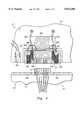
- FIG. 4illustrates another alternative embodiment of the computer docking system 8 of FIG. 1A, designated by a reference numeral 8".
- a PC 10the internal configuration of which may also be represented by the block diagram shown in FIG. 1B, is connectable to a slice 11" via mating electrical connectors 12", 13", respectively disposed on a housing 14" of the PC and a housing 15" of the slice.
- the PC 10"also includes two ferromagnetic plates 405, which are disposed proximate the connector 12".
- the slice 11"includes two retracting mechanisms, each of which comprise a spring 401, an attachment lanyard 502, a stop 506, and an end cap 508, and a ribbon cable 403, which attaches the connector 13" to peripheral device interconnect lines (not shown).
- the retracting mechanismsretractably attach the connector 13" to the slice body 15".
- the slice 11"further includes two electromagnets 209, which are physically and electrically connected to the connector 13" via a conducting wire 404.
- each of the plates 405is located close to one of the electromagnets 209, which are electrically connectable to a controller (not shown) of the PC 10" through the conductive wire 404, the connector 12 and the connector 13 for controlling the electrical energization of the electromagnets 209.
- electromagnets 209When electromagnets 209 are mechanically engaged and electrically energized, they attract the plates 405 with enough force that the connector 12" cannot be disconnected from the connector 13" by the application of ordinary force.
- the slice housing 15"may be separated a distance from the PC 10" equal to the slack in the lanyards 502 without disconnection of the connectors 12", 13".
- the springs 401begin to bias the connector 13" and the housing 15" to which it is attached back toward the PC 10".
- the connectors 12", 13"may be disconnected, thereby disconnecting the PC 10" from the slice 11", with the application of ordinary force.
- FIGS. 2A, and 2B, 3 and 4can be implemented in two different variations. These variations determine how and when the electromagnets 206, 207, 209 are electrically energized once the slice 11, 11', 11" and the PC 10, 10', 10" are in electrical engagement via connectors 12, 13, 12' 13', 12" 13".
- the electromagnets 206, 207, 209are electrically energized by the processor 30 whenever the PC 10, 10' 10" is docked to the slice 11, 11', 11" via connectors 12, 13, 12' 13', 12" 13" and power is applied to the docking system 8, 8', 8", such that the plates 205, 305, 405, are constantly attracted by the electromagnets 206, 207, 209.
- FIG. 4further depicts a second variation on each of the embodiments depicted in FIGS. 2A and 2B, 3, and 4.
- mechanical engagement and electrical energization of the electromagnets 206, 207, 209are separately controllable events.
- a proximity sensor or microswitch 501mounted to the slice housing 15, 15', 15" at the interface of the PC 10, 10', 10" and the slice 11, 11', 11", to detect separation of the two devices, at which point it sends a signal to electrically energize the electromagnets, thereby to prevent further separation of the devices.
- the microswitch 501serially connects between the electromagnets 209, and the processor 30, thereby creating an ⁇ AND ⁇ function.
- electromagnets 209electrically energize only when both the processor 30 and the microswitch 501 are electrically engaging them.
Landscapes
- Engineering & Computer Science (AREA)
- Theoretical Computer Science (AREA)
- Computer Hardware Design (AREA)
- Human Computer Interaction (AREA)
- Physics & Mathematics (AREA)
- General Engineering & Computer Science (AREA)
- General Physics & Mathematics (AREA)
- Details Of Connecting Devices For Male And Female Coupling (AREA)
Abstract
Description
Claims (35)
Priority Applications (1)
| Application Number | Priority Date | Filing Date | Title |
|---|---|---|---|
| US08/696,459US5812356A (en) | 1996-08-14 | 1996-08-14 | Computer docking system having an electromagnetic lock |
Applications Claiming Priority (1)
| Application Number | Priority Date | Filing Date | Title |
|---|---|---|---|
| US08/696,459US5812356A (en) | 1996-08-14 | 1996-08-14 | Computer docking system having an electromagnetic lock |
Publications (1)
| Publication Number | Publication Date |
|---|---|
| US5812356Atrue US5812356A (en) | 1998-09-22 |
Family
ID=24797162
Family Applications (1)
| Application Number | Title | Priority Date | Filing Date |
|---|---|---|---|
| US08/696,459Expired - LifetimeUS5812356A (en) | 1996-08-14 | 1996-08-14 | Computer docking system having an electromagnetic lock |
Country Status (1)
| Country | Link |
|---|---|
| US (1) | US5812356A (en) |
Cited By (72)
| Publication number | Priority date | Publication date | Assignee | Title |
|---|---|---|---|---|
| US6061234A (en)* | 1999-03-15 | 2000-05-09 | Dell U.S.A., L.P. | Secured snap-on cover for a computer system docking station |
| US6151218A (en)* | 1998-08-21 | 2000-11-21 | Compaq Computer Corporation | Physical security system for portable computer/port replicator |
| US6188572B1 (en)* | 1998-10-13 | 2001-02-13 | Dell Usa, L.P. | Movable docking station electrical connector |
| US6297963B1 (en)* | 1999-09-13 | 2001-10-02 | Hewlett-Packard Company | Security docking cable for computer docking system |
| US6418013B1 (en) | 1999-12-06 | 2002-07-09 | Dell Products Inc. | System and method for one touch operation of a docking station |
| SG90078A1 (en)* | 1999-11-15 | 2002-07-23 | Creative Tech Ltd | Docking interface for portable device |
| US20020103007A1 (en)* | 2001-01-26 | 2002-08-01 | Jaggers Christopher M. | Portable cell phone docking system |
| US6433445B1 (en)* | 2000-01-06 | 2002-08-13 | International Business Machines Corporation | Active mating connector |
| US20030046553A1 (en)* | 2001-08-29 | 2003-03-06 | Angelo Michael F. | Use of biometrics to provide physical and logic access to computer devices |
| US20030137905A1 (en)* | 2002-01-23 | 2003-07-24 | International Business Machines Corporation | Apparatus and method to transport a data storage medium disposed in a portable carrier |
| US20040209489A1 (en)* | 2003-04-21 | 2004-10-21 | Clapper Edward O. | Apparatus for automatic docking |
| US7076270B2 (en) | 2001-02-28 | 2006-07-11 | Dell Products L.P. | Docking station for wireless communication device |
| US20070072443A1 (en)* | 2005-09-26 | 2007-03-29 | Apple Computer, Inc. | Magnetic connector for electronic device |
| WO2007037807A1 (en)* | 2005-09-26 | 2007-04-05 | Apple Inc. | Electromagnetic connector for electronic device |
| US7298611B1 (en) | 2006-06-30 | 2007-11-20 | Carnevali Jeffrey D | Portable device docking station |
| EP1961367A1 (en)* | 2007-02-22 | 2008-08-27 | invendo medical GmbH | Electric plug device with integrated hydraulic/pneumatic connections |
| US20080209965A1 (en)* | 2005-07-21 | 2008-09-04 | Koninklijke Philips Electronics, N.V. | Software-Controlled Mechanical Lock for Portable Electronic Devices |
| US20080232061A1 (en)* | 2007-03-21 | 2008-09-25 | Asustek Computer Inc. | Portable Electronic System |
| US20090174990A1 (en)* | 2008-01-04 | 2009-07-09 | Apple Inc. | System For Coupling Interfacing Parts |
| US20090257203A1 (en)* | 2008-04-14 | 2009-10-15 | Sea-Weng Young | Mobile communication device with replaceable functional modules |
| WO2009109338A3 (en)* | 2008-03-07 | 2009-11-05 | Magcode Ag | Charging system for charging batteries that are disposed in electronic devices |
| CN101809826A (en)* | 2007-01-06 | 2010-08-18 | 苹果公司 | Headset connector for selectively routing signals according to determined orientation of mating connector |
| CN101950193A (en)* | 2010-09-27 | 2011-01-19 | 深圳市研祥通讯终端技术有限公司 | Dock and method for locking mobile terminal in same |
| US20110092081A1 (en)* | 2009-10-20 | 2011-04-21 | Apple Inc. | Magnetic connector having a unitary housing |
| US20110171837A1 (en)* | 2010-01-11 | 2011-07-14 | AUTOMOTIVE INDUSTRIAL MARKETING CORP., dba AIMCO | Magnetic cable connector systems |
| US20120021619A1 (en)* | 2010-07-21 | 2012-01-26 | Apple Inc. | Programmable magnetic connectors |
| US8179672B2 (en) | 2006-06-30 | 2012-05-15 | National Products, Inc. | Portable device docking station |
| CN102544896A (en)* | 2010-12-20 | 2012-07-04 | 联想(北京)有限公司 | Connector |
| US20120173770A1 (en)* | 2010-12-31 | 2012-07-05 | Research In Motion Limited | System and method for detecting accidental peripheral device disconnection |
| WO2012161399A1 (en)* | 2011-05-20 | 2012-11-29 | Smart Power Solutions, Inc. | Magnetic connecting device |
| US8351178B2 (en) | 2010-09-15 | 2013-01-08 | Transcend Information, Inc. | Electronic system with secured data accessing |
| US20130102164A1 (en)* | 2011-10-21 | 2013-04-25 | Acer Incorporated | Male connector and female connector in computer system |
| WO2013075847A1 (en)* | 2011-11-22 | 2013-05-30 | Sony Ericsson Mobile Communications Ab | An electrical device and a method therein |
| US20130143419A1 (en)* | 2011-12-01 | 2013-06-06 | Htc Corporation | Electronic apparatus assembly |
| WO2014021847A1 (en)* | 2012-07-31 | 2014-02-06 | Hewlett-Packard Development Company, L.P. | Magnetic connector for a computing device |
| US20140085800A1 (en)* | 2012-09-24 | 2014-03-27 | International Business Machines Corporation | Slim profile, rear docking tape drive canister |
| US8702316B2 (en) | 2008-09-30 | 2014-04-22 | Apple Inc. | Magnetic connector with optical signal path |
| US20140189891A1 (en)* | 2012-12-27 | 2014-07-03 | Hon Hai Precision Industry Co., Ltd. | Hard disk assembly and electronic device using same |
| US20140211409A1 (en)* | 2013-01-31 | 2014-07-31 | Hewlett- Packard Development Company, Lp | Post and Opening with Magnetic Elements to Facilitate Alignment |
| US20140266725A1 (en)* | 2013-03-15 | 2014-09-18 | Invue Security Products Inc. | Kiosk security for portable electronic device |
| US8888500B2 (en) | 2011-06-30 | 2014-11-18 | Apple Inc. | Robust magnetic connector |
| EP2764588A4 (en)* | 2011-10-04 | 2015-05-13 | Doobrow Todd | Quick-disconnect power adapters |
| US20150138720A1 (en)* | 2013-11-21 | 2015-05-21 | Toshiba Global Commerce Solutions Holdings Corporation | Computing device docking systems |
| US9065205B2 (en) | 2011-08-11 | 2015-06-23 | Apple Inc. | Connector insert having a cable crimp portion with protrusions and a receptacle having label in the front |
| US9083110B2 (en) | 2011-10-04 | 2015-07-14 | Todd Doobrow | Quick-disconnect power adapters |
| EP2901241A1 (en)* | 2012-09-26 | 2015-08-05 | Thinpad Technology (Shenzhen) Co Ltd. | Mobile-computer support apparatus |
| US20150234771A1 (en)* | 2014-02-20 | 2015-08-20 | Acer Incorporated | Docking station of portable electronic device and safe removing method thereof |
| US20150277491A1 (en)* | 2014-03-28 | 2015-10-01 | David W. Browning | Magnetic attachment mechanism for an electronic device |
| WO2014149248A3 (en)* | 2013-03-15 | 2015-10-29 | Invue Security Products Inc. | Kiosk security for portable electronic device |
| US9211161B2 (en) | 2013-03-06 | 2015-12-15 | DePuy Synthes Products, Inc. | Apparatus and methods for associating medical probes with connection ports |
| US20160087666A1 (en)* | 2014-09-24 | 2016-03-24 | Fu Tai Hua Industry (Shenzhen) Co., Ltd. | Electronic device |
| WO2016059201A1 (en)* | 2014-10-17 | 2016-04-21 | Ingenico Group | Mobile payment terminal comprising an on-board unlocking function |
| DE202015002228U1 (en)* | 2015-03-23 | 2016-06-27 | Faun Umwelttechnik Gmbh & Co. Kg | Lockable counterpart socket system |
| US9396861B2 (en)* | 2014-10-01 | 2016-07-19 | Wistron Corporation | Engaging module |
| US20160246329A1 (en)* | 2013-11-01 | 2016-08-25 | Hewlett-Packard Development Company, L.P. | Integrated power-security cable device |
| WO2016203302A1 (en)* | 2015-06-15 | 2016-12-22 | Sony Mobile Communications Inc. | Controlling of a magnetic connection between an electrical device and a cable |
| CN106463884A (en)* | 2014-05-07 | 2017-02-22 | 微软技术许可有限责任公司 | Electronic tapered connector |
| US9727083B2 (en)* | 2015-10-19 | 2017-08-08 | Hand Held Products, Inc. | Quick release dock system and method |
| US9728915B2 (en) | 2015-05-19 | 2017-08-08 | Microsoft Technology Licensing, Llc | Tapered-fang electronic connector |
| US9791634B2 (en) | 2008-09-30 | 2017-10-17 | Apple Inc. | Magnetic connector with optical signal path |
| US9854343B2 (en) | 2005-09-26 | 2017-12-26 | Apple Inc. | Headset connector |
| US9991628B2 (en) | 2014-07-21 | 2018-06-05 | Daniel J Daoura | Quick connect magnetic interface products and methods |
| US10004141B2 (en)* | 2013-03-21 | 2018-06-19 | Vorwerk & Co. Interholding Gmbh | Kitchen appliance operable by electric motor, data memory element, and combination of a kitchen appliance operable by electric motor and a data memory element |
| US10074469B2 (en) | 2016-06-06 | 2018-09-11 | Apple Inc. | Magnetic materials polarized at an oblique angle |
| US10096938B2 (en) | 2011-10-04 | 2018-10-09 | Todd Doobrow | Quick-disconnect power adapters |
| US10511127B2 (en) | 2018-03-20 | 2019-12-17 | Microsoft Technology Licensing, Llc | High-speed electronic connector |
| US20190383073A1 (en)* | 2016-12-19 | 2019-12-19 | Huawei Technologies Co., Ltd. | Notebook Computer |
| US10579096B1 (en)* | 2018-09-20 | 2020-03-03 | Apple Inc. | Contact design for external accessories |
| US10582284B2 (en) | 2015-09-30 | 2020-03-03 | Apple Inc. | In-ear headphone |
| US10718996B2 (en) | 2018-12-19 | 2020-07-21 | Arlo Technologies, Inc. | Modular camera system |
| US11424573B2 (en) | 2020-09-24 | 2022-08-23 | Apple Inc. | Magnetic connectors with self-centering floating contacts |
| US20240419219A1 (en)* | 2023-06-15 | 2024-12-19 | Microsoft Technology Licensing, Llc | Secure electromagnetic docking system |
Citations (8)
| Publication number | Priority date | Publication date | Assignee | Title |
|---|---|---|---|---|
| US4546267A (en)* | 1984-01-11 | 1985-10-08 | Steven Urfirer | Modular equipment connection |
| US4718858A (en)* | 1986-06-16 | 1988-01-12 | Western Digital Corporation | Mechanical interconnect system for electronic units enclosed in stackable housings |
| US4720128A (en)* | 1985-02-12 | 1988-01-19 | Reliable Security Systems, Inc. | Magnetic emergency exit door lock with time delay |
| US5313596A (en)* | 1993-01-05 | 1994-05-17 | Dell Usa Lp | Motorized portable computer/expansion chassis docking system |
| US5396400A (en)* | 1993-05-20 | 1995-03-07 | Dell Usa, L.P. | Convertible computer apparatus acting as a desk-top computer or a docking station |
| US5402320A (en)* | 1993-11-18 | 1995-03-28 | Northern Telecom Limited | Electronic shelf keying and alignment combination |
| US5452180A (en)* | 1993-07-15 | 1995-09-19 | Dell Usa, L.P. | Docking apparatus for a portable data processing unit including an arcuate support member with a card extension pivotally mounted on a base member |
| US5526493A (en)* | 1993-06-03 | 1996-06-11 | Dell Usa | Docking detection and suspend circuit for portable computer/expansion chassis docking system |
- 1996
- 1996-08-14USUS08/696,459patent/US5812356A/ennot_activeExpired - Lifetime
Patent Citations (8)
| Publication number | Priority date | Publication date | Assignee | Title |
|---|---|---|---|---|
| US4546267A (en)* | 1984-01-11 | 1985-10-08 | Steven Urfirer | Modular equipment connection |
| US4720128A (en)* | 1985-02-12 | 1988-01-19 | Reliable Security Systems, Inc. | Magnetic emergency exit door lock with time delay |
| US4718858A (en)* | 1986-06-16 | 1988-01-12 | Western Digital Corporation | Mechanical interconnect system for electronic units enclosed in stackable housings |
| US5313596A (en)* | 1993-01-05 | 1994-05-17 | Dell Usa Lp | Motorized portable computer/expansion chassis docking system |
| US5396400A (en)* | 1993-05-20 | 1995-03-07 | Dell Usa, L.P. | Convertible computer apparatus acting as a desk-top computer or a docking station |
| US5526493A (en)* | 1993-06-03 | 1996-06-11 | Dell Usa | Docking detection and suspend circuit for portable computer/expansion chassis docking system |
| US5452180A (en)* | 1993-07-15 | 1995-09-19 | Dell Usa, L.P. | Docking apparatus for a portable data processing unit including an arcuate support member with a card extension pivotally mounted on a base member |
| US5402320A (en)* | 1993-11-18 | 1995-03-28 | Northern Telecom Limited | Electronic shelf keying and alignment combination |
Cited By (173)
| Publication number | Priority date | Publication date | Assignee | Title |
|---|---|---|---|---|
| US6151218A (en)* | 1998-08-21 | 2000-11-21 | Compaq Computer Corporation | Physical security system for portable computer/port replicator |
| US6188572B1 (en)* | 1998-10-13 | 2001-02-13 | Dell Usa, L.P. | Movable docking station electrical connector |
| US6061234A (en)* | 1999-03-15 | 2000-05-09 | Dell U.S.A., L.P. | Secured snap-on cover for a computer system docking station |
| US6297963B1 (en)* | 1999-09-13 | 2001-10-02 | Hewlett-Packard Company | Security docking cable for computer docking system |
| SG90078A1 (en)* | 1999-11-15 | 2002-07-23 | Creative Tech Ltd | Docking interface for portable device |
| US6418013B1 (en) | 1999-12-06 | 2002-07-09 | Dell Products Inc. | System and method for one touch operation of a docking station |
| US6433445B1 (en)* | 2000-01-06 | 2002-08-13 | International Business Machines Corporation | Active mating connector |
| US20020103007A1 (en)* | 2001-01-26 | 2002-08-01 | Jaggers Christopher M. | Portable cell phone docking system |
| US7013163B2 (en) | 2001-01-26 | 2006-03-14 | Dell Products L.P. | Portable wireless communication device docking system |
| US7076270B2 (en) | 2001-02-28 | 2006-07-11 | Dell Products L.P. | Docking station for wireless communication device |
| US20030046553A1 (en)* | 2001-08-29 | 2003-03-06 | Angelo Michael F. | Use of biometrics to provide physical and logic access to computer devices |
| US7167987B2 (en)* | 2001-08-29 | 2007-01-23 | Hewlett-Packard Development Company, L.P. | Use of biometrics to provide physical and logic access to computer devices |
| US6954938B2 (en) | 2002-01-23 | 2005-10-11 | International Business Machines Corporation | Apparatus and method to transport a data storage medium disposed in a portable carrier |
| US20030137905A1 (en)* | 2002-01-23 | 2003-07-24 | International Business Machines Corporation | Apparatus and method to transport a data storage medium disposed in a portable carrier |
| US20040209489A1 (en)* | 2003-04-21 | 2004-10-21 | Clapper Edward O. | Apparatus for automatic docking |
| US20080209965A1 (en)* | 2005-07-21 | 2008-09-04 | Koninklijke Philips Electronics, N.V. | Software-Controlled Mechanical Lock for Portable Electronic Devices |
| US10490933B2 (en) | 2005-09-26 | 2019-11-26 | Apple Inc. | Magnetic connector for electronic device |
| US8690582B2 (en) | 2005-09-26 | 2014-04-08 | Apple Inc. | Magnetic connector for electronic device |
| US7311526B2 (en) | 2005-09-26 | 2007-12-25 | Apple Inc. | Magnetic connector for electronic device |
| US9711893B2 (en) | 2005-09-26 | 2017-07-18 | Apple Inc. | Magnetic connector for electronic device |
| EP2290754B1 (en) | 2005-09-26 | 2016-09-21 | Apple Inc. | Electromagnetic connector for electronic device |
| US9854343B2 (en) | 2005-09-26 | 2017-12-26 | Apple Inc. | Headset connector |
| US10090618B2 (en) | 2005-09-26 | 2018-10-02 | Apple Inc. | Magnetic connector for electronic device |
| CN102664331B (en)* | 2005-09-26 | 2016-03-02 | 苹果公司 | Magnetic connector system |
| US7351066B2 (en) | 2005-09-26 | 2008-04-01 | Apple Computer, Inc. | Electromagnetic connector for electronic device |
| GB2444689A (en)* | 2005-09-26 | 2008-06-11 | Apple Inc | Electromagnetic connector for electronic device |
| WO2007037807A1 (en)* | 2005-09-26 | 2007-04-05 | Apple Inc. | Electromagnetic connector for electronic device |
| US9112304B2 (en) | 2005-09-26 | 2015-08-18 | Apple Inc. | Magnetic connector for electronic device |
| CN102664321B (en)* | 2005-09-26 | 2015-06-10 | 苹果公司 | Connector plug, connector receptacle and method for forming multiple electric paths |
| US20070072443A1 (en)* | 2005-09-26 | 2007-03-29 | Apple Computer, Inc. | Magnetic connector for electronic device |
| US8970332B2 (en) | 2005-09-26 | 2015-03-03 | Apple Inc. | Electromagnetic connector for electronic device |
| US20080280461A1 (en)* | 2005-09-26 | 2008-11-13 | Apple Inc. | Electromagnetic connector for electronic device |
| GB2444689B (en)* | 2005-09-26 | 2011-06-15 | Apple Inc | Magnetic connector for electronic device |
| US11233356B2 (en) | 2005-09-26 | 2022-01-25 | Apple Inc. | Magnetic connector for electronic device |
| US20090181556A1 (en)* | 2005-09-26 | 2009-07-16 | Apple Inc. | Magnetic connector for electronic device |
| US9634428B2 (en) | 2005-09-26 | 2017-04-25 | Apple Inc. | Electromagnetic connector for electronic device |
| US8497753B2 (en) | 2005-09-26 | 2013-07-30 | Apple Inc. | Electromagnetic connector for electronic device |
| US8435042B2 (en) | 2005-09-26 | 2013-05-07 | Apple Inc. | Magnetic connector for electronic device |
| CN102664331A (en)* | 2005-09-26 | 2012-09-12 | 苹果公司 | Magnetic connector system |
| US7641477B2 (en) | 2005-09-26 | 2010-01-05 | Apple Inc. | Electromagnetic connector for electronic device |
| US7645143B2 (en) | 2005-09-26 | 2010-01-12 | Apple Inc. | Magnetic connector for electronic device |
| US20100035441A1 (en)* | 2005-09-26 | 2010-02-11 | Apple Inc. | Magnetic connector for electronic device |
| CN102664321A (en)* | 2005-09-26 | 2012-09-12 | 苹果公司 | Connector plug, connector receptacle and method for forming multiple electric paths |
| CN101273499B (en)* | 2005-09-26 | 2012-05-30 | 苹果公司 | Electromagnetic connector for electronic device |
| US8177560B2 (en) | 2005-09-26 | 2012-05-15 | Apple Inc. | Magnetic connector for electronic device |
| US8087939B2 (en) | 2005-09-26 | 2012-01-03 | Apple Inc. | Magnetic connector for electronic device |
| EP2290754A1 (en)* | 2005-09-26 | 2011-03-02 | Apple Inc. | Electromagnetic connector for electronic device |
| US7901216B2 (en) | 2005-09-26 | 2011-03-08 | Apple Inc. | Magnetic connector for electronic device |
| EP2287972A3 (en)* | 2005-09-26 | 2011-04-20 | Apple Inc. | Electromagnetic connector for electronic device |
| EP2387114A1 (en)* | 2005-09-26 | 2011-11-16 | Apple Inc. | Electromagnetic connector for electronic device |
| EP2290755A3 (en)* | 2005-09-26 | 2011-04-27 | Apple Inc. | Electromagnetic connector for electronic device |
| EP2290756A3 (en)* | 2005-09-26 | 2011-04-27 | Apple Inc. | Electromagnetic connector for electronic device |
| US20110136351A1 (en)* | 2005-09-26 | 2011-06-09 | Apple Inc. | Magnetic connector for electronic device |
| US8179672B2 (en) | 2006-06-30 | 2012-05-15 | National Products, Inc. | Portable device docking station |
| US20080002345A1 (en)* | 2006-06-30 | 2008-01-03 | Carnevali Jeffrey D | Portable device docking station |
| US7573706B2 (en) | 2006-06-30 | 2009-08-11 | Carnevali Jeffrey D | Portable device docking station |
| US20080002369A1 (en)* | 2006-06-30 | 2008-01-03 | Carnevali Jeffrey D | Portable device docking station |
| US7298611B1 (en) | 2006-06-30 | 2007-11-20 | Carnevali Jeffrey D | Portable device docking station |
| US7315453B1 (en) | 2006-06-30 | 2008-01-01 | Carnevali Jeffrey D | Portable device docking station |
| US7508661B2 (en) | 2006-06-30 | 2009-03-24 | Carnevali Jeffrey D | Portable device docking station |
| US9036343B2 (en) | 2006-06-30 | 2015-05-19 | National Products, Inc. | Portable device docking station |
| US20080002351A1 (en)* | 2006-06-30 | 2008-01-03 | Carnevali Jeffrey D | Portable device docking station |
| US7417855B2 (en) | 2006-06-30 | 2008-08-26 | Carnevali Jeffrey D | Portable device docking station |
| US20080002353A1 (en)* | 2006-06-30 | 2008-01-03 | Carnevali Jeffrey D | Portable device docking station |
| CN104202689B (en)* | 2007-01-06 | 2018-07-20 | 苹果公司 | According to the headset connector of the set direction route signal of determining engaging connector |
| CN101809826A (en)* | 2007-01-06 | 2010-08-18 | 苹果公司 | Headset connector for selectively routing signals according to determined orientation of mating connector |
| US10979796B2 (en) | 2007-01-06 | 2021-04-13 | Apple Inc. | In-ear wireless listening device |
| US11336985B2 (en) | 2007-01-06 | 2022-05-17 | Apple Inc. | In-ear wireless device |
| US10771880B1 (en) | 2007-01-06 | 2020-09-08 | Apple Inc. | In-ear wireless device |
| US20180255389A1 (en) | 2007-01-06 | 2018-09-06 | Apple Inc. | Headset connector |
| US10516931B2 (en) | 2007-01-06 | 2019-12-24 | Apple Inc. | Headset connector |
| US10165346B2 (en) | 2007-01-06 | 2018-12-25 | Apple Inc. | Headset connector |
| US10993011B2 (en) | 2007-01-06 | 2021-04-27 | Apple Inc. | In-ear wireless listening device |
| US9967646B2 (en) | 2007-01-06 | 2018-05-08 | Apple Inc. | Headset connector |
| US12231837B2 (en) | 2007-01-06 | 2025-02-18 | Apple Inc. | In-ear wireless device |
| US10433043B2 (en) | 2007-01-06 | 2019-10-01 | Apple Inc. | In-ear listening device |
| US10959006B2 (en) | 2007-01-06 | 2021-03-23 | Apple Inc. | In-ear wireless listening device |
| US11877112B2 (en) | 2007-01-06 | 2024-01-16 | Apple Inc. | In-ear wireless device |
| US10313775B2 (en) | 2007-01-06 | 2019-06-04 | Apple Inc. | Portable listening device system |
| EP1961367A1 (en)* | 2007-02-22 | 2008-08-27 | invendo medical GmbH | Electric plug device with integrated hydraulic/pneumatic connections |
| US20080207028A1 (en)* | 2007-02-22 | 2008-08-28 | Invendo Medical Gmbh | Electric plug device including integrated hydraulic/pneumatic ports |
| US7621766B2 (en) | 2007-02-22 | 2009-11-24 | Invendo Medical Gmbh | Electric plug device including integrated hydraulic/pneumatic ports |
| US20080232061A1 (en)* | 2007-03-21 | 2008-09-25 | Asustek Computer Inc. | Portable Electronic System |
| US20090174990A1 (en)* | 2008-01-04 | 2009-07-09 | Apple Inc. | System For Coupling Interfacing Parts |
| US7762817B2 (en) | 2008-01-04 | 2010-07-27 | Apple Inc. | System for coupling interfacing parts |
| US7997906B2 (en) | 2008-01-04 | 2011-08-16 | Apple Inc. | Techniques for coupling interfaces parts using moveable magnetic elements |
| US20100254111A1 (en)* | 2008-01-04 | 2010-10-07 | Apple Inc. | System for coupling interfacing parts |
| WO2009109338A3 (en)* | 2008-03-07 | 2009-11-05 | Magcode Ag | Charging system for charging batteries that are disposed in electronic devices |
| DE102008013214B4 (en) | 2008-03-07 | 2025-02-06 | Rosenberger Hochfrequenztechnik Gmbh & Co. Kg | charging system |
| US20090257203A1 (en)* | 2008-04-14 | 2009-10-15 | Sea-Weng Young | Mobile communication device with replaceable functional modules |
| US8770857B2 (en) | 2008-09-30 | 2014-07-08 | Apple Inc. | Magnetic connector with optical signal path |
| US9791634B2 (en) | 2008-09-30 | 2017-10-17 | Apple Inc. | Magnetic connector with optical signal path |
| US8702316B2 (en) | 2008-09-30 | 2014-04-22 | Apple Inc. | Magnetic connector with optical signal path |
| US9281612B2 (en) | 2009-10-20 | 2016-03-08 | Apple Inc. | Magnetic connector having a unitary housing |
| US8535088B2 (en) | 2009-10-20 | 2013-09-17 | Apple Inc. | Magnetic connector having a unitary housing |
| US9923301B2 (en) | 2009-10-20 | 2018-03-20 | Apple Inc. | Magnetic connector having a unitary housing |
| US20110092081A1 (en)* | 2009-10-20 | 2011-04-21 | Apple Inc. | Magnetic connector having a unitary housing |
| US8348678B2 (en) | 2010-01-11 | 2013-01-08 | Automotive Industrial Marketing Corp. | Magnetic cable connector systems |
| US20110171837A1 (en)* | 2010-01-11 | 2011-07-14 | AUTOMOTIVE INDUSTRIAL MARKETING CORP., dba AIMCO | Magnetic cable connector systems |
| US20120021619A1 (en)* | 2010-07-21 | 2012-01-26 | Apple Inc. | Programmable magnetic connectors |
| US9590352B2 (en) | 2010-07-21 | 2017-03-07 | Apple Inc. | Magnetically-implemented security devices |
| US8963666B2 (en)* | 2010-07-21 | 2015-02-24 | Apple Inc. | Programmable magnetic connectors |
| US8576034B2 (en)* | 2010-07-21 | 2013-11-05 | Apple Inc. | Alignment and connection for devices |
| US20120028480A1 (en)* | 2010-07-21 | 2012-02-02 | Apple Inc. | Alignment and connection for devices |
| US8351178B2 (en) | 2010-09-15 | 2013-01-08 | Transcend Information, Inc. | Electronic system with secured data accessing |
| CN101950193B (en)* | 2010-09-27 | 2012-08-22 | 深圳市研祥通讯终端技术有限公司 | Dock and method for locking mobile terminal in same |
| CN101950193A (en)* | 2010-09-27 | 2011-01-19 | 深圳市研祥通讯终端技术有限公司 | Dock and method for locking mobile terminal in same |
| CN102544896B (en)* | 2010-12-20 | 2014-12-31 | 联想(北京)有限公司 | Connector |
| CN102544896A (en)* | 2010-12-20 | 2012-07-04 | 联想(北京)有限公司 | Connector |
| US9052758B2 (en)* | 2010-12-31 | 2015-06-09 | Blackberry Limited | System and method for detecting accidental peripheral device disconnection |
| US20120173770A1 (en)* | 2010-12-31 | 2012-07-05 | Research In Motion Limited | System and method for detecting accidental peripheral device disconnection |
| WO2012161399A1 (en)* | 2011-05-20 | 2012-11-29 | Smart Power Solutions, Inc. | Magnetic connecting device |
| US8888500B2 (en) | 2011-06-30 | 2014-11-18 | Apple Inc. | Robust magnetic connector |
| US9923290B2 (en) | 2011-06-30 | 2018-03-20 | Apple Inc. | Robust magnetic connector |
| US9461403B2 (en) | 2011-06-30 | 2016-10-04 | Apple Inc. | Robust magnetic connector |
| US9660376B2 (en) | 2011-08-11 | 2017-05-23 | Apple Inc. | Connector insert having a cable crimp portion with protrusions and a receptacle having a label in the front |
| US9065205B2 (en) | 2011-08-11 | 2015-06-23 | Apple Inc. | Connector insert having a cable crimp portion with protrusions and a receptacle having label in the front |
| US10096938B2 (en) | 2011-10-04 | 2018-10-09 | Todd Doobrow | Quick-disconnect power adapters |
| US9083110B2 (en) | 2011-10-04 | 2015-07-14 | Todd Doobrow | Quick-disconnect power adapters |
| EP2764588A4 (en)* | 2011-10-04 | 2015-05-13 | Doobrow Todd | Quick-disconnect power adapters |
| US20130102164A1 (en)* | 2011-10-21 | 2013-04-25 | Acer Incorporated | Male connector and female connector in computer system |
| WO2013075847A1 (en)* | 2011-11-22 | 2013-05-30 | Sony Ericsson Mobile Communications Ab | An electrical device and a method therein |
| US8920178B2 (en)* | 2011-12-01 | 2014-12-30 | Htc Corporation | Electronic apparatus assembly |
| US20130143419A1 (en)* | 2011-12-01 | 2013-06-06 | Htc Corporation | Electronic apparatus assembly |
| WO2014021847A1 (en)* | 2012-07-31 | 2014-02-06 | Hewlett-Packard Development Company, L.P. | Magnetic connector for a computing device |
| US9735500B2 (en) | 2012-07-31 | 2017-08-15 | Hewlett-Packard Development Company, L.P. | Magnetic connector for a computing device |
| US9330729B2 (en)* | 2012-09-24 | 2016-05-03 | International Business Machines Corporation | Slim profile, rear docking tape drive canister |
| US20140085800A1 (en)* | 2012-09-24 | 2014-03-27 | International Business Machines Corporation | Slim profile, rear docking tape drive canister |
| US9390763B2 (en) | 2012-09-24 | 2016-07-12 | International Business Machines Corporation | Slim profile, rear docking tape drive canister |
| EP2901241A1 (en)* | 2012-09-26 | 2015-08-05 | Thinpad Technology (Shenzhen) Co Ltd. | Mobile-computer support apparatus |
| US20140189891A1 (en)* | 2012-12-27 | 2014-07-03 | Hon Hai Precision Industry Co., Ltd. | Hard disk assembly and electronic device using same |
| US9007761B2 (en)* | 2013-01-31 | 2015-04-14 | Hewlett-Packard Development Company, L.P. | Post and opening with magnetic elements to facilitate alignment |
| US20140211409A1 (en)* | 2013-01-31 | 2014-07-31 | Hewlett- Packard Development Company, Lp | Post and Opening with Magnetic Elements to Facilitate Alignment |
| US9211161B2 (en) | 2013-03-06 | 2015-12-15 | DePuy Synthes Products, Inc. | Apparatus and methods for associating medical probes with connection ports |
| US20140266725A1 (en)* | 2013-03-15 | 2014-09-18 | Invue Security Products Inc. | Kiosk security for portable electronic device |
| WO2014149248A3 (en)* | 2013-03-15 | 2015-10-29 | Invue Security Products Inc. | Kiosk security for portable electronic device |
| US10004141B2 (en)* | 2013-03-21 | 2018-06-19 | Vorwerk & Co. Interholding Gmbh | Kitchen appliance operable by electric motor, data memory element, and combination of a kitchen appliance operable by electric motor and a data memory element |
| US20160246329A1 (en)* | 2013-11-01 | 2016-08-25 | Hewlett-Packard Development Company, L.P. | Integrated power-security cable device |
| US9766657B2 (en)* | 2013-11-01 | 2017-09-19 | Hewlett-Packard Development Company, L.P. | Integrated power-security cable device |
| US20150138720A1 (en)* | 2013-11-21 | 2015-05-21 | Toshiba Global Commerce Solutions Holdings Corporation | Computing device docking systems |
| US9429993B2 (en)* | 2013-11-21 | 2016-08-30 | Toshiba Global Commerce Solutions Holdings Corporation | Computing device docking systems |
| US20150234771A1 (en)* | 2014-02-20 | 2015-08-20 | Acer Incorporated | Docking station of portable electronic device and safe removing method thereof |
| US9665125B2 (en)* | 2014-03-28 | 2017-05-30 | Intel Corporation | Magnetic attachment mechanism for an electronic device |
| US20150277491A1 (en)* | 2014-03-28 | 2015-10-01 | David W. Browning | Magnetic attachment mechanism for an electronic device |
| CN106463884A (en)* | 2014-05-07 | 2017-02-22 | 微软技术许可有限责任公司 | Electronic tapered connector |
| US9843137B2 (en) | 2014-05-07 | 2017-12-12 | Microsoft Technology Licensing, Llc | Electronic connector |
| AU2015256407B2 (en)* | 2014-05-07 | 2018-12-13 | Microsoft Technology Licensing, Llc | Electronic tapered connector |
| US9991628B2 (en) | 2014-07-21 | 2018-06-05 | Daniel J Daoura | Quick connect magnetic interface products and methods |
| US20160087666A1 (en)* | 2014-09-24 | 2016-03-24 | Fu Tai Hua Industry (Shenzhen) Co., Ltd. | Electronic device |
| US9396861B2 (en)* | 2014-10-01 | 2016-07-19 | Wistron Corporation | Engaging module |
| WO2016059201A1 (en)* | 2014-10-17 | 2016-04-21 | Ingenico Group | Mobile payment terminal comprising an on-board unlocking function |
| US20170236109A1 (en)* | 2014-10-17 | 2017-08-17 | Ingenico Group | Mobile payment terminal comprising an embedded unlocking function |
| US10943221B2 (en)* | 2014-10-17 | 2021-03-09 | Ingenico Group | Mobile payment terminal comprising an embedded unlocking function |
| FR3027330A1 (en)* | 2014-10-17 | 2016-04-22 | Compagnie Ind Et Financiere Dingenierie Ingenico | MOBILE PAYMENT TERMINAL COMPRISING AN EMBARKETED UNLOCKING FUNCTION |
| DE202015002228U1 (en)* | 2015-03-23 | 2016-06-27 | Faun Umwelttechnik Gmbh & Co. Kg | Lockable counterpart socket system |
| US9728915B2 (en) | 2015-05-19 | 2017-08-08 | Microsoft Technology Licensing, Llc | Tapered-fang electronic connector |
| US9767949B2 (en) | 2015-06-15 | 2017-09-19 | Sony Corporation | Controlling of a magnetic connection between an electrical device and a cable |
| WO2016203302A1 (en)* | 2015-06-15 | 2016-12-22 | Sony Mobile Communications Inc. | Controlling of a magnetic connection between an electrical device and a cable |
| US10694276B2 (en) | 2015-09-30 | 2020-06-23 | Apple Inc. | In-ear headphone |
| US11930313B2 (en) | 2015-09-30 | 2024-03-12 | Apple Inc. | In-ear headphone |
| US12284475B2 (en) | 2015-09-30 | 2025-04-22 | Apple Inc. | In-ear headphone |
| US10582284B2 (en) | 2015-09-30 | 2020-03-03 | Apple Inc. | In-ear headphone |
| US10841683B2 (en) | 2015-09-30 | 2020-11-17 | Apple Inc. | In-ear headphone |
| US11265638B2 (en) | 2015-09-30 | 2022-03-01 | Apple Inc. | In-ear headphone |
| US9727083B2 (en)* | 2015-10-19 | 2017-08-08 | Hand Held Products, Inc. | Quick release dock system and method |
| US10074469B2 (en) | 2016-06-06 | 2018-09-11 | Apple Inc. | Magnetic materials polarized at an oblique angle |
| US11066861B2 (en)* | 2016-12-19 | 2021-07-20 | Huawei Technologies Co., Ltd. | Notebook computer |
| US20190383073A1 (en)* | 2016-12-19 | 2019-12-19 | Huawei Technologies Co., Ltd. | Notebook Computer |
| US10511127B2 (en) | 2018-03-20 | 2019-12-17 | Microsoft Technology Licensing, Llc | High-speed electronic connector |
| US10579096B1 (en)* | 2018-09-20 | 2020-03-03 | Apple Inc. | Contact design for external accessories |
| US10718996B2 (en) | 2018-12-19 | 2020-07-21 | Arlo Technologies, Inc. | Modular camera system |
| US11424573B2 (en) | 2020-09-24 | 2022-08-23 | Apple Inc. | Magnetic connectors with self-centering floating contacts |
| US20240419219A1 (en)* | 2023-06-15 | 2024-12-19 | Microsoft Technology Licensing, Llc | Secure electromagnetic docking system |
Similar Documents
| Publication | Publication Date | Title |
|---|---|---|
| US5812356A (en) | Computer docking system having an electromagnetic lock | |
| US7142421B2 (en) | Docking station for locking a notebook computer | |
| US6522532B2 (en) | Cable docking system and method for a computer | |
| US6231371B1 (en) | Docking station for multiple devices | |
| US6040981A (en) | Method and apparatus for a power supply cam with integrated cooling fan | |
| US8035961B2 (en) | Controlled compression of hard drive carrier CAM | |
| US6407914B1 (en) | Docking system for portable computer | |
| US5436857A (en) | Personal computer module system and method of using | |
| US6244889B1 (en) | Method and apparatus for an electromechanically controlled electronic interface plug | |
| US7381079B2 (en) | Locking link rod structure for a docking station | |
| US6061234A (en) | Secured snap-on cover for a computer system docking station | |
| US8821173B2 (en) | Docking station having preload and connector isolator system | |
| US5051868A (en) | Computer construction | |
| US6669497B2 (en) | Self-locking mechanism for a hot pluggable printed circuit board | |
| US20030156383A1 (en) | Core computer system | |
| WO1996007002A1 (en) | Security device for a portable computer | |
| US20030209361A1 (en) | Cable retention apparatus | |
| US6189349B1 (en) | Single retracting security hook of desktop port replicator providing security for dissimilar multiple portable computers | |
| US6769927B2 (en) | Card retention device | |
| US7379303B2 (en) | Computing device module | |
| WO2016018222A1 (en) | Connecting a peripheral device | |
| US7079385B1 (en) | Docking station lock and its link assembly | |
| US9651994B1 (en) | Docking station with anti-theft mechanism for portable electronic device | |
| Cisco | Replacing Parts | |
| Cisco | Replacing Parts |
Legal Events
| Date | Code | Title | Description |
|---|---|---|---|
| AS | Assignment | Owner name:DELL U.S.A. L.P., TEXAS Free format text:ASSIGNMENT OF ASSIGNORS INTEREST;ASSIGNOR:O'CONNOR, CLINT;REEL/FRAME:008149/0330 Effective date:19960809 | |
| STCF | Information on status: patent grant | Free format text:PATENTED CASE | |
| FEPP | Fee payment procedure | Free format text:PAYOR NUMBER ASSIGNED (ORIGINAL EVENT CODE: ASPN); ENTITY STATUS OF PATENT OWNER: LARGE ENTITY | |
| FPAY | Fee payment | Year of fee payment:4 | |
| REMI | Maintenance fee reminder mailed | ||
| FPAY | Fee payment | Year of fee payment:8 | |
| FPAY | Fee payment | Year of fee payment:12 | |
| AS | Assignment | Owner name:BANK OF AMERICA, N.A., AS ADMINISTRATIVE AGENT, TE Free format text:PATENT SECURITY AGREEMENT (ABL);ASSIGNORS:DELL INC.;APPASSURE SOFTWARE, INC.;ASAP SOFTWARE EXPRESS, INC.;AND OTHERS;REEL/FRAME:031898/0001 Effective date:20131029 Owner name:BANK OF AMERICA, N.A., AS ADMINISTRATIVE AGENT, TEXAS Free format text:PATENT SECURITY AGREEMENT (ABL);ASSIGNORS:DELL INC.;APPASSURE SOFTWARE, INC.;ASAP SOFTWARE EXPRESS, INC.;AND OTHERS;REEL/FRAME:031898/0001 Effective date:20131029 Owner name:BANK OF NEW YORK MELLON TRUST COMPANY, N.A., AS FIRST LIEN COLLATERAL AGENT, TEXAS Free format text:PATENT SECURITY AGREEMENT (NOTES);ASSIGNORS:APPASSURE SOFTWARE, INC.;ASAP SOFTWARE EXPRESS, INC.;BOOMI, INC.;AND OTHERS;REEL/FRAME:031897/0348 Effective date:20131029 Owner name:BANK OF AMERICA, N.A., AS COLLATERAL AGENT, NORTH CAROLINA Free format text:PATENT SECURITY AGREEMENT (TERM LOAN);ASSIGNORS:DELL INC.;APPASSURE SOFTWARE, INC.;ASAP SOFTWARE EXPRESS, INC.;AND OTHERS;REEL/FRAME:031899/0261 Effective date:20131029 Owner name:BANK OF AMERICA, N.A., AS COLLATERAL AGENT, NORTH Free format text:PATENT SECURITY AGREEMENT (TERM LOAN);ASSIGNORS:DELL INC.;APPASSURE SOFTWARE, INC.;ASAP SOFTWARE EXPRESS, INC.;AND OTHERS;REEL/FRAME:031899/0261 Effective date:20131029 Owner name:BANK OF NEW YORK MELLON TRUST COMPANY, N.A., AS FI Free format text:PATENT SECURITY AGREEMENT (NOTES);ASSIGNORS:APPASSURE SOFTWARE, INC.;ASAP SOFTWARE EXPRESS, INC.;BOOMI, INC.;AND OTHERS;REEL/FRAME:031897/0348 Effective date:20131029 | |
| AS | Assignment | Owner name:DELL SOFTWARE INC., CALIFORNIA Free format text:RELEASE BY SECURED PARTY;ASSIGNOR:BANK OF AMERICA, N.A., AS ADMINISTRATIVE AGENT;REEL/FRAME:040065/0216 Effective date:20160907 Owner name:DELL MARKETING L.P., TEXAS Free format text:RELEASE BY SECURED PARTY;ASSIGNOR:BANK OF AMERICA, N.A., AS ADMINISTRATIVE AGENT;REEL/FRAME:040065/0216 Effective date:20160907 Owner name:FORCE10 NETWORKS, INC., CALIFORNIA Free format text:RELEASE BY SECURED PARTY;ASSIGNOR:BANK OF AMERICA, N.A., AS ADMINISTRATIVE AGENT;REEL/FRAME:040065/0216 Effective date:20160907 Owner name:COMPELLANT TECHNOLOGIES, INC., MINNESOTA Free format text:RELEASE BY SECURED PARTY;ASSIGNOR:BANK OF AMERICA, N.A., AS ADMINISTRATIVE AGENT;REEL/FRAME:040065/0216 Effective date:20160907 Owner name:DELL INC., TEXAS Free format text:RELEASE BY SECURED PARTY;ASSIGNOR:BANK OF AMERICA, N.A., AS ADMINISTRATIVE AGENT;REEL/FRAME:040065/0216 Effective date:20160907 Owner name:APPASSURE SOFTWARE, INC., VIRGINIA Free format text:RELEASE BY SECURED PARTY;ASSIGNOR:BANK OF AMERICA, N.A., AS ADMINISTRATIVE AGENT;REEL/FRAME:040065/0216 Effective date:20160907 Owner name:PEROT SYSTEMS CORPORATION, TEXAS Free format text:RELEASE BY SECURED PARTY;ASSIGNOR:BANK OF AMERICA, N.A., AS ADMINISTRATIVE AGENT;REEL/FRAME:040065/0216 Effective date:20160907 Owner name:CREDANT TECHNOLOGIES, INC., TEXAS Free format text:RELEASE BY SECURED PARTY;ASSIGNOR:BANK OF AMERICA, N.A., AS ADMINISTRATIVE AGENT;REEL/FRAME:040065/0216 Effective date:20160907 Owner name:ASAP SOFTWARE EXPRESS, INC., ILLINOIS Free format text:RELEASE BY SECURED PARTY;ASSIGNOR:BANK OF AMERICA, N.A., AS ADMINISTRATIVE AGENT;REEL/FRAME:040065/0216 Effective date:20160907 Owner name:SECUREWORKS, INC., GEORGIA Free format text:RELEASE BY SECURED PARTY;ASSIGNOR:BANK OF AMERICA, N.A., AS ADMINISTRATIVE AGENT;REEL/FRAME:040065/0216 Effective date:20160907 Owner name:DELL USA L.P., TEXAS Free format text:RELEASE BY SECURED PARTY;ASSIGNOR:BANK OF AMERICA, N.A., AS ADMINISTRATIVE AGENT;REEL/FRAME:040065/0216 Effective date:20160907 Owner name:DELL PRODUCTS L.P., TEXAS Free format text:RELEASE BY SECURED PARTY;ASSIGNOR:BANK OF AMERICA, N.A., AS ADMINISTRATIVE AGENT;REEL/FRAME:040065/0216 Effective date:20160907 Owner name:WYSE TECHNOLOGY L.L.C., CALIFORNIA Free format text:RELEASE BY SECURED PARTY;ASSIGNOR:BANK OF AMERICA, N.A., AS ADMINISTRATIVE AGENT;REEL/FRAME:040065/0216 Effective date:20160907 | |
| AS | Assignment | Owner name:DELL PRODUCTS L.P., TEXAS Free format text:RELEASE BY SECURED PARTY;ASSIGNOR:BANK OF AMERICA, N.A., AS COLLATERAL AGENT;REEL/FRAME:040040/0001 Effective date:20160907 Owner name:FORCE10 NETWORKS, INC., CALIFORNIA Free format text:RELEASE BY SECURED PARTY;ASSIGNOR:BANK OF AMERICA, N.A., AS COLLATERAL AGENT;REEL/FRAME:040040/0001 Effective date:20160907 Owner name:DELL USA L.P., TEXAS Free format text:RELEASE BY SECURED PARTY;ASSIGNOR:BANK OF AMERICA, N.A., AS COLLATERAL AGENT;REEL/FRAME:040040/0001 Effective date:20160907 Owner name:DELL INC., TEXAS Free format text:RELEASE BY SECURED PARTY;ASSIGNOR:BANK OF AMERICA, N.A., AS COLLATERAL AGENT;REEL/FRAME:040040/0001 Effective date:20160907 Owner name:DELL SOFTWARE INC., CALIFORNIA Free format text:RELEASE BY SECURED PARTY;ASSIGNOR:BANK OF AMERICA, N.A., AS COLLATERAL AGENT;REEL/FRAME:040040/0001 Effective date:20160907 Owner name:DELL MARKETING L.P., TEXAS Free format text:RELEASE BY SECURED PARTY;ASSIGNOR:BANK OF AMERICA, N.A., AS COLLATERAL AGENT;REEL/FRAME:040040/0001 Effective date:20160907 Owner name:WYSE TECHNOLOGY L.L.C., CALIFORNIA Free format text:RELEASE BY SECURED PARTY;ASSIGNOR:BANK OF AMERICA, N.A., AS COLLATERAL AGENT;REEL/FRAME:040040/0001 Effective date:20160907 Owner name:ASAP SOFTWARE EXPRESS, INC., ILLINOIS Free format text:RELEASE BY SECURED PARTY;ASSIGNOR:BANK OF AMERICA, N.A., AS COLLATERAL AGENT;REEL/FRAME:040040/0001 Effective date:20160907 Owner name:APPASSURE SOFTWARE, INC., VIRGINIA Free format text:RELEASE BY SECURED PARTY;ASSIGNOR:BANK OF AMERICA, N.A., AS COLLATERAL AGENT;REEL/FRAME:040040/0001 Effective date:20160907 Owner name:CREDANT TECHNOLOGIES, INC., TEXAS Free format text:RELEASE BY SECURED PARTY;ASSIGNOR:BANK OF AMERICA, N.A., AS COLLATERAL AGENT;REEL/FRAME:040040/0001 Effective date:20160907 Owner name:PEROT SYSTEMS CORPORATION, TEXAS Free format text:RELEASE BY SECURED PARTY;ASSIGNOR:BANK OF AMERICA, N.A., AS COLLATERAL AGENT;REEL/FRAME:040040/0001 Effective date:20160907 Owner name:COMPELLENT TECHNOLOGIES, INC., MINNESOTA Free format text:RELEASE BY SECURED PARTY;ASSIGNOR:BANK OF AMERICA, N.A., AS COLLATERAL AGENT;REEL/FRAME:040040/0001 Effective date:20160907 Owner name:SECUREWORKS, INC., GEORGIA Free format text:RELEASE BY SECURED PARTY;ASSIGNOR:BANK OF AMERICA, N.A., AS COLLATERAL AGENT;REEL/FRAME:040040/0001 Effective date:20160907 Owner name:ASAP SOFTWARE EXPRESS, INC., ILLINOIS Free format text:RELEASE BY SECURED PARTY;ASSIGNOR:BANK OF NEW YORK MELLON TRUST COMPANY, N.A., AS COLLATERAL AGENT;REEL/FRAME:040065/0618 Effective date:20160907 Owner name:APPASSURE SOFTWARE, INC., VIRGINIA Free format text:RELEASE BY SECURED PARTY;ASSIGNOR:BANK OF NEW YORK MELLON TRUST COMPANY, N.A., AS COLLATERAL AGENT;REEL/FRAME:040065/0618 Effective date:20160907 Owner name:DELL MARKETING L.P., TEXAS Free format text:RELEASE BY SECURED PARTY;ASSIGNOR:BANK OF NEW YORK MELLON TRUST COMPANY, N.A., AS COLLATERAL AGENT;REEL/FRAME:040065/0618 Effective date:20160907 Owner name:SECUREWORKS, INC., GEORGIA Free format text:RELEASE BY SECURED PARTY;ASSIGNOR:BANK OF NEW YORK MELLON TRUST COMPANY, N.A., AS COLLATERAL AGENT;REEL/FRAME:040065/0618 Effective date:20160907 Owner name:DELL SOFTWARE INC., CALIFORNIA Free format text:RELEASE BY SECURED PARTY;ASSIGNOR:BANK OF NEW YORK MELLON TRUST COMPANY, N.A., AS COLLATERAL AGENT;REEL/FRAME:040065/0618 Effective date:20160907 Owner name:WYSE TECHNOLOGY L.L.C., CALIFORNIA Free format text:RELEASE BY SECURED PARTY;ASSIGNOR:BANK OF NEW YORK MELLON TRUST COMPANY, N.A., AS COLLATERAL AGENT;REEL/FRAME:040065/0618 Effective date:20160907 Owner name:PEROT SYSTEMS CORPORATION, TEXAS Free format text:RELEASE BY SECURED PARTY;ASSIGNOR:BANK OF NEW YORK MELLON TRUST COMPANY, N.A., AS COLLATERAL AGENT;REEL/FRAME:040065/0618 Effective date:20160907 Owner name:DELL USA L.P., TEXAS Free format text:RELEASE BY SECURED PARTY;ASSIGNOR:BANK OF NEW YORK MELLON TRUST COMPANY, N.A., AS COLLATERAL AGENT;REEL/FRAME:040065/0618 Effective date:20160907 Owner name:FORCE10 NETWORKS, INC., CALIFORNIA Free format text:RELEASE BY SECURED PARTY;ASSIGNOR:BANK OF NEW YORK MELLON TRUST COMPANY, N.A., AS COLLATERAL AGENT;REEL/FRAME:040065/0618 Effective date:20160907 Owner name:COMPELLENT TECHNOLOGIES, INC., MINNESOTA Free format text:RELEASE BY SECURED PARTY;ASSIGNOR:BANK OF NEW YORK MELLON TRUST COMPANY, N.A., AS COLLATERAL AGENT;REEL/FRAME:040065/0618 Effective date:20160907 Owner name:DELL INC., TEXAS Free format text:RELEASE BY SECURED PARTY;ASSIGNOR:BANK OF NEW YORK MELLON TRUST COMPANY, N.A., AS COLLATERAL AGENT;REEL/FRAME:040065/0618 Effective date:20160907 Owner name:CREDANT TECHNOLOGIES, INC., TEXAS Free format text:RELEASE BY SECURED PARTY;ASSIGNOR:BANK OF NEW YORK MELLON TRUST COMPANY, N.A., AS COLLATERAL AGENT;REEL/FRAME:040065/0618 Effective date:20160907 Owner name:DELL PRODUCTS L.P., TEXAS Free format text:RELEASE BY SECURED PARTY;ASSIGNOR:BANK OF NEW YORK MELLON TRUST COMPANY, N.A., AS COLLATERAL AGENT;REEL/FRAME:040065/0618 Effective date:20160907 | |
| AS | Assignment | Owner name:THE BANK OF NEW YORK MELLON TRUST COMPANY, N.A., AS NOTES COLLATERAL AGENT, TEXAS Free format text:SECURITY AGREEMENT;ASSIGNORS:ASAP SOFTWARE EXPRESS, INC.;AVENTAIL LLC;CREDANT TECHNOLOGIES, INC.;AND OTHERS;REEL/FRAME:040136/0001 Effective date:20160907 Owner name:CREDIT SUISSE AG, CAYMAN ISLANDS BRANCH, AS COLLATERAL AGENT, NORTH CAROLINA Free format text:SECURITY AGREEMENT;ASSIGNORS:ASAP SOFTWARE EXPRESS, INC.;AVENTAIL LLC;CREDANT TECHNOLOGIES, INC.;AND OTHERS;REEL/FRAME:040134/0001 Effective date:20160907 Owner name:CREDIT SUISSE AG, CAYMAN ISLANDS BRANCH, AS COLLAT Free format text:SECURITY AGREEMENT;ASSIGNORS:ASAP SOFTWARE EXPRESS, INC.;AVENTAIL LLC;CREDANT TECHNOLOGIES, INC.;AND OTHERS;REEL/FRAME:040134/0001 Effective date:20160907 Owner name:THE BANK OF NEW YORK MELLON TRUST COMPANY, N.A., A Free format text:SECURITY AGREEMENT;ASSIGNORS:ASAP SOFTWARE EXPRESS, INC.;AVENTAIL LLC;CREDANT TECHNOLOGIES, INC.;AND OTHERS;REEL/FRAME:040136/0001 Effective date:20160907 | |
| AS | Assignment | Owner name:WYSE TECHNOLOGY L.L.C., CALIFORNIA Free format text:RELEASE BY SECURED PARTY;ASSIGNOR:CREDIT SUISSE AG, CAYMAN ISLANDS BRANCH;REEL/FRAME:058216/0001 Effective date:20211101 Owner name:SCALEIO LLC, MASSACHUSETTS Free format text:RELEASE BY SECURED PARTY;ASSIGNOR:CREDIT SUISSE AG, CAYMAN ISLANDS BRANCH;REEL/FRAME:058216/0001 Effective date:20211101 Owner name:MOZY, INC., WASHINGTON Free format text:RELEASE BY SECURED PARTY;ASSIGNOR:CREDIT SUISSE AG, CAYMAN ISLANDS BRANCH;REEL/FRAME:058216/0001 Effective date:20211101 Owner name:MAGINATICS LLC, CALIFORNIA Free format text:RELEASE BY SECURED PARTY;ASSIGNOR:CREDIT SUISSE AG, CAYMAN ISLANDS BRANCH;REEL/FRAME:058216/0001 Effective date:20211101 Owner name:FORCE10 NETWORKS, INC., CALIFORNIA Free format text:RELEASE BY SECURED PARTY;ASSIGNOR:CREDIT SUISSE AG, CAYMAN ISLANDS BRANCH;REEL/FRAME:058216/0001 Effective date:20211101 Owner name:EMC IP HOLDING COMPANY LLC, TEXAS Free format text:RELEASE BY SECURED PARTY;ASSIGNOR:CREDIT SUISSE AG, CAYMAN ISLANDS BRANCH;REEL/FRAME:058216/0001 Effective date:20211101 Owner name:EMC CORPORATION, MASSACHUSETTS Free format text:RELEASE BY SECURED PARTY;ASSIGNOR:CREDIT SUISSE AG, CAYMAN ISLANDS BRANCH;REEL/FRAME:058216/0001 Effective date:20211101 Owner name:DELL SYSTEMS CORPORATION, TEXAS Free format text:RELEASE BY SECURED PARTY;ASSIGNOR:CREDIT SUISSE AG, CAYMAN ISLANDS BRANCH;REEL/FRAME:058216/0001 Effective date:20211101 Owner name:DELL SOFTWARE INC., CALIFORNIA Free format text:RELEASE BY SECURED PARTY;ASSIGNOR:CREDIT SUISSE AG, CAYMAN ISLANDS BRANCH;REEL/FRAME:058216/0001 Effective date:20211101 Owner name:DELL PRODUCTS L.P., TEXAS Free format text:RELEASE BY SECURED PARTY;ASSIGNOR:CREDIT SUISSE AG, CAYMAN ISLANDS BRANCH;REEL/FRAME:058216/0001 Effective date:20211101 Owner name:DELL MARKETING L.P., TEXAS Free format text:RELEASE BY SECURED PARTY;ASSIGNOR:CREDIT SUISSE AG, CAYMAN ISLANDS BRANCH;REEL/FRAME:058216/0001 Effective date:20211101 Owner name:DELL INTERNATIONAL, L.L.C., TEXAS Free format text:RELEASE BY SECURED PARTY;ASSIGNOR:CREDIT SUISSE AG, CAYMAN ISLANDS BRANCH;REEL/FRAME:058216/0001 Effective date:20211101 Owner name:DELL USA L.P., TEXAS Free format text:RELEASE BY SECURED PARTY;ASSIGNOR:CREDIT SUISSE AG, CAYMAN ISLANDS BRANCH;REEL/FRAME:058216/0001 Effective date:20211101 Owner name:CREDANT TECHNOLOGIES, INC., TEXAS Free format text:RELEASE BY SECURED PARTY;ASSIGNOR:CREDIT SUISSE AG, CAYMAN ISLANDS BRANCH;REEL/FRAME:058216/0001 Effective date:20211101 Owner name:AVENTAIL LLC, CALIFORNIA Free format text:RELEASE BY SECURED PARTY;ASSIGNOR:CREDIT SUISSE AG, CAYMAN ISLANDS BRANCH;REEL/FRAME:058216/0001 Effective date:20211101 Owner name:ASAP SOFTWARE EXPRESS, INC., ILLINOIS Free format text:RELEASE BY SECURED PARTY;ASSIGNOR:CREDIT SUISSE AG, CAYMAN ISLANDS BRANCH;REEL/FRAME:058216/0001 Effective date:20211101 | |
| AS | Assignment | Owner name:SCALEIO LLC, MASSACHUSETTS Free format text:RELEASE OF SECURITY INTEREST IN PATENTS PREVIOUSLY RECORDED AT REEL/FRAME (040136/0001);ASSIGNOR:THE BANK OF NEW YORK MELLON TRUST COMPANY, N.A., AS NOTES COLLATERAL AGENT;REEL/FRAME:061324/0001 Effective date:20220329 Owner name:EMC IP HOLDING COMPANY LLC (ON BEHALF OF ITSELF AND AS SUCCESSOR-IN-INTEREST TO MOZY, INC.), TEXAS Free format text:RELEASE OF SECURITY INTEREST IN PATENTS PREVIOUSLY RECORDED AT REEL/FRAME (040136/0001);ASSIGNOR:THE BANK OF NEW YORK MELLON TRUST COMPANY, N.A., AS NOTES COLLATERAL AGENT;REEL/FRAME:061324/0001 Effective date:20220329 Owner name:EMC CORPORATION (ON BEHALF OF ITSELF AND AS SUCCESSOR-IN-INTEREST TO MAGINATICS LLC), MASSACHUSETTS Free format text:RELEASE OF SECURITY INTEREST IN PATENTS PREVIOUSLY RECORDED AT REEL/FRAME (040136/0001);ASSIGNOR:THE BANK OF NEW YORK MELLON TRUST COMPANY, N.A., AS NOTES COLLATERAL AGENT;REEL/FRAME:061324/0001 Effective date:20220329 Owner name:DELL MARKETING CORPORATION (SUCCESSOR-IN-INTEREST TO FORCE10 NETWORKS, INC. AND WYSE TECHNOLOGY L.L.C.), TEXAS Free format text:RELEASE OF SECURITY INTEREST IN PATENTS PREVIOUSLY RECORDED AT REEL/FRAME (040136/0001);ASSIGNOR:THE BANK OF NEW YORK MELLON TRUST COMPANY, N.A., AS NOTES COLLATERAL AGENT;REEL/FRAME:061324/0001 Effective date:20220329 Owner name:DELL PRODUCTS L.P., TEXAS Free format text:RELEASE OF SECURITY INTEREST IN PATENTS PREVIOUSLY RECORDED AT REEL/FRAME (040136/0001);ASSIGNOR:THE BANK OF NEW YORK MELLON TRUST COMPANY, N.A., AS NOTES COLLATERAL AGENT;REEL/FRAME:061324/0001 Effective date:20220329 Owner name:DELL INTERNATIONAL L.L.C., TEXAS Free format text:RELEASE OF SECURITY INTEREST IN PATENTS PREVIOUSLY RECORDED AT REEL/FRAME (040136/0001);ASSIGNOR:THE BANK OF NEW YORK MELLON TRUST COMPANY, N.A., AS NOTES COLLATERAL AGENT;REEL/FRAME:061324/0001 Effective date:20220329 Owner name:DELL USA L.P., TEXAS Free format text:RELEASE OF SECURITY INTEREST IN PATENTS PREVIOUSLY RECORDED AT REEL/FRAME (040136/0001);ASSIGNOR:THE BANK OF NEW YORK MELLON TRUST COMPANY, N.A., AS NOTES COLLATERAL AGENT;REEL/FRAME:061324/0001 Effective date:20220329 Owner name:DELL MARKETING L.P. (ON BEHALF OF ITSELF AND AS SUCCESSOR-IN-INTEREST TO CREDANT TECHNOLOGIES, INC.), TEXAS Free format text:RELEASE OF SECURITY INTEREST IN PATENTS PREVIOUSLY RECORDED AT REEL/FRAME (040136/0001);ASSIGNOR:THE BANK OF NEW YORK MELLON TRUST COMPANY, N.A., AS NOTES COLLATERAL AGENT;REEL/FRAME:061324/0001 Effective date:20220329 Owner name:DELL MARKETING CORPORATION (SUCCESSOR-IN-INTEREST TO ASAP SOFTWARE EXPRESS, INC.), TEXAS Free format text:RELEASE OF SECURITY INTEREST IN PATENTS PREVIOUSLY RECORDED AT REEL/FRAME (040136/0001);ASSIGNOR:THE BANK OF NEW YORK MELLON TRUST COMPANY, N.A., AS NOTES COLLATERAL AGENT;REEL/FRAME:061324/0001 Effective date:20220329 | |
| AS | Assignment | Owner name:SCALEIO LLC, MASSACHUSETTS Free format text:RELEASE OF SECURITY INTEREST IN PATENTS PREVIOUSLY RECORDED AT REEL/FRAME (045455/0001);ASSIGNOR:THE BANK OF NEW YORK MELLON TRUST COMPANY, N.A., AS NOTES COLLATERAL AGENT;REEL/FRAME:061753/0001 Effective date:20220329 Owner name:EMC IP HOLDING COMPANY LLC (ON BEHALF OF ITSELF AND AS SUCCESSOR-IN-INTEREST TO MOZY, INC.), TEXAS Free format text:RELEASE OF SECURITY INTEREST IN PATENTS PREVIOUSLY RECORDED AT REEL/FRAME (045455/0001);ASSIGNOR:THE BANK OF NEW YORK MELLON TRUST COMPANY, N.A., AS NOTES COLLATERAL AGENT;REEL/FRAME:061753/0001 Effective date:20220329 Owner name:EMC CORPORATION (ON BEHALF OF ITSELF AND AS SUCCESSOR-IN-INTEREST TO MAGINATICS LLC), MASSACHUSETTS Free format text:RELEASE OF SECURITY INTEREST IN PATENTS PREVIOUSLY RECORDED AT REEL/FRAME (045455/0001);ASSIGNOR:THE BANK OF NEW YORK MELLON TRUST COMPANY, N.A., AS NOTES COLLATERAL AGENT;REEL/FRAME:061753/0001 Effective date:20220329 Owner name:DELL MARKETING CORPORATION (SUCCESSOR-IN-INTEREST TO FORCE10 NETWORKS, INC. AND WYSE TECHNOLOGY L.L.C.), TEXAS Free format text:RELEASE OF SECURITY INTEREST IN PATENTS PREVIOUSLY RECORDED AT REEL/FRAME (045455/0001);ASSIGNOR:THE BANK OF NEW YORK MELLON TRUST COMPANY, N.A., AS NOTES COLLATERAL AGENT;REEL/FRAME:061753/0001 Effective date:20220329 Owner name:DELL PRODUCTS L.P., TEXAS Free format text:RELEASE OF SECURITY INTEREST IN PATENTS PREVIOUSLY RECORDED AT REEL/FRAME (045455/0001);ASSIGNOR:THE BANK OF NEW YORK MELLON TRUST COMPANY, N.A., AS NOTES COLLATERAL AGENT;REEL/FRAME:061753/0001 Effective date:20220329 Owner name:DELL INTERNATIONAL L.L.C., TEXAS Free format text:RELEASE OF SECURITY INTEREST IN PATENTS PREVIOUSLY RECORDED AT REEL/FRAME (045455/0001);ASSIGNOR:THE BANK OF NEW YORK MELLON TRUST COMPANY, N.A., AS NOTES COLLATERAL AGENT;REEL/FRAME:061753/0001 Effective date:20220329 Owner name:DELL USA L.P., TEXAS Free format text:RELEASE OF SECURITY INTEREST IN PATENTS PREVIOUSLY RECORDED AT REEL/FRAME (045455/0001);ASSIGNOR:THE BANK OF NEW YORK MELLON TRUST COMPANY, N.A., AS NOTES COLLATERAL AGENT;REEL/FRAME:061753/0001 Effective date:20220329 Owner name:DELL MARKETING L.P. (ON BEHALF OF ITSELF AND AS SUCCESSOR-IN-INTEREST TO CREDANT TECHNOLOGIES, INC.), TEXAS Free format text:RELEASE OF SECURITY INTEREST IN PATENTS PREVIOUSLY RECORDED AT REEL/FRAME (045455/0001);ASSIGNOR:THE BANK OF NEW YORK MELLON TRUST COMPANY, N.A., AS NOTES COLLATERAL AGENT;REEL/FRAME:061753/0001 Effective date:20220329 Owner name:DELL MARKETING CORPORATION (SUCCESSOR-IN-INTEREST TO ASAP SOFTWARE EXPRESS, INC.), TEXAS Free format text:RELEASE OF SECURITY INTEREST IN PATENTS PREVIOUSLY RECORDED AT REEL/FRAME (045455/0001);ASSIGNOR:THE BANK OF NEW YORK MELLON TRUST COMPANY, N.A., AS NOTES COLLATERAL AGENT;REEL/FRAME:061753/0001 Effective date:20220329 |