US5812306A - Bidirectional WDM optical communication systems with bidirectional optical amplifiers - Google Patents
Bidirectional WDM optical communication systems with bidirectional optical amplifiersDownload PDFInfo
- Publication number
- US5812306A US5812306AUS08/663,624US66362496AUS5812306AUS 5812306 AUS5812306 AUS 5812306AUS 66362496 AUS66362496 AUS 66362496AUS 5812306 AUS5812306 AUS 5812306A
- Authority
- US
- United States
- Prior art keywords
- optical
- west
- east
- wavelength division
- division multiplexed
- Prior art date
- Legal status (The legal status is an assumption and is not a legal conclusion. Google has not performed a legal analysis and makes no representation as to the accuracy of the status listed.)
- Expired - Lifetime
Links
Images


Classifications
- H—ELECTRICITY
- H04—ELECTRIC COMMUNICATION TECHNIQUE
- H04B—TRANSMISSION
- H04B10/00—Transmission systems employing electromagnetic waves other than radio-waves, e.g. infrared, visible or ultraviolet light, or employing corpuscular radiation, e.g. quantum communication
- H04B10/29—Repeaters
- H04B10/291—Repeaters in which processing or amplification is carried out without conversion of the main signal from optical form
- H04B10/297—Bidirectional amplification
- H04B10/2971—A single amplifier for both directions
- H—ELECTRICITY
- H04—ELECTRIC COMMUNICATION TECHNIQUE
- H04J—MULTIPLEX COMMUNICATION
- H04J14/00—Optical multiplex systems
- H04J14/02—Wavelength-division multiplex systems
- H04J14/03—WDM arrangements
- H04J14/0307—Multiplexers; Demultiplexers
Definitions
- the present inventionrelates to bidirectional WDM optical communication systems and, more particularly, bidirectional WDM optical communication systems incorporating bidirectional optical amplifiers for simultaneously optically amplifying two WDM optical communication signals travelling in opposite directions over the same optical transmission path.
- optical communication systemsare a substantial and fast-growing constituent of communication networks.
- the expression "optical communication system,” as used herein,relates to any system which uses optical signals to convey information across an optical waveguiding medium.
- Such optical systemsinclude, but are not limited to, telecommunications systems, cable television systems, and local area networks (LANs).
- LANslocal area networks
- Optical systemsare described in Gowar, Ed. Optical Communication Systems, (Prentice Hall, N.Y.) c. 1993, the disclosure of which is incorporated herein by reference.
- Currently, the majority of optical communication systemsare configured to carry an optical channel of a single wavelength over one or more optical waveguides.
- TDMtime-division multiplexing
- time-division multiplexingIn time-division multiplexing, a particular time slot is assigned to each information source, the complete signal being constructed from the signal portions created for each time slot. While this is a useful technique for carrying plural information sources on a single channel, its capacity is limited by fiber dispersion and fiber nonlinearities.
- Wavelength division multiplexinghas been explored as an approach for increasing the capacity of fiber optic networks.
- a WDM systememploys plural optical signal channels, each channel being assigned a particular channel wavelength. Since each channel can itself carry plural information sources via time division multiplexing, additional optical channels increase capacity over a single channel system in proportion to the number of channels. For example, a four-channel WDM optical system has 400% of the capacity of a conventional single channel system.
- signal channelsare generated, multiplexed, and transmitted over a waveguide.
- the WDM optical signalis demultiplexed such that each channel wavelength is individually routed to a designated receiver.
- optical amplifierssuch as doped fiber amplifiers, plural optical channels are directly amplified simultaneously, facilitating the use of WDM systems in long-distance optical systems.
- bidirectional optical transmission pathse.g., a single optical waveguide carrying two counter-propagating optical signals.
- the optical amplifiersmust be configured to amplify both of the counter-propagating optical signals.
- U.S. Pat. No. 5,452,124entitled “Unidirectional Amplification For Bidirectional Transmission Using Wavelength-Division Multiplexing," the disclosure of which is incorporated herein by reference, a single erbium-doped fiber amplifier is used to optically amplify two counter-propagating optical signals having two different wavelengths.
- a single four-port wavelength division multiplexer or, alternatively, a configuration of plural three-port wavelength division multiplexersis used to route the two optical signals in a single direction through the erbium-doped fiber amplifier.
- the disclosed configurationsare disadvantageous for use in bidirectional WDM systems, particularly in dense bidirectional WDM optical systems in which the optical channel spacing is approximately one nanometer or less.
- a substantial guard bandin which no optical channel can be positioned
- This guard bandcan be many nanometers wide, reducing the potential capacity of a WDM system by numerous channels.
- the filter transmission profilesmay permit amplification of undesired optical signals, increasing noise and the possibility of crosstalk between counter-propagating channels or leading to instabilities in the amplifier.
- bidirectional amplifiersfor use in optical communication systems.
- improved bidirectional optical amplifiersconfigured for amplification of counter-propagating wavelength division multiplexed optical communication signals.
- the present inventionprovides a bidirectional WDM optical communication system with bidirectional optical amplifiers for optically amplifying two counter-propagating WDM optical signals.
- the bidirectional systemincludes two sets of optical transmitters for respectively creating a set of west-east optical channels and a set of counter-propagating east-west optical channels. The respective channel sets are multiplexed by optical combiners and output to an optical transmission path.
- a bidirectional optical amplifier positioned in the optical transmission pathamplifies the west-east and east-west WDM signals.
- the amplifierincludes at least two optical circulators with at least first, second, and third circulating ports.
- a gain blockinterconnects the circulators for optically amplifying the WDM signals.
- the bidirectional WDM optical systemfurther includes two receiving systems for demultiplexing the WDM signals and routing the individual optical channels to their respective receivers.
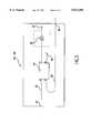
- FIG. 1schematically depicts a bidirectional WDM optical communication system with a bidirectional optical amplifier according to one embodiment of the present invention.
- FIG. 2schematically depicts portions of a gain block configuration useful in the bidirectional optical amplifier of FIG. 1.
- FIG. 3schematically depicts a wavelength selector for use in the bidirectional WDM system of FIG. 1.
- FIG. 4schematically depicts a further embodiment of a bidirectional optical amplifier for use in a bidirectional WDM optical communication system.
- FIG. 1depicts a bidirectional optical communication system 10 according to the present invention.
- Wavelength division multiplexed optical communication system 10includes a plurality of west-east optical transmitters 20 and a plurality of east-west optical transmitters 120.
- the transmission node on the left side of FIG. 1is designated the “west” node
- the transmission node on the right side of FIG. 1is designated the "east” node.
- Each optical transmitter 20 and each optical transmitter 120emits an information-bearing optical signal at a transmission wavelength.
- information -bearing optical signalrefers to an optical signal which has been coded with information, including, but not limited to, audio signals, video signals, and computer data.
- optical transmitters 20deliver wavelengths ⁇ 1 ⁇ 2 ⁇ 3 through ⁇ n corresponding to optical channels 1, 2, 3 through n while optical transmitters 120 deliver wavelengths ⁇ 5 ⁇ 6 ⁇ 7 through ⁇ m corresponding to optical channels 5, 6, 7 through m.
- the bidirectional wavelength division multiplexed optical systems of the present inventionuse a variety of a channel plans and are not limited by the eight-channel bidirectional system depicted in FIG. 1.
- the smallest number of optical channels in a bidirectional WDM optical systemis four, with two channels launched in the west-east direction and two channels launched in the east-west direction.
- the configurations of the present inventionare also useful for systems in which a single channel is launched in each direction.
- the letters "m" and "n"designate the largest channel number in each direction and are any whole number, particularly, m is a whole number with a value of two or larger and n is a whole number with a value of four or larger.
- the optical channel wavelengths emitted by the transmittersare located within the gain spectrum of the optical amplifiers employed in the bidirectional system.
- the west-east optical channel wavelengths emitted by transmitters 20occupy a contiguous spectral region at the shorter wavelength end of the amplifier gain spectrum.
- the east-west optical channels emitted by transmitters 120occupy a contiguous spectral region at the longer wavelength region of the amplifier gain spectrum.
- the system spectrumis typically within a range of approximately 1530 nm to 1560 nm, with the west-east spectral portion occupying 1530-1545 nm and the east-west spectral portion occupying 1546-1560 nm.
- the system spectrum within which the optical transmitter wavelengths are locatedcan correspond to the gain spectrum of any optical amplifiers. Consequently, when using amplifiers with a gain spectrum in a different region, the optical transmitters output wavelengths within that gain spectrum.
- the optical channel wavelengthsare selected to correspond to wavelengths selected by selection components and/or devices of the optical receiving system.
- Each optical transmitter 20, 120generally includes a laser, such as a DFB semiconductor laser, a laser controller, and a modulator for creation of the information-bearing optical signal.
- the transmitter laseris a DFB semiconductor diode laser, generally comprising one or more III-V semiconductor materials, commercially available from a wide variety of suppliers such as Fujitsu, GEC Marconi, Spectra Diode Laboratories, Alcatel, and Hewlett-Packard.
- the laseroutputs an optical carrier signal at a particular channel wavelength corresponding to a demultiplexer wavelength included in a receiving system.
- the laser controllerprovides the required laser bias current as well as thermal control of the laser.
- the precise operating wavelength of the laseris maintained, typically to less than an angstrom bandwidth.
- Exemplary techniques for maintaining the precise operating wavelength of a laserare described in co-pending, commonly-assigned U.S. patent application Ser. No. 08/605,856, filed Feb. 23, 1996 (Attorney's Docket No. 107 mab), now U.S. Pat. No. 5,673,129, the disclosure of which is incorporated by reference herein.
- the optical transmitterseach include a modulator for imparting information to the optical carrier signal.
- An exemplary modulatoris an external modulator, such as a Mach-Zehnder modulator, employing a waveguiding medium whose refractive index changes according to the applied electrical field, i.e., a material exhibiting an electro-optic effect.
- a Mach-Zehnder modulatoremploying a waveguiding medium whose refractive index changes according to the applied electrical field, i.e., a material exhibiting an electro-optic effect.
- two optical interferometer pathsare provided. An incoming optical carrier is split between the two optical paths. At least one path of the interferometer is phase modulated.
- the signalis recombined at the output, the light from the paths either constructively or destructively interferes, depending upon the electrical field applied to the surrounding electrodes during the travel time of the carrier, creating an amplitude-modulated output optical signal.
- a plurality of remodulatorscan be employed. Such remodulators operate to map a space division optical communication system, i.e., a system in which individual optical signals are physically separated in space by transmission on separate waveguides, onto a wavelength division optical communication system, i.e., a communication system in which individual optical signals are simultaneously transmitted in the same waveguide by receiving an information-bearing optical signal at an input and outputting an optical channel having a carrier wavelength corresponding to a demultiplexer wavelength in a WDM optical system.
- the use of optical remodulatorsensures compatibility of optical communication system 10 with currently-deployed transmission equipment. Further description of wavelength division multiplexed optical communication systems with remodulators is found in U.S. Pat. No. 5,504,609, the disclosure of which is incorporated by reference herein.
- optical combiners 30, 130are selected from any passive optical component which can combine plural wavelengths into a single output medium. Frequently, optical splitters used to divide a signal among plural outputs are used as optical combiners, operated in reverse fashion from the splitter. Exemplary optical combiners include 1 ⁇ N wideband single mode splitters available from IOT Integrator Optik GmbH, Waghausel-Kirrlach, Germany, and fused fiber combiners available from Gould, Inc., Millersville, Md.
- Couplers 50, 150are typically three-port optical circulators, as depicted in FIG. 1. In the three-port optical circulator, optical signals which enter circulator port 1 are output to circulator port 2, while optical signals which enter circulator port 2 are output to circulator port 3. In this manner, optical signals are rotated through the optical circulator in the illustrated circulating direction.
- Exemplary optical circulatorsinclude those commercially available from JDS-Fitel, Canada, and E-Tek, San Jose, Calif.
- the west-east WDM optical signalenters coupler 50 through port 52, exiting through port 56 onto transmission path 60 while the east-west WDM optical signal enters coupler 50 through port 56 and exits through port 54 toward the east-west receiving system 80.
- the east-west WDM optical signalenters coupler 150 through port 152 and exits through port 156 onto optical transmission path 60 while the west-east WDM optical signal enters coupler 150 through port 156 and exits through port 154 toward the west-east receiving system 180.
- Optical transmission path 60is typically a single-mode optical fiber such as SMF-28, available from Corning, or TRUEWAVE, available from AT&T Corp./Lucent Technologies, and is the principal transmission medium for the optical communication system.
- SMF-28available from Corning
- TRUEWAVEavailable from AT&T Corp./Lucent Technologies
- any optical waveguide which is capable of transporting multiple optical wavelengthscan be employed as transmission path 60 in optical system 10.
- bidirectional optical amplifier 70Interposed along transmission path 60 is one or more bidirectional optical amplifier 70. While not shown in FIG. 1, it is understood that plural bidirectional optical amplifiers 70 can be positioned along optical transmission path 60. Typically, when WDM optical communication system 10 is used as a long-haul interexchange carrier route, transmission path 60 is on the order of hundreds of kilometers long with optical amplifiers spacings on the order of every 100 kilometers, with a range of 30-130 kilometers being exemplary. Bidirectional amplifiers 70 can also be used as pre- and post-amplifiers in the optical communication system. Amplifier 70 comprises first and second directional optical couplers 72, 74, grating reflector sets 76 and one or more gain blocks 78.
- Directional optical couplers 72 and 74generally comprise the depicted four-port optical circulators. Exemplary optical circulators are commercially available from JDS-Fitel and E-Tek. In the illustrated four-port configuration, the optical signals input to the first circulator port exit the circulator at the second port. Optical signals input to the second port exit the circulator at the third port and optical signals input to the third port exits the circulator at the fourth port. Any optical signals which enter the fourth port (e.g., through Rayleigh scattering) are terminated within the circulator.
- port 2 of optical circulator 72 and port 3 of optical circulator 74communicate with transmission path 60. Port 2 of optical circulator 72 receives the west-east WDM optical signal from transmission path 60 while port 3 of optical circulator 74 receives the east-west WDM optical signal from transmission path 60.
- An optical path 73optically communicates with port 3 of circulator 72 for receiving optical signals originating from circulator port 2.
- Optical path 73terminates at port 4 of optical circulator 74.
- Interposed along optical path 73is Bragg grating set 76.
- an optical path 75optically communicates with port 2 of circulator 74 for receiving optical signals input at port 3.
- Optical path 75terminates at port 1 of optical circulator 72.
- An additional Bragg grating set 76is positioned in optical path 75.
- Bragg grating sets 76comprise one or more Bragg gratings configured to reflect one or more optical signals.
- each Bragg gratingis an in-fiber grating comprising series of photoinduced refractive index perturbations in an optical fiber which reflect optical signals within a selected wavelength band.
- Bragg gratings suitable for use in the optical system of the present inventionknown in the art and are described, inter alia, in Morey et al., "Photoinduced Bragg Gratings in Optical Fibers," Optics and Photonics News, February 1994, pp. 8-14, the disclosure of which is incorporated by reference herein.
- Bragg grating sets 76are configured to reflect optical signals in the west-east spectral band.
- Bragg grating sets 76are configured to reflect optical signals in the east-west spectral band.
- each Bragg grating set 76comprises a single grating which reflects the entire spectral region of the WDM signal for one propagating direction (e.g., a single grating reflecting the band from 1530-1545 nm for the west-east WDM signal or reflecting the band from 1546-1560 nm for the east west WDM signal).
- grating set 76comprises plural Bragg gratings, each of which is configured to reflect one or more optical channels.
- strong gratingsi.e., gratings which reflect over 95% of the incident design wavelength, generally include a radiation mode loss band on the short wavelength side of the transmission/reflection spectrum.
- radiation mode lossdescribes any optical signal loss due to scattering outside the core of the waveguide, including radiation scattered in the cladding of the waveguide, and is caused by the grating presence within the core, and not the cladding, of the optical waveguide. Consequently, it is desirable to ensure that optical channels are not located within the radiation mode loss region for grating set 76.
- the west-east optical channels reflected by the gratingare selected to have shorter wavelengths than the east-west optical channels which, as described below, are transmitted through the grating.
- the transmitted signal wavelengthswill all pass through the grating transmission region at wavelengths longer than the reflected wavelengths, i.e., the region in which there is no radiation mode loss associated with the grating.
- the east-west optical channelsare selected to have shorter wavelengths that the west-east optical channels which are transmitted through the gratings.
- grating set 76alternatively comprises a series of gratings, each grating configured to reflect one or more channels within the desired spectral region.
- This configurationadvantageously reduces the problem of radiation mode loss since narrow gratings exhibit proportionally less radiation mode loss than strong, wide, gratings.
- the gratingsare ordered such that the shortest channel wavelength is reflected first, in order up to the longest channel wavelength, to eliminate radiation mode loss effects during reflection.
- gain block 78Interconnecting the fourth port of circulator 72 and the first port of circulator 74 is gain block 78 which produces optical gain in the optical transmission signals that traverse the fiber.
- gain block 78is selected from a number of devices and/or components and can have a variety of configurations.
- gain block 78is a rare-earth doped fiber amplifier.
- the west-east WDM optical signalenters port 2 of circulator 72.
- the west WDM signalexits circulator 72 through port 3, it is placed on optical path 73 where it encounters grating set 76 and is reflected back toward circulator port 3.
- the west signalre-enters circulator 72 through port 3 and is output through port 4.
- the west WDM signalis optically amplified as it traverses gain block 78.
- the amplified west WDM signalenters the second optical circulator 74 through port 1 and is output through port 2.
- the west WDM signalexits circulator 74 through port 2
- itis placed on optical path 75 and reflected back towards port 2 by grating 76.
- the west WDM optical signalis subsequently output through port 3 of circulator 74 and placed onto optical transmission path 60 to continue travelling toward the east node.
- the east-west WDM optical signalenters circulator 74 from optical transmission path 60 through circulator port 3.
- the east WDM signalexits through port 4 and traverses optical path 73 (unimpeded by grating 76) and enters circulator 72 through port 3.
- the east WDM signalis passed through to port 4 where it exits towards gain block 78 for optical amplification.
- the east optical signalenters circulator 74 through port 1, exiting through port 2 onto optical path 75.
- the amplified east optical signaltraverses optical path 75, (unimpeded by grating 76) and enters circulator 72, through port 1, exiting through port 2 onto optical transmission path 60 to continue propagation toward the west node.
- gain block 78is selected from any component or device which produces optical gain to incident optical signals.
- gain block 78is selected from doped fiber amplifiers, semiconductor amplifiers, and Raman amplifiers.
- gain block 78is the multiple-stage rare-earth-doped fiber gain block 78 depicted in FIG. 2.
- Gain blockincludes a first and second amplifier stages 161 and 162. Each of the first and second stages includes a length of doped optical waveguide in which the dopant is selected from materials which can produce laser action in the waveguide. Such materials include rare earth dopants such as erbium, neodymium, praseodymium, ytterbium, or mixtures thereof.
- exemplary erbium-doped fiber 161is commercially available from Alcatel, Corning, Inc., AT&T Corp./Lucent Technologies, Lycom, and Furukawa Corp.
- pump connection elements 165 and 166are provided to connect each stage of the amplifier with a source of optical pumping energy.
- Pump connection elements 165 and 166are typically wavelength selective multiplexers which permit pump radiation to enter the doped fiber sections without allowing transmission channel radiation to pass into the pump.
- Optical pumping elementsare generally selected from 980 and 1480 nm laser sources. In one embodiment, a 980 nm pump, depicted as element 163, can be used to pump the first stage of the amplifier while a 1480 nm pump, depicted as element 164, is used to pump the second stage of the amplifier.
- a single laser sourcecomprising single or multiple laser diodes, can be used to pump both fiber sections or to pump two amplifier stages located in separate optical amplifiers.
- isolator 167is optionally positioned between the first and second amplifier stages.
- the amplifier stagesare interconnected through interconnection element 168, selected to be a four-port wavelength division multiplexer.
- Multiplexer 168includes at least one wavelength selective member 169 for selecting one or more optical service channels to enter and exit the communication system.
- Wavelength selective member 169can be a multilayer thin film interference filter constructed to reflect an optical monitoring channel, particularly an optical service channel having a wavelength outside the gain band of the doped-fiber amplifier.
- the interconnection element 168includes means for selectively passing a particular wavelength range. In an exemplary embodiment, interconnection element selects wavelengths which are 1540 nm and above.
- the multilayer thin film interference filters 169 employed in the optical amplifiers of the present inventionare commercially available from JDS-Fitel, Canada.
- member 169is configured to reflect optical signals having a wavelengths of 1625 nm or greater, a wavelength band outside the gain band of the selected erbium fiber.
- An optical channel in this bandis used as an optical monitoring/service channel and a service channel transmitter/receiver communicates with the interconnection element for sending and detecting this channel.
- the payload optical channelsi.e., those WDM signal channels having wavelengths within the gain band of the optical amplifier, pass through wavelength selective member 169 unaffected.
- the service channelis launched from the east node.
- interconnection element 168is depicted as a multilayer interference filter, it is understood that a variety of interconnection elements can be positioned between the first and second amplifier stages, depending upon the overall WDM system configuration.
- interconnection element 168can be selected from optical circulators which include devices such as Bragg gratings configured for ASE reduction, as described in U.S. Pat. 5,283,626, the disclosure of which is incorporated herein by reference.
- other optical filtering elementscan be used for interconnection element 168 depending upon wavelengths desired to pass through to the second amplifier stage. Additional elements may be used in conjunction with gain block 78 such as the depicted isolators 167 at the amplifier input and output which exclude reflected optical signals.
- the west-east WDM optical signalenters coupler 150 through port 156, exiting onto output path 155 through output port 154.
- the east-west WDM optical signalenters coupler 50 through port 56, exiting onto output path 55.
- each channelmust be demultiplexed and routed to the receiver designated for the particular channel. This function is performed by west-east receiving system 180 and east-west receiving system. It is understood that the depicted receiving systems are exemplary; any system which can receive a multiplexed optical signal, demultiplex the signal into the constituent optical channels, and route the individual channels to their respective receivers can be employed as the receiving systems 80, 180 in the optical communication systems of the present invention.
- the multiplexed signalsare input to optical splitters 82, 182 respectively through input ports 83, 183.
- the optical splittersplace a portion of the multiplexed signals onto each of plural output paths 84, 184.
- Each output path 84, 184optically communicates with a demultiplexer wavelength selector system 90, 190.
- Optical splitters 82, 182are selected from optical devices which can divide an input optical signal and place it onto plural output paths. Exemplary splitters include passive optical components such as those components described for use as optical combiners 30, 130.
- wavelength selectors 90, 192are presented. While the wavelength selector elements are depicted with reference numerals directed only to wavelength selectors 90, it is understood that substantially similar components are found in wavelength selector 190.
- the output portions of the WDM optical signals from splitters 82, 182enter each of wavelength selectors 90, 190 through input ports 92, 192 and are placed onto optical path 93.
- Optical path 93typically an optical fiber, passes the WDM signal into coupler 94.
- Coupler 94is typically a 3 dB fused fiber coupler.
- the WDM optical signal entering coupler 94 through port Ais equally divided between output ports C and D.
- the portion of the optical signal exiting the coupler through port Dpasses through low reflectivity port 96 and exits the optical system.
- the low reflectivity port 96is typically an angled fiber cut, although any low reflectivity waveguide termination technique may be employed.
- optical filter 95The portion of the WDM optical signal which exits coupler 94 through port C encounters optical filter 95.
- the optical filterpasses optical signals having wavelengths other than the channel wavelength to be sent to the optical channel receiver. These non-selected channels pass through low reflectivity port 97 and exit the optical communication system.
- the channel wavelengthis reflected by optical filter 95 to be routed towards the optical receiver back through coupler 94, exiting onto optical path 98 through coupler port B.
- optical filter 95is a Bragg grating configured to reflect a particular optical channel.
- Bragg gratingsare exemplary optical filters, it is understood that other types of Bragg gratings can be employed as optical filter 95, including, but not limited to, bulk gratings, e.g., photoinduced refractive index perturbations in bulk optical media.
- the term "Bragg gratings”encompasses in-fiber, waveguide, and bulk versions of these optical components. Since each wavelength selector 90,192 selects a designated optical channel to be routed to the respective optical receiver, each Bragg grating reflects a different optical channel. The selected optical channels exit wavelength selectors 90, 190 through selector output ports 99, 199.
- any demultiplexer configurationmay be used to separate the individual optical channels from the WDM optical signals.
- Other demultiplexer configurations for use in the present inventioninclude those described in U.S. Pat. Nos. 5,457,760 and 5,475,780, incorporated by reference above, demultiplexers based on wavelength routers, commercially available from AT&T Corp./Lucent Technologies, Fabry-Perot demultiplexers, and interference filter demultiplexers.
- the channel wavelengthsare input to their respective optical receivers 88, 188 through receiver inputs 89, 189.
- the signalmay be optically amplified before it reaches the receiver.
- the optical receivergenerally detects the optical signal and converts it to an electrical signal, typically through the use of a photodiode device.
- Various optical receivers suitable for use in optical system 10are described in Gowar, Optical Communication Systems, discussed above. In optical communication system 10, the receiver will frequently be part of an existing optical communication system to which the optical channel is routed. Consequently, the optical system 10 can function with numerous types of receivers to ensure compatibility with existing optical equipment.
- FIG. 4depicts a further embodiment of a bidirectional optical amplifier according to the present invention.
- Bidirectional optical amplifier 170comprises four three-port optical circulators 171, 172, 173, and 174, grating reflectors 76 and gain block 78.
- Exemplary three-port optical circulatorsare commercially available from JDS-Fitel and E-Tek.
- the optical signals input to the first circulator portexit the circulator at the second port.
- Optical signals input to the second portexit the circulator at the third port.
- Optical signals which inadvertantly enter the third portare terminated within the circulator.
- port 2 of optical circulator 171 and port 2 of optical circulator 173communicate with transmission path 60.
- Port 2 of optical circulator 171receives the west-east WDM optical signal from transmission path 60 while port 2 of optical circulator 171 receives the east-west WDM optical signal from transmission path 60.
- An optical path 175optically communicates with port 3 of circulator 171 for receiving optical signals originating from circulator port 2.
- Optical path 175terminates at port 1 of optical circulator 172.
- Optical path 177optically communicates with port 2 of circulator 172 for receiving optical signals from circulator port 1 and terminates at port 3 of circulator 173. Interposed along optical path 177 is Bragg grating set 76.
- Bragg grating set 76is substantially similar to grating set 76 of FIG. 1 and comprises, in an exemplary embodiment, one or more Bragg gratings configured to reflect optical signals in the west-east spectral band.
- optical path 176having a grating set 76 positioned therein, optically communicates with port 1 of circulator 171 and port 2 of circulator 174.
- optical path 178Interconnecting the third port of circulator 172 and the first port of circulator 174 is optical path 178 having gain block 78 positioned therein.
- gain block 78produces optical gain in the optical transmission signals traversing optical path 178 and is selected from the various optical gain configurations discussed in connection with FIG. 2, above.
- Optical path 179interconnects the third port of circulator 174 with the first port of circulator 173.
- any two of the three-port optical circulators 171, 172, 173, and 174can be replaced by a single six-port circulator, with the same amplifier function.
- the west-east WDM optical signalenters port 2 of circulator 171.
- the west WDM signalexits circulator 171 through port 3, it traverses optical path 173 and enters circulator 172 through port 1.
- the west signalexits circulator 172 through port 2 and is placed on optical path 177, it encounters grating set 76 and is reflected back toward circulator port 2 of circulator 172.
- the west signalre-enters circulator 172 through port 2 and is output through port 2.
- the west signalexits through the third port onto optical path 178, it is optically amplified as it traverses gain block 78.
- the amplified west WDM signalenters the optical circulator 174 through port 1 and is output through port 2.
- the west WDM signalexits circulator 174 through port 2, it is placed on optical path 176 and reflected back towards port 2 by grating 76.
- the west WDM optical signalre-enters circulator 174 through port 2 and is subsequently output through port 3 onto optical path 179.
- the west optical signalthen enters circulator 173 through port 1 where it is circulated to port 2 and output through port 2 onto optical transmission path 60 to continue travelling toward the east node.
- the east-west WDM optical signalenters circulator 173 from optical transmission path 60 through circulator port 2.
- the east WDM signalexits through port 3 and traverses optical path 177 (unimpeded by grating set 76) entering circulator 172 through port 2.
- the east WDM signalis circulated to port 3, output onto optical path 178, and is optically amplified as it traverses gain block 78.
- the east optical signalenters circulator 174 through port 1, exiting through port 2 onto optical path 176.
- the amplified east optical signaltraverses optical path 176, (unimpeded by grating 76) and enters circulator 171, through port 1, exiting through port 2 onto optical transmission path 60 to continue propagation toward the west node.
Landscapes
- Engineering & Computer Science (AREA)
- Computer Networks & Wireless Communication (AREA)
- Signal Processing (AREA)
- Physics & Mathematics (AREA)
- Electromagnetism (AREA)
- Optical Communication System (AREA)
Abstract
Description
Claims (17)
Priority Applications (1)
| Application Number | Priority Date | Filing Date | Title |
|---|---|---|---|
| US08/663,624US5812306A (en) | 1996-06-14 | 1996-06-14 | Bidirectional WDM optical communication systems with bidirectional optical amplifiers |
Applications Claiming Priority (1)
| Application Number | Priority Date | Filing Date | Title |
|---|---|---|---|
| US08/663,624US5812306A (en) | 1996-06-14 | 1996-06-14 | Bidirectional WDM optical communication systems with bidirectional optical amplifiers |
Publications (1)
| Publication Number | Publication Date |
|---|---|
| US5812306Atrue US5812306A (en) | 1998-09-22 |
Family
ID=24662627
Family Applications (1)
| Application Number | Title | Priority Date | Filing Date |
|---|---|---|---|
| US08/663,624Expired - LifetimeUS5812306A (en) | 1996-06-14 | 1996-06-14 | Bidirectional WDM optical communication systems with bidirectional optical amplifiers |
Country Status (1)
| Country | Link |
|---|---|
| US (1) | US5812306A (en) |
Cited By (69)
| Publication number | Priority date | Publication date | Assignee | Title |
|---|---|---|---|---|
| US5978131A (en)* | 1998-04-07 | 1999-11-02 | Institut National D'optique | In-fiber two-stage amplifier providing WDM signal conditioning |
| EP0994584A1 (en)* | 1998-10-15 | 2000-04-19 | Alcatel | Repeater for a long-haul optical fiber transmission system using WDM |
| AU720392B2 (en)* | 1996-11-06 | 2000-06-01 | Corning Incorporated | Crosstalk suppression in a multipath optical amplifier |
| US6097533A (en)* | 1997-10-21 | 2000-08-01 | Antec Corporation | Optical amplifier for CATV system with forward and reverse paths |
| US6130775A (en)* | 1997-09-30 | 2000-10-10 | Daewoo Telecom Ltd. | Bidirectional optical fiber amplifier |
| US6160660A (en)* | 1997-12-31 | 2000-12-12 | Pirelli Cavi E Sistemi S.P.A. | Bidirectional optical transmission system for dense interleaved wavelength division multiplexing |
| US6175444B1 (en)* | 1997-12-02 | 2001-01-16 | Nec Corporation | Bi-directional optical amplifier |
| US6201904B1 (en)* | 1999-01-27 | 2001-03-13 | Nec Corporation | Optical demultiplex circuit |
| US6212000B1 (en)* | 1998-01-14 | 2001-04-03 | Nec Corporation | Two-way optical amplifier module |
| WO2001025846A1 (en)* | 1999-10-06 | 2001-04-12 | Codeon Corporation | Apparatus for externally modulating two optical channels at the same time |
| US6236499B1 (en)* | 1999-04-15 | 2001-05-22 | Nortel Networks Limited | Highly scalable modular optical amplifier based subsystem |
| US6243177B1 (en) | 2000-10-03 | 2001-06-05 | Seneca Networks, Inc. | Bidirectional WDM optical communication system with bidirectional add-drop multiplexing |
| US6275331B1 (en)* | 1999-06-30 | 2001-08-14 | Nortel Networks Limited | Optical amplifiers |
| US6288812B1 (en)* | 2000-11-03 | 2001-09-11 | Seneca Networks | Bidirectional WDM optical communication network with optical bridge between bidirectional optical waveguides |
| ES2159239A1 (en)* | 1999-06-11 | 2001-09-16 | Televisio De Catalunya S A | Fibre optic transmission system |
| US6313933B1 (en)* | 1997-05-15 | 2001-11-06 | Nec Corporation | Bidirectional wavelength division multiplex transmission apparatus |
| US6321004B1 (en)* | 2001-04-24 | 2001-11-20 | Seneca Networks | Protection switching in bidirectional WDM optical communication networks |
| US6327402B1 (en)* | 1999-02-04 | 2001-12-04 | Lucent Technologies, Inc. | Lightwave transmission system having wide pump wavebands |
| US6333798B1 (en) | 2001-02-13 | 2001-12-25 | Seneca Networks, Inc. | Bidirectional WDM optical communication network |
| US6339663B1 (en)* | 2000-12-22 | 2002-01-15 | Seneca Networks, Inc. | Bidirectional WDM optical communication system with bidirectional optical service channels |
| US6348985B1 (en)* | 2000-12-08 | 2002-02-19 | Seneca Networks | Bidirectional WDM optical communication network with data bridging plural optical channels between bidirectional optical waveguides |
| US6381065B1 (en) | 1999-03-26 | 2002-04-30 | Tycom (Us) Inc. | Optical pump unit for an optical amplifier |
| WO2002039636A1 (en)* | 2000-11-03 | 2002-05-16 | Seneca Networks, Inc. | Bidirectional wdm optical communication network with optical bridge between bidirectional optical waveguides |
| WO2002047307A1 (en)* | 2000-12-08 | 2002-06-13 | Seneca Networks, Inc. | Wdm optical communication network with data bridging plural optical channels between optical waveguides |
| US6407846B1 (en) | 2001-03-16 | 2002-06-18 | All Optical Networks, Inc. | Photonic wavelength shifting method |
| US20020089719A1 (en)* | 2001-01-09 | 2002-07-11 | Young-Hoon Joo | Bidirectional WDM add/drop multiplexer and bidirectional WDM optical transmission system having the same |
| US20020118446A1 (en)* | 2001-02-23 | 2002-08-29 | Chang-Hee Lee | Bi-directional optical-amplifier module |
| US20020131125A1 (en)* | 2001-03-16 | 2002-09-19 | Myers Michael H. | Replicated-spectrum photonic transceiving |
| US6459528B1 (en) | 2000-05-23 | 2002-10-01 | Avanex Corporation | Optical passive components and bi-directional amplifier |
| US20020141046A1 (en)* | 2001-04-02 | 2002-10-03 | Young-Hoon Joo | Optical amplifier device and bidirectional wavelength division multiplexing optical communication system using the same |
| US6480326B2 (en) | 2000-07-10 | 2002-11-12 | Mpb Technologies Inc. | Cascaded pumping system and method for producing distributed Raman amplification in optical fiber telecommunication systems |
| US6493117B1 (en) | 1997-08-27 | 2002-12-10 | Nortel Networks Limited | WDM optical network with passive pass-through at each node |
| US6493133B1 (en)* | 2000-06-30 | 2002-12-10 | Tyco Telecommunications (Us) Inc. | System and method for increasing capacity of undersea cables |
| US6496305B2 (en)* | 2001-03-28 | 2002-12-17 | Sycamore Networks, Inc. | Two fiber support with single optical amplifier |
| US20020196504A1 (en)* | 2001-05-29 | 2002-12-26 | Nec Corporation | Gain equalizer for two-way transmission and monitor circuit for two-way transmission |
| US20030081285A1 (en)* | 2001-10-26 | 2003-05-01 | Naomasa Shimojoh | Transmission device having wavelength-band-specific optical amplifiers provided commonly for all transmission lines |
| EP1309111A1 (en)* | 2001-10-30 | 2003-05-07 | Mitsubishi Denki Kabushiki Kaisha | Method of and device for performing bi-directional transmission using a single-wire |
| US6602002B1 (en)* | 1998-02-20 | 2003-08-05 | Lucent Technologies Inc. | High capacity optical transmission arrangement |
| US20030151802A1 (en)* | 1999-04-15 | 2003-08-14 | Loren Berg | Highly scalable modular optical amplifier based subsystem |
| US6608709B2 (en) | 2000-10-03 | 2003-08-19 | Gary Duerksen | Bidirectional WDM optical communication system with bidirectional add-drop multiplexing |
| US20030235215A1 (en)* | 2002-03-28 | 2003-12-25 | Carrel John Robert | Apparatus and method for aggregation and transportation for plesiosynchronous framing oriented data formats |
| US20040042067A1 (en)* | 2002-06-04 | 2004-03-04 | Eiselt Michael H. | Apparatus and method for duplex optical transport using a co-directional optical amplifier |
| US6704512B1 (en) | 1998-12-10 | 2004-03-09 | Lg Information & Communications, Ltd. | WDM optical channel dispersion compensating and monitoring apparatus and optical amplifier comprising the apparatus |
| WO2004028056A1 (en)* | 2002-09-18 | 2004-04-01 | The University Of Melbourne | Improved optical amplifier and/or add/drop structure |
| US20040109235A1 (en)* | 2002-11-26 | 2004-06-10 | Johnny Zhong | Batched package process for creating optical blocks for use in forming optical components |
| US20040114870A1 (en)* | 2002-11-26 | 2004-06-17 | Johnny Zhong | Optical add/drop patch cord |
| US20040161214A1 (en)* | 2002-03-15 | 2004-08-19 | Satoshi Kajiya | One-core two-way optical transmission system |
| US20040170434A1 (en)* | 2000-03-02 | 2004-09-02 | Nec Corporation | Optical amplifier, optical amplifying repeater and transmission apparatus of wavelength division multiplexed signal light using the same |
| US20040175187A1 (en)* | 2002-12-13 | 2004-09-09 | Eiselt Michael H. | Single fiber duplex optical transport |
| US20050031349A1 (en)* | 2003-08-09 | 2005-02-10 | Sung-Bum Park | Bidirectional optical add-drop multiplexer |
| US20050068649A1 (en)* | 2001-07-06 | 2005-03-31 | Chang-Joon Chae | Optical add/drop structures |
| US20050078909A1 (en)* | 2002-11-26 | 2005-04-14 | Johnny Zhong | Optical add/drop module |
| US20050180683A1 (en)* | 2002-03-07 | 2005-08-18 | Barry Luther-Davies | Tuneable filter arrangement |
| RU2264011C1 (en)* | 2004-03-24 | 2005-11-10 | Федеральное государственное предприятие "Научно-производственное предприятие "Исток" (ФГУП НПП "Исток") | Method for exciting radiation pulses of laser systems built around self-restrained junctions (alternatives) |
| US6993286B2 (en) | 2002-08-02 | 2006-01-31 | Radio Frequency Systems, Inc. | Dual band bidirectional amplifier for wireless communication |
| US20060029393A1 (en)* | 2004-08-09 | 2006-02-09 | Samsung Electronics Co., Ltd | Wideband optical module and PON using the same |
| US7054522B1 (en)* | 2004-12-09 | 2006-05-30 | Electronics And Telecommunications Research Institute | Bidirectional optical recirculation loop transmitting device |
| US20070003283A1 (en)* | 2005-06-29 | 2007-01-04 | At&T Corp. | Dynamic allocation of bandwidth in a bidirectional optical transmission system |
| US20070098405A1 (en)* | 2005-11-01 | 2007-05-03 | Technology Advancement Group | Method and system for bi-directional communication over a single optical fiber |
| US7228025B1 (en)* | 2002-10-31 | 2007-06-05 | Finisar Corporation | Thin film interleaver |
| CN100345345C (en)* | 2003-05-14 | 2007-10-24 | 日本电气株式会社 | Single optical fibre bidirectional optical transmission system and single optical fibre bidirectional optical amplifier |
| US7346280B1 (en)* | 2002-03-15 | 2008-03-18 | Cisco Technology, Inc. | Bi-directional long haul/ultra long haul optical communication link |
| US7656905B2 (en) | 2002-12-24 | 2010-02-02 | Samir Sheth | Apparatus and method for aggregation and transportation of gigabit ethernet and other packet based data formats |
| US7782778B2 (en) | 2002-12-24 | 2010-08-24 | Samir Satish Sheth | Apparatus and method for fibre channel distance extension embedded within an optical transport system |
| US20110200329A1 (en)* | 2005-11-01 | 2011-08-18 | Technology Advancement Group, Inc. | Method and system for bi-directional communication over a single optical fiber |
| US20140294337A1 (en)* | 2011-10-10 | 2014-10-02 | U2T Photonics Uk Limited | Optical iq modulator |
| CN104917042A (en)* | 2015-06-19 | 2015-09-16 | 中国科学院上海光学精密机械研究所 | Low-noise and high-symmetry bidirectional optical amplifier applied to optical fiber time-frequency transmission |
| US9500596B2 (en) | 2011-07-27 | 2016-11-22 | Omnisens Sa | Sensor and method of sensing |
| US9606234B2 (en) | 2013-10-18 | 2017-03-28 | Tramontane Technologies, Inc. | Amplified optical circuit |
Citations (9)
| Publication number | Priority date | Publication date | Assignee | Title |
|---|---|---|---|---|
| EP0535590A2 (en)* | 1991-09-30 | 1993-04-07 | Nec Corporation | Two-way repeater employing optical amplification |
| US5280549A (en)* | 1993-02-05 | 1994-01-18 | National Research Council Of Canada | Frequency dependent optical isolator |
| US5479082A (en)* | 1993-08-10 | 1995-12-26 | Cselt-Centro Studi E Laboratorti Telecommunicazioni S.P.A. | Device for extraction and re-insertion of an optical carrier in optical communications networks |
| US5500763A (en)* | 1993-11-05 | 1996-03-19 | Fuji Xerox Co., Ltd. | Transmitter-receiver and optical amplifier for optical communication |
| US5532864A (en)* | 1995-06-01 | 1996-07-02 | Ciena Corporation | Optical monitoring channel for wavelength division multiplexed optical communication system |
| US5557442A (en)* | 1993-06-04 | 1996-09-17 | Ciena Corporation | Optical amplifiers with flattened gain curves |
| US5563733A (en)* | 1994-08-25 | 1996-10-08 | Matsushita Electric Industrial Co., Ltd. | Optical fiber amplifier and optical fiber transmission system |
| US5633741A (en)* | 1995-02-23 | 1997-05-27 | Lucent Technologies Inc. | Multichannel optical fiber communications |
| US5638473A (en)* | 1994-11-16 | 1997-06-10 | Northern Telecom Limited | Optical waveguide grating filter |
- 1996
- 1996-06-14USUS08/663,624patent/US5812306A/ennot_activeExpired - Lifetime
Patent Citations (10)
| Publication number | Priority date | Publication date | Assignee | Title |
|---|---|---|---|---|
| EP0535590A2 (en)* | 1991-09-30 | 1993-04-07 | Nec Corporation | Two-way repeater employing optical amplification |
| US5652675A (en)* | 1991-09-30 | 1997-07-29 | Nec Corporation | Two-way repeater employing optical amplification |
| US5280549A (en)* | 1993-02-05 | 1994-01-18 | National Research Council Of Canada | Frequency dependent optical isolator |
| US5557442A (en)* | 1993-06-04 | 1996-09-17 | Ciena Corporation | Optical amplifiers with flattened gain curves |
| US5479082A (en)* | 1993-08-10 | 1995-12-26 | Cselt-Centro Studi E Laboratorti Telecommunicazioni S.P.A. | Device for extraction and re-insertion of an optical carrier in optical communications networks |
| US5500763A (en)* | 1993-11-05 | 1996-03-19 | Fuji Xerox Co., Ltd. | Transmitter-receiver and optical amplifier for optical communication |
| US5563733A (en)* | 1994-08-25 | 1996-10-08 | Matsushita Electric Industrial Co., Ltd. | Optical fiber amplifier and optical fiber transmission system |
| US5638473A (en)* | 1994-11-16 | 1997-06-10 | Northern Telecom Limited | Optical waveguide grating filter |
| US5633741A (en)* | 1995-02-23 | 1997-05-27 | Lucent Technologies Inc. | Multichannel optical fiber communications |
| US5532864A (en)* | 1995-06-01 | 1996-07-02 | Ciena Corporation | Optical monitoring channel for wavelength division multiplexed optical communication system |
Non-Patent Citations (4)
| Title |
|---|
| Barnard et al, IEEE Photonics Tech. Lett., vol. 4, No. 8, Aug. 1992, pp. 911 913; abst. only herewith.* |
| Barnard et al, IEEE Photonics Tech. Lett., vol. 4, No. 8, Aug. 1992, pp. 911-913; abst. only herewith. |
| Chawbi et al, 21st Eurgren Conf. on Opt. Commun., vol. 1, pp. 47 50, Sep. 21, 1995; abst. only herewith.* |
| Chawbi et al, 21st Eurgren Conf. on Opt. Commun., vol. 1, pp. 47-50, Sep. 21, 1995; abst. only herewith. |
Cited By (108)
| Publication number | Priority date | Publication date | Assignee | Title |
|---|---|---|---|---|
| US6084704A (en)* | 1996-11-06 | 2000-07-04 | Corning Incorporated | Crosstalk suppression in a multipath optical amplifier |
| US6342966B1 (en)* | 1996-11-06 | 2002-01-29 | Corning Incorporated | Crosstalk suppression in a multipath optical amplifier |
| AU720392B2 (en)* | 1996-11-06 | 2000-06-01 | Corning Incorporated | Crosstalk suppression in a multipath optical amplifier |
| US6313933B1 (en)* | 1997-05-15 | 2001-11-06 | Nec Corporation | Bidirectional wavelength division multiplex transmission apparatus |
| US6748174B2 (en) | 1997-08-27 | 2004-06-08 | Nortel Networks Limited | WDM optical network with passive pass-through at each node |
| US6757498B2 (en) | 1997-08-27 | 2004-06-29 | Nortel Networks Limited | WDM optical network with passive pass-through at each node |
| US6751418B2 (en) | 1997-08-27 | 2004-06-15 | Nortel Networks Limited | WDM optical network with passive pass-through at each node |
| US6775479B2 (en) | 1997-08-27 | 2004-08-10 | Nortel Networks Corporation | WDM optical network with passive pass-through at each node |
| US6795652B2 (en) | 1997-08-27 | 2004-09-21 | Nortel Networks Limited | WDM optical network with passive pass-through at each node |
| US6529300B1 (en) | 1997-08-27 | 2003-03-04 | Nortel Networks Limited | WDM optical network with passive pass-through at each node |
| US6556321B1 (en) | 1997-08-27 | 2003-04-29 | Nortel Networks Limited | WDM optical network and switching node with pilot tone communications |
| US6493117B1 (en) | 1997-08-27 | 2002-12-10 | Nortel Networks Limited | WDM optical network with passive pass-through at each node |
| US6631018B1 (en) | 1997-08-27 | 2003-10-07 | Nortel Networks Limited | WDM optical network with passive pass-through at each node |
| US6892032B2 (en) | 1997-08-27 | 2005-05-10 | Nortel Networks Limited | WDM optical network with passive pass-through at each node |
| US6563615B2 (en) | 1997-08-27 | 2003-05-13 | Nortel Networks Limited | Technique for detecting noise on a data channel |
| US6130775A (en)* | 1997-09-30 | 2000-10-10 | Daewoo Telecom Ltd. | Bidirectional optical fiber amplifier |
| US6097533A (en)* | 1997-10-21 | 2000-08-01 | Antec Corporation | Optical amplifier for CATV system with forward and reverse paths |
| US6175444B1 (en)* | 1997-12-02 | 2001-01-16 | Nec Corporation | Bi-directional optical amplifier |
| US6160660A (en)* | 1997-12-31 | 2000-12-12 | Pirelli Cavi E Sistemi S.P.A. | Bidirectional optical transmission system for dense interleaved wavelength division multiplexing |
| US6212000B1 (en)* | 1998-01-14 | 2001-04-03 | Nec Corporation | Two-way optical amplifier module |
| US6602002B1 (en)* | 1998-02-20 | 2003-08-05 | Lucent Technologies Inc. | High capacity optical transmission arrangement |
| US5978131A (en)* | 1998-04-07 | 1999-11-02 | Institut National D'optique | In-fiber two-stage amplifier providing WDM signal conditioning |
| FR2784826A1 (en)* | 1998-10-15 | 2000-04-21 | Cit Alcatel | REPEATER FOR WAVELENGTH MULTIPLEXED LONG-RANGE FIBER OPTIC TRANSMISSION SYSTEM |
| EP0994584A1 (en)* | 1998-10-15 | 2000-04-19 | Alcatel | Repeater for a long-haul optical fiber transmission system using WDM |
| US6704512B1 (en) | 1998-12-10 | 2004-03-09 | Lg Information & Communications, Ltd. | WDM optical channel dispersion compensating and monitoring apparatus and optical amplifier comprising the apparatus |
| US6201904B1 (en)* | 1999-01-27 | 2001-03-13 | Nec Corporation | Optical demultiplex circuit |
| US6327402B1 (en)* | 1999-02-04 | 2001-12-04 | Lucent Technologies, Inc. | Lightwave transmission system having wide pump wavebands |
| US6381065B1 (en) | 1999-03-26 | 2002-04-30 | Tycom (Us) Inc. | Optical pump unit for an optical amplifier |
| US20030151802A1 (en)* | 1999-04-15 | 2003-08-14 | Loren Berg | Highly scalable modular optical amplifier based subsystem |
| US6236499B1 (en)* | 1999-04-15 | 2001-05-22 | Nortel Networks Limited | Highly scalable modular optical amplifier based subsystem |
| US6757098B2 (en)* | 1999-04-15 | 2004-06-29 | Nortel Network Limited | Highly scalable modular optical amplifier based subsystem |
| ES2159239A1 (en)* | 1999-06-11 | 2001-09-16 | Televisio De Catalunya S A | Fibre optic transmission system |
| US6275331B1 (en)* | 1999-06-30 | 2001-08-14 | Nortel Networks Limited | Optical amplifiers |
| WO2001025846A1 (en)* | 1999-10-06 | 2001-04-12 | Codeon Corporation | Apparatus for externally modulating two optical channels at the same time |
| US6330098B1 (en) | 1999-10-06 | 2001-12-11 | Codeon Corporation | Apparatus for externally modulating two optical channels at the same time |
| US20050088725A1 (en)* | 2000-03-02 | 2005-04-28 | Nec Corporation | Optical amplifier, optical amplifying repeater and transmission apparatus of wavelength division multiplexed signal light using the same |
| US20040170434A1 (en)* | 2000-03-02 | 2004-09-02 | Nec Corporation | Optical amplifier, optical amplifying repeater and transmission apparatus of wavelength division multiplexed signal light using the same |
| US20050094251A1 (en)* | 2000-03-02 | 2005-05-05 | Nec Corporation | Optical amplifier, optical amplifying repeater and transmission apparatus of wavelength division multiplexed signal light using the same |
| US20050185258A1 (en)* | 2000-03-02 | 2005-08-25 | Nec Corporation | Optical amplifier, optical amplifying repeater and transmission apparatus of wavelength division multiplexed signal light using the same |
| US6459528B1 (en) | 2000-05-23 | 2002-10-01 | Avanex Corporation | Optical passive components and bi-directional amplifier |
| US20040051939A1 (en)* | 2000-05-23 | 2004-03-18 | Avanex Corporation | Optical passive components and bi-directional amplifier |
| US6643056B2 (en) | 2000-05-23 | 2003-11-04 | Avanex Corporation | Optical passive components and bi-directional amplifier |
| US6493133B1 (en)* | 2000-06-30 | 2002-12-10 | Tyco Telecommunications (Us) Inc. | System and method for increasing capacity of undersea cables |
| US6480326B2 (en) | 2000-07-10 | 2002-11-12 | Mpb Technologies Inc. | Cascaded pumping system and method for producing distributed Raman amplification in optical fiber telecommunication systems |
| US6608709B2 (en) | 2000-10-03 | 2003-08-19 | Gary Duerksen | Bidirectional WDM optical communication system with bidirectional add-drop multiplexing |
| US6243177B1 (en) | 2000-10-03 | 2001-06-05 | Seneca Networks, Inc. | Bidirectional WDM optical communication system with bidirectional add-drop multiplexing |
| WO2002039636A1 (en)* | 2000-11-03 | 2002-05-16 | Seneca Networks, Inc. | Bidirectional wdm optical communication network with optical bridge between bidirectional optical waveguides |
| US6288812B1 (en)* | 2000-11-03 | 2001-09-11 | Seneca Networks | Bidirectional WDM optical communication network with optical bridge between bidirectional optical waveguides |
| WO2002047307A1 (en)* | 2000-12-08 | 2002-06-13 | Seneca Networks, Inc. | Wdm optical communication network with data bridging plural optical channels between optical waveguides |
| US6348985B1 (en)* | 2000-12-08 | 2002-02-19 | Seneca Networks | Bidirectional WDM optical communication network with data bridging plural optical channels between bidirectional optical waveguides |
| US6411412B1 (en)* | 2000-12-08 | 2002-06-25 | Seneca Networks | WDM optical communication network with data bridging plural optical channels between optical waveguides |
| US6339663B1 (en)* | 2000-12-22 | 2002-01-15 | Seneca Networks, Inc. | Bidirectional WDM optical communication system with bidirectional optical service channels |
| EP1221779A3 (en)* | 2001-01-09 | 2005-11-16 | Samsung Electronics Co., Ltd. | Bidirectional wdm add/drop multiplexer and bidirectional wdm optical transmission system having the same |
| US20020089719A1 (en)* | 2001-01-09 | 2002-07-11 | Young-Hoon Joo | Bidirectional WDM add/drop multiplexer and bidirectional WDM optical transmission system having the same |
| US6333798B1 (en) | 2001-02-13 | 2001-12-25 | Seneca Networks, Inc. | Bidirectional WDM optical communication network |
| WO2002065679A1 (en)* | 2001-02-13 | 2002-08-22 | Seneca Networks, Inc. | Bidirectional wdm optical communication network |
| US6894830B2 (en)* | 2001-02-23 | 2005-05-17 | Samsung Electronics Co, Ltd. | Bi-directional optical-amplifier module |
| US20020118446A1 (en)* | 2001-02-23 | 2002-08-29 | Chang-Hee Lee | Bi-directional optical-amplifier module |
| US20020131125A1 (en)* | 2001-03-16 | 2002-09-19 | Myers Michael H. | Replicated-spectrum photonic transceiving |
| US6407846B1 (en) | 2001-03-16 | 2002-06-18 | All Optical Networks, Inc. | Photonic wavelength shifting method |
| US6496305B2 (en)* | 2001-03-28 | 2002-12-17 | Sycamore Networks, Inc. | Two fiber support with single optical amplifier |
| EP1248392A3 (en)* | 2001-04-02 | 2004-06-23 | Samsung Electronics Co., Ltd. | Optical amplifier device and bidirectional wavelength division multiplexing optical communication system using the same |
| US20020141046A1 (en)* | 2001-04-02 | 2002-10-03 | Young-Hoon Joo | Optical amplifier device and bidirectional wavelength division multiplexing optical communication system using the same |
| US6888671B2 (en)* | 2001-04-02 | 2005-05-03 | Samsung Electronics Co., Ltd. | Optical amplifier device and bidirectional wavelength division multiplexing optical communication system using the same |
| US6321004B1 (en)* | 2001-04-24 | 2001-11-20 | Seneca Networks | Protection switching in bidirectional WDM optical communication networks |
| US20020196504A1 (en)* | 2001-05-29 | 2002-12-26 | Nec Corporation | Gain equalizer for two-way transmission and monitor circuit for two-way transmission |
| US20050068649A1 (en)* | 2001-07-06 | 2005-03-31 | Chang-Joon Chae | Optical add/drop structures |
| US20030081285A1 (en)* | 2001-10-26 | 2003-05-01 | Naomasa Shimojoh | Transmission device having wavelength-band-specific optical amplifiers provided commonly for all transmission lines |
| EP1309111A1 (en)* | 2001-10-30 | 2003-05-07 | Mitsubishi Denki Kabushiki Kaisha | Method of and device for performing bi-directional transmission using a single-wire |
| US7269349B2 (en) | 2001-10-30 | 2007-09-11 | Mitsubishi Denki Kabushiki Kaisha | Method of and device for performing bi-directional transmission using a single-wire |
| US20050180683A1 (en)* | 2002-03-07 | 2005-08-18 | Barry Luther-Davies | Tuneable filter arrangement |
| US20040161214A1 (en)* | 2002-03-15 | 2004-08-19 | Satoshi Kajiya | One-core two-way optical transmission system |
| US7346280B1 (en)* | 2002-03-15 | 2008-03-18 | Cisco Technology, Inc. | Bi-directional long haul/ultra long haul optical communication link |
| US6970650B2 (en)* | 2002-03-15 | 2005-11-29 | Mitsubishi Denki Kabushiki Kaisha | One-core two-way optical transmission system |
| US20030235215A1 (en)* | 2002-03-28 | 2003-12-25 | Carrel John Robert | Apparatus and method for aggregation and transportation for plesiosynchronous framing oriented data formats |
| US20040042067A1 (en)* | 2002-06-04 | 2004-03-04 | Eiselt Michael H. | Apparatus and method for duplex optical transport using a co-directional optical amplifier |
| US6993286B2 (en) | 2002-08-02 | 2006-01-31 | Radio Frequency Systems, Inc. | Dual band bidirectional amplifier for wireless communication |
| WO2004028056A1 (en)* | 2002-09-18 | 2004-04-01 | The University Of Melbourne | Improved optical amplifier and/or add/drop structure |
| US7228025B1 (en)* | 2002-10-31 | 2007-06-05 | Finisar Corporation | Thin film interleaver |
| US20040114870A1 (en)* | 2002-11-26 | 2004-06-17 | Johnny Zhong | Optical add/drop patch cord |
| US20050078909A1 (en)* | 2002-11-26 | 2005-04-14 | Johnny Zhong | Optical add/drop module |
| US7418168B2 (en) | 2002-11-26 | 2008-08-26 | Finisar Corporation | Optical add/drop module |
| US7317851B2 (en) | 2002-11-26 | 2008-01-08 | Finisar Corporation | Optical add/drop patch cord |
| US8005328B2 (en) | 2002-11-26 | 2011-08-23 | Finisar Corporation | Optical add/drop module |
| US20040109235A1 (en)* | 2002-11-26 | 2004-06-10 | Johnny Zhong | Batched package process for creating optical blocks for use in forming optical components |
| US7421207B2 (en) | 2002-12-13 | 2008-09-02 | Pivotal Decisions Llc | Single fiber duplex optical transport |
| US20040175187A1 (en)* | 2002-12-13 | 2004-09-09 | Eiselt Michael H. | Single fiber duplex optical transport |
| US7840139B2 (en) | 2002-12-13 | 2010-11-23 | Eiselt Michael H | Single fiber duplex optical transport |
| US7782778B2 (en) | 2002-12-24 | 2010-08-24 | Samir Satish Sheth | Apparatus and method for fibre channel distance extension embedded within an optical transport system |
| US7656905B2 (en) | 2002-12-24 | 2010-02-02 | Samir Sheth | Apparatus and method for aggregation and transportation of gigabit ethernet and other packet based data formats |
| CN100345345C (en)* | 2003-05-14 | 2007-10-24 | 日本电气株式会社 | Single optical fibre bidirectional optical transmission system and single optical fibre bidirectional optical amplifier |
| US7231149B2 (en)* | 2003-08-09 | 2007-06-12 | Samsung Electronics Co., Ltd. | Bidirectional optical add-drop multiplexer |
| US20050031349A1 (en)* | 2003-08-09 | 2005-02-10 | Sung-Bum Park | Bidirectional optical add-drop multiplexer |
| RU2264011C1 (en)* | 2004-03-24 | 2005-11-10 | Федеральное государственное предприятие "Научно-производственное предприятие "Исток" (ФГУП НПП "Исток") | Method for exciting radiation pulses of laser systems built around self-restrained junctions (alternatives) |
| US7280719B2 (en)* | 2004-08-09 | 2007-10-09 | Samsung Electronics Co., Ltd. | Wideband optical module and PON using the same |
| US20060029393A1 (en)* | 2004-08-09 | 2006-02-09 | Samsung Electronics Co., Ltd | Wideband optical module and PON using the same |
| US7054522B1 (en)* | 2004-12-09 | 2006-05-30 | Electronics And Telecommunications Research Institute | Bidirectional optical recirculation loop transmitting device |
| US20060126997A1 (en)* | 2004-12-09 | 2006-06-15 | Electronics And Telecommunications Research Institute | Bidirectional optical recirculation loop transmitting device |
| US20070003283A1 (en)* | 2005-06-29 | 2007-01-04 | At&T Corp. | Dynamic allocation of bandwidth in a bidirectional optical transmission system |
| US20070098405A1 (en)* | 2005-11-01 | 2007-05-03 | Technology Advancement Group | Method and system for bi-directional communication over a single optical fiber |
| US7840138B2 (en) | 2005-11-01 | 2010-11-23 | Technology Advancement Group, Inc. | Method and system for bi-directional communication over a single optical fiber |
| US20110200329A1 (en)* | 2005-11-01 | 2011-08-18 | Technology Advancement Group, Inc. | Method and system for bi-directional communication over a single optical fiber |
| US8600238B2 (en) | 2005-11-01 | 2013-12-03 | Technology Advancement Group, Inc. | Method and system for bi-directional communication over a single optical fiber |
| US9500596B2 (en) | 2011-07-27 | 2016-11-22 | Omnisens Sa | Sensor and method of sensing |
| US20140294337A1 (en)* | 2011-10-10 | 2014-10-02 | U2T Photonics Uk Limited | Optical iq modulator |
| US9606234B2 (en) | 2013-10-18 | 2017-03-28 | Tramontane Technologies, Inc. | Amplified optical circuit |
| CN104917042A (en)* | 2015-06-19 | 2015-09-16 | 中国科学院上海光学精密机械研究所 | Low-noise and high-symmetry bidirectional optical amplifier applied to optical fiber time-frequency transmission |
| CN104917042B (en)* | 2015-06-19 | 2018-01-12 | 中国科学院上海光学精密机械研究所 | Bidirectional optical amplifier applied to the low noise sound pitch symmetry of optical fiber time-frequency transmission |
Similar Documents
| Publication | Publication Date | Title |
|---|---|---|
| US5812306A (en) | Bidirectional WDM optical communication systems with bidirectional optical amplifiers | |
| US5742416A (en) | Bidirectional WDM optical communication systems with bidirectional optical amplifiers | |
| US5532864A (en) | Optical monitoring channel for wavelength division multiplexed optical communication system | |
| US5696615A (en) | Wavelength division multiplexed optical communication systems employing uniform gain optical amplifiers | |
| US5778118A (en) | Optical add-drop multiplexers for WDM optical communication systems | |
| US5557439A (en) | Expandable wavelength division multiplexed optical communications systems | |
| US6437888B1 (en) | Device for adding and dropping optical signals | |
| US6185023B1 (en) | Optical add-drop multiplexers compatible with very dense WDM optical communication systems | |
| US6122095A (en) | Wavelength-selective and loss-less optical add/drop multiplexer | |
| US6414769B1 (en) | Bidirectional multichannel optical telecommunication system | |
| US5726784A (en) | WDM optical communication system with remodulators and diverse optical transmitters | |
| US5938309A (en) | Bit-rate transparent WDM optical communication system with remodulators | |
| US6922529B2 (en) | Optical communications systems, devices, and methods | |
| KR100334432B1 (en) | Bidirectional add / drop optical amplifier module using one waveguide thermal lattice multiplexer | |
| US5748363A (en) | Wavelength dependent crossover system for bi-directional transmission | |
| JPH08265299A (en) | Optical fiber communication of a plurality of channels | |
| US6359728B1 (en) | Pump device for pumping an active fiber of an optical amplifier and corresponding optical amplifier | |
| US6353497B1 (en) | Integrated modular optical amplifier | |
| US6697575B1 (en) | System and method for increasing capacity of long-haul optical transmission systems | |
| JP3149916B2 (en) | WDM optical repeater | |
| EP0989638A1 (en) | Pump device for pumping an actice fiber of an optical amplifier and corresponding optical amplifier | |
| JP3233271B2 (en) | WDM optical repeater | |
| KR100330411B1 (en) | Wavelength interleaved bidirectional add/drop amplifier module with an arrayed-waveguide grating multiplexer | |
| JP2001148669A (en) | Wavelength multiplexed light repeater | |
| CA2282940A1 (en) | Pump device for pumping an active fiber of an optical amplifier and corresponding optical amplifier |
Legal Events
| Date | Code | Title | Description |
|---|---|---|---|
| AS | Assignment | Owner name:CIENA CORPORATION, MARYLAND Free format text:ASSIGNMENT OF ASSIGNORS INTEREST;ASSIGNOR:MIZRAHI, VICTOR;REEL/FRAME:008047/0759 Effective date:19960614 | |
| STCF | Information on status: patent grant | Free format text:PATENTED CASE | |
| FEPP | Fee payment procedure | Free format text:PAT HOLDER NO LONGER CLAIMS SMALL ENTITY STATUS, ENTITY STATUS SET TO UNDISCOUNTED (ORIGINAL EVENT CODE: STOL); ENTITY STATUS OF PATENT OWNER: LARGE ENTITY | |
| REFU | Refund | Free format text:REFUND - PAYMENT OF MAINTENANCE FEE, 4TH YR, SMALL ENTITY (ORIGINAL EVENT CODE: R283); ENTITY STATUS OF PATENT OWNER: LARGE ENTITY | |
| FPAY | Fee payment | Year of fee payment:4 | |
| SULP | Surcharge for late payment | ||
| AS | Assignment | Owner name:CIENA PROPERTIES, INC., DELAWARE Free format text:ASSIGNMENT OF ASSIGNORS INTEREST;ASSIGNOR:CIENA CORPORATION;REEL/FRAME:013578/0868 Effective date:19990518 | |
| AS | Assignment | Owner name:CIENA CORPORATION, MARYLAND Free format text:MERGER;ASSIGNOR:CIENA PROPERTIES;REEL/FRAME:016069/0435 Effective date:20041029 | |
| FPAY | Fee payment | Year of fee payment:8 | |
| FPAY | Fee payment | Year of fee payment:12 | |
| AS | Assignment | Owner name:DEUTSCHE BANK AG NEW YORK BRANCH, NEW YORK Free format text:SECURITY INTEREST;ASSIGNOR:CIENA CORPORATION;REEL/FRAME:033329/0417 Effective date:20140715 | |
| AS | Assignment | Owner name:BANK OF AMERICA, N.A., AS ADMINISTRATIVE AGENT, NO Free format text:PATENT SECURITY AGREEMENT;ASSIGNOR:CIENA CORPORATION;REEL/FRAME:033347/0260 Effective date:20140715 | |
| AS | Assignment | Owner name:CIENA CORPORATION, MARYLAND Free format text:RELEASE BY SECURED PARTY;ASSIGNOR:DEUTSCHE BANK AG NEW YORK BRANCH;REEL/FRAME:050938/0389 Effective date:20191028 | |
| AS | Assignment | Owner name:BANK OF AMERICA, N.A., AS COLLATERAL AGENT, ILLINO Free format text:PATENT SECURITY AGREEMENT;ASSIGNOR:CIENA CORPORATION;REEL/FRAME:050969/0001 Effective date:20191028 | |
| AS | Assignment | Owner name:CIENA CORPORATION, MARYLAND Free format text:RELEASE BY SECURED PARTY;ASSIGNOR:BANK OF AMERICA, N.A.;REEL/FRAME:065630/0232 Effective date:20231024 |