US5812085A - Remote control device - Google Patents
Remote control deviceDownload PDFInfo
- Publication number
- US5812085A US5812085AUS08/699,028US69902896AUS5812085AUS 5812085 AUS5812085 AUS 5812085AUS 69902896 AUS69902896 AUS 69902896AUS 5812085 AUS5812085 AUS 5812085A
- Authority
- US
- United States
- Prior art keywords
- remote control
- control device
- user
- air mouse
- conductive plate
- Prior art date
- Legal status (The legal status is an assumption and is not a legal conclusion. Google has not performed a legal analysis and makes no representation as to the accuracy of the status listed.)
- Expired - Lifetime
Links
Images


Classifications
- H—ELECTRICITY
- H04—ELECTRIC COMMUNICATION TECHNIQUE
- H04N—PICTORIAL COMMUNICATION, e.g. TELEVISION
- H04N5/00—Details of television systems
- H04N5/64—Constructional details of receivers, e.g. cabinets or dust covers
Definitions
- the present inventionrelates to the field of control devices, and more particularly, to hand-held control devices for remotely operating a controlled device, such as a TV, computer (PC), VCR or digital satellite system.
- a controlled devicesuch as a TV, computer (PC), VCR or digital satellite system.
- the remote controlcan be used as an "air mouse", or click and point device, in conjunction with a PC, VCR or a digital satellite system with on-screen program guides. It is expected that using the remote control in an awkward position for extended periods of time may lead to fatigue and more serious medical problems, such as carpal tunnel syndrome.
- a remote control devicethat provides a more natural design that enables a user to point and operate the remote control device with a reduced amount of strain.
- a remote control devicethat has a reduced battery drain when the remote control device contains relatively large power consumption devices.
- the present inventionwhich provides a remote control device that has its communication section, which is pointed at a controlled device, angled with respect to the gripping area of the remote control device. This angling allows the remote control device to be held and operated by a user in a natural "handshake" position that is normally assumed by a person extending their hand forward. Since the remote control device is designed to be operated while the hand is in a naturally assumed position, the remote control device of the present invention can be operated for longer periods of time with reduced fatigue and strain.
- a remote control devicecontaining a large power consumption circuit, in which power is conserved through the use of conductive outer surfaces that form a switch that controls an awake/sleep state of the power consumer.
- the holding of the remote control device in the hand of a user with a finger (or thumb) on a buttonplaces the power consumer (such as a microprocessor) in an active or awake state.
- the power consumerenters the sleep mode once the user hand is removed from its operating position on the remote control device.
- One of the advantages of these embodiments of the present inventionis the reduction in power drain, and therefore battery replacement, when the remote control device contains circuitry, such as a microprocessor, that consumes large amounts of power.
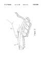
- FIG. 1is a perspective view of a remote control device constructed in accordance with an embodiment of the present invention.
- FIG. 2is a side view of the remote control device of FIG. 1.
- FIG. 3depicts the remote control device of FIG. 1 being operated by a user.
- FIG. 4is a top view of the remote control device of FIG. 1, with an exemplary layout of control buttons.
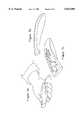
- FIGS. 5a-5cdepict different views of another embodiment of the present invention.
- FIGS. 6a-6cdepict different views of another embodiment of the present invention.
- FIGS. 7a-7ddepict different views of another embodiment of the present invention.
- FIGS. 8a-8cdepict different views of another embodiment of the present invention.
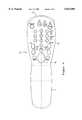
- FIG. 9is a perspective cut-away view of a portion of a remote control device constructed in accordance with an embodiment of the present invention.
- FIG. 10is a schematic depiction of a portion of the switch circuitry constructed in accordance with an embodiment of the present invention for controlling an awake/sleep mode of a microprocessor.
- FIG. 1is a perspective view of an embodiment of the present invention, but with only one button depicted for clarity of illustration of the shape of the remote control device 10.
- the remote control device 10has a communication section 12, which is normally pointed at the controlled device (not depicted).
- the remote control device 10is held at the grip end 14, which may also contain the batteries that supply power to the remote control device 10.
- the remote control device 10in certain embodiments, has a conductive plate 20 on the bottom of the grip 14 that acts with a control button 16 to close a circuit which controls whether certain circuitry in the remote control device is in an awake mode or a sleep mode.
- a conductive plate 20 on the bottom of the grip 14that acts with a control button 16 to close a circuit which controls whether certain circuitry in the remote control device is in an awake mode or a sleep mode.
- this arrangementprovides a great savings in power consumption by the remote control device 10 since circuitry that consumes a large amount of power will be in an awake mode (high power consumption mode) only when actually needed by the user.
- the button 16does not form part of the switch circuit, and other conductive areas on the grip 14 are provided, such as on the top part of the grip 14, to control the awake/sleep mode of the power consuming circuitry.
- Other types of switches activated in response to picking up and holding the remote control deviceare also contemplated.
- buttonsare provided in a control button area 18.
- An exemplary layout of buttonsis depicted in the top view of FIG. 4. It should be apparent that the invention is not limited to the use of control "buttons” per se, but also includes other types of actuation mechanisms, such as touch sensitive pads, rocker switches, etc.
- FIG. 2is a side view of the remote control device 10 of FIG. 1.
- the communication section 12which will be pointed at the controlled device, is angled with respect to the grip section 14 of the remote control device 10 by an angle A.
- This anglingallows the remote control device to be held and operated by a user in a natural "handshake" position that is normally assumed by a person extending their hand forward.
- the anglemay range from approximately 9 degrees to approximately 18 degrees, with an exemplary preferred angle of 12.5 degrees, to provide an angling that allows comfortable handling and operation of the remote control device 10. Other angles are possible, however, and fall within the spirit and scope of the present invention.
- FIG. 3depicts the remote control device 10 being held and operated by a user hand 22 that is in a natural handshake position.
- FIGS. 5a-5cdepict different views of another embodiment of the present invention that provides the user with a remote control device that can be held and operated in a natural fashion.
- FIGS. 6a-6cdepict different views of still another embodiment of the present invention.
- This embodimenthas a flip-up control button section cover that covers the control buttons when the remote control device is not in use.
- FIGS. 7a-7ddepict different views of a further embodiment of the present invention.
- This embodimenthas a flip-up control section cover that covers the control buttons when the remote control device is not in use.
- FIGS. 8a-8cdepict different views of a still further embodiment of the present invention in which the communication section is angled at nearly 90 degrees with respect to the grip end.
- FIG. 9is a perspective partially cut-away view of a remote control device constructed in accordance with an embodiment of the present invention.
- the top plate of the remote control device 10is not depicted so as to illustrate the components of the remote control device 10 that control the mode of the large power consuming circuitry.
- the large power consuming circuitryis a microprocessor that can be switched between an awake mode and a sleep mode.
- Such microprocessorsare well known.
- the inventionis not limited to use with microprocessors, but also finds utility in remote control devices that contain other types of large power consumption devices.
- the conductive plate 20is made of a conductive plastic.
- the use of conductive plasticis advantageous over metal as it is typically lighter in weight and less thermally conductive, as well as making fabrication easier. A user will therefore not pick up the remote control device 10 and feel either a warm metal or a cold metal plate. The lighter weight also reduces the possibility of hand and arm fatigue.
- the conductive plate 20also forms a door for the battery compartment.
- the remote control device 10houses a printed circuit board (PCB) 30 that carries the circuitry that performs the remotely controlling functionality of the remote control device 10.
- the PCB 30may be a conventional remote control PCB, or may be a customized PCB, depending on the applications desired for the remote control device 10.
- a microprocessor(not depicted in FIG. 9) is mounted on the PCB 30.
- the PCB 30(as well as the microprocessor on the PCB 30) are connected through a conductive ground wire 32.
- the other end of the conductive ground wire 32is connected to a metal ground bracket 34 located within the grip end 14 of the remote control device 10. This contact bracket 34 will be covered by the top plate of the grip end 14 when the remote control device is fully assembled.
- a downwardly extending portion 36 of the contact bracket 34contacts a metal spring 38 that is mounted in the conductive plate 20.
- the PCB 30is connected to the battery power supply through two wire form springs.
- a conductive plastic button 16is electrically connected to a metal button spring 42.
- the user's handUpon picking up the remote control device 10, the user's hand will contact the conductive plate 20 on the bottom of the grip 14.
- the remote control device 10When operating the remote control device 10 as an air mouse, the user's hand will also contact the conductive plastic button 16. This action completes a circuit path through the user's hand to electrically connect the conductive button 16 and the conductive plate 20.
- the microprocessoris controlled to switch from its sleep state to its awake state. When the microprocessor is in its awake state, which is a relatively high power consumption state, the remote control device 10 can be used as an air mouse, with the usual point and click functions associated with a mouse.
- FIG. 10A schematic depiction of an exemplary embodiment of the arrangement of the components used to control the awake/sleep state of the microprocessor are depicted in FIG. 10, and are generally provided with reference numeral 44, and the batteries have reference numeral 46. The remaining components are already depicted in FIG. 9 and have the same reference numerals as in that Figure.
- the voltage at the SW inputdrops to a low level. This places the microprocessor into the sleep mode or state, with a characteristically low power consumption. Since the battery power is not being consumed unless the users hand is actually properly holding the remote control device 10 as an air mouse, the batteries will need to be replaced less frequently.
- switch circuitry that controls the awake/sleep mode of the microprocessordoes not impact the operation of the other remote controlling functions, which are operable as in conventional remote control devices.
Landscapes
- Engineering & Computer Science (AREA)
- Multimedia (AREA)
- Signal Processing (AREA)
- Selective Calling Equipment (AREA)
Abstract
Description
The present invention relates to the field of control devices, and more particularly, to hand-held control devices for remotely operating a controlled device, such as a TV, computer (PC), VCR or digital satellite system.
Conventional remote control devices, used to operate televisions, VCRs and the like, are relatively linear in design. The remote control normally needs to be pointed at the stationary device to be controlled in order to communicate with the stationary device. The linear design of a conventional remote control forces the hand and wrist of the user into an awkward position in order to accurately point the remote control and at the same time operate the buttons on the remote control.
This problem will become even more noticeable as interactive multimedia becomes more prevalent, due to the amount of controlling that a user will perform with the remote control. For example, the remote control can be used as an "air mouse", or click and point device, in conjunction with a PC, VCR or a digital satellite system with on-screen program guides. It is expected that using the remote control in an awkward position for extended periods of time may lead to fatigue and more serious medical problems, such as carpal tunnel syndrome.
Another problem with current remote control devices arises when they are used as an air mouse. This problem is the relatively large power requirements of a microprocessor in the devices, which provides the remote control devices with the air mouse functionality. Maintaining the microprocessor in a state of readiness requires a large power consumption, causing frequent battery replacement. This is not usually a problem in conventional remote control devices in which the actuation of a button, such as a volume control, causes the current to flow from the battery power supply and activate the circuitry on the printed circuit board. However, with the advent of air mouse technology and the attendant use of power-hungry microprocessors, the power drain on the batteries will necessitate their frequent replacement in remote control devices. This is both expensive and annoying to the user.
There is a need for a remote control device that provides a more natural design that enables a user to point and operate the remote control device with a reduced amount of strain. There is also a need for a remote control device that has a reduced battery drain when the remote control device contains relatively large power consumption devices.
These and other needs are met by the present invention which provides a remote control device that has its communication section, which is pointed at a controlled device, angled with respect to the gripping area of the remote control device. This angling allows the remote control device to be held and operated by a user in a natural "handshake" position that is normally assumed by a person extending their hand forward. Since the remote control device is designed to be operated while the hand is in a naturally assumed position, the remote control device of the present invention can be operated for longer periods of time with reduced fatigue and strain.
The earlier stated needs are also met by another embodiment of the present invention, which provides a remote control device containing a large power consumption circuit, in which power is conserved through the use of conductive outer surfaces that form a switch that controls an awake/sleep state of the power consumer. The holding of the remote control device in the hand of a user with a finger (or thumb) on a button places the power consumer (such as a microprocessor) in an active or awake state. Conversely, in certain embodiments, the power consumer enters the sleep mode once the user hand is removed from its operating position on the remote control device.
One of the advantages of these embodiments of the present invention is the reduction in power drain, and therefore battery replacement, when the remote control device contains circuitry, such as a microprocessor, that consumes large amounts of power.
The foregoing and other features, aspects and advantages of the present invention will become more apparent from the following detailed description of the present invention when taken in conjunction with the accompanying drawings.
FIG. 1 is a perspective view of a remote control device constructed in accordance with an embodiment of the present invention.
FIG. 2 is a side view of the remote control device of FIG. 1.
FIG. 3 depicts the remote control device of FIG. 1 being operated by a user.
FIG. 4 is a top view of the remote control device of FIG. 1, with an exemplary layout of control buttons.
FIGS. 5a-5c depict different views of another embodiment of the present invention.
FIGS. 6a-6c depict different views of another embodiment of the present invention.
FIGS. 7a-7d depict different views of another embodiment of the present invention.
FIGS. 8a-8c depict different views of another embodiment of the present invention.
FIG. 9 is a perspective cut-away view of a portion of a remote control device constructed in accordance with an embodiment of the present invention.
FIG. 10 is a schematic depiction of a portion of the switch circuitry constructed in accordance with an embodiment of the present invention for controlling an awake/sleep mode of a microprocessor.
FIG. 1 is a perspective view of an embodiment of the present invention, but with only one button depicted for clarity of illustration of the shape of theremote control device 10. Theremote control device 10 has acommunication section 12, which is normally pointed at the controlled device (not depicted). Theremote control device 10 is held at thegrip end 14, which may also contain the batteries that supply power to theremote control device 10.
Theremote control device 10, in certain embodiments, has aconductive plate 20 on the bottom of thegrip 14 that acts with acontrol button 16 to close a circuit which controls whether certain circuitry in the remote control device is in an awake mode or a sleep mode. As described in more detail later with respect to FIG. 9, this arrangement provides a great savings in power consumption by theremote control device 10 since circuitry that consumes a large amount of power will be in an awake mode (high power consumption mode) only when actually needed by the user.
In certain embodiments, not shown, thebutton 16 does not form part of the switch circuit, and other conductive areas on thegrip 14 are provided, such as on the top part of thegrip 14, to control the awake/sleep mode of the power consuming circuitry. Other types of switches activated in response to picking up and holding the remote control device are also contemplated.
The remote control buttons are provided in acontrol button area 18. An exemplary layout of buttons is depicted in the top view of FIG. 4. It should be apparent that the invention is not limited to the use of control "buttons" per se, but also includes other types of actuation mechanisms, such as touch sensitive pads, rocker switches, etc.
FIG. 2 is a side view of theremote control device 10 of FIG. 1. As is apparent from FIG. 2, thecommunication section 12, which will be pointed at the controlled device, is angled with respect to thegrip section 14 of theremote control device 10 by an angle A. This angling allows the remote control device to be held and operated by a user in a natural "handshake" position that is normally assumed by a person extending their hand forward. The angle may range from approximately 9 degrees to approximately 18 degrees, with an exemplary preferred angle of 12.5 degrees, to provide an angling that allows comfortable handling and operation of theremote control device 10. Other angles are possible, however, and fall within the spirit and scope of the present invention.
FIG. 3 depicts theremote control device 10 being held and operated by auser hand 22 that is in a natural handshake position.
FIGS. 5a-5c depict different views of another embodiment of the present invention that provides the user with a remote control device that can be held and operated in a natural fashion.
FIGS. 6a-6c depict different views of still another embodiment of the present invention. This embodiment has a flip-up control button section cover that covers the control buttons when the remote control device is not in use.
FIGS. 7a-7d depict different views of a further embodiment of the present invention. This embodiment has a flip-up control section cover that covers the control buttons when the remote control device is not in use.
FIGS. 8a-8c depict different views of a still further embodiment of the present invention in which the communication section is angled at nearly 90 degrees with respect to the grip end.
FIG. 9 is a perspective partially cut-away view of a remote control device constructed in accordance with an embodiment of the present invention. In this view, the top plate of theremote control device 10 is not depicted so as to illustrate the components of theremote control device 10 that control the mode of the large power consuming circuitry. In the following exemplary embodiment, the large power consuming circuitry is a microprocessor that can be switched between an awake mode and a sleep mode. Such microprocessors are well known. The invention is not limited to use with microprocessors, but also finds utility in remote control devices that contain other types of large power consumption devices.
In the embodiment of FIG. 9, theconductive plate 20 is made of a conductive plastic. The use of conductive plastic is advantageous over metal as it is typically lighter in weight and less thermally conductive, as well as making fabrication easier. A user will therefore not pick up theremote control device 10 and feel either a warm metal or a cold metal plate. The lighter weight also reduces the possibility of hand and arm fatigue. In certain preferred embodiments of the present invention, theconductive plate 20 also forms a door for the battery compartment.
Theremote control device 10 houses a printed circuit board (PCB) 30 that carries the circuitry that performs the remotely controlling functionality of theremote control device 10. ThePCB 30 may be a conventional remote control PCB, or may be a customized PCB, depending on the applications desired for theremote control device 10. In the exemplary embodiment of theremote control device 10 of the present invention, a microprocessor (not depicted in FIG. 9) is mounted on thePCB 30.
The PCB 30 (as well as the microprocessor on the PCB 30) are connected through aconductive ground wire 32. The other end of theconductive ground wire 32 is connected to ametal ground bracket 34 located within the grip end 14 of theremote control device 10. Thiscontact bracket 34 will be covered by the top plate of thegrip end 14 when the remote control device is fully assembled. A downwardly extendingportion 36 of thecontact bracket 34 contacts ametal spring 38 that is mounted in theconductive plate 20.
ThePCB 30 is connected to the battery power supply through two wire form springs. Aconductive plastic button 16 is electrically connected to ametal button spring 42. Upon picking up theremote control device 10, the user's hand will contact theconductive plate 20 on the bottom of thegrip 14. When operating theremote control device 10 as an air mouse, the user's hand will also contact theconductive plastic button 16. This action completes a circuit path through the user's hand to electrically connect theconductive button 16 and theconductive plate 20. Once the circuit path is completed, the microprocessor is controlled to switch from its sleep state to its awake state. When the microprocessor is in its awake state, which is a relatively high power consumption state, theremote control device 10 can be used as an air mouse, with the usual point and click functions associated with a mouse.
A schematic depiction of an exemplary embodiment of the arrangement of the components used to control the awake/sleep state of the microprocessor are depicted in FIG. 10, and are generally provided with reference numeral 44, and the batteries havereference numeral 46. The remaining components are already depicted in FIG. 9 and have the same reference numerals as in that Figure.
When the user releases thecontrol button 16 or theremote control device 10, the voltage at the SW input (the awake/sleep control input) drops to a low level. This places the microprocessor into the sleep mode or state, with a characteristically low power consumption. Since the battery power is not being consumed unless the users hand is actually properly holding theremote control device 10 as an air mouse, the batteries will need to be replaced less frequently.
It is to be noted that the switch circuitry that controls the awake/sleep mode of the microprocessor does not impact the operation of the other remote controlling functions, which are operable as in conventional remote control devices.
Although the present invention has been described and illustrated in detail, it is to be clearly understood that the same is by way of illustration and example only and is not to be taken by way of limitation, the spirit and scope of the present invention being limited only by the terms of the appended claims.
Claims (18)
1. A remote control device for controlling a controllable device, comprising:
high power consuming circuitry controllable to enter either a relatively low power sleep mode or a relatively high power awake mode;
an actuation mechanism operable by a user to control the high power consuming circuitry to perform a remote controlling of the controllable device;
a conductive plate that contacts the user hand when the remote control device is held in the user hand; and
a switch circuit that causes the high power consuming circuitry to transition between the relatively lower power sleep mode and the relatively high power awake mode, in response to the user holding the remote control device and simultaneously contacting the conductive plate and the actuation mechanism, wherein the relatively high power awake mode enables the remote controlling of the controllable device.
2. The remote control device of claim 1, wherein the actuation mechanism is a control button.
3. The remote control device of claim 1, further including a grip portion for holding of the remote control device in the hand of the user.
4. The remote control device of claim 3, wherein the grip portion includes the conductive plate that contacts the user hand when the remote control device is held in the user hand, the conductive plate forming part of the switch circuit.
5. The remote control device of claim 4, wherein the actuation mechanism forms part of the switch circuit.
6. The remote control device of claim 5, wherein the actuation mechanism is made of conductive material and is a button.
7. The remote control device of claim 6, wherein the conductive material is a plastic.
8. The remote control device of claim 4, wherein the conductive plate is made of plastic.
9. The remote control device of claim 8, wherein the conductive plate is a battery door of the remote control device.
10. The remote control device of claim 6, wherein the high power consuming circuitry includes a microprocessor.
11. An air mouse for pointing and clicking at a controllable device to control the controllable device, the air mouse comprising:
a microprocessor controllable to enter either a relatively low power sleep mode or a relatively high power awake mode;
an actuation mechanism operable by a user to control the microprocessor to perform a remote controlling of the controllable device;
a conductive plate that contacts the user hand when the remote control device is held in the user hand; and
a switch circuit that causes the microprocessor to transition between the relatively lower power sleep mode and the relatively high power awake mode, in response to the user holding the air mouse and simultaneously contacting the conductive plate and the actuation mechanism, wherein the relatively high power awake mode enables the remote controlling of the controllable device.
12. The air mouse of claim 11, further including a grip portion for holding of the air mouse in the hand of the user.
13. The air mouse of claim 12, wherein the grip portion includes the conductive plate that contacts the user hand when the air mouse is held in the user hand, the conductive plate forming part of the switch circuit.
14. The air mouse of claim 13, wherein the actuation mechanism forms part of the switch circuit.
15. The air mouse of claim 14, wherein the actuation mechanism is made of conductive material and is a button.
16. The air mouse of claim 15, wherein the conductive material is a plastic.
17. The air mouse of claim 13, wherein the conductive plate is made of plastic.
18. The air mouse of claim 17, wherein the conductive plate is a battery door of the air mouse.
Priority Applications (1)
| Application Number | Priority Date | Filing Date | Title |
|---|---|---|---|
| US08/699,028US5812085A (en) | 1996-08-15 | 1996-08-15 | Remote control device |
Applications Claiming Priority (1)
| Application Number | Priority Date | Filing Date | Title |
|---|---|---|---|
| US08/699,028US5812085A (en) | 1996-08-15 | 1996-08-15 | Remote control device |
Publications (1)
| Publication Number | Publication Date |
|---|---|
| US5812085Atrue US5812085A (en) | 1998-09-22 |
Family
ID=24807640
Family Applications (1)
| Application Number | Title | Priority Date | Filing Date |
|---|---|---|---|
| US08/699,028Expired - LifetimeUS5812085A (en) | 1996-08-15 | 1996-08-15 | Remote control device |
Country Status (1)
| Country | Link |
|---|---|
| US (1) | US5812085A (en) |
Cited By (25)
| Publication number | Priority date | Publication date | Assignee | Title |
|---|---|---|---|---|
| US6035350A (en)* | 1997-01-21 | 2000-03-07 | Dell Usa, L.P. | Detachable I/O device with built-in RF/IR functionality to facilitate remote audio-visual presentation |
| US20010043191A1 (en)* | 1997-07-31 | 2001-11-22 | Todd D. Lindsey | Audio and video controls on a pointing device for a computer |
| DE19939365C2 (en)* | 1999-08-19 | 2002-10-24 | Siemens Ag | Method and arrangement for identifying a mobile station belonging to a base station |
| US6618580B2 (en) | 2000-02-14 | 2003-09-09 | Intel Corporation | Apparatus and method for remotely powering-down a wireless transceiver |
| USD481685S1 (en) | 2002-03-13 | 2003-11-04 | Hästens Sängar AB | Remote control unit |
| USD481686S1 (en) | 2002-03-13 | 2003-11-04 | Hästens Sängar AB | Remote control unit |
| US20040075694A1 (en)* | 1999-06-08 | 2004-04-22 | Amx Corporation | System and method for multimedia display |
| US20050104742A1 (en)* | 2003-11-13 | 2005-05-19 | James Phifer | Ergonomic television remote control |
| US20050104853A1 (en)* | 2003-11-13 | 2005-05-19 | Chatree Sitalasai | Mechanical motion sensor and low-power trigger circuit |
| US20050149363A1 (en)* | 2004-01-07 | 2005-07-07 | Jonathan Loiterman | Data collection and process control system |
| US20050270735A1 (en)* | 2004-06-07 | 2005-12-08 | Che-Chih Chen | Remote control holding unit |
| US20060021860A1 (en)* | 2003-01-31 | 2006-02-02 | Neeco-Tron, Inc. | Control housing and method of manufacturing same |
| USD531993S1 (en) | 2005-12-02 | 2006-11-14 | Samsung Electronics Co., Ltd. | Remote controller |
| US20070054651A1 (en)* | 2005-09-07 | 2007-03-08 | Amx, Llc | Power management for electronic devices |
| US7213061B1 (en) | 1999-04-29 | 2007-05-01 | Amx Llc | Internet control system and method |
| US7224366B2 (en) | 2002-10-17 | 2007-05-29 | Amx, Llc | Method and system for control system software |
| USD551632S1 (en) | 2006-04-26 | 2007-09-25 | Samsung Electronics Co., Ltd. | Wireless remote controller for computer |
| US20090228695A1 (en)* | 2008-03-04 | 2009-09-10 | Rabindra Pathak | Remote wakeup web service for imaging device |
| CN101763181B (en)* | 2008-12-24 | 2012-04-18 | 索尼株式会社 | Input apparatus, control apparatus, and control method for input apparatus |
| CN103197771A (en)* | 2013-04-07 | 2013-07-10 | 广州视睿电子科技有限公司 | Television and computer integrated machine and method for remotely controlling external computer |
| US20140125463A1 (en)* | 2011-05-13 | 2014-05-08 | Lutron Electronics Co., Inc. | Control device having a night light |
| US8806229B1 (en) | 2008-09-29 | 2014-08-12 | Cypress Semiconductor Corporation | Power reduction circuits and methods |
| CN104182035A (en)* | 2013-05-28 | 2014-12-03 | 中国电信股份有限公司 | Method and system for controlling television application program |
| US9063739B2 (en) | 2005-09-07 | 2015-06-23 | Open Invention Network, Llc | Method and computer program for device configuration |
| CN113259735A (en)* | 2020-02-10 | 2021-08-13 | 深圳Tcl数字技术有限公司 | Remote controller awakening method, remote controller and storage medium |
Citations (12)
| Publication number | Priority date | Publication date | Assignee | Title |
|---|---|---|---|---|
| USD266758S (en) | 1980-03-24 | 1982-11-02 | Technicare Corporation | Hand-held control module for an ultrasound diagnostic imaging system |
| US4380121A (en)* | 1980-04-03 | 1983-04-19 | Payer-Lux Elektroprodukte Gesellschaft M.B.H. | Electric shaver |
| US4969508A (en)* | 1990-01-25 | 1990-11-13 | United Enertech Corporation | Wireless thermostat and room environment control system |
| USD337588S (en) | 1991-08-12 | 1993-07-20 | Voice Powered Technology International, Inc. | Hand held voice actuated control apparatus |
| US5381142A (en)* | 1993-02-19 | 1995-01-10 | Thomson Consumer Electronics, Inc. | Remote control unit having additional keys serviced via an interrupt |
| USD356570S (en) | 1993-01-08 | 1995-03-21 | Matsushita Electric Industrial Co., Ltd. | Remote controller for video tape recorder |
| USD363486S (en) | 1994-01-14 | 1995-10-24 | Matsushita Electric Industrial Co., Ltd. | Remote controller for video tape recorder |
| USD372245S (en) | 1995-04-03 | 1996-07-30 | At&T Corp. | Hand-held remote control unit |
| US5545857A (en)* | 1994-07-27 | 1996-08-13 | Samsung Electronics Co. Ltd. | Remote control method and apparatus thereof |
| USD377023S (en) | 1995-06-05 | 1996-12-31 | Andrea Electronics Corportion | Untethered communications/media handset |
| USD377797S (en) | 1995-09-27 | 1997-02-04 | Video Guide, Inc. | Remote control device for electronic equipment |
| US5657091A (en)* | 1995-11-01 | 1997-08-12 | International Business Machines Corporation | Video display controller, user interface and programming structure for such interface |
- 1996
- 1996-08-15USUS08/699,028patent/US5812085A/ennot_activeExpired - Lifetime
Patent Citations (12)
| Publication number | Priority date | Publication date | Assignee | Title |
|---|---|---|---|---|
| USD266758S (en) | 1980-03-24 | 1982-11-02 | Technicare Corporation | Hand-held control module for an ultrasound diagnostic imaging system |
| US4380121A (en)* | 1980-04-03 | 1983-04-19 | Payer-Lux Elektroprodukte Gesellschaft M.B.H. | Electric shaver |
| US4969508A (en)* | 1990-01-25 | 1990-11-13 | United Enertech Corporation | Wireless thermostat and room environment control system |
| USD337588S (en) | 1991-08-12 | 1993-07-20 | Voice Powered Technology International, Inc. | Hand held voice actuated control apparatus |
| USD356570S (en) | 1993-01-08 | 1995-03-21 | Matsushita Electric Industrial Co., Ltd. | Remote controller for video tape recorder |
| US5381142A (en)* | 1993-02-19 | 1995-01-10 | Thomson Consumer Electronics, Inc. | Remote control unit having additional keys serviced via an interrupt |
| USD363486S (en) | 1994-01-14 | 1995-10-24 | Matsushita Electric Industrial Co., Ltd. | Remote controller for video tape recorder |
| US5545857A (en)* | 1994-07-27 | 1996-08-13 | Samsung Electronics Co. Ltd. | Remote control method and apparatus thereof |
| USD372245S (en) | 1995-04-03 | 1996-07-30 | At&T Corp. | Hand-held remote control unit |
| USD377023S (en) | 1995-06-05 | 1996-12-31 | Andrea Electronics Corportion | Untethered communications/media handset |
| USD377797S (en) | 1995-09-27 | 1997-02-04 | Video Guide, Inc. | Remote control device for electronic equipment |
| US5657091A (en)* | 1995-11-01 | 1997-08-12 | International Business Machines Corporation | Video display controller, user interface and programming structure for such interface |
Cited By (34)
| Publication number | Priority date | Publication date | Assignee | Title |
|---|---|---|---|---|
| US6035350A (en)* | 1997-01-21 | 2000-03-07 | Dell Usa, L.P. | Detachable I/O device with built-in RF/IR functionality to facilitate remote audio-visual presentation |
| US20010043191A1 (en)* | 1997-07-31 | 2001-11-22 | Todd D. Lindsey | Audio and video controls on a pointing device for a computer |
| US7213061B1 (en) | 1999-04-29 | 2007-05-01 | Amx Llc | Internet control system and method |
| US8572224B2 (en) | 1999-04-29 | 2013-10-29 | Thomas D. Hite | Internet control system communication protocol, method and computer program |
| US7673030B2 (en) | 1999-04-29 | 2010-03-02 | Amx Llc | Internet control system communication protocol, method and computer program |
| US7426702B2 (en) | 1999-06-08 | 2008-09-16 | Amx Llc | System and method for multimedia display |
| US20040075694A1 (en)* | 1999-06-08 | 2004-04-22 | Amx Corporation | System and method for multimedia display |
| DE19939365C2 (en)* | 1999-08-19 | 2002-10-24 | Siemens Ag | Method and arrangement for identifying a mobile station belonging to a base station |
| US6754513B1 (en) | 1999-08-19 | 2004-06-22 | Siemens Aktiengesellschaft | Method and configuration for identification of a mobile station associated with a base station |
| US6618580B2 (en) | 2000-02-14 | 2003-09-09 | Intel Corporation | Apparatus and method for remotely powering-down a wireless transceiver |
| USD481686S1 (en) | 2002-03-13 | 2003-11-04 | Hästens Sängar AB | Remote control unit |
| USD481685S1 (en) | 2002-03-13 | 2003-11-04 | Hästens Sängar AB | Remote control unit |
| US7224366B2 (en) | 2002-10-17 | 2007-05-29 | Amx, Llc | Method and system for control system software |
| US20060021860A1 (en)* | 2003-01-31 | 2006-02-02 | Neeco-Tron, Inc. | Control housing and method of manufacturing same |
| US7146701B2 (en)* | 2003-01-31 | 2006-12-12 | Neeco-Tron, Inc. | Control housing and method of manufacturing same |
| US7170420B2 (en) | 2003-11-13 | 2007-01-30 | James Phifer | Ergonomic television remote control |
| US20050104853A1 (en)* | 2003-11-13 | 2005-05-19 | Chatree Sitalasai | Mechanical motion sensor and low-power trigger circuit |
| US20050104742A1 (en)* | 2003-11-13 | 2005-05-19 | James Phifer | Ergonomic television remote control |
| US20050149363A1 (en)* | 2004-01-07 | 2005-07-07 | Jonathan Loiterman | Data collection and process control system |
| US20050270735A1 (en)* | 2004-06-07 | 2005-12-08 | Che-Chih Chen | Remote control holding unit |
| US20070054651A1 (en)* | 2005-09-07 | 2007-03-08 | Amx, Llc | Power management for electronic devices |
| US7786623B2 (en) | 2005-09-07 | 2010-08-31 | Amx Llc | Power management for electronic devices |
| US9063739B2 (en) | 2005-09-07 | 2015-06-23 | Open Invention Network, Llc | Method and computer program for device configuration |
| USD531993S1 (en) | 2005-12-02 | 2006-11-14 | Samsung Electronics Co., Ltd. | Remote controller |
| USD551632S1 (en) | 2006-04-26 | 2007-09-25 | Samsung Electronics Co., Ltd. | Wireless remote controller for computer |
| US8001404B2 (en) | 2008-03-04 | 2011-08-16 | Sharp Laboratories Of America, Inc. | Remote wakeup web service for imaging device |
| US20090228695A1 (en)* | 2008-03-04 | 2009-09-10 | Rabindra Pathak | Remote wakeup web service for imaging device |
| US8806229B1 (en) | 2008-09-29 | 2014-08-12 | Cypress Semiconductor Corporation | Power reduction circuits and methods |
| CN101763181B (en)* | 2008-12-24 | 2012-04-18 | 索尼株式会社 | Input apparatus, control apparatus, and control method for input apparatus |
| US20140125463A1 (en)* | 2011-05-13 | 2014-05-08 | Lutron Electronics Co., Inc. | Control device having a night light |
| CN103197771A (en)* | 2013-04-07 | 2013-07-10 | 广州视睿电子科技有限公司 | Television and computer integrated machine and method for remotely controlling external computer |
| CN103197771B (en)* | 2013-04-07 | 2016-04-27 | 广州视睿电子科技有限公司 | Television and computer integrated machine and method for remotely controlling external computer |
| CN104182035A (en)* | 2013-05-28 | 2014-12-03 | 中国电信股份有限公司 | Method and system for controlling television application program |
| CN113259735A (en)* | 2020-02-10 | 2021-08-13 | 深圳Tcl数字技术有限公司 | Remote controller awakening method, remote controller and storage medium |
Similar Documents
| Publication | Publication Date | Title |
|---|---|---|
| US5812085A (en) | Remote control device | |
| US5670988A (en) | Trigger operated electronic device | |
| US5287090A (en) | Combination mouse and track ball unit | |
| US5648798A (en) | Universal ergonomic computer mouse/trackball | |
| US6496181B1 (en) | Scroll select-activate button for wireless terminals | |
| US5973757A (en) | Contoured and balanced remote tv control device | |
| US7333086B2 (en) | Dual mode computer mouse | |
| US6545667B1 (en) | Apparatus for a convenient and comfortable cursor control device | |
| US20080259028A1 (en) | Hand glove mouse | |
| US20050159850A1 (en) | Shift knob computer operating device | |
| US20060139331A1 (en) | Ergonomic computer mouse | |
| JP2004534316A (en) | Gloves computer mouse | |
| US6201534B1 (en) | Trackball for single digit control of wireless terminal | |
| US20080225004A1 (en) | Wireless mouse | |
| US20070268250A1 (en) | Remote input device for computers | |
| EP0824279B1 (en) | Remote controller | |
| US20030227437A1 (en) | Computer pointing device and utilization system | |
| US7463242B2 (en) | Stationary ergonomic mouse | |
| CA2457929A1 (en) | Intelligent line switch | |
| US7085130B2 (en) | Electronic device and button structure | |
| CN212379967U (en) | A one-hand switching remote control | |
| JP4262735B2 (en) | PC peripherals | |
| CN215274355U (en) | Neck massager and wearing bracket thereof | |
| US12253245B1 (en) | Lighting device with low mispress buttons | |
| WO2002052391A2 (en) | Manually operable remote controller |
Legal Events
| Date | Code | Title | Description |
|---|---|---|---|
| AS | Assignment | Owner name:SAMSUNG INFORMATION SYSTEMS AMERICA, CALIFORNIA Free format text:ASSIGNMENT OF ASSIGNORS INTEREST;ASSIGNORS:BARRAZA, STEVEN E.;KNAPP, WILLIAM R.;SUMMIT, SCOTT;REEL/FRAME:008288/0336 Effective date:19960815 | |
| STCF | Information on status: patent grant | Free format text:PATENTED CASE | |
| AS | Assignment | Owner name:SAMSUNG ELECTRONICS CO., LTD., KOREA, REPUBLIC OF Free format text:ASSIGNMENT OF ASSIGNORS INTEREST;ASSIGNOR:SAMSUNG INFORMATION SYSTEMS AMERICA;REEL/FRAME:010129/0130 Effective date:19990701 | |
| FEPP | Fee payment procedure | Free format text:PAYOR NUMBER ASSIGNED (ORIGINAL EVENT CODE: ASPN); ENTITY STATUS OF PATENT OWNER: LARGE ENTITY | |
| FPAY | Fee payment | Year of fee payment:4 | |
| FPAY | Fee payment | Year of fee payment:8 | |
| FPAY | Fee payment | Year of fee payment:12 |