US5810868A - Stent for improved transluminal deployment - Google Patents
Stent for improved transluminal deploymentDownload PDFInfo
- Publication number
- US5810868A US5810868AUS08/568,834US56883495AUS5810868AUS 5810868 AUS5810868 AUS 5810868AUS 56883495 AUS56883495 AUS 56883495AUS 5810868 AUS5810868 AUS 5810868A
- Authority
- US
- United States
- Prior art keywords
- stent
- apex
- radiused
- bulbous portion
- profile
- Prior art date
- Legal status (The legal status is an assumption and is not a legal conclusion. Google has not performed a legal analysis and makes no representation as to the accuracy of the status listed.)
- Expired - Lifetime
Links
Images


Classifications
- A—HUMAN NECESSITIES
- A61—MEDICAL OR VETERINARY SCIENCE; HYGIENE
- A61F—FILTERS IMPLANTABLE INTO BLOOD VESSELS; PROSTHESES; DEVICES PROVIDING PATENCY TO, OR PREVENTING COLLAPSING OF, TUBULAR STRUCTURES OF THE BODY, e.g. STENTS; ORTHOPAEDIC, NURSING OR CONTRACEPTIVE DEVICES; FOMENTATION; TREATMENT OR PROTECTION OF EYES OR EARS; BANDAGES, DRESSINGS OR ABSORBENT PADS; FIRST-AID KITS
- A61F2/00—Filters implantable into blood vessels; Prostheses, i.e. artificial substitutes or replacements for parts of the body; Appliances for connecting them with the body; Devices providing patency to, or preventing collapsing of, tubular structures of the body, e.g. stents
- A61F2/82—Devices providing patency to, or preventing collapsing of, tubular structures of the body, e.g. stents
- A61F2/86—Stents in a form characterised by the wire-like elements; Stents in the form characterised by a net-like or mesh-like structure
- A61F2/90—Stents in a form characterised by the wire-like elements; Stents in the form characterised by a net-like or mesh-like structure characterised by a net-like or mesh-like structure
- A61F2/91—Stents in a form characterised by the wire-like elements; Stents in the form characterised by a net-like or mesh-like structure characterised by a net-like or mesh-like structure made from perforated sheets or tubes, e.g. perforated by laser cuts or etched holes
- A61F2/915—Stents in a form characterised by the wire-like elements; Stents in the form characterised by a net-like or mesh-like structure characterised by a net-like or mesh-like structure made from perforated sheets or tubes, e.g. perforated by laser cuts or etched holes with bands having a meander structure, adjacent bands being connected to each other
- A—HUMAN NECESSITIES
- A61—MEDICAL OR VETERINARY SCIENCE; HYGIENE
- A61F—FILTERS IMPLANTABLE INTO BLOOD VESSELS; PROSTHESES; DEVICES PROVIDING PATENCY TO, OR PREVENTING COLLAPSING OF, TUBULAR STRUCTURES OF THE BODY, e.g. STENTS; ORTHOPAEDIC, NURSING OR CONTRACEPTIVE DEVICES; FOMENTATION; TREATMENT OR PROTECTION OF EYES OR EARS; BANDAGES, DRESSINGS OR ABSORBENT PADS; FIRST-AID KITS
- A61F2/00—Filters implantable into blood vessels; Prostheses, i.e. artificial substitutes or replacements for parts of the body; Appliances for connecting them with the body; Devices providing patency to, or preventing collapsing of, tubular structures of the body, e.g. stents
- A61F2/82—Devices providing patency to, or preventing collapsing of, tubular structures of the body, e.g. stents
- A61F2/86—Stents in a form characterised by the wire-like elements; Stents in the form characterised by a net-like or mesh-like structure
- A—HUMAN NECESSITIES
- A61—MEDICAL OR VETERINARY SCIENCE; HYGIENE
- A61F—FILTERS IMPLANTABLE INTO BLOOD VESSELS; PROSTHESES; DEVICES PROVIDING PATENCY TO, OR PREVENTING COLLAPSING OF, TUBULAR STRUCTURES OF THE BODY, e.g. STENTS; ORTHOPAEDIC, NURSING OR CONTRACEPTIVE DEVICES; FOMENTATION; TREATMENT OR PROTECTION OF EYES OR EARS; BANDAGES, DRESSINGS OR ABSORBENT PADS; FIRST-AID KITS
- A61F2/00—Filters implantable into blood vessels; Prostheses, i.e. artificial substitutes or replacements for parts of the body; Appliances for connecting them with the body; Devices providing patency to, or preventing collapsing of, tubular structures of the body, e.g. stents
- A61F2/82—Devices providing patency to, or preventing collapsing of, tubular structures of the body, e.g. stents
- A61F2/848—Devices providing patency to, or preventing collapsing of, tubular structures of the body, e.g. stents having means for fixation to the vessel wall, e.g. barbs
- A61F2002/8486—Devices providing patency to, or preventing collapsing of, tubular structures of the body, e.g. stents having means for fixation to the vessel wall, e.g. barbs provided on at least one of the ends
- A—HUMAN NECESSITIES
- A61—MEDICAL OR VETERINARY SCIENCE; HYGIENE
- A61F—FILTERS IMPLANTABLE INTO BLOOD VESSELS; PROSTHESES; DEVICES PROVIDING PATENCY TO, OR PREVENTING COLLAPSING OF, TUBULAR STRUCTURES OF THE BODY, e.g. STENTS; ORTHOPAEDIC, NURSING OR CONTRACEPTIVE DEVICES; FOMENTATION; TREATMENT OR PROTECTION OF EYES OR EARS; BANDAGES, DRESSINGS OR ABSORBENT PADS; FIRST-AID KITS
- A61F2/00—Filters implantable into blood vessels; Prostheses, i.e. artificial substitutes or replacements for parts of the body; Appliances for connecting them with the body; Devices providing patency to, or preventing collapsing of, tubular structures of the body, e.g. stents
- A61F2/82—Devices providing patency to, or preventing collapsing of, tubular structures of the body, e.g. stents
- A61F2/86—Stents in a form characterised by the wire-like elements; Stents in the form characterised by a net-like or mesh-like structure
- A61F2/90—Stents in a form characterised by the wire-like elements; Stents in the form characterised by a net-like or mesh-like structure characterised by a net-like or mesh-like structure
- A61F2/91—Stents in a form characterised by the wire-like elements; Stents in the form characterised by a net-like or mesh-like structure characterised by a net-like or mesh-like structure made from perforated sheets or tubes, e.g. perforated by laser cuts or etched holes
- A61F2/915—Stents in a form characterised by the wire-like elements; Stents in the form characterised by a net-like or mesh-like structure characterised by a net-like or mesh-like structure made from perforated sheets or tubes, e.g. perforated by laser cuts or etched holes with bands having a meander structure, adjacent bands being connected to each other
- A61F2002/9155—Adjacent bands being connected to each other
- A61F2002/91558—Adjacent bands being connected to each other connected peak to peak
Definitions
- This inventionrelates to medical implant devices. More specifically, the invention relates to an improved implantable stent apparatus for the treatment of stenoses in coronary or peripheral vessels in humans.
- angioplastypercutaneous transluminal coronary angioplasty
- the objective in angioplastyis to enlarge the lumen of the affected coronary artery by radial hydraulic expansion.
- the procedureis accomplished by inflating a balloon within the narrowed lumen of the coronary artery.
- Radial expansion of the coronary arteryoccurs in several different dimensions, and is related to the nature of the plaque. Soft, fatty plaque deposits are flattened by the balloon, while hardened deposits are cracked and split to enlarge the lumen.
- the wall of the artery itselfis also stretched when the balloon is inflated.
- U.S. Pat. No. 4,655,771 to Wallstendescribes a stent comprising a tube of stainless wire braid.
- the tubeis positioned along a delivery device, such as a catheter, in extended form, making the tube diameter as small as possible.
- a delivery devicesuch as a catheter
- the stentis positioned across the lesion, it is expanded, causing the length of the tube to contract and the diameter to expand.
- the tubemaintains the new shape either through mechanical force or otherwise.
- Stentsare typically delivered to affected areas of vessels using standard catheterization techniques.
- a thin walled hollow guiding catheteris introduced into the body via a relatively large vessel, such as the femoral artery in the groin area or the brachial artery in the arm by insertion through a hollow sheath.
- the guiding catheteris maneuvered through an approximately 180 degree turn through the aortic arch to descend into the aortic cusp where entry may be gained to either the left or the right coronary artery, as desired.
- the relatively rigid stentmay be dislodged from the more pliable balloon material of the flexible delivery device when contact occurs between the vessel wall and the stent, particularly during passage through a curve.
- the low mass of the rigid stents, and construction methods of some stentscauses the end portions to have small cross-sections and to be somewhat ridged and sharp.
- the small, sharp, cross-sections at the ends of the stentsincrease the risk that a stent will penetrate the vessel wall, particularly when the narrow, rigid end of a stent encounters a curve in a vessel.
- the flexible delivery device and balloon materialfollow the contours of the vessel, and when negotiating a curve, the distal end of the more rigid stent may separate slightly from the balloon and delivery device. The separated, sharp distal end may cause abrasion or penetrate the soft tissues of the vessel wall.
- a stent constructed in accordance with this inventionmay be in the form of an expandable, generally tubular body portion having two ends, wherein at least one end of the stent is provided with a generally rounded, smooth radius.
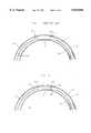
- FIG. 1is an elevational sectional view of an illustrative prior art stent attempting to negotiate a curve in a narrow vessel.
- FIG. 2is an elevational sectional view of an illustrative stent according to the present invention attempting to negotiate a curve in a narrow vessel.
- FIGS. 4A-4Bshow respectively, perspective and end views of an illustrative mesh stent constructed in accordance with the present invention and having bulbous portions created by bending the material of the stent wall at the apices of the stent outward.
- FIGS. 5A-5Bshow respectively, perspective and end views of an illustrative mesh stent constructed in accordance with the present invention and having bulbous portions created by providing extra material at the apices of the stent.
- FIG. 1is a diagrammatic side view of prior art stent 11 shown compressed on a delivery device, in this case on balloon 12 of balloon catheter 13.
- Stent 11is shown attempting to negotiate a curve while passing through the lumen of narrow vessel 14.
- Distal end 15 of substantially rigid stent 11separates from the pliable balloon material and flexible catheter 13 as catheter 13 and balloon 12 curve to follow the contour of the vessel 14. The separation is illustratively shown as gap 16.
- Distal end 15contacts intima 17 of vessel 14 because substantially rigid metallic stent 11 does not bend around the curve in the vessel wall as readily as flexible catheter 13 and pliable balloon 12.
- contact by distal end 15 of stent 11may cause abrasion to intima 17, or even dissection of vessel 14. More important, it may be impossible to deliver stent 11 to the desired location in vessel 14 if stent 11 cannot be maneuvered through the turn.
- a polymer materialmay also be formed around the apex of the stent in powdered or molten form.
- heat-shrink plastic elementsmay be inserted over portions of the stent and heat treated at the apex locations.
- a suitable biocompatible polymermay be chosen which forms a good bond with the vessel over time. This integration of the ends of the stent with the intima of the vessel wall is expected to have the additional benefit of anchoring the stent over time.
- the additional material at the apex of stent 51 in the region of apex 52may also be provided by thickening the stent.
- the apex of a stentsuch as stent 31 of FIG. 3A may be heated to form a bead of softened or molten stent material which forms the radius when cooled as, illustrated by stent 51 of FIG. 5A.
- the radius 53may then be polished if desired to eliminate any irregularities.
- the thicker stent materialadds radius 53 to apex 52 of stent 51.
- This additional thickness of the materialincreases the profile of apex 52 of stent 51 that is presented to the wall of the vessel as described hereinabove. It will be recognized by those skilled in the art that the increased thickness of material forming the radius at an apex of stent 51 also may be provided by using powder metallurgy techniques or selective machining.
- Stent 61 of FIG. 6illustrates an alternative embodiment of the present invention in which the apex of the stent is provided with a radius in the plane of the wall of the stent.
- the apices 62 of stent 61are rounded off at the edges 63. It is believed that while not necessarily increasing the thickness of stent 61 in the region of apices 62 of the stent, the radius provided by rounding the apices of the stent will improve trackability of the stent.
- the profile of the stentmay additionally be increased by forming another radius on the stent by adding material in the region of the apices 62 as shown in FIGS. 5A and 5B.
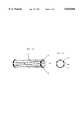
- the stent of FIGS. 7A-7Cis illustratively formed from a wire structure for example, like the stent described in Boneau U.S. Pat. No. 5,292,331.
- wire-type stentscan be manufactured either by bonding together separate elements into the desired configuration or by bending a unitary piece of wire-like material.
- a radiused portioncan be provided on such stents by adding material or thickening the wire-like material at the apices of the stent as described above with respect to FIGS. 5A-5B. Referring to FIG. 7B the additional material 73 adds a radius 74 to stent 72 that increases the profile of apex 72 of stent 71.
- 7Cis formed by providing a twist 75 in the wire in the region of apex 72 of the stent to form radiused portion 76.
- the bending of the apexadds radius 76 to the stent 71.
- the radiusincreases the profile of apex 72 of stent 71, as described hereinabove.
- the present inventionprovides further advantages during deployment, as described hereinabove.
- the stent and radiiare preferably formed from radiopaque materials. Since there typically is more material in the end regions of the stents of the present invention compared to the stents of the prior art, the increased amount of radiopaque material at the ends of the stent are more clearly outlined during deployment, thereby assisting accurate placement of the stent.
- the present inventionmay also be used for treatment of narrowed vessels in other components of the vascular system, for example, the kidney, leg, carotid artery, or elsewhere in the body.
- the size of the stent, as well as its external characteristics,may need to be adjusted to compensate for the differing sizes of the vessel to be treated.
Landscapes
- Health & Medical Sciences (AREA)
- Engineering & Computer Science (AREA)
- Biomedical Technology (AREA)
- Cardiology (AREA)
- Oral & Maxillofacial Surgery (AREA)
- Transplantation (AREA)
- Heart & Thoracic Surgery (AREA)
- Vascular Medicine (AREA)
- Life Sciences & Earth Sciences (AREA)
- Animal Behavior & Ethology (AREA)
- General Health & Medical Sciences (AREA)
- Public Health (AREA)
- Veterinary Medicine (AREA)
- Physics & Mathematics (AREA)
- Optics & Photonics (AREA)
- Prostheses (AREA)
- Media Introduction/Drainage Providing Device (AREA)
- Materials For Medical Uses (AREA)
Abstract
Description
Claims (23)
Priority Applications (10)
| Application Number | Priority Date | Filing Date | Title |
|---|---|---|---|
| US08/568,834US5810868A (en) | 1995-12-07 | 1995-12-07 | Stent for improved transluminal deployment |
| CA002360059ACA2360059C (en) | 1995-12-07 | 1996-11-20 | Stent for improved transluminal deployment |
| CA002190794ACA2190794C (en) | 1995-12-07 | 1996-11-20 | Stent for improved transluminal deployment |
| AU71963/96AAU718869B2 (en) | 1995-12-07 | 1996-11-25 | Stent for improved transluminal deployment |
| JP32410796AJPH09266951A (en) | 1995-12-07 | 1996-12-04 | Stent and manufacturing method thereof |
| ES96308854TES2211938T3 (en) | 1995-12-07 | 1996-12-05 | STENT FOR TRANSLUMINAL DEPLOYMENT. |
| AT96308854TATE254890T1 (en) | 1995-12-07 | 1996-12-05 | TRANSLUMINAL DEVELOPMENT STENT |
| DE69630860TDE69630860T2 (en) | 1995-12-07 | 1996-12-05 | Stent for transluminal deployment |
| EP96308854AEP0778011B1 (en) | 1995-12-07 | 1996-12-05 | Stent for improved transluminal deployment |
| US08/852,307US6071296A (en) | 1995-12-07 | 1997-05-07 | Stent for improved transluminal deployment |
Applications Claiming Priority (1)
| Application Number | Priority Date | Filing Date | Title |
|---|---|---|---|
| US08/568,834US5810868A (en) | 1995-12-07 | 1995-12-07 | Stent for improved transluminal deployment |
Related Child Applications (1)
| Application Number | Title | Priority Date | Filing Date |
|---|---|---|---|
| US08/852,307ContinuationUS6071296A (en) | 1995-12-07 | 1997-05-07 | Stent for improved transluminal deployment |
Publications (1)
| Publication Number | Publication Date |
|---|---|
| US5810868Atrue US5810868A (en) | 1998-09-22 |
Family
ID=24272935
Family Applications (2)
| Application Number | Title | Priority Date | Filing Date |
|---|---|---|---|
| US08/568,834Expired - LifetimeUS5810868A (en) | 1995-12-07 | 1995-12-07 | Stent for improved transluminal deployment |
| US08/852,307Expired - LifetimeUS6071296A (en) | 1995-12-07 | 1997-05-07 | Stent for improved transluminal deployment |
Family Applications After (1)
| Application Number | Title | Priority Date | Filing Date |
|---|---|---|---|
| US08/852,307Expired - LifetimeUS6071296A (en) | 1995-12-07 | 1997-05-07 | Stent for improved transluminal deployment |
Country Status (8)
| Country | Link |
|---|---|
| US (2) | US5810868A (en) |
| EP (1) | EP0778011B1 (en) |
| JP (1) | JPH09266951A (en) |
| AT (1) | ATE254890T1 (en) |
| AU (1) | AU718869B2 (en) |
| CA (1) | CA2190794C (en) |
| DE (1) | DE69630860T2 (en) |
| ES (1) | ES2211938T3 (en) |
Cited By (35)
| Publication number | Priority date | Publication date | Assignee | Title |
|---|---|---|---|---|
| US6027526A (en)* | 1996-04-10 | 2000-02-22 | Advanced Cardiovascular Systems, Inc. | Stent having varied amounts of structural strength along its length |
| US20020019660A1 (en)* | 1998-09-05 | 2002-02-14 | Marc Gianotti | Methods and apparatus for a curved stent |
| US6416539B1 (en) | 1997-06-30 | 2002-07-09 | Medex, Inc. | Controlled length intraluminal implant |
| US6468302B2 (en) | 1999-04-22 | 2002-10-22 | Advanced Cardiovascular Systems, Inc. | Variable strength stent |
| US6540774B1 (en) | 1999-08-31 | 2003-04-01 | Advanced Cardiovascular Systems, Inc. | Stent design with end rings having enhanced strength and radiopacity |
| US20030069630A1 (en)* | 2001-03-02 | 2003-04-10 | Robert Burgermeister | Stent with radiopaque markers incorporated thereon |
| US6605110B2 (en) | 2001-06-29 | 2003-08-12 | Advanced Cardiovascular Systems, Inc. | Stent with enhanced bendability and flexibility |
| WO2003082150A1 (en) | 2002-03-28 | 2003-10-09 | Medtronic Ave, Inc. | Chamfered stent strut and method of making same |
| US6652579B1 (en) | 2000-06-22 | 2003-11-25 | Advanced Cardiovascular Systems, Inc. | Radiopaque stent |
| US6656220B1 (en) | 2002-06-17 | 2003-12-02 | Advanced Cardiovascular Systems, Inc. | Intravascular stent |
| US20040093072A1 (en)* | 2002-05-06 | 2004-05-13 | Jeff Pappas | Endoprosthesis for controlled contraction and expansion |
| US20040093073A1 (en)* | 2002-05-08 | 2004-05-13 | David Lowe | Endoprosthesis having foot extensions |
| US20040267350A1 (en)* | 2002-10-30 | 2004-12-30 | Roubin Gary S. | Non-foreshortening intraluminal prosthesis |
| US6846323B2 (en) | 2003-05-15 | 2005-01-25 | Advanced Cardiovascular Systems, Inc. | Intravascular stent |
| US20060235506A1 (en)* | 2005-04-13 | 2006-10-19 | Ta Diem U | Intravascular stent |
| US7163715B1 (en) | 2001-06-12 | 2007-01-16 | Advanced Cardiovascular Systems, Inc. | Spray processing of porous medical devices |
| US20070043418A1 (en)* | 2005-08-19 | 2007-02-22 | Medlogics Device Corporation | Hybrid lumen-supporting stents having self-expanding end segments |
| US20070050011A1 (en)* | 2005-08-26 | 2007-03-01 | Medlogics Device Corporation | Lumen-supporting stents and methods for creating lumen-supporting stents with various open/closed designs |
| US7513907B2 (en) | 1991-10-28 | 2009-04-07 | Advanced Cardiovascular Systems, Inc. | Expandable stents and method for making same |
| US7625398B2 (en) | 2003-05-06 | 2009-12-01 | Abbott Laboratories | Endoprosthesis having foot extensions |
| US7625401B2 (en) | 2003-05-06 | 2009-12-01 | Abbott Laboratories | Endoprosthesis having foot extensions |
| US7763198B2 (en) | 2005-04-12 | 2010-07-27 | Abbott Cardiovascular Systems Inc. | Method for retaining a vascular stent on a catheter |
| US7789905B2 (en) | 1998-09-05 | 2010-09-07 | Abbottt Laboratories Vascular Enterprises Limited | Apparatus for a stent having an expandable web structure |
| US7811314B2 (en) | 1998-09-05 | 2010-10-12 | Abbott Laboratories Vascular Enterprises Limited | Methods and apparatus for stenting comprising enhanced embolic protection coupled with improved protections against restenosis and thrombus formation |
| US7815763B2 (en) | 2001-09-28 | 2010-10-19 | Abbott Laboratories Vascular Enterprises Limited | Porous membranes for medical implants and methods of manufacture |
| US7850726B2 (en) | 2007-12-20 | 2010-12-14 | Abbott Laboratories Vascular Enterprises Limited | Endoprosthesis having struts linked by foot extensions |
| US7887578B2 (en) | 1998-09-05 | 2011-02-15 | Abbott Laboratories Vascular Enterprises Limited | Stent having an expandable web structure |
| US7947207B2 (en) | 2005-04-12 | 2011-05-24 | Abbott Cardiovascular Systems Inc. | Method for retaining a vascular stent on a catheter |
| US8016874B2 (en) | 2007-05-23 | 2011-09-13 | Abbott Laboratories Vascular Enterprises Limited | Flexible stent with elevated scaffolding properties |
| US8048146B2 (en) | 2003-05-06 | 2011-11-01 | Abbott Laboratories | Endoprosthesis having foot extensions |
| US8128679B2 (en) | 2007-05-23 | 2012-03-06 | Abbott Laboratories Vascular Enterprises Limited | Flexible stent with torque-absorbing connectors |
| US8337544B2 (en) | 2007-12-20 | 2012-12-25 | Abbott Laboratories Vascular Enterprises Limited | Endoprosthesis having flexible connectors |
| US8882823B2 (en) | 1997-02-07 | 2014-11-11 | Endosystems Llc | Non-foreshortening intraluminal prosthesis |
| US8920488B2 (en) | 2007-12-20 | 2014-12-30 | Abbott Laboratories Vascular Enterprises Limited | Endoprosthesis having a stable architecture |
| US20240011591A1 (en)* | 2019-08-09 | 2024-01-11 | Mueller International, Llc | Stent spring for pipe repair device |
Families Citing this family (8)
| Publication number | Priority date | Publication date | Assignee | Title |
|---|---|---|---|---|
| US6602281B1 (en)* | 1995-06-05 | 2003-08-05 | Avantec Vascular Corporation | Radially expansible vessel scaffold having beams and expansion joints |
| WO2001026588A2 (en)* | 1999-10-13 | 2001-04-19 | Yeung Jeffrey E | Methods and devices for treating urinary incontinence or obstruction |
| US6468301B1 (en)* | 2000-03-27 | 2002-10-22 | Aga Medical Corporation | Repositionable and recapturable vascular stent/graft |
| US6805898B1 (en)* | 2000-09-28 | 2004-10-19 | Advanced Cardiovascular Systems, Inc. | Surface features of an implantable medical device |
| US6492615B1 (en) | 2000-10-12 | 2002-12-10 | Scimed Life Systems, Inc. | Laser polishing of medical devices |
| DE10342757A1 (en) | 2003-09-16 | 2005-04-07 | Campus Gmbh & Co. Kg | Stent with terminal anchoring elements |
| DE10356793A1 (en)* | 2003-12-04 | 2005-07-07 | Variomed Ag | Stent to be positioned at branch of vessels, comprising specifically shaped edge for being safely held |
| US8992761B2 (en)* | 2012-07-13 | 2015-03-31 | Abbott Cardiovascular Systems, Inc. | Methods for passivating metallic implantable medical devices including radiopaque markers |
Citations (2)
| Publication number | Priority date | Publication date | Assignee | Title |
|---|---|---|---|---|
| US5135536A (en)* | 1991-02-05 | 1992-08-04 | Cordis Corporation | Endovascular stent and method |
| US5282824A (en)* | 1990-10-09 | 1994-02-01 | Cook, Incorporated | Percutaneous stent assembly |
Family Cites Families (12)
| Publication number | Priority date | Publication date | Assignee | Title |
|---|---|---|---|---|
| SE445884B (en) | 1982-04-30 | 1986-07-28 | Medinvent Sa | DEVICE FOR IMPLANTATION OF A RODFORM PROTECTION |
| US4733665C2 (en) | 1985-11-07 | 2002-01-29 | Expandable Grafts Partnership | Expandable intraluminal graft and method and apparatus for implanting an expandable intraluminal graft |
| US4740207A (en)* | 1986-09-10 | 1988-04-26 | Kreamer Jeffry W | Intralumenal graft |
| IT1225673B (en)* | 1988-07-22 | 1990-11-22 | Luigi Bozzo | DESTRUCTOR DEVICE FOR USE IN THE URINARY OBSTRUCTIVE PATHOLOGY OF THE MALE AND INSTRUCTOR-EXTRACTOR INSTRUMENT OF THE DEVICE ITSELF |
| US5292331A (en)* | 1989-08-24 | 1994-03-08 | Applied Vascular Engineering, Inc. | Endovascular support device |
| AU689094B2 (en)* | 1993-04-22 | 1998-03-26 | C.R. Bard Inc. | Non-migrating vascular prosthesis and minimally invasive placement system therefor |
| FR2713915B1 (en)* | 1993-12-21 | 1996-02-09 | Celsa Lg | Blood filter type medical prosthesis and its manufacturing process. |
| EP0702494B1 (en) | 1994-09-19 | 2001-12-05 | Matsushita Electric Industrial Co., Ltd. | Three-dimensional image display apparatus |
| US5702419A (en)* | 1994-09-21 | 1997-12-30 | Wake Forest University | Expandable, intraluminal stents |
| US5667523A (en)* | 1995-04-28 | 1997-09-16 | Impra, Inc. | Dual supported intraluminal graft |
| GB9522332D0 (en)* | 1995-11-01 | 1996-01-03 | Biocompatibles Ltd | Braided stent |
| US5725548A (en)* | 1996-04-08 | 1998-03-10 | Iowa India Investments Company Limited | Self-locking stent and method for its production |
- 1995
- 1995-12-07USUS08/568,834patent/US5810868A/ennot_activeExpired - Lifetime
- 1996
- 1996-11-20CACA002190794Apatent/CA2190794C/ennot_activeExpired - Fee Related
- 1996-11-25AUAU71963/96Apatent/AU718869B2/ennot_activeCeased
- 1996-12-04JPJP32410796Apatent/JPH09266951A/enactivePending
- 1996-12-05EPEP96308854Apatent/EP0778011B1/ennot_activeExpired - Lifetime
- 1996-12-05ATAT96308854Tpatent/ATE254890T1/ennot_activeIP Right Cessation
- 1996-12-05DEDE69630860Tpatent/DE69630860T2/ennot_activeExpired - Fee Related
- 1996-12-05ESES96308854Tpatent/ES2211938T3/ennot_activeExpired - Lifetime
- 1997
- 1997-05-07USUS08/852,307patent/US6071296A/ennot_activeExpired - Lifetime
Patent Citations (2)
| Publication number | Priority date | Publication date | Assignee | Title |
|---|---|---|---|---|
| US5282824A (en)* | 1990-10-09 | 1994-02-01 | Cook, Incorporated | Percutaneous stent assembly |
| US5135536A (en)* | 1991-02-05 | 1992-08-04 | Cordis Corporation | Endovascular stent and method |
Cited By (71)
| Publication number | Priority date | Publication date | Assignee | Title |
|---|---|---|---|---|
| US7513907B2 (en) | 1991-10-28 | 2009-04-07 | Advanced Cardiovascular Systems, Inc. | Expandable stents and method for making same |
| US6027526A (en)* | 1996-04-10 | 2000-02-22 | Advanced Cardiovascular Systems, Inc. | Stent having varied amounts of structural strength along its length |
| US8882823B2 (en) | 1997-02-07 | 2014-11-11 | Endosystems Llc | Non-foreshortening intraluminal prosthesis |
| US6416539B1 (en) | 1997-06-30 | 2002-07-09 | Medex, Inc. | Controlled length intraluminal implant |
| US7887577B2 (en) | 1998-09-05 | 2011-02-15 | Abbott Laboratories Vascular Enterprises Limited | Apparatus for a stent having an expandable web structure |
| US7887578B2 (en) | 1998-09-05 | 2011-02-15 | Abbott Laboratories Vascular Enterprises Limited | Stent having an expandable web structure |
| US7811314B2 (en) | 1998-09-05 | 2010-10-12 | Abbott Laboratories Vascular Enterprises Limited | Methods and apparatus for stenting comprising enhanced embolic protection coupled with improved protections against restenosis and thrombus formation |
| US7794491B2 (en) | 1998-09-05 | 2010-09-14 | Abbott Laboratories Vascular Enterprises Limited | Apparatus for a stent having an expandable web structure and delivery system |
| US7789904B2 (en) | 1998-09-05 | 2010-09-07 | Abbott Laboratories Vascular Enterprises Limited | Methods and apparatus for a stent having an expandable web structure |
| US7789905B2 (en) | 1998-09-05 | 2010-09-07 | Abbottt Laboratories Vascular Enterprises Limited | Apparatus for a stent having an expandable web structure |
| US7842078B2 (en) | 1998-09-05 | 2010-11-30 | Abbott Laboratories Vascular Enterprises Limited | Apparatus for a stent having an expandable web structure and delivery system |
| US10420637B2 (en) | 1998-09-05 | 2019-09-24 | Abbott Laboratories Vascular Enterprises Limited | Methods and apparatus for stenting comprising enhanced embolic protection coupled with improved protections against restenosis and thrombus formation |
| US9517146B2 (en) | 1998-09-05 | 2016-12-13 | Abbott Laboratories Vascular Enterprises Limited | Methods and apparatus for stenting comprising enhanced embolic protection coupled with improved protections against restenosis and thrombus formation |
| US7842079B2 (en) | 1998-09-05 | 2010-11-30 | Abbott Laboratories Vascular Enterprises Limited | Apparatus for a stent having an expandable web structure and delivery system |
| US8814926B2 (en) | 1998-09-05 | 2014-08-26 | Abbott Laboratories Vascular Enterprises Limited | Methods and apparatus for stenting comprising enhanced embolic protection coupled with improved protections against restenosis and thrombus formation |
| US8343208B2 (en) | 1998-09-05 | 2013-01-01 | Abbott Laboratories Vascular Enterprises Limited | Stent having an expandable web structure |
| US7846196B2 (en) | 1998-09-05 | 2010-12-07 | Abbott Laboratories Vascular Enterprises Limited | Apparatus for a stent having an expandable web structure |
| US8303645B2 (en) | 1998-09-05 | 2012-11-06 | Abbott Laboratories Vascular Enterprises Limited | Methods and apparatus for a stent having an expandable web structure |
| US8088157B2 (en) | 1998-09-05 | 2012-01-03 | Abbott Laboratories Vascular Enterprises Limited | Methods and apparatus for stenting comprising enhanced embolic protection coupled with improved protections against restenosis and thrombus formation |
| US7815672B2 (en) | 1998-09-05 | 2010-10-19 | Abbott Laboratories Vascular Enterprises Limited | Apparatus for a stent having an expandable web structure |
| US20020019660A1 (en)* | 1998-09-05 | 2002-02-14 | Marc Gianotti | Methods and apparatus for a curved stent |
| US7927364B2 (en) | 1998-09-05 | 2011-04-19 | Abbott Laboratories Vascular Enterprises Limited | Methods and apparatus for stenting comprising enhanced embolic protection coupled with improved protections against restenosis and thrombus formation |
| US7927365B2 (en) | 1998-09-05 | 2011-04-19 | Abbott Laboratories Vascular Enterprises Limited | Methods and apparatus for stenting comprising enhanced embolic protection coupled with improved protections against restenosis and thrombus formation |
| US6852124B2 (en) | 1999-04-22 | 2005-02-08 | Advanced Cardiovascular Systems, Inc. | Variable strength stent |
| US6602284B2 (en) | 1999-04-22 | 2003-08-05 | Advanced Cardiovascular Systems, Inc. | Variable strength stent |
| US6468302B2 (en) | 1999-04-22 | 2002-10-22 | Advanced Cardiovascular Systems, Inc. | Variable strength stent |
| US6511505B2 (en) | 1999-04-22 | 2003-01-28 | Advanced Cardiovascular Systems, Inc. | Variable strength stent |
| US6540774B1 (en) | 1999-08-31 | 2003-04-01 | Advanced Cardiovascular Systems, Inc. | Stent design with end rings having enhanced strength and radiopacity |
| US6652579B1 (en) | 2000-06-22 | 2003-11-25 | Advanced Cardiovascular Systems, Inc. | Radiopaque stent |
| US20030069630A1 (en)* | 2001-03-02 | 2003-04-10 | Robert Burgermeister | Stent with radiopaque markers incorporated thereon |
| US7163715B1 (en) | 2001-06-12 | 2007-01-16 | Advanced Cardiovascular Systems, Inc. | Spray processing of porous medical devices |
| US7201940B1 (en) | 2001-06-12 | 2007-04-10 | Advanced Cardiovascular Systems, Inc. | Method and apparatus for thermal spray processing of medical devices |
| US7514122B2 (en) | 2001-06-12 | 2009-04-07 | Advanced Cardiovascular Systems, Inc. | Method and apparatus for spray processing of porous medical devices |
| US6605110B2 (en) | 2001-06-29 | 2003-08-12 | Advanced Cardiovascular Systems, Inc. | Stent with enhanced bendability and flexibility |
| US7815763B2 (en) | 2001-09-28 | 2010-10-19 | Abbott Laboratories Vascular Enterprises Limited | Porous membranes for medical implants and methods of manufacture |
| WO2003082150A1 (en) | 2002-03-28 | 2003-10-09 | Medtronic Ave, Inc. | Chamfered stent strut and method of making same |
| US8075610B2 (en) | 2002-05-06 | 2011-12-13 | Abbott Laboratories | Endoprosthesis for controlled contraction and expansion |
| US20100063581A1 (en)* | 2002-05-06 | 2010-03-11 | Jeff Pappas | Endoprosthesis For Controlled Contraction And Expansion |
| US7637935B2 (en) | 2002-05-06 | 2009-12-29 | Abbott Laboratories | Endoprosthesis for controlled contraction and expansion |
| US20040093072A1 (en)* | 2002-05-06 | 2004-05-13 | Jeff Pappas | Endoprosthesis for controlled contraction and expansion |
| US7985249B2 (en) | 2002-05-08 | 2011-07-26 | Abbott Laboratories Corporation | Endoprosthesis having foot extensions |
| US20040093073A1 (en)* | 2002-05-08 | 2004-05-13 | David Lowe | Endoprosthesis having foot extensions |
| US7559947B2 (en) | 2002-05-08 | 2009-07-14 | Abbott Laboratories | Endoprosthesis having foot extensions |
| US7128756B2 (en) | 2002-05-08 | 2006-10-31 | Abbott Laboratories | Endoprosthesis having foot extensions |
| US20070021827A1 (en)* | 2002-05-08 | 2007-01-25 | David Lowe | Endoprosthesis Having Foot Extensions |
| US6656220B1 (en) | 2002-06-17 | 2003-12-02 | Advanced Cardiovascular Systems, Inc. | Intravascular stent |
| US20040267350A1 (en)* | 2002-10-30 | 2004-12-30 | Roubin Gary S. | Non-foreshortening intraluminal prosthesis |
| US7625398B2 (en) | 2003-05-06 | 2009-12-01 | Abbott Laboratories | Endoprosthesis having foot extensions |
| US8915954B2 (en) | 2003-05-06 | 2014-12-23 | Abbott Laboratories | Endoprosthesis having foot extensions |
| US8048146B2 (en) | 2003-05-06 | 2011-11-01 | Abbott Laboratories | Endoprosthesis having foot extensions |
| US8109991B2 (en) | 2003-05-06 | 2012-02-07 | Abbot Laboratories | Endoprosthesis having foot extensions |
| US7625401B2 (en) | 2003-05-06 | 2009-12-01 | Abbott Laboratories | Endoprosthesis having foot extensions |
| US6846323B2 (en) | 2003-05-15 | 2005-01-25 | Advanced Cardiovascular Systems, Inc. | Intravascular stent |
| US7947207B2 (en) | 2005-04-12 | 2011-05-24 | Abbott Cardiovascular Systems Inc. | Method for retaining a vascular stent on a catheter |
| US7763198B2 (en) | 2005-04-12 | 2010-07-27 | Abbott Cardiovascular Systems Inc. | Method for retaining a vascular stent on a catheter |
| US8221112B2 (en) | 2005-04-12 | 2012-07-17 | Abbott Cardiovascular Systems, Inc. | Method for retaining a vascular stent on a catheter |
| US20060235506A1 (en)* | 2005-04-13 | 2006-10-19 | Ta Diem U | Intravascular stent |
| US8628565B2 (en) | 2005-04-13 | 2014-01-14 | Abbott Cardiovascular Systems Inc. | Intravascular stent |
| US20070043418A1 (en)* | 2005-08-19 | 2007-02-22 | Medlogics Device Corporation | Hybrid lumen-supporting stents having self-expanding end segments |
| US20070050011A1 (en)* | 2005-08-26 | 2007-03-01 | Medlogics Device Corporation | Lumen-supporting stents and methods for creating lumen-supporting stents with various open/closed designs |
| US8128679B2 (en) | 2007-05-23 | 2012-03-06 | Abbott Laboratories Vascular Enterprises Limited | Flexible stent with torque-absorbing connectors |
| US8016874B2 (en) | 2007-05-23 | 2011-09-13 | Abbott Laboratories Vascular Enterprises Limited | Flexible stent with elevated scaffolding properties |
| US9320627B2 (en) | 2007-05-23 | 2016-04-26 | Abbott Laboratories Vascular Enterprises Limited | Flexible stent with torque-absorbing connectors |
| US8337544B2 (en) | 2007-12-20 | 2012-12-25 | Abbott Laboratories Vascular Enterprises Limited | Endoprosthesis having flexible connectors |
| US8246674B2 (en) | 2007-12-20 | 2012-08-21 | Abbott Laboratories Vascular Enterprises Limited | Endoprosthesis having struts linked by foot extensions |
| US8920488B2 (en) | 2007-12-20 | 2014-12-30 | Abbott Laboratories Vascular Enterprises Limited | Endoprosthesis having a stable architecture |
| US7850726B2 (en) | 2007-12-20 | 2010-12-14 | Abbott Laboratories Vascular Enterprises Limited | Endoprosthesis having struts linked by foot extensions |
| US20240011591A1 (en)* | 2019-08-09 | 2024-01-11 | Mueller International, Llc | Stent spring for pipe repair device |
| US12305788B2 (en)* | 2019-08-09 | 2025-05-20 | Mueller International, Llc | Stent spring for pipe repair device |
| US12392442B2 (en) | 2019-08-09 | 2025-08-19 | Mueller International, Llc | Pipe repair device |
| US12392443B2 (en) | 2019-08-09 | 2025-08-19 | Mueller International, Llc | Method of repairing a pipe |
Also Published As
| Publication number | Publication date |
|---|---|
| CA2190794C (en) | 2002-06-11 |
| CA2190794A1 (en) | 1997-06-08 |
| DE69630860T2 (en) | 2004-05-27 |
| AU718869B2 (en) | 2000-04-20 |
| EP0778011A2 (en) | 1997-06-11 |
| ES2211938T3 (en) | 2004-07-16 |
| AU7196396A (en) | 1997-06-12 |
| ATE254890T1 (en) | 2003-12-15 |
| JPH09266951A (en) | 1997-10-14 |
| DE69630860D1 (en) | 2004-01-08 |
| EP0778011A3 (en) | 1998-01-07 |
| EP0778011B1 (en) | 2003-11-26 |
| US6071296A (en) | 2000-06-06 |
Similar Documents
| Publication | Publication Date | Title |
|---|---|---|
| US5810868A (en) | Stent for improved transluminal deployment | |
| US5817152A (en) | Connected stent apparatus | |
| US5800509A (en) | Method of making endovascular support device | |
| US6827733B2 (en) | Endovascular support device and method | |
| US5879382A (en) | Endovascular support device and method | |
| US6605110B2 (en) | Stent with enhanced bendability and flexibility | |
| US5827321A (en) | Non-Foreshortening intraluminal prosthesis | |
| EP0750890A1 (en) | Radially expandable stent | |
| EP1579824A2 (en) | Variable thickness stent and method of manufacture thereof | |
| US6309411B1 (en) | Method and apparatus to prevent stent migration | |
| US20060173530A1 (en) | Flexible cells for interconnecting stent components | |
| US20040102831A1 (en) | Stent having tapered edges | |
| EP1472991B1 (en) | Bifurcated stent with concentric body portions | |
| AU702684B2 (en) | Connected stent apparatus | |
| AU766067B2 (en) | Non-foreshortening intraluminal prosthesis | |
| AU757660B2 (en) | Non-foreshortening intraluminal prosthesis | |
| MXPA97009208A (en) | Endovascular bifurc presenter |
Legal Events
| Date | Code | Title | Description |
|---|---|---|---|
| AS | Assignment | Owner name:ARTERIAL VASCULAR ENGINEERING, INC., CALIFORNIA Free format text:CHANGE OF NAME;ASSIGNOR:APPLIED VASCULAR ENGINEERING, INC.;REEL/FRAME:007863/0672 Effective date:19960129 | |
| STCF | Information on status: patent grant | Free format text:PATENTED CASE | |
| AS | Assignment | Owner name:ROYAL BANK OF CANADA, AS ADMINISTRATIVE AGENT, NEW Free format text:SECURITY INTEREST;ASSIGNOR:ARTERIAL VASCULAR ENGINEERING, INC.;REEL/FRAME:009500/0147 Effective date:19980930 | |
| AS | Assignment | Owner name:ROYAL BANK OF CANADA, ADMINISTRATIVE AGENT, NEW YO Free format text:TERMINATION OF SECURITY;ASSIGNOR:ARTERIAL VASCULAR ENGINEERING, INC.;REEL/FRAME:010061/0188 Effective date:19990128 | |
| FEPP | Fee payment procedure | Free format text:PAT HOLDER NO LONGER CLAIMS SMALL ENTITY STATUS, ENTITY STATUS SET TO UNDISCOUNTED (ORIGINAL EVENT CODE: STOL); ENTITY STATUS OF PATENT OWNER: LARGE ENTITY | |
| REFU | Refund | Free format text:REFUND - PAYMENT OF MAINTENANCE FEE, 4TH YR, SMALL ENTITY (ORIGINAL EVENT CODE: R283); ENTITY STATUS OF PATENT OWNER: LARGE ENTITY | |
| AS | Assignment | Owner name:MEDTRONIC AVE, INC., CALIFORNIA Free format text:MERGER;ASSIGNOR:ARTERIAL VASCULAR ENGINEERING, INC.;REEL/FRAME:012802/0198 Effective date:19990128 | |
| FPAY | Fee payment | Year of fee payment:4 | |
| SULP | Surcharge for late payment | ||
| FPAY | Fee payment | Year of fee payment:8 | |
| FPAY | Fee payment | Year of fee payment:12 |