US5810822A - Apparatus for correcting long bone deformation - Google Patents
Apparatus for correcting long bone deformationDownload PDFInfo
- Publication number
- US5810822A US5810822AUS08/732,318US73231896AUS5810822AUS 5810822 AUS5810822 AUS 5810822AUS 73231896 AUS73231896 AUS 73231896AUS 5810822 AUS5810822 AUS 5810822A
- Authority
- US
- United States
- Prior art keywords
- bone
- anchor means
- angle
- correction
- joining area
- Prior art date
- Legal status (The legal status is an assumption and is not a legal conclusion. Google has not performed a legal analysis and makes no representation as to the accuracy of the status listed.)
- Expired - Fee Related
Links
Images


Classifications
- A—HUMAN NECESSITIES
- A61—MEDICAL OR VETERINARY SCIENCE; HYGIENE
- A61B—DIAGNOSIS; SURGERY; IDENTIFICATION
- A61B17/00—Surgical instruments, devices or methods
- A61B17/56—Surgical instruments or methods for treatment of bones or joints; Devices specially adapted therefor
- A61B17/58—Surgical instruments or methods for treatment of bones or joints; Devices specially adapted therefor for osteosynthesis, e.g. bone plates, screws or setting implements
- A61B17/68—Internal fixation devices, including fasteners and spinal fixators, even if a part thereof projects from the skin
- A61B17/80—Cortical plates, i.e. bone plates; Instruments for holding or positioning cortical plates, or for compressing bones attached to cortical plates
- A61B17/8061—Cortical plates, i.e. bone plates; Instruments for holding or positioning cortical plates, or for compressing bones attached to cortical plates specially adapted for particular bones
- A—HUMAN NECESSITIES
- A61—MEDICAL OR VETERINARY SCIENCE; HYGIENE
- A61B—DIAGNOSIS; SURGERY; IDENTIFICATION
- A61B17/00—Surgical instruments, devices or methods
- A61B17/56—Surgical instruments or methods for treatment of bones or joints; Devices specially adapted therefor
- A61B17/58—Surgical instruments or methods for treatment of bones or joints; Devices specially adapted therefor for osteosynthesis, e.g. bone plates, screws or setting implements
- A61B17/68—Internal fixation devices, including fasteners and spinal fixators, even if a part thereof projects from the skin
- A61B17/80—Cortical plates, i.e. bone plates; Instruments for holding or positioning cortical plates, or for compressing bones attached to cortical plates
- A61B17/809—Cortical plates, i.e. bone plates; Instruments for holding or positioning cortical plates, or for compressing bones attached to cortical plates with bone-penetrating elements, e.g. blades or prongs
- A—HUMAN NECESSITIES
- A61—MEDICAL OR VETERINARY SCIENCE; HYGIENE
- A61B—DIAGNOSIS; SURGERY; IDENTIFICATION
- A61B17/00—Surgical instruments, devices or methods
- A61B17/56—Surgical instruments or methods for treatment of bones or joints; Devices specially adapted therefor
- A61B17/58—Surgical instruments or methods for treatment of bones or joints; Devices specially adapted therefor for osteosynthesis, e.g. bone plates, screws or setting implements
- A61B17/68—Internal fixation devices, including fasteners and spinal fixators, even if a part thereof projects from the skin
- A61B17/80—Cortical plates, i.e. bone plates; Instruments for holding or positioning cortical plates, or for compressing bones attached to cortical plates
- A61B17/8095—Wedge osteotomy devices
- Y—GENERAL TAGGING OF NEW TECHNOLOGICAL DEVELOPMENTS; GENERAL TAGGING OF CROSS-SECTIONAL TECHNOLOGIES SPANNING OVER SEVERAL SECTIONS OF THE IPC; TECHNICAL SUBJECTS COVERED BY FORMER USPC CROSS-REFERENCE ART COLLECTIONS [XRACs] AND DIGESTS
- Y10—TECHNICAL SUBJECTS COVERED BY FORMER USPC
- Y10S—TECHNICAL SUBJECTS COVERED BY FORMER USPC CROSS-REFERENCE ART COLLECTIONS [XRACs] AND DIGESTS
- Y10S606/00—Surgery
- Y10S606/902—Cortical plate specifically adapted for a particular bone
- Y10S606/906—Small bone plate
Definitions
- the present inventionconcerns equipment for correcting deformation of certain long bones, inparticular small long bones in the human body.
- the equipment of the inventionis used in particular to correct deformation, mainly hallux valgus deformation, of the hallux (innermost digit) of the foot.
- the halluxcomprises three long bones in succession articulated to each other, namely the first metatarsal, the first phalange and the second phalange.
- a hallux valgus deformationis an excessive inward deviation of the hallux.
- Document FR-A-2 686 012describes a plate and blade device for angular correction of the tibia. Because of the S-shape of the body and because of the presence of a blade member, the device is suitable only for correction of the tibia and is not appropriate for other bones such as the long bones of the foot. Also, because the body has to be very rigid to withstand the high mechanical stresses on the tibia, it is not deformable and the angle between the blade member and the body is fixed. The angular correction obtained by osteotomy is therefore adjusted by varying the angle at which the blade member penetrates the epiphysis, and by bringing the diaphysis progressively into contact with the body. This adjustment is difficult and delicate.
- an offsetresults between the body and the external surface of the epiphysis, depending on the angular correction made.
- the deviceis not suitable for treatment of small long bones as the distance between the penetration orifice of the blade member and the osteotomy is then too small to allow variation in the angle of penetration. If an acute penetration angle were chosen, the blade member would impinge on the osteotomy.
- Document EP-A-0 552 109describes a clip for pinning a ligament to a bone.
- a device of this kindis not capable of angular correction and the proximity of its pins and its locking fingers means that it is unable to support an osteotomy.
- Document FR-A-2 362 616describes a clip to be shaped into a tube to hold a bone straight. This device is not capable of angular correction.
- the problem to which the present invention is addressedis therefore that of providing equipment for easy and effective correction of deformation of small long bones, in particular hallux valgus deformation of the hallux.
- the equipmentmust provide the precise angular correction of itself, without requiring great accuracy of the osteotomy.
- the equipmentmust hold the adjacent portions of the bone at the correct angle after osteotomy, without making the bone fragile, and in particular allowing a maximum distance between the osteotomy and the fixing members penetrating the bone.
- the equipment of the inventionmust also be usable for correcting associated or non-associated deformations in the vertical plane, such as lowering or elevation of the metatarsal, or in rotation (supination or pronation), or lengthwise (shortening or extension). It must also be usable for correction of other metatarsals, especially problems with rotation of the fifth metatarsal, and for correction of other small long bones such as the bones of the hand.
- the equipment of the invention for correcting deformation of long bonesincludes at least one bone holding device including:
- a rigid elongate bodyhaving two rectilinear main segments joined together by an angled joining area at an angle (A) to each other which can be varied so that it is substantially equal to the required angular correction, said body being made from a material and having a shape adapted to withstand without breaking and to retain permanent angular deformation in the angled joining area,
- first anchor means on the first main segment of the bodyadapted to be fixed transversely into the bone in a direction at a particular angle (B) such as right angle to the longitudinal axis of the bone, the first anchor means including at least one pin extending in a direction substantially at said particular angle (B) to the longitudinal axis of the first main segment of the body,
- the second anchor meansinclude at least one hole adapted to fit a bone screw
- the anchor meansare adapted to penetrate the bone and project from the concave face of the body.
- a device of this kind including two body main segment pinsis a clip suitable for correcting deformation of the first metatarsal.
- a device of this kind including a single body main segment pinis a clip suitable for correcting deformation of the fifth metatarsal.
- the inventionalso provides a complementary device having a rigid elongate body comprising a rectilinear first main segment and a rectilinear second main segment joined together at an angled joining area and wherein:
- first anchor meansinclude a first pair of pins offset longitudinally on the body
- second anchor meansinclude a second pair of pins offset longitudinally on the body
- the pinsproject from the convex side of the body.
- This complementary deviceis a clip suitable for correcting deformation of the first metatarsal.
- the combination of the two devicesis suitable for correction of the first metatarsal and the first phalange.
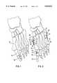
- FIG. 1is a top view of the bones of a foot subject to hallux valgus deformation.
- FIG. 2is a top view of the bones of the foot from FIG. 1 after correction of the hallux using the equipment of the present invention; this figure also shows corrections of the fifth metatarsal.
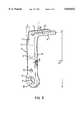
- FIG. 3is a perspective view of one embodiment of a device of the present invention.
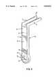
- FIG. 4is a perspective view of a variant of the device from FIG. 3.
- FIG. 5is a perspective view of a second variant of the device from FIG. 3, suitable for correction of the fifth metatarsal.
- FIG. 6is a perspective view of one embodiment of a complementary device of the invention.
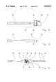
- FIG. 7is a top view of a drilling guide of the invention for boring tunnels in the bone for insertion of first anchor means.
- FIG. 8is a side view of the drilling guide from FIG. 7.
- FIG. 9is a front view of the drilling guide from FIG. 7.
- FIG. 10is a side view of a protractor of the invention used during surgery to measure the angle of the required angular correction.
- FIG. 11is a top view of the protractor from FIG. 10.
- FIG. 12is a side view of a first bending device member of the invention for imparting to the clip an angle conforming to the required angular correction.
- FIG. 13is a top view of the first bending device member from FIG. 12.
- FIG. 14is a side view of a second bending device member used in association with the first member from FIG. 12 to bend a clip to the required correction angle.
- the device of the inventionincludes a rigid elongate body 1 having a rectilinear first main segment 2 and a rectilinear second main segment 3 joined together by an angled joining area 4 at a chosen angle A to each other equal to the angular correction to be applied to a bone.
- First anchor means 5are provided on the first main segment 2 of the body 1 and are adapted to be fixed transversely in the bone.
- the first anchor means 5comprise two parallel pins 6 and 7 attached to the body 1, parallel to each other and generally oriented at a particular angle B (such as a right angle) to the longitudinal direction of the first main segment 2 and projecting from the concave face 8 of the body 1.
- the two parallel pins 6 and 7are offset laterally relative to each other and lie in a plane at the particular angle B (such as a right angle) to the longitudinal axis of the first main segment 2 of the body 1.
- the pins 6 and 7can thus be fixed into the bone during a first fixing step.
- Second anchor means 9are provided on the second main segment 3 of the body 1 and are fixed transversely in the bone at a later stage, after fixing the first anchor means 5.
- the second anchor means 9include a hole 10 into which fits the head of a screw whose shank projects from the concave face 8 of the body 1.
- the hole 10has a spherical annular portion 11, for example, matching a spherical bearing surface on the head of a bone screw.
- the body 1may advantageously also include near the hole 10 receiving the bone screw a secondary hole 12 for a removable pin for fixing the device temporarily to the bone or for strengthening its permanent fixing.
- the angle Acan advantageously be equal to approximately 15°. However, this angle can be different depending on the correction required to the metatarsus verus.
- the body 1in the angled joining area 4 to modify the angle A to match it to the required vertical correction, if any, associated with a lateral correction.
- the body 1is made from a material able to withstand without breaking and to retain permanent angular deformation in its angled joining area 4. Biologically compatible stainless steel can be used.
- the bodyis also given a shape enabling permanent angular deformation: in the angled joining area 4 the body has a thickness E substantially less than its width L1.
- the body 1is in the form of an elongate plate the width L1 of which is substantially greater than the thickness E. Its length L2 is between one third and one half the length of the bone to be corrected. For an application to correct a first metatarsal the length L2 is advantageously between approximately 2 cm and approximately 3 cm.
- the deviceincludes the same components as the FIG. 3 embodiment of the invention and the common components are identified by the same reference numbers.
- the body 1is a rectilinear plate and its angled joining area 4 is bent to an appropriate angle using a bending device, according to the required angular correction of the bone.
- the deviceincludes similar components to those of the FIG. 3 embodiment of the invention and these similar components are identified by the same reference numbers.
- the body 1is also a rectilinear plate and the angled joining area 4 is bent to an appropriate angle by means of a bending device.
- the first anchor means 5comprise a single pin 6. This device is suitable for correction of the fifth metatarsal.
- the pin or pins of the first anchor means 5are at a particular angle B to the first segment 2 of the body 1.
- the inventionprovides a drilling guide for boring penetration holes in the bone at the same angle B to the longitudinal direction of the bone.
- the drilling guide used for this purposeis shown in FIGS. 7 through 9 and has a body 40 with a plane lower bearing face 41. It is held by a transverse handle 42 and has two through-holes 43 and 44 perpendicular to the lower bearing face 41.
- the angle Bis a right angle.
- the holes 43 and 44can be inclined to provide an angle B other than 90°.
- a longitudinal hook 45locates the drilling guide relative to a bone end. Graduations 46 on the end of the body 40 allow lateral orientation adjustment of the bone parts on either side of an osteotomy if necessary.
- FIGS. 10 and 11To measure the required angle A of angular correction during surgery it is possible to use a protractor as shown in FIGS. 10 and 11.
- This devicehas a body 47 fastened to a handle 48 and including a rod 49 which is inserted into one of the tunnels previously bored in the bone using the drilling guide shown in FIGS. 7 through 9.
- a feeler 50is articulated to the body 47 about a transverse axis 51.
- the body 47is applied to the proximal part of the bone after osteotomy and the feeler 50 is applied to the distal part of the bone while adjusting the inclination of the distal part of the bone to obtain the required correction.
- the angle between the body 47 and the feeler 50can then be read off graduations 151 on the body across which moves a pointer 52 on the feeler 50.
- a bending deviceis used to conform the body 1 to the required angle A.
- the bending deviceincludes a first member shown in FIGS. 12 and 13 having a handle 53 and a body 54.
- the body 54includes a wide transverse groove 55 and a narrow longitudinal groove 56 shaped to enable lateral insertion of the end of the clip including the pins of the first anchor means 5.
- the pinsare inserted into the wide transverse groove 55.
- the end of the body 1passes through the narrow longitudinal groove 56.
- a lateral flange 57 carrying angular graduations 58is used to measure the angle A in the angled joining area of the body 1.
- the angle Ais adjusted using a second member shown in FIG. 14 including a handle 59 and a body 60 which has a longitudinal slot 61.
- the second main segment 3 of the body 1is inserted longitudinally into the slot 61, opposite the first main segment 2 of the body 1 inserted into the first member shown in FIGS. 12 and 13.
- the handles 53 and 59as shown by the arrow 62, the body 1 can be bent to the required angle A, read off on the graduations 58.
- FIG. 6shows a complementary device of the invention having a rigid elongate body 100 comprising a rectilinear first main segment 2 and a rectilinear second main segment 3 joined together in an angled joining area 4 at an angle substantially equal to the angular correction required, for example equal to approximately 10°.
- the first main segment 2includes first anchor means 5 and the second main segment 3 includes second anchor means 9.
- the first anchor means 5include a first pair of pins 13 and 14 offset longitudinally on the body 100.
- the end pin 13is longer than the intermediate pin 14.
- the second anchor means 9include a second pair of pins 15 and 16 offset longitudinally on the body 100, the end pin 16 being longer than the intermediate pin 15.
- the pins 13, 14, 15 and 16are advantageously parallel to each other and project from the convex side 17 of the body 100.
- the length of the body 100is advantageously between one third and one half the length of the bone to be corrected.
- the length of the body 1is advantageously between approximately 1 cm and approximately 2 cm.
- the equipment used to correct deformation of the footadvantageously includes a first device such as a clip 21 shown in FIGS. 3 to 5 shaped to fit to the first metatarsal 18 of the hallux and a complementary second device such as the clip shown in FIG. 6, shaped to fit to the first phalange 19 adjacent said first metatarsal 18.
- a first devicesuch as a clip 21 shown in FIGS. 3 to 5 shaped to fit to the first metatarsal 18 of the hallux
- a complementary second devicesuch as the clip shown in FIG. 6, shaped to fit to the first phalange 19 adjacent said first metatarsal 18.
- FIG. 1shows a foot suffering from hallux valgus deformation that is to be corrected: the hallux is formed by the first metatarsal 18, the first phalange 19 and the second phalange 20.
- the curvature of the halluxcauses inward angular projection of the joint between the metatarsal and the phalange.
- FIG. 2shows the same foot after correction by the equipment of the invention: the first metatarsal 18 is corrected by the clip 21 shown in FIGS. 3 through 5 and the first phalange 19 is corrected by the clip 22 shown in FIG. 6.
- two parallel tunnelsare bored into the spongy proximal part 24 of the epiphysis of the first metatarsal 18, at an angle B to the longitudinal axis of the metatarsal, the tunnels being positioned so that the angled joining area 4 of the clip 21 is substantially in line with the osteotomy 23;
- the clip 21is fitted by inserting the pins of the first anchor means 5 into the tunnels bored in the proximal part 24 of the first metatarsal 18, the body 1 of the clip 21 being bent first using the bending device to obtain the required correction as measured beforehand using an X-ray of the foot and/or during surgery using the protractor applied to the bone after osteotomy;
- the clip 21is immobilized temporarily by inserting a diaphysis pin 25 through the appropriate hole 12 as shown in FIGS. 3 through 5;
- the clip 21is fixed permanently by a bone screw 26 in the diaphysis of the first metatarsal 18;
- the diaphysis pin 25is either removed or can be left in place in the case of an unstable mounting.
- the first phalange 19has also to be corrected by an interior closing osteotomy 27 of the diaphysis.
- the angle of the osteotomyis determined by a cutting guide and can be approximately 5°, approximately 10 °or approximately 15°, for example.
- the closureis stabilized by the clip 22 shown in FIG. 6, i.e. a clip with four pins of unequal length, two pins being inserted into each bone fragment to prevent any movement.
- the clip 22is fitted after predrilling the bone using appropriate ancillary equipment.
- the ancillary equipment and the clip 22have an appropriate angular configuration to fit the shape of the diaphysis after closure of the osteotomy at the time of application.
- the predrillingis carried out so that the clip when fitted has its angled joining area 4 substantially in line with the osteotomy 27.
- the clip 22can be used independently of a clip 21.
- FIG. 2also shows correction of rotation of the fifth metatarsal 28 by the clip 29 with one pin as shown in FIG. 5.
- the clip 29is anchored by its single pin 6 in the first segment and fixed to the second segment by a bone screw 31.
Landscapes
- Health & Medical Sciences (AREA)
- Orthopedic Medicine & Surgery (AREA)
- Surgery (AREA)
- Life Sciences & Earth Sciences (AREA)
- Heart & Thoracic Surgery (AREA)
- Animal Behavior & Ethology (AREA)
- Engineering & Computer Science (AREA)
- Biomedical Technology (AREA)
- Neurology (AREA)
- Medical Informatics (AREA)
- Molecular Biology (AREA)
- Nuclear Medicine, Radiotherapy & Molecular Imaging (AREA)
- General Health & Medical Sciences (AREA)
- Public Health (AREA)
- Veterinary Medicine (AREA)
- Surgical Instruments (AREA)
- Orthopedics, Nursing, And Contraception (AREA)
- Control Of Metal Rolling (AREA)
Abstract
Description
This application is filed under 35 U.S.C.371, based on PCT/FR95/00544 which was filed on Apr. 26, 1995.
The present invention concerns equipment for correcting deformation of certain long bones, inparticular small long bones in the human body. The equipment of the invention is used in particular to correct deformation, mainly hallux valgus deformation, of the hallux (innermost digit) of the foot.
The hallux comprises three long bones in succession articulated to each other, namely the first metatarsal, the first phalange and the second phalange. A hallux valgus deformation is an excessive inward deviation of the hallux.
It is tempting to correct this excessive inward deviation by removal of bone from the first metatarsal (interior opening or exterior closing osteotomy). Unfortunately, until now, precise angular correction has not been possible for want of suitable osteosynthesis equipment.
Document WO-A-94 02073 describes an osteosynthesis clip for the head of the tibia or the head of the femur. This device has a rigid body, which is a priori non-deformable, curved (S-shape) and fastened at both ends to two divergent pins with teeth causing compression of bone fragments on either side of the fracture. Apart from the fact that a device of this kind is not capable of penetration into the cortical bone, which penetration is necessary for correcting deformations of the feet, and does not have any angular modification action due to its shape, any correction achieved is independent of the shape of the rigid body and depends only on the angle of the osteotomy prior to insertion of the pins. Given that it is always difficult to achieve a precise angle in osteotomy, the device does not easily achieve a precise angular correction. Also, the device compresses the bone fragments which means that it is not suitable for interior opening osteotomy.
Document FR-A-2 686 012 describes a plate and blade device for angular correction of the tibia. Because of the S-shape of the body and because of the presence of a blade member, the device is suitable only for correction of the tibia and is not appropriate for other bones such as the long bones of the foot. Also, because the body has to be very rigid to withstand the high mechanical stresses on the tibia, it is not deformable and the angle between the blade member and the body is fixed. The angular correction obtained by osteotomy is therefore adjusted by varying the angle at which the blade member penetrates the epiphysis, and by bringing the diaphysis progressively into contact with the body. This adjustment is difficult and delicate. Also, an offset results between the body and the external surface of the epiphysis, depending on the angular correction made. The device is not suitable for treatment of small long bones as the distance between the penetration orifice of the blade member and the osteotomy is then too small to allow variation in the angle of penetration. If an acute penetration angle were chosen, the blade member would impinge on the osteotomy.
Document EP-A-0 552 109 describes a clip for pinning a ligament to a bone. A device of this kind is not capable of angular correction and the proximity of its pins and its locking fingers means that it is unable to support an osteotomy.
Document FR-A-2 362 616 describes a clip to be shaped into a tube to hold a bone straight. This device is not capable of angular correction.
The problem to which the present invention is addressed is therefore that of providing equipment for easy and effective correction of deformation of small long bones, in particular hallux valgus deformation of the hallux. The equipment must provide the precise angular correction of itself, without requiring great accuracy of the osteotomy. The equipment must hold the adjacent portions of the bone at the correct angle after osteotomy, without making the bone fragile, and in particular allowing a maximum distance between the osteotomy and the fixing members penetrating the bone.
The equipment of the invention must also be usable for correcting associated or non-associated deformations in the vertical plane, such as lowering or elevation of the metatarsal, or in rotation (supination or pronation), or lengthwise (shortening or extension). It must also be usable for correction of other metatarsals, especially problems with rotation of the fifth metatarsal, and for correction of other small long bones such as the bones of the hand.
To achieve these and other objects the equipment of the invention for correcting deformation of long bones includes at least one bone holding device including:
a rigid elongate body having two rectilinear main segments joined together by an angled joining area at an angle (A) to each other which can be varied so that it is substantially equal to the required angular correction, said body being made from a material and having a shape adapted to withstand without breaking and to retain permanent angular deformation in the angled joining area,
first anchor means on the first main segment of the body adapted to be fixed transversely into the bone in a direction at a particular angle (B) such as right angle to the longitudinal axis of the bone, the first anchor means including at least one pin extending in a direction substantially at said particular angle (B) to the longitudinal axis of the first main segment of the body,
second anchor means on the second main segment of the body adapted to be fixed transversely in the bone at a subsequent stage, after fixing of the first anchor means so that after opening or closing osteotomy between two adjacent portions of the bone at an angle substantially equal to the required correction, and after anchoring of the first anchor means of the device at the particular angle (B) in the bone such that the angled joining area is in line with the osteotomy the device determines the angular offset between the two adjacent bone portions, subsequent anchoring of the second anchor means fixing the angular offset.
In a first embodiment of the invention:
the second anchor means include at least one hole adapted to fit a bone screw,
the anchor means are adapted to penetrate the bone and project from the concave face of the body.
A device of this kind including two body main segment pins is a clip suitable for correcting deformation of the first metatarsal.
A device of this kind including a single body main segment pin is a clip suitable for correcting deformation of the fifth metatarsal.
The invention also provides a complementary device having a rigid elongate body comprising a rectilinear first main segment and a rectilinear second main segment joined together at an angled joining area and wherein:
first anchor means include a first pair of pins offset longitudinally on the body,
second anchor means include a second pair of pins offset longitudinally on the body,
the pins project from the convex side of the body.
This complementary device is a clip suitable for correcting deformation of the first metatarsal.
The combination of the two devices is suitable for correction of the first metatarsal and the first phalange.
Other objects, features and advantages of the present invention will emerge from the following description of specific embodiments of the invention given with reference to the appended drawings.
FIG. 1 is a top view of the bones of a foot subject to hallux valgus deformation.
FIG. 2 is a top view of the bones of the foot from FIG. 1 after correction of the hallux using the equipment of the present invention; this figure also shows corrections of the fifth metatarsal.
FIG. 3 is a perspective view of one embodiment of a device of the present invention.
FIG. 4 is a perspective view of a variant of the device from FIG. 3.
FIG. 5 is a perspective view of a second variant of the device from FIG. 3, suitable for correction of the fifth metatarsal.
FIG. 6 is a perspective view of one embodiment of a complementary device of the invention.
FIG. 7 is a top view of a drilling guide of the invention for boring tunnels in the bone for insertion of first anchor means.
FIG. 8 is a side view of the drilling guide from FIG. 7.
FIG. 9 is a front view of the drilling guide from FIG. 7.
FIG. 10 is a side view of a protractor of the invention used during surgery to measure the angle of the required angular correction.
FIG. 11 is a top view of the protractor from FIG. 10.
FIG. 12 is a side view of a first bending device member of the invention for imparting to the clip an angle conforming to the required angular correction.
FIG. 13 is a top view of the first bending device member from FIG. 12.
FIG. 14 is a side view of a second bending device member used in association with the first member from FIG. 12 to bend a clip to the required correction angle.
In the embodiment of the invention shown in FIG. 3 the device of the invention includes a rigid elongate body 1 having a rectilinear firstmain segment 2 and a rectilinear secondmain segment 3 joined together by anangled joining area 4 at a chosen angle A to each other equal to the angular correction to be applied to a bone.
First anchor means 5 are provided on the firstmain segment 2 of the body 1 and are adapted to be fixed transversely in the bone. In the embodiment of the invention shown the first anchor means 5 comprise twoparallel pins main segment 2 and projecting from theconcave face 8 of the body 1. The twoparallel pins main segment 2 of the body 1. Thepins
Second anchor means 9 are provided on the secondmain segment 3 of the body 1 and are fixed transversely in the bone at a later stage, after fixing the first anchor means 5. In the embodiment of the invention shown in the figure the second anchor means 9 include ahole 10 into which fits the head of a screw whose shank projects from theconcave face 8 of the body 1. Thehole 10 has a sphericalannular portion 11, for example, matching a spherical bearing surface on the head of a bone screw.
The body 1 may advantageously also include near thehole 10 receiving the bone screw asecondary hole 12 for a removable pin for fixing the device temporarily to the bone or for strengthening its permanent fixing.
The angle A can advantageously be equal to approximately 15°. However, this angle can be different depending on the correction required to the metatarsus verus.
In all embodiments of the invention there is advantageously provision for deforming the body 1 in the angled joiningarea 4 to modify the angle A to match it to the required vertical correction, if any, associated with a lateral correction. To this end the body 1 is made from a material able to withstand without breaking and to retain permanent angular deformation in its angled joiningarea 4. Biologically compatible stainless steel can be used. The body is also given a shape enabling permanent angular deformation: in the angled joiningarea 4 the body has a thickness E substantially less than its width L1.
In the embodiment of the invention shown in FIG. 3 the body 1 is in the form of an elongate plate the width L1 of which is substantially greater than the thickness E. Its length L2 is between one third and one half the length of the bone to be corrected. For an application to correct a first metatarsal the length L2 is advantageously between approximately 2 cm and approximately 3 cm.
In the variant shown in FIG. 4 the device includes the same components as the FIG. 3 embodiment of the invention and the common components are identified by the same reference numbers.
However, in this embodiment of the invention the body 1 is a rectilinear plate and its angled joiningarea 4 is bent to an appropriate angle using a bending device, according to the required angular correction of the bone.
In the variant shown in FIG. 5 the device includes similar components to those of the FIG. 3 embodiment of the invention and these similar components are identified by the same reference numbers.
In the FIG. 5 variant the body 1 is also a rectilinear plate and the angled joiningarea 4 is bent to an appropriate angle by means of a bending device.
Also, in this variant, the first anchor means 5 comprise asingle pin 6. This device is suitable for correction of the fifth metatarsal.
The pin or pins of the first anchor means 5 are at a particular angle B to thefirst segment 2 of the body 1. The invention provides a drilling guide for boring penetration holes in the bone at the same angle B to the longitudinal direction of the bone.
The drilling guide used for this purpose is shown in FIGS. 7 through 9 and has abody 40 with a planelower bearing face 41. It is held by atransverse handle 42 and has two through-holes lower bearing face 41. In this embodiment of the invention the angle B is a right angle. Alternatively, theholes longitudinal hook 45 locates the drilling guide relative to a bone end.Graduations 46 on the end of thebody 40 allow lateral orientation adjustment of the bone parts on either side of an osteotomy if necessary.
To measure the required angle A of angular correction during surgery it is possible to use a protractor as shown in FIGS. 10 and 11. This device has abody 47 fastened to ahandle 48 and including arod 49 which is inserted into one of the tunnels previously bored in the bone using the drilling guide shown in FIGS. 7 through 9. Afeeler 50 is articulated to thebody 47 about atransverse axis 51. Thebody 47 is applied to the proximal part of the bone after osteotomy and thefeeler 50 is applied to the distal part of the bone while adjusting the inclination of the distal part of the bone to obtain the required correction. The angle between thebody 47 and thefeeler 50 can then be read offgraduations 151 on the body across which moves apointer 52 on thefeeler 50.
A bending device is used to conform the body 1 to the required angle A. The bending device includes a first member shown in FIGS. 12 and 13 having ahandle 53 and abody 54. Thebody 54 includes a widetransverse groove 55 and a narrowlongitudinal groove 56 shaped to enable lateral insertion of the end of the clip including the pins of the first anchor means 5. The pins are inserted into the widetransverse groove 55. The end of the body 1 passes through the narrowlongitudinal groove 56. Alateral flange 57 carryingangular graduations 58 is used to measure the angle A in the angled joining area of the body 1.
The angle A is adjusted using a second member shown in FIG. 14 including ahandle 59 and abody 60 which has alongitudinal slot 61. The secondmain segment 3 of the body 1 is inserted longitudinally into theslot 61, opposite the firstmain segment 2 of the body 1 inserted into the first member shown in FIGS. 12 and 13. By maneuvering thehandles arrow 62, the body 1 can be bent to the required angle A, read off on thegraduations 58.
FIG. 6 shows a complementary device of the invention having a rigidelongate body 100 comprising a rectilinear firstmain segment 2 and a rectilinear secondmain segment 3 joined together in an angled joiningarea 4 at an angle substantially equal to the angular correction required, for example equal to approximately 10°. The firstmain segment 2 includes first anchor means 5 and the secondmain segment 3 includes second anchor means 9.
In this complementary device, the first anchor means 5 include a first pair ofpins body 100. Theend pin 13 is longer than theintermediate pin 14.
Similarly, the second anchor means 9 include a second pair ofpins body 100, theend pin 16 being longer than theintermediate pin 15.
Thepins convex side 17 of thebody 100.
The length of thebody 100 is advantageously between one third and one half the length of the bone to be corrected. In the case of correcting the first phalange of the hallux, the length of the body 1 is advantageously between approximately 1 cm and approximately 2 cm.
As shown in FIG. 2, the equipment used to correct deformation of the foot, in particular hallux valgus deformation, advantageously includes a first device such as aclip 21 shown in FIGS. 3 to 5 shaped to fit to thefirst metatarsal 18 of the hallux and a complementary second device such as the clip shown in FIG. 6, shaped to fit to thefirst phalange 19 adjacent saidfirst metatarsal 18.
FIG. 1 shows a foot suffering from hallux valgus deformation that is to be corrected: the hallux is formed by thefirst metatarsal 18, thefirst phalange 19 and thesecond phalange 20. The curvature of the hallux causes inward angular projection of the joint between the metatarsal and the phalange.
FIG. 2 shows the same foot after correction by the equipment of the invention: thefirst metatarsal 18 is corrected by theclip 21 shown in FIGS. 3 through 5 and thefirst phalange 19 is corrected by theclip 22 shown in FIG. 6.
The procedure is as follows:
in an intermediate area of thefirst metatarsal 18, using a bone saw, an exterior opening epiphysis-diaphysis osteotomy 23 avoiding the exterior cortical bone tissue makes an angular space in the bone at an angle equal to the required angular correction;
using the appropriate drilling guide, two parallel tunnels are bored into the spongyproximal part 24 of the epiphysis of thefirst metatarsal 18, at an angle B to the longitudinal axis of the metatarsal, the tunnels being positioned so that the angled joiningarea 4 of theclip 21 is substantially in line with theosteotomy 23;
theclip 21 is fitted by inserting the pins of the first anchor means 5 into the tunnels bored in theproximal part 24 of thefirst metatarsal 18, the body 1 of theclip 21 being bent first using the bending device to obtain the required correction as measured beforehand using an X-ray of the foot and/or during surgery using the protractor applied to the bone after osteotomy;
theclip 21 is immobilized temporarily by inserting adiaphysis pin 25 through theappropriate hole 12 as shown in FIGS. 3 through 5;
correct alignment of the bone in all planes is verified;
theclip 21 is fixed permanently by abone screw 26 in the diaphysis of thefirst metatarsal 18;
thediaphysis pin 25 is either removed or can be left in place in the case of an unstable mounting.
If this correction of a hallux valgus deformation is insufficient, thefirst phalange 19 has also to be corrected by aninterior closing osteotomy 27 of the diaphysis. The angle of the osteotomy is determined by a cutting guide and can be approximately 5°, approximately 10 °or approximately 15°, for example.
The closure is stabilized by theclip 22 shown in FIG. 6, i.e. a clip with four pins of unequal length, two pins being inserted into each bone fragment to prevent any movement.
Theclip 22 is fitted after predrilling the bone using appropriate ancillary equipment. The ancillary equipment and theclip 22 have an appropriate angular configuration to fit the shape of the diaphysis after closure of the osteotomy at the time of application.
The predrilling is carried out so that the clip when fitted has its angled joiningarea 4 substantially in line with theosteotomy 27.
Of course, theclip 22 can be used independently of aclip 21.
FIG. 2 also shows correction of rotation of thefifth metatarsal 28 by theclip 29 with one pin as shown in FIG. 5. Afterintermediate osteotomy 30 and correction by axial rotation of the two sections of thefifth metatarsal 28 relative to each other, theclip 29 is anchored by itssingle pin 6 in the first segment and fixed to the second segment by abone screw 31.
The present invention is not limited to the embodiments explicitly described above, but includes variants and generalizations thereof within the scope of the following claims.
Claims (14)
1. Instrument for correcting deformation of small long bones in the human body comprising at least one bone holding device (21) including:
a rigid elongate body (1) having two rectilinear and entirely straight main segments (2, 3) joined together,
the two main segments being joined together by an angled joining area at a first angle which can be varied so that it is substantially equal to a required angular correction to be applied to the bone, first anchor means (5) formed in one-piece with the first main segment (2) of the body (1) adapted to be fixed transversely into a bone, the first anchor means (5) including at least one pin (6, 7) extending in a direction substantially at a second angle (B) relative to the longitudinal axis of the first main segment (2) of the body (1), second anchor means (9) on the second main segment (3) of the body (1) adapted to be fixed transversely in the bone at a subsequent stage, after fixing of the first anchor means (5),
wherein:
said first main segment (2) is directly connected to said first anchor means (5). and said second main segment (3) is directly connected to said second anchor means (9), and wherein said first and second main segments are directly connected to each other,
said body (1) is made from a material and has a shape adapted to withstand without breaking and to retain permanent angular deformation in the angled joining area (4),
the angled joining area has a thickness (E) substantially smaller than its width (L1),
so that the equipment is adapted to be bent by means of a bending device to obtain the required correction and after an opening osteotomy (23) or a closing osteotomy (27) between two adjacent portions of small long bones at said first angle substantially equal to the required correction, the first anchor means (5) of the device can be anchored in the bone in a direction at said second angle (B) to the longitudinal axis of the bone, with the angled joining area (4) in line with the osteotomy (23, 27), and the device (21) determines a required angular offset between the two adjacent bone portions, subsequent anchoring of the second anchor means (9) fixing the angular offset.
2. Instrument according to claim 1 wherein:
the second anchor means (9) include at least one hole (10) adapted to fit a bone screw,
the anchor means (5, 9) are adapted to penetrate the bone and project from a face (8) of the body (1) which face is opposite said first anchor means.
3. Instrument according to claim 2 wherein the body (1) includes near the hole (10) adapted to fit a bone screw a secondary hole (12) for a removable pin (25) for temporary fixing or strengthened fixing of the device (21) to the bone.
4. Instrument according to claim 1 wherein the angle (A) between the two main segments (2, 3) of the body (1) is equal to approximately 150.
5. Instrument according to claim 1 wherein the body (1) has a length (L2) between one third and one half the length of the bone which it is to correct.
6. Instrument according to claim 1 including it includes a drilling guide for boring penetration holes for the first anchor means (5) in a direction at a particular angle (B) to the longitudinal axis of the bone and a bending device adapted to shape the body (1) of the first bone holding device (21) to the required angle (A).
7. Instrument according to claim I including a complementary device having a rigid elongate body (100), the body having a convex side, the body comprising a rectilinear first main segment (2) and a rectilinear second main segment (3) joined together at an angled joining area (4) and wherein:
third anchor means (5) include a first pair of pins (13, 14) offset longitudinally on the body (100),
fourth anchor means (9) include a second pair of pins (15, 16) offset longitudinally on the body (100),
the pins (13-16) are parallel to each other and project from the convex side (17) of the body (100).
8. Instrument according to claim 7 wherein the pins (13, 14; 15, 16) of the same pair of anchor means are of different lengths, with an end pin (13, 16) longer than the intermediate pin (14, 15).
9. Instrument according to claim 7 wherein the angle between the two main segments (2, 3) of the body (100) is equal to approximately 100.
10. Method for correcting deformation of a small long bone in the human body, comprising the steps of:
providing a bone holding device including a rigid elongate body with two rectilinear main segments joined together. first anchor means on the first main segment of the body adapted to be fixed transversely into the bone, the first anchor means including at least one pin extending in a direction substantially at a particular angle relative to the longitudinal axis of the first main segment of the body, second anchor means on the second main segment of the body adapted to be fixed transversely in the bone, the two main segments being joined together by an angled joining area at an angle which is substantially equal to the required angular correction to be applied to the bone, said body being made from a material and having a shape adapted to withstand without breaking and to retain permanent angular deformation in the angled joining area, the angled joining area having a thickness substantially smaller than its width:
in an intermediate area of said small long bone, using a bone saw. providing an epiphysis-diaphysis osteotomy avoiding the exterior cortical bone tissue and making an angular space in the bone at an angle equal to the required angular correction.
using an appropriate drilling guide, boring two parallel tunnels into the spongy proximal part of the epiphysis of said small long bone, at said angle to the longitudinal axis of the bone, the tunnels being positioned so that the angled joining area of the bone holding device is substantially in line with the osteotomy;
inserting the pins of the first anchor means into the tunnels bored in the proximal part of said bone;
immobilizing temporarily said bone holding device by inserting a diaphysis pin through an appropriate hole:
verifying correct alignment of the bone in all planes; and
permanently fixing the bone holding device by a bone screw in the bone.
11. The method of claim 10 further comprising the preliminary steps of:
measuring the required angular correction on the bone;
bending the bone holding device using a bending device at an angle substantially equal to the required correction.
12. Instrument for correcting deformation of small long bones in the human body comprising at least one bone holding device (21) including:
a rigid elongate body (1) having two rectilinear main segments (2, 3) joined together,
the two main segments being joined together by an angled joining area at a first angle which can be varied so that it is substantially equal to a required angular correction to be applied to the bone,
first anchor means (5) on the first main segment (2) of the body (1) adapted to be fixed transversely into a bone, the first anchor means (5) including at least one pin (6, 7) extending in a direction substantially at a second angle (B) relative to the longitudinal axis of the first main segment (2) of the body (1),
second anchor means (9) on the second main segment (3) of the body (1) adapted to be fixed transversely in the bone at a subsequent stage, after fixing of the first anchor means (5),
wherein:
said body (1) is made from a material and has a shape adapted to withstand without breaking and to retain permanent angular deformation in the angled joining area (4),
the angled joining area has a thickness (E) substantially smaller than its width (L1),
so that the equipment is adapted to be bent by means of a bending device to obtain the required correction and after an opening osteotomy (23) or a closing osteotomy (27) between two adjacent portions of small long bones at said first angle substantially equal to the required correction, the first anchor means (5) of the device can be anchored in the bone in a direction at said second angle (B) to the longitudinal axis of the bone, with the angled joining area (4) in line with the osteotomy (23, 27), and the device (21) determines a required angular offset between the two adjacent bone portions, subsequent anchoring of the second anchor means (9) fixing the angular offset,
wherein the instrument includes a drilling guide for boring penetration holes for the first anchor means (5) in a direction at said second angle (B) to the longitudinal axis of the bone and a bending device adapted to shape the body (1) of the first bone holding device (21) to the required angle (A).
13. An instrument for correcting deformation of small long bones in the human body, the instrument comprising:
a rigid elongated body having first and second entirely straight main segments,
the first and second main segments being directly connected, respectively, to first and second anchor means, the anchor means comprising means for attaching the body to a bone, the first main segment and the first anchor means being formed in one-piece,
the first and second main segments also being directly connected to each other at an angle, wherein said angle of connection is controllably variable.
14. The instrument of claim 13, wherein the first anchor means is integrally formed with the body, and wherein the second anchor means is distinct from the body.
Applications Claiming Priority (3)
| Application Number | Priority Date | Filing Date | Title |
|---|---|---|---|
| FR9405332AFR2719211B1 (en) | 1994-04-27 | 1994-04-27 | Equipment for correcting foot deformities. |
| FR9405332 | 1994-04-27 | ||
| PCT/FR1995/000544WO1995028887A1 (en) | 1994-04-27 | 1995-04-26 | Apparatus for correcting long bone deformation |
Publications (1)
| Publication Number | Publication Date |
|---|---|
| US5810822Atrue US5810822A (en) | 1998-09-22 |
Family
ID=9462754
Family Applications (1)
| Application Number | Title | Priority Date | Filing Date |
|---|---|---|---|
| US08/732,318Expired - Fee RelatedUS5810822A (en) | 1994-04-27 | 1995-04-26 | Apparatus for correcting long bone deformation |
Country Status (10)
| Country | Link |
|---|---|
| US (1) | US5810822A (en) |
| EP (1) | EP0757545B1 (en) |
| JP (1) | JPH09512189A (en) |
| KR (1) | KR970702014A (en) |
| AT (1) | ATE203149T1 (en) |
| CA (1) | CA2188659A1 (en) |
| DE (1) | DE69521798T2 (en) |
| ES (1) | ES2161289T3 (en) |
| FR (1) | FR2719211B1 (en) |
| WO (1) | WO1995028887A1 (en) |
Cited By (120)
| Publication number | Priority date | Publication date | Assignee | Title |
|---|---|---|---|---|
| US5904683A (en)* | 1998-07-10 | 1999-05-18 | Sulzer Spine-Tech Inc. | Anterior cervical vertebral stabilizing device |
| RU2141805C1 (en)* | 1998-12-15 | 1999-11-27 | Васильев Алексей Викторович | Device for osteosynthesis |
| US6007536A (en)* | 1998-11-30 | 1999-12-28 | Yue; James J. | Variable angle blade plate for fixation of cancellous bone |
| US6168596B1 (en)* | 1999-11-09 | 2001-01-02 | Bioplate, Inc. | Cranial bone flap fixation clip |
| US6190389B1 (en)* | 1999-11-09 | 2001-02-20 | Bioplate, Inc. | Bone alignment and fixation device and method |
| US6302884B1 (en)* | 1999-11-09 | 2001-10-16 | Bioplate, Inc. | Bone alignment and fixation device and installation method |
| US6582435B2 (en) | 2001-11-29 | 2003-06-24 | Bioplate, Inc. | Bone alignment and fixation device and installation method, using guide tab |
| US6620165B2 (en) | 2001-11-26 | 2003-09-16 | Bioplate, Inc. | Bone alignment and fixation plate and installation method |
| US6652531B2 (en) | 2001-11-29 | 2003-11-25 | Bioplate, Inc. | Bone alignment and fixation device and installation method, using attachment structure |
| US6679885B2 (en) | 2001-11-29 | 2004-01-20 | Bioplate, Inc. | Bone alignment and fixation device and installation method, using multiple clip section attachment structure |
| US6709437B2 (en) | 2001-11-26 | 2004-03-23 | Bioplate, Inc. | Bone alignment and fixation device and installation method, using bowed strut attachment structure |
| US20040162574A1 (en)* | 2001-08-03 | 2004-08-19 | Viola Frank J. | Tissue marking apparatus and method |
| US20040210234A1 (en)* | 2003-02-26 | 2004-10-21 | Jean-Yves Coillard-Lavirotte | Anatomic miniplate for osteosynthesis of the first phalange |
| US20040236337A1 (en)* | 2003-04-02 | 2004-11-25 | Benoist Girard Sas | Greater trochanteric re-attachment device |
| US20050273112A1 (en)* | 2004-05-26 | 2005-12-08 | Mcnamara Michael G | Three-dimensional osteotomy device and method for treating bone deformities |
| RU2266719C2 (en)* | 2002-10-14 | 2005-12-27 | Федеральное государственное учреждение "Российский научно-исследовательский институт травматологии и ортопедии им.Р.Р.Вредена Федерального агентства по здравоохранению и социальному развитию" (ФГУ "РНИИТО им.Р.Р.Вредена Росздрава") | Y-shaped plate for osteosynthesis of epimetaphyseal fractures (variants) |
| US20060036243A1 (en)* | 2004-08-13 | 2006-02-16 | Ricardo Sasso | Replacement facet joint and method |
| US20060058795A1 (en)* | 2004-08-25 | 2006-03-16 | Howmedica Osteonics Corp. | Trochanteric cerclage plate |
| US20060264961A1 (en)* | 2003-10-25 | 2006-11-23 | Murray-Brown James H | Surgical jig |
| US20070055245A1 (en)* | 2004-08-13 | 2007-03-08 | Sasso Ricardo C | Replacement facet joint and method |
| US7229445B2 (en) | 2004-06-21 | 2007-06-12 | Synthes (Usa) | Bone plate with bladed portion |
| US20070233113A1 (en)* | 2005-09-16 | 2007-10-04 | Small Bone Innovations, Inc. | Condylar plate |
| US20090020584A1 (en)* | 2007-07-11 | 2009-01-22 | Michael Soltz | Surgical staple with augmented compression area |
| US20090062796A1 (en)* | 2006-05-10 | 2009-03-05 | Concepts In Medicine, Llc | Modular, blade-rod, intramedullary fixation device |
| US20090093849A1 (en)* | 2007-10-03 | 2009-04-09 | Greg Grabowski | Metatarsal fixation system |
| US20090177201A1 (en)* | 2007-11-14 | 2009-07-09 | Michael Soltz | Staple with Multiple Cross Sectional Shapes |
| US20090255978A1 (en)* | 2008-04-14 | 2009-10-15 | Tyco Healthcare Group Lp | Variable compression surgical fastener cartridge |
| US20090261144A1 (en)* | 2008-04-22 | 2009-10-22 | Kevin Sniffin | cartridge for applying varying amounts of tissue compression |
| US20090277949A1 (en)* | 2008-05-09 | 2009-11-12 | Frank Viola | Varying Tissue Compression With An Anvil Configuration |
| US20090277948A1 (en)* | 2008-05-09 | 2009-11-12 | John Beardsley | Variable Compression Surgical Fastener Cartridge |
| US20090277947A1 (en)* | 2008-05-09 | 2009-11-12 | Frank Viola | Varying tissue compression using take-up component |
| US20100006620A1 (en)* | 2007-03-22 | 2010-01-14 | Gregory Sorrentino | Apparatus for forming variable height surgical fasteners |
| US20100023052A1 (en)* | 2008-07-23 | 2010-01-28 | Tyco Healthcare Group Lp | Staple for use in surgical procedures |
| WO2010096724A1 (en)* | 2009-02-19 | 2010-08-26 | Nextremity Solutions, Llc | Bone joining apparatus and method |
| US20110046681A1 (en)* | 2008-10-02 | 2011-02-24 | Bernard Prandi | Orthopedic implant in the form of a plate to be fixed between two bone parts |
| US20110084112A1 (en)* | 2009-10-14 | 2011-04-14 | Tyco Healthcare Group Lp | Varying Tissue Compression Aided By Elastic Members |
| US7951176B2 (en) | 2003-05-30 | 2011-05-31 | Synthes Usa, Llc | Bone plate |
| US20110230906A1 (en)* | 2010-01-11 | 2011-09-22 | Arstasis, Inc. | Devices, methods and kits for forming tracts in tissue |
| US8100310B2 (en) | 2008-04-14 | 2012-01-24 | Tyco Healthcare Group Lp | Variable compression surgical fastener apparatus |
| US20120071924A1 (en)* | 2005-04-19 | 2012-03-22 | Medtronic | Antero lateral plating systems and methods for spinal stabilization |
| US8186556B2 (en) | 2008-05-09 | 2012-05-29 | Tyco Healthcare Group Lp | Variable compression surgical fastener apparatus |
| US8221421B2 (en) | 2001-02-23 | 2012-07-17 | Synthes Usa, Llc | Sternum fixation device |
| US8231040B2 (en) | 2008-04-14 | 2012-07-31 | Tyco Healthcare Group Lp | Variable compression surgical fastener cartridge |
| US8231041B2 (en) | 2008-04-14 | 2012-07-31 | Tyco Healthcare Group Lp | Variable compression surgical fastener cartridge |
| US8273111B2 (en) | 2008-07-02 | 2012-09-25 | Ebi, Llc | Growth control device |
| US8277459B2 (en) | 2009-09-25 | 2012-10-02 | Tarsus Medical Inc. | Methods and devices for treating a structural bone and joint deformity |
| US8464922B2 (en) | 2008-05-09 | 2013-06-18 | Covidien Lp | Variable compression surgical fastener cartridge |
| US20130245699A1 (en)* | 2011-09-06 | 2013-09-19 | Jorge L. Orbay | Fracture fixation plate, system and methods of use |
| US20130261622A1 (en)* | 2012-03-28 | 2013-10-03 | Chirmat Sarl | Implant for proximal fractures of long bones |
| EP2459078A4 (en)* | 2009-07-31 | 2014-01-22 | Robert J Medoff | Locking pin plate assembly adapted for fracture fixation |
| US20140039561A1 (en)* | 2012-08-03 | 2014-02-06 | Nextremity Solutions, Llc | Bone fixation device and method |
| US8652141B2 (en) | 2010-01-21 | 2014-02-18 | Tarsus Medical Inc. | Methods and devices for treating hallux valgus |
| US8696719B2 (en) | 2010-06-03 | 2014-04-15 | Tarsus Medical Inc. | Methods and devices for treating hallux valgus |
| US8858559B2 (en) | 2012-02-06 | 2014-10-14 | Medtronic Ps Medical, Inc. | Saw blade stability and collet system mechanism |
| US8870876B2 (en) | 2009-02-13 | 2014-10-28 | Tarsus Medical Inc. | Methods and devices for treating hallux valgus |
| US8936597B2 (en) | 2012-02-06 | 2015-01-20 | Medtronic Ps Medical, Inc. | Deflectable finger connection feature on surgical saw blade |
| US9072562B2 (en) | 2009-02-19 | 2015-07-07 | Nextremity Solutions, Inc. | Bone joining device, kit and method |
| US9138219B2 (en) | 2010-12-29 | 2015-09-22 | Tarsus Medical Inc. | Methods and devices for treating a syndesmosis injury |
| US20150359573A1 (en)* | 2014-06-17 | 2015-12-17 | Life Spine, Inc. | Compression Screw Systems for Compressing Bones of the Extremities |
| US9237911B2 (en) | 2009-07-31 | 2016-01-19 | Trimed, Inc | Locking pin plate assembly adapted for fracture fixation |
| WO2016033426A1 (en)* | 2014-08-28 | 2016-03-03 | Nextremity Solutions, Inc. | Bone fixation devices and methods |
| EP2937050A4 (en)* | 2012-12-19 | 2016-08-17 | Ind Medicas Sampedro S A S | Minimally invasive fixation plate for the correction of bunions |
| US9468465B2 (en) | 2009-02-19 | 2016-10-18 | Nextremity Solutions, Inc. | Reversible bone coupling device and method |
| US9622805B2 (en) | 2015-08-14 | 2017-04-18 | Treace Medical Concepts, Inc. | Bone positioning and preparing guide systems and methods |
| US9636111B2 (en) | 2007-05-07 | 2017-05-02 | Covidien Lp | Method of stapling tissues with a staple assembly |
| US9687250B2 (en) | 2015-01-07 | 2017-06-27 | Treace Medical Concepts, Inc. | Bone cutting guide systems and methods |
| US9907558B2 (en) | 2011-07-08 | 2018-03-06 | Smith & Nephew, Inc. | Osteotomy guide and method |
| US20180310972A1 (en)* | 2016-08-17 | 2018-11-01 | Globus Medical, Inc. | Stabilization systems |
| US10258328B2 (en) | 2015-01-12 | 2019-04-16 | Extremity Medical, Llc | Fixation assembly and method of use |
| US10335211B2 (en) | 2004-01-26 | 2019-07-02 | DePuy Synthes Products, Inc. | Highly-versatile variable-angle bone plate system |
| US10342586B2 (en) | 2003-08-26 | 2019-07-09 | DePuy Synthes Products, Inc. | Bone plate |
| US10342590B2 (en) | 2015-08-14 | 2019-07-09 | Treace Medical Concepts, Inc. | Tarsal-metatarsal joint procedure utilizing fulcrum |
| US10357260B2 (en) | 2015-11-02 | 2019-07-23 | First Ray, LLC | Orthopedic fastener, retainer, and guide methods |
| US10376367B2 (en) | 2015-07-02 | 2019-08-13 | First Ray, LLC | Orthopedic fasteners, instruments and methods |
| US10441753B2 (en) | 2012-05-25 | 2019-10-15 | Arstasis, Inc. | Vascular access configuration |
| US10512470B1 (en) | 2016-08-26 | 2019-12-24 | Treace Medical Concepts, Inc. | Osteotomy procedure for correcting bone misalignment |
| US10524808B1 (en) | 2016-11-11 | 2020-01-07 | Treace Medical Concepts, Inc. | Devices and techniques for performing an osteotomy procedure on a first metatarsal to correct a bone misalignment |
| US10555757B2 (en) | 2014-07-15 | 2020-02-11 | Treace Medical Concepts, Inc. | Bone positioning and cutting system and method |
| US10575862B2 (en) | 2015-09-18 | 2020-03-03 | Treace Medical Concepts, Inc. | Joint spacer systems and methods |
| US10624686B2 (en) | 2016-09-08 | 2020-04-21 | DePuy Synthes Products, Inc. | Variable angel bone plate |
| US10653464B2 (en) | 2014-02-12 | 2020-05-19 | Life Spine, Inc. | Foot bone plate providing fixation and compression |
| US10653467B2 (en) | 2015-05-06 | 2020-05-19 | Treace Medical Concepts, Inc. | Intra-osseous plate system and method |
| US10675447B2 (en) | 2012-05-25 | 2020-06-09 | Arstasis, Inc. | Vascular access configuration |
| US20200253650A1 (en)* | 2018-07-11 | 2020-08-13 | Crossroads Extremity Systems, Llc | Bunion correction system and method |
| US10772665B2 (en) | 2018-03-29 | 2020-09-15 | DePuy Synthes Products, Inc. | Locking structures for affixing bone anchors to a bone plate, and related systems and methods |
| US10820930B2 (en) | 2016-09-08 | 2020-11-03 | DePuy Synthes Products, Inc. | Variable angle bone plate |
| US10849631B2 (en) | 2015-02-18 | 2020-12-01 | Treace Medical Concepts, Inc. | Pivotable bone cutting guide useful for bone realignment and compression techniques |
| US10849663B2 (en) | 2015-07-14 | 2020-12-01 | Treace Medical Concepts, Inc. | Bone cutting guide systems and methods |
| US10874446B2 (en) | 2015-07-14 | 2020-12-29 | Treace Medical Concepts, Inc. | Bone positioning guide |
| US10905476B2 (en) | 2016-09-08 | 2021-02-02 | DePuy Synthes Products, Inc. | Variable angle bone plate |
| US10925651B2 (en) | 2018-12-21 | 2021-02-23 | DePuy Synthes Products, Inc. | Implant having locking holes with collection cavity for shavings |
| US10939939B1 (en) | 2017-02-26 | 2021-03-09 | Treace Medical Concepts, Inc. | Fulcrum for tarsal-metatarsal joint procedure |
| US11013541B2 (en) | 2018-04-30 | 2021-05-25 | DePuy Synthes Products, Inc. | Threaded locking structures for affixing bone anchors to a bone plate, and related systems and methods |
| US11026727B2 (en) | 2018-03-20 | 2021-06-08 | DePuy Synthes Products, Inc. | Bone plate with form-fitting variable-angle locking hole |
| US11259851B2 (en) | 2003-08-26 | 2022-03-01 | DePuy Synthes Products, Inc. | Bone plate |
| US11278337B2 (en) | 2015-08-14 | 2022-03-22 | Treace Medical Concepts, Inc. | Tarsal-metatarsal joint procedure utilizing fulcrum |
| US11291484B2 (en) | 2004-01-26 | 2022-04-05 | DePuy Synthes Products, Inc. | Highly-versatile variable-angle bone plate system |
| US20220409248A1 (en)* | 2019-08-07 | 2022-12-29 | Crossroads Extremity Systems, Llc | Bunion correction system and method |
| US11583323B2 (en) | 2018-07-12 | 2023-02-21 | Treace Medical Concepts, Inc. | Multi-diameter bone pin for installing and aligning bone fixation plate while minimizing bone damage |
| US11596443B2 (en) | 2018-07-11 | 2023-03-07 | Treace Medical Concepts, Inc. | Compressor-distractor for angularly realigning bone portions |
| US11607250B2 (en) | 2019-02-13 | 2023-03-21 | Treace Medical Concepts, Inc. | Tarsal-metatarsal joint procedure utilizing compressor-distractor and instrument providing sliding surface |
| US11622797B2 (en) | 2020-01-31 | 2023-04-11 | Treace Medical Concepts, Inc. | Metatarsophalangeal joint preparation and metatarsal realignment for fusion |
| US11627954B2 (en) | 2019-08-07 | 2023-04-18 | Treace Medical Concepts, Inc. | Bi-planar instrument for bone cutting and joint realignment procedure |
| US11660133B2 (en) | 2018-10-26 | 2023-05-30 | Zimmer, Inc. | Bone coupling device and method |
| USD1011524S1 (en) | 2022-02-23 | 2024-01-16 | Treace Medical Concepts, Inc. | Compressor-distractor for the foot |
| US11889998B1 (en) | 2019-09-12 | 2024-02-06 | Treace Medical Concepts, Inc. | Surgical pin positioning lock |
| US11890039B1 (en) | 2019-09-13 | 2024-02-06 | Treace Medical Concepts, Inc. | Multi-diameter K-wire for orthopedic applications |
| US11931106B2 (en) | 2019-09-13 | 2024-03-19 | Treace Medical Concepts, Inc. | Patient-specific surgical methods and instrumentation |
| US11986251B2 (en) | 2019-09-13 | 2024-05-21 | Treace Medical Concepts, Inc. | Patient-specific osteotomy instrumentation |
| US12004789B2 (en) | 2020-05-19 | 2024-06-11 | Treace Medical Concepts, Inc. | Devices and techniques for treating metatarsus adductus |
| USD1051382S1 (en) | 2022-02-23 | 2024-11-12 | Treace Medical Concepts, Inc. | Lesser metatarsal cut guide |
| US12161371B2 (en) | 2021-01-18 | 2024-12-10 | Treace Medical Concepts, Inc. | Contoured bone plate with locking screw for bone compression, particularly across a tarsometatarsal joint |
| USD1057155S1 (en) | 2022-02-23 | 2025-01-07 | Treace Medical Concepts, Inc. | Lesser metatarsal cut guide with parallel cut faces |
| US12193683B2 (en) | 2021-05-20 | 2025-01-14 | Treace Medical Concepts, Inc. | Cut guide with integrated joint realignment features |
| USD1068078S1 (en) | 2023-02-08 | 2025-03-25 | Treace Medical Concepts, Inc. | Handle for an orthopedic instrument |
| USD1068077S1 (en) | 2023-02-08 | 2025-03-25 | Treace Medical Concepts, Inc. | Orthopedic rasp for preparing an intercuneiform joint |
| USD1075012S1 (en) | 2022-02-23 | 2025-05-13 | Treace Medical Concepts, Inc. | Metatarsal lateral release instrument |
| US12310603B2 (en) | 2021-02-18 | 2025-05-27 | Treace Medical Concepts, Inc. | System and technique for metatarsal realignment with reduced incision length |
| USD1079011S1 (en) | 2022-02-23 | 2025-06-10 | Treace Medical Concepts, Inc. | Metatarsal cut guide with parallel cut faces |
| US12440250B2 (en) | 2024-02-05 | 2025-10-14 | Treace Medical Concepts, Inc. | Multi-diameter K-wire for orthopedic applications |
Families Citing this family (6)
| Publication number | Priority date | Publication date | Assignee | Title |
|---|---|---|---|---|
| US5676667A (en)* | 1995-12-08 | 1997-10-14 | Hausman; Michael | Bone fixation apparatus and method |
| SE510025C2 (en)* | 1996-05-10 | 1999-04-12 | Robert J Medoff | Graft material retaining device |
| FR2764183B1 (en)* | 1997-06-09 | 1999-11-05 | Jacques Afriat | MATERIAL ALLOWING THE CORRECTION OF "HALLUX VALGUS" |
| RU2402294C1 (en)* | 2009-04-06 | 2010-10-27 | Общество с ограниченной ответственностью "Медико-инженерный центр сплавов с памятью формы" | Synostosis apparatus for forefoot reconstruction |
| RU2402295C1 (en)* | 2009-04-13 | 2010-10-27 | Общество с ограниченной ответственностью "Медико-инженерный центр сплавов с памятью формы" | Synostosis apparatus for three instep bones |
| RU174964U1 (en)* | 2017-08-01 | 2017-11-13 | Общество с ограниченной ответственностью "Научно-производственная компания "СИНТЕЛ" | Lockable intramedullary spiral retainer |
Citations (16)
| Publication number | Priority date | Publication date | Assignee | Title |
|---|---|---|---|---|
| US2494229A (en)* | 1946-07-08 | 1950-01-10 | John G Collison | Bone surgery |
| FR2362616A1 (en)* | 1976-08-26 | 1978-03-24 | Duyck Jean | Metatarsal osteotomy anchor plate - has curved support with hooks, and holes for anchoring screws |
| FR2456506A1 (en)* | 1979-05-17 | 1980-12-12 | Hug Gerhard Gmbh | DEVICE FOR GUIDING SURGICAL INSTRUMENTS DURING OSTEOTOMY ON HUMAN ILIA BONE |
| GB2126903A (en)* | 1982-09-13 | 1984-04-04 | Elke Streli | Pronged plate for resetting fractured bones |
| US4632102A (en)* | 1981-08-20 | 1986-12-30 | Comparetto John E | Bone wedge osteotomy method |
| US4788970A (en)* | 1986-04-01 | 1988-12-06 | Huta Baildon | Drill setting guide for drilling holes in bones |
| DE3724479A1 (en)* | 1987-07-24 | 1989-02-02 | Jansson Volkmar Dipl Ing Dr Me | Bending device for the individual pre-bending of osteosynthesis plates during surgery |
| US4848328A (en)* | 1986-05-20 | 1989-07-18 | Laboureau Jacques P | Agraffe for osteosynthesis |
| US4913144A (en)* | 1988-08-03 | 1990-04-03 | D.A.O. S.R.L. | Adjustable staple |
| FR2676353A1 (en)* | 1991-05-15 | 1992-11-20 | Biomecanique Integree | Tibial osteotomy plate or the like |
| US5197966A (en)* | 1992-05-22 | 1993-03-30 | Sommerkamp T Greg | Radiodorsal buttress blade plate implant for repairing distal radius fractures |
| FR2686012A1 (en)* | 1992-01-09 | 1993-07-16 | Godeau Denis | Blade plate for tibial osteotomy and device for positioning it |
| EP0552109A1 (en)* | 1992-01-17 | 1993-07-21 | Cendis Medical Sarl | Bone staple |
| WO1994002073A1 (en)* | 1992-07-24 | 1994-02-03 | Laboureau Jacques Philippe | Osteosynthesis plate-staple for osteotomy |
| US5470335A (en)* | 1992-05-03 | 1995-11-28 | Technology Finance Corporation (Proprietary) Limited | Method for carrying out an osteotomy procedure |
| US5591168A (en)* | 1993-10-25 | 1997-01-07 | Tornier S.A. | Device for stabilizing fractures of the upper end of the femur |
- 1994
- 1994-04-27FRFR9405332Apatent/FR2719211B1/ennot_activeExpired - Fee Related
- 1995
- 1995-04-26USUS08/732,318patent/US5810822A/ennot_activeExpired - Fee Related
- 1995-04-26DEDE69521798Tpatent/DE69521798T2/ennot_activeExpired - Lifetime
- 1995-04-26ESES95918643Tpatent/ES2161289T3/ennot_activeExpired - Lifetime
- 1995-04-26JPJP7527416Apatent/JPH09512189A/enactivePending
- 1995-04-26EPEP95918643Apatent/EP0757545B1/ennot_activeExpired - Lifetime
- 1995-04-26CACA002188659Apatent/CA2188659A1/ennot_activeAbandoned
- 1995-04-26WOPCT/FR1995/000544patent/WO1995028887A1/enactiveIP Right Grant
- 1995-04-26ATAT95918643Tpatent/ATE203149T1/ennot_activeIP Right Cessation
- 1995-04-26KRKR1019960705988Apatent/KR970702014A/ennot_activeWithdrawn
Patent Citations (16)
| Publication number | Priority date | Publication date | Assignee | Title |
|---|---|---|---|---|
| US2494229A (en)* | 1946-07-08 | 1950-01-10 | John G Collison | Bone surgery |
| FR2362616A1 (en)* | 1976-08-26 | 1978-03-24 | Duyck Jean | Metatarsal osteotomy anchor plate - has curved support with hooks, and holes for anchoring screws |
| FR2456506A1 (en)* | 1979-05-17 | 1980-12-12 | Hug Gerhard Gmbh | DEVICE FOR GUIDING SURGICAL INSTRUMENTS DURING OSTEOTOMY ON HUMAN ILIA BONE |
| US4632102A (en)* | 1981-08-20 | 1986-12-30 | Comparetto John E | Bone wedge osteotomy method |
| GB2126903A (en)* | 1982-09-13 | 1984-04-04 | Elke Streli | Pronged plate for resetting fractured bones |
| US4788970A (en)* | 1986-04-01 | 1988-12-06 | Huta Baildon | Drill setting guide for drilling holes in bones |
| US4848328A (en)* | 1986-05-20 | 1989-07-18 | Laboureau Jacques P | Agraffe for osteosynthesis |
| DE3724479A1 (en)* | 1987-07-24 | 1989-02-02 | Jansson Volkmar Dipl Ing Dr Me | Bending device for the individual pre-bending of osteosynthesis plates during surgery |
| US4913144A (en)* | 1988-08-03 | 1990-04-03 | D.A.O. S.R.L. | Adjustable staple |
| FR2676353A1 (en)* | 1991-05-15 | 1992-11-20 | Biomecanique Integree | Tibial osteotomy plate or the like |
| FR2686012A1 (en)* | 1992-01-09 | 1993-07-16 | Godeau Denis | Blade plate for tibial osteotomy and device for positioning it |
| EP0552109A1 (en)* | 1992-01-17 | 1993-07-21 | Cendis Medical Sarl | Bone staple |
| US5470335A (en)* | 1992-05-03 | 1995-11-28 | Technology Finance Corporation (Proprietary) Limited | Method for carrying out an osteotomy procedure |
| US5197966A (en)* | 1992-05-22 | 1993-03-30 | Sommerkamp T Greg | Radiodorsal buttress blade plate implant for repairing distal radius fractures |
| WO1994002073A1 (en)* | 1992-07-24 | 1994-02-03 | Laboureau Jacques Philippe | Osteosynthesis plate-staple for osteotomy |
| US5591168A (en)* | 1993-10-25 | 1997-01-07 | Tornier S.A. | Device for stabilizing fractures of the upper end of the femur |
Cited By (244)
| Publication number | Priority date | Publication date | Assignee | Title |
|---|---|---|---|---|
| US5904683A (en)* | 1998-07-10 | 1999-05-18 | Sulzer Spine-Tech Inc. | Anterior cervical vertebral stabilizing device |
| US6007536A (en)* | 1998-11-30 | 1999-12-28 | Yue; James J. | Variable angle blade plate for fixation of cancellous bone |
| RU2141805C1 (en)* | 1998-12-15 | 1999-11-27 | Васильев Алексей Викторович | Device for osteosynthesis |
| US6168596B1 (en)* | 1999-11-09 | 2001-01-02 | Bioplate, Inc. | Cranial bone flap fixation clip |
| US6190389B1 (en)* | 1999-11-09 | 2001-02-20 | Bioplate, Inc. | Bone alignment and fixation device and method |
| US6302884B1 (en)* | 1999-11-09 | 2001-10-16 | Bioplate, Inc. | Bone alignment and fixation device and installation method |
| WO2001037720A3 (en)* | 1999-11-09 | 2001-12-27 | Bioplate Inc | Bone alignment and fixation device and installation method |
| US6511482B1 (en) | 1999-11-09 | 2003-01-28 | Bioplate, Inc. | Cranial bone flap fixation clip |
| US8876824B2 (en) | 2001-02-23 | 2014-11-04 | DePuy Synthes Products, LLC | Sternum fixation device |
| US8221421B2 (en) | 2001-02-23 | 2012-07-17 | Synthes Usa, Llc | Sternum fixation device |
| US7497862B2 (en) | 2001-08-03 | 2009-03-03 | Tyco Healthcare Group Lp | Tissue marking apparatus and method |
| US20040162574A1 (en)* | 2001-08-03 | 2004-08-19 | Viola Frank J. | Tissue marking apparatus and method |
| US6709437B2 (en) | 2001-11-26 | 2004-03-23 | Bioplate, Inc. | Bone alignment and fixation device and installation method, using bowed strut attachment structure |
| US6620165B2 (en) | 2001-11-26 | 2003-09-16 | Bioplate, Inc. | Bone alignment and fixation plate and installation method |
| US6679885B2 (en) | 2001-11-29 | 2004-01-20 | Bioplate, Inc. | Bone alignment and fixation device and installation method, using multiple clip section attachment structure |
| US6652531B2 (en) | 2001-11-29 | 2003-11-25 | Bioplate, Inc. | Bone alignment and fixation device and installation method, using attachment structure |
| US6582435B2 (en) | 2001-11-29 | 2003-06-24 | Bioplate, Inc. | Bone alignment and fixation device and installation method, using guide tab |
| RU2266719C2 (en)* | 2002-10-14 | 2005-12-27 | Федеральное государственное учреждение "Российский научно-исследовательский институт травматологии и ортопедии им.Р.Р.Вредена Федерального агентства по здравоохранению и социальному развитию" (ФГУ "РНИИТО им.Р.Р.Вредена Росздрава") | Y-shaped plate for osteosynthesis of epimetaphyseal fractures (variants) |
| US20040210234A1 (en)* | 2003-02-26 | 2004-10-21 | Jean-Yves Coillard-Lavirotte | Anatomic miniplate for osteosynthesis of the first phalange |
| US7611513B2 (en) | 2003-04-02 | 2009-11-03 | Benoist Girard Sas | Greater trochanteric re-attachment device |
| US20040236337A1 (en)* | 2003-04-02 | 2004-11-25 | Benoist Girard Sas | Greater trochanteric re-attachment device |
| US9308034B2 (en) | 2003-05-30 | 2016-04-12 | DePuy Synthes Products, Inc. | Bone plate |
| US7951176B2 (en) | 2003-05-30 | 2011-05-31 | Synthes Usa, Llc | Bone plate |
| US11419647B2 (en) | 2003-05-30 | 2022-08-23 | DePuy Synthes Products, Inc. | Bone plate |
| US9931148B2 (en) | 2003-05-30 | 2018-04-03 | DePuy Synthes Products, Inc. | Bone plate |
| US10231768B2 (en) | 2003-05-30 | 2019-03-19 | DePuy Synthes Products, Inc. | Methods for implanting bone plates |
| US10653466B2 (en) | 2003-05-30 | 2020-05-19 | DePuy Synthes Products, Inc. | Bone plate |
| US11259851B2 (en) | 2003-08-26 | 2022-03-01 | DePuy Synthes Products, Inc. | Bone plate |
| US10342586B2 (en) | 2003-08-26 | 2019-07-09 | DePuy Synthes Products, Inc. | Bone plate |
| US20060264961A1 (en)* | 2003-10-25 | 2006-11-23 | Murray-Brown James H | Surgical jig |
| US11291484B2 (en) | 2004-01-26 | 2022-04-05 | DePuy Synthes Products, Inc. | Highly-versatile variable-angle bone plate system |
| US10335211B2 (en) | 2004-01-26 | 2019-07-02 | DePuy Synthes Products, Inc. | Highly-versatile variable-angle bone plate system |
| US20050273112A1 (en)* | 2004-05-26 | 2005-12-08 | Mcnamara Michael G | Three-dimensional osteotomy device and method for treating bone deformities |
| US7229445B2 (en) | 2004-06-21 | 2007-06-12 | Synthes (Usa) | Bone plate with bladed portion |
| US20060036243A1 (en)* | 2004-08-13 | 2006-02-16 | Ricardo Sasso | Replacement facet joint and method |
| US8608779B2 (en) | 2004-08-13 | 2013-12-17 | Ricardo C. Sasso | Replacement facet joint and method |
| US8491634B2 (en) | 2004-08-13 | 2013-07-23 | Ricardo C. Sasso | Replacement facet joint and method |
| US7846184B2 (en)* | 2004-08-13 | 2010-12-07 | Sasso Ricardo C | Replacement facet joint and method |
| US20080249571A1 (en)* | 2004-08-13 | 2008-10-09 | Sasso Ricardo C | Replacement facet joint and method |
| US20070055245A1 (en)* | 2004-08-13 | 2007-03-08 | Sasso Ricardo C | Replacement facet joint and method |
| US20060058795A1 (en)* | 2004-08-25 | 2006-03-16 | Howmedica Osteonics Corp. | Trochanteric cerclage plate |
| US7229444B2 (en)* | 2004-08-25 | 2007-06-12 | Howmedica Osteonics Corp. | Trochanteric cerclage plate |
| US20120071924A1 (en)* | 2005-04-19 | 2012-03-22 | Medtronic | Antero lateral plating systems and methods for spinal stabilization |
| US8470007B2 (en)* | 2005-04-19 | 2013-06-25 | Warsaw Orthopedic, Inc. | Antero-lateral plating systems and methods for spinal stabilization |
| US20070233113A1 (en)* | 2005-09-16 | 2007-10-04 | Small Bone Innovations, Inc. | Condylar plate |
| US20090062796A1 (en)* | 2006-05-10 | 2009-03-05 | Concepts In Medicine, Llc | Modular, blade-rod, intramedullary fixation device |
| US8211107B2 (en)* | 2006-05-10 | 2012-07-03 | Concepts In Medicine, Llc | Modular, blade-rod, intramedullary fixation device |
| US8205780B2 (en) | 2007-03-22 | 2012-06-26 | Tyco Healthcare Group Lp | Apparatus for forming variable height surgical fasteners |
| US9597073B2 (en) | 2007-03-22 | 2017-03-21 | Covidien Lp | Apparatus for forming variable height surgical fasteners |
| US20100006620A1 (en)* | 2007-03-22 | 2010-01-14 | Gregory Sorrentino | Apparatus for forming variable height surgical fasteners |
| US8403198B2 (en) | 2007-03-22 | 2013-03-26 | Covidien Lp | Apparatus for forming variable height surgical fasteners |
| US9636111B2 (en) | 2007-05-07 | 2017-05-02 | Covidien Lp | Method of stapling tissues with a staple assembly |
| US20090020584A1 (en)* | 2007-07-11 | 2009-01-22 | Michael Soltz | Surgical staple with augmented compression area |
| US9254131B2 (en) | 2007-07-11 | 2016-02-09 | Covidien Lp | Surgical staple with augmented compression area |
| US8348972B2 (en) | 2007-07-11 | 2013-01-08 | Covidien Lp | Surgical staple with augmented compression area |
| US20090093849A1 (en)* | 2007-10-03 | 2009-04-09 | Greg Grabowski | Metatarsal fixation system |
| US20090177201A1 (en)* | 2007-11-14 | 2009-07-09 | Michael Soltz | Staple with Multiple Cross Sectional Shapes |
| US8424735B2 (en) | 2008-04-14 | 2013-04-23 | Covidien Lp | Variable compression surgical fastener cartridge |
| US8448832B2 (en) | 2008-04-14 | 2013-05-28 | Covidien Lp | Variable compression surgical fastener cartridge |
| US8231041B2 (en) | 2008-04-14 | 2012-07-31 | Tyco Healthcare Group Lp | Variable compression surgical fastener cartridge |
| US9463017B2 (en) | 2008-04-14 | 2016-10-11 | Covidien Lp | Variable compression surgical fastener cartridge |
| US20090255978A1 (en)* | 2008-04-14 | 2009-10-15 | Tyco Healthcare Group Lp | Variable compression surgical fastener cartridge |
| US8231040B2 (en) | 2008-04-14 | 2012-07-31 | Tyco Healthcare Group Lp | Variable compression surgical fastener cartridge |
| US8100310B2 (en) | 2008-04-14 | 2012-01-24 | Tyco Healthcare Group Lp | Variable compression surgical fastener apparatus |
| US7926691B2 (en) | 2008-04-14 | 2011-04-19 | Tyco Healthcare Group, L.P. | Variable compression surgical fastener cartridge |
| US8028884B2 (en) | 2008-04-22 | 2011-10-04 | Tyco Healthcare Group Lp | Cartridge for applying varying amounts of tissue compression |
| US20090261144A1 (en)* | 2008-04-22 | 2009-10-22 | Kevin Sniffin | cartridge for applying varying amounts of tissue compression |
| US8496156B2 (en) | 2008-04-22 | 2013-07-30 | Covidien Lp | Cartridge for applying varying amounts of tissue compression |
| US10085754B2 (en) | 2008-04-22 | 2018-10-02 | Covidien Lp | Cartridge for applying varying amounts of tissue compression |
| US9364225B2 (en) | 2008-04-22 | 2016-06-14 | Covidien Lp | Cartridge for applying varying amounts of tissue compression |
| US8256655B2 (en) | 2008-04-22 | 2012-09-04 | Tyco Healthcare Group Lp | Cartridge for applying varying amounts of tissue compression |
| US8186556B2 (en) | 2008-05-09 | 2012-05-29 | Tyco Healthcare Group Lp | Variable compression surgical fastener apparatus |
| US11446030B2 (en) | 2008-05-09 | 2022-09-20 | Covidien Lp | Variable compression surgical fastener cartridge |
| US8464922B2 (en) | 2008-05-09 | 2013-06-18 | Covidien Lp | Variable compression surgical fastener cartridge |
| US9844370B2 (en) | 2008-05-09 | 2017-12-19 | Covidien Lp | Varying tissue compression with an anvil configuration |
| US8091756B2 (en) | 2008-05-09 | 2012-01-10 | Tyco Healthcare Group Lp | Varying tissue compression using take-up component |
| US20090277947A1 (en)* | 2008-05-09 | 2009-11-12 | Frank Viola | Varying tissue compression using take-up component |
| US8342380B2 (en) | 2008-05-09 | 2013-01-01 | Covidien Lp | Variable compression surgical fastener apparatus |
| US20090277948A1 (en)* | 2008-05-09 | 2009-11-12 | John Beardsley | Variable Compression Surgical Fastener Cartridge |
| US9113870B2 (en) | 2008-05-09 | 2015-08-25 | Covidien Lp | Variable compression surgical fastener apparatus |
| US9016541B2 (en) | 2008-05-09 | 2015-04-28 | Covidien Lp | Varying tissue compression with an anvil configuration |
| US8967446B2 (en) | 2008-05-09 | 2015-03-03 | Covidien Lp | Variable compression surgical fastener cartridge |
| US9867616B2 (en) | 2008-05-09 | 2018-01-16 | Covidien Lp | Variable compression surgical fastener cartridge |
| US20090277949A1 (en)* | 2008-05-09 | 2009-11-12 | Frank Viola | Varying Tissue Compression With An Anvil Configuration |
| US10130401B2 (en) | 2008-07-02 | 2018-11-20 | Biomet Manufacturing, Llc | Growth control device |
| US8273111B2 (en) | 2008-07-02 | 2012-09-25 | Ebi, Llc | Growth control device |
| US9579134B2 (en) | 2008-07-02 | 2017-02-28 | Biomet Manufacturing, Llc | Growth control device |
| US20100023052A1 (en)* | 2008-07-23 | 2010-01-28 | Tyco Healthcare Group Lp | Staple for use in surgical procedures |
| US9693771B2 (en) | 2008-07-23 | 2017-07-04 | Covidien Lp | Method of forming a staple for use in surgical procedures |
| US8579938B2 (en) | 2008-07-23 | 2013-11-12 | Covidien Lp | Staple for use in surgical procedures |
| US20110046681A1 (en)* | 2008-10-02 | 2011-02-24 | Bernard Prandi | Orthopedic implant in the form of a plate to be fixed between two bone parts |
| US9078713B2 (en) | 2008-10-02 | 2015-07-14 | Memometal Technologies | Orthopedic implant in the form of a plate to be fixed between two bone parts |
| US11534212B2 (en) | 2008-10-02 | 2022-12-27 | Stryker European Operations Holdings Llc | Orthopedic implant in the form of a plate to be fixed between two bone parts |
| US9333013B2 (en) | 2008-10-02 | 2016-05-10 | Stryker European Holdings I, Llc | Orthopedic implant in the form of a plate to be fixed between two bone parts |
| US8556946B2 (en) | 2008-10-02 | 2013-10-15 | Memometal Technologies | Orthopedic implant in the form of a plate to be fixed between two bone parts |
| US10993751B1 (en) | 2008-10-02 | 2021-05-04 | Stryker European Operations Holdings Llc | Orthopedic implant in the form of a plate to be fixed between two bone parts |
| US10349988B2 (en) | 2008-10-02 | 2019-07-16 | Stryker European Holdings I, Llc | Orthopedic implant in the form of a plate to be fixed between two bone parts |
| US8870876B2 (en) | 2009-02-13 | 2014-10-28 | Tarsus Medical Inc. | Methods and devices for treating hallux valgus |
| US10639083B2 (en) | 2009-02-19 | 2020-05-05 | Nextremity Solutions, Inc. | Reversible bone coupling device and method |
| WO2010096724A1 (en)* | 2009-02-19 | 2010-08-26 | Nextremity Solutions, Llc | Bone joining apparatus and method |
| US20110004255A1 (en)* | 2009-02-19 | 2011-01-06 | Nextremity Solutions, Llc | Bone joining apparatus and method |
| US9468465B2 (en) | 2009-02-19 | 2016-10-18 | Nextremity Solutions, Inc. | Reversible bone coupling device and method |
| US9072562B2 (en) | 2009-02-19 | 2015-07-07 | Nextremity Solutions, Inc. | Bone joining device, kit and method |
| US10357299B2 (en) | 2009-02-19 | 2019-07-23 | Nextremity Solutions, Inc. | Bone joining apparatus and method |
| US8715325B2 (en) | 2009-02-19 | 2014-05-06 | Nextremity Solutions, Inc. | Bone joining apparatus and method |
| CN102405031A (en)* | 2009-02-19 | 2012-04-04 | 内克斯特雷米蒂解决方案有限责任公司 | Bone joining apparatus and method |
| US9687286B2 (en) | 2009-02-19 | 2017-06-27 | Nextremity Solutions, Inc. | Bone joining apparatus and method |
| US9615873B2 (en) | 2009-02-19 | 2017-04-11 | Nextremity Solutions, Inc. | Bone joining apparatus and method |
| US9237911B2 (en) | 2009-07-31 | 2016-01-19 | Trimed, Inc | Locking pin plate assembly adapted for fracture fixation |
| EP2459078A4 (en)* | 2009-07-31 | 2014-01-22 | Robert J Medoff | Locking pin plate assembly adapted for fracture fixation |
| US8277459B2 (en) | 2009-09-25 | 2012-10-02 | Tarsus Medical Inc. | Methods and devices for treating a structural bone and joint deformity |
| US8795286B2 (en) | 2009-09-25 | 2014-08-05 | Tarsus Medical Inc. | Methods and devices for treating a structural bone and joint deformity |
| US8152041B2 (en) | 2009-10-14 | 2012-04-10 | Tyco Healthcare Group Lp | Varying tissue compression aided by elastic members |
| US20110084112A1 (en)* | 2009-10-14 | 2011-04-14 | Tyco Healthcare Group Lp | Varying Tissue Compression Aided By Elastic Members |
| US8292156B2 (en) | 2009-10-14 | 2012-10-23 | Tyco Healthcare Group Lp | Varying tissue compression aided by elastic members |
| US20110230906A1 (en)* | 2010-01-11 | 2011-09-22 | Arstasis, Inc. | Devices, methods and kits for forming tracts in tissue |
| US8652141B2 (en) | 2010-01-21 | 2014-02-18 | Tarsus Medical Inc. | Methods and devices for treating hallux valgus |
| US8696719B2 (en) | 2010-06-03 | 2014-04-15 | Tarsus Medical Inc. | Methods and devices for treating hallux valgus |
| US9138219B2 (en) | 2010-12-29 | 2015-09-22 | Tarsus Medical Inc. | Methods and devices for treating a syndesmosis injury |
| US11432859B2 (en)* | 2011-02-14 | 2022-09-06 | Skeletal Holdings, Llc | Hook plate and hook plate system |
| US9907558B2 (en) | 2011-07-08 | 2018-03-06 | Smith & Nephew, Inc. | Osteotomy guide and method |
| US10736641B2 (en) | 2011-07-08 | 2020-08-11 | Smith & Nephew, Inc. | Osteotomy guide and method |
| US20130245699A1 (en)* | 2011-09-06 | 2013-09-19 | Jorge L. Orbay | Fracture fixation plate, system and methods of use |
| US10603090B2 (en)* | 2011-09-06 | 2020-03-31 | Skeletal Dynamics, Inc. | Fracture fixation plate, system and methods of use |
| US8858559B2 (en) | 2012-02-06 | 2014-10-14 | Medtronic Ps Medical, Inc. | Saw blade stability and collet system mechanism |
| US9603603B2 (en) | 2012-02-06 | 2017-03-28 | Medtronic Ps Medical, Inc. | Deflectable finger connection feature on surgical saw blade |
| US9566074B2 (en) | 2012-02-06 | 2017-02-14 | Medtronic Ps Medical, Inc. | Saw blade stability and collet system mechanism |
| US8936597B2 (en) | 2012-02-06 | 2015-01-20 | Medtronic Ps Medical, Inc. | Deflectable finger connection feature on surgical saw blade |
| US20130261622A1 (en)* | 2012-03-28 | 2013-10-03 | Chirmat Sarl | Implant for proximal fractures of long bones |
| US10441753B2 (en) | 2012-05-25 | 2019-10-15 | Arstasis, Inc. | Vascular access configuration |
| US10675447B2 (en) | 2012-05-25 | 2020-06-09 | Arstasis, Inc. | Vascular access configuration |
| US20160367298A1 (en)* | 2012-08-03 | 2016-12-22 | Nextremity Solutions, Inc. | Bone fixation device and method |
| US9433452B2 (en)* | 2012-08-03 | 2016-09-06 | Nextremity Solutions, Llc | Bone fixation device and method |
| US20140039561A1 (en)* | 2012-08-03 | 2014-02-06 | Nextremity Solutions, Llc | Bone fixation device and method |
| EP2937050A4 (en)* | 2012-12-19 | 2016-08-17 | Ind Medicas Sampedro S A S | Minimally invasive fixation plate for the correction of bunions |
| US10653464B2 (en) | 2014-02-12 | 2020-05-19 | Life Spine, Inc. | Foot bone plate providing fixation and compression |
| US20150359573A1 (en)* | 2014-06-17 | 2015-12-17 | Life Spine, Inc. | Compression Screw Systems for Compressing Bones of the Extremities |
| US10321942B2 (en)* | 2014-06-17 | 2019-06-18 | Life Spine, Inc. | Compression screw systems for compressing bones of the extremities |
| US11771467B2 (en) | 2014-07-15 | 2023-10-03 | Treace Medical Concepts, Inc. | Bone positioning and cutting system and method |
| US11147590B2 (en) | 2014-07-15 | 2021-10-19 | Treace Medical Concepts, Inc. | Bone positioning and cutting system and method |
| US10555757B2 (en) | 2014-07-15 | 2020-02-11 | Treace Medical Concepts, Inc. | Bone positioning and cutting system and method |
| US11497528B2 (en) | 2014-07-15 | 2022-11-15 | Treace Medical Concepts, Inc. | Bone positioning and cutting system and method |
| US10945764B2 (en) | 2014-07-15 | 2021-03-16 | Treace Medical Concepts, Inc. | Bone positioning and cutting system and method |
| US11523845B2 (en) | 2014-07-15 | 2022-12-13 | Treace Medical Concepts, Inc. | Bone positioning and cutting system and method |
| US11937849B2 (en) | 2014-07-15 | 2024-03-26 | Treace Medical Concepts, Inc. | Bone positioning and cutting system and method |
| US12349941B2 (en) | 2014-07-15 | 2025-07-08 | Treace Medical Concepts, Inc. | Bone positioning and cutting system and method |
| US11234743B2 (en) | 2014-08-28 | 2022-02-01 | Nextremity Solutions, Inc. | Bone fixation devices and methods |
| US10792081B2 (en) | 2014-08-28 | 2020-10-06 | Nextremity Solutions, Inc. | Bone fixation devices and methods |
| WO2016033426A1 (en)* | 2014-08-28 | 2016-03-03 | Nextremity Solutions, Inc. | Bone fixation devices and methods |
| US10603046B2 (en) | 2015-01-07 | 2020-03-31 | Treace Medical Concepts, Inc. | Bone cutting guide systems and methods |
| US9687250B2 (en) | 2015-01-07 | 2017-06-27 | Treace Medical Concepts, Inc. | Bone cutting guide systems and methods |
| US12268397B2 (en) | 2015-01-07 | 2025-04-08 | Treace Medical Concepts, Inc. | Bone cutting guide systems and methods |
| US10561426B1 (en) | 2015-01-07 | 2020-02-18 | Treace Medical Concepts, Inc. | Bone cutting guide systems and methods |
| US11786257B2 (en) | 2015-01-07 | 2023-10-17 | Treace Medical Concepts, Inc. | Bone cutting guide systems and methods |
| US10888335B2 (en) | 2015-01-07 | 2021-01-12 | Treace Medical Concepts, Inc. | Bone cutting guide systems and methods |
| US10898182B2 (en) | 2015-01-12 | 2021-01-26 | Extremity Medical, Llc | Fixation assembly and method of use |
| US10258328B2 (en) | 2015-01-12 | 2019-04-16 | Extremity Medical, Llc | Fixation assembly and method of use |
| US20210161524A1 (en)* | 2015-01-12 | 2021-06-03 | Extremity Medical, Llc | Fixation assembly and method of use |
| US11864754B2 (en)* | 2015-01-12 | 2024-01-09 | Extremity Medical, Llc | Fixation assembly and method of use |
| US10849631B2 (en) | 2015-02-18 | 2020-12-01 | Treace Medical Concepts, Inc. | Pivotable bone cutting guide useful for bone realignment and compression techniques |
| US11844533B2 (en) | 2015-02-18 | 2023-12-19 | Treace Medical Concepts, Inc. | Pivotable bone cutting guide useful for bone realignment and compression techniques |
| US11426219B2 (en) | 2015-05-06 | 2022-08-30 | Treace Medical Concepts, Inc. | Intra-osseous plate system and method |
| US10653467B2 (en) | 2015-05-06 | 2020-05-19 | Treace Medical Concepts, Inc. | Intra-osseous plate system and method |
| US12396771B2 (en) | 2015-05-06 | 2025-08-26 | Treace Medical Concepts, Inc. | Intra-osseous plate system and method |
| US11969193B2 (en) | 2015-05-06 | 2024-04-30 | Treace Medical Concepts, Inc. | Intra-osseous plate system and method |
| US10376367B2 (en) | 2015-07-02 | 2019-08-13 | First Ray, LLC | Orthopedic fasteners, instruments and methods |
| US11602386B2 (en) | 2015-07-14 | 2023-03-14 | Treace Medical Concepts, Inc. | Bone positioning guide |
| US10849663B2 (en) | 2015-07-14 | 2020-12-01 | Treace Medical Concepts, Inc. | Bone cutting guide systems and methods |
| US10874446B2 (en) | 2015-07-14 | 2020-12-29 | Treace Medical Concepts, Inc. | Bone positioning guide |
| US11950819B2 (en) | 2015-07-14 | 2024-04-09 | Treace Medical Concepts, Inc. | Bone positioning guide |
| US10335220B2 (en) | 2015-07-14 | 2019-07-02 | Treace Medical Concepts, Inc. | Bone positioning guide |
| US11963703B2 (en) | 2015-07-14 | 2024-04-23 | Treace Medical Concepts, Inc. | Bone cutting guide systems and methods |
| US11116558B2 (en) | 2015-07-14 | 2021-09-14 | Treace Medical Concepts, Inc. | Bone positioning guide |
| US12102368B2 (en) | 2015-07-14 | 2024-10-01 | Treace Medical Concepts, Inc. | Bone positioning guide |
| US11185359B2 (en) | 2015-07-14 | 2021-11-30 | Treace Medical Concepts, Inc. | Bone positioning guide |
| US9936994B2 (en) | 2015-07-14 | 2018-04-10 | Treace Medical Concepts, Inc. | Bone positioning guide |
| US11278337B2 (en) | 2015-08-14 | 2022-03-22 | Treace Medical Concepts, Inc. | Tarsal-metatarsal joint procedure utilizing fulcrum |
| US11039873B2 (en) | 2015-08-14 | 2021-06-22 | Treace Medical Concepts, Inc. | Bone positioning and preparing guide systems and methods |
| US12274481B2 (en) | 2015-08-14 | 2025-04-15 | Treace Medical Concepts, Inc. | Bone positioning and preparing guide systems and methods |
| US11213333B2 (en) | 2015-08-14 | 2022-01-04 | Treace Medical Concepts, Inc. | Bone positioning and preparing guide systems and methods |
| US11602387B2 (en) | 2015-08-14 | 2023-03-14 | Treace Medical Concepts, Inc. | Bone positioning and preparing guide systems and methods |
| US11413081B2 (en) | 2015-08-14 | 2022-08-16 | Treace Medical Concepts, Inc. | Tarsal-metatarsal joint procedure utilizing fulcrum |
| US10045807B2 (en) | 2015-08-14 | 2018-08-14 | Treace Medical Concepts, Inc. | Bone positioning and preparing guide systems and methods |
| US12268428B2 (en) | 2015-08-14 | 2025-04-08 | Treace Medical Concepts, Inc. | Tarsal-metatarsal joint procedure utilizing fulcrum |
| US9622805B2 (en) | 2015-08-14 | 2017-04-18 | Treace Medical Concepts, Inc. | Bone positioning and preparing guide systems and methods |
| US10849670B2 (en) | 2015-08-14 | 2020-12-01 | Treace Medical Concepts, Inc. | Bone positioning and preparing guide systems and methods |
| US10342590B2 (en) | 2015-08-14 | 2019-07-09 | Treace Medical Concepts, Inc. | Tarsal-metatarsal joint procedure utilizing fulcrum |
| US11690659B2 (en) | 2015-08-14 | 2023-07-04 | Treace Medical Concepts, Inc. | Tarsal-metatarsal joint procedure utilizing fulcrum |
| US11911085B2 (en) | 2015-08-14 | 2024-02-27 | Treace Medical Concepts, Inc. | Bone positioning and preparing guide systems and methods |
| US11648019B2 (en) | 2015-09-18 | 2023-05-16 | Treace Medical Concepts, Inc. | Joint spacer systems and methods |
| US11771443B2 (en) | 2015-09-18 | 2023-10-03 | Treace Medical Concepts, Inc. | Joint spacer systems and methods |
| US12349927B2 (en) | 2015-09-18 | 2025-07-08 | Treace Medical Concepts, Inc. | Joint spacer systems and methods |
| US10575862B2 (en) | 2015-09-18 | 2020-03-03 | Treace Medical Concepts, Inc. | Joint spacer systems and methods |
| US10357260B2 (en) | 2015-11-02 | 2019-07-23 | First Ray, LLC | Orthopedic fastener, retainer, and guide methods |
| US10702290B2 (en) | 2015-11-02 | 2020-07-07 | First Ray, LLC | Orthopedic fastener, retainer, and guide |
| US20180310972A1 (en)* | 2016-08-17 | 2018-11-01 | Globus Medical, Inc. | Stabilization systems |
| US11432857B2 (en)* | 2016-08-17 | 2022-09-06 | Globus Medical, Inc. | Stabilization systems |
| US10512470B1 (en) | 2016-08-26 | 2019-12-24 | Treace Medical Concepts, Inc. | Osteotomy procedure for correcting bone misalignment |
| US11931047B2 (en) | 2016-08-26 | 2024-03-19 | Treace Medical Concepts, Inc. | Osteotomy procedure for correcting bone misalignment |
| US11076863B1 (en) | 2016-08-26 | 2021-08-03 | Treace Medical Concepts, Inc. | Osteotomy procedure for correcting bone misalignment |
| US10905476B2 (en) | 2016-09-08 | 2021-02-02 | DePuy Synthes Products, Inc. | Variable angle bone plate |
| US11529176B2 (en) | 2016-09-08 | 2022-12-20 | DePuy Synthes Products, Inc. | Variable angle bone plate |
| US10624686B2 (en) | 2016-09-08 | 2020-04-21 | DePuy Synthes Products, Inc. | Variable angel bone plate |
| US10820930B2 (en) | 2016-09-08 | 2020-11-03 | DePuy Synthes Products, Inc. | Variable angle bone plate |
| US10524808B1 (en) | 2016-11-11 | 2020-01-07 | Treace Medical Concepts, Inc. | Devices and techniques for performing an osteotomy procedure on a first metatarsal to correct a bone misalignment |
| US10582936B1 (en) | 2016-11-11 | 2020-03-10 | Treace Medical Concepts, Inc. | Devices and techniques for performing an osteotomy procedure on a first metatarsal to correct a bone misalignment |
| US11364037B2 (en) | 2016-11-11 | 2022-06-21 | Treace Medical Concepts, Inc. | Techniques for performing an osteotomy procedure on bone to correct a bone misalignment |
| US12414779B2 (en) | 2016-11-11 | 2025-09-16 | Treace Medical Concepts, Inc. | Devices and techniques for performing an osteotomy procedure on a first metatarsal to correct a bone misalignment |
| US10939939B1 (en) | 2017-02-26 | 2021-03-09 | Treace Medical Concepts, Inc. | Fulcrum for tarsal-metatarsal joint procedure |
| US12357347B2 (en) | 2017-02-26 | 2025-07-15 | Treace Medical Concepts, Inc. | Fulcrum for tarsal-metatarsal joint procedure |
| US11026727B2 (en) | 2018-03-20 | 2021-06-08 | DePuy Synthes Products, Inc. | Bone plate with form-fitting variable-angle locking hole |
| US10772665B2 (en) | 2018-03-29 | 2020-09-15 | DePuy Synthes Products, Inc. | Locking structures for affixing bone anchors to a bone plate, and related systems and methods |
| US11013541B2 (en) | 2018-04-30 | 2021-05-25 | DePuy Synthes Products, Inc. | Threaded locking structures for affixing bone anchors to a bone plate, and related systems and methods |
| US12004786B2 (en)* | 2018-07-11 | 2024-06-11 | Crossroads Extremity Systems, Llc | Bunion correction system and method |
| US20200253650A1 (en)* | 2018-07-11 | 2020-08-13 | Crossroads Extremity Systems, Llc | Bunion correction system and method |
| US11596443B2 (en) | 2018-07-11 | 2023-03-07 | Treace Medical Concepts, Inc. | Compressor-distractor for angularly realigning bone portions |
| US11583323B2 (en) | 2018-07-12 | 2023-02-21 | Treace Medical Concepts, Inc. | Multi-diameter bone pin for installing and aligning bone fixation plate while minimizing bone damage |
| US11660133B2 (en) | 2018-10-26 | 2023-05-30 | Zimmer, Inc. | Bone coupling device and method |
| US10925651B2 (en) | 2018-12-21 | 2021-02-23 | DePuy Synthes Products, Inc. | Implant having locking holes with collection cavity for shavings |
| US11607250B2 (en) | 2019-02-13 | 2023-03-21 | Treace Medical Concepts, Inc. | Tarsal-metatarsal joint procedure utilizing compressor-distractor and instrument providing sliding surface |
| US12279794B2 (en) | 2019-02-13 | 2025-04-22 | Treace Medical Concepts, Inc. | Tarsal-metatarsal joint procedure utilizing compressor-distractor and instrument providing sliding surface |
| US11627954B2 (en) | 2019-08-07 | 2023-04-18 | Treace Medical Concepts, Inc. | Bi-planar instrument for bone cutting and joint realignment procedure |
| US12402915B2 (en)* | 2019-08-07 | 2025-09-02 | Crossroads Extremity Systems, Llc | Bunion correction system and method |
| US20220409248A1 (en)* | 2019-08-07 | 2022-12-29 | Crossroads Extremity Systems, Llc | Bunion correction system and method |
| US12251091B2 (en) | 2019-08-07 | 2025-03-18 | Treace Medical Concepts, Inc. | Bi-planar instrument for bone cutting and joint realignment procedure |
| US11889998B1 (en) | 2019-09-12 | 2024-02-06 | Treace Medical Concepts, Inc. | Surgical pin positioning lock |
| US11931106B2 (en) | 2019-09-13 | 2024-03-19 | Treace Medical Concepts, Inc. | Patient-specific surgical methods and instrumentation |
| US11986251B2 (en) | 2019-09-13 | 2024-05-21 | Treace Medical Concepts, Inc. | Patient-specific osteotomy instrumentation |
| US11890039B1 (en) | 2019-09-13 | 2024-02-06 | Treace Medical Concepts, Inc. | Multi-diameter K-wire for orthopedic applications |
| US11622797B2 (en) | 2020-01-31 | 2023-04-11 | Treace Medical Concepts, Inc. | Metatarsophalangeal joint preparation and metatarsal realignment for fusion |
| US12364522B2 (en) | 2020-01-31 | 2025-07-22 | Treace Medical Concepts, Inc. | Metatarsophalangeal joint preparation and metatarsal realignment for fusion |
| US12396770B2 (en) | 2020-05-19 | 2025-08-26 | Treace Medical Concepts, Inc. | Devices and techniques for treating metatarsus adductus |
| US12004789B2 (en) | 2020-05-19 | 2024-06-11 | Treace Medical Concepts, Inc. | Devices and techniques for treating metatarsus adductus |
| US12161371B2 (en) | 2021-01-18 | 2024-12-10 | Treace Medical Concepts, Inc. | Contoured bone plate with locking screw for bone compression, particularly across a tarsometatarsal joint |
| US12310603B2 (en) | 2021-02-18 | 2025-05-27 | Treace Medical Concepts, Inc. | System and technique for metatarsal realignment with reduced incision length |
| US12193683B2 (en) | 2021-05-20 | 2025-01-14 | Treace Medical Concepts, Inc. | Cut guide with integrated joint realignment features |
| USD1075012S1 (en) | 2022-02-23 | 2025-05-13 | Treace Medical Concepts, Inc. | Metatarsal lateral release instrument |
| USD1079011S1 (en) | 2022-02-23 | 2025-06-10 | Treace Medical Concepts, Inc. | Metatarsal cut guide with parallel cut faces |
| USD1011524S1 (en) | 2022-02-23 | 2024-01-16 | Treace Medical Concepts, Inc. | Compressor-distractor for the foot |
| USD1051382S1 (en) | 2022-02-23 | 2024-11-12 | Treace Medical Concepts, Inc. | Lesser metatarsal cut guide |
| USD1057155S1 (en) | 2022-02-23 | 2025-01-07 | Treace Medical Concepts, Inc. | Lesser metatarsal cut guide with parallel cut faces |
| USD1068077S1 (en) | 2023-02-08 | 2025-03-25 | Treace Medical Concepts, Inc. | Orthopedic rasp for preparing an intercuneiform joint |
| USD1068078S1 (en) | 2023-02-08 | 2025-03-25 | Treace Medical Concepts, Inc. | Handle for an orthopedic instrument |
| US12440250B2 (en) | 2024-02-05 | 2025-10-14 | Treace Medical Concepts, Inc. | Multi-diameter K-wire for orthopedic applications |
Also Published As
| Publication number | Publication date |
|---|---|
| EP0757545A1 (en) | 1997-02-12 |
| JPH09512189A (en) | 1997-12-09 |
| EP0757545B1 (en) | 2001-07-18 |
| DE69521798T2 (en) | 2002-05-08 |
| ES2161289T3 (en) | 2001-12-01 |
| FR2719211A1 (en) | 1995-11-03 |
| CA2188659A1 (en) | 1995-11-02 |
| DE69521798D1 (en) | 2001-08-23 |
| KR970702014A (en) | 1997-05-13 |
| WO1995028887A1 (en) | 1995-11-02 |
| FR2719211B1 (en) | 1996-07-19 |
| ATE203149T1 (en) | 2001-08-15 |
Similar Documents
| Publication | Publication Date | Title |
|---|---|---|
| US5810822A (en) | Apparatus for correcting long bone deformation | |
| US3561437A (en) | Apparatus for fixing fractures of the femur | |
| US4289124A (en) | Surgical appliance for the fixation of fractured bones | |
| US7008425B2 (en) | Pediatric intramedullary nail and method | |
| KR100904142B1 (en) | Intramedullary fixation assembly and devices and methods for installing the same | |
| US5334192A (en) | Targeting device for an implant | |
| US5935128A (en) | Orthopaedic template system including a joint locator | |
| US6027504A (en) | Device and method for producing osteotomies | |
| EP0400062B1 (en) | Apparatus for reducing a fracture | |
| US7963966B2 (en) | Bone fixation system and method of use | |
| US3441017A (en) | Apparatus for the treatment of fractures of tubular bones | |
| US20030135211A1 (en) | Intramedullary nail, device for inserting a screw into the same and method thereof | |
| US4212294A (en) | Orthopedic fracture fixation device | |
| US20030216738A1 (en) | Fracture fixation system | |
| GB2473960A (en) | Bone plate and nail implant | |
| US20130204251A1 (en) | Nail locking systems | |
| GB1593440A (en) | Intramedullary nails | |
| US5152766A (en) | Femoral wire guide instrument | |
| US20240285288A1 (en) | Variable Angle Lapidus Cut Guide | |
| CA2446779C (en) | Osteosynthetic device | |
| US7060070B1 (en) | Locking nail and aim-taking apparatus | |
| EP1196101B1 (en) | Pediatric intramedullary nail | |
| JP6588127B1 (en) | Intramedullary nail auxiliary device and intramedullary nail | |
| EP0637434A1 (en) | Drill guide for external fixation devices | |
| JP2022019183A (en) | Auxiliary instrument for intramedullary nail, and intramedullary nail |
Legal Events
| Date | Code | Title | Description |
|---|---|---|---|
| CC | Certificate of correction | ||
| FPAY | Fee payment | Year of fee payment:4 | |
| FPAY | Fee payment | Year of fee payment:8 | |
| REMI | Maintenance fee reminder mailed | ||
| LAPS | Lapse for failure to pay maintenance fees | ||
| STCH | Information on status: patent discontinuation | Free format text:PATENT EXPIRED DUE TO NONPAYMENT OF MAINTENANCE FEES UNDER 37 CFR 1.362 | |
| FP | Lapsed due to failure to pay maintenance fee | Effective date:20100922 | |
| AS | Assignment | Owner name:STRYKER EUROPEAN HOLDINGS I, LLC, MICHIGAN Free format text:NUNC PRO TUNC ASSIGNMENT;ASSIGNOR:HOWMEDICA OSTEONICS CORP.;REEL/FRAME:037119/0118 Effective date:20151002 | |
| AS | Assignment | Owner name:STRYKER EUROPEAN OPERATIONS HOLDINGS LLC, MICHIGAN Free format text:CHANGE OF NAME;ASSIGNOR:STRYKER EUROPEAN HOLDINGS III, LLC;REEL/FRAME:052860/0716 Effective date:20190226 Owner name:STRYKER EUROPEAN HOLDINGS III, LLC, DELAWARE Free format text:NUNC PRO TUNC ASSIGNMENT;ASSIGNOR:STRYKER EUROPEAN HOLDINGS I, LLC;REEL/FRAME:052861/0001 Effective date:20200519 |