US5810803A - Conformal positioning assembly for microwave ablation catheter - Google Patents
Conformal positioning assembly for microwave ablation catheterDownload PDFInfo
- Publication number
- US5810803A US5810803AUS08/732,045US73204596AUS5810803AUS 5810803 AUS5810803 AUS 5810803AUS 73204596 AUS73204596 AUS 73204596AUS 5810803 AUS5810803 AUS 5810803A
- Authority
- US
- United States
- Prior art keywords
- catheter
- shape memory
- tubular member
- memory wire
- recited
- Prior art date
- Legal status (The legal status is an assumption and is not a legal conclusion. Google has not performed a legal analysis and makes no representation as to the accuracy of the status listed.)
- Expired - Fee Related
Links
Images


Classifications
- A—HUMAN NECESSITIES
- A61—MEDICAL OR VETERINARY SCIENCE; HYGIENE
- A61B—DIAGNOSIS; SURGERY; IDENTIFICATION
- A61B18/00—Surgical instruments, devices or methods for transferring non-mechanical forms of energy to or from the body
- A61B18/18—Surgical instruments, devices or methods for transferring non-mechanical forms of energy to or from the body by applying electromagnetic radiation, e.g. microwaves
- A—HUMAN NECESSITIES
- A61—MEDICAL OR VETERINARY SCIENCE; HYGIENE
- A61B—DIAGNOSIS; SURGERY; IDENTIFICATION
- A61B18/00—Surgical instruments, devices or methods for transferring non-mechanical forms of energy to or from the body
- A61B18/04—Surgical instruments, devices or methods for transferring non-mechanical forms of energy to or from the body by heating
- A61B18/12—Surgical instruments, devices or methods for transferring non-mechanical forms of energy to or from the body by heating by passing a current through the tissue to be heated, e.g. high-frequency current
- A61B18/14—Probes or electrodes therefor
- A61B18/1492—Probes or electrodes therefor having a flexible, catheter-like structure, e.g. for heart ablation
- A—HUMAN NECESSITIES
- A61—MEDICAL OR VETERINARY SCIENCE; HYGIENE
- A61B—DIAGNOSIS; SURGERY; IDENTIFICATION
- A61B18/00—Surgical instruments, devices or methods for transferring non-mechanical forms of energy to or from the body
- A61B18/18—Surgical instruments, devices or methods for transferring non-mechanical forms of energy to or from the body by applying electromagnetic radiation, e.g. microwaves
- A61B18/1815—Surgical instruments, devices or methods for transferring non-mechanical forms of energy to or from the body by applying electromagnetic radiation, e.g. microwaves using microwaves
- A—HUMAN NECESSITIES
- A61—MEDICAL OR VETERINARY SCIENCE; HYGIENE
- A61N—ELECTROTHERAPY; MAGNETOTHERAPY; RADIATION THERAPY; ULTRASOUND THERAPY
- A61N1/00—Electrotherapy; Circuits therefor
- A61N1/02—Details
- A61N1/04—Electrodes
- A61N1/06—Electrodes for high-frequency therapy
- A—HUMAN NECESSITIES
- A61—MEDICAL OR VETERINARY SCIENCE; HYGIENE
- A61B—DIAGNOSIS; SURGERY; IDENTIFICATION
- A61B18/00—Surgical instruments, devices or methods for transferring non-mechanical forms of energy to or from the body
- A61B2018/00315—Surgical instruments, devices or methods for transferring non-mechanical forms of energy to or from the body for treatment of particular body parts
- A61B2018/00345—Vascular system
- A61B2018/00351—Heart
- A—HUMAN NECESSITIES
- A61—MEDICAL OR VETERINARY SCIENCE; HYGIENE
- A61B—DIAGNOSIS; SURGERY; IDENTIFICATION
- A61B18/00—Surgical instruments, devices or methods for transferring non-mechanical forms of energy to or from the body
- A61B2018/00571—Surgical instruments, devices or methods for transferring non-mechanical forms of energy to or from the body for achieving a particular surgical effect
- A61B2018/00577—Ablation
- A—HUMAN NECESSITIES
- A61—MEDICAL OR VETERINARY SCIENCE; HYGIENE
- A61B—DIAGNOSIS; SURGERY; IDENTIFICATION
- A61B18/00—Surgical instruments, devices or methods for transferring non-mechanical forms of energy to or from the body
- A61B2018/00636—Sensing and controlling the application of energy
- A61B2018/00773—Sensed parameters
- A61B2018/00839—Bioelectrical parameters, e.g. ECG, EEG
- A—HUMAN NECESSITIES
- A61—MEDICAL OR VETERINARY SCIENCE; HYGIENE
- A61B—DIAGNOSIS; SURGERY; IDENTIFICATION
- A61B18/00—Surgical instruments, devices or methods for transferring non-mechanical forms of energy to or from the body
- A61B18/18—Surgical instruments, devices or methods for transferring non-mechanical forms of energy to or from the body by applying electromagnetic radiation, e.g. microwaves
- A61B18/1815—Surgical instruments, devices or methods for transferring non-mechanical forms of energy to or from the body by applying electromagnetic radiation, e.g. microwaves using microwaves
- A61B2018/183—Surgical instruments, devices or methods for transferring non-mechanical forms of energy to or from the body by applying electromagnetic radiation, e.g. microwaves using microwaves characterised by the type of antenna
- A61B2018/1846—Helical antennas
- A—HUMAN NECESSITIES
- A61—MEDICAL OR VETERINARY SCIENCE; HYGIENE
- A61B—DIAGNOSIS; SURGERY; IDENTIFICATION
- A61B18/00—Surgical instruments, devices or methods for transferring non-mechanical forms of energy to or from the body
- A61B18/18—Surgical instruments, devices or methods for transferring non-mechanical forms of energy to or from the body by applying electromagnetic radiation, e.g. microwaves
- A61B18/1815—Surgical instruments, devices or methods for transferring non-mechanical forms of energy to or from the body by applying electromagnetic radiation, e.g. microwaves using microwaves
- A61B2018/1861—Surgical instruments, devices or methods for transferring non-mechanical forms of energy to or from the body by applying electromagnetic radiation, e.g. microwaves using microwaves with an instrument inserted into a body lumen or cavity, e.g. a catheter
Definitions
- the present inventionrelates generally to ablation catheter systems that use electromagnetic energy in the microwave frequencies to ablate internal bodily tissues. More particularly, an ablation catheter with a shape memory conformal positioning assembly and a method for manufacturing such an ablation catheter are disclosed.
- RF energyhas several limitations including the rapid dissipation of energy in surface tissues which results in shallow "burns" and a failure to access deeper arrhythmic tissues.
- catheters which utilize electromagnetic energy in the microwave frequency range as the ablation energy sourceare currently being developed.
- Microwave frequency energyhas long been recognized as an effective energy source for heating biological tissues and has seen use in such hyperthermia applications as cancer treatment and preheating of blood prior to infusions.
- Atrial fibrillationis one type of cardiac arrhythmia which may be treated using catheter ablation.
- Cardiac arrhythmiasare generally circuits, known as "arrhythmia circuits," which form within the chambers of the heart.
- arrhythmia circuitsare abnormal electrical connections which may form in various areas of the heart. For example, arrhythmia circuits may form around veins and/or arteries which lead away from and to the heart. Cardiac arrhythmias may occur in any area of the heart where arrhythmia circuits are formed.
- Atrial fibrillationoccurs in the atria of the heart, and more specifically at the region where pulmonary veins are located, atrial fibrillation may occur.
- arrhythmia circuitsform within the atria and between pulmonary veins. Due to the fact that these arrhythmia circuits prevent the heart from beating normally, cutting the arrhythmia circuits is necessary to restore a normal heart beat.
- Many different cutting patternsmay be implemented to cut arrhythmia circuits and, specifically, arrhythmia circuits formed within the atria.
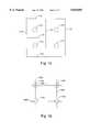
- FIG. 1ais a diagrammatic illustration of one cutting pattern for arrhythmia circuits. This particular cutting pattern is well-suited for use in cutting arrhythmia circuits formed around pulmonary veins. That is, this cutting pattern may be used in atrial fibrillation applications.
- FIG. 1ashows cross-sections of pulmonary veins 110. It should be appreciated that the orientation of pulmonary veins 110 as shown is exaggerated for illustrative purposes.
- Arrhythmia circuits(not shown), or connections, may form between pulmonary veins 110. In order to eliminate the circuits, thereby eliminating unwanted, or abnormal, electrical connections in the heart, circuits between pulmonary veins 110 may be cut.
- cutting-lines 116, 118may be formed between and around pulmonary veins 110 in order to cut circuits formed between pulmonary veins 110.
- These cutting-lines 116, 118are essentially lesions which disrupt arrhythmia circuits formed within the atria of the heart.
- cutting-lines 116, 118form linear lesions.
- cutting-lines 116, 118may not necessarily form linear lesions.
- cutting-lines 116are formed orthogonally to cutting-lines 118, although cutting-lines formed between and around pulmonary veins 110 may take on any suitable orientation.
- FIG. 1bis a diagrammatic illustration of a second cutting pattern for arrhythmia circuits. As shown, FIG. 1b illustrates a second cutting pattern which may be used to cut arrhythmia circuits formed around pulmonary veins for atrial fibrillation applications.
- Cross-sections of pulmonary veins 110are shown with cutting-lines 126, 130 formed between adjacent pulmonary veins 110.
- cutting-line, or lesion, 126ais formed between adjacent pulmonary veins 110a and 110b.
- cutting-line 130ais formed between adjacent pulmonary veins 110a and 110c.
- cutting-lines 126, 130have been drawn "through" pulmonary veins 110, the pulmonary veins 110 are not actually cut through. Rather, the arrhythmia circuits (not shown) formed between pulmonary veins 110 are cut through.
- the catheter tipmust often be removed from a person's body in order to straighten the catheter tip.
- the process of constantly removing and reinserting a catheter into a person's body during an ablation procedureis inefficient, time-consuming, and painful. Therefore, it would be desirable to have a catheter tip which does not generally require the removal of the catheter tip from the human body for straightening purposes. That is, what is desired is a self-straightening catheter tip.
- a conformally positionable ablation catheterincludes an elongated flexible tubular member adapted to be inserted into a vessel in the body of a patient.
- a transmission lineis disposed within the tubular member and a transducer is coupled to the transmission line for generating an electric field sufficiently strong to cause tissue ablation.
- a shape memory wireis positioned at a distal portion of the catheter adjacent the transducer to facilitate straightening the catheter tip after use.
- the shape memory wiremay be a flat wire which is formed from a chromium alloy, a molybdenum alloy, or nickel titanium.
- the transmission line of the catheteris a co-axial cable
- the transduceris a helical antenna coil that is adapted to radiate electromagnetic energy in the microwave frequency range.
- the shape memory wireis positioned within the antenna coil.
- a method for manufacturing a conformally positionable catheterinvolves attaching an antenna coil to a transmission line and inserting a shape memory metal through the antenna coil such that the shape memory metal extends longitudinally within the antenna coil.
- the antenna coilis then filled with a first dielectric material in a first molding operation.
- Positioning ribswhich are used to orient the filled antenna coil in a mold which is used to encapsulate the filled antenna coil with a second dielectric material, may be created with the first dielectric material such that the positioning ribs are aligned along the longitudinal axis of the antenna coil.
- the method for manufacturing a conformally positionable catheterfurther involves inserting sensor leads through the antenna coil along the longitudinal axis of the antenna coil and creating an extension plug at the distal end of the antenna coil using the first dielectric material.
- sensors attached to the sensor leadsare mounted over the extension plug.
- a method for medical treatment using an ablation catheter systemthat includes a catheter tip with a transmission line, a transducer, and a shape memory wire which defines a neutral orientation for the catheter tip involves introducing the catheter into a patient's body such that a distal portion of the catheter is positioned in a cardiac chamber. Once the catheter is positioned, the tip portion of the catheter is substantially conformed to a wall of the chamber. Electromagnetic energy may then be applied to the transmission line to cause ablation of cardiac tissue. The catheter tip is repositioned and cardiac tissue is ablated as required. When the catheter tip is repositioned, the shape memory metal causes the catheter to return substantially to the neutral orientation. Partially withdrawing the catheter from the patient's body also causes the catheter to return substantially to the neutral orientation, while further introducing the catheter into the patient's body causes the catheter to further conform to the wall of the chamber.
- the method for medical treatmentmay also include monitoring electro-physiological signals using catheter electrodes, determining an appropriate ablation position based at least in part on the monitored electro-physiological signals, and positioning the transducer at the determined appropriate ablation position.
- microwave energyis applied to the transmission line to cause the ablation.
- FIG. 1ais a diagrammatic illustration of one cutting pattern for circuits around pulmonary veins.
- FIG. 1bis a diagrammatic illustration of another cutting pattern for circuits around pulmonary veins.
- FIG. 2ais a diagrammatic longitudinal cross-sectional view of a conformally positionable ablation catheter tip in accordance with an embodiment of the present invention.
- FIG. 2bis a diagrammatic cross-sectional view of the conformally positionable ablation catheter tip of FIG. 2a.
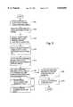
- FIG. 3is a flow chart which illustrates steps in a process for manufacturing a conformally positionable ablation catheter in accordance with an embodiment of the present invention.
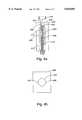
- FIG. 4ais a diagrammatic cross-sectional view of an initial mold used to position an antenna assembly during a first molding operation in accordance with an embodiment of the present invention.
- FIG. 4bis a diagrammatic top view of the mold as shown in FIG. 4b.
- FIG. 5ais a diagrammatic cross-sectional axial view of a conformally positionable antenna assembly after a first molding process in accordance with an embodiment of the present invention.
- FIG. 5bis a diagrammatic longitudinal side view of the conformally positionable antenna assembly of FIG. 5a.
- FIG. 6is a diagrammatic top view of a second mold used to create a desired tip diameter for an ablation catheter in accordance with an embodiment of the present invention.
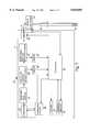
- FIG. 7is a diagrammatic illustration of a microwave ablation catheter system in accordance with an embodiment of the present invention.
- a conformally positionable microwave ablation catheter systemis capable of conforming to a surface, as for example a wall of a cardiac chamber.
- a shape memory wirepositioned at a distal portion, i.e. catheter tip, of the catheter enables the catheter to reconform to the wall of the cardiac chamber without the need for removing the catheter tip from a patient's body for straightening.
- the shape memory wirefacilitates the straightening of the catheter tip.
- a conformally positionable ablation catheter 200generally includes an antenna 206 with a proximal end 208 and a distal end 210.
- Proximal end 208 of antenna 206is grounded to a shield (not shown) of transmission line 220.
- transmission line 220which is supported within a distal shaft 222, is typically co-axial, and coupled to a power supply, shown in FIG. 7, which is external to catheter 200.
- Distal end 210 of antenna 206is attached to center conductor 224 of transmission line 220.
- antenna 206is in the form of a coil, i.e.
- antenna coil 206which is made from any suitable material, such as spring steel, beryllium copper, or silver-plated copper.
- the outer diameter of antenna coil 206will vary to some extent based on the particular application of the catheter.
- a catheter suitable for use in an atrial fibrillation applicationmay have typical coil outer diameters in the range of approximately 0.07 to 0.1 inches. More preferably, the outer diameter of antenna coil 206 may be in the range of approximately 0.08 to 0.09 inches.
- shape memory metal wire 228,is axially located within antenna, or antenna coil, 206.
- shape memory metal wire 228may be positioned such that longitudinal axes of both antenna 206 and shape memory metal wire 228 are aligned.
- Shape memory metal wire 228, which is typically a flat wire,may be made from any suitable shape memory metal. The shape of shape memory metal 228 is dependent upon the desired positioning attributes of catheter 200.
- a shape memory metalis a moldable metal which has a "default,” or rest, state. This default state may also be considered to be a neutral state.
- a shape memory metalis generally a metal which may be shaped when force is applied to the metal.
- the shape memory metalmay be any suitable "elastic" metal.
- nickel titanium, copper beryllium, and steel alloyshave been observed to work well.
- the typical shape of shape memory metal wire 228is a flat shape, e.g. it has a rectangular cross-section where the height of the rectangle is much greater than the width of the rectangle.
- a flat shapemay be considered to be any shape in which the average height of the shape is significantly greater than the average width of the shape.
- a flat-shaped shape memory metal wire 228is preferred due to the fact that a flat-shaped shape memory metal wire 228 will have the tendency to bend at one axis, or in one plane. Hence, a flat-shaped shape memory metal wire 228 is easier to control, and, therefore, easier to steer since the flat-shaped shape memory metal wire 228 will not exhibit significant bending in more than one plane.
- flat cross-sectional shapesare preferred for shape memory metal wire 228, other shapes such as conventional round wires will also work in many applications.
- sensor conduit 252shown in FIG. 2b (shown in more detail in FIG. 5b), which carries sensor wires 250, shown in FIG. 2b, is generally located along the longitudinal axis of catheter tip 200.
- sensor conduit 252 which carries sensor wires 250is typically axially located within antenna coil 206.
- the term "axially located”refers to sensor conduit 252 being located such that is parallel to the longitudinal axis of antenna coil 206.
- the sensor wiresare connected with distal electrodes 230 which are provided as part of catheter 200 to facilitate positioning of catheter 200 during use.
- Distal electrodes 230are used to detect electro-physiological signals from cardiac tissue and, hence, may be used to map the relevant region of the heart prior to or after an ablation procedure. Distal electrodes 230 may also be used to aid in positioning catheter 200 during the ablation procedure. Distal electrodes 230 may be made from a variety of biocompatible materials, which include stainless steel or iridium platinum. Like distal electrodes 230, proximal electrodes 234, which are typically formed from the same biocompatible materials as distal electrodes 230, may also be used for positioning purposes and to map regions of the heart prior to or after an ablation procedure.
- the distal tip 236 of catheter 200which includes the elongated tube portion 238 of catheter 200, i.e. the section of catheter 200 which encapsulates antenna 206, may be formed from a flexible dielectric material. That is, the material which both fills and surrounds antenna coil 206 is typically a flexible dielectric material. Suitable flexible dielectric materials include, but are not limited to, materials such as silicone.
- GE Liquid Injection Material (LIM) 6040 through 6070a silicone family from General Electric in Waterford, N.Y.
- LIMLiquid Injection Material
- a flexible tubular memberis usually placed or formed over transmission line 220 in a conventional manner.
- the flexible tubular membermay be made from any suitable material including, but not limited to, medical grade polyolefins, fluoropolymers, or polyvinylidene fluoride.
- PEBAX resinsfrom Autochem of Germany have been used with success.
- catheter 200In general, the dimensions of catheter 200 are dependent upon the requirements of a particular application for the catheter. However, a catheter tip diameter, e.g. the diameter of elongated tube portion 238, in the range of approximately 7 to 9 French, or approximately 0.092 to 0.141 inches, has been observed to work well for most cardiac applications. It is generally desired that the catheter tip diameter exceed the diameter of the antenna coil, in order to properly encapsulate the antenna coil. By way of example, excess catheter tip diameters in the range of approximately 0.005 to 0.015 inches, as for example approximately 0.01 inches, more than the diameter of the antenna coil work well. A catheter tip length in the range of approximately 0.2 to 2.5 inches is preferable. More preferably, a catheter tip length is in the range of approximately 1.2 to 2 inches. The catheter tip length varies as a result of any number of factors which include, but are not limited to, the particular requirements of the application and the size of a patient's heart.
- a catheter tip diametere.g. the diameter of elongated tube portion 238,
- the cathetermay be fed through the femoral artery or any other suitable vessel and into the appropriate region of the heart.
- the catheter tipwhich is the distal tip of the catheter, is typically fed into the appropriate atrial chamber.
- the conformally positionable ablation catheter as described with respect to FIG. 2amay be passively steered. That is, once the tip of the catheter is positioned in proximity of a desired position in a chamber of the heart using standard steering methods which are well known in the art, the catheter tip may be rotated such that it may reach the desired position.
- a flat shape memory metal wiremay bend significantly only along one axis, or in one plane.
- the cathetermay have to be rotated such that the "bending-axis" is properly oriented to facilitate the conforming of the catheter tip to the wall of the heart chamber.
- a rotation of the catheter tip and the application of forcewill generally enable the catheter tip to conform to the wall of the heart chamber.
- any suitable methodmay be used to apply force to the catheter tip and, hence, the shape memory metal within the catheter tip.
- One method which may be used to apply force to the catheter tipmay entail applying a force by "pushing” or pressing the catheter tip further against the wall of the heart chamber.
- the shape memory metalconforms, along with the catheter tip, to the wall of the heart chamber.
- the electrodescan detect electrical signals or, more specifically, electro-physiological signals, in the adjacent regions of the heart. If necessary, the catheter may be further inserted, and or withdrawn to facilitate a mapping of the region of interest. Typically, mapping will indicate the location at which relevant electro-physiological signals, or cardiac signals, as for example EKGs, are strongest. This, in turn, will permit a physician to determine the appropriate ablation position.
- the catheteris then positioned as necessary to locate the antenna properly for the ablating procedure. After the antenna is properly positioned, microwave energy is applied to the co-axial transmission line to facilitate the ablation. During the ablation procedure, as well as after the operation is completed, the electrodes may be used to monitor the ablation process as well as the results.
- a suitable microwave generatorwill be described below with reference to FIG. 7.
- the force pressing the catheter against the heart wallmay be at least partially released to enable the catheter to be moved. At least partially releasing the force pressing the catheter against the heart wall also releases at least some of the force on the shape memory metal within the catheter tip. An almost complete removal of force from the catheter tip will enable the shape memory metal and, hence, the catheter tip to return to their original, default shapes. That is, the shape memory metal will return to the state it was in prior to the application of force.
- an antennais attached to the center conductor and the shield of a co-axial cable.
- the co-axial cableis a co-axial transmission line.
- the distal end of the antennais connected with the center conductor, while the proximal end of the antenna is grounded to the shield.
- the antennamay be formed from any suitable material, as for example silver plated copper wire or beryllium copper wire.
- the antennais generally an antenna coil. In the illustrated embodiments, the antenna coil is helically wound.
- a piece of shape memory metalis insulated with heat shrink tubing in step 308 in order to prevent the shape memory metal from shorting against the antenna.
- the heat shrink tubingis heated and shrunk so that it tightly covers the shape memory metal.
- the shape memory metalmay be any suitable "elastic" metal, as for example nickel titanium, a chromium alloy, or a molybdenum alloy.
- the shape memory metalis typically elongated with a flat, e.g. rectangular, cross-section, it should be appreciated that the shape memory may take on any number of shapes.
- the shape memory metalmay have a round cross-section.
- a shape memory metal with a flat cross-sectionis generally preferred, as such a shape memory metal has the tendency to bend in only one direction, i.e. along a single axis, whereas a shape memory metal with a round cross-section may bend in any number of directions.
- the insulated shape memory metal and a sensor conduitare axially inserted through the antenna coil. That is, the shape memory metal and the sensor conduit are inserted through the antenna coil along the longitudinal axis of the antenna coil.
- the sensor conduitwhich is designed to house sensor leads, may be a polyimide tube.
- the antenna coil, the sensor conduit with the sensor leads, and the shape memory metal, which together comprise an antenna assembly,are placed in a first mold in step 314.
- the first moldis generally used to concentrically position the sensor conduit and shape memory metal relative to the antenna coil and to facilitate the creation of positioning ribs along the perimeter of the antenna coil.
- the first moldwhich will be described in more detail below with reference to FIGS. 4a and 4b, has a cavity 404 which supports the antenna coil 412 and, therefore, enables the antenna coil 412 to be filled with a dielectric material.
- the cavity 404has a diameter which is substantially equal to the diameter of the antenna coil 412, and is therefore able to support the antenna coil 412 while it is within the cavity 404.
- the antenna assembly 410is positioned in the first mold 400 such that the sensor leads 414 extend through the first mold 400.
- a first injection molding operationis performed to fill the center of the antenna coil 412 and to create positioning ribs and an extension plug around the antenna coil 412. That is, a first injection molding operation is essentially used to partially encapsulate and fill the antenna assembly 410.
- the partially encapsulated antenna assembly 410will be described below with respect to FIGS. 5a and 5b.
- the positioning ribs 510are formed along the perimeter of the antenna assembly 406 such that the distance from the edge of one positioning rib, as for example edge 512a positioning rib 510a, to the edge of a directly opposing positioning rib, as for example edge 512c of positioning rib 510c, is equal to the desired, final outer diameter of the completed antenna assembly.
- the first injection molding operationmay be performed using any suitable pliant material including, but not limited to, silicone.
- siliconeIn addition to being flexible when it is cured, silicone is not self-heating, which is a desirable characteristic for a material used in the fabrication of a catheter.
- GE Liquid Injection Material (LIM) 6040a silicone from General Electric in Waterford, N.Y.
- a distal electrode 538is generally a band.
- the distal electrodes 538may be annular bands which may be cut into segments after they are mounted, i.e. installed, or the distal electrodes 538 may be independent segments that form associated bands only after installation.
- the distal electrodes 538are connected to the specific sensor, or electrode, leads 537 with which they are associated, thereby forming an electrode ring assembly having the desired number of electrode wires, such as a pair of electrode wires, which may then be slid over the antenna assembly and positioned in its desired location.
- heat shrink tubingis then heated and shrunk over the distal electrodes 538 such that the heat shrink tubing tightly covers the electrodes 538 and seals electrode wire holes through which the sensor wires 537 pass.
- the distal electrodes 538may be covered with ultraviolet (UV) curable epoxy which is then cured to set the electrodes 538.
- UVultraviolet
- the electrodes 538are provided to facilitate positioning of the catheter 502 during use.
- the electrodes 538are used to detect electro-physiological signals from cardiac tissue and may therefore be used to map the relevant region of the heart prior to or after an ablation procedure.
- the electrodes 538may also be used to aid in positioning the catheter 502 for use and to monitor the patient's condition during the ablation process.
- electrodes 538may be made from a variety of different biocompatible materials, electrodes 538 are typically made of either stainless steel or iridium platinum.
- step 320the antenna assembly, which, at this point in the process, is partially molded over, is placed in a second mold which is used to set the final outer diameter of the tip of the completed antenna assembly.
- a second moldwhich is used to set the final outer diameter of the tip of the completed antenna assembly.
- the second moldbesides being used to set the final outer diameter of the completed antenna assembly, is used to eliminate any bubbles which may have been formed in the catheter as a result of the first injection molding process. The second mold will be discussed in more detail below with reference to FIG. 6.
- a second injection molding operationis performed in step 322 to create the final desired diameter of the antenna assembly, or more specifically, the final desired tip diameter of the antenna assembly.
- the same material which was used in the first injection molding operationis generally also used for the second injection molding operation, though any suitable material may be used.
- the antenna assembly with the final desired tip diametermay be considered to be a conformal positioning assembly.
- the remaining steps associated with the catheter construction processare performed in step 324. These steps include, but are not limited to, inserting the co-axial cable into a distal shaft, or a flexible tubular member, in a conventional manner.
- the conventional mannerinvolves binding the antenna assembly to the distal end of the flexible tubular member and attaching the handle to the proximal end of the flexible member.
- the flexible tubular membermay be made from any suitable material including, but not limited to, medical grade polyolefins, fluoropolymers, or polyvinylidene fluoride.
- PEBAX resinsfrom Autochem of Germany have been used with success in molding the body of the catheter. Stiffening wires, steering wires, additional sensor wires, etc., may all be included in the final assembly as required by a particular design. After the final assembly is completed, the process of manufacturing a conformally positionable catheter is completed.
- FIG. 4ais a diagrammatic cross-sectional view of a mold used to position an antenna assembly, i.e. an antenna, a shape memory wire, and a sensor conduit which houses sensor wires.
- FIG. 4bis a diagrammatic top view of mold 400 as shown in FIG. 4a. Mold 400, which may be made from any suitable material, has a main cavity 404 in which an antenna assembly 410 is situated.
- Main cavity 404comes into contact with rib cavities 424 which are used to form positioning ribs around antenna assembly 410.
- Main cavity 404is further sized such that edges of main cavity, as for example edges 411, come into contact with antenna assembly 410 and, more specifically, an antenna coil 412. That is, the diameter of main cavity 404 is substantially the same as the diameter of antenna coil 412.
- the shape, or an axial cross-section, of main cavity 404is dependent upon the desired shape, i.e. axial cross-section, of the molded over antenna assembly (not shown).
- the shape of main cavity 404is either circular (as shown) or oval. However, it should be understood that the shape may be widely varied depending upon the requirements of a particular antenna assembly.
- antenna assembly 410also includes a shape memory wire (not shown) and a transmission line 415.
- antenna assembly 410has been generically represented, and the shape memory wire has not been shown in FIG. 4a.
- Sensor wires 414which are attached to an electrode ring 416, extend past the top edge 420 of mold 400.
- antenna assembly 410In order to align the components of antenna assembly 410, i.e. antenna coil 412, sensor conduit 413 with sensor wires 414, the shape memory metal (not shown), the transmission line 415, as required for a particular catheter, mechanisms external to mold 400 may be used to hold and otherwise position antenna assembly 410.
- mold 400is capable of supporting antenna coil 412 for positioning purposes.
- the shape memory metal and the sensor conduitmay suitably be aligned by allowing the shape memory metal and sensor conduit 413 to be held against transmission line 415 within antenna assembly 410.
- mold 400is implemented to fill the center of antenna coil 412 as well as to create positioning ribs and an extension plug around antenna assembly 410.
- the positioning ribsare formed using rib cavities 424, while the extension plug is generally formed on antenna assembly 410 near top edge 420 of mold 400 in the top portion 430 of main cavity 404.
- the extension plugis formed to provide a surface over which electrode ring 416 may be mounted.
- the diameter of the extension plug after the first molding operationwill generally be the equal to the diameter of main cavity 404.
- mold 400may be comprised of at least two distinct pieces which may be interconnected during the molding process, and separated after the molding process in order to remove antenna assembly 410 from mold 400.
- main cavity 404extends approximately the length of mold 400, while rib cavities 424 extend less than the length of mold 400.
- the relative depths, or more generally, dimensions of main cavity 400 and rib cavities 424may vary greatly depending upon the requirements of a specific antenna assembly.
- FIG. 5aa diagrammatic cross-sectional axial view of a partially molded conformally positionable antenna assembly after a first molding process in accordance with an embodiment of the present invention will be described.
- the cross-sectional viewis shown without an antenna coil, a sensor conduit, a shape memory wire and transmission line for illustrative purposes. That is, only the "outline" of conformally positionable antenna assembly 502 is shown for ease of illustration. Further, the cross-section of antenna assembly 502 that is shown is away from the extension plug formed at the distal end of antenna assembly 502.
- the "main body” 506 of antenna assemblywhich is comprised of any suitable malleable material, as for example silicone as described above, encapsulates the antenna coil, sensor conduit, shape memory wire, etc. Although main body 506 may have any cross-sectional shape, in the embodiment as shown, main body 506 has a circular cross-section. Positioning ribs 510, which are used to position antenna assembly 502 within a second mold used to complete the antenna tip assembly as will be described below with reference to FIG. 6, are formed along the perimeter of main body 506, and are made of the same material as main body 506.
- the tip-to-tip distance D from the tip of a first positioning rib, as for example positioning rib 510a with tip 512a, to the tip of a second positioning rib which is directly opposite the first positioning rib, as for example positioning rib 510c with tip 512c,is generally approximately equal to the desired diameter of the completed antenna tip (not shown).
- Positioning ribs 510may take on any suitable cross-section. However, positioning ribs 510 which have curved, e.g. semi-circular, axial cross-sections are preferable due to the fact that the final antenna tip assembly has a round cross-section. That is, the completed catheter assembly has a round cross-section. Hence, positioning ribs 510 have curved cross-sections for ease of manufacturability. As will be appreciated by those skilled in the art, utilizing positioning ribs 510 with axial cross-sections which are rectangular, for example, would have the tendency to require an end mill to "shave" the edges of the rectangle in order to achieve the desired diameter of the completed antenna tip.
- positioning ribs 510may be used, in the described embodiment, four positioning ribs 510 which are symmetrical about the perimeter of main body 506 are shown. This number and orientation of positioning ribs 510 have been shown to be effective in securely positioning antenna assembly 502 within the aforementioned second mold.
- Each positioning ribas for example positioning rib 510a, has a "height," i.e. tip-to-base dimension, d in the range of approximately 0.005 to 0.01 inches, as for example approximately 0.007 inches.
- FIG. 5ba diagrammatic longitudinal side view of the partially molded conformally positionable antenna assembly of FIG. 5a.
- Antenna assembly 502includes main body 506, an extension plug 520 formed at the distal end of antenna assembly 502, and positioning ribs 512. It should be appreciated that only two positioning ribs, i.e. positioning ribs 510a and 510c, have been shown for ease of illustration.
- Antenna assembly 530includes, as previously described, an antenna coil 530, a sensor conduit 536, and a shape memory metal 542. Antenna coil 530 is coupled at a proximal end to the shield 532 of co-axial cable, or transmission line, 533 which effectively serves to ground antenna coil 530.
- antenna coil 530is coupled to the center conductor 534 of co-axial cable 533.
- Sensor conduit 536houses sensor wires 537 which are coupled to an electrode 538. Electrode 538, as shown, has not yet been mounted over extension plug 520. Although only one electrode 538 has been shown, it should be appreciated that the number of electrodes coupled to sensor wires 537, as well as the number of sensor wires 537, is dependent upon the requirements of a particular catheter.
- FIG. 6is a diagrammatic top view of the mold used to create a desired tip diameter for a catheter in accordance with an embodiment of the present invention.
- Mold 602is used primarily to create the desired tip diameter for a conformally positionable catheter.
- Mold 602includes cavity 606 which holds the antenna assembly 610, as previously described with respect to FIGS. 5a and 5b, after the distal electrode of the antenna assembly has been properly mounted over the extension plug.
- Antenna assembly 610will fit into cavity 606, prior to the second injection molding process, substantially as shown.
- As the tip-to-tip distance between positioning ribs 616is approximately equal to the final diameter of the catheter tip formed using mold 602, positioning ribs 616 is shown to be flush with the edges 620 of cavity 606.
- FIG. 7is a diagrammatic illustration of a microwave ablation catheter system in accordance with an embodiment of the present invention.
- An ablation catheter system 10generally includes a power supply 20 which is designed to generate controlled electromagnetic energy, a catheter 50 which is designed for insertion into a vessel (such as a coronary vessel) in the body of a patient and a connector 71 for coupling the power supply 20 to the catheter 50.
- the cathetertypically includes a flexible outer tubing, a co-axial microwave transmission line that extends through the flexible tubing, and an antenna 56 coupled to the distal end of the co-axial transmission line.
- the connectorcouples transmission line 53 to external power supply 20.
- a handle 73may be provided for use by the surgeon to facilitate steering and potentially other control functions.
- catheter 50may include a variety of sensors for monitoring the patient during insertion, positioning and/or use of the catheter.
- sensorsmay include a plurality of mapping electrodes 230, as shown in FIG. 2a, and one or more thermocouple wires (not shown).
- the co-axial microwave transmission line 53includes a center conductor, a shield, and a dielectric material disposed between the center conductor and shield.
Landscapes
- Health & Medical Sciences (AREA)
- Life Sciences & Earth Sciences (AREA)
- Surgery (AREA)
- Engineering & Computer Science (AREA)
- Veterinary Medicine (AREA)
- Public Health (AREA)
- Nuclear Medicine, Radiotherapy & Molecular Imaging (AREA)
- General Health & Medical Sciences (AREA)
- Biomedical Technology (AREA)
- Animal Behavior & Ethology (AREA)
- Medical Informatics (AREA)
- Molecular Biology (AREA)
- Heart & Thoracic Surgery (AREA)
- Otolaryngology (AREA)
- Physics & Mathematics (AREA)
- Electromagnetism (AREA)
- Cardiology (AREA)
- Plasma & Fusion (AREA)
- Radiology & Medical Imaging (AREA)
- Surgical Instruments (AREA)
Abstract
Description
Claims (18)
Priority Applications (2)
| Application Number | Priority Date | Filing Date | Title |
|---|---|---|---|
| US08/732,045US5810803A (en) | 1996-10-16 | 1996-10-16 | Conformal positioning assembly for microwave ablation catheter |
| US08/755,998US5741249A (en) | 1996-10-16 | 1996-11-25 | Anchoring tip assembly for microwave ablation catheter |
Applications Claiming Priority (2)
| Application Number | Priority Date | Filing Date | Title |
|---|---|---|---|
| US08/732,045US5810803A (en) | 1996-10-16 | 1996-10-16 | Conformal positioning assembly for microwave ablation catheter |
| US08/755,998US5741249A (en) | 1996-10-16 | 1996-11-25 | Anchoring tip assembly for microwave ablation catheter |
Publications (1)
| Publication Number | Publication Date |
|---|---|
| US5810803Atrue US5810803A (en) | 1998-09-22 |
Family
ID=46252276
Family Applications (1)
| Application Number | Title | Priority Date | Filing Date |
|---|---|---|---|
| US08/732,045Expired - Fee RelatedUS5810803A (en) | 1996-10-16 | 1996-10-16 | Conformal positioning assembly for microwave ablation catheter |
Country Status (1)
| Country | Link |
|---|---|
| US (1) | US5810803A (en) |
Cited By (139)
| Publication number | Priority date | Publication date | Assignee | Title |
|---|---|---|---|---|
| US6030382A (en)* | 1994-08-08 | 2000-02-29 | Ep Technologies, Inc. | Flexible tissue ablatin elements for making long lesions |
| RU2209096C1 (en)* | 2002-01-23 | 2003-07-27 | Саратовский научно-исследовательский институт травматологии и ортопедии | Device for applying electromagnetic therapy |
| GB2388039A (en)* | 1999-02-25 | 2003-11-05 | Microsulis Ltd | Radiation Applicator |
| US6823218B2 (en)* | 1999-05-28 | 2004-11-23 | Afx, Inc. | Monopole tip for ablation catheter and methods for using same |
| GB2406521A (en)* | 2003-10-03 | 2005-04-06 | Microsulis Ltd | Microwave applicator for treating varicose veins |
| WO2005034783A1 (en) | 2003-10-03 | 2005-04-21 | Microsulis Limited | Device and method for the treatment of hollow anatomical structures |
| US6976986B2 (en) | 2000-04-12 | 2005-12-20 | Afx, Inc. | Electrode arrangement for use in a medical instrument |
| US7033352B1 (en) | 2000-01-18 | 2006-04-25 | Afx, Inc. | Flexible ablation instrument |
| US7052491B2 (en) | 1998-10-23 | 2006-05-30 | Afx, Inc. | Vacuum-assisted securing apparatus for a microwave ablation instrument |
| US20060147245A1 (en)* | 2004-12-30 | 2006-07-06 | Carl Cetera | Implement grip |
| US20060155270A1 (en)* | 2002-11-27 | 2006-07-13 | Hancock Christopher P | Tissue ablation apparatus and method of ablating tissue |
| US7099717B2 (en) | 2002-01-03 | 2006-08-29 | Afx Inc. | Catheter having improved steering |
| US20060258937A1 (en)* | 2005-05-12 | 2006-11-16 | Daane Laurence A | Catheter with compactly terminated electronic component |
| US20060276781A1 (en)* | 2004-04-29 | 2006-12-07 | Van Der Weide Daniel W | Cannula cooling and positioning device |
| US7192427B2 (en) | 2002-02-19 | 2007-03-20 | Afx, Inc. | Apparatus and method for assessing transmurality of a tissue ablation |
| US7226446B1 (en) | 1999-05-04 | 2007-06-05 | Dinesh Mody | Surgical microwave ablation assembly |
| US7303560B2 (en) | 2000-12-29 | 2007-12-04 | Afx, Inc. | Method of positioning a medical instrument |
| US20070288079A1 (en)* | 2006-03-24 | 2007-12-13 | Micrablate | Energy delivery system and uses thereof |
| US20080234574A1 (en)* | 2004-05-26 | 2008-09-25 | Medical Device Innovations Limited | Tissue Detection and Ablation Apparatus and Apparatus and Method For Actuating a Tuner |
| US7467015B2 (en) | 2004-04-29 | 2008-12-16 | Neuwave Medical, Inc. | Segmented catheter for tissue ablation |
| US20090183895A1 (en)* | 2008-01-23 | 2009-07-23 | Vivant Medical, Inc. | Thermally Tuned Coaxial Cable for Microwave Antennas |
| US20090247990A1 (en)* | 2008-03-28 | 2009-10-01 | Uresil, Llc | Locking medical catheter |
| US7799019B2 (en) | 2005-05-10 | 2010-09-21 | Vivant Medical, Inc. | Reinforced high strength microwave antenna |
| US7862559B2 (en) | 2001-11-02 | 2011-01-04 | Vivant Medical, Inc. | High-strength microwave antenna assemblies and methods of use |
| WO2011017168A2 (en) | 2009-07-28 | 2011-02-10 | Neuwave Medical, Inc. | Energy delivery systems and uses thereof |
| US7998139B2 (en) | 2007-04-25 | 2011-08-16 | Vivant Medical, Inc. | Cooled helical antenna for microwave ablation |
| US20110213351A1 (en)* | 2010-02-26 | 2011-09-01 | Lee Anthony C | Self-Tuning Microwave Ablation Probe |
| US8353901B2 (en) | 2007-05-22 | 2013-01-15 | Vivant Medical, Inc. | Energy delivery conduits for use with electrosurgical devices |
| US8568404B2 (en) | 2010-02-19 | 2013-10-29 | Covidien Lp | Bipolar electrode probe for ablation monitoring |
| US8617153B2 (en) | 2010-02-26 | 2013-12-31 | Covidien Lp | Tunable microwave ablation probe |
| US8651146B2 (en) | 2007-09-28 | 2014-02-18 | Covidien Lp | Cable stand-off |
| US8672932B2 (en) | 2006-03-24 | 2014-03-18 | Neuwave Medical, Inc. | Center fed dipole for use with tissue ablation systems, devices and methods |
| US8740893B2 (en) | 2010-06-30 | 2014-06-03 | Covidien Lp | Adjustable tuning of a dielectrically loaded loop antenna |
| US8880185B2 (en) | 2010-06-11 | 2014-11-04 | Boston Scientific Scimed, Inc. | Renal denervation and stimulation employing wireless vascular energy transfer arrangement |
| US8882759B2 (en) | 2009-12-18 | 2014-11-11 | Covidien Lp | Microwave ablation system with dielectric temperature probe |
| US8939970B2 (en) | 2004-09-10 | 2015-01-27 | Vessix Vascular, Inc. | Tuned RF energy and electrical tissue characterization for selective treatment of target tissues |
| US8951251B2 (en) | 2011-11-08 | 2015-02-10 | Boston Scientific Scimed, Inc. | Ostial renal nerve ablation |
| US8974451B2 (en) | 2010-10-25 | 2015-03-10 | Boston Scientific Scimed, Inc. | Renal nerve ablation using conductive fluid jet and RF energy |
| US9023024B2 (en) | 2007-06-20 | 2015-05-05 | Covidien Lp | Reflective power monitoring for microwave applications |
| US9023034B2 (en) | 2010-11-22 | 2015-05-05 | Boston Scientific Scimed, Inc. | Renal ablation electrode with force-activatable conduction apparatus |
| US9028472B2 (en) | 2011-12-23 | 2015-05-12 | Vessix Vascular, Inc. | Methods and apparatuses for remodeling tissue of or adjacent to a body passage |
| US9028485B2 (en) | 2010-11-15 | 2015-05-12 | Boston Scientific Scimed, Inc. | Self-expanding cooling electrode for renal nerve ablation |
| US9050106B2 (en) | 2011-12-29 | 2015-06-09 | Boston Scientific Scimed, Inc. | Off-wall electrode device and methods for nerve modulation |
| US9060761B2 (en) | 2010-11-18 | 2015-06-23 | Boston Scientific Scime, Inc. | Catheter-focused magnetic field induced renal nerve ablation |
| US9079006B1 (en) | 2008-03-28 | 2015-07-14 | Uresil, Llc | Suture locking mechanism |
| US9079000B2 (en) | 2011-10-18 | 2015-07-14 | Boston Scientific Scimed, Inc. | Integrated crossing balloon catheter |
| US9084609B2 (en) | 2010-07-30 | 2015-07-21 | Boston Scientific Scime, Inc. | Spiral balloon catheter for renal nerve ablation |
| US9089350B2 (en) | 2010-11-16 | 2015-07-28 | Boston Scientific Scimed, Inc. | Renal denervation catheter with RF electrode and integral contrast dye injection arrangement |
| US9119600B2 (en) | 2011-11-15 | 2015-09-01 | Boston Scientific Scimed, Inc. | Device and methods for renal nerve modulation monitoring |
| US9119632B2 (en) | 2011-11-21 | 2015-09-01 | Boston Scientific Scimed, Inc. | Deflectable renal nerve ablation catheter |
| US9125666B2 (en) | 2003-09-12 | 2015-09-08 | Vessix Vascular, Inc. | Selectable eccentric remodeling and/or ablation of atherosclerotic material |
| US9125667B2 (en) | 2004-09-10 | 2015-09-08 | Vessix Vascular, Inc. | System for inducing desirable temperature effects on body tissue |
| US9131836B2 (en) | 2011-08-25 | 2015-09-15 | Covidien Lp | Transmitting torque to an operative element through a working channel |
| US9155589B2 (en) | 2010-07-30 | 2015-10-13 | Boston Scientific Scimed, Inc. | Sequential activation RF electrode set for renal nerve ablation |
| US9162046B2 (en) | 2011-10-18 | 2015-10-20 | Boston Scientific Scimed, Inc. | Deflectable medical devices |
| US9173696B2 (en) | 2012-09-17 | 2015-11-03 | Boston Scientific Scimed, Inc. | Self-positioning electrode system and method for renal nerve modulation |
| US9186209B2 (en) | 2011-07-22 | 2015-11-17 | Boston Scientific Scimed, Inc. | Nerve modulation system having helical guide |
| US9186210B2 (en) | 2011-10-10 | 2015-11-17 | Boston Scientific Scimed, Inc. | Medical devices including ablation electrodes |
| US9192435B2 (en) | 2010-11-22 | 2015-11-24 | Boston Scientific Scimed, Inc. | Renal denervation catheter with cooled RF electrode |
| US9192790B2 (en) | 2010-04-14 | 2015-11-24 | Boston Scientific Scimed, Inc. | Focused ultrasonic renal denervation |
| US9192438B2 (en) | 2011-12-21 | 2015-11-24 | Neuwave Medical, Inc. | Energy delivery systems and uses thereof |
| US20150366612A1 (en)* | 2014-06-20 | 2015-12-24 | Perseon Corporation | Ablation emitter assembly |
| US9220558B2 (en) | 2010-10-27 | 2015-12-29 | Boston Scientific Scimed, Inc. | RF renal denervation catheter with multiple independent electrodes |
| US9220561B2 (en) | 2011-01-19 | 2015-12-29 | Boston Scientific Scimed, Inc. | Guide-compatible large-electrode catheter for renal nerve ablation with reduced arterial injury |
| US9265969B2 (en) | 2011-12-21 | 2016-02-23 | Cardiac Pacemakers, Inc. | Methods for modulating cell function |
| US9277955B2 (en) | 2010-04-09 | 2016-03-08 | Vessix Vascular, Inc. | Power generating and control apparatus for the treatment of tissue |
| US9297845B2 (en) | 2013-03-15 | 2016-03-29 | Boston Scientific Scimed, Inc. | Medical devices and methods for treatment of hypertension that utilize impedance compensation |
| US9326751B2 (en) | 2010-11-17 | 2016-05-03 | Boston Scientific Scimed, Inc. | Catheter guidance of external energy for renal denervation |
| US9327100B2 (en) | 2008-11-14 | 2016-05-03 | Vessix Vascular, Inc. | Selective drug delivery in a lumen |
| US9358365B2 (en) | 2010-07-30 | 2016-06-07 | Boston Scientific Scimed, Inc. | Precision electrode movement control for renal nerve ablation |
| US9364284B2 (en) | 2011-10-12 | 2016-06-14 | Boston Scientific Scimed, Inc. | Method of making an off-wall spacer cage |
| US9408661B2 (en) | 2010-07-30 | 2016-08-09 | Patrick A. Haverkost | RF electrodes on multiple flexible wires for renal nerve ablation |
| US9420955B2 (en) | 2011-10-11 | 2016-08-23 | Boston Scientific Scimed, Inc. | Intravascular temperature monitoring system and method |
| US9433760B2 (en) | 2011-12-28 | 2016-09-06 | Boston Scientific Scimed, Inc. | Device and methods for nerve modulation using a novel ablation catheter with polymeric ablative elements |
| US9463062B2 (en) | 2010-07-30 | 2016-10-11 | Boston Scientific Scimed, Inc. | Cooled conductive balloon RF catheter for renal nerve ablation |
| US9468499B2 (en) | 2003-07-18 | 2016-10-18 | Covidien Lp | Devices and methods for cooling microwave antennas |
| US9486355B2 (en) | 2005-05-03 | 2016-11-08 | Vessix Vascular, Inc. | Selective accumulation of energy with or without knowledge of tissue topography |
| US9549779B2 (en) | 2001-11-02 | 2017-01-24 | Covidien Lp | High-strength microwave antenna assemblies |
| US9579030B2 (en) | 2011-07-20 | 2017-02-28 | Boston Scientific Scimed, Inc. | Percutaneous devices and methods to visualize, target and ablate nerves |
| US9649156B2 (en) | 2010-12-15 | 2017-05-16 | Boston Scientific Scimed, Inc. | Bipolar off-wall electrode device for renal nerve ablation |
| US9668811B2 (en) | 2010-11-16 | 2017-06-06 | Boston Scientific Scimed, Inc. | Minimally invasive access for renal nerve ablation |
| US9687166B2 (en) | 2013-10-14 | 2017-06-27 | Boston Scientific Scimed, Inc. | High resolution cardiac mapping electrode array catheter |
| US9693821B2 (en) | 2013-03-11 | 2017-07-04 | Boston Scientific Scimed, Inc. | Medical devices for modulating nerves |
| US9707036B2 (en) | 2013-06-25 | 2017-07-18 | Boston Scientific Scimed, Inc. | Devices and methods for nerve modulation using localized indifferent electrodes |
| US9713730B2 (en) | 2004-09-10 | 2017-07-25 | Boston Scientific Scimed, Inc. | Apparatus and method for treatment of in-stent restenosis |
| US9770606B2 (en) | 2013-10-15 | 2017-09-26 | Boston Scientific Scimed, Inc. | Ultrasound ablation catheter with cooling infusion and centering basket |
| WO2017180877A2 (en) | 2016-04-15 | 2017-10-19 | Neuwave Medical, Inc. | Systems and methods for energy delivery |
| US9808300B2 (en) | 2006-05-02 | 2017-11-07 | Boston Scientific Scimed, Inc. | Control of arterial smooth muscle tone |
| US9808311B2 (en) | 2013-03-13 | 2017-11-07 | Boston Scientific Scimed, Inc. | Deflectable medical devices |
| US9827039B2 (en) | 2013-03-15 | 2017-11-28 | Boston Scientific Scimed, Inc. | Methods and apparatuses for remodeling tissue of or adjacent to a body passage |
| US9833283B2 (en) | 2013-07-01 | 2017-12-05 | Boston Scientific Scimed, Inc. | Medical devices for renal nerve ablation |
| US9861440B2 (en) | 2010-05-03 | 2018-01-09 | Neuwave Medical, Inc. | Energy delivery systems and uses thereof |
| US9895194B2 (en) | 2013-09-04 | 2018-02-20 | Boston Scientific Scimed, Inc. | Radio frequency (RF) balloon catheter having flushing and cooling capability |
| US9907609B2 (en) | 2014-02-04 | 2018-03-06 | Boston Scientific Scimed, Inc. | Alternative placement of thermal sensors on bipolar electrode |
| US9925001B2 (en) | 2013-07-19 | 2018-03-27 | Boston Scientific Scimed, Inc. | Spiral bipolar electrode renal denervation balloon |
| US9943365B2 (en) | 2013-06-21 | 2018-04-17 | Boston Scientific Scimed, Inc. | Renal denervation balloon catheter with ride along electrode support |
| US9956033B2 (en) | 2013-03-11 | 2018-05-01 | Boston Scientific Scimed, Inc. | Medical devices for modulating nerves |
| US9962223B2 (en) | 2013-10-15 | 2018-05-08 | Boston Scientific Scimed, Inc. | Medical device balloon |
| US9974607B2 (en) | 2006-10-18 | 2018-05-22 | Vessix Vascular, Inc. | Inducing desirable temperature effects on body tissue |
| US10022182B2 (en) | 2013-06-21 | 2018-07-17 | Boston Scientific Scimed, Inc. | Medical devices for renal nerve ablation having rotatable shafts |
| US10058380B2 (en) | 2007-10-05 | 2018-08-28 | Maquet Cordiovascular Llc | Devices and methods for minimally-invasive surgical procedures |
| US10085799B2 (en) | 2011-10-11 | 2018-10-02 | Boston Scientific Scimed, Inc. | Off-wall electrode device and methods for nerve modulation |
| US10182865B2 (en) | 2010-10-25 | 2019-01-22 | Medtronic Ardian Luxembourg S.A.R.L. | Microwave catheter apparatuses, systems, and methods for renal neuromodulation |
| US10265122B2 (en) | 2013-03-15 | 2019-04-23 | Boston Scientific Scimed, Inc. | Nerve ablation devices and related methods of use |
| US10271898B2 (en) | 2013-10-25 | 2019-04-30 | Boston Scientific Scimed, Inc. | Embedded thermocouple in denervation flex circuit |
| US10321946B2 (en) | 2012-08-24 | 2019-06-18 | Boston Scientific Scimed, Inc. | Renal nerve modulation devices with weeping RF ablation balloons |
| US10327845B2 (en)* | 2010-01-25 | 2019-06-25 | Covidien Lp | System and method for monitoring ablation size |
| US10342614B2 (en) | 2004-04-29 | 2019-07-09 | Wisconsin Alumni Research Foundation | Triaxial antenna for microwave tissue ablation |
| US10342609B2 (en) | 2013-07-22 | 2019-07-09 | Boston Scientific Scimed, Inc. | Medical devices for renal nerve ablation |
| WO2019135135A1 (en) | 2018-01-03 | 2019-07-11 | Neuwave Medical, Inc. | Systems and methods for energy delivery |
| US10363092B2 (en) | 2006-03-24 | 2019-07-30 | Neuwave Medical, Inc. | Transmission line with heat transfer ability |
| US10376314B2 (en) | 2006-07-14 | 2019-08-13 | Neuwave Medical, Inc. | Energy delivery systems and uses thereof |
| WO2019159041A1 (en) | 2018-02-15 | 2019-08-22 | Neuwave Medical, Inc. | Compositions and methods for directing endoscopic devices |
| WO2019159040A1 (en) | 2018-02-15 | 2019-08-22 | Neuwave Medical, Inc. | Energy delivery device |
| WO2019162786A1 (en) | 2018-02-26 | 2019-08-29 | Neuwave Medical, Inc. | Energy delivery devices with flexible and adjustable tips |
| US10398464B2 (en) | 2012-09-21 | 2019-09-03 | Boston Scientific Scimed, Inc. | System for nerve modulation and innocuous thermal gradient nerve block |
| US10413357B2 (en) | 2013-07-11 | 2019-09-17 | Boston Scientific Scimed, Inc. | Medical device with stretchable electrode assemblies |
| US10549127B2 (en) | 2012-09-21 | 2020-02-04 | Boston Scientific Scimed, Inc. | Self-cooling ultrasound ablation catheter |
| EP3626194A1 (en) | 2006-07-14 | 2020-03-25 | Neuwave Medical, Inc. | Energy delivery system |
| US10660703B2 (en) | 2012-05-08 | 2020-05-26 | Boston Scientific Scimed, Inc. | Renal nerve modulation devices |
| US10660698B2 (en) | 2013-07-11 | 2020-05-26 | Boston Scientific Scimed, Inc. | Devices and methods for nerve modulation |
| WO2020109999A1 (en) | 2018-11-27 | 2020-06-04 | Neuwave Medical, Inc. | Endoscopic system for energy delivery |
| WO2020121279A1 (en) | 2018-12-13 | 2020-06-18 | Neuwave Medical, Inc. | Energy delivery devices and related systems |
| US10695124B2 (en) | 2013-07-22 | 2020-06-30 | Boston Scientific Scimed, Inc. | Renal nerve ablation catheter having twist balloon |
| US10707581B2 (en) | 2018-01-03 | 2020-07-07 | Wisconsin Alumni Research Foundation | Dipole antenna for microwave ablation |
| US10722300B2 (en) | 2013-08-22 | 2020-07-28 | Boston Scientific Scimed, Inc. | Flexible circuit having improved adhesion to a renal nerve modulation balloon |
| WO2020183262A1 (en) | 2019-03-08 | 2020-09-17 | Neuwave Medical, Inc. | Systems and methods for energy delivery |
| US10835305B2 (en) | 2012-10-10 | 2020-11-17 | Boston Scientific Scimed, Inc. | Renal nerve modulation devices and methods |
| EP3747391A1 (en) | 2015-10-26 | 2020-12-09 | Neuwave Medical, Inc. | Apparatuses for securing a medical device and related methods thereof |
| US10945786B2 (en) | 2013-10-18 | 2021-03-16 | Boston Scientific Scimed, Inc. | Balloon catheters with flexible conducting wires and related methods of use and manufacture |
| US10952792B2 (en) | 2015-10-26 | 2021-03-23 | Neuwave Medical, Inc. | Energy delivery systems and uses thereof |
| US10952790B2 (en) | 2013-09-13 | 2021-03-23 | Boston Scientific Scimed, Inc. | Ablation balloon with vapor deposited cover layer |
| US11000679B2 (en) | 2014-02-04 | 2021-05-11 | Boston Scientific Scimed, Inc. | Balloon protection and rewrapping devices and related methods of use |
| US11202671B2 (en) | 2014-01-06 | 2021-12-21 | Boston Scientific Scimed, Inc. | Tear resistant flex circuit assembly |
| US11246654B2 (en) | 2013-10-14 | 2022-02-15 | Boston Scientific Scimed, Inc. | Flexible renal nerve ablation devices and related methods of use and manufacture |
| US11389235B2 (en) | 2006-07-14 | 2022-07-19 | Neuwave Medical, Inc. | Energy delivery systems and uses thereof |
| WO2023047218A1 (en) | 2021-09-22 | 2023-03-30 | Neuwave Medical, Inc. | Systems and methods for real-time image-based device localization |
| WO2023156965A1 (en) | 2022-02-18 | 2023-08-24 | Neuwave Medical, Inc. | Coupling devices and related systems |
| WO2024176173A1 (en) | 2023-02-24 | 2024-08-29 | Neuwave Medical, Inc. | Temperature regulating devices and related systems and methods |
Citations (38)
| Publication number | Priority date | Publication date | Assignee | Title |
|---|---|---|---|---|
| US4244371A (en)* | 1976-10-13 | 1981-01-13 | Erbe Elektromedizin Gmbh & Co. Kg | High-frequency surgical apparatus |
| US4409993A (en)* | 1980-07-23 | 1983-10-18 | Olympus Optical Co., Ltd. | Endoscope apparatus |
| US4416276A (en)* | 1981-10-26 | 1983-11-22 | Valleylab, Inc. | Adaptive, return electrode monitoring system |
| US4494539A (en)* | 1982-04-03 | 1985-01-22 | Toshio Zenitani | Method and apparatus for surgical operation using microwaves |
| US4601296A (en)* | 1983-10-07 | 1986-07-22 | Yeda Research And Development Co., Ltd. | Hyperthermia apparatus |
| US4641649A (en)* | 1985-10-30 | 1987-02-10 | Rca Corporation | Method and apparatus for high frequency catheter ablation |
| US4657015A (en)* | 1983-02-24 | 1987-04-14 | Werner Irnich | Control device for a high frequency surgical apparatus |
| US4800899A (en)* | 1984-10-22 | 1989-01-31 | Microthermia Technology, Inc. | Apparatus for destroying cells in tumors and the like |
| US4825880A (en)* | 1987-06-19 | 1989-05-02 | The Regents Of The University Of California | Implantable helical coil microwave antenna |
| US4841988A (en)* | 1987-10-15 | 1989-06-27 | Marquette Electronics, Inc. | Microwave hyperthermia probe |
| US4924863A (en)* | 1988-05-04 | 1990-05-15 | Mmtc, Inc. | Angioplastic method for removing plaque from a vas |
| US4945912A (en)* | 1988-11-25 | 1990-08-07 | Sensor Electronics, Inc. | Catheter with radiofrequency heating applicator |
| US5019076A (en)* | 1986-09-12 | 1991-05-28 | Yamanashi William S | Radio frequency surgical tool and method |
| US5045056A (en)* | 1989-09-15 | 1991-09-03 | Behl Robert S | Method and device for thermal ablation of hollow body organs |
| US5097845A (en)* | 1987-10-15 | 1992-03-24 | Labthermics Technologies | Microwave hyperthermia probe |
| US5100388A (en)* | 1989-09-15 | 1992-03-31 | Interventional Thermodynamics, Inc. | Method and device for thermal ablation of hollow body organs |
| US5129396A (en)* | 1988-11-10 | 1992-07-14 | Arye Rosen | Microwave aided balloon angioplasty with lumen measurement |
| US5172699A (en)* | 1990-10-19 | 1992-12-22 | Angelase, Inc. | Process of identification of a ventricular tachycardia (VT) active site and an ablation catheter system |
| US5188122A (en)* | 1989-06-20 | 1993-02-23 | Rocket Of London Limited | Electromagnetic energy generation method |
| WO1993008757A1 (en)* | 1991-11-08 | 1993-05-13 | Ep Technologies, Inc. | Systems and methods for ablating tissue while monitoring tissue impedance |
| US5230349A (en)* | 1988-11-25 | 1993-07-27 | Sensor Electronics, Inc. | Electrical heating catheter |
| WO1993020893A1 (en)* | 1992-04-13 | 1993-10-28 | Ep Technologies, Inc. | Steerable coaxial antenna systems for cardiac ablation |
| WO1993020767A1 (en)* | 1992-04-13 | 1993-10-28 | Ep Technologies, Inc. | Articulated unidirectional microwave antenna systems for cardiac ablation |
| WO1993020886A1 (en)* | 1992-04-13 | 1993-10-28 | Ep Technologies, Inc. | Articulated systems for cardiac ablation |
| WO1993020768A1 (en)* | 1992-04-13 | 1993-10-28 | Ep Technologies, Inc. | Steerable microwave antenna systems for cardiac ablation |
| US5300099A (en)* | 1992-03-06 | 1994-04-05 | Urologix, Inc. | Gamma matched, helical dipole microwave antenna |
| US5300068A (en)* | 1992-04-21 | 1994-04-05 | St. Jude Medical, Inc. | Electrosurgical apparatus |
| US5364392A (en)* | 1993-05-14 | 1994-11-15 | Fidus Medical Technology Corporation | Microwave ablation catheter system with impedance matching tuner and method |
| US5363861A (en)* | 1991-11-08 | 1994-11-15 | Ep Technologies, Inc. | Electrode tip assembly with variable resistance to bending |
| US5364336A (en)* | 1990-12-17 | 1994-11-15 | Microwave Medical Systems, Inc. | Therapeutic probe for radiating microwave and ionizing radiation |
| US5370677A (en)* | 1992-03-06 | 1994-12-06 | Urologix, Inc. | Gamma matched, helical dipole microwave antenna with tubular-shaped capacitor |
| US5383922A (en)* | 1993-03-15 | 1995-01-24 | Medtronic, Inc. | RF lead fixation and implantable lead |
| US5405346A (en)* | 1993-05-14 | 1995-04-11 | Fidus Medical Technology Corporation | Tunable microwave ablation catheter |
| US5487757A (en)* | 1993-07-20 | 1996-01-30 | Medtronic Cardiorhythm | Multicurve deflectable catheter |
| US5500012A (en)* | 1992-07-15 | 1996-03-19 | Angeion Corporation | Ablation catheter system |
| WO1996036397A1 (en)* | 1995-05-15 | 1996-11-21 | Arrow International Investment Corp. | Microwave antenna catheter |
| US5578007A (en)* | 1992-06-05 | 1996-11-26 | Cardiac Pathways Corporation | Endocardial mapping and ablation system utilizing a separately controlled ablation catheter and method |
| US5643255A (en)* | 1994-12-12 | 1997-07-01 | Hicor, Inc. | Steerable catheter with rotatable tip electrode and method of use |
- 1996
- 1996-10-16USUS08/732,045patent/US5810803A/ennot_activeExpired - Fee Related
Patent Citations (44)
| Publication number | Priority date | Publication date | Assignee | Title |
|---|---|---|---|---|
| US4244371A (en)* | 1976-10-13 | 1981-01-13 | Erbe Elektromedizin Gmbh & Co. Kg | High-frequency surgical apparatus |
| US4409993A (en)* | 1980-07-23 | 1983-10-18 | Olympus Optical Co., Ltd. | Endoscope apparatus |
| US4416276A (en)* | 1981-10-26 | 1983-11-22 | Valleylab, Inc. | Adaptive, return electrode monitoring system |
| US4494539A (en)* | 1982-04-03 | 1985-01-22 | Toshio Zenitani | Method and apparatus for surgical operation using microwaves |
| US4657015A (en)* | 1983-02-24 | 1987-04-14 | Werner Irnich | Control device for a high frequency surgical apparatus |
| US4601296A (en)* | 1983-10-07 | 1986-07-22 | Yeda Research And Development Co., Ltd. | Hyperthermia apparatus |
| US4800899A (en)* | 1984-10-22 | 1989-01-31 | Microthermia Technology, Inc. | Apparatus for destroying cells in tumors and the like |
| US4641649A (en)* | 1985-10-30 | 1987-02-10 | Rca Corporation | Method and apparatus for high frequency catheter ablation |
| US5019076A (en)* | 1986-09-12 | 1991-05-28 | Yamanashi William S | Radio frequency surgical tool and method |
| US4825880A (en)* | 1987-06-19 | 1989-05-02 | The Regents Of The University Of California | Implantable helical coil microwave antenna |
| US4841988B1 (en)* | 1987-10-15 | 1990-08-14 | Marquette Electronics Inc | |
| US5190054A (en)* | 1987-10-15 | 1993-03-02 | Labthermics Technologies, Inc. | Microwave hyperthermia probe |
| US5097845A (en)* | 1987-10-15 | 1992-03-24 | Labthermics Technologies | Microwave hyperthermia probe |
| US4841988A (en)* | 1987-10-15 | 1989-06-27 | Marquette Electronics, Inc. | Microwave hyperthermia probe |
| US4924863A (en)* | 1988-05-04 | 1990-05-15 | Mmtc, Inc. | Angioplastic method for removing plaque from a vas |
| US5129396A (en)* | 1988-11-10 | 1992-07-14 | Arye Rosen | Microwave aided balloon angioplasty with lumen measurement |
| US5150717A (en)* | 1988-11-10 | 1992-09-29 | Arye Rosen | Microwave aided balloon angioplasty with guide filament |
| US5370644A (en)* | 1988-11-25 | 1994-12-06 | Sensor Electronics, Inc. | Radiofrequency ablation catheter |
| US5246438A (en)* | 1988-11-25 | 1993-09-21 | Sensor Electronics, Inc. | Method of radiofrequency ablation |
| US5230349A (en)* | 1988-11-25 | 1993-07-27 | Sensor Electronics, Inc. | Electrical heating catheter |
| US4945912A (en)* | 1988-11-25 | 1990-08-07 | Sensor Electronics, Inc. | Catheter with radiofrequency heating applicator |
| US5188122A (en)* | 1989-06-20 | 1993-02-23 | Rocket Of London Limited | Electromagnetic energy generation method |
| US5100388A (en)* | 1989-09-15 | 1992-03-31 | Interventional Thermodynamics, Inc. | Method and device for thermal ablation of hollow body organs |
| US5045056A (en)* | 1989-09-15 | 1991-09-03 | Behl Robert S | Method and device for thermal ablation of hollow body organs |
| US5172699A (en)* | 1990-10-19 | 1992-12-22 | Angelase, Inc. | Process of identification of a ventricular tachycardia (VT) active site and an ablation catheter system |
| US5364336A (en)* | 1990-12-17 | 1994-11-15 | Microwave Medical Systems, Inc. | Therapeutic probe for radiating microwave and ionizing radiation |
| WO1993008757A1 (en)* | 1991-11-08 | 1993-05-13 | Ep Technologies, Inc. | Systems and methods for ablating tissue while monitoring tissue impedance |
| US5363861A (en)* | 1991-11-08 | 1994-11-15 | Ep Technologies, Inc. | Electrode tip assembly with variable resistance to bending |
| US5370677A (en)* | 1992-03-06 | 1994-12-06 | Urologix, Inc. | Gamma matched, helical dipole microwave antenna with tubular-shaped capacitor |
| US5300099A (en)* | 1992-03-06 | 1994-04-05 | Urologix, Inc. | Gamma matched, helical dipole microwave antenna |
| US5314466A (en)* | 1992-04-13 | 1994-05-24 | Ep Technologies, Inc. | Articulated unidirectional microwave antenna systems for cardiac ablation |
| WO1993020886A1 (en)* | 1992-04-13 | 1993-10-28 | Ep Technologies, Inc. | Articulated systems for cardiac ablation |
| WO1993020767A1 (en)* | 1992-04-13 | 1993-10-28 | Ep Technologies, Inc. | Articulated unidirectional microwave antenna systems for cardiac ablation |
| WO1993020768A1 (en)* | 1992-04-13 | 1993-10-28 | Ep Technologies, Inc. | Steerable microwave antenna systems for cardiac ablation |
| WO1993020893A1 (en)* | 1992-04-13 | 1993-10-28 | Ep Technologies, Inc. | Steerable coaxial antenna systems for cardiac ablation |
| US5300068A (en)* | 1992-04-21 | 1994-04-05 | St. Jude Medical, Inc. | Electrosurgical apparatus |
| US5578007A (en)* | 1992-06-05 | 1996-11-26 | Cardiac Pathways Corporation | Endocardial mapping and ablation system utilizing a separately controlled ablation catheter and method |
| US5500012A (en)* | 1992-07-15 | 1996-03-19 | Angeion Corporation | Ablation catheter system |
| US5383922A (en)* | 1993-03-15 | 1995-01-24 | Medtronic, Inc. | RF lead fixation and implantable lead |
| US5405346A (en)* | 1993-05-14 | 1995-04-11 | Fidus Medical Technology Corporation | Tunable microwave ablation catheter |
| US5364392A (en)* | 1993-05-14 | 1994-11-15 | Fidus Medical Technology Corporation | Microwave ablation catheter system with impedance matching tuner and method |
| US5487757A (en)* | 1993-07-20 | 1996-01-30 | Medtronic Cardiorhythm | Multicurve deflectable catheter |
| US5643255A (en)* | 1994-12-12 | 1997-07-01 | Hicor, Inc. | Steerable catheter with rotatable tip electrode and method of use |
| WO1996036397A1 (en)* | 1995-05-15 | 1996-11-21 | Arrow International Investment Corp. | Microwave antenna catheter |
Non-Patent Citations (2)
| Title |
|---|
| Landberg et al., "Catheter Ablation of the Atrioventricular Junction Using a Helical Microwave Antenna: A Novel Means of Coupling Energy to the Endocardium", vol. 14, Dec. 1991, pp. 2105-2113. |
| Landberg et al., Catheter Ablation of the Atrioventricular Junction Using a Helical Microwave Antenna: A Novel Means of Coupling Energy to the Endocardium , vol. 14, Dec. 1991, pp. 2105 2113.* |
Cited By (237)
| Publication number | Priority date | Publication date | Assignee | Title |
|---|---|---|---|---|
| US6030382A (en)* | 1994-08-08 | 2000-02-29 | Ep Technologies, Inc. | Flexible tissue ablatin elements for making long lesions |
| US7387627B2 (en) | 1998-10-23 | 2008-06-17 | Maquet Cardiovascular Llc | Vacuum-assisted securing apparatus for a microwave ablation instrument |
| US7115126B2 (en)* | 1998-10-23 | 2006-10-03 | Afx Inc. | Directional microwave ablation instrument with off-set energy delivery portion |
| US7052491B2 (en) | 1998-10-23 | 2006-05-30 | Afx, Inc. | Vacuum-assisted securing apparatus for a microwave ablation instrument |
| GB2388039B (en)* | 1999-02-25 | 2003-12-17 | Microsulis Ltd | Radiation applicator |
| GB2388039A (en)* | 1999-02-25 | 2003-11-05 | Microsulis Ltd | Radiation Applicator |
| US7226446B1 (en) | 1999-05-04 | 2007-06-05 | Dinesh Mody | Surgical microwave ablation assembly |
| US6823218B2 (en)* | 1999-05-28 | 2004-11-23 | Afx, Inc. | Monopole tip for ablation catheter and methods for using same |
| US7346399B2 (en) | 1999-05-28 | 2008-03-18 | Afx, Inc. | Monopole tip for ablation catheter |
| US20080132883A1 (en)* | 1999-05-28 | 2008-06-05 | Maquet Cardiovascular Llc | Ablation Catheter |
| US7301131B2 (en) | 2000-01-18 | 2007-11-27 | Afx, Inc. | Microwave ablation instrument with flexible antenna assembly and method |
| US7033352B1 (en) | 2000-01-18 | 2006-04-25 | Afx, Inc. | Flexible ablation instrument |
| US7156841B2 (en) | 2000-04-12 | 2007-01-02 | Afx, Inc. | Electrode arrangement for use in a medical instrument |
| US6976986B2 (en) | 2000-04-12 | 2005-12-20 | Afx, Inc. | Electrode arrangement for use in a medical instrument |
| US7303560B2 (en) | 2000-12-29 | 2007-12-04 | Afx, Inc. | Method of positioning a medical instrument |
| US7862559B2 (en) | 2001-11-02 | 2011-01-04 | Vivant Medical, Inc. | High-strength microwave antenna assemblies and methods of use |
| US10154880B2 (en) | 2001-11-02 | 2018-12-18 | Covidien Lp | High-strength microwave antenna assemblies |
| US9579152B2 (en) | 2001-11-02 | 2017-02-28 | Covidien Lp | High-strength microwave antenna assemblies |
| US9549779B2 (en) | 2001-11-02 | 2017-01-24 | Covidien Lp | High-strength microwave antenna assemblies |
| US7099717B2 (en) | 2002-01-03 | 2006-08-29 | Afx Inc. | Catheter having improved steering |
| RU2209096C1 (en)* | 2002-01-23 | 2003-07-27 | Саратовский научно-исследовательский институт травматологии и ортопедии | Device for applying electromagnetic therapy |
| US7192427B2 (en) | 2002-02-19 | 2007-03-20 | Afx, Inc. | Apparatus and method for assessing transmurality of a tissue ablation |
| US20060155270A1 (en)* | 2002-11-27 | 2006-07-13 | Hancock Christopher P | Tissue ablation apparatus and method of ablating tissue |
| US8768485B2 (en) | 2002-11-27 | 2014-07-01 | Medical Device Innovations Limited | Tissue ablation apparatus and method of ablating tissue |
| US9480528B2 (en) | 2003-07-18 | 2016-11-01 | Covidien Lp | Devices and methods for cooling microwave antennas |
| US9468499B2 (en) | 2003-07-18 | 2016-10-18 | Covidien Lp | Devices and methods for cooling microwave antennas |
| US9820814B2 (en) | 2003-07-18 | 2017-11-21 | Covidien Lp | Devices and methods for cooling microwave antennas |
| US10405921B2 (en) | 2003-07-18 | 2019-09-10 | Covidien Lp | Devices and methods for cooling microwave antennas |
| US9125666B2 (en) | 2003-09-12 | 2015-09-08 | Vessix Vascular, Inc. | Selectable eccentric remodeling and/or ablation of atherosclerotic material |
| US9510901B2 (en) | 2003-09-12 | 2016-12-06 | Vessix Vascular, Inc. | Selectable eccentric remodeling and/or ablation |
| US10188457B2 (en) | 2003-09-12 | 2019-01-29 | Vessix Vascular, Inc. | Selectable eccentric remodeling and/or ablation |
| GB2406521A (en)* | 2003-10-03 | 2005-04-06 | Microsulis Ltd | Microwave applicator for treating varicose veins |
| GB2406521B (en)* | 2003-10-03 | 2007-05-09 | Microsulis Ltd | Treatment of hollow anatomical structures |
| WO2005034783A1 (en) | 2003-10-03 | 2005-04-21 | Microsulis Limited | Device and method for the treatment of hollow anatomical structures |
| CN1870946B (en)* | 2003-10-03 | 2010-10-13 | 麦考苏利斯有限公司 | Device for the treatment of hollow anatomical structures |
| JP2007507263A (en)* | 2003-10-03 | 2007-03-29 | マイクロサリス リミテッド | Hollow anatomical structure treatment apparatus and treatment method |
| US7467015B2 (en) | 2004-04-29 | 2008-12-16 | Neuwave Medical, Inc. | Segmented catheter for tissue ablation |
| US10342614B2 (en) | 2004-04-29 | 2019-07-09 | Wisconsin Alumni Research Foundation | Triaxial antenna for microwave tissue ablation |
| US20060276781A1 (en)* | 2004-04-29 | 2006-12-07 | Van Der Weide Daniel W | Cannula cooling and positioning device |
| US20080234574A1 (en)* | 2004-05-26 | 2008-09-25 | Medical Device Innovations Limited | Tissue Detection and Ablation Apparatus and Apparatus and Method For Actuating a Tuner |
| US8805480B2 (en) | 2004-05-26 | 2014-08-12 | Medical Device Innovations Limited | Tissue detection and ablation apparatus and apparatus and method for actuating a tuner |
| US8939970B2 (en) | 2004-09-10 | 2015-01-27 | Vessix Vascular, Inc. | Tuned RF energy and electrical tissue characterization for selective treatment of target tissues |
| US9713730B2 (en) | 2004-09-10 | 2017-07-25 | Boston Scientific Scimed, Inc. | Apparatus and method for treatment of in-stent restenosis |
| US9125667B2 (en) | 2004-09-10 | 2015-09-08 | Vessix Vascular, Inc. | System for inducing desirable temperature effects on body tissue |
| US20060147245A1 (en)* | 2004-12-30 | 2006-07-06 | Carl Cetera | Implement grip |
| US9486355B2 (en) | 2005-05-03 | 2016-11-08 | Vessix Vascular, Inc. | Selective accumulation of energy with or without knowledge of tissue topography |
| US8192423B2 (en) | 2005-05-10 | 2012-06-05 | Vivant Medical, Inc. | Reinforced high strength microwave antenna |
| US9186216B2 (en) | 2005-05-10 | 2015-11-17 | Covidien Lp | Reinforced high strength microwave antenna |
| US10537386B2 (en) | 2005-05-10 | 2020-01-21 | Covidien Lp | Reinforced high strength microwave antenna |
| US8663213B2 (en) | 2005-05-10 | 2014-03-04 | Covidien Lp | Reinforced high strength microwave antenna |
| US11717347B2 (en) | 2005-05-10 | 2023-08-08 | Covidien Lp | Reinforced high strength microwave antenna |
| US8012148B2 (en) | 2005-05-10 | 2011-09-06 | Vivant Medical, Inc. | Reinforced high strength microwave antenna |
| US8974452B2 (en) | 2005-05-10 | 2015-03-10 | Covidien Lp | Reinforced high strength microwave antenna |
| US7799019B2 (en) | 2005-05-10 | 2010-09-21 | Vivant Medical, Inc. | Reinforced high strength microwave antenna |
| US7660625B2 (en) | 2005-05-12 | 2010-02-09 | Tyco Electronics Corporation | Catheter with compactly terminated electronic component |
| US20060258937A1 (en)* | 2005-05-12 | 2006-11-16 | Daane Laurence A | Catheter with compactly terminated electronic component |
| WO2006124593A1 (en)* | 2005-05-12 | 2006-11-23 | Tyco Electronics Corporation | Catheter with compactly terminated electronic component |
| US20070288079A1 (en)* | 2006-03-24 | 2007-12-13 | Micrablate | Energy delivery system and uses thereof |
| US11944376B2 (en) | 2006-03-24 | 2024-04-02 | Neuwave Medical, Inc. | Transmission line with heat transfer ability |
| US10363092B2 (en) | 2006-03-24 | 2019-07-30 | Neuwave Medical, Inc. | Transmission line with heat transfer ability |
| EP3797721A1 (en) | 2006-03-24 | 2021-03-31 | Neuwave Medical, Inc. | Transmission line with heat transfer ability |
| US8672932B2 (en) | 2006-03-24 | 2014-03-18 | Neuwave Medical, Inc. | Center fed dipole for use with tissue ablation systems, devices and methods |
| US9808300B2 (en) | 2006-05-02 | 2017-11-07 | Boston Scientific Scimed, Inc. | Control of arterial smooth muscle tone |
| EP3626194A1 (en) | 2006-07-14 | 2020-03-25 | Neuwave Medical, Inc. | Energy delivery system |
| US10376314B2 (en) | 2006-07-14 | 2019-08-13 | Neuwave Medical, Inc. | Energy delivery systems and uses thereof |
| US11596474B2 (en) | 2006-07-14 | 2023-03-07 | Neuwave Medical, Inc. | Energy delivery systems and uses thereof |
| US11576723B2 (en) | 2006-07-14 | 2023-02-14 | Neuwave Medical, Inc. | Energy delivery systems and uses thereof |
| US11576722B2 (en) | 2006-07-14 | 2023-02-14 | Neuwave Medical, Inc. | Energy delivery systems and uses thereof |
| US11389235B2 (en) | 2006-07-14 | 2022-07-19 | Neuwave Medical, Inc. | Energy delivery systems and uses thereof |
| US10413356B2 (en) | 2006-10-18 | 2019-09-17 | Boston Scientific Scimed, Inc. | System for inducing desirable temperature effects on body tissue |
| US9974607B2 (en) | 2006-10-18 | 2018-05-22 | Vessix Vascular, Inc. | Inducing desirable temperature effects on body tissue |
| US10213252B2 (en) | 2006-10-18 | 2019-02-26 | Vessix, Inc. | Inducing desirable temperature effects on body tissue |
| US12161392B2 (en) | 2006-10-18 | 2024-12-10 | Boston Scientific Scimed, Inc. | System for inducing desirable temperature effects on body tissue |
| US7998139B2 (en) | 2007-04-25 | 2011-08-16 | Vivant Medical, Inc. | Cooled helical antenna for microwave ablation |
| US10271903B2 (en) | 2007-05-22 | 2019-04-30 | Covidien Lp | Energy delivery conduits for use with electrosurgical devices |
| US9808313B2 (en) | 2007-05-22 | 2017-11-07 | Covidien Lp | Energy delivery conduits for use with electrosurgical devices |
| US9301802B2 (en) | 2007-05-22 | 2016-04-05 | Covidien Lp | Energy delivery conduits for use with electrosurgical devices |
| US8628523B2 (en) | 2007-05-22 | 2014-01-14 | Covidien Lp | Energy delivery conduits for use with electrosurgical devices |
| US8353901B2 (en) | 2007-05-22 | 2013-01-15 | Vivant Medical, Inc. | Energy delivery conduits for use with electrosurgical devices |
| US10987165B2 (en) | 2007-06-20 | 2021-04-27 | Covidien Lp | Reflective power monitoring for microwave applications |
| US9023024B2 (en) | 2007-06-20 | 2015-05-05 | Covidien Lp | Reflective power monitoring for microwave applications |
| US9827043B2 (en) | 2007-06-20 | 2017-11-28 | Covidien Lp | Reflective power monitoring for microwave applications |
| US8651146B2 (en) | 2007-09-28 | 2014-02-18 | Covidien Lp | Cable stand-off |
| US10993766B2 (en) | 2007-10-05 | 2021-05-04 | Maquet Cardiovascular Llc | Devices and methods for minimally-invasive surgical procedures |
| US10058380B2 (en) | 2007-10-05 | 2018-08-28 | Maquet Cordiovascular Llc | Devices and methods for minimally-invasive surgical procedures |
| US20090183895A1 (en)* | 2008-01-23 | 2009-07-23 | Vivant Medical, Inc. | Thermally Tuned Coaxial Cable for Microwave Antennas |
| US9305682B2 (en) | 2008-01-23 | 2016-04-05 | Covidien Lp | Thermally tuned coaxial cable for microwave antennas |
| US20100101825A1 (en)* | 2008-01-23 | 2010-04-29 | Vivant Medical, Inc. | Thermally Tuned Coaxial Cable for Microwave Antennas |
| US8258399B2 (en) | 2008-01-23 | 2012-09-04 | Vivant Medical, Inc. | Thermally tuned coaxial cable for microwave antennas |
| US8969722B2 (en) | 2008-01-23 | 2015-03-03 | Covidien Lp | Thermally tuned coaxial cable for microwave antennas |
| US7642451B2 (en) | 2008-01-23 | 2010-01-05 | Vivant Medical, Inc. | Thermally tuned coaxial cable for microwave antennas |
| US20090247990A1 (en)* | 2008-03-28 | 2009-10-01 | Uresil, Llc | Locking medical catheter |
| US8177773B2 (en)* | 2008-03-28 | 2012-05-15 | Uresil, Llc | Locking medical catheter |
| WO2009120518A3 (en)* | 2008-03-28 | 2009-12-30 | Uresil, Llc | Locking medical catheter |
| US9079006B1 (en) | 2008-03-28 | 2015-07-14 | Uresil, Llc | Suture locking mechanism |
| US9327100B2 (en) | 2008-11-14 | 2016-05-03 | Vessix Vascular, Inc. | Selective drug delivery in a lumen |
| EP2859862A1 (en) | 2009-07-28 | 2015-04-15 | Neuwave Medical, Inc. | Ablation system |
| US9119649B2 (en) | 2009-07-28 | 2015-09-01 | Neuwave Medical, Inc. | Energy delivery systems and uses thereof |
| US9566115B2 (en) | 2009-07-28 | 2017-02-14 | Neuwave Medical, Inc. | Energy delivery systems and uses thereof |
| EP3549544A1 (en) | 2009-07-28 | 2019-10-09 | Neuwave Medical, Inc. | Ablation system |
| US11013557B2 (en) | 2009-07-28 | 2021-05-25 | Neuwave Medical, Inc. | Energy delivery systems and uses thereof |
| EP3228272A1 (en) | 2009-07-28 | 2017-10-11 | Neuwave Medical, Inc. | Ablation system |
| WO2011017168A2 (en) | 2009-07-28 | 2011-02-10 | Neuwave Medical, Inc. | Energy delivery systems and uses thereof |
| US10357312B2 (en) | 2009-07-28 | 2019-07-23 | Neuwave Medical, Inc. | Energy delivery systems and uses thereof |
| US9877783B2 (en) | 2009-07-28 | 2018-01-30 | Neuwave Medical, Inc. | Energy delivery systems and uses thereof |
| US9968401B2 (en) | 2009-12-18 | 2018-05-15 | Covidien Lp | Microwave ablation system with dielectric temperature probe |
| US8882759B2 (en) | 2009-12-18 | 2014-11-11 | Covidien Lp | Microwave ablation system with dielectric temperature probe |
| US10327845B2 (en)* | 2010-01-25 | 2019-06-25 | Covidien Lp | System and method for monitoring ablation size |
| US9839477B2 (en) | 2010-02-19 | 2017-12-12 | Covidien Lp | Bipolar electrode probe for ablation monitoring |
| US8568404B2 (en) | 2010-02-19 | 2013-10-29 | Covidien Lp | Bipolar electrode probe for ablation monitoring |
| US10028787B2 (en) | 2010-02-26 | 2018-07-24 | Covidien Lp | Tunable microwave ablation probe |
| US9375275B2 (en) | 2010-02-26 | 2016-06-28 | Covidien Lp | Tunable microwave ablation probe |
| US20110213351A1 (en)* | 2010-02-26 | 2011-09-01 | Lee Anthony C | Self-Tuning Microwave Ablation Probe |
| US8777939B2 (en) | 2010-02-26 | 2014-07-15 | Covidien Lp | Self-tuning microwave ablation probe |
| US9700374B2 (en) | 2010-02-26 | 2017-07-11 | Covidien Lp | Tunable microwave ablation probe |
| US8617153B2 (en) | 2010-02-26 | 2013-12-31 | Covidien Lp | Tunable microwave ablation probe |
| US9277955B2 (en) | 2010-04-09 | 2016-03-08 | Vessix Vascular, Inc. | Power generating and control apparatus for the treatment of tissue |
| US9192790B2 (en) | 2010-04-14 | 2015-11-24 | Boston Scientific Scimed, Inc. | Focused ultrasonic renal denervation |
| EP3804651A1 (en) | 2010-05-03 | 2021-04-14 | Neuwave Medical, Inc. | Energy delivery systems |
| US12376903B2 (en) | 2010-05-03 | 2025-08-05 | Neuwave Medical, Inc. | Energy delivery systems and uses thereof |
| US9861440B2 (en) | 2010-05-03 | 2018-01-09 | Neuwave Medical, Inc. | Energy delivery systems and uses thereof |
| US9872729B2 (en) | 2010-05-03 | 2018-01-23 | Neuwave Medical, Inc. | Energy delivery systems and uses thereof |
| US11490960B2 (en) | 2010-05-03 | 2022-11-08 | Neuwave Medical, Inc. | Energy delivery systems and uses thereof |
| US10603106B2 (en) | 2010-05-03 | 2020-03-31 | Neuwave Medical, Inc. | Energy delivery systems and uses thereof |
| US10524862B2 (en) | 2010-05-03 | 2020-01-07 | Neuwave Medical, Inc. | Energy delivery systems and uses thereof |
| US8880185B2 (en) | 2010-06-11 | 2014-11-04 | Boston Scientific Scimed, Inc. | Renal denervation and stimulation employing wireless vascular energy transfer arrangement |
| US9549778B2 (en) | 2010-06-30 | 2017-01-24 | Covidien Lp | Adjustable tuning of a dielectrically loaded loop antenna |
| US8740893B2 (en) | 2010-06-30 | 2014-06-03 | Covidien Lp | Adjustable tuning of a dielectrically loaded loop antenna |
| US9463062B2 (en) | 2010-07-30 | 2016-10-11 | Boston Scientific Scimed, Inc. | Cooled conductive balloon RF catheter for renal nerve ablation |
| US9084609B2 (en) | 2010-07-30 | 2015-07-21 | Boston Scientific Scime, Inc. | Spiral balloon catheter for renal nerve ablation |
| US9155589B2 (en) | 2010-07-30 | 2015-10-13 | Boston Scientific Scimed, Inc. | Sequential activation RF electrode set for renal nerve ablation |
| US9358365B2 (en) | 2010-07-30 | 2016-06-07 | Boston Scientific Scimed, Inc. | Precision electrode movement control for renal nerve ablation |
| US9408661B2 (en) | 2010-07-30 | 2016-08-09 | Patrick A. Haverkost | RF electrodes on multiple flexible wires for renal nerve ablation |
| US10182865B2 (en) | 2010-10-25 | 2019-01-22 | Medtronic Ardian Luxembourg S.A.R.L. | Microwave catheter apparatuses, systems, and methods for renal neuromodulation |
| US8974451B2 (en) | 2010-10-25 | 2015-03-10 | Boston Scientific Scimed, Inc. | Renal nerve ablation using conductive fluid jet and RF energy |
| US11129674B2 (en) | 2010-10-25 | 2021-09-28 | Medtronic Ardian Luxembourg S.A.R.L. | Microwave catheter apparatuses, systems, and methods for renal neuromodulation |
| US9220558B2 (en) | 2010-10-27 | 2015-12-29 | Boston Scientific Scimed, Inc. | RF renal denervation catheter with multiple independent electrodes |
| US9028485B2 (en) | 2010-11-15 | 2015-05-12 | Boston Scientific Scimed, Inc. | Self-expanding cooling electrode for renal nerve ablation |
| US9848946B2 (en) | 2010-11-15 | 2017-12-26 | Boston Scientific Scimed, Inc. | Self-expanding cooling electrode for renal nerve ablation |
| US9668811B2 (en) | 2010-11-16 | 2017-06-06 | Boston Scientific Scimed, Inc. | Minimally invasive access for renal nerve ablation |
| US9089350B2 (en) | 2010-11-16 | 2015-07-28 | Boston Scientific Scimed, Inc. | Renal denervation catheter with RF electrode and integral contrast dye injection arrangement |
| US9326751B2 (en) | 2010-11-17 | 2016-05-03 | Boston Scientific Scimed, Inc. | Catheter guidance of external energy for renal denervation |
| US9060761B2 (en) | 2010-11-18 | 2015-06-23 | Boston Scientific Scime, Inc. | Catheter-focused magnetic field induced renal nerve ablation |
| US9023034B2 (en) | 2010-11-22 | 2015-05-05 | Boston Scientific Scimed, Inc. | Renal ablation electrode with force-activatable conduction apparatus |
| US9192435B2 (en) | 2010-11-22 | 2015-11-24 | Boston Scientific Scimed, Inc. | Renal denervation catheter with cooled RF electrode |
| US9649156B2 (en) | 2010-12-15 | 2017-05-16 | Boston Scientific Scimed, Inc. | Bipolar off-wall electrode device for renal nerve ablation |
| US9220561B2 (en) | 2011-01-19 | 2015-12-29 | Boston Scientific Scimed, Inc. | Guide-compatible large-electrode catheter for renal nerve ablation with reduced arterial injury |
| US9579030B2 (en) | 2011-07-20 | 2017-02-28 | Boston Scientific Scimed, Inc. | Percutaneous devices and methods to visualize, target and ablate nerves |
| US9186209B2 (en) | 2011-07-22 | 2015-11-17 | Boston Scientific Scimed, Inc. | Nerve modulation system having helical guide |
| US9532703B2 (en) | 2011-08-25 | 2017-01-03 | Covidien Lp | Expandable support structure for delivery through a working channel |
| US9420940B2 (en) | 2011-08-25 | 2016-08-23 | Covidien Lp | Transmitting torque with a handle to an operative element through a working channel |
| US9713418B2 (en) | 2011-08-25 | 2017-07-25 | Covidien Lp | Expandable support structure for delivery through a working channel |
| US10398500B2 (en) | 2011-08-25 | 2019-09-03 | Covidien Lp | Flexible circuit for delivery through a working channel |
| US9131836B2 (en) | 2011-08-25 | 2015-09-15 | Covidien Lp | Transmitting torque to an operative element through a working channel |
| US9414738B2 (en) | 2011-08-25 | 2016-08-16 | Covidien Lp | Expandable support structure and operative element for delivery through a working channel |
| US9186210B2 (en) | 2011-10-10 | 2015-11-17 | Boston Scientific Scimed, Inc. | Medical devices including ablation electrodes |
| US9420955B2 (en) | 2011-10-11 | 2016-08-23 | Boston Scientific Scimed, Inc. | Intravascular temperature monitoring system and method |
| US10085799B2 (en) | 2011-10-11 | 2018-10-02 | Boston Scientific Scimed, Inc. | Off-wall electrode device and methods for nerve modulation |
| US9364284B2 (en) | 2011-10-12 | 2016-06-14 | Boston Scientific Scimed, Inc. | Method of making an off-wall spacer cage |
| US9162046B2 (en) | 2011-10-18 | 2015-10-20 | Boston Scientific Scimed, Inc. | Deflectable medical devices |
| US9079000B2 (en) | 2011-10-18 | 2015-07-14 | Boston Scientific Scimed, Inc. | Integrated crossing balloon catheter |
| US8951251B2 (en) | 2011-11-08 | 2015-02-10 | Boston Scientific Scimed, Inc. | Ostial renal nerve ablation |
| US9119600B2 (en) | 2011-11-15 | 2015-09-01 | Boston Scientific Scimed, Inc. | Device and methods for renal nerve modulation monitoring |
| US9119632B2 (en) | 2011-11-21 | 2015-09-01 | Boston Scientific Scimed, Inc. | Deflectable renal nerve ablation catheter |
| US9192438B2 (en) | 2011-12-21 | 2015-11-24 | Neuwave Medical, Inc. | Energy delivery systems and uses thereof |
| US9265969B2 (en) | 2011-12-21 | 2016-02-23 | Cardiac Pacemakers, Inc. | Methods for modulating cell function |
| US11638607B2 (en) | 2011-12-21 | 2023-05-02 | Neuwave Medical, Inc. | Energy delivery systems and uses thereof |
| US10667860B2 (en) | 2011-12-21 | 2020-06-02 | Neuwave Medical, Inc. | Energy delivery systems and uses thereof |
| EP3769712A1 (en) | 2011-12-21 | 2021-01-27 | Neuwave Medical, Inc. | Energy delivery systems |
| US9174050B2 (en) | 2011-12-23 | 2015-11-03 | Vessix Vascular, Inc. | Methods and apparatuses for remodeling tissue of or adjacent to a body passage |
| US9592386B2 (en) | 2011-12-23 | 2017-03-14 | Vessix Vascular, Inc. | Methods and apparatuses for remodeling tissue of or adjacent to a body passage |
| US9072902B2 (en) | 2011-12-23 | 2015-07-07 | Vessix Vascular, Inc. | Methods and apparatuses for remodeling tissue of or adjacent to a body passage |
| US9028472B2 (en) | 2011-12-23 | 2015-05-12 | Vessix Vascular, Inc. | Methods and apparatuses for remodeling tissue of or adjacent to a body passage |
| US9402684B2 (en) | 2011-12-23 | 2016-08-02 | Boston Scientific Scimed, Inc. | Methods and apparatuses for remodeling tissue of or adjacent to a body passage |
| US9037259B2 (en) | 2011-12-23 | 2015-05-19 | Vessix Vascular, Inc. | Methods and apparatuses for remodeling tissue of or adjacent to a body passage |
| US9186211B2 (en) | 2011-12-23 | 2015-11-17 | Boston Scientific Scimed, Inc. | Methods and apparatuses for remodeling tissue of or adjacent to a body passage |
| US9433760B2 (en) | 2011-12-28 | 2016-09-06 | Boston Scientific Scimed, Inc. | Device and methods for nerve modulation using a novel ablation catheter with polymeric ablative elements |
| US9050106B2 (en) | 2011-12-29 | 2015-06-09 | Boston Scientific Scimed, Inc. | Off-wall electrode device and methods for nerve modulation |
| US10660703B2 (en) | 2012-05-08 | 2020-05-26 | Boston Scientific Scimed, Inc. | Renal nerve modulation devices |
| US10321946B2 (en) | 2012-08-24 | 2019-06-18 | Boston Scientific Scimed, Inc. | Renal nerve modulation devices with weeping RF ablation balloons |
| US9173696B2 (en) | 2012-09-17 | 2015-11-03 | Boston Scientific Scimed, Inc. | Self-positioning electrode system and method for renal nerve modulation |
| US10398464B2 (en) | 2012-09-21 | 2019-09-03 | Boston Scientific Scimed, Inc. | System for nerve modulation and innocuous thermal gradient nerve block |
| US10549127B2 (en) | 2012-09-21 | 2020-02-04 | Boston Scientific Scimed, Inc. | Self-cooling ultrasound ablation catheter |
| US10835305B2 (en) | 2012-10-10 | 2020-11-17 | Boston Scientific Scimed, Inc. | Renal nerve modulation devices and methods |
| US9956033B2 (en) | 2013-03-11 | 2018-05-01 | Boston Scientific Scimed, Inc. | Medical devices for modulating nerves |
| US9693821B2 (en) | 2013-03-11 | 2017-07-04 | Boston Scientific Scimed, Inc. | Medical devices for modulating nerves |
| US9808311B2 (en) | 2013-03-13 | 2017-11-07 | Boston Scientific Scimed, Inc. | Deflectable medical devices |
| US10265122B2 (en) | 2013-03-15 | 2019-04-23 | Boston Scientific Scimed, Inc. | Nerve ablation devices and related methods of use |
| US9827039B2 (en) | 2013-03-15 | 2017-11-28 | Boston Scientific Scimed, Inc. | Methods and apparatuses for remodeling tissue of or adjacent to a body passage |
| US9297845B2 (en) | 2013-03-15 | 2016-03-29 | Boston Scientific Scimed, Inc. | Medical devices and methods for treatment of hypertension that utilize impedance compensation |
| US9943365B2 (en) | 2013-06-21 | 2018-04-17 | Boston Scientific Scimed, Inc. | Renal denervation balloon catheter with ride along electrode support |
| US10022182B2 (en) | 2013-06-21 | 2018-07-17 | Boston Scientific Scimed, Inc. | Medical devices for renal nerve ablation having rotatable shafts |
| US9707036B2 (en) | 2013-06-25 | 2017-07-18 | Boston Scientific Scimed, Inc. | Devices and methods for nerve modulation using localized indifferent electrodes |
| US9833283B2 (en) | 2013-07-01 | 2017-12-05 | Boston Scientific Scimed, Inc. | Medical devices for renal nerve ablation |
| US10660698B2 (en) | 2013-07-11 | 2020-05-26 | Boston Scientific Scimed, Inc. | Devices and methods for nerve modulation |
| US10413357B2 (en) | 2013-07-11 | 2019-09-17 | Boston Scientific Scimed, Inc. | Medical device with stretchable electrode assemblies |
| US9925001B2 (en) | 2013-07-19 | 2018-03-27 | Boston Scientific Scimed, Inc. | Spiral bipolar electrode renal denervation balloon |
| US10695124B2 (en) | 2013-07-22 | 2020-06-30 | Boston Scientific Scimed, Inc. | Renal nerve ablation catheter having twist balloon |
| US10342609B2 (en) | 2013-07-22 | 2019-07-09 | Boston Scientific Scimed, Inc. | Medical devices for renal nerve ablation |
| US10722300B2 (en) | 2013-08-22 | 2020-07-28 | Boston Scientific Scimed, Inc. | Flexible circuit having improved adhesion to a renal nerve modulation balloon |
| US12167889B2 (en) | 2013-08-22 | 2024-12-17 | Boston Scientific Scimed, Inc. | Flexible circuit having improved adhesion to a renal nerve modulation balloon |
| US9895194B2 (en) | 2013-09-04 | 2018-02-20 | Boston Scientific Scimed, Inc. | Radio frequency (RF) balloon catheter having flushing and cooling capability |
| US10952790B2 (en) | 2013-09-13 | 2021-03-23 | Boston Scientific Scimed, Inc. | Ablation balloon with vapor deposited cover layer |
| US11246654B2 (en) | 2013-10-14 | 2022-02-15 | Boston Scientific Scimed, Inc. | Flexible renal nerve ablation devices and related methods of use and manufacture |
| US9687166B2 (en) | 2013-10-14 | 2017-06-27 | Boston Scientific Scimed, Inc. | High resolution cardiac mapping electrode array catheter |
| US9770606B2 (en) | 2013-10-15 | 2017-09-26 | Boston Scientific Scimed, Inc. | Ultrasound ablation catheter with cooling infusion and centering basket |
| US9962223B2 (en) | 2013-10-15 | 2018-05-08 | Boston Scientific Scimed, Inc. | Medical device balloon |
| US10945786B2 (en) | 2013-10-18 | 2021-03-16 | Boston Scientific Scimed, Inc. | Balloon catheters with flexible conducting wires and related methods of use and manufacture |
| US10271898B2 (en) | 2013-10-25 | 2019-04-30 | Boston Scientific Scimed, Inc. | Embedded thermocouple in denervation flex circuit |
| US11202671B2 (en) | 2014-01-06 | 2021-12-21 | Boston Scientific Scimed, Inc. | Tear resistant flex circuit assembly |
| US9907609B2 (en) | 2014-02-04 | 2018-03-06 | Boston Scientific Scimed, Inc. | Alternative placement of thermal sensors on bipolar electrode |
| US11000679B2 (en) | 2014-02-04 | 2021-05-11 | Boston Scientific Scimed, Inc. | Balloon protection and rewrapping devices and related methods of use |
| US9968400B2 (en)* | 2014-06-20 | 2018-05-15 | Perseon Corporation | Ablation emitter assembly |
| US20150366612A1 (en)* | 2014-06-20 | 2015-12-24 | Perseon Corporation | Ablation emitter assembly |
| US10952792B2 (en) | 2015-10-26 | 2021-03-23 | Neuwave Medical, Inc. | Energy delivery systems and uses thereof |
| EP3841994A1 (en) | 2015-10-26 | 2021-06-30 | Neuwave Medical, Inc. | Energy delivery systems |
| EP3747391A1 (en) | 2015-10-26 | 2020-12-09 | Neuwave Medical, Inc. | Apparatuses for securing a medical device and related methods thereof |
| US11678935B2 (en) | 2015-10-26 | 2023-06-20 | Neuwave Medical, Inc. | Energy delivery systems and uses thereof |
| US10531917B2 (en) | 2016-04-15 | 2020-01-14 | Neuwave Medical, Inc. | Systems and methods for energy delivery |
| US11395699B2 (en) | 2016-04-15 | 2022-07-26 | Neuwave Medical, Inc. | Systems and methods for energy delivery |
| EP3808302A1 (en) | 2016-04-15 | 2021-04-21 | Neuwave Medical, Inc. | System for energy delivery |
| WO2017180877A2 (en) | 2016-04-15 | 2017-10-19 | Neuwave Medical, Inc. | Systems and methods for energy delivery |
| US10707581B2 (en) | 2018-01-03 | 2020-07-07 | Wisconsin Alumni Research Foundation | Dipole antenna for microwave ablation |
| WO2019135135A1 (en) | 2018-01-03 | 2019-07-11 | Neuwave Medical, Inc. | Systems and methods for energy delivery |
| WO2019159041A1 (en) | 2018-02-15 | 2019-08-22 | Neuwave Medical, Inc. | Compositions and methods for directing endoscopic devices |
| WO2019159040A1 (en) | 2018-02-15 | 2019-08-22 | Neuwave Medical, Inc. | Energy delivery device |
| WO2019162786A1 (en) | 2018-02-26 | 2019-08-29 | Neuwave Medical, Inc. | Energy delivery devices with flexible and adjustable tips |
| US11672596B2 (en) | 2018-02-26 | 2023-06-13 | Neuwave Medical, Inc. | Energy delivery devices with flexible and adjustable tips |
| US12171490B2 (en) | 2018-02-26 | 2024-12-24 | Neuwave Medical, Inc. | Energy delivery devices with flexible and adjustable tips |
| WO2020109999A1 (en) | 2018-11-27 | 2020-06-04 | Neuwave Medical, Inc. | Endoscopic system for energy delivery |
| WO2020121279A1 (en) | 2018-12-13 | 2020-06-18 | Neuwave Medical, Inc. | Energy delivery devices and related systems |
| US11832880B2 (en) | 2018-12-13 | 2023-12-05 | Neuwave Medical, Inc. | Energy delivery devices and related systems and methods thereof |
| US11832879B2 (en) | 2019-03-08 | 2023-12-05 | Neuwave Medical, Inc. | Systems and methods for energy delivery |
| WO2020183262A1 (en) | 2019-03-08 | 2020-09-17 | Neuwave Medical, Inc. | Systems and methods for energy delivery |
| WO2023047218A1 (en) | 2021-09-22 | 2023-03-30 | Neuwave Medical, Inc. | Systems and methods for real-time image-based device localization |
| WO2023156965A1 (en) | 2022-02-18 | 2023-08-24 | Neuwave Medical, Inc. | Coupling devices and related systems |
| WO2024176173A1 (en) | 2023-02-24 | 2024-08-29 | Neuwave Medical, Inc. | Temperature regulating devices and related systems and methods |
Similar Documents
| Publication | Publication Date | Title |
|---|---|---|
| US5810803A (en) | Conformal positioning assembly for microwave ablation catheter | |
| US5741249A (en) | Anchoring tip assembly for microwave ablation catheter | |
| US6029091A (en) | Catheter system having lattice electrodes | |
| DE69419172T2 (en) | ELECTRODE ARRANGEMENT FOR CATHETER | |
| US5891138A (en) | Catheter system having parallel electrodes | |
| US5788692A (en) | Mapping ablation catheter | |
| EP2229905B1 (en) | An ablation catheter | |
| US5800494A (en) | Microwave ablation catheters having antennas with distal fire capabilities | |
| EP1669036B1 (en) | Surgical microwave ablation assembly | |
| US9131981B2 (en) | Catheter with helical electrode | |
| US7346399B2 (en) | Monopole tip for ablation catheter | |
| US6016811A (en) | Method of using a microwave ablation catheter with a loop configuration | |
| US5897554A (en) | Steerable catheter having a loop electrode | |
| US5680860A (en) | Mapping and/or ablation catheter with coilable distal extremity and method for using same | |
| EP1054639B1 (en) | Radio-frequency based catheter system for ablation of body tissues | |
| US6241726B1 (en) | Catheter system having a tip section with fixation means | |
| WO2007059361A1 (en) | Endocardial electrophysiology device and method |
Legal Events
| Date | Code | Title | Description |
|---|---|---|---|
| AS | Assignment | Owner name:FIDUS MEDICAL TECHNOLOGY CORPORATION, CALIFORNIA Free format text:ASSIGNMENT OF ASSIGNORS INTEREST;ASSIGNORS:MOSS, JON F.;STURZU, PETER;NGUYERN, HIEP P.H.;REEL/FRAME:008383/0938 Effective date:19961119 | |
| AS | Assignment | Owner name:AFX, INC., CALIFORNIA Free format text:CHANGE OF NAME;ASSIGNOR:FIDUS MEDICAL TECHNOLOGY CORPORATION;REEL/FRAME:011044/0036 Effective date:20000125 | |
| FPAY | Fee payment | Year of fee payment:4 | |
| AS | Assignment | Owner name:GUIDANT INVESTMENT CORPORATION, CALIFORNIA Free format text:SECURITY AGREEMENT;ASSIGNOR:AFX INC.;REEL/FRAME:013305/0263 Effective date:20020807 | |
| FEPP | Fee payment procedure | Free format text:PAYOR NUMBER ASSIGNED (ORIGINAL EVENT CODE: ASPN); ENTITY STATUS OF PATENT OWNER: LARGE ENTITY | |
| FPAY | Fee payment | Year of fee payment:8 | |
| AS | Assignment | Owner name:MAQUET CARDIOVASCULAR LLC, CALIFORNIA Free format text:ASSIGNMENT OF ASSIGNORS INTEREST;ASSIGNORS:BOSTON SCIENTIFIC LIMITED;BOSTON SCIENTIFIC SCIMED, INC.;CORVITA CORPORATION;AND OTHERS;REEL/FRAME:020442/0801 Effective date:20080102 | |
| REMI | Maintenance fee reminder mailed | ||
| LAPS | Lapse for failure to pay maintenance fees | ||
| LAPS | Lapse for failure to pay maintenance fees | Free format text:PATENT EXPIRED FOR FAILURE TO PAY MAINTENANCE FEES (ORIGINAL EVENT CODE: EXP.); ENTITY STATUS OF PATENT OWNER: LARGE ENTITY | |
| STCH | Information on status: patent discontinuation | Free format text:PATENT EXPIRED DUE TO NONPAYMENT OF MAINTENANCE FEES UNDER 37 CFR 1.362 | |
| FP | Lapsed due to failure to pay maintenance fee | Effective date:20100922 |