US5810713A - Autoclavable endoscope - Google Patents
Autoclavable endoscopeDownload PDFInfo
- Publication number
- US5810713A US5810713AUS08/678,620US67862096AUS5810713AUS 5810713 AUS5810713 AUS 5810713AUS 67862096 AUS67862096 AUS 67862096AUS 5810713 AUS5810713 AUS 5810713A
- Authority
- US
- United States
- Prior art keywords
- lens
- probe
- optical fiber
- sleeve
- tip
- Prior art date
- Legal status (The legal status is an assumption and is not a legal conclusion. Google has not performed a legal analysis and makes no representation as to the accuracy of the status listed.)
- Expired - Fee Related
Links
- 239000000523sampleSubstances0.000claimsabstractdescription81
- 239000013307optical fiberSubstances0.000claimsabstractdescription54
- 230000001427coherent effectEffects0.000claimsabstractdescription17
- 238000000034methodMethods0.000abstractdescription10
- 239000000853adhesiveSubstances0.000abstractdescription6
- 230000001070adhesive effectEffects0.000abstractdescription6
- 238000004382pottingMethods0.000abstractdescription6
- 239000000463materialSubstances0.000abstractdescription5
- 239000002184metalSubstances0.000abstractdescription3
- 229910052751metalInorganic materials0.000abstractdescription3
- 238000004519manufacturing processMethods0.000description15
- 239000000565sealantSubstances0.000description8
- 230000008901benefitEffects0.000description6
- 229920002614Polyether block amidePolymers0.000description5
- 238000003384imaging methodMethods0.000description5
- 230000003287optical effectEffects0.000description5
- 208000015181infectious diseaseDiseases0.000description4
- 238000001125extrusionMethods0.000description3
- 238000005286illuminationMethods0.000description3
- 150000001875compoundsChemical class0.000description2
- 238000002788crimpingMethods0.000description2
- 238000009472formulationMethods0.000description2
- 230000002262irrigationEffects0.000description2
- 238000003973irrigationMethods0.000description2
- 239000007788liquidSubstances0.000description2
- 239000000203mixtureSubstances0.000description2
- 238000005070samplingMethods0.000description2
- 230000001954sterilising effectEffects0.000description2
- RYGMFSIKBFXOCR-UHFFFAOYSA-NCopperChemical compound[Cu]RYGMFSIKBFXOCR-UHFFFAOYSA-N0.000description1
- 239000004593EpoxySubstances0.000description1
- 101100016034Nicotiana tabacum APIC geneProteins0.000description1
- 230000002411adverseEffects0.000description1
- 239000000956alloySubstances0.000description1
- 229910045601alloyInorganic materials0.000description1
- 230000004075alterationEffects0.000description1
- 230000015556catabolic processEffects0.000description1
- 238000007906compressionMethods0.000description1
- 230000006835compressionEffects0.000description1
- 229910052802copperInorganic materials0.000description1
- 239000010949copperSubstances0.000description1
- 238000006731degradation reactionMethods0.000description1
- 230000000994depressogenic effectEffects0.000description1
- 230000000249desinfective effectEffects0.000description1
- 230000000694effectsEffects0.000description1
- 238000001839endoscopyMethods0.000description1
- PCHJSUWPFVWCPO-UHFFFAOYSA-NgoldChemical compound[Au]PCHJSUWPFVWCPO-UHFFFAOYSA-N0.000description1
- 239000010931goldSubstances0.000description1
- 229910052737goldInorganic materials0.000description1
- 238000003780insertionMethods0.000description1
- 230000037431insertionEffects0.000description1
- 238000012986modificationMethods0.000description1
- 230000004048modificationEffects0.000description1
- 230000002265preventionEffects0.000description1
- 239000007787solidSubstances0.000description1
- 238000004659sterilization and disinfectionMethods0.000description1
Images


Classifications
- A—HUMAN NECESSITIES
- A61—MEDICAL OR VETERINARY SCIENCE; HYGIENE
- A61B—DIAGNOSIS; SURGERY; IDENTIFICATION
- A61B1/00—Instruments for performing medical examinations of the interior of cavities or tubes of the body by visual or photographical inspection, e.g. endoscopes; Illuminating arrangements therefor
- A61B1/00064—Constructional details of the endoscope body
- A61B1/00071—Insertion part of the endoscope body
- A61B1/0008—Insertion part of the endoscope body characterised by distal tip features
- A—HUMAN NECESSITIES
- A61—MEDICAL OR VETERINARY SCIENCE; HYGIENE
- A61B—DIAGNOSIS; SURGERY; IDENTIFICATION
- A61B1/00—Instruments for performing medical examinations of the interior of cavities or tubes of the body by visual or photographical inspection, e.g. endoscopes; Illuminating arrangements therefor
- A61B1/00163—Optical arrangements
- A61B1/00165—Optical arrangements with light-conductive means, e.g. fibre optics
- A—HUMAN NECESSITIES
- A61—MEDICAL OR VETERINARY SCIENCE; HYGIENE
- A61B—DIAGNOSIS; SURGERY; IDENTIFICATION
- A61B1/00—Instruments for performing medical examinations of the interior of cavities or tubes of the body by visual or photographical inspection, e.g. endoscopes; Illuminating arrangements therefor
- A61B1/04—Instruments for performing medical examinations of the interior of cavities or tubes of the body by visual or photographical inspection, e.g. endoscopes; Illuminating arrangements therefor combined with photographic or television appliances
- A61B1/042—Instruments for performing medical examinations of the interior of cavities or tubes of the body by visual or photographical inspection, e.g. endoscopes; Illuminating arrangements therefor combined with photographic or television appliances characterised by a proximal camera, e.g. a CCD camera
Definitions
- the present inventionrelates generally to flexible endoscopic probes, and more particularly to an endoscopic probe wherein an optical lens is mechanically engaged to the end of a coherent optical fiber at the tip of the probe, and wherein further component parts of the endoscope may also be engaged together at the tip of the probe utilizing a mechanical engagement means, such that the endoscope is structurally durable and can be repeatedly sterilized in an autoclave without damage to the endoscope and its components throughout its useful lifetime.
- Prior art endoscopic probescontain a plurality of components disposed within a flexible tubular member.
- a typical prior art endoscopic probeis described in U.S. Pat. No. 5,456,245, issued Oct. 10, 1995 to Bornhop et al., entitled “Flexible Endoscope Probe and Method of Manufacture,” in which potting materials and adhesives are used to engage various components at the tip of the probe and to seal the probe.
- a significant problem with such prior probesis infection control during usage of the probe, and the sterilization of such probes when they are used once.
- An article describing such infection control problem and the disinfecting or sterilizing of probesis printed in the American Journal of Infection Control, entitled “APIC Guidelines for Infection Prevention and Control in Flexible Endoscopy," Vol. 22, February, 1994, pages 19-38, written by M. A. Martin and M. Reichelderfer.
- the flexible endoscopic probe of the present inventionincludes mechanically engaged components within the tip of the probe. That is, the probe includes a viewing system including a coherent optical fiber having a lens that is mechanically engaged to the tip thereof. Additionally, a metal sleeve may be utilized at the tip of the probe to mechanically bind all of the components within the probe at its tip. Potting materials or adhesives may also be utilized to seal the components within the probe tip. Owing to the usage of mechanical binding methods, the probe is more durable and may be heat sterilized in an autoclave, or the like, in order to permit repeated usage of the probe.
- the endoscopic probe of the present inventionincludes a lens component that is mechanically engaged to an optical fiber.
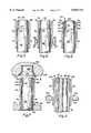
- FIG. 1is a perspective view of the endoscopic probe system of the present invention
- FIG. 2is an enlarged perspective view of the tip of the endoscopic probe of the present invention
- FIG. 3is an end elevational view of the probe tip depicted in FIG. 2;
- FIG. 4is a perspective view of a first preferred embodiment of the tip of the optical fiber component of the endoscope of the present invention
- FIG. 5is a side cross-sectional view of the tip of the optical fiber portion of the present invention, taken along lines 5--5 of FIG. 4;
- FIG. 6is a side cross-sectional view depicting a step in the manufacturing of the optical fiber tip of the present invention.
- FIG. 7is a side cross-sectional view depicting another step in the manufacturing of the optical fiber tip of the present invention.
- FIG. 8is a side cross-sectional view of the optical fiber tip of the present invention at the completion of manufacturing
- FIG. 9is a side cross-sectional view of the endoscope tip of the present invention, depicting a step in the manufacturing thereof;
- FIG. 10is a side cross-sectional view of the endoscope tip of the present invention, depicting a further step in the manufacturing thereof;
- FIG. 11is a side cross-sectional of the tip of the endoscopic probe of the present invention upon completion of manufacturing
- FIG. 12is a perspective view of an alternative embodiment of the tip of the optical fiber component of the endoscope of the present invention.
- FIG. 13is a side cross-sectional view of the tip depicted in FIG. 12, taken along lines 13--13 of FIG. 12.
- FIG. 1depicts the endoscopic probe system 10 of the present invention including a long, thin, flexible endoscopic probe 12 having a proximal end 14 and a distal end 16 which terminates in a probe tip 18.
- the probe 12is formed using a flexible extrusion tube 17, such as a PEBAX tube, having a plurality of tubular passages formed axially therewithin for the insertion of various components of the probe 12, from the proximal end 14 to the distal end 16; PEBAX is a trademark of Ato Shimie, Curbevole, France.
- the probe tip 18comprises the end tip of the PEBAX tube 17 with various components as are herein described.
- the probe system 10includes an illumination system 19 including a light source 20 that projects viewing light through an optical fiber 22 to a light emitting tip 24 engaged in the tip 18 of the endoscopic probe 12. Such illumination systems 19 are well known in the prior art which also may include two or more light emitting optical fibers with individual tips.
- the probe system 10also includes a viewing system 26 which receives imaging data through a coherent optical fiber 28 that passes through the probe 12 to a tip 30 disposed in the probe tip 18.
- the tip 30includes an optical lens 50 as is known in the art.
- the system 10may also include further components as are known in the art, such as an irrigation system 31 or a tissue sampling system 32 which operates through a hollow tubular passage 34 of the extrusion tube 17 and terminates at a passage tip 36.
- Such irrigation systems 31 and tissue sampling systems 32are well known in the prior art. Also known in the prior art, and not depicted herein for clarity sake, are probe movement systems, such as wires that pass through the probe 12 to control the movement of the distal end 16 of the probe 12.
- FIGS. 2 and 3depict the distal end 16 of the probe 12, wherein FIG. 2 is an enlarged perspective view thereof and FIG. 3 is an end elevational view thereof.
- the distal end 16includes a cylindrical outer sleeve member 40 that surrounds and mechanically compresses the tip end 18 to hold the light emitting probe tip 24, the video imaging tip 30 and the tissue probe passage tip 36 within the extrusion tube 17.
- the sleeve 40is radially inwardly mechanically deformed at its leading edge 44 to accomplish the mechanical holding of the tips 24, 30 and 36 together within the tip 18.
- a cylindrical sleeve 38is preferably inserted within the tip 36 of the passage 34 to avoid compression of the walls of the flexible tube into the passage tip 36.
- the manufacturing process for creating the deformation of the edge 44 of the sleeve 40 to accomplish the mechanical holding of the three tips 24, 30 and 36is discussed hereinbelow with the aid of FIGS. 8, 9 and 10.
- FIGS. 4 and 5depict a first preferred engagement method of the optical lens 50 to the coherent optical fiber 28, wherein FIG. 4 is a perspective view of the video imaging tip 30, and FIG. 5 is a side cross-sectional view taken along lines 5--5 of FIG. 4.
- the video imaging tip 30includes the optical lens 50 that is fixedly engaged to the end of the coherent optical fiber 28 utilizing a mechanical engagement that is created by using a deformable sleeve 52 preferably composed of a metal such as a copper based alloy or gold or other suitable material as would be known to those skilled in the art.
- optical lens 50is preferably formed as a solid cylindrical lens body having a convex exterior surface 58 and a flat interior surface 60.
- the interior face 60 of the lens 50is butted against the end 64 of the coherent optical fiber 28.
- Such lenses 50 and coherent optical fibers 28are well known in the endoscopic art, and are typically engaged together utilizing a transparent epoxy type adhesive.
- a significant feature of the present inventionis that the lens 50 is mechanically engaged to the coherent optical fiber end 64 utilizing the cylindrical sleeve 54.
- the inner diameter of the cylindrical sleeve 54closely matches the outer diameter of the optical fiber 28 and lens 50, such that a generally snug fit is obtained.
- the outer edge 68 of the sleeve 54is mechanically deformed inwardly to frictionally engage the outer surface of the cylindrical lens 50, and the shaft of the sleeve 54 is crimped 70 to engage the coherent optical fiber 28.
- FIGS. 6, 7 and 8depict the manufacturing steps that are utilized in the preferred manufacturing method for the engagement of the lens 50 to the optical fiber end 64.
- FIGS. 6, 7 and 8is a cross-sectional view that is similar to FIG. 5, however, the optical fiber 26 and sleeve 54 are preferably oriented vertically to utilize gravitational force to simplify the assembly method.
- the cylindrical sleeve 54is inserted over the end 64 of the coherent optical fiber 28.
- the sleeve 54projects upwardly from the end 64 a sufficient distance such that the lens 50 may be placed within the sleeve 54.
- the sleeve 54is then adjusted vertically, such that a small tip portion 72 of the lens 50 projects outwardly from the upper end 76 of the sleeve 54.
- a standard crimping device 80is utilized to provide a lateral force 82 against the sides of the sleeve 54 to depress the sleeve sides inwardly to form the crimp 70 (see FIG. 7), whereby the optical fiber 28 and the sleeve 54 become mechanically engaged together.
- the outer end 76 of the sleeve 54is next deformed (as sleeve end 68 is depicted in FIG. 5) to engage the lens 50 to the end 64 of the optical fiber 28.
- the sleeve 54is engaged to the optical fiber 28 by the crimp 70 and the lens 50 is loosely engaged in the outer end of the sleeve 54, such that a portion 72 of the lens 50 projects beyond the upper end 76 of the sleeve 54.
- an impact mounting assembly devicesuch as is described in U.S. Pat. No. 5,305,406 is next utilized to mechanically engage the lens 50 within the sleeve 54.
- the lens mounting methodinvolves the placement of the optical fiber 28 with its crimp-attached sleeve 54 within a holding notch 90 formed in a holding member 92 of an impact assembly device, such that the rearward end 96 of the sleeve 54 rests against an inner surface 100 of the holding member 92, while the optical fiber 28 passes through the slot 90. Thereafter, an impact punch head 106 of the impact mounting device is moved into position 110 against the projecting distal end 76 of the sleeve 54.
- the impact head 106is formed with a conical recess 114 defined by inwardly converging sidewalls 118.
- the sidewalls 118converge to a cylindrical cavity 122 defined by sidewalls 126, which are dimensioned such that the diameter of the cylindrical cavity 122 is larger than the diameter of the lens 50. It is therefore to be understood that when the impact punch head 106 is forcefully directed 110 against the sleeve 54, that the sidewalls 118 of the conical cavity 114 will make an impact contact with the end 76 of the sleeve 54, while the lens 50 will project untouched into the cylindrical cavity 122.
- the contact of the rearward end 96 of the sleeve 54 with the surface 100 of the holding member 92acts to prevent the sleeve 54 from moving rearwardly when it is impacted at the outer end 76 by the impact head 106.
- FIG. 8depicts the finished mechanical engagement of the lens 50 to the optical fiber 26.
- the outer end 76 (now shown in phantom) of the sleeve 54has been deformed to create the inwardly projecting end 68, wherein a deformed portion 136 of the tip of the sleeve 54 has been mechanically depressed inwardly into frictional engagement with the cylindrical side surface 140 of the lens 50.
- the lens 50is mechanically, frictionally engaged in a butted relationship with the end 64 of the optical fiber 28.
- a liquid sealant formulation 142can be inserted into the circumferential gap 144 between the lens 50 and the sleeve 54, as depicted in FIG. 7. Thereafter, the outer end 76 of the sleeve 54 is deformed, as discussed above with regard to FIG. 8, and the sealant 142 thus remains within the gap 144 to provide a sealed mechanical engagement of the lens 50 within the sleeve 54.
- FIGS. 9, 10 and 11The manufacturing method for the endoscope of the present invention is depicted in FIGS. 9, 10 and 11, which manufacturing steps are similar to the manufacturing steps for the viewing system optical fiber probe tip 30.
- a sleeve 40surrounds the distal end 16 of the endoscopic probe 12.
- the cylindrical sleeve 38is disposed in the end 36 of the tubular passage 34, as discussed above, and the coherent optical fiber 28 with its mechanically engaged lens 50 projects through a tubular passage 150 axially formed through the PEBAX tube 17.
- the illumination optical fiber disposed within its tubular passagewayis not depicted in the cross sectional view of FIG. 9.
- the cylindrical sleeve 40is placed around the tip 16 of the probe 12 such that end 17 of the PEBAX tube projects slightly outwardly from the outer end 154 of the sleeve 40.
- a standard crimping means 158is then utilized to apply a radially inward force 160 against the sides of the sleeve 40 to crimp 164 the sleeve 40 into a mechanical engagement with the tip 16 of the probe 12.
- an impact mounting deviceis next utilized to further mechanically engage the sleeve 40 to the probe tip 16.
- the probe 12 with the sleeve 40 engaged by the crimp 164is placed within a slot 168 formed in a holding member 172 of an impact mount device.
- a suitable impact mount deviceis described in U.S. Pat. No. 5,305,406, as has been mentioned and incorporated hereabove.
- An impact head 176 of the impact mounting deviceis next brought into contact with the upper end 154 of the sleeve 40.
- the impact headis formed with a conical cavity 180 defined by inwardly depending sidewalls 182 which terminate in a cylindrical cavity 184 defined by cylindrical sidewalls 186.
- the diameter of the cylindrical cavity 184is greater than the diameter of the tip 17 of the probe 12, whereas the conical sidewalls 182 will make impact contact with the upper end 154 of the sleeve 40. It is to be further understood that when the impact head 176 makes impact contact with the outer end 154 of the sleeve 40 that the outer end 154 will be deformed inwardly to make frictional contact with the outer surface 190 of the probe tip 16. The rearward end 194 of the sleeve 40 rests upon the surface 196 of the holding member 172, such that the sleeve is immovable during the impact head contact.
- FIG. 11depicts the probe tip 16 following the impact mounting of the sleeve 40.
- the sleeve end 154(now shown in phantom) has been inwardly deformed, such that an inner portion 198 of the sleeve 40 makes frictional contact with the outer surface 190 of the probe tip 16, and the outer end 44 of the sleeve 40 is deformed, as previously described.
- the small cylindrical sleeve 38is placed within the end 36 of the tube passage 34 prior to impact mounting.
- the sleeve 38serves to provide mechanical rigidity to the outer end 36 of the tubular passage 34, which functions to prevent the collapse of the outer end 36 of the tubular passage 34 during impact mounting.
- a liquid sealant formulation 200can be inserted into the circumferential gap 202 between the surface 190 and the sleeve 40, as depicted in FIG. 10. Thereafter, the outer end 154 of the sleeve 40 is deformed, as discussed above with regard to FIG. 11, and the sealant 200 thus remains within the gap 202 to provide a sealed mechanical engagement of the probe tip 16 within the sleeve 40.
- FIGS. 12 and 13An alternative viewing lens tip 220 of the present invention is depicted in FIGS. 12 and 13, wherein FIG. 12 is a perspective view and FIG. 13 is a side cross-sectional view taken along lines 13--13 of FIG. 12.
- a lens 50being generally identical to lens 50 depicted FIGS. 4 and 5, and having a convex outer surface 58 and a plane inner surface 60 is butted against the end 64 of a coherent optical fiber 28.
- the lens 50is held in position against the end 64 utilizing a deformable sleeve 54, as has been described hereabove with reference to FIGS. 4 and 5.
- a method for manufacturing the tip 220commences by deforming the forward edge 68 of the sleeve 54, preferably utilizing an impact mounting assembly device such as is described in U.S. Pat. No. 5,305,406. After the front end 68 of the sleeve 54 has been deformed, the lens 50 is placed within the sleeve 54, followed by the optical fiber 28.
- the sleeve 54is crimped 70 to hold the sleeve and the optical fiber 28 together.
- the lens 50is mechanically held within the sleeve 54 in a butted relationship with the end 64 of the optical fiber 28.
- the endoscopic probe 12 of the present inventionincludes the mechanical engagement of various components at the tip of the probe.
- the present inventionis therefore repeatedly heat sterilizable utilizing an autoclave or similar apparatus, whereas prior art devices that use adhesives for primary engagement purposes cannot be repeatedly heat sterilized because of the adverse effect of heat upon the adhesives.
- the present inventionincludes both the impact mounting of the lens 50 to the optical fiber 28 in creating the imaging system, and the impact mounting of the outer sleeve 40 to the tip 18 of the probe 12 to securely engage the various components within the tip 18.
Landscapes
- Health & Medical Sciences (AREA)
- Life Sciences & Earth Sciences (AREA)
- Surgery (AREA)
- Optics & Photonics (AREA)
- Physics & Mathematics (AREA)
- Nuclear Medicine, Radiotherapy & Molecular Imaging (AREA)
- Medical Informatics (AREA)
- Radiology & Medical Imaging (AREA)
- Biophysics (AREA)
- Engineering & Computer Science (AREA)
- Biomedical Technology (AREA)
- Heart & Thoracic Surgery (AREA)
- Pathology (AREA)
- Molecular Biology (AREA)
- Animal Behavior & Ethology (AREA)
- General Health & Medical Sciences (AREA)
- Public Health (AREA)
- Veterinary Medicine (AREA)
- Endoscopes (AREA)
Abstract
Description
Claims (10)
Priority Applications (1)
| Application Number | Priority Date | Filing Date | Title |
|---|---|---|---|
| US08/678,620US5810713A (en) | 1996-07-10 | 1996-07-10 | Autoclavable endoscope |
Applications Claiming Priority (1)
| Application Number | Priority Date | Filing Date | Title |
|---|---|---|---|
| US08/678,620US5810713A (en) | 1996-07-10 | 1996-07-10 | Autoclavable endoscope |
Publications (1)
| Publication Number | Publication Date |
|---|---|
| US5810713Atrue US5810713A (en) | 1998-09-22 |
Family
ID=24723562
Family Applications (1)
| Application Number | Title | Priority Date | Filing Date |
|---|---|---|---|
| US08/678,620Expired - Fee RelatedUS5810713A (en) | 1996-07-10 | 1996-07-10 | Autoclavable endoscope |
Country Status (1)
| Country | Link |
|---|---|
| US (1) | US5810713A (en) |
Cited By (16)
| Publication number | Priority date | Publication date | Assignee | Title |
|---|---|---|---|---|
| US6572536B1 (en) | 1999-11-05 | 2003-06-03 | Visionary Biomedical, Inc. | Autoclavable flexible fiberscope |
| US6773395B2 (en)* | 2000-09-08 | 2004-08-10 | Olympus Corporation | Endoscope |
| US20040242965A1 (en)* | 2003-03-25 | 2004-12-02 | Forkey Richard E. | Optical device with lens positioning and method of making the same |
| US20050048531A1 (en)* | 1998-09-17 | 2005-03-03 | Affymetrix, Inc. | Methods for genetic analysis |
| US20060025655A1 (en)* | 2004-07-27 | 2006-02-02 | Martin Uram | Autoclavable endoscope |
| US20060173242A1 (en)* | 2004-12-13 | 2006-08-03 | Acmi Corporation | Hermetic endoscope assemblage |
| US20080045787A1 (en)* | 2005-12-13 | 2008-02-21 | Gyrus Acmi, Inc. | Medical device made with a super alloy |
| US20080080051A1 (en)* | 2006-09-28 | 2008-04-03 | Pentax Corporation | Distal end optical unit for electronic endoscope |
| WO2009039456A1 (en)* | 2007-09-19 | 2009-03-26 | Biolase Technology, Inc. | Probes and biofluids for treating and removing deposits from tissue surfaces |
| US20100261961A1 (en)* | 2006-12-21 | 2010-10-14 | Intuitive Surgical Operations, Inc. | Hermetically sealed distal sensor endoscope |
| US20130156375A1 (en)* | 2010-05-19 | 2013-06-20 | Japan Aviation Electronics Industry, Limited | Optical collimator and optical connector using same |
| EP2680050A1 (en)* | 2012-06-29 | 2014-01-01 | Omron Corporation | Head for fiber optic optoelectronic switch |
| US20190151586A1 (en)* | 2017-11-23 | 2019-05-23 | Evan Denis Schmitz | Telescopic endotracheal intubation bougie |
| US11337598B2 (en) | 2010-05-13 | 2022-05-24 | Beaver-Visitec International, Inc. | Laser video endoscope |
| US11382496B2 (en) | 2006-12-21 | 2022-07-12 | Intuitive Surgical Operations, Inc. | Stereoscopic endoscope |
| US11490792B2 (en)* | 2019-06-03 | 2022-11-08 | Karl Storz Se & Co Kg | Video endoscope and method for configuring a video endoscope |
Citations (2)
| Publication number | Priority date | Publication date | Assignee | Title |
|---|---|---|---|---|
| US4790295A (en)* | 1986-12-16 | 1988-12-13 | Olympus Optical Co., Ltd. | Endoscope having transparent resin sealing layer |
| US5339800A (en)* | 1992-09-10 | 1994-08-23 | Devmed Group Inc. | Lens cleaning means for invasive viewing medical instruments with anti-contamination means |
- 1996
- 1996-07-10USUS08/678,620patent/US5810713A/ennot_activeExpired - Fee Related
Patent Citations (2)
| Publication number | Priority date | Publication date | Assignee | Title |
|---|---|---|---|---|
| US4790295A (en)* | 1986-12-16 | 1988-12-13 | Olympus Optical Co., Ltd. | Endoscope having transparent resin sealing layer |
| US5339800A (en)* | 1992-09-10 | 1994-08-23 | Devmed Group Inc. | Lens cleaning means for invasive viewing medical instruments with anti-contamination means |
Cited By (38)
| Publication number | Priority date | Publication date | Assignee | Title |
|---|---|---|---|---|
| US20050048531A1 (en)* | 1998-09-17 | 2005-03-03 | Affymetrix, Inc. | Methods for genetic analysis |
| US6572536B1 (en) | 1999-11-05 | 2003-06-03 | Visionary Biomedical, Inc. | Autoclavable flexible fiberscope |
| US6773395B2 (en)* | 2000-09-08 | 2004-08-10 | Olympus Corporation | Endoscope |
| US7385772B2 (en) | 2003-03-25 | 2008-06-10 | Precision Optics Corporation | Optical device with lens positioning and method of making the same |
| US20040242965A1 (en)* | 2003-03-25 | 2004-12-02 | Forkey Richard E. | Optical device with lens positioning and method of making the same |
| US20060025655A1 (en)* | 2004-07-27 | 2006-02-02 | Martin Uram | Autoclavable endoscope |
| US6997868B1 (en)* | 2004-07-27 | 2006-02-14 | Martin Uram | Autoclavable endoscope |
| US8568300B2 (en) | 2004-12-13 | 2013-10-29 | Gyrus Acmi, Inc. | Hermetic endoscope assemblage |
| US20060173242A1 (en)* | 2004-12-13 | 2006-08-03 | Acmi Corporation | Hermetic endoscope assemblage |
| US7410462B2 (en) | 2004-12-13 | 2008-08-12 | Gyrus Acmi, Inc. | Hermetic endoscope assemblage |
| US20080300463A1 (en)* | 2004-12-13 | 2008-12-04 | Gyrus Acmi, Inc. | Hermetic endoscope assemblage |
| DE112005002972B4 (en)* | 2004-12-13 | 2019-05-16 | Gyrus ACMI, Inc. (n.d.Ges.d. Staates Delaware) | Hermetic endoscope assembly |
| US20080045787A1 (en)* | 2005-12-13 | 2008-02-21 | Gyrus Acmi, Inc. | Medical device made with a super alloy |
| US20090118577A9 (en)* | 2005-12-13 | 2009-05-07 | Gyrus Acmi, Inc. | Medical device made with a super alloy |
| US20080080051A1 (en)* | 2006-09-28 | 2008-04-03 | Pentax Corporation | Distal end optical unit for electronic endoscope |
| US8360967B2 (en)* | 2006-09-28 | 2013-01-29 | Hoya Corporation | Distal end optical unit for electronic endoscope |
| US9271633B2 (en) | 2006-12-21 | 2016-03-01 | Intuitive Surgical Operations, Inc. | Stereo camera for hermetically sealed endoscope |
| US11382496B2 (en) | 2006-12-21 | 2022-07-12 | Intuitive Surgical Operations, Inc. | Stereoscopic endoscope |
| US12023006B2 (en) | 2006-12-21 | 2024-07-02 | Intuitive Surgical Operations, Inc. | Stereoscopic endoscope |
| US11716455B2 (en) | 2006-12-21 | 2023-08-01 | Intuitive Surgical Operations, Inc. | Hermetically sealed stereo endoscope of a minimally invasive surgical system |
| US8556807B2 (en) | 2006-12-21 | 2013-10-15 | Intuitive Surgical Operations, Inc. | Hermetically sealed distal sensor endoscope |
| US9005113B2 (en) | 2006-12-21 | 2015-04-14 | Intuitive Surgical Operations, Inc. | Hermetically sealed endoscope |
| US20100261961A1 (en)* | 2006-12-21 | 2010-10-14 | Intuitive Surgical Operations, Inc. | Hermetically sealed distal sensor endoscope |
| US20160220107A1 (en)* | 2006-12-21 | 2016-08-04 | Intuitive Surgical Operations, Inc. | Hermetically sealed endoscope with optical component attached to inner protective window |
| US9565997B2 (en)* | 2006-12-21 | 2017-02-14 | Intuitive Surgical Operations, Inc. | Hermetically sealed endoscope with optical component attached to inner protective window |
| US11039738B2 (en) | 2006-12-21 | 2021-06-22 | Intuitive Surgical Operations, Inc. | Methods for a hermetically sealed endoscope |
| US9962069B2 (en) | 2006-12-21 | 2018-05-08 | Intuitive Surgical Operations, Inc. | Endoscope with distal hermetically sealed sensor |
| US10682046B2 (en) | 2006-12-21 | 2020-06-16 | Intuitive Surgical Operations, Inc. | Surgical system with hermetically sealed endoscope |
| WO2009039456A1 (en)* | 2007-09-19 | 2009-03-26 | Biolase Technology, Inc. | Probes and biofluids for treating and removing deposits from tissue surfaces |
| US11337598B2 (en) | 2010-05-13 | 2022-05-24 | Beaver-Visitec International, Inc. | Laser video endoscope |
| EP2573601A4 (en)* | 2010-05-19 | 2017-12-27 | Mitsubishi Pencil Company, Limited | Optical collimator and optical connector using same |
| US8967880B2 (en)* | 2010-05-19 | 2015-03-03 | Mitsubishi Pencil Company, Limited | Optical collimator and optical connector using same |
| US20130156375A1 (en)* | 2010-05-19 | 2013-06-20 | Japan Aviation Electronics Industry, Limited | Optical collimator and optical connector using same |
| EP2680050A1 (en)* | 2012-06-29 | 2014-01-01 | Omron Corporation | Head for fiber optic optoelectronic switch |
| US20190151586A1 (en)* | 2017-11-23 | 2019-05-23 | Evan Denis Schmitz | Telescopic endotracheal intubation bougie |
| US11490792B2 (en)* | 2019-06-03 | 2022-11-08 | Karl Storz Se & Co Kg | Video endoscope and method for configuring a video endoscope |
| US20230020728A1 (en)* | 2019-06-03 | 2023-01-19 | Karl Storz Se & Co Kg | Video Mediastinoscope and a Method For Its Configuration |
| US12016527B2 (en)* | 2019-06-03 | 2024-06-25 | Karl Storz Se & Co. Kg | Video mediastinoscope and a method for its configuration |
Similar Documents
| Publication | Publication Date | Title |
|---|---|---|
| US5810713A (en) | Autoclavable endoscope | |
| US10588497B2 (en) | Compact endoscope tip and method for constructing same | |
| JP3393539B2 (en) | Endoscope device | |
| US20200178782A1 (en) | Medical device with oled illumination light source | |
| JP3302096B2 (en) | Endoscope | |
| US7033317B2 (en) | Disposable endoscope and method of making a disposable endoscope | |
| EP2103248A3 (en) | Miniature endoscope with imaging fiber system | |
| US20080144998A1 (en) | Attaching optical fibers to actuator tubes with beads acting as spacers and adhesives | |
| US8035902B2 (en) | Optical unit for probe and optical unit producing method | |
| AU1601992A (en) | Laser video endoscope | |
| GB2317778A (en) | Endoscope | |
| JPH0627391A (en) | Endoscope coupler with liquid phase interface | |
| US20220061646A1 (en) | Apparatus and method for in vivo cleaning of an optical lens of a surgical visualization device | |
| CN105828689A (en) | Imaging device and endoscope device | |
| JP3607843B2 (en) | Endoscope | |
| JP2949653B2 (en) | Hard image scope | |
| JP3328044B2 (en) | Endoscope cover member | |
| JPH03165731A (en) | Endoscope | |
| WO2002043604A3 (en) | Apparatus for the transillumination imaging of teeth | |
| JPH1119028A (en) | Endoscope | |
| JPH06343595A (en) | Cover type endoscope | |
| JPS58190912A (en) | Endoscope | |
| JPH0643333A (en) | Optical fiber connector | |
| JPH06339453A (en) | Cover-equipped endoscope device | |
| JP3026501B2 (en) | Endoscope connector device |
Legal Events
| Date | Code | Title | Description |
|---|---|---|---|
| AS | Assignment | Owner name:VALQUEST MEDICAL, INC., A FLORIDA CORPORATION, CAL Free format text:ASSIGNMENT OF ASSIGNORS INTEREST;ASSIGNORS:RONDEAU, MICHEL Y.;COLLETTE, DAVID J.;DECARIA, CHRISTINE;REEL/FRAME:008134/0242;SIGNING DATES FROM 19960802 TO 19960825 Owner name:FIBOTECH, INC., A NEW JERSEY CORPORATION, CALIFORN Free format text:ASSIGNMENT OF ASSIGNORS INTEREST;ASSIGNORS:RONDEAU, MICHEL Y.;COLLETTE, DAVID J.;DECARIA, CHRISTINE;REEL/FRAME:008134/0242;SIGNING DATES FROM 19960802 TO 19960825 | |
| AS | Assignment | Owner name:SILICON VALLEY BANK, CALIFORNIA Free format text:SECURITY AGREEMENT;ASSIGNOR:VALDOR FIBER OPTICS INC.;REEL/FRAME:009430/0599 Effective date:19980824 | |
| AS | Assignment | Owner name:ADVENT LIMITED PARTNERS, MASSACHUSETTS Free format text:SECURITY INTEREST;ASSIGNOR:VALDOR FIBER OPTICS, INC.;REEL/FRAME:010024/0489 Effective date:19990224 | |
| AS | Assignment | Owner name:VALDOR FIBER OPTICS INC., CALIFORNIA Free format text:RELEASE BY SECURED PARTY;ASSIGNOR:SILICON VALLEY BANK;REEL/FRAME:011529/0106 Effective date:20001026 | |
| FEPP | Fee payment procedure | Free format text:PAT HOLDER CLAIMS SMALL ENTITY STATUS, ENTITY STATUS SET TO SMALL (ORIGINAL EVENT CODE: LTOS); ENTITY STATUS OF PATENT OWNER: SMALL ENTITY | |
| REMI | Maintenance fee reminder mailed | ||
| FPAY | Fee payment | Year of fee payment:4 | |
| SULP | Surcharge for late payment | ||
| AS | Assignment | Owner name:VALDOR FIBER OPTICS INC., CALIFORNIA Free format text:RELEASE BY SECURED PARTY;ASSIGNOR:ADVENT LIMITED PARTNERS;REEL/FRAME:016593/0759 Effective date:20050928 | |
| REMI | Maintenance fee reminder mailed | ||
| LAPS | Lapse for failure to pay maintenance fees | ||
| STCH | Information on status: patent discontinuation | Free format text:PATENT EXPIRED DUE TO NONPAYMENT OF MAINTENANCE FEES UNDER 37 CFR 1.362 | |
| FP | Lapsed due to failure to pay maintenance fee | Effective date:20060922 |