US5810698A - Exercise method and apparatus - Google Patents
Exercise method and apparatusDownload PDFInfo
- Publication number
- US5810698A US5810698AUS08/635,075US63507596AUS5810698AUS 5810698 AUS5810698 AUS 5810698AUS 63507596 AUS63507596 AUS 63507596AUS 5810698 AUS5810698 AUS 5810698A
- Authority
- US
- United States
- Prior art keywords
- pulley
- body support
- carriage
- relative
- frame
- Prior art date
- Legal status (The legal status is an assumption and is not a legal conclusion. Google has not performed a legal analysis and makes no representation as to the accuracy of the status listed.)
- Expired - Fee Related
Links
Images


Classifications
- A—HUMAN NECESSITIES
- A63—SPORTS; GAMES; AMUSEMENTS
- A63B—APPARATUS FOR PHYSICAL TRAINING, GYMNASTICS, SWIMMING, CLIMBING, OR FENCING; BALL GAMES; TRAINING EQUIPMENT
- A63B21/00—Exercising apparatus for developing or strengthening the muscles or joints of the body by working against a counterforce, with or without measuring devices
- A63B21/15—Arrangements for force transmissions
- A63B21/151—Using flexible elements for reciprocating movements, e.g. ropes or chains
- A63B21/154—Using flexible elements for reciprocating movements, e.g. ropes or chains using special pulley-assemblies
- A63B21/155—Cam-shaped pulleys or other non-uniform pulleys, e.g. conical
- A—HUMAN NECESSITIES
- A63—SPORTS; GAMES; AMUSEMENTS
- A63B—APPARATUS FOR PHYSICAL TRAINING, GYMNASTICS, SWIMMING, CLIMBING, OR FENCING; BALL GAMES; TRAINING EQUIPMENT
- A63B21/00—Exercising apparatus for developing or strengthening the muscles or joints of the body by working against a counterforce, with or without measuring devices
- A63B21/06—User-manipulated weights
- A63B21/062—User-manipulated weights including guide for vertical or non-vertical weights or array of weights to move against gravity forces
- A63B21/0622—User-manipulated weights including guide for vertical or non-vertical weights or array of weights to move against gravity forces with adjustable inclination angle of the guiding means
- A—HUMAN NECESSITIES
- A63—SPORTS; GAMES; AMUSEMENTS
- A63B—APPARATUS FOR PHYSICAL TRAINING, GYMNASTICS, SWIMMING, CLIMBING, OR FENCING; BALL GAMES; TRAINING EQUIPMENT
- A63B21/00—Exercising apparatus for developing or strengthening the muscles or joints of the body by working against a counterforce, with or without measuring devices
- A63B21/06—User-manipulated weights
- A63B21/068—User-manipulated weights using user's body weight
- A—HUMAN NECESSITIES
- A63—SPORTS; GAMES; AMUSEMENTS
- A63B—APPARATUS FOR PHYSICAL TRAINING, GYMNASTICS, SWIMMING, CLIMBING, OR FENCING; BALL GAMES; TRAINING EQUIPMENT
- A63B21/00—Exercising apparatus for developing or strengthening the muscles or joints of the body by working against a counterforce, with or without measuring devices
- A63B21/40—Interfaces with the user related to strength training; Details thereof
- A63B21/4027—Specific exercise interfaces
- A63B21/4033—Handles, pedals, bars or platforms
- A63B21/4035—Handles, pedals, bars or platforms for operation by hand
- A—HUMAN NECESSITIES
- A63—SPORTS; GAMES; AMUSEMENTS
- A63B—APPARATUS FOR PHYSICAL TRAINING, GYMNASTICS, SWIMMING, CLIMBING, OR FENCING; BALL GAMES; TRAINING EQUIPMENT
- A63B21/00—Exercising apparatus for developing or strengthening the muscles or joints of the body by working against a counterforce, with or without measuring devices
- A63B21/40—Interfaces with the user related to strength training; Details thereof
- A63B21/4041—Interfaces with the user related to strength training; Details thereof characterised by the movements of the interface
- A63B21/4047—Pivoting movement
- A—HUMAN NECESSITIES
- A63—SPORTS; GAMES; AMUSEMENTS
- A63B—APPARATUS FOR PHYSICAL TRAINING, GYMNASTICS, SWIMMING, CLIMBING, OR FENCING; BALL GAMES; TRAINING EQUIPMENT
- A63B23/00—Exercising apparatus specially adapted for particular parts of the body
- A63B23/035—Exercising apparatus specially adapted for particular parts of the body for limbs, i.e. upper or lower limbs, e.g. simultaneously
- A63B23/04—Exercising apparatus specially adapted for particular parts of the body for limbs, i.e. upper or lower limbs, e.g. simultaneously for lower limbs
- A63B23/0405—Exercising apparatus specially adapted for particular parts of the body for limbs, i.e. upper or lower limbs, e.g. simultaneously for lower limbs involving a bending of the knee and hip joints simultaneously
- A63B2023/0411—Squatting exercises
- A—HUMAN NECESSITIES
- A63—SPORTS; GAMES; AMUSEMENTS
- A63B—APPARATUS FOR PHYSICAL TRAINING, GYMNASTICS, SWIMMING, CLIMBING, OR FENCING; BALL GAMES; TRAINING EQUIPMENT
- A63B21/00—Exercising apparatus for developing or strengthening the muscles or joints of the body by working against a counterforce, with or without measuring devices
- A63B21/40—Interfaces with the user related to strength training; Details thereof
- A63B21/4027—Specific exercise interfaces
- A63B21/4029—Benches specifically adapted for exercising
- A63B21/4031—Benches specifically adapted for exercising with parts of the bench moving against a resistance during exercise
- A—HUMAN NECESSITIES
- A63—SPORTS; GAMES; AMUSEMENTS
- A63B—APPARATUS FOR PHYSICAL TRAINING, GYMNASTICS, SWIMMING, CLIMBING, OR FENCING; BALL GAMES; TRAINING EQUIPMENT
- A63B21/00—Exercising apparatus for developing or strengthening the muscles or joints of the body by working against a counterforce, with or without measuring devices
- A63B21/40—Interfaces with the user related to strength training; Details thereof
- A63B21/4041—Interfaces with the user related to strength training; Details thereof characterised by the movements of the interface
- A63B21/4045—Reciprocating movement along, in or on a guide
- A—HUMAN NECESSITIES
- A63—SPORTS; GAMES; AMUSEMENTS
- A63B—APPARATUS FOR PHYSICAL TRAINING, GYMNASTICS, SWIMMING, CLIMBING, OR FENCING; BALL GAMES; TRAINING EQUIPMENT
- A63B2220/00—Measuring of physical parameters relating to sporting activity
- A63B2220/30—Speed
- A63B2220/34—Angular speed
- A—HUMAN NECESSITIES
- A63—SPORTS; GAMES; AMUSEMENTS
- A63B—APPARATUS FOR PHYSICAL TRAINING, GYMNASTICS, SWIMMING, CLIMBING, OR FENCING; BALL GAMES; TRAINING EQUIPMENT
- A63B23/00—Exercising apparatus specially adapted for particular parts of the body
- A63B23/035—Exercising apparatus specially adapted for particular parts of the body for limbs, i.e. upper or lower limbs, e.g. simultaneously
- A63B23/12—Exercising apparatus specially adapted for particular parts of the body for limbs, i.e. upper or lower limbs, e.g. simultaneously for upper limbs or related muscles, e.g. chest, upper back or shoulder muscles
- A63B23/1209—Involving a bending of elbow and shoulder joints simultaneously
- A—HUMAN NECESSITIES
- A63—SPORTS; GAMES; AMUSEMENTS
- A63B—APPARATUS FOR PHYSICAL TRAINING, GYMNASTICS, SWIMMING, CLIMBING, OR FENCING; BALL GAMES; TRAINING EQUIPMENT
- A63B23/00—Exercising apparatus specially adapted for particular parts of the body
- A63B23/035—Exercising apparatus specially adapted for particular parts of the body for limbs, i.e. upper or lower limbs, e.g. simultaneously
- A63B23/12—Exercising apparatus specially adapted for particular parts of the body for limbs, i.e. upper or lower limbs, e.g. simultaneously for upper limbs or related muscles, e.g. chest, upper back or shoulder muscles
- A63B23/1245—Primarily by articulating the shoulder joint
- A63B23/1263—Rotation about an axis passing through both shoulders, e.g. cross-country skiing-type arm movements
Definitions
- the present inventionrelates to exercise equipment and more particularly, to an exercise apparatus that provides resistance to various arm, leg, and/or abdominal exercises as a function of a person's body weight.
- Most exercise equipmentis designed with a relatively specific purpose in mind. For example, a substantial amount of exercise equipment is dedicated to strength training exercise. Some such equipment is designed specifically to work and strengthen a particular muscle or muscle group, and other such equipment is designed to work and strengthen a variety of muscles and/or muscles groups either through accessories or adjustments to the equipment, or at a plurality of stations associated with the equipment. Despite the existence of numerous strength training devices, a need remains for a relatively simple apparatus that works all of the major muscle groups at a single station and without requiring complicated accessories or adjustments.
- aerobic equipmentis typically designed to facilitate a substantially longer continuous workout by providing relatively less resistance to the exercise movements.
- a needremains for a relatively simple apparatus that facilitates or incorporates both types of exercise at a single station and without requiring complicated accessories or adjustments.
- Yet another type or category of exercise equipmentis dedicated to stretching exercise. Most such equipment is designed to stretch a person's legs and/or back muscles by guiding and/or supporting a person's body through a complete range of motion. As compared to aerobic exercise equipment, and even strength training apparatus, stretching devices are typically designed to facilitate slow and deliberate exercise movements. Despite the existence of numerous aerobic exercise devices, a need remains for a relatively simple apparatus that facilitates aerobic exercise and encourages exercise through a full range of motion at a single station and without requiring complicated accessories or adjustments.
- a preferred embodiment of the present inventionprovides an exercise apparatus having a body supporting carriage mounted on a frame and movable relative to the frame at a desired angle relative to a floor surface on which the frame rests.
- a foot platformis mounted to a lower end of the frame and is accessible to receive and support the feet of a person lying supine against the carriage.
- the foot platformprovides a brace against which the person may push with his or her legs to drive the carriage upward relative to the frame.
- the foot platformis movably mounted to the frame and moves between a storage position in which the foot platform lies substantially flat against the frame, and an operable position in which the foot platform extends perpendicular to the direction traveled by the carriage relative to the frame (regardless of the particular angle relative to the floor surface).
- Right and left arms or leversare mounted on opposite sides of the carriage and are rotatable relative thereto.
- Each of the leversis connected to an upper end of the frame by means of a flexible line.
- a first flexible lineextends from a first end connected to the frame to a second end connected to a pulley or reel associated with the right lever
- a second flexible lineextends from a first end connected to the frame to a second end connected to a pulley or reel associated with the left lever.
- An intermediate portion of each flexible linewraps around a circumferential groove on a respective pulley.
- Each of the leversis configured and arranged to receive and move in cooperation with an arm of a person lying supine against the carriage.
- the axis of rotation of the leversis intended to approximately align with the person's shoulders.
- Each of the leversincludes a first portion and a second portion extending perpendicular to one another and designed to align with the person's upper arm and lower arm (or forearm), respectively.
- the first portion and second portion of each levercooperate to define a plane that extends generally perpendicular to the body supporting carriage and generally parallel to the pulleys.
- Each of the leversfurther includes a third, L-shaped portion extending from a distal end of a respective second portion, perpendicular to both pulleys and toward one another, and then parallel to a respective first portion, to provide a handgrip.
- the leversprovide force receiving members against which a person may push with his or her arms to drive the carriage upward relative to the frame and/or to discourage downward movement of the carriage relative to the frame.
- application of torque against the pulleys in a first directionis subject to gravitational force acting on the mass of the carriage-and person supported thereby.
- Sufficient torque applied in this first directioncauses the pulleys to rotate in the first direction and the flexible lines to wind about the pulleys, thereby drawing the carriage upward relative to the frame.
- Release of this torqueallows the pulleys to rotate in a second, opposite direction and the flexible lines to unwind from the pulleys, thereby allowing the carriage (under the influence of gravity) to return downward relative to the frame.
- the carriagemay be maintained in equilibrium at any point relative to the frame by applying a torque against the pulleys that just offsets the gravitational force acting on the carriage and the person.
- the amount of force required to drive the carriage upwardis a function of the person's body weight, as well as the angle of inclination at which the carriage moves upward.
- the necessary forcemay be applied through the person's arms only, or the person' legs only, or both, with the percentage contribution of each being infinitely variable.
- the present inventionprovides a significant advantage by allowing a person's arms and legs to work against a common resistance force. For example, if either the arms or the legs fatigue relatively faster, the person's body is allowed to compensate naturally, and no adjustments to the equipment are required. Moreover, if a particular limb is relatively weaker or is injured during exercise, the other limbs are immediately available to compensate and redistribute the load;
- Another advantage of the present inventionis that both strength training and aerobic exercises may be performed at a single station and without complicated accessories or adjustments. For example, a simple adjustment of the angle of inclination traversed by the carriage effectively changes the resistance level, thereby allowing transformation of the device from a strength training apparatus to an aerobic exercise apparatus, and vice versa. Another way of making this transformation between strength training and aerobic exercise is simply to switch between exercises using only arms or legs to exercises using both. Abdominal and lower back muscles may also be exercised in relative isolation by performing leg lifts and/or crunches while the carriage is in a lowermost, rest position and/or while using the arms to offset the gravitational force and maintain the carriage in an upward position. Thus, the present invention effectively and directly exercises all of the major muscle groups of the human body.
- the present inventionalso facilitates stretching exercises to the extent that it allows a full range of motion for the arms and legs.
- the carriageencourages proper posture and effectively eliminates stress on the lower back.
- the various available exercisesare weight bearing yet impart little or no impact to the joints.
- the present inventionis cost effective to manufacture and simple to use.
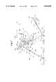
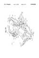
- FIG. 1is a perspective view of a first embodiment of an exercise apparatus constructed according to the principles of the present invention
- FIG. 2is a side elevation view of the exercise apparatus shown in FIG. 1;
- FIG. 3is a front view of the exercise apparatus shown in FIG. 1;
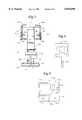
- FIG. 4is a plan view of a foot support forming a part of the exercise apparatus shown in FIG. 1;
- FIG. 5is a plan view of the electronic display monitor which is mounted on the exercise apparatus shown in FIG. 2;
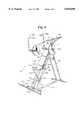
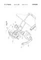
- FIG. 6is a perspective view of a second embodiment of an exercise apparatus constructed according to the principles of the present invention.
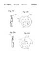
- FIG. 7is a front view of one of the pulleys which is connected to the exercise apparatus shown in FIG. 6;
- FIG. 8is a side view of the pulley shown in FIG. 7;
- FIG. 9is a front view of a mounting bar on which is mounted the pulley of FIG. 7;
- FIG. 10is a side view of the sliding bar shown in FIG. 9;
- FIG. 11is a front view of a cover bar which is connected to the pulley of FIG. 7;
- FIG. 12is a side view of the cover bar shown in FIG. 11;
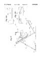
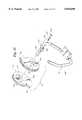
- FIG. 13is a side view of a third embodiment of an exercise apparatus constructed according to the principles of the present invention.
- FIG. 14ais a plan view of an upper portion of the exercise apparatus of FIG. 13, showing a flexible member in a first configuration, suitable for reciprocal movement of the handles;
- FIG. 14bis a plan view of an upper portion of the exercise apparatus of FIG. 13, showing a flexible member in a second configuration, suitable for independent movement of the handles;
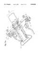
- FIG. 15ais a perspective view of a fourth embodiment of an exercise apparatus constructed according to the principles of the present invention, with the arms and carriage in a first position relative to the frame;
- FIG. 15bis a perspective view of the exercise apparatus of FIG. 15a, with the arms and carriage in a second position relative to the frame;
- FIG. 16is an exploded perspective view of the body support and the carriage on the exercise apparatus of FIGS. 15a and 15b;
- FIG. 17is an exploded perspective view of the body support of FIG. 16;
- FIG. 18is an exploded perspective view of the exercise apparatus of FIGS. 15a and 15b;
- FIG. 19is a top view of the exercise apparatus of FIGS. 15a and 15b;
- FIG. 20is a perspective view of a pulley and arm assembly on the exercise apparatus of FIGS. 15a and 15b;
- FIG. 21is an exploded view of the pulley and arm assembly of FIG. 20;
- FIG. 22ais a perspective view of the carriage on the exercise apparatus of FIGS. 15a and 15b;
- FIG. 22bis another perspective view of the carriage of FIG. 22a;
- FIG. 23ais an end view of a first cam plate on the exercise apparatus of FIGS. 15a and 15b;
- FIG. 23bis a side view of the cam plate of FIG. 23a;
- FIG. 24ais an end view of a second cam plate on the exercise apparatus of FIGS. 15a and 15b;
- FIG. 24bis an opposite side view of the cam plate of FIG. 24a.
- a first embodiment of an exercise apparatus constructed according to the principles of the present inventionis designated as 90 in FIGS. 1-3.
- the apparatus 90generally includes a frame 100, a body supporting means 200 movably connected to the frame 100, for supporting a person's body, a leg exercise means 300 connected to the frame 100, for facilitating leg exercises, and an arm exercise means 400 connected to the body supporting means 200, for facilitating arm exercises.
- the frame 100includes a floor engaging portion or base 110 which extends between a front end 101 and a rear end 102.
- the base 110includes a front transverse bar 111 and a rear transverse bar 121 which extend parallel to one another.
- a central longitudinal bar 105is interconnected between the front and rear bars 111 and 121 and cooperates therewith to define an I-shaped base 110.
- Right and left trunnions 122 and 123are secured to the rear bar 121 and extend generally perpendicular from the bar 121 and upward away from the floor surface 80.
- Right and left trunnions 112 and 113are secured to the front bar 111 and extend generally perpendicular from the bar 111 and upward away from the floor surface 80.
- the rearward trunnions 122 and 123provide a means for pivotally connecting right and left braces 131 and 141 to the rear bar 121.
- a right brace 131extends from a lower end 132 to an upper end 133, and the lower end 132 thereof is connected by a nut and bolt combination to the trunnion 122.
- a left brace 141extends from a lower end 142 to an upper end (not shown), and the lower end 142 thereof is connected by a nut and bolt combination to the trunnion 123.
- the right brace 131includes a first segment 134 and a second segment 135 which telescope relative to one another. At least one hole 136 is formed through the first segment 134, and several holes 137 are formed through the second segment 135 to receive a pin or other fastener 138 when the hole 136 is aligned with any of the holes 137. When inserted through an aligned pair of holes 136 and 137, the pin 128' prevents relative movement of the segments 134 and 135, thereby defining a fixed length for the right brace 131.
- a plurality of holesneed be provided in only the second segment 135 in order to facilitate this telescoping adjustment feature, but that the invention is not limited in this regard.
- the left brace 141similarly includes telescoping first and second segments 144 and 145 and holes 146 and 147 formed through the segments 144 and 145, respectively.
- a pin 148similarly inserts through any aligned pair of holes 146 and 147 to define a fixed length for the left brace 141.
- An elongate support 115extends between the trunnions 112 and 113 and is rotatably mounted relative thereto by means of pins extending from opposite ends of the support 115 and through holes in the trunnions 112 and 113.
- a right rail 151has a lower end 152 which is secured to the rotating support 115.
- the right rail 151is an elongate piece of steel tube having a square cross-section.
- the right rail 151extends from the lower end 152 to an upper end 153.
- a trunnion 154is connected to an intermediate portion of the right rail 151, relatively nearer the upper end 153.
- the trunnion 154extends rearward and downward from the rail 151, generally perpendicular thereto.
- the upper end 133 of the right brace 131is connected to the trunnion 154 by means of a nut and bolt combination, thereby pivotally connecting the right brace 131 to the right rail 151.
- the right rail 151, the right brace 131, and the base 110cooperate to form an acute triangle, and the angle A (shown in FIG. 2) between the right rail 151 and the base 110 is a function of the length of the right brace 131. In the embodiment 90, this angle A may be adjusted in five degree increments between a lower extreme of thirty degrees and an upper extreme of sixty degrees.
- a left rail 161similarly cooperates with the left brace 141 and the base 110 to form an acute triangle.
- the angle between the left rail 161 and the base 110(which coincides with the angle A) is similarly a function of the length of the left brace 141.
- a lower end 162 of the left rail 161is secured to the rotating support 115.
- the left rail 161is also an elongate piece of steel tube having a square cross-section.
- the left rail 161extends from the lower end 162 to an upper end 163, and a trunnion (not shown) extends rearward and downward from an intermediate portion of the right rail 161, relatively nearer the upper end 163.
- the upper end of the left brace 141is connected to the trunnion by means of a nut and bolt combination, thereby pivotally connecting the left brace 141 to the left rail 161.
- the braces 131 and 141extend substantially parallel to one another and cooperate to provide a brace or supporting means 140 for supporting the rails 151 and 161 in an inclined and adjustable orientation relative to the floor surface 80.
- the rails 151 and 161extend substantially parallel to one another and cooperate to provide a rail or guiding means 160 for guiding movement of the carriage 200 relative to the frame 100.
- the pivotal connections between the supporting means 140 and the guiding means 160 and the frame 100allow the apparatus 90 to fold down or collapse for storage and/or transportation.
- the body supporting means 200includes a carriage or platform 210 having a generally upwardly facing, body supporting surface 211 and an opposite, generally downwardly facing surface, which faces toward the rails 151 and 161.
- the body supporting surface 211is substantially flat and extends from an upper end 213 to a lower end 214.
- Fixed handles 251 and 252extend from opposite sides of the carriage 210, proximate the lower end 214.
- a lip or partial seat 215extends at an angle of approximately 120 degrees relative thereto.
- rollers 221are secured to the opposite or back surface of the carriage 210, proximate the upper end 213 thereof, and are rotatable relative thereto.
- These "upper” rollers 221are disposed between the carriage 210 and the rails 151 and 161 and roll along generally upwardly facing surfaces 159 and 169, respectively.
- Two more rollers 225are secured to the back surface of the carriage 210, proximate the lower end 214 thereof, and are rotatable relative thereto.
- These "lower” rollers 225are similarly disposed between the carriage 210 and the rails 151 and 161 and roll along the same generally upwardly facing surfaces 159 and 169, respectively.
- two “intermediate” rollers 229are rollably mounted relative to the back surface of the carriage 210 and rollable along the rails 151 and 161.
- Two additional rollers 231are secured to the back surface of the carriage 210, relative to the same brackets as those associated with the intermediate rollers 229, and are rotatable relative thereto. These rollers 231 are disposed on the opposite sides of the rails 151 and 161, respectively, and roll along generally downwardly facing surfaces thereon. These "underside” rollers 231 maintain the carriage 200 in close proximity to the rails 151 and 161 and cooperate with the rollers 221, 225, and 229 to provide a connecting means for movably connecting the carriage 200 to the frame 100.
- a pin 192may be inserted through holes in the brackets for at least one of the rollers 231 and in at least one of the rails 151 and 161 to lock the carriage 210 in place relative to the rails 151 and 161 if and when desired.
- carriage 200is movably connected to the frame 100 by means of rollers in the embodiment 90, those skilled in the art will recognize that the carriage may be movably connected to the frame in other ways without departing from the scope of the present invention.
- a four bar linkagecould be substituted with the carriage functioning as the so-called coupler.
- the leg exercising means 300includes a foot support or platform 310 having a generally upwardly facing, foot supporting surface 311 and an opposite, generally downwardly facing surface 312, which faces generally toward the floor 80.
- a cantilevered bar 321extends from a first end 322 connected to the "underside" 312 of the foot support 310, to a second end 323 connected to the frame 100.
- the second end 323is connected by means of a nut and bolt combination to a trunnion 116 mounted on the rotating support 115.
- the foot support 310is pivotally connected to the rotating support 115 and extends in cantilever fashion from this point of connection.
- the bar 321In an operative position, the bar 321 is rotated away from the rails 151 and 161 until the second end 323 of the bar 321 engages the rotating support 115 directly beneath the trunnion 116. At this extreme position, the bar 321 and the foot platform 310 extend substantially perpendicular to the rails 151 and 161, regardless of the orientation of the rails 151 and 161 relative to the frame 100 and/or the floor surface 80. For storage and/or transportation purposes, the bar 321 and the foot platform 310 are free to rotate toward the rails 151 and 161 to an orientation substantially parallel and adjacent thereto.
- the foot support 310is configured and arranged to support the feet of a person lying supine against the carriage 210. As shown in FIG. 4, guides or outlines 319 are provided on the upwardly facing surface 311 to indicate desirable foot positions. So long as the carriage 210 is free to roll along the rails 151 and 161, a person can position his or her feet approximately as indicated by the guides 319, and perform "squats” and/or “calf raises” to drive the carriage 210 up and down the rails 151 and 161 and thereby exercise the leg muscles. By altering the orientation and/or position of the feet (which may be suggested by additional guides on the upwardly facing surface 311) on the foot support 310, a person can focus the exercises on inner or outer leg muscles. Also, the foot support 310 cooperates with the carriage 210 to encourage proper posture and weight distribution during such exercises.
- the arm exercising means 400includes right and left arms or levers 420 and 440 rotatably connected to the carriage 200.
- a U-shaped bar 401is secured to the back side of the carriage 200 in such a manner that a first end segment 402 extends forward and to one side (the right) of the body supporting surface 211, and a second end segment 404 extends forward and to an opposite side (the left) of the surface 211.
- a first intermediate segment 403is secured to the U-shaped bar 401, proximate the first end segment 402 and extending generally parallel thereto.
- a reel or pulley 412is rotatably secured between the intermediate segment 403 and the end segment 402 by means of a nut and bolt combination.
- a second intermediate segment(not shown) is secured to the U-shaped bar 401, proximate the second end segment 404 and extending generally parallel thereto, and a reel or pulley 414 is rotatably secured between the intermediate segment and the end segment 403 by means of a nut and bolt combination.
- the first or right arm 420is secured to the right pulley 412 and rotates together therewith or not at all.
- the right arm 420includes a first, L-shaped member 421 having a radial segment 422 and a tangential segment 423.
- the radial segment 422is secured to the pulley 412 and extends radially away from the axis of rotation (designated as 411 in FIGS. 2 and 3) and beyond the circumference thereof.
- the tangential segment 423is integrally connected to a distal end of the radial segment 422 and extends generally perpendicular thereto, and thus, tangential to the pulley 412.
- the right arm 420further includes a second member 431 having a first segment 432 that telescopes into and out of the tangential segment 423 on the first member 420.
- a pin 429inserts through a hole in the tangential segment 423 and any of several holes 433 in the first segment 432 to adjustably secure the two telescoping segments 423 and 432 together.
- the second member 431further includes a second segment or axial segment 434 integrally connected to a distal end of the first segment 433 and extending parallel to the axis 411, and perpendicular to a plane defined by the first, L-shaped member 421.
- a third segment or handle 435is integrally connected to an opposite end of the second segment 434 and extends in the same general direction as the radial segment 422 on the first member 421.
- a padded support 439is mounted on the radial segment 422 and defines a plane generally perpendicular to the tangential segment 423.
- the padded support 439provides a brace against which a person may press with the rear of his or her right, upper arm.
- the tangential segment 423 and the first segment 432cooperate to parallel the person's right, lower arm or right forearm, and to define an effective length commensurate therewith.
- the third segment or handle 435provides a grip for the person's right hand.
- the second or left arm 440is secured to the left pulley 414 and rotates together therewith or not at all.
- the left arm 440includes a first, L-shaped member 441 having a radial segment 442 and a tangential segment 443.
- the radial segment 442is secured to the pulley 414 and extends radially away from the axis of rotation 411 and beyond the circumference thereof.
- the tangential segment 443is integrally connected to a distal end of the radial segment 442 and extends generally perpendicular thereto, and thus, tangential to the pulley 414.
- the left arm 440further includes a second member 451 having a first segment 452 that telescopes into and out of the tangential segment 443 on the first member 441.
- a pin 449inserts through a hole in the tangential segment 443 and any of several holes 453 in the first segment 452 to adjustably secure the two telescoping segments 443 and 452 together.
- the second member 451further includes a second segment or axial segment 454 integrally connected to a distal end of the first segment 452 and extending parallel to the axis 411, and perpendicular to a plane defined by the first, L-shaped member 441.
- a third segment or handle 455is integrally connected to an opposite end of the second segment 454 and extends in the same general direction as the radial segment 442 on the first member 441.
- a padded support 459is mounted on the radial segment 442 and defines a plane generally perpendicular to the tangential segment 443.
- the padded support 459provides a brace against which a person may press with the rear of his or her left, upper arm.
- the tangential segment 443 and the first segment 452cooperate to parallel the person's left, lower arm or forearm, and to define an effective length commensurate therewith.
- the third segment or handle 455provides a grip for the person's left hand.
- An upper transverse bar 171is connected to the upper ends 153 and 163 of the rails 151 and 161, respectively.
- the bar 171extends from a right distal end 176 to a left distal end 177 and perpendicular to the rails 151 and 161.
- a first flexible line 461has a first end 462 connected to the right distal end 176 by means of a loop in the line and a catch on the bar 171.
- the right pulley 412has a circumferential groove 413 which is suitable for accommodating at least one wind of the flexible line 461.
- the flexible line 461extends from the bar 171 and winds partially about the groove 413, terminating in a second looped end 463 which is connected to the pulley 412 by means of a pin 418 inserted through the looped end 463 and the pulley 412, just radially inward from the groove 413.
- a second flexible line 471has a first looped end 472 connected to the left distal end 177 of the transverse bar 171 by means of another catch on the bar 171.
- the left pulley 414similarly has a circumferential groove 415 which is suitable for accommodating at least one wind of the flexible line 471.
- the flexible line 471extends from the bar 171 and winds partially about the groove 415, terminating in a second looped end 473 which is connected to the pulley 414 by means of a pin 419 inserted through the looped end 473 and the pulley 414, just radially inward from the groove 415.
- the interconnection of the flexible lines 461 and 471 between the respective pulleys 412 and 414 and the frame 100may be said to link rotation of the arms 420 and 440 relative to the carriage 210 to linear movement of the carriage 210 relative to the frame 100.
- This same interconnectionalso may be said to convert torque applied against the arms 420 and 440 into force applied against gravity acting upon the mass of the carriage 210 and the user.
- movement of the arms 420 and 440 from the position shown in solid lines in FIG. 2 to the position shown in phantom lines in FIG. 2causes upward travel of the carriage 210 (from the position shown in solid lines to the position shown in phantom lines).
- a certain length of flexible cord 461 and 471unwinds from a respective pulley 412 and 414, and this "certain length" equals the distance between the uppermost position and the lowermost position.
- the uppermost positionis dictated by the length of a user's legs; the lowermost position is dictated by motion limiting stops 416 and 417 inserted through any of several holes through the pulleys 412 and 414, respectively.
- the stop 416interferes with the bars 401 and 403 between which the pulley 412 is rotatably mounted; and the stop 417 interferes with the bars 402 and 404 between which the pulley 414 is rotatably mounted.
- the selected location of the stops 416 and 417is a function of a user's range of motion and the size of the pulleys 412 and 414, as measured by the distance around the respective grooves 413 and 415.
- the stops 416 and 417are positioned so that the arms 420 and 440 can rotate up to two hundred and twenty degrees, from a generally upwardly extending position, in which the radial segments 422 and 442 are substantially parallel to the rails 151 and 161, to a generally downwardly extending position, in which the radial segments 422 and 442 are rotated behind the rails to define an angle of approximately forty degrees therebetween.
- the stops 416 and 417are intended to encourage proper exercise technique and minimize the possibility of injury.
- an electronics component 500may be mounted on the foot platform 310.
- the electronic display monitor 500includes a base plate 510 and a housing 520 supported thereon.
- a protruding portion of the base plate 510is secured to the underside of the foot platform 310 by means of bolts 509 secured within holes 519 formed through the base plate 510.
- a wire or cable 505extends from the housing 520, through a groove or channel 512 in the base plate, and into an opening in the end of the cantilevered bar 321.
- the cable 505is threaded through the bar 321 and into one of the rails 151 and 161 to a sensor (not shown).
- the senorcooperates with a magnet or other object (also not shown) on the carriage 210 to measure exercise data, such as speed and frequency of exercise movement.
- exercise datais transmitted through the cable 505 to the electronics within the housing 520.
- buttons 524 on the housing 520a person can set exercise parameters to be compared to the actual data and view the actual comparison on the display 522.
- the apparatus 90'includes a carriage 250 rollably mounted on a frame 100; a foot platform 310 rotatably mounted on a lower end of the frame 100; arms 420 and 440 rotatably mounted on the carriage 250; and cables 461 and 471 interconnected between respective arms 420 and 440 and the frame 100.
- the carriage 250includes a main body support 260 having a supporting surface 261 similar to that (211) on the first embodiment 90.
- a lip or partial seat 280is connected to the supporting surface 261 proximate its lower end.
- Brackets 281extend from opposite sides of the seat 280 and overlie supports 268 disposed behind the supporting surface 261. Holes through the brackets 281 align with holes through the supports 268 to receive rods and thereby selectively secure the seat 280 at any one of several positions along the supporting surface 261. In this manner, the apparatus 90' may be adjusted for persons having different leg lengths.
- the second embodiment 90'further includes a substantially Z-shaped bar 610 which is rigidly secured to the seat 280.
- the bar 610provides right and left handles 612 and 614 which may be grasped by a person lying supine against the carriage 210 to discourage slippage relative thereto while performing squats.
- the bar 610also provides a lateral foot support 616 on which a person may rest his or her feet while performing exercises that do not require use of the legs.
- An intermediate member 615extends between a right end of the right handle 612 and a left end of the foot support 616.
- the second embodiment 90'further includes a biasing means for selectively biasing the carriage 250 toward either the lowermost position of the uppermost position along the rails 151 and 161.
- a biasing meansfor selectively biasing the carriage 250 toward either the lowermost position of the uppermost position along the rails 151 and 161.
- an elastic cord 601is available to be selectively secured between the carriage 250 and either the rotating support 115 or the upper transverse bar 491.
- a clip or hookis secured to each end of the elastic cord 601, and one of these hooks interengages a catch or eyelet on the transverse bar 401 extending behind back side of the carriage 210.
- the other hookmay be connected to an eyelet 603 on the rotating support 115, proximate the lower ends of the rails 151 and 161, to cooperate with the gravitational force acting on the carriage 250 and thereby add resistance to upward movement of the carriage 250, as shown in FIG. 6.
- the other hookmay be connected to an eyelet 604 on the upper transverse bar 491, proximate the upper ends of the rails 151 and 161, to act against the gravitational force on the carriage 250 and thereby reduce resistance to upward movement of the carriage 250.
- the second embodiment 90'also provides a means for varying the relationship between rotation of the arms 420 and 440 and travel of the carriage 250.
- each of the arms 420 and 440is connected to a respective pulley 712 and 714 having an adjustable axis of rotation.
- the pulley 714which is representative of the pulley 712, is shown in FIGS. 7-8.
- the pulley 714is generally disc-shaped and includes an outwardly facing surface 701.
- a generally rectangular depression 704is formed in the surface 701 to slideably receive a mounting bar 740 which is shown in FIGS. 9-10.
- a slot 705is nested within the depression 704 and extends through the pulley 714.
- the slot 705is elongate and has rounded ends.
- the mounting bar 740includes a generally rectangular bar 741 sized and configured to slide within the depression 704 and lie beneath the surface 701.
- a pin 745connects the bar 741 to a shaft 746 which extends perpendicularly away from one side of the bar 741.
- the shaft 745extends through the slot 705 and mates with a collar on the arm 440.
- a plurality of holes 749are formed through the bar 741 and spaced along the longitudinal axis thereof.
- a second, generally rectangular depression 706is formed in the surface 701 of the pulley 714.
- the second depression 706extends perpendicular to the first depression 704, and the two depressions 704 and 706 are centered relative to one another and the pulley 714.
- the second depression 706is shallower than the first depression 704, and the bar 741 lies substantially coplanar with the bottom of the depression 706.
- the second depression 706receives a cover bar 760 which is shown in FIGS. 11-12.
- the cover bar 760includes a generally rectangular bar 761 sized and configured to nest within the second depression 706 and lie flush with the surface 701.
- the bar 761overlies the mounting bar 740 and is secured in place by screws extending through holes 767 in the bar 761 and holes 707 in the pulley 714.
- Another hole 769is formed through the bar 761 proximate the center thereof.
- the central hole 769is similar in size to the holes 749 in the mounting bar 740.
- a pin 799is inserted through the central hole 769 and any aligned hole 749 to stabilize the pulley 714 at a desired position relative to its axis of rotation (as defined by the shaft 746).
- a user of the apparatus 90'can readily adjust the apparatus so that the levers 420 and 440 approach their uppermost position when the user approaches a fully squatted position relative to the foot support 310, regardless of the user's height.
- this feature, as well as the other features of the second embodimentmay be combined, individually or as a whole, with the features present on the first embodiment.
- a third embodiment of an exercise apparatus constructed according to the principles of the present inventionis designated as 90" in FIG. 13.
- the apparatus 90"similarly includes a body supporting means 200 rollably mounted on a frame 100; a foot supporting means 300 rotatably mounted on a lower end of the frame 100; and arms 420 and 440 rotatably mounted on the body supporting means 200.
- a single flexible cord 481has a first end connected to the first pulley or reel 412 and a second end connected to the second pulley or reel 414.
- a first intermediate pulley 484is rotatably mounted on the right end of the upper transverse bar 491, and a similar, second intermediate pulley (not shown) is rotatably mounted on the left end of the bar 491.
- the cord 481extends tangentially from the first reel 412 to and about the first intermediate pulley 484 and then the second intermediate pulley, and then to the second reel 414.
- the arms 420 and 440can be worked in unison to drive the carriage 210 upward along the rail or guiding means 160, or in reciprocating fashion to maintain the carriage 210 at a given location along the rail or guiding means 160.
- an intermediate portion of the cord 481may be secured about bolts 495 and 496 (which protrude from the bar 491) to allow either arm 420 or 440 to be operated independently or in isolation.
- a first distal portion of the flexible line 481, extending from the first reel 412 to the first intermediate pulley 484,may be described as a first connecting means, for connecting the first arm 420 to the frame 100.
- a second, opposite distal portion of the flexible line 481, extending from second reel 414 to the second intermediate pulley (not shown),may be described as a second connecting means, for connecting the second arm 440 to the frame 100.
- An intermediate portion of the flexible line 481may be described as a third connecting means, for connecting the first connecting means to the second connecting means in a manner such that the first arm 420 and the second arm 440 are free to move in reciprocating fashion.
- the bolts 495 and 496may be described as a fourth connecting means, for connecting the first connecting means to the second connecting means in a manner such that said first arm and said second arm are free to move independent of one another.
- FIGS. 15a-24bA fourth and preferred embodiment of an exercise apparatus constructed according to the principles of the present invention is designated as 900 in FIGS. 15a-24b.
- This fourth embodiment 900is functionally similar in many respects to the other embodiments discussed above.
- the apparatus 900includes a frame 910 having a base portion 912 designed to rest upon a floor surface; a brace portion 914; and a rail portion 916.
- the frame 910 and its componentsfunction in the same general manner as their counterparts on the other embodiments discussed above.
- the frame 910includes rollers 919 rotatably mounted to a forwardmost part of the base portion 912 to facilitate relocation of the apparatus 900 when not in use.
- the apparatus 900further includes a carriage 920 that is rollably mounted on the rail portion 916 of the frame 910 in much the same manner as the body support on the other embodiments discussed above. Wear strips 906 are more above and beneath the rails 916 to facilitate smooth operation of rollers relative thereto.
- the fourth embodiment 900a body support 820 which is adjustably mounted relative to the carriage 920.
- a pair of fasteners 822project from underneath the body support 820 and terminate in oversized heads 824.
- a pair of openings 924 in the carriage 920receive the oversized heads 824, and a pair of relatively narrower slots 922 in the carriage 920 allow the fasteners 822 to slide along same.
- the heads 824are larger than the relatively narrower slots 922 and thus, slideably mount the body support 820 to the carriage 920.
- a pair of fasteners 826project from underneath the body support 820 and are of uniform diameter.
- Pairs of holes 926 in the carriage 920receive the fasteners 826 and together with gravity, lock the body support 820 in any of several positions along the carriage 920, thereby preventing sliding of the body support 820 relative to the carriage 920.
- This arrangementfacilitates adjustment of the body support 820 relative to a foot platform 930 (which is mounted to the frame 910 beneath the body support 820) to accommodate people having different physical needs.
- the foot platform 930is molded plastic and functions in the same manner as its counterparts on the other embodiments discussed above.
- a depression 933is formed in the foot platform 930 to receive an electronic display.
- a bracket 939is secured across the rail members 916 to provide a stop or support which limits the angle to which the foot platform 930 is pivoted away from the rails 916.
- the fourth embodiment 900includes a seat portion 828 and a handlebar 829 secured proximate its lower end.
- the handlebar 829is shaped generally like an unfastened coat hanger with separate ends secured to opposite sides of the body support 820.
- Arcuate notches or apertures 927are formed in each side of the carriage 920 to provide clearance for respective flexible lines, as explained below.
- the apparatus 900further provides right and left levers or handles 941 and 942 that rotate together with respective right and left pulleys 951 and 952 relative to the body support 820 and carriage 920.
- the levers 941 and 942 and the pulleys 951 and 952are rotatably mounted on common shafts.
- Each lever 941 and 942is secured to a respective pulley 951 and 952 by means of a pin 960 movably mounted on the lever 941 or 942 and insertable into any of a series of holes 956 in pulleys 951 or 952. All of the holes 956 are spaced at a common radial distance from the axis of rotation 949 common to the levers 941 and 942 and the pulleys 951 and 952.
- each pin 960includes a shaft 962 which projects into any of the holes 956 in a respective pulley 951 or 952.
- Each pin 960also includes a spring 964 which biases the shaft 962 toward the respective pulley 951 or 952.
- Each pin 960further includes a rod 966 which extends perpendicular to the shaft 962 and cooperates with a slot 949 formed in a collar or sleeve on a respective lever 941 or 942. In particular, this transverse rod 966 must be aligned with the slot 949 for the shaft 962 to move toward the respective pulley 951 or 952.
- the transverse rod 966keeps the shaft 962 at a distance from the respective pulley 951 or 952, in which case the respective pulley 951 or 952 is free to rotate relative to the respective lever 941 or 942. Since the levers 941 and 942 and the pins 960 are disposed between or inside of the pulleys 951 and 952, the pins are accessible to a person lying supine on the body support 820.
- Each of the pulleys 951 and 952includes a first cam plate 953, shown in FIGS. 23a-23b, and a second cam plate 954, shown in FIGS. 24a-24b.
- Each set of cam plates 953 and 954is connected by means of fasteners (not shown) extending through holes 955 in the cam plates 953 and 954.
- Each of the cam plates 953 and 954also the holes 956 formed therein to selectively receive one of the pins 960.
- Each of the cam plates 953 and 954also may be described as having a gradually increasing diameter (as a function of angular displacement) which cooperates with a flexible line to provide a cam effect.
- the cam plates 953 and 954are configured and arranged relative to one another so that a first cam plate 953 is “inside of” a second cam plate 954 on the first pulley 951, and a first cam plate 953 is “outside of” a second cam plate 954 on the second pulley 952.
- Each cam plate 953 and 954further includes holes 957 and 958 (see FIG. 23b) formed therein proximate the points of minimum and maximum radius to facilitate connection of cable ends thereto.
- a first flexible line 971 and 972is wound partially around and extends tangentially away from a respective pulley 951 and 952.
- Each flexible linehas a first end which is connected to a respective cam plate 953 or 954 by means of a fastener (not shown) extending through a respective hole 957.
- Each flexible line 971 or 972also has an intermediate portion which is routed from a respective pulley 951 or 952 to a respective first intermediate or routing pulley 981 or 982 that is rotatably mounted on a respective shaft 983 or 984.
- Each first intermediate pulley 981 or 982rotates about a respective axis of rotation (corresponding with a respective shaft 983 or 984) which extends generally perpendicular to the axis of rotation of a respective pulley 951 or 952.
- Each first intermediate pulley 981 or 982is positioned relative to a respective pulley 951 or 952 such that a line may be drawn tangent to both a circumferential surface on the respective pulley 951 or 952 and a circumferential surface on the respective intermediate pulley 981 or 982.
- Each first intermediate pulley 981 or 982guides a respective first flexible line 971 or 972 laterally through a respective notch 927 on the carriage 920 and behind the carriage 920 to a respective second intermediate pulley 985 or 986 that is rotatably mounted on a respective shaft 987 or 988.
- Each second intermediate pulley 985 or 986rotates about a respective axis of rotation (corresponding with a respective shaft 987 or 988) which extends generally perpendicular to both the axis of rotation of a respective pulley 951 or 952 and the axis of rotation of a respective first intermediate pulley 981 or 982.
- Each second intermediate pulley 985 or 986is positioned relative to a respective first intermediate pulley 981 or 982 such that a line may be drawn tangent to both the circumferential surface on the respective first intermediate pulley 981 or 982 and a circumferential surface on the respective second intermediate pulley 985 or 986.
- Each second intermediate pulley 985 or 986guides a respective first flexible line 971 or 972 toward the upper end of the frame 910, to which a second end of each flexible line 971 or 972 is secured.
- a second flexible line 976 and 977is wound partially around and extends tangentially away from a respective pulley 951 and 952.
- Each flexible line 976 and 977has a first end which is connected to a respective cam plate, 954 or 953 by means of a fastener (not shown) extending through a respective hole 958.
- Each flexible line 976 or 977also has an intermediate portion which is routed from a respective pulley 951 or 952 to a respective first intermediate or routing pulley 991 or 992 that is rotatably mounted on a respective shaft 993 or 994.
- Each first intermediate pulley 991 or 992rotates about a respective axis of rotation (corresponding with a respective shaft 993 or 994) which extends generally perpendicular to the axis of rotation of a respective pulley 951 or 952.
- Each first intermediate pulley 991 or 992is positioned relative to a respective pulley 951 or 952 such that a line may be drawn tangent to both a circumferential surface on the respective pulley 951 or 952 and a circumferential surface on the respective intermediate pulley 991 or 992.
- Each first intermediate pulley 991 or 992guides a respective second flexible line 976 or 977 laterally through a respective notch 927 on the carriage 920 and behind the carriage 920 to a respective second intermediate pulley 995 or 996 that is rotatably mounted on a respective shaft 997 or 998.
- Each second intermediate pulley 995 or 996rotates about a respective axis of rotation (corresponding with a respective shaft 997 or 998) which extends generally perpendicular to both the axis of rotation of a respective pulley 951 or 952 and the axis of rotation of a respective first intermediate pulley 991 or 992.
- Each second intermediate pulley 995 or 996is positioned relative to a respective first intermediate pulley 991 or 992 such that a line may be drawn tangent to both the circumferential surface on the respective first intermediate pulley 991 or 992 and a circumferential surface on the respective second intermediate pulley 995 or 996.
- Each second intermediate pulley 995 or 996guides a respective second flexible line 976 or 977 toward the upper end of the frame 910, to which a second end of each flexible line 976 or 977 is secured. This routing of the flexible lines adds to the number of parts needed to assemble the apparatus 900 but limits the exposed span of line and decreases the likelihood of a line coming out of its groove on the main pulley.
- the levers 941 and 942are mirror images of one another and have a somewhat different configuration than their counterparts discussed above with reference to the other embodiments.
- the levers 941may be described as more gently curved than the levers 420 and 440.
- the upper arm portion 944 of each lever 941 and 942is generally linear and supports a pad 946.
- the forearm and handle portion 948 of each lever 941 and 942extends from a distal end of the upper arm portion 944 and curves generally upward and toward the carriage 920.
- the gradual curvature of the lower portion 948provides a more continuous support designed to accommodate people of different sizes without the need for adjustments.
- a personshould lie supine against the carriage 210 and place his or her feet against the foot platform 310, generally as indicated by the guides 319 though allowing for personal comfort and/or special needs.
- the feetshould be spread apart slightly beyond shoulder width, and the toes should be directed straight ahead or slightly outward.
- the shouldersshould be aligned with the axis of rotation for the arms 420 and 440, and the back should rest firmly against the carriage 210.
- the headshould remain in contact with the carriage 210, as well.
- the present inventionfacilitates numerous different exercises, the combination of which includes elements of strength training, stretching, and aerobic exercise.
- These different exercisesinclude: (1) squats with one or two legs, and feet square; (2) squats with one or two legs, and feet pivoting back and forth; (3) squats with one or two legs and feet in a closed stance; (4) calf raises with one or two legs; (5) combined squats and pullovers, with one or two legs and one or two arms; (6) abdominal crunches, with carriage secured to rails; (7) abdominal crunches, with force exerted through arms to maintain carriage above lowermost position; and (8) leg lifts, with force exerted through arms to maintain carriage above lowermost position.
- Many of the foregoing exercisesmay be varied by (a) using the arms in reciprocating fashion; (b) adding the elastic cord biasing means; (c) varying the resistance, frequency, and/or range of motion for a particular movement to switch between strength training, stretching, and aerobic exercise.
Landscapes
- Health & Medical Sciences (AREA)
- Life Sciences & Earth Sciences (AREA)
- Biophysics (AREA)
- Orthopedic Medicine & Surgery (AREA)
- General Health & Medical Sciences (AREA)
- Physical Education & Sports Medicine (AREA)
- Rehabilitation Tools (AREA)
Abstract
Description
Claims (10)
Priority Applications (1)
| Application Number | Priority Date | Filing Date | Title |
|---|---|---|---|
| US08/635,075US5810698A (en) | 1996-04-19 | 1996-04-19 | Exercise method and apparatus |
Applications Claiming Priority (1)
| Application Number | Priority Date | Filing Date | Title |
|---|---|---|---|
| US08/635,075US5810698A (en) | 1996-04-19 | 1996-04-19 | Exercise method and apparatus |
Publications (1)
| Publication Number | Publication Date |
|---|---|
| US5810698Atrue US5810698A (en) | 1998-09-22 |
Family
ID=24546341
Family Applications (1)
| Application Number | Title | Priority Date | Filing Date |
|---|---|---|---|
| US08/635,075Expired - Fee RelatedUS5810698A (en) | 1996-04-19 | 1996-04-19 | Exercise method and apparatus |
Country Status (1)
| Country | Link |
|---|---|
| US (1) | US5810698A (en) |
Cited By (106)
| Publication number | Priority date | Publication date | Assignee | Title |
|---|---|---|---|---|
| US5906564A (en)* | 1998-01-31 | 1999-05-25 | Neill Jacobsen | Adjustable incline traveling platform exercise apparatus |
| US5928116A (en)* | 1998-01-20 | 1999-07-27 | Chiang; Yao-Chin | Body exerciser |
| US6004246A (en)* | 1998-03-27 | 1999-12-21 | Medx 96, Inc. | Lower back exercise machine including leg engaging assembly for isolating the lower torso |
| US6024677A (en)* | 1997-10-01 | 2000-02-15 | Siwertz; Torbjoern | Apparatus for physical exercise |
| WO2001014017A1 (en)* | 1999-08-23 | 2001-03-01 | Adnan Mizher | Device in particular for lumbar extension |
| US6244995B1 (en)* | 1999-06-02 | 2001-06-12 | Jan Prsala | Fitness exercise apparatus—the slider |
| US6428450B1 (en)* | 2001-05-21 | 2002-08-06 | Wei-Teh Ho | Sit-up exercising apparatus |
| US6482134B1 (en)* | 2000-07-12 | 2002-11-19 | Aaron P. Rasmussen | Aerobic sled exercise machine |
| US6632160B2 (en)* | 2000-11-30 | 2003-10-14 | Thruster Partners, Llc | Back roller exercise apparatus |
| WO2004078268A3 (en)* | 2003-03-03 | 2005-03-24 | Kyriacos Mark Zachary | Rotary torso exercise bench |
| US20050227826A1 (en)* | 2002-04-03 | 2005-10-13 | Takayuki Oga | Exercise assisting machine |
| US6971978B2 (en)* | 2002-12-12 | 2005-12-06 | Matthews Production Company, Inc. | Body weight gravity apparatus |
| US20060128535A1 (en)* | 2004-12-13 | 2006-06-15 | Nautilus, Inc. | Arm assembly for exercise devices |
| US7070545B2 (en) | 2002-07-01 | 2006-07-04 | Nautilus, Inc. | Leg press and abdominal crunch exercise machine |
| US7083554B1 (en) | 1997-02-27 | 2006-08-01 | Nautilus, Inc. | Exercise machine with infinite position range limiter and automatic belt tensioning system |
| US20060189462A1 (en)* | 2005-01-14 | 2006-08-24 | Nautilus, Inc. | Exercise device |
| US7108641B2 (en) | 2000-05-03 | 2006-09-19 | Nautilus, Inc. | Exercise equipment with multi-positioning handles |
| US7115080B2 (en) | 2002-08-01 | 2006-10-03 | Nautilus, Inc. | Collapsible seat for combination hack squat and leg press machine |
| USD533910S1 (en)* | 2005-03-15 | 2006-12-19 | Nautilus, Inc. | Exercise device |
| US20060293156A1 (en)* | 2002-10-29 | 2006-12-28 | Darin Trees | Therapeutic exercise device |
| US7220221B2 (en) | 2000-05-03 | 2007-05-22 | Nautilus, Inc. | Exercise device with body extension mechanism |
| US20070225136A1 (en)* | 2006-02-10 | 2007-09-27 | Maurizio Roman | Gymnastic machine |
| US20070232462A1 (en)* | 2003-11-03 | 2007-10-04 | Webber Randall T | Rigid arm pull down exercise machine |
| US20080132389A1 (en)* | 2003-11-03 | 2008-06-05 | Hoist Fitness Systems, Inc. | Shoulder press exercise machine |
| US20080153677A1 (en)* | 2003-08-04 | 2008-06-26 | Hoist Fitness Systems, Inc. | Leg press exercise machine with self-aligning pivoting seat |
| US20080176722A1 (en)* | 2007-01-22 | 2008-07-24 | Clay Steffee | Bidirectional resistance apparatus for exercise equipment |
| US20080214365A1 (en)* | 2003-08-04 | 2008-09-04 | Hoist Fitness Systems, Inc. | Rowing exercise machine with self-aligning pivoting user support |
| US20080248929A1 (en)* | 2003-08-04 | 2008-10-09 | Hoist Fitness Systems, Inc. | Multi-station exercise machine |
| US7549949B2 (en) | 2003-08-04 | 2009-06-23 | Hoist Fitness Systems, Inc. | Chest press exercise machine with self-aligning pivoting user support |
| US20090163331A1 (en)* | 2007-12-19 | 2009-06-25 | Mark Lacher | Exercise apparatus |
| US7563209B2 (en) | 2006-09-05 | 2009-07-21 | Hoist Fitness Systems, Inc. | Leg exercise machine with self-aligning pivoting seat |
| US7654940B2 (en)* | 2006-09-06 | 2010-02-02 | Hoist Fitness Systems, Inc. | Arm exercise machine with self-aligning pivoting user support |
| US7670269B2 (en) | 2006-09-05 | 2010-03-02 | Hoist Fitness Systems, Inc. | Chest press exercise machine with self-aligning pivoting user support |
| US20100105530A1 (en)* | 2008-10-27 | 2010-04-29 | Senoh Kabushiki Kaisha | Training Apparatus |
| US20100204023A1 (en)* | 2009-02-12 | 2010-08-12 | Brookstone Purchasing, Inc. | Adjustable resistance exercise device |
| US20100204024A1 (en)* | 2009-02-12 | 2010-08-12 | Brookstone Purchasing, Inc. | Adjustable resistance exercise device |
| US7794371B2 (en) | 2003-08-04 | 2010-09-14 | Hoist Fitness Systems, Inc. | Lat exercise machine with self-aligning pivoting user support |
| US7922635B2 (en) | 2000-03-10 | 2011-04-12 | Nautilus, Inc. | Adjustable-load unitary multi-position bench exercise unit |
| US7938760B1 (en) | 2008-10-17 | 2011-05-10 | Hoist Fitness Systems, Inc. | Exercise machine with lifting arm |
| US20110111925A1 (en)* | 2009-03-19 | 2011-05-12 | Tyler James Hobson | Neck exercise machine |
| US20110143898A1 (en)* | 2009-12-14 | 2011-06-16 | Hill-Rom Services, Inc. | Patient support apparatuses with exercise functionalities |
| US7981010B1 (en) | 2003-08-04 | 2011-07-19 | Hoist Fitness Systems, Inc. | Exercise machine with multi-function user engagement device |
| US7993251B1 (en) | 2003-08-04 | 2011-08-09 | Hoist Fitness Systems, Inc. | Pectoral fly exercise machine |
| US8177693B2 (en) | 2010-02-25 | 2012-05-15 | Hoist Fitness Systems, Inc. | Calf exercise machine with rocking user support |
| US8249714B1 (en) | 2005-07-08 | 2012-08-21 | Customkynetics, Inc. | Lower extremity exercise device with stimulation and related methods |
| US8562496B2 (en) | 2010-03-05 | 2013-10-22 | Hoist Fitness Systems, Inc. | Thigh exercise machine with rocking user support |
| US8734304B2 (en) | 2010-03-04 | 2014-05-27 | Hoist Fitness Systems, Inc. | Low back exercise machine with rocking user support |
| US9038218B1 (en) | 2014-01-15 | 2015-05-26 | Hill-Rom Services, Inc. | Person support apparatuses with selectively coupled foot sections |
| US9132051B2 (en) | 2014-01-15 | 2015-09-15 | Hill-Rom Services, Inc. | Person support apparatuses with exercise functionalities |
| US10188890B2 (en) | 2013-12-26 | 2019-01-29 | Icon Health & Fitness, Inc. | Magnetic resistance mechanism in a cable machine |
| US10212994B2 (en) | 2015-11-02 | 2019-02-26 | Icon Health & Fitness, Inc. | Smart watch band |
| US10252109B2 (en) | 2016-05-13 | 2019-04-09 | Icon Health & Fitness, Inc. | Weight platform treadmill |
| US10258828B2 (en) | 2015-01-16 | 2019-04-16 | Icon Health & Fitness, Inc. | Controls for an exercise device |
| US10272317B2 (en) | 2016-03-18 | 2019-04-30 | Icon Health & Fitness, Inc. | Lighted pace feature in a treadmill |
| US10279212B2 (en) | 2013-03-14 | 2019-05-07 | Icon Health & Fitness, Inc. | Strength training apparatus with flywheel and related methods |
| US10293211B2 (en) | 2016-03-18 | 2019-05-21 | Icon Health & Fitness, Inc. | Coordinated weight selection |
| US10343017B2 (en) | 2016-11-01 | 2019-07-09 | Icon Health & Fitness, Inc. | Distance sensor for console positioning |
| US10376736B2 (en) | 2016-10-12 | 2019-08-13 | Icon Health & Fitness, Inc. | Cooling an exercise device during a dive motor runway condition |
| US10426989B2 (en) | 2014-06-09 | 2019-10-01 | Icon Health & Fitness, Inc. | Cable system incorporated into a treadmill |
| US10433612B2 (en) | 2014-03-10 | 2019-10-08 | Icon Health & Fitness, Inc. | Pressure sensor to quantify work |
| US10441844B2 (en) | 2016-07-01 | 2019-10-15 | Icon Health & Fitness, Inc. | Cooling systems and methods for exercise equipment |
| US10441840B2 (en) | 2016-03-18 | 2019-10-15 | Icon Health & Fitness, Inc. | Collapsible strength exercise machine |
| US10449416B2 (en) | 2015-08-26 | 2019-10-22 | Icon Health & Fitness, Inc. | Strength exercise mechanisms |
| US10471299B2 (en) | 2016-07-01 | 2019-11-12 | Icon Health & Fitness, Inc. | Systems and methods for cooling internal exercise equipment components |
| US10493349B2 (en) | 2016-03-18 | 2019-12-03 | Icon Health & Fitness, Inc. | Display on exercise device |
| US10500473B2 (en) | 2016-10-10 | 2019-12-10 | Icon Health & Fitness, Inc. | Console positioning |
| US10543395B2 (en) | 2016-12-05 | 2020-01-28 | Icon Health & Fitness, Inc. | Offsetting treadmill deck weight during operation |
| US10561894B2 (en) | 2016-03-18 | 2020-02-18 | Icon Health & Fitness, Inc. | Treadmill with removable supports |
| US10625137B2 (en) | 2016-03-18 | 2020-04-21 | Icon Health & Fitness, Inc. | Coordinated displays in an exercise device |
| US10661114B2 (en) | 2016-11-01 | 2020-05-26 | Icon Health & Fitness, Inc. | Body weight lift mechanism on treadmill |
| US10729965B2 (en) | 2017-12-22 | 2020-08-04 | Icon Health & Fitness, Inc. | Audible belt guide in a treadmill |
| US10786706B2 (en) | 2018-07-13 | 2020-09-29 | Icon Health & Fitness, Inc. | Cycling shoe power sensors |
| US10874567B2 (en) | 2014-03-11 | 2020-12-29 | Hill-Rom Services, Inc. | Patient bed having footboard pedal apparatus for physical therapy |
| US10918905B2 (en) | 2016-10-12 | 2021-02-16 | Icon Health & Fitness, Inc. | Systems and methods for reducing runaway resistance on an exercise device |
| US10940360B2 (en) | 2015-08-26 | 2021-03-09 | Icon Health & Fitness, Inc. | Strength exercise mechanisms |
| US10953305B2 (en) | 2015-08-26 | 2021-03-23 | Icon Health & Fitness, Inc. | Strength exercise mechanisms |
| US10974096B2 (en)* | 2018-10-24 | 2021-04-13 | Louie Simmons | Hamstring exercise device and method of using same |
| US11000730B2 (en) | 2018-03-16 | 2021-05-11 | Icon Health & Fitness, Inc. | Elliptical exercise machine |
| US11033777B1 (en) | 2019-02-12 | 2021-06-15 | Icon Health & Fitness, Inc. | Stationary exercise machine |
| US11058913B2 (en) | 2017-12-22 | 2021-07-13 | Icon Health & Fitness, Inc. | Inclinable exercise machine |
| US11058914B2 (en) | 2016-07-01 | 2021-07-13 | Icon Health & Fitness, Inc. | Cooling methods for exercise equipment |
| US11187285B2 (en) | 2017-12-09 | 2021-11-30 | Icon Health & Fitness, Inc. | Systems and methods for selectively rotationally fixing a pedaled drivetrain |
| US11244751B2 (en) | 2012-10-19 | 2022-02-08 | Finish Time Holdings, Llc | Method and device for providing a person with training data of an athlete as the athlete is performing a swimming workout |
| US11298577B2 (en) | 2019-02-11 | 2022-04-12 | Ifit Inc. | Cable and power rack exercise machine |
| US11326673B2 (en) | 2018-06-11 | 2022-05-10 | Ifit Inc. | Increased durability linear actuator |
| US11451108B2 (en) | 2017-08-16 | 2022-09-20 | Ifit Inc. | Systems and methods for axial impact resistance in electric motors |
| US11534651B2 (en) | 2019-08-15 | 2022-12-27 | Ifit Inc. | Adjustable dumbbell system |
| US11534654B2 (en) | 2019-01-25 | 2022-12-27 | Ifit Inc. | Systems and methods for an interactive pedaled exercise device |
| US11673036B2 (en) | 2019-11-12 | 2023-06-13 | Ifit Inc. | Exercise storage system |
| US11794070B2 (en) | 2019-05-23 | 2023-10-24 | Ifit Inc. | Systems and methods for cooling an exercise device |
| US11850497B2 (en) | 2019-10-11 | 2023-12-26 | Ifit Inc. | Modular exercise device |
| US11878199B2 (en) | 2021-02-16 | 2024-01-23 | Ifit Inc. | Safety mechanism for an adjustable dumbbell |
| US11931621B2 (en) | 2020-03-18 | 2024-03-19 | Ifit Inc. | Systems and methods for treadmill drift avoidance |
| US11951377B2 (en) | 2020-03-24 | 2024-04-09 | Ifit Inc. | Leaderboard with irregularity flags in an exercise machine system |
| US11963918B2 (en) | 2020-04-20 | 2024-04-23 | Hill-Rom Services, Inc. | Patient bed having active motion exercise |
| US12029961B2 (en) | 2020-03-24 | 2024-07-09 | Ifit Inc. | Flagging irregularities in user performance in an exercise machine system |
| US12029935B2 (en) | 2021-08-19 | 2024-07-09 | Ifit Inc. | Adjustment mechanism for an adjustable kettlebell |
| US20240226653A1 (en)* | 2024-03-19 | 2024-07-11 | Christopher Contessa | Foldable hack squat and leg press machine and method of operating the same |
| US12176009B2 (en) | 2021-12-30 | 2024-12-24 | Ifit Inc. | Systems and methods for synchronizing workout equipment with video files |
| US12219201B2 (en) | 2021-08-05 | 2025-02-04 | Ifit Inc. | Synchronizing video workout programs across multiple devices |
| US12263371B2 (en) | 2021-04-27 | 2025-04-01 | Ifit Inc. | Devices, systems, and methods for rotating a tread belt in two directions |
| US12280294B2 (en) | 2021-10-15 | 2025-04-22 | Ifit Inc. | Magnetic clutch for a pedaled drivetrain |
| US12350547B2 (en) | 2022-02-28 | 2025-07-08 | Ifit Inc. | Devices, systems, and methods for moving a movable step through a transition zone |
| US12350573B2 (en) | 2021-04-27 | 2025-07-08 | Ifit Inc. | Systems and methods for cross-training on exercise devices |
| US12409375B2 (en) | 2022-03-18 | 2025-09-09 | Ifit Inc. | Systems and methods for haptic simulation in incline exercise devices |
| US12433815B2 (en) | 2020-10-02 | 2025-10-07 | Ifit Inc. | Massage roller with pressure sensors |
Citations (6)
| Publication number | Priority date | Publication date | Assignee | Title |
|---|---|---|---|---|
| US3998454A (en)* | 1973-05-15 | 1976-12-21 | Jones Arthur A | Force receiving exercising member |
| US4456245A (en)* | 1981-12-11 | 1984-06-26 | Nautilus Sports/Medical Industries, Inc. | Rotary torso exercise apparatus |
| US4911438A (en)* | 1986-08-29 | 1990-03-27 | Verimark (Proprietary) Limited | Exercising machine |
| US5056777A (en)* | 1990-02-15 | 1991-10-15 | Potential Training Products Co. Inc. | Force transmission mechanism for exercise machines |
| US5102121A (en)* | 1989-02-10 | 1992-04-07 | Lumex, Inc. | Device for limiting the range of motion on weight-lifting machines |
| US5169363A (en)* | 1991-10-15 | 1992-12-08 | Campanaro Thomas J | Lower extremity rehabilitation system |
- 1996
- 1996-04-19USUS08/635,075patent/US5810698A/ennot_activeExpired - Fee Related
Patent Citations (6)
| Publication number | Priority date | Publication date | Assignee | Title |
|---|---|---|---|---|
| US3998454A (en)* | 1973-05-15 | 1976-12-21 | Jones Arthur A | Force receiving exercising member |
| US4456245A (en)* | 1981-12-11 | 1984-06-26 | Nautilus Sports/Medical Industries, Inc. | Rotary torso exercise apparatus |
| US4911438A (en)* | 1986-08-29 | 1990-03-27 | Verimark (Proprietary) Limited | Exercising machine |
| US5102121A (en)* | 1989-02-10 | 1992-04-07 | Lumex, Inc. | Device for limiting the range of motion on weight-lifting machines |
| US5056777A (en)* | 1990-02-15 | 1991-10-15 | Potential Training Products Co. Inc. | Force transmission mechanism for exercise machines |
| US5169363A (en)* | 1991-10-15 | 1992-12-08 | Campanaro Thomas J | Lower extremity rehabilitation system |
Cited By (180)
| Publication number | Priority date | Publication date | Assignee | Title |
|---|---|---|---|---|
| US7083554B1 (en) | 1997-02-27 | 2006-08-01 | Nautilus, Inc. | Exercise machine with infinite position range limiter and automatic belt tensioning system |
| US6024677A (en)* | 1997-10-01 | 2000-02-15 | Siwertz; Torbjoern | Apparatus for physical exercise |
| US5928116A (en)* | 1998-01-20 | 1999-07-27 | Chiang; Yao-Chin | Body exerciser |
| US5906564A (en)* | 1998-01-31 | 1999-05-25 | Neill Jacobsen | Adjustable incline traveling platform exercise apparatus |
| US6004246A (en)* | 1998-03-27 | 1999-12-21 | Medx 96, Inc. | Lower back exercise machine including leg engaging assembly for isolating the lower torso |
| US6244995B1 (en)* | 1999-06-02 | 2001-06-12 | Jan Prsala | Fitness exercise apparatus—the slider |
| WO2001014017A1 (en)* | 1999-08-23 | 2001-03-01 | Adnan Mizher | Device in particular for lumbar extension |
| US7922635B2 (en) | 2000-03-10 | 2011-04-12 | Nautilus, Inc. | Adjustable-load unitary multi-position bench exercise unit |
| US7608028B2 (en) | 2000-05-03 | 2009-10-27 | Nautilus, Inc. | Exercise equipment with multi-positioning handles |
| US7220221B2 (en) | 2000-05-03 | 2007-05-22 | Nautilus, Inc. | Exercise device with body extension mechanism |
| US7108641B2 (en) | 2000-05-03 | 2006-09-19 | Nautilus, Inc. | Exercise equipment with multi-positioning handles |
| US6482134B1 (en)* | 2000-07-12 | 2002-11-19 | Aaron P. Rasmussen | Aerobic sled exercise machine |
| US6632160B2 (en)* | 2000-11-30 | 2003-10-14 | Thruster Partners, Llc | Back roller exercise apparatus |
| US6428450B1 (en)* | 2001-05-21 | 2002-08-06 | Wei-Teh Ho | Sit-up exercising apparatus |
| US20050227826A1 (en)* | 2002-04-03 | 2005-10-13 | Takayuki Oga | Exercise assisting machine |
| US7247128B2 (en)* | 2002-04-03 | 2007-07-24 | Oga Co., Ltd. | Exercise assisting machine |
| US7070545B2 (en) | 2002-07-01 | 2006-07-04 | Nautilus, Inc. | Leg press and abdominal crunch exercise machine |
| US7608022B2 (en) | 2002-07-01 | 2009-10-27 | Nautilus, Inc. | Leg press and abdominal crunch exercise machine |
| US7115080B2 (en) | 2002-08-01 | 2006-10-03 | Nautilus, Inc. | Collapsible seat for combination hack squat and leg press machine |
| US20060293156A1 (en)* | 2002-10-29 | 2006-12-28 | Darin Trees | Therapeutic exercise device |
| AU2003285047B2 (en)* | 2002-10-29 | 2008-06-05 | Djo, Llc | Therapeutic exercise device |
| US7597656B2 (en)* | 2002-10-29 | 2009-10-06 | Encore Medical Asset Corporation | Therapeutic exercise device |
| US6971978B2 (en)* | 2002-12-12 | 2005-12-06 | Matthews Production Company, Inc. | Body weight gravity apparatus |
| WO2004078268A3 (en)* | 2003-03-03 | 2005-03-24 | Kyriacos Mark Zachary | Rotary torso exercise bench |
| US7549949B2 (en) | 2003-08-04 | 2009-06-23 | Hoist Fitness Systems, Inc. | Chest press exercise machine with self-aligning pivoting user support |
| US7981010B1 (en) | 2003-08-04 | 2011-07-19 | Hoist Fitness Systems, Inc. | Exercise machine with multi-function user engagement device |
| US7794371B2 (en) | 2003-08-04 | 2010-09-14 | Hoist Fitness Systems, Inc. | Lat exercise machine with self-aligning pivoting user support |
| US7878953B2 (en) | 2003-08-04 | 2011-02-01 | Hoist Fitness Systems, Inc. | Leg press exercise machine with self-aligning pivoting seat |
| US20080153677A1 (en)* | 2003-08-04 | 2008-06-26 | Hoist Fitness Systems, Inc. | Leg press exercise machine with self-aligning pivoting seat |
| US8002679B2 (en) | 2003-08-04 | 2011-08-23 | Hoist Fitness Systems, Inc. | Chest exercise machine with self-aligning pivoting user support |
| US20080182732A1 (en)* | 2003-08-04 | 2008-07-31 | Hoist Fitness Systems, Inc. | Upper back exercise machine with self-aligning pivoting user support |
| US20080214367A1 (en)* | 2003-08-04 | 2008-09-04 | Hoist Fitness Systems, Inc. | Exercise machine with pivoting user support and multiple cam linkage |
| US20080214365A1 (en)* | 2003-08-04 | 2008-09-04 | Hoist Fitness Systems, Inc. | Rowing exercise machine with self-aligning pivoting user support |
| US20080234110A1 (en)* | 2003-08-04 | 2008-09-25 | Hoist Fitness Systems | Exercise machine with pivoting user support having multiple pivot linkage |
| US20080242517A1 (en)* | 2003-08-04 | 2008-10-02 | Hoist Fitness Systems | Exercise machine with moving user support and multiple part linkage |
| US20080248929A1 (en)* | 2003-08-04 | 2008-10-09 | Hoist Fitness Systems, Inc. | Multi-station exercise machine |
| US7993251B1 (en) | 2003-08-04 | 2011-08-09 | Hoist Fitness Systems, Inc. | Pectoral fly exercise machine |
| US7766802B2 (en) | 2003-08-04 | 2010-08-03 | Hoist Fitness Systems, Inc. | Rowing exercise machine with self-aligning pivoting user support |
| US7988603B2 (en) | 2003-08-04 | 2011-08-02 | Hoist Fitness Systems, Inc. | Leg press exercise machine with self-aligning pivoting seat |
| US20100323853A1 (en)* | 2003-08-04 | 2010-12-23 | Hoist Fitness Systems, Inc. | Leg press exercise machine with self-aligning pivoting seat |
| US7976440B2 (en) | 2003-08-04 | 2011-07-12 | Hoist Fitness Systems, Inc. | Upper back exercise machine with self-aligning pivoting user support |
| US7731638B2 (en) | 2003-08-04 | 2010-06-08 | Hoist Fitness Systems, Inc. | Exercise machine with moving user support and multiple part linkage |
| US7901335B2 (en) | 2003-08-04 | 2011-03-08 | Hoist Fitness Systems, Inc. | Multi-station exercise machine |
| US7963890B2 (en) | 2003-08-04 | 2011-06-21 | Hoist Fitness Systems, Inc. | Exercise machine with pivoting user support and multiple cam linkage |
| US7654938B2 (en) | 2003-08-04 | 2010-02-02 | Hoist Fitness Systems, Inc. | Exercise machine with pivoting user support having multiple pivot linkage |
| US7717832B2 (en) | 2003-11-03 | 2010-05-18 | Hoist Fitness Systems, Inc. | Shoulder press exercise machine |
| US7601187B2 (en) | 2003-11-03 | 2009-10-13 | Hoist Fitness Systems, Inc. | Rigid arm pull down exercise machine |
| US20080132389A1 (en)* | 2003-11-03 | 2008-06-05 | Hoist Fitness Systems, Inc. | Shoulder press exercise machine |
| US20070232462A1 (en)* | 2003-11-03 | 2007-10-04 | Webber Randall T | Rigid arm pull down exercise machine |
| US20060128535A1 (en)* | 2004-12-13 | 2006-06-15 | Nautilus, Inc. | Arm assembly for exercise devices |
| US7775945B2 (en) | 2004-12-13 | 2010-08-17 | Nautilus, Inc. | Arm assembly for exercise devices |
| US20060189462A1 (en)* | 2005-01-14 | 2006-08-24 | Nautilus, Inc. | Exercise device |
| US7892155B2 (en) | 2005-01-14 | 2011-02-22 | Nautilus, Inc. | Exercise device |
| USD533910S1 (en)* | 2005-03-15 | 2006-12-19 | Nautilus, Inc. | Exercise device |
| USD550789S1 (en)* | 2005-03-15 | 2007-09-11 | Nautilus, Inc. | Exercise device |
| USD566798S1 (en)* | 2005-03-15 | 2008-04-15 | Nautilus, Inc. | Exercise device |
| US8249714B1 (en) | 2005-07-08 | 2012-08-21 | Customkynetics, Inc. | Lower extremity exercise device with stimulation and related methods |
| US7867153B2 (en)* | 2006-02-10 | 2011-01-11 | Technogym S.P.A. | Gymnastic machine |
| US20070225136A1 (en)* | 2006-02-10 | 2007-09-27 | Maurizio Roman | Gymnastic machine |
| US7563209B2 (en) | 2006-09-05 | 2009-07-21 | Hoist Fitness Systems, Inc. | Leg exercise machine with self-aligning pivoting seat |
| US7670269B2 (en) | 2006-09-05 | 2010-03-02 | Hoist Fitness Systems, Inc. | Chest press exercise machine with self-aligning pivoting user support |
| US7654940B2 (en)* | 2006-09-06 | 2010-02-02 | Hoist Fitness Systems, Inc. | Arm exercise machine with self-aligning pivoting user support |
| US20080176722A1 (en)* | 2007-01-22 | 2008-07-24 | Clay Steffee | Bidirectional resistance apparatus for exercise equipment |
| US7537551B2 (en)* | 2007-01-22 | 2009-05-26 | Brunswick Corporation | Bidirectional resistance apparatus for exercise equipment |
| US7654941B2 (en) | 2007-12-19 | 2010-02-02 | Natural Fitness, Inc. | Exercise apparatus |
| US20090163331A1 (en)* | 2007-12-19 | 2009-06-25 | Mark Lacher | Exercise apparatus |
| US10639513B2 (en) | 2008-10-17 | 2020-05-05 | Hoist Fitness Systems, Inc. | Exercise machine with lifting arm |
| US9861850B1 (en) | 2008-10-17 | 2018-01-09 | Hoist Fitness Systems, Inc. | Exercise machine with lifting arm |
| US7938760B1 (en) | 2008-10-17 | 2011-05-10 | Hoist Fitness Systems, Inc. | Exercise machine with lifting arm |
| US10646739B2 (en) | 2008-10-17 | 2020-05-12 | Hoist Fitness Systems, Inc. | Exercise machine with lifting arm |
| US11759668B2 (en) | 2008-10-17 | 2023-09-19 | Hoist Fitness Systems, Inc. | Exercise machine with lifting arm |
| US11000722B2 (en) | 2008-10-17 | 2021-05-11 | Hoist Fitness Systems, Inc. | Exercise machine with lifting arm |
| US20100105530A1 (en)* | 2008-10-27 | 2010-04-29 | Senoh Kabushiki Kaisha | Training Apparatus |
| US7942793B2 (en) | 2009-02-12 | 2011-05-17 | Brookstone Purchasing, Inc. | Adjustable resistance exercise device |
| US20100204023A1 (en)* | 2009-02-12 | 2010-08-12 | Brookstone Purchasing, Inc. | Adjustable resistance exercise device |
| US20100204024A1 (en)* | 2009-02-12 | 2010-08-12 | Brookstone Purchasing, Inc. | Adjustable resistance exercise device |
| US7909745B2 (en) | 2009-02-12 | 2011-03-22 | Brookstone Purchasing, Inc. | Adjustable resistance exercise device |
| US20110111925A1 (en)* | 2009-03-19 | 2011-05-12 | Tyler James Hobson | Neck exercise machine |
| US8529414B2 (en)* | 2009-03-19 | 2013-09-10 | Rogers Athletic Company | Neck exercise machine |
| US8858409B2 (en) | 2009-12-14 | 2014-10-14 | Hill-Rom Services, Inc. | Patient support apparatuses with exercise functionalities |
| US9125785B2 (en) | 2009-12-14 | 2015-09-08 | Hill-Rom Services, Inc. | Patient support apparatuses with exercise functionalities |
| US20110143898A1 (en)* | 2009-12-14 | 2011-06-16 | Hill-Rom Services, Inc. | Patient support apparatuses with exercise functionalities |
| US8177693B2 (en) | 2010-02-25 | 2012-05-15 | Hoist Fitness Systems, Inc. | Calf exercise machine with rocking user support |
| US8734304B2 (en) | 2010-03-04 | 2014-05-27 | Hoist Fitness Systems, Inc. | Low back exercise machine with rocking user support |
| US8562496B2 (en) | 2010-03-05 | 2013-10-22 | Hoist Fitness Systems, Inc. | Thigh exercise machine with rocking user support |
| US11923066B2 (en) | 2012-10-19 | 2024-03-05 | Finish Time Holdings, Llc | System and method for providing a trainer with live training data of an individual as the individual is performing a training workout |
| US11322240B2 (en) | 2012-10-19 | 2022-05-03 | Finish Time Holdings, Llc | Method and device for providing a person with training data of an athlete as the athlete is performing a running workout |
| US12340891B2 (en) | 2012-10-19 | 2025-06-24 | Finish Time Network LLC | System and method for providing a trainer with live training data of an individual as the individual is performing a training workout |
| US11810656B2 (en) | 2012-10-19 | 2023-11-07 | Finish Time Holdings, Llc | System for providing a coach with live training data of an athlete as the athlete is training |
| US11244751B2 (en) | 2012-10-19 | 2022-02-08 | Finish Time Holdings, Llc | Method and device for providing a person with training data of an athlete as the athlete is performing a swimming workout |
| US10709925B2 (en) | 2013-03-14 | 2020-07-14 | Icon Health & Fitness, Inc. | Strength training apparatus |
| US10279212B2 (en) | 2013-03-14 | 2019-05-07 | Icon Health & Fitness, Inc. | Strength training apparatus with flywheel and related methods |
| US10953268B1 (en) | 2013-03-14 | 2021-03-23 | Icon Health & Fitness, Inc. | Strength training apparatus |
| US11338169B2 (en) | 2013-03-14 | 2022-05-24 | IFIT, Inc. | Strength training apparatus |
| US11878206B2 (en) | 2013-03-14 | 2024-01-23 | Ifit Inc. | Strength training apparatus |
| US10188890B2 (en) | 2013-12-26 | 2019-01-29 | Icon Health & Fitness, Inc. | Magnetic resistance mechanism in a cable machine |
| US10967214B1 (en) | 2013-12-26 | 2021-04-06 | Icon Health & Fitness, Inc. | Cable exercise machine |
| US10758767B2 (en) | 2013-12-26 | 2020-09-01 | Icon Health & Fitness, Inc. | Resistance mechanism in a cable exercise machine |
| US10646389B2 (en) | 2014-01-15 | 2020-05-12 | Liko Research & Development Ab | Person support apparatuses with selectively coupled foot sections |
| US9038218B1 (en) | 2014-01-15 | 2015-05-26 | Hill-Rom Services, Inc. | Person support apparatuses with selectively coupled foot sections |
| US11452650B2 (en) | 2014-01-15 | 2022-09-27 | Hill-Rom Services, Inc. | Person support apparatuses with selectively coupled foot sections |
| US9132051B2 (en) | 2014-01-15 | 2015-09-15 | Hill-Rom Services, Inc. | Person support apparatuses with exercise functionalities |
| US11700905B2 (en) | 2014-03-10 | 2023-07-18 | Ifit Inc. | Pressure sensor to quantify work |
| US10433612B2 (en) | 2014-03-10 | 2019-10-08 | Icon Health & Fitness, Inc. | Pressure sensor to quantify work |
| US10874567B2 (en) | 2014-03-11 | 2020-12-29 | Hill-Rom Services, Inc. | Patient bed having footboard pedal apparatus for physical therapy |
| US10426989B2 (en) | 2014-06-09 | 2019-10-01 | Icon Health & Fitness, Inc. | Cable system incorporated into a treadmill |
| US10258828B2 (en) | 2015-01-16 | 2019-04-16 | Icon Health & Fitness, Inc. | Controls for an exercise device |
| US10940360B2 (en) | 2015-08-26 | 2021-03-09 | Icon Health & Fitness, Inc. | Strength exercise mechanisms |
| US10953305B2 (en) | 2015-08-26 | 2021-03-23 | Icon Health & Fitness, Inc. | Strength exercise mechanisms |
| US10449416B2 (en) | 2015-08-26 | 2019-10-22 | Icon Health & Fitness, Inc. | Strength exercise mechanisms |
| US10212994B2 (en) | 2015-11-02 | 2019-02-26 | Icon Health & Fitness, Inc. | Smart watch band |
| US10272317B2 (en) | 2016-03-18 | 2019-04-30 | Icon Health & Fitness, Inc. | Lighted pace feature in a treadmill |
| US10493349B2 (en) | 2016-03-18 | 2019-12-03 | Icon Health & Fitness, Inc. | Display on exercise device |
| US12023549B2 (en) | 2016-03-18 | 2024-07-02 | Ifit Inc. | Stationary exercise machine configured to execute a programmed workout with aerobic portions and lifting portions |
| US12029944B2 (en) | 2016-03-18 | 2024-07-09 | Ifit Inc. | Stationary exercise machine configured to execute a programmed workout with aerobic portions and lifting portions |
| US10625137B2 (en) | 2016-03-18 | 2020-04-21 | Icon Health & Fitness, Inc. | Coordinated displays in an exercise device |
| US10561894B2 (en) | 2016-03-18 | 2020-02-18 | Icon Health & Fitness, Inc. | Treadmill with removable supports |
| US12029943B2 (en) | 2016-03-18 | 2024-07-09 | Ifit Inc. | Stationary exercise machine configured to execute a programmed workout with aerobic portions and lifting portions |
| US10293211B2 (en) | 2016-03-18 | 2019-05-21 | Icon Health & Fitness, Inc. | Coordinated weight selection |
| US11565148B2 (en) | 2016-03-18 | 2023-01-31 | Ifit Inc. | Treadmill with a scale mechanism in a motor cover |
| US10864407B2 (en) | 2016-03-18 | 2020-12-15 | Icon Health & Fitness, Inc. | Coordinated weight selection |
| US11794075B2 (en) | 2016-03-18 | 2023-10-24 | Ifit Inc. | Stationary exercise machine configured to execute a programmed workout with aerobic portions and lifting portions |
| US11013960B2 (en) | 2016-03-18 | 2021-05-25 | Icon Health & Fitness, Inc. | Exercise system including a stationary bicycle and a free weight cradle |
| US10441840B2 (en) | 2016-03-18 | 2019-10-15 | Icon Health & Fitness, Inc. | Collapsible strength exercise machine |
| US11779812B2 (en) | 2016-05-13 | 2023-10-10 | Ifit Inc. | Treadmill configured to automatically determine user exercise movement |
| US10994173B2 (en) | 2016-05-13 | 2021-05-04 | Icon Health & Fitness, Inc. | Weight platform treadmill |
| US10252109B2 (en) | 2016-05-13 | 2019-04-09 | Icon Health & Fitness, Inc. | Weight platform treadmill |
| US10471299B2 (en) | 2016-07-01 | 2019-11-12 | Icon Health & Fitness, Inc. | Systems and methods for cooling internal exercise equipment components |
| US11058914B2 (en) | 2016-07-01 | 2021-07-13 | Icon Health & Fitness, Inc. | Cooling methods for exercise equipment |
| US10441844B2 (en) | 2016-07-01 | 2019-10-15 | Icon Health & Fitness, Inc. | Cooling systems and methods for exercise equipment |
| US10500473B2 (en) | 2016-10-10 | 2019-12-10 | Icon Health & Fitness, Inc. | Console positioning |
| US10376736B2 (en) | 2016-10-12 | 2019-08-13 | Icon Health & Fitness, Inc. | Cooling an exercise device during a dive motor runway condition |
| US10918905B2 (en) | 2016-10-12 | 2021-02-16 | Icon Health & Fitness, Inc. | Systems and methods for reducing runaway resistance on an exercise device |
| US10343017B2 (en) | 2016-11-01 | 2019-07-09 | Icon Health & Fitness, Inc. | Distance sensor for console positioning |
| US10661114B2 (en) | 2016-11-01 | 2020-05-26 | Icon Health & Fitness, Inc. | Body weight lift mechanism on treadmill |
| US10543395B2 (en) | 2016-12-05 | 2020-01-28 | Icon Health & Fitness, Inc. | Offsetting treadmill deck weight during operation |
| US11451108B2 (en) | 2017-08-16 | 2022-09-20 | Ifit Inc. | Systems and methods for axial impact resistance in electric motors |
| US11187285B2 (en) | 2017-12-09 | 2021-11-30 | Icon Health & Fitness, Inc. | Systems and methods for selectively rotationally fixing a pedaled drivetrain |
| US12270441B2 (en) | 2017-12-09 | 2025-04-08 | Ifit Inc. | Systems and methods for selectively rotationally fixing a pedaled drivetrain |
| US11680611B2 (en) | 2017-12-09 | 2023-06-20 | Ifit Inc. | Systems and methods for selectively rotationally fixing a pedaled drivetrain |
| US11708874B2 (en) | 2017-12-09 | 2023-07-25 | Ifit Inc. | Systems and methods for selectively rotationally fixing a pedaled drivetrain |
| US10729965B2 (en) | 2017-12-22 | 2020-08-04 | Icon Health & Fitness, Inc. | Audible belt guide in a treadmill |
| US11058913B2 (en) | 2017-12-22 | 2021-07-13 | Icon Health & Fitness, Inc. | Inclinable exercise machine |
| US11000730B2 (en) | 2018-03-16 | 2021-05-11 | Icon Health & Fitness, Inc. | Elliptical exercise machine |
| US11596830B2 (en) | 2018-03-16 | 2023-03-07 | Ifit Inc. | Elliptical exercise machine |
| US11326673B2 (en) | 2018-06-11 | 2022-05-10 | Ifit Inc. | Increased durability linear actuator |
| US12005315B2 (en) | 2018-07-13 | 2024-06-11 | Ifit Inc. | Cycling shoe power sensors |
| US10786706B2 (en) | 2018-07-13 | 2020-09-29 | Icon Health & Fitness, Inc. | Cycling shoe power sensors |
| US10974096B2 (en)* | 2018-10-24 | 2021-04-13 | Louie Simmons | Hamstring exercise device and method of using same |
| US11534654B2 (en) | 2019-01-25 | 2022-12-27 | Ifit Inc. | Systems and methods for an interactive pedaled exercise device |
| US11642564B2 (en) | 2019-02-11 | 2023-05-09 | Ifit Inc. | Exercise machine |
| US11452903B2 (en) | 2019-02-11 | 2022-09-27 | Ifit Inc. | Exercise machine |
| US11298577B2 (en) | 2019-02-11 | 2022-04-12 | Ifit Inc. | Cable and power rack exercise machine |
| US11426633B2 (en) | 2019-02-12 | 2022-08-30 | Ifit Inc. | Controlling an exercise machine using a video workout program |
| US11033777B1 (en) | 2019-02-12 | 2021-06-15 | Icon Health & Fitness, Inc. | Stationary exercise machine |
| US11058918B1 (en) | 2019-02-12 | 2021-07-13 | Icon Health & Fitness, Inc. | Producing a workout video to control a stationary exercise machine |
| US11951358B2 (en) | 2019-02-12 | 2024-04-09 | Ifit Inc. | Encoding exercise machine control commands in subtitle streams |
| US11794070B2 (en) | 2019-05-23 | 2023-10-24 | Ifit Inc. | Systems and methods for cooling an exercise device |
| US11534651B2 (en) | 2019-08-15 | 2022-12-27 | Ifit Inc. | Adjustable dumbbell system |
| US12296247B2 (en) | 2019-10-11 | 2025-05-13 | Ifit Inc. | Modular exercise device |
| US11850497B2 (en) | 2019-10-11 | 2023-12-26 | Ifit Inc. | Modular exercise device |
| US11673036B2 (en) | 2019-11-12 | 2023-06-13 | Ifit Inc. | Exercise storage system |
| US11931621B2 (en) | 2020-03-18 | 2024-03-19 | Ifit Inc. | Systems and methods for treadmill drift avoidance |
| US11951377B2 (en) | 2020-03-24 | 2024-04-09 | Ifit Inc. | Leaderboard with irregularity flags in an exercise machine system |
| US12029961B2 (en) | 2020-03-24 | 2024-07-09 | Ifit Inc. | Flagging irregularities in user performance in an exercise machine system |
| US12186248B2 (en) | 2020-04-20 | 2025-01-07 | Hill-Rom Services, Inc. | Patient bed having active motion exercise |
| US11963918B2 (en) | 2020-04-20 | 2024-04-23 | Hill-Rom Services, Inc. | Patient bed having active motion exercise |
| US12433815B2 (en) | 2020-10-02 | 2025-10-07 | Ifit Inc. | Massage roller with pressure sensors |
| US11878199B2 (en) | 2021-02-16 | 2024-01-23 | Ifit Inc. | Safety mechanism for an adjustable dumbbell |
| US12239872B2 (en) | 2021-02-16 | 2025-03-04 | Ifit Inc. | Safety mechanism for an adjustable dumbbell |
| US12350573B2 (en) | 2021-04-27 | 2025-07-08 | Ifit Inc. | Systems and methods for cross-training on exercise devices |
| US12263371B2 (en) | 2021-04-27 | 2025-04-01 | Ifit Inc. | Devices, systems, and methods for rotating a tread belt in two directions |
| US12219201B2 (en) | 2021-08-05 | 2025-02-04 | Ifit Inc. | Synchronizing video workout programs across multiple devices |
| US12029935B2 (en) | 2021-08-19 | 2024-07-09 | Ifit Inc. | Adjustment mechanism for an adjustable kettlebell |
| US12280294B2 (en) | 2021-10-15 | 2025-04-22 | Ifit Inc. | Magnetic clutch for a pedaled drivetrain |
| US12176009B2 (en) | 2021-12-30 | 2024-12-24 | Ifit Inc. | Systems and methods for synchronizing workout equipment with video files |
| US12350547B2 (en) | 2022-02-28 | 2025-07-08 | Ifit Inc. | Devices, systems, and methods for moving a movable step through a transition zone |
| US12409375B2 (en) | 2022-03-18 | 2025-09-09 | Ifit Inc. | Systems and methods for haptic simulation in incline exercise devices |
| US12070652B2 (en)* | 2024-03-19 | 2024-08-27 | Christopher Contessa | Foldable hack squat and leg press machine and method of operating the same |
| US20240226653A1 (en)* | 2024-03-19 | 2024-07-11 | Christopher Contessa | Foldable hack squat and leg press machine and method of operating the same |
Similar Documents
| Publication | Publication Date | Title |
|---|---|---|
| US5810698A (en) | Exercise method and apparatus | |
| US5964684A (en) | Exercise method and apparatus | |
| US7537552B2 (en) | Exercise device with centrally mounted resistance rod and automatic weight selector apparatus | |
| US6676577B2 (en) | Apparatus for isolated, closed chain exercise of a person's quadriceps muscles | |
| US5603678A (en) | Exercise apparatus for simulating free-weight squat repetitions | |
| US10426991B2 (en) | Exercise device | |
| US6264588B1 (en) | Composite motion machine | |
| US7048677B2 (en) | Multi-purpose exercise apparatus | |
| CA2228806C (en) | Isometric arm and leg exerciser | |
| US9526937B2 (en) | Exercise apparatus with a pull cord looped about a central pulley and first and second free pulleys | |
| US5342274A (en) | Multi-purpose exercise device | |
| US7070548B2 (en) | Lean ABS machine | |
| US20030092540A1 (en) | Range limiting device for exercise machine | |
| US20050107226A1 (en) | Encased resistance cable portable exercise apparatus | |
| US20030022771A1 (en) | Methods and apparatus for exercising a person's quadriceps muscles | |
| US20120190514A1 (en) | Exercise system using exercise resistance cables | |
| US20110294633A1 (en) | Exercise apparatus | |
| US20090143201A1 (en) | Exercise apparatus with a pull cord looped about a central pulley and first and second free pulleys | |
| US20130303349A1 (en) | Ergonomic Pull Handle and Associated Exercise Methods | |
| EA021697B1 (en) | Change of direction machine and method of training therefor | |
| US8663074B2 (en) | Exercise apparatus with a pull cord central pulley attached to a carriage and a pulley locking mechanism | |
| WO2005023372A2 (en) | Abdomen, leg and multifunctional body toning exercise machine | |
| US11590386B2 (en) | Exercise system and method | |
| US11052280B1 (en) | Weight bearing exercise system | |
| US8944969B2 (en) | Rowing machine |
Legal Events
| Date | Code | Title | Description |
|---|---|---|---|
| AS | Assignment | Owner name:ICON HEALTH & FITNESS, INC., UTAH Free format text:ASSIGNMENT OF ASSIGNORS INTEREST;ASSIGNORS:NORDICTRACK, INC.;NORDIC ADVANTAGE, INC.;REEL/FRAME:009678/0570 Effective date:19981223 | |
| AS | Assignment | Owner name:NORDICTRACK, INC., MINNESOTA Free format text:RELEASE OF SECURITY INTERESTS;ASSIGNOR:BANKBOSTON, N.A. (FKA FIRST NATIONAL BANK OF BOSTON);REEL/FRAME:009925/0855 Effective date:19981223 Owner name:NORDIC ADVANTAGE, INC., MINNESOTA Free format text:RELEASE OF SECURITY INTERESTS;ASSIGNOR:BANKBOSTON, N.A. (FKA FIRST NATIONAL BANK OF BOSTON);REEL/FRAME:009925/0855 Effective date:19981223 | |
| AS | Assignment | Owner name:GENERAL ELECTRIC CAPITAL CORPORATION, ILLINOIS Free format text:SECURITY INTEREST;ASSIGNOR:ICON HEALTH & FITNESS, INC.;REEL/FRAME:009935/0758 Effective date:19981223 Owner name:GENERAL ELECTRIC CORPORATION, ILLINOIS Free format text:SECURITY INTEREST;ASSIGNOR:ICON HEALTH & FITNESS, INC.;REEL/FRAME:009935/0092 Effective date:19981223 | |
| AS | Assignment | Owner name:GENERAL ELECTRIC CAPITAL CORPORATION, ILLINOIS Free format text:ASSIGNMENT OF ASSIGNORS INTEREST;ASSIGNOR:ICON IP, INC.;REEL/FRAME:012036/0191 Effective date:20010629 Owner name:GENERAL ELECTRIC CAPITAL CORPORATION, ILLINOIS Free format text:SECURITY AGREEMENT;ASSIGNOR:ICON IP, INC.;REEL/FRAME:012036/0191 Effective date:20010629 | |
| AS | Assignment | Owner name:ICON IP, INC., UTAH Free format text:ASSIGNMENT OF ASSIGNORS INTEREST;ASSIGNOR:ICON HEALTH & FITNESS, INC.;REEL/FRAME:012365/0100 Effective date:20010629 | |
| FEPP | Fee payment procedure | Free format text:PAYER NUMBER DE-ASSIGNED (ORIGINAL EVENT CODE: RMPN); ENTITY STATUS OF PATENT OWNER: SMALL ENTITY Free format text:PAYOR NUMBER ASSIGNED (ORIGINAL EVENT CODE: ASPN); ENTITY STATUS OF PATENT OWNER: SMALL ENTITY | |
| FPAY | Fee payment | Year of fee payment:4 | |
| AS | Assignment | Owner name:GENERAL ELECTRIC CAPITAL CORPORATION, AS AGENT, CONNECTICUT Free format text:SECURITY INTEREST;ASSIGNOR:ICON IP, INC.;REEL/FRAME:012841/0049 Effective date:20020409 Owner name:GENERAL ELECTRIC CAPITAL CORPORATION, AS AGENT, CO Free format text:SECURITY INTEREST;ASSIGNOR:ICON IP, INC.;REEL/FRAME:012841/0049 Effective date:20020409 | |
| FEPP | Fee payment procedure | Free format text:PAT HOLDER CLAIMS SMALL ENTITY STATUS, ENTITY STATUS SET TO SMALL (ORIGINAL EVENT CODE: LTOS); ENTITY STATUS OF PATENT OWNER: SMALL ENTITY | |
| REFU | Refund | Free format text:REFUND - PAYMENT OF MAINTENANCE FEE, 4TH YEAR, LARGE ENTITY (ORIGINAL EVENT CODE: R1551); ENTITY STATUS OF PATENT OWNER: SMALL ENTITY | |
| AS | Assignment | Owner name:ICON IP, INC., UTAH Free format text:RELEASE OF SECURITY INTEREST IN PATENTS;ASSIGNOR:GENERAL ELECTRIC CAPITAL CORPORATION, AS AGENT;REEL/FRAME:016722/0632 Effective date:20051031 Owner name:ICON IP, INC., UTAH Free format text:RELEASE OF SECURITY INTEREST IN PATENTS;ASSIGNOR:GENERAL ELECTRIC CAPITAL CORPORATION, AS AGENT;REEL/FRAME:016722/0811 Effective date:20051031 | |
| AS | Assignment | Owner name:BANK OF AMERICA, N.A., AS ADMINISTRATIVE AGENT, MASSACHUSETTS Free format text:PATENT COLLATERAL ASSIGNMENT AND SECURITY AGREEMENT;ASSIGNOR:ICON IP, INC.;REEL/FRAME:016735/0410 Effective date:20051031 Owner name:BANK OF AMERICA, N.A., AS ADMINISTRATIVE AGENT,MAS Free format text:PATENT COLLATERAL ASSIGNMENT AND SECURITY AGREEMENT;ASSIGNOR:ICON IP, INC.;REEL/FRAME:016735/0410 Effective date:20051031 Owner name:BANK OF AMERICA, N.A., AS ADMINISTRATIVE AGENT, MA Free format text:PATENT COLLATERAL ASSIGNMENT AND SECURITY AGREEMENT;ASSIGNOR:ICON IP, INC.;REEL/FRAME:016735/0410 Effective date:20051031 | |
| AS | Assignment | Owner name:BACK BAY CAPITAL FUNDING LLC, MASSACHUSETTS Free format text:SECURITY AGREEMENT;ASSIGNOR:ICON IP, INC.;REEL/FRAME:016844/0452 Effective date:20051031 | |
| FPAY | Fee payment | Year of fee payment:8 | |
| AS | Assignment | Owner name:ICON IP, INC., UTAH Free format text:RELEASE OF SECURITY INTEREST;ASSIGNOR:BACK BAY CAPITAL FUNDING LLC;REEL/FRAME:020666/0617 Effective date:20070906 Owner name:BANK OF AMERICA, N.A., AS ADMINISTRATIVE AGENT, CA Free format text:PATENT COLLATERAL ASSIGNMENT AND SECURITY AGREEMENT;ASSIGNOR:ICON IP, INC.;REEL/FRAME:020666/0637 Effective date:20070906 | |
| REMI | Maintenance fee reminder mailed | ||
| AS | Assignment | Owner name:ICON IP, INC., A DELAWARE CORPORATION, UTAH Free format text:RELEASE OF SECURITY INTEREST;ASSIGNOR:BANK OF AMERICA, N.A., AS ADMINISTRATIVE AGENT;REEL/FRAME:025105/0106 Effective date:20100820 | |
| AS | Assignment | Owner name:BANK OF AMERICA, N.A., AS ADMINISTRATIVE AGENT, MA Free format text:SECURITY INTEREST;ASSIGNORS:ICON HEALTH & FITNESS, INC., A DELAWARE CORPORATION;HF HOLDINGS, INC., A DELAWARE CORPORATION;ICON INTERNATIONAL HOLDINGS, INC., A DELAWARE CORPORATION;AND OTHERS;REEL/FRAME:024953/0310 Effective date:20100729 | |
| LAPS | Lapse for failure to pay maintenance fees | ||
| STCH | Information on status: patent discontinuation | Free format text:PATENT EXPIRED DUE TO NONPAYMENT OF MAINTENANCE FEES UNDER 37 CFR 1.362 | |
| AS | Assignment | Owner name:WILMINGTON TRUST FSB, AS COLLATERAL AGENT, MINNESO Free format text:SECURITY AGREEMENT;ASSIGNORS:ICON HEALTH & FITNESS, INC., A DELAWARE CORPORATION;ICON INTERNATIONAL HOLDINGS, INC., A DELAWARE CORPORATION;UNIVERSAL TECHNICAL SERVICES, A UTAH CORPORATION;AND OTHERS;REEL/FRAME:025309/0683 Effective date:20101008 | |
| FP | Lapsed due to failure to pay maintenance fee | Effective date:20100922 | |
| AS | Assignment | Owner name:ICON IP, INC., UTAH Free format text:RELEASE OF SECURITY INTEREST;ASSIGNOR:BANK OF AMERICA, N.A., AS ADMINISTRATIVE AGENT;REEL/FRAME:025304/0570 Effective date:20100820 | |
| AS | Assignment | Owner name:ICON - ALTRA LLC, UTAH Free format text:RELEASE OF SECURITY INTEREST IN PATENTS;ASSIGNOR:BANK OF AMERICA, N.A., ACTING IN ITS CAPACITY AS AGENT FOR THE LENDERS;REEL/FRAME:039584/0886 Effective date:20160803 Owner name:HF HOLDINGS, INC., UTAH Free format text:RELEASE OF SECURITY INTEREST IN PATENTS;ASSIGNOR:BANK OF AMERICA, N.A., ACTING IN ITS CAPACITY AS AGENT FOR THE LENDERS;REEL/FRAME:039584/0886 Effective date:20160803 Owner name:UNIVERSAL TECHNICAL SERVICES, UTAH Free format text:RELEASE OF SECURITY INTEREST IN PATENTS;ASSIGNOR:BANK OF AMERICA, N.A., ACTING IN ITS CAPACITY AS AGENT FOR THE LENDERS;REEL/FRAME:039584/0886 Effective date:20160803 Owner name:ICON INTERNATIONAL HOLDINGS, INC., UTAH Free format text:RELEASE OF SECURITY INTEREST IN PATENTS;ASSIGNOR:BANK OF AMERICA, N.A., ACTING IN ITS CAPACITY AS AGENT FOR THE LENDERS;REEL/FRAME:039584/0886 Effective date:20160803 Owner name:ICON IP, INC., UTAH Free format text:RELEASE OF SECURITY INTEREST IN PATENTS;ASSIGNOR:BANK OF AMERICA, N.A., ACTING IN ITS CAPACITY AS AGENT FOR THE LENDERS;REEL/FRAME:039584/0886 Effective date:20160803 Owner name:ICON HEALTH & FITNESS, INC, UTAH Free format text:RELEASE OF SECURITY INTEREST IN PATENTS;ASSIGNOR:BANK OF AMERICA, N.A., ACTING IN ITS CAPACITY AS AGENT FOR THE LENDERS;REEL/FRAME:039584/0886 Effective date:20160803 Owner name:FREE MOTION FITNESS, INC., UTAH Free format text:RELEASE OF SECURITY INTEREST IN PATENTS;ASSIGNOR:BANK OF AMERICA, N.A., ACTING IN ITS CAPACITY AS AGENT FOR THE LENDERS;REEL/FRAME:039584/0886 Effective date:20160803 Owner name:ICON DU CANADA INC., CANADA Free format text:RELEASE OF SECURITY INTEREST IN PATENTS;ASSIGNOR:BANK OF AMERICA, N.A., ACTING IN ITS CAPACITY AS AGENT FOR THE LENDERS;REEL/FRAME:039584/0886 Effective date:20160803 | |
| AS | Assignment | Owner name:ICON HEALTH & FITNESS, INC., UTAH Free format text:RELEASE OF SECURITY INTEREST IN INTELLECTUAL PROPERTY;ASSIGNOR:WILMINGTON TRUST,NATIONAL ASSOCIATION (AS SUCCESSOR BY MERGER TO WILMINGTON TRUST FSB), AS COLLATERAL AGENT;REEL/FRAME:039610/0346 Effective date:20160803 Owner name:ICON IP, INC., UTAH Free format text:RELEASE OF SECURITY INTEREST IN INTELLECTUAL PROPERTY;ASSIGNOR:WILMINGTON TRUST,NATIONAL ASSOCIATION (AS SUCCESSOR BY MERGER TO WILMINGTON TRUST FSB), AS COLLATERAL AGENT;REEL/FRAME:039610/0346 Effective date:20160803 Owner name:ICON INTERNATIONAL HOLDINGS, INC., UTAH Free format text:RELEASE OF SECURITY INTEREST IN INTELLECTUAL PROPERTY;ASSIGNOR:WILMINGTON TRUST,NATIONAL ASSOCIATION (AS SUCCESSOR BY MERGER TO WILMINGTON TRUST FSB), AS COLLATERAL AGENT;REEL/FRAME:039610/0346 Effective date:20160803 Owner name:FREE MOTION FITNESS, INC., UTAH Free format text:RELEASE OF SECURITY INTEREST IN INTELLECTUAL PROPERTY;ASSIGNOR:WILMINGTON TRUST,NATIONAL ASSOCIATION (AS SUCCESSOR BY MERGER TO WILMINGTON TRUST FSB), AS COLLATERAL AGENT;REEL/FRAME:039610/0346 Effective date:20160803 Owner name:UNIVERSAL TECHNICAL SERVICES, UTAH Free format text:RELEASE OF SECURITY INTEREST IN INTELLECTUAL PROPERTY;ASSIGNOR:WILMINGTON TRUST,NATIONAL ASSOCIATION (AS SUCCESSOR BY MERGER TO WILMINGTON TRUST FSB), AS COLLATERAL AGENT;REEL/FRAME:039610/0346 Effective date:20160803 Owner name:ICON DU CANADA INC., UTAH Free format text:RELEASE OF SECURITY INTEREST IN INTELLECTUAL PROPERTY;ASSIGNOR:WILMINGTON TRUST,NATIONAL ASSOCIATION (AS SUCCESSOR BY MERGER TO WILMINGTON TRUST FSB), AS COLLATERAL AGENT;REEL/FRAME:039610/0346 Effective date:20160803 |