US5810604A - Electronic book and method - Google Patents
Electronic book and methodDownload PDFInfo
- Publication number
- US5810604A US5810604AUS08/579,900US57990095AUS5810604AUS 5810604 AUS5810604 AUS 5810604AUS 57990095 AUS57990095 AUS 57990095AUS 5810604 AUS5810604 AUS 5810604A
- Authority
- US
- United States
- Prior art keywords
- electrode
- conductors
- conductor
- membrane
- sheet material
- Prior art date
- Legal status (The legal status is an assumption and is not a legal conclusion. Google has not performed a legal analysis and makes no representation as to the accuracy of the status listed.)
- Expired - Lifetime
Links
Images


Classifications
- G—PHYSICS
- G09—EDUCATION; CRYPTOGRAPHY; DISPLAY; ADVERTISING; SEALS
- G09B—EDUCATIONAL OR DEMONSTRATION APPLIANCES; APPLIANCES FOR TEACHING, OR COMMUNICATING WITH, THE BLIND, DEAF OR MUTE; MODELS; PLANETARIA; GLOBES; MAPS; DIAGRAMS
- G09B5/00—Electrically-operated educational appliances
- G09B5/06—Electrically-operated educational appliances with both visual and audible presentation of the material to be studied
- G09B5/062—Combinations of audio and printed presentations, e.g. magnetically striped cards, talking books, magnetic tapes with printed texts thereon
- H—ELECTRICITY
- H01—ELECTRIC ELEMENTS
- H01H—ELECTRIC SWITCHES; RELAYS; SELECTORS; EMERGENCY PROTECTIVE DEVICES
- H01H13/00—Switches having rectilinearly-movable operating part or parts adapted for pushing or pulling in one direction only, e.g. push-button switch
- H01H13/70—Switches having rectilinearly-movable operating part or parts adapted for pushing or pulling in one direction only, e.g. push-button switch having a plurality of operating members associated with different sets of contacts, e.g. keyboard
- H01H13/702—Switches having rectilinearly-movable operating part or parts adapted for pushing or pulling in one direction only, e.g. push-button switch having a plurality of operating members associated with different sets of contacts, e.g. keyboard with contacts carried by or formed from layers in a multilayer structure, e.g. membrane switches
- H01H13/703—Switches having rectilinearly-movable operating part or parts adapted for pushing or pulling in one direction only, e.g. push-button switch having a plurality of operating members associated with different sets of contacts, e.g. keyboard with contacts carried by or formed from layers in a multilayer structure, e.g. membrane switches characterised by spacers between contact carrying layers
- H—ELECTRICITY
- H01—ELECTRIC ELEMENTS
- H01H—ELECTRIC SWITCHES; RELAYS; SELECTORS; EMERGENCY PROTECTIVE DEVICES
- H01H2203/00—Form of contacts
- H01H2203/036—Form of contacts to solve particular problems
- H01H2203/054—Form of contacts to solve particular problems for redundancy, e.g. several contact pairs in parallel
- H—ELECTRICITY
- H01—ELECTRIC ELEMENTS
- H01H—ELECTRIC SWITCHES; RELAYS; SELECTORS; EMERGENCY PROTECTIVE DEVICES
- H01H2211/00—Spacers
- H01H2211/006—Individual areas
- H—ELECTRICITY
- H01—ELECTRIC ELEMENTS
- H01H—ELECTRIC SWITCHES; RELAYS; SELECTORS; EMERGENCY PROTECTIVE DEVICES
- H01H2229/00—Manufacturing
- H01H2229/002—Screen printing
- H—ELECTRICITY
- H01—ELECTRIC ELEMENTS
- H01H—ELECTRIC SWITCHES; RELAYS; SELECTORS; EMERGENCY PROTECTIVE DEVICES
- H01H2229/00—Manufacturing
- H01H2229/038—Folding of flexible printed circuit
- H—ELECTRICITY
- H01—ELECTRIC ELEMENTS
- H01H—ELECTRIC SWITCHES; RELAYS; SELECTORS; EMERGENCY PROTECTIVE DEVICES
- H01H2231/00—Applications
- H01H2231/042—Briefcase; Note-book
- Y—GENERAL TAGGING OF NEW TECHNOLOGICAL DEVELOPMENTS; GENERAL TAGGING OF CROSS-SECTIONAL TECHNOLOGIES SPANNING OVER SEVERAL SECTIONS OF THE IPC; TECHNICAL SUBJECTS COVERED BY FORMER USPC CROSS-REFERENCE ART COLLECTIONS [XRACs] AND DIGESTS
- Y10—TECHNICAL SUBJECTS COVERED BY FORMER USPC
- Y10S—TECHNICAL SUBJECTS COVERED BY FORMER USPC CROSS-REFERENCE ART COLLECTIONS [XRACs] AND DIGESTS
- Y10S345/00—Computer graphics processing and selective visual display systems
- Y10S345/901—Electronic book with display
Definitions
- the inventionrelates to "electronic books” or “talking books” such as those marketed for use by children, wherein each of a plurality of switches corresponding to a plurality of images, respectively, is actuated to cause the book to produce sounds, such as one or more words, associated with the corresponding image.
- U.S. Pat. No. 4,990,092discloses a "talking book" including a number of pages connected between two covers by a binder.
- the various pageshave spots which overlie and are vertically aligned with switches that are formed in the back cover, such that pressure applied to a spot on any of the pages is transmitted through the remaining pages to the corresponding switch. Actuation of such switches causes activation of a voice chip located within the back cover.
- the voice chipsends signals to a speaker that also is located in the back cover, thereby producing audible sounds that correspond to the particular spot which was pressed.
- U.S. Pat. No. 4,809,246discloses a talking book including front and back covers in a loose leaf binder connected to the pages. Batteries, an electronic circuit board, a speaker, and switches are located in the back cover. Indicia on the pages indicate to the user which of the switches to manually depress to activate corresponding sound chips to cause the speaker to produce sounds corresponding to such indicia.
- U.S. Pat. No. 4,818,827discloses a layer of membrane switches in a frame that is analogous to a back cover of a talking book. This reference discloses multiple pages with symbols thereon which are aligned with various membrane switches in the layer. This reference has as its object the provision of a membrane switch having only two plastic layers and screen printed conductive traces with screen printed insulating spacers in conjunction with a coating carrying symbols and instructions, wherein the membrane switch is sufficiently thin and responsive to touch that it can be actuated by pressure transmitted through multiple pages laid over the top of the switch.
- the Ipcinski patentteaches that electronic circuits may be contained beneath the upper surface of the frame or back cover, including a speaker for audio output and various logic and memory circuits to facilitate the intended use of the device.
- the inventionprovides an electronic book, including a cover, an array of membrane switches disposed in a membrane switch assembly attached to the cover, a plurality of pages attached to the cover, each of the pages having on a first surface thereof an indicia located directly over one of the switches, respectively, and an electronic module attached to the cover and electronically connected to the array of switches, the electronic module storing a plurality of sound sequences, wherein the membrane switch assembly includes a first layer of flexible sheet material, and a layer of switch electrode conductors on the first layer of flexible sheet material defining a plurality of pairs of switch electrode conductors, each pair including a first electrode conductor and a second electrode conductor, and a plurality of conductors for connecting the electrode conductors to the electronic module.
- the membrane switch assemblyincludes a second layer of flexible sheet material and a layer of electrode shorting conductors on the second layer of flexible sheet material, each electrode shorting conductor being directly above one of the pairs of switch electrode conductors, respectively.
- a plurality of insulative spacersare disposed between the first and second layers of flexible sheet material.
- Each membrane switchincludes one of the pairs of a first electrode conductor and a second electrode conductor, one of the insulative spacers, and one of the electrode shorting conductors.
- Insulative spacers of each membrane switchseparate the electrode shorting conductor from the first electrode conductor and the second electrode conductor of the membrane switch when it is not activated, and allow the second layer of flexible sheet material to be pressed against the second electrode conductor and first electrode conductor in response to pressure on the indicia corresponding to that membrane switch so that the electrode shorting conductor makes electrical contact with both the second electrode conductor and the first electrode conductor to transmit a signal corresponding to that membrane switch and that indicia via a pair of conductors to the electronic module, to thereby cause it to address a corresponding stored sound sequence.
- the electronic moduleincludes a sound transducer, and the electronic module stores a voice message corresponding to each membrane switch, respectively, and causes the sound transducer to produce the voice message in response to the electrical contacting of the electrode shorting conductor to both the first electrode conductor and second conductor of that membrane switch.
- the membrane switches, the first electrode conductor and the second electrode conductorinclude a plurality of elongated semicircular, concentric sections interleaved with each other.
- the electrode shorting conductorincludes a plurality of radial spokes extending from a central portion concentric with the elongated sections.
- the second electrode conductor of each of the membrane switches in any column of the arrayis connected to a corresponding column conductor connected to the electronic module, and wherein the anode conductor of each of the membrane switches in any row of the array is connected to a corresponding row conductor connected to the electronic module.
- a plurality of crossover insulatorsare disposed between each of a plurality of row conductors and each of a plurality of column conductors to allow the column conductors to cross over the row conductors without being electrically shorted thereto.
- the coverincludes a front cover board and a back cover board, the membrane switch assembly including first and second portions adhesively attached to inside surfaces of the front and back cover boards, respectively, a portion of the membrane switch assembly forming a hinge and spine connecting the front and back covers.
- a portion of the back coverextends beyond the front cover and the electronic module is attached to such portion of the back cover, thereby allowing the front cover to clear the electronic module when the book cover is closed.
- One or more of the pagescan include more than one indicia, and/or some of the membrane switches can be aligned with only one of the indicia, or one of the membrane switches can be aligned with a plurality of the indicia on different pages. Two or more of the membrane switches can be connected in parallel so if either of the first and second membrane switches is actuated, the same pair of conductors are electrically shorted together.
- a cutoutis provided in the cover to allow pressure to be applied to actuate a corresponding membrane switch and produce in response a sound sequence while the cover is closed.
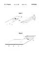
- FIG. 1is a perspective view of the electronic book of the present invention.
- FIG. 2is a perspective view of the electronic book of FIG. 1 partially opened to illustrate the pages, indicia thereon, and corresponding membrane switches located in the back cover.
- FIG. 2Ais a partial section view showing an alternate embodiment of a hole or cutout 68 in FIG. 2 to expose a membrane switch on the inside of the front cover.
- FIG. 3is a perspective exploded view illustrating the positions of the open cover, membrane switch insert, and a cosmetic "tail" cover.
- FIG. 4is a plan view of the cover after installation of a cover sheet on the back cover board and front cover board.
- FIG. 5is a perspective view illustrating attachment of fly sheets of a page assembly to the inside surfaces of the front and back covers after a membrane switch assembly has been positioned on the back cover.
- FIG. 5Ais a partial perspective view illustrating connection of the tail conductors to a printed circuit board inside the electronic module.
- FIG. 5Bis a section view taken along section lines 5B--5B of FIG. 5A.
- FIG. 6is a perspective view illustrating attachment of the electronic module onto a shelf section of the back cover.
- FIG. 6Ais a partial side view of the electronic book as shown in FIG. 6 with the pages fanned out.
- FIG. 6B-6Dare enlarged section views of detail 65 of FIG. 6A showing the book closed, partially open, and fully open, respectively.
- FIG. 7is a perspective exploded view of the opened membrane switch assembly, and each of three sequential patterns printed onto a MYLAR sheet to form the membrane switches of the present invention.
- FIG. 7Ais a tree diagram illustrating how the printed components of one membrane switch are combined according to the present invention.
- FIG. 7Bis a section view along section line 7B--7B of Fig.
- FIG. 7Cis a section view diagram similar to FIG. 7B, showing the membrane switch in un-actuated and actuated configurations.
- FIG. 8is a plan view of the membrane switches after all three conductor and insulator print patterns have been formed thereon, before folding the outer leaves.
- FIG. 9is a perspective view illustrating the membrane insert after the outer leaves have been folded and attached.
- FIG. 10is a schematic diagram of the circuitry contained in the electronic module to drive the speaker.
- electronic book 1shown “closed” in FIG. 1, includes a plurality of pages, collectively designated by numeral 4, connected between a back cover 2A and a front cover 2B.
- Back cover 2Ais extended beyond the upper edge of the book to support an electronic module 5 having a speaker 7 therein and a battery cover 6.
- each of the pages 4-1, 2 . . . 4has one or more indicia 12 on the "upper" surface thereof (meaning the upper surface when that page rests on back cover 2A).
- Dotted lines 9indicate which of various membrane switches 11 in a MYLAR membrane switch assembly 10 correspond to the various indicia 12 on a one-to-one basis.
- MYLAR membrane switch assembly 10composed of conventional 3-5 mil MYLAR sheet material, is affixed to the inside surface of back cover 2A and front cover 2B.
- no switch elementsare provided in or on the various pages 4.
- Each page 4has indicia 12 thereon. Any indicia 12 on any page 4 is aligned with only one membrane switch 11 when that page 4 lies flat on the back cover 2A or front cover 2B. Therefore, pressing on an indicia 12 of page 4 closes only one corresponding membrane switch 11.
- Row conductors 33 and column conductors 34are connected to an integrated circuit sound/voice chip 41 (FIG. 10) which causes a stored pattern of sounds, including words and/or music corresponding to the "pressed" indicia 12, to be emitted by speaker 7 (FIGS. 1 and 10).
- FIG. 2Ashows an alternate embodiment, in which a MYLAR membrane switch assembly 10 is attached to the inner surface of front cover 2B, so a membrane switch thereof aligned with cutout or hole 68 can be actuated by the prospective user. And, when the book is open, pressing any of indicia 12 on the opposite surfaces of the various sheets 41,2 etc. actuates membrane switches aligned therewith in the MYLAR membrane switch assembly 10 in the inner surface of front cover 2B.
- cover 2includes back cover 2A and front cover 2B connected to be "closed” along a center line 14.
- cover 2includes a back cover 2A composed of light cardboard, (such as 1200 gram DAVEY board), a similar front cover 2B, with 137 gram cover paper adhesively attached to the outer surface of front cover board 2B and back cover board 2B, and folded around the edges thereof to form fold strips 17A (FIG. 4).
- Cover paper 17can have artwork thereon and can be laminated to have a glossy surface.
- MYLAR switch assembly 10is attached to the inner surfaces of cover 2. Pages 4, when stitched and folded as shown, are positioned on the inner surfaces of MYLAR switch assembly 10 as indicated by dotted lines and arrows 20A and 20B in FIG. 5. Specifically, fly sheet 19A is glued to the inner surface of MYLAR switch assembly 10 over front cover 2B, and fly sheet 19B also is glued to the inside surface of MYLAR switch assembly 10 over back cover 2A. The various book pages are attached together by stitching them along their fold line 14A (FIG. 6) which is aligned with a center line 14 of cover 2, as shown in FIG. 4.
- MYLAR switch assembly 10includes a "tail” 15 which includes “tail” conductors 15A connected to each of the "x" conductors 33 and “y” conductors 34 (FIG. 8) respectively, in the rectangular array of membrane switches 11 in MYLAR membrane switch assembly 10.
- the terminals 44 of the integrated sound/voice chip 41(FIG. 10) are electronically connected as shown in FIGS. 5A and 5B to the ends of the various tail conductors 15A.
- a cosmetic cover or tape 16(FIG. 3) is positioned as indicated by arrows 21 to cover the conductors 15A on tail 15 except for their end terminal portions which are electrically connected to terminals 44 of sound/voice chip 41.
- arrow 54 in FIG. 5Agenerally indicates where tail 15, which includes tail portion 10A of MYLAR membrane switch assembly 10 and tail conductors 15A, is connected into electronic module 5.
- Electronic module 5includes an upper housing 5-1 having a vertical wall 5-2 and a number of interior posts 5-3 and 5-4, and socket 5-5.
- Electronic module 5also has a base section 71 that covers the open bottom of housing 5.
- Base section 71includes a slot 72 through which the tail 15 of MYLAR membrane switch assembly 10 extends.
- a recess 76is formed in base section 71, and a resilient insert 75 is positioned in recess 76.
- a pair of indexing posts 71-1extend upward from base section 71 into socket 5-5.
- the upper housing portion 5-1 of electronic module 5is preassembled to include an attached printed circuit board 74 including the circuitry shown in FIG. 10.
- Voice chip 41 of FIG. 10is bonded to the lower surface of printed circuit board 74, as are the terminals 44.
- a cavity 73 in base section 71provides clearance for chip 41.
- the various terminals 44are aligned immediately above exposed portions of corresponding tail conductors 15A to which they are electrically connected, respectively.
- the thickness of resilient pad 75is such that it urges the tail conductors 15A tightly into contact with the corresponding terminals 44.
- spaced parallel ridges 77 aligned with tail conductors 15Aare provided in the bottom of recess 76 (or on resilient pad 75) to concentrate the upward forces of resilient pad 75 onto the tail conductors 15A as much as possible.
- FIG. 6shows how electronic module 5 is attached to shelf 2C of back cover 2A.
- the electronic module 5includes the terminals 44 connected to the voice chip 41, as shown in FIG. 10. These terminals 44 are electrically connected to the various conductors on tail 15 and then the electronic module 5 is attached (by means of conventional adhesive) to the shelf portion 2C of back cover 2A.
- Spine 67is a composite structure formed of a portion 10F of MYLAR membrane switch layer 10 between the inner surfaces of back cover 2A and front cover 2B.
- the other portion of spine 67is a portion 17A of the cover paper 17 which is not attached to the outer surface of portion 10F of MYLAR membrane switch assembly 10.
- a volume 66 enclosed by spine 67accommodates the fold line portion 14 of the page assembly 4.
- spine structure 67An advantage of spine structure 67 is that the lower portion of the sheet of the MYLAR material used in the MYLAR membrane switch assembly is also used as the main hinge element, so no separate hinge or spine structure is needed. This lowers the cost of materials and facilitates the manufacturing process. Attachment of the components as previously described automatically creates the spine 67.
- the MYLAR hingeforms a much stronger spine than is present in conventional books.
- the hinge or spine section 67forms a gradual arc, and avoids the need for preforming a sharp crease in the MYLAR hinge that could cause cracking of conductors crossing the hinge or spine section 67.
- FIG. 7shows MYLAR sheet 10 with tab or tail section 10A on which the "tail" 15 including all of the tail conductors 15A are printed to provide the above described connections to corresponding terminals 44 of electronic module 5.
- Reference numeral 22indicates the first layer to be printed thereon in a first pass.
- Layer 22is a pattern of conventional conductive ink, and includes a central portion located between fold lines 10D and 10E and two outer portions formed on sections 10B and 10C.
- the first conductive pattern 22includes an array of individual "anode/cathode” patterns 27, one of which is shown in detail in FIG. 7A.
- each anode/cathode pattern 27includes a "cathode” portion 27A and an “anode” portion 27B.
- anodeone terminal is referred to as the "anode” and the other terminal is referred to as the "cathode", although this use of these terms is not intended to suggest any analogy between the membrane switch electrodes and the electrodes of a diode.
- Cathode portion 27Aincludes a single radial line 27A-1 which is connected to concentric partial rings 27A-2, 27A-3, and 27A-4, all of which are spaced from anode section 27B.
- Anode section 27Bincludes a single radial line 27B-1 which is electrically connected to concentric partial rings 27B-2, 27B-3, and complete ring 27B-4, all of which are concentric with and spaced from the partial rings of cathode portion 27A.
- First conductive pattern 22, formed in the first printing passincludes two arrays of cathode conductor-to-anode conductor electrical "shorting" patterns 26, one on section 10B of MYLAR sheet 10 and the other on section 10C thereof.
- One electrode shorting pattern 26is provided for each anode/cathode pattern 27.
- One of the conductive ink radial shorting patterns 26 formed during the first printing pass 22 in FIG. 7is shown in FIG. 7A.
- Each conductive shorting pattern 26includes a number of symmetrically positioned radial shorting leads 26A, all connected together at the center.
- the anode/cathode patterns 27are arranged in a matrix of rows and columns.
- the cathode portion 27A of each of the anode/cathode patterns in a particular columnare connected to a corresponding column conductor segment 34 that is routed as a tail conductor 15A to tail section 15 for connection to a corresponding terminal 44 of electronic module 5.
- the left column conductor 34-1is not segmented because it does not need to cross over any of the row conductors 33.
- the anode portion 27B of each of the anode/cathode patterns 27 in a particular rowis connected to a corresponding row conductor 33, which also is routed as a tail conductor 15A to tail section 15 for electrical connection to a corresponding terminal 44 of electronic module 5.
- a second printing passforms the insulative spacer pattern indicated by numeral 23 in FIG. 7, which can be composed of dielectrically insulative material.
- Insulative spacer pattern 23includes, in the center portion 10A of the sheet of which MYLAR membrane switch assembly 10 is composed, an array of insulative spacer rings 29 and corresponding insulative spacer dots 30 formed in the center of each spacer ring 29, respectively.
- Insulative pattern 23also includes an array of crossover spacers 31 (FIGS. 7 & 8) allowing the column conductor segments 34 to cross over the row conductors 33 in section 10A of MYLAR sheet 10 without shorting thereto.
- printed pattern 23includes an array of insulative spacer patterns 28.
- FIG. 7AOne such pattern 28 is shown in detail in FIG. 7A. It includes an outer spacer ring 28A, a number of generally radial lines 52, and a center spacer dot 53. (Note that the portions of insulative pattern 23 that merely function as spacers, rather than insulators, do not need to be of dielectric or insulative material.)
- the spacer ring/dot patterns 29,30are concentrically aligned with the corresponding anode/cathode patterns 27.
- the crossover dots 31are aligned with the "crossover intersections" of column conductor segments 34 and row conductors 33 as shown in FIGS. 7 and 8.
- Arrows 56, 57, 58 and 59 in FIG. 7Aillustrate precisely how corresponding anode/cathode conductive patterns 27, insulative spacer rings 29, shorting patterns 26, insulative dots 30, and insulative patterns 28 are aligned and superimposed to form the halves of individual membrane switches 11.
- a final printed patternindicated by numeral 24 in FIG. 7, includes a number of short "crossover" conductors 32 that connect the ends of column conductor segments 34 produced during the printing of pattern 22, allowing column conductor segments 34 of each column to form single column conductors that "cross over" row conductors 33.
- FIG. 7BA section view of one completed membrane switch 11 along section line 7B--7B of FIG. 7A is shown in FIG. 7B. It can be seen that the insulative spacer dots 30 and 53 and the spacer rings 28 and 29 formed on the portions 10A and 10B of MYLAR sheet 10 cause the radial shorting leads 26A to be positioned directly above and spaced from the cathode conductor rings 27A and the anode conductor rings 27B.
- FIG. 7Cshows how a membrane switch 11 is actuated.
- Portion “A” in FIG. 7Cshows a finger 63 aligned with membrane switch 11.
- finger 63presses on the folded MYLAR sheet portion 10B of membrane switch 11 (through the overlying pages 4, which are omitted for convenience of illustration), pressing the radial shorting leads 26A against the inter-leaved conductive anode and cathode rings 27A,B, thereby electrically shorting the cathode 27A of membrane switch 11 to the anode 27B thereof.
- Thiscauses the column conductor 34 and the row conductor 33 (FIG.
- FIG. 10shows a circuit schematic diagram of control module 5.
- Voice chip 41can be a model MSS6603, commercially available from Mosel-Vitelic Inc. of Taiwan and widely used in the electronics industry.
- Terminals 42 and 52 in FIG. 10are connected to the positive and negative terminals of a battery.
- Capacitor 47is a bypass capacitor.
- Output transistor 46has its base connected by conductor 50 to the audio output terminal C OUT of voice chip 41.
- the emitter of output transistor 46is connected by conductor 51 to the negative battery terminal.
- the collector of transistor 46is connected by conductor 45 to one terminal of speaker 7, the other terminal of which is connected by conductor 42 to the positive battery terminal.
- Resistor 43performs the function of controlling the internal clock frequency of voice chip 41.
- the various inputs of voice chip 41 connected to terminals 44allow voice chip 44 to identify which membrane switch 11 has been depressed and select a stored voice message corresponding to the pressed indicia 12 to be output to speaker 7.
- the above described embodiment of the electronic book of the present inventionincludes one or more of the switches 11 connected in parallel, so that they are, in effect, "wire-ORed". Therefore, if any of such parallel-connected or “duplicate” switches is actuated, the common row conductor 33 and column conductor 34 shared by such switches will be electrically shorted together, and hence will cause the same sequence of sounds to be generated by voice chip 41 as if any of such other parallel-connected switches is actuated.
- numeral 11-1is a "duplicate" switch that is connected in parallel with switch 11-2. As many duplicate switches can be provided as desired for a particular electronic book having a particular theme.
- segmented column conductors in conjunction with spot insulators 31 and jump conductors 32provides a substantial advantage by avoiding the need to provide insulative layers with via or "feed-through” holes to allow use of orthogonal row conductors 33 and column conductors 34.
- Use of orthogonal row and column conductorsallows "decoding at the switch level” and therefore greatly reduces the number of tail conductors 15A needed. It should be appreciated that it would be very difficult to provide as many switches as might be desired if each anode switch terminal and each cathode switch terminal had to be connected only to one corresponding tail conductor 15A. This would be the situation if the orthogonal row and column conductors 33 and 34 could not be inexpensively implemented; it is the use of spot insulators 31 and jump conductors 32 that achieves this economically.
- anode conductorsit may be desirable to connect only one or a few anode conductors to a particular tail conductor 15A and to correspondingly connect only one or a few cathode conductors to a particular tail conductor 15A.
- a particular preferred configurationis shown for the membrane switches 11, various other configurations of shorting pads could be used, and various other implementations of interleaved or even non-interleaved anode conductors and cathode conductors could be used.
- the insulative patternsalso could be considerably different than those disclosed.
Landscapes
- Engineering & Computer Science (AREA)
- Multimedia (AREA)
- Business, Economics & Management (AREA)
- Physics & Mathematics (AREA)
- Educational Administration (AREA)
- Educational Technology (AREA)
- General Physics & Mathematics (AREA)
- Theoretical Computer Science (AREA)
- Push-Button Switches (AREA)
Abstract
Description
Claims (25)
Priority Applications (1)
| Application Number | Priority Date | Filing Date | Title |
|---|---|---|---|
| US08/579,900US5810604A (en) | 1995-12-28 | 1995-12-28 | Electronic book and method |
Applications Claiming Priority (1)
| Application Number | Priority Date | Filing Date | Title |
|---|---|---|---|
| US08/579,900US5810604A (en) | 1995-12-28 | 1995-12-28 | Electronic book and method |
Publications (1)
| Publication Number | Publication Date |
|---|---|
| US5810604Atrue US5810604A (en) | 1998-09-22 |
Family
ID=24318806
Family Applications (1)
| Application Number | Title | Priority Date | Filing Date |
|---|---|---|---|
| US08/579,900Expired - LifetimeUS5810604A (en) | 1995-12-28 | 1995-12-28 | Electronic book and method |
Country Status (1)
| Country | Link |
|---|---|
| US (1) | US5810604A (en) |
Cited By (64)
| Publication number | Priority date | Publication date | Assignee | Title |
|---|---|---|---|---|
| WO1999024954A1 (en)* | 1997-11-10 | 1999-05-20 | Sims Barnes Wanda L | Literacy training device |
| US6021306A (en)* | 1989-08-21 | 2000-02-01 | Futech Interactive Products, Inc. | Apparatus for presenting visual material with identified sensory material |
| US6064855A (en)* | 1998-04-27 | 2000-05-16 | Ho; Frederick Pak Wai | Voice book system |
| WO2000074021A1 (en)* | 1999-05-26 | 2000-12-07 | Comfynet Ltd. | An interactive book particularly useful with computers |
| US6307168B1 (en)* | 1999-03-23 | 2001-10-23 | Paul Newham | Linear spaced dielectric dot separator pressure sensing array incorporating strain release stabilized releasable electric snap stud connectors |
| US6327459B2 (en)* | 1997-03-14 | 2001-12-04 | Tv Interactive Data Corporation | Remote control with a detachable insert |
| US6330427B1 (en) | 1999-09-08 | 2001-12-11 | Joel B. Tabachnik | Talking novelty device with book |
| US20020035697A1 (en)* | 2000-06-30 | 2002-03-21 | Mccurdy Kevin | Systems and methods for distributing and viewing electronic documents |
| US20020087555A1 (en)* | 2000-12-28 | 2002-07-04 | Casio Computer Co., Ltd. | Electronic book data delivery apparatus, electronic book device and recording medium |
| US6445378B1 (en)* | 1999-02-25 | 2002-09-03 | William F Flagg | Mouse pad for initiating or controlling software applications |
| US6448518B1 (en)* | 2001-06-11 | 2002-09-10 | Delphi Technologies, Inc. | Resistive switch pad |
| US6479775B2 (en)* | 2000-05-31 | 2002-11-12 | Alps Electric Co., Ltd. | Flat input device having push switches |
| WO2002093530A1 (en)* | 2001-05-11 | 2002-11-21 | Shoot The Moon Products Ii, Llc | Interactive book reading system using rf scanning circuit |
| US6516181B1 (en)* | 2001-07-25 | 2003-02-04 | Debbie Giampapa Kirwan | Interactive picture book with voice recording features and method of use |
| US6549751B1 (en) | 2000-07-25 | 2003-04-15 | Giuseppe Li Mandri | Multimedia educational system |
| US6578436B1 (en)* | 2000-05-16 | 2003-06-17 | Fidelica Microsystems, Inc. | Method and apparatus for pressure sensing |
| US20030116620A1 (en)* | 1999-08-09 | 2003-06-26 | Jin Song | Method and system for illustrating sound and text |
| US6590177B2 (en)* | 2001-06-01 | 2003-07-08 | Fujikura Ltd. | Membrane switch and pressure sensitive sensor |
| US6636203B1 (en)* | 2001-05-17 | 2003-10-21 | Palm, Inc. | Keyboard equivalent pad overlay encasement for a handheld electronic device |
| US6650867B2 (en)* | 1997-03-14 | 2003-11-18 | Smartpaper Networks Corporation | Remote control apparatus and method of transmitting data to a host device |
| US20030219703A1 (en)* | 2002-05-24 | 2003-11-27 | Basconi Edward A. | Hands on instruction manual |
| WO2003102895A1 (en)* | 2002-05-30 | 2003-12-11 | Mattel, Inc. | Interactive multi-sensory reading system electronic teaching/learning device |
| WO2003102898A1 (en)* | 2002-05-30 | 2003-12-11 | Mattel, Inc. | An electronic learning device for an interactive muti-sensory reading system |
| US20040021648A1 (en)* | 2002-07-31 | 2004-02-05 | Leo Blume | System for enhancing books |
| US20040023200A1 (en)* | 2002-07-31 | 2004-02-05 | Leo Blume | System for enhancing books with special paper |
| US6697039B1 (en)* | 1999-02-24 | 2004-02-24 | Minolta Co., Ltd. | Information displaying apparatus |
| US20040043365A1 (en)* | 2002-05-30 | 2004-03-04 | Mattel, Inc. | Electronic learning device for an interactive multi-sensory reading system |
| US20040163939A1 (en)* | 2003-02-20 | 2004-08-26 | Iee International Electronics & Engineering S.A. | Foil-type switching element with improved spacer design |
| US20040173447A1 (en)* | 2003-03-04 | 2004-09-09 | Young-Woo Lee | Membrane switch and its application to acoustic strip wallpaper and picture board |
| US20050076548A1 (en)* | 2003-09-05 | 2005-04-14 | Devos John A. | Printed sensor having opposed areas of nonvisible conductive ink |
| US20050156902A1 (en)* | 2004-01-20 | 2005-07-21 | Mcpherson Roger | Electronic tablet |
| US20050223818A1 (en)* | 2000-05-16 | 2005-10-13 | Deconde Keith T | Method and apparatus for protection of contour sensing devices |
| US7006116B1 (en)* | 1999-11-16 | 2006-02-28 | Nokia Corporation | Tangibly encoded media identification in a book cover |
| US7030329B1 (en)* | 2004-10-22 | 2006-04-18 | Solectron Invotronics | Switch contact |
| US20070013680A1 (en)* | 2003-12-19 | 2007-01-18 | Yeung Minerva M | Electronic pen-computer multimedia interactive system |
| US20070051609A1 (en)* | 2005-09-02 | 2007-03-08 | Wayne Parkinson | Switches and systems employing the same to enhance switch reliability and control |
| US20070093169A1 (en)* | 2005-10-20 | 2007-04-26 | Blaszczyk Abbey C | Interactive book and toy |
| USD545769S1 (en)* | 2006-02-17 | 2007-07-03 | Stora Enso Ab | Switch |
| US20070164994A1 (en)* | 2006-01-18 | 2007-07-19 | Takefumi Inoue | Input device |
| US20070243514A1 (en)* | 2006-04-13 | 2007-10-18 | Thomas Tyren S | Educational book |
| US20070278082A1 (en)* | 2005-09-02 | 2007-12-06 | Wayne Parkinson | Switch arrays and systems employing the same to enhance system reliability |
| US20080105528A1 (en)* | 2006-11-07 | 2008-05-08 | Ngoc Minh Luong | Key for an electronic keyboard |
| US7428990B1 (en)* | 2004-12-22 | 2008-09-30 | Leapfrog Enterprises, Inc. | Capacitive sensing of media information in an interactive media device |
| US20080254428A1 (en)* | 2003-01-31 | 2008-10-16 | Mattel, Inc. | Interactive electronic device with optical page identification system |
| US20090050464A1 (en)* | 2007-08-23 | 2009-02-26 | Nintendo Co., Ltd. | Key switch, input device, contact pattern |
| US7621441B1 (en) | 2004-12-22 | 2009-11-24 | Leapfrog Enterprises | Interactive device using capacitive sensor array for joint page identification and page location determination |
| US20100066071A1 (en)* | 2006-06-22 | 2010-03-18 | Emmanouil Kelaidis | Bluebook |
| US20100149796A1 (en)* | 2008-12-17 | 2010-06-17 | Patrick Mish | BOOKLIGHT FOR A PROTECTIVE COVER OF AN eREADER |
| US8025505B2 (en) | 2003-02-10 | 2011-09-27 | Leapfrog Enterprises, Inc. | Interactive hand held apparatus with stylus |
| US20120123889A1 (en)* | 2010-10-26 | 2012-05-17 | Mosquera Luis D | System and method for streamlined acquisition, download and opening of digital content |
| GB2501689A (en)* | 2012-04-30 | 2013-11-06 | Novalia Ltd | Printed article acoustically coupled to electronic device |
| GB2506862A (en)* | 2012-10-09 | 2014-04-16 | Novalia Ltd | Book with capacitive touch pad in at least one cover |
| EP2728568A1 (en)* | 2012-10-31 | 2014-05-07 | Leo Paper Bags Manufacturing (1982) Limited | Changeable book assembly |
| US20140225837A1 (en)* | 2013-02-12 | 2014-08-14 | Illinois Tool Works, Inc. | Front Panel Overlay Incorporating a Logic Circuit |
| WO2015048044A1 (en)* | 2013-09-27 | 2015-04-02 | Osram Sylvania Inc. | Flexible circuit board for electronic applications, light source containing same, and method of making |
| US20150227803A1 (en)* | 2012-08-24 | 2015-08-13 | Moleskine S.P.A. | Notebook and method for digitizing notes |
| US20160109976A1 (en)* | 2014-10-16 | 2016-04-21 | Hallmark Cards, Incorporated | Capacitive gesture recognition book |
| US20160148521A1 (en)* | 2011-04-11 | 2016-05-26 | Ali Mohammad Bujsaim | Sensitivity adjustment for talking book |
| US9489856B2 (en) | 2012-05-23 | 2016-11-08 | SmartBound Technologies, LLC | Interactive printed article with touch-activated presentation |
| US20170098391A1 (en)* | 2015-10-06 | 2017-04-06 | Tsui-Chhiung Wu | Learning card |
| US9646584B1 (en)* | 2015-12-15 | 2017-05-09 | Chris Dorety | Visual aid for improvised music |
| US20170186565A1 (en)* | 2015-12-24 | 2017-06-29 | Jiangsu Transimage Technology Co., Ltd | Thin-film switch |
| US10459584B2 (en)* | 2018-02-09 | 2019-10-29 | Asianlink Technology Incorporation | Electronic book with touch sensing and page number detection |
| US11610499B2 (en) | 2018-03-26 | 2023-03-21 | Hewlett-Packard Development Company, L.P. | Printed circuitry |
Citations (16)
| Publication number | Priority date | Publication date | Assignee | Title |
|---|---|---|---|---|
| US4389711A (en)* | 1979-08-17 | 1983-06-21 | Hitachi, Ltd. | Touch sensitive tablet using force detection |
| US4564079A (en)* | 1984-07-30 | 1986-01-14 | Koala Technologies Corporation | Digitizer pad |
| US4570149A (en)* | 1983-03-15 | 1986-02-11 | Koala Technologies Corporation | Simplified touch tablet data device |
| US4706536A (en)* | 1986-02-05 | 1987-11-17 | Jtg Of Nashville, Inc. | Membrane keyboard for songbook tone generator |
| US4752230A (en)* | 1986-05-02 | 1988-06-21 | Dainippon Kaiga Co., Ltd. | Picture book |
| US4778391A (en)* | 1986-01-26 | 1988-10-18 | Weiner Avish J | Sound-producing amusement or educational devices |
| US4809246A (en)* | 1987-04-24 | 1989-02-28 | Lih Jeng | Sound illustrated book having page indicator circuit |
| US4818827A (en)* | 1988-04-07 | 1989-04-04 | Amp Incorporated | Low force membrane switch |
| US4990092A (en)* | 1989-08-14 | 1991-02-05 | Tonka Corporation | Talking book |
| WO1992018964A1 (en)* | 1991-04-14 | 1992-10-29 | Mctaggart Stephen I | Electronic book |
| US5209665A (en)* | 1989-10-12 | 1993-05-11 | Sight & Sound Incorporated | Interactive audio visual work |
| US5290190A (en)* | 1992-09-30 | 1994-03-01 | Mcclanahan Susan D | Talking book |
| US5356296A (en)* | 1992-07-08 | 1994-10-18 | Harold D. Pierce | Audio storybook |
| US5374195A (en)* | 1992-09-30 | 1994-12-20 | Mcclanahan Book Company, Inc. | Talking book |
| US5437552A (en)* | 1993-08-13 | 1995-08-01 | Western Publishing Co., Inc. | Interactive audio-visual work |
| US5484292A (en)* | 1989-08-21 | 1996-01-16 | Mctaggart; Stephen I. | Apparatus for combining audio and visual indicia |
- 1995
- 1995-12-28USUS08/579,900patent/US5810604A/ennot_activeExpired - Lifetime
Patent Citations (19)
| Publication number | Priority date | Publication date | Assignee | Title |
|---|---|---|---|---|
| US4389711A (en)* | 1979-08-17 | 1983-06-21 | Hitachi, Ltd. | Touch sensitive tablet using force detection |
| US4570149A (en)* | 1983-03-15 | 1986-02-11 | Koala Technologies Corporation | Simplified touch tablet data device |
| US4564079A (en)* | 1984-07-30 | 1986-01-14 | Koala Technologies Corporation | Digitizer pad |
| US4778391A (en)* | 1986-01-26 | 1988-10-18 | Weiner Avish J | Sound-producing amusement or educational devices |
| US4706536A (en)* | 1986-02-05 | 1987-11-17 | Jtg Of Nashville, Inc. | Membrane keyboard for songbook tone generator |
| US4752230A (en)* | 1986-05-02 | 1988-06-21 | Dainippon Kaiga Co., Ltd. | Picture book |
| US4809246A (en)* | 1987-04-24 | 1989-02-28 | Lih Jeng | Sound illustrated book having page indicator circuit |
| US4818827A (en)* | 1988-04-07 | 1989-04-04 | Amp Incorporated | Low force membrane switch |
| US4990092A (en)* | 1989-08-14 | 1991-02-05 | Tonka Corporation | Talking book |
| US4990092B1 (en)* | 1989-08-14 | 1998-08-04 | Tonka Corp | Talking book |
| US5417575A (en)* | 1989-08-21 | 1995-05-23 | Mctaggart; Stephen I. | Electronic book |
| US5484292A (en)* | 1989-08-21 | 1996-01-16 | Mctaggart; Stephen I. | Apparatus for combining audio and visual indicia |
| US5209665A (en)* | 1989-10-12 | 1993-05-11 | Sight & Sound Incorporated | Interactive audio visual work |
| US5453013A (en)* | 1989-10-12 | 1995-09-26 | Western Publishing Co., Inc. | Interactive audio visual work |
| WO1992018964A1 (en)* | 1991-04-14 | 1992-10-29 | Mctaggart Stephen I | Electronic book |
| US5356296A (en)* | 1992-07-08 | 1994-10-18 | Harold D. Pierce | Audio storybook |
| US5290190A (en)* | 1992-09-30 | 1994-03-01 | Mcclanahan Susan D | Talking book |
| US5374195A (en)* | 1992-09-30 | 1994-12-20 | Mcclanahan Book Company, Inc. | Talking book |
| US5437552A (en)* | 1993-08-13 | 1995-08-01 | Western Publishing Co., Inc. | Interactive audio-visual work |
Cited By (125)
| Publication number | Priority date | Publication date | Assignee | Title |
|---|---|---|---|---|
| US6021306A (en)* | 1989-08-21 | 2000-02-01 | Futech Interactive Products, Inc. | Apparatus for presenting visual material with identified sensory material |
| US6650867B2 (en)* | 1997-03-14 | 2003-11-18 | Smartpaper Networks Corporation | Remote control apparatus and method of transmitting data to a host device |
| US6968151B2 (en) | 1997-03-14 | 2005-11-22 | Smartpaper Networks Corporation | Remote control |
| US20050255435A1 (en)* | 1997-03-14 | 2005-11-17 | Redford Peter M | Insert for use with a remote control base |
| US6327459B2 (en)* | 1997-03-14 | 2001-12-04 | Tv Interactive Data Corporation | Remote control with a detachable insert |
| US20040086840A1 (en)* | 1997-03-14 | 2004-05-06 | Redford Peter M. | Method of detachably attaching an insert to a remote control base and the resulting remot control |
| WO1999024954A1 (en)* | 1997-11-10 | 1999-05-20 | Sims Barnes Wanda L | Literacy training device |
| US5975910A (en)* | 1997-11-10 | 1999-11-02 | Sims-Barnes; Wanda L. | Literacy training device |
| US6064855A (en)* | 1998-04-27 | 2000-05-16 | Ho; Frederick Pak Wai | Voice book system |
| US6697039B1 (en)* | 1999-02-24 | 2004-02-24 | Minolta Co., Ltd. | Information displaying apparatus |
| US6445378B1 (en)* | 1999-02-25 | 2002-09-03 | William F Flagg | Mouse pad for initiating or controlling software applications |
| US6307168B1 (en)* | 1999-03-23 | 2001-10-23 | Paul Newham | Linear spaced dielectric dot separator pressure sensing array incorporating strain release stabilized releasable electric snap stud connectors |
| WO2000074021A1 (en)* | 1999-05-26 | 2000-12-07 | Comfynet Ltd. | An interactive book particularly useful with computers |
| US7290700B2 (en) | 1999-08-09 | 2007-11-06 | Pil, L.L.C. | Method and system for illustrating sound and text |
| US20080067231A1 (en)* | 1999-08-09 | 2008-03-20 | Publications International, Ltd. | Method and system for illustrating sound and text |
| US7111774B2 (en) | 1999-08-09 | 2006-09-26 | Pil, L.L.C. | Method and system for illustrating sound and text |
| US6763995B1 (en)* | 1999-08-09 | 2004-07-20 | Pil, L.L.C. | Method and system for illustrating sound and text |
| US7540406B2 (en)* | 1999-08-09 | 2009-06-02 | Publications International, Ltd. | Method and system for illustrating sound and text |
| US20030116620A1 (en)* | 1999-08-09 | 2003-06-26 | Jin Song | Method and system for illustrating sound and text |
| US20060191992A1 (en)* | 1999-08-09 | 2006-08-31 | Publications International, Ltd. | Method and system for illustrating sound and text |
| US20040178256A1 (en)* | 1999-08-09 | 2004-09-16 | Pil, L.L.C. | Method and system for illustrating sound and text |
| US7201317B2 (en) | 1999-08-09 | 2007-04-10 | Pil, L.L.C. | Method and system for illustrating sound and text |
| US20040016809A1 (en)* | 1999-08-09 | 2004-01-29 | Song Jin K. | Method and system for illustrating sound and text |
| US6330427B1 (en) | 1999-09-08 | 2001-12-11 | Joel B. Tabachnik | Talking novelty device with book |
| US7006116B1 (en)* | 1999-11-16 | 2006-02-28 | Nokia Corporation | Tangibly encoded media identification in a book cover |
| US7437953B2 (en) | 2000-05-16 | 2008-10-21 | Deconde Keith T | Method and apparatus for protection of contour sensing devices |
| US20050229380A1 (en)* | 2000-05-16 | 2005-10-20 | Deconde Keith T | Fingerprint sensors using membrane switch arrays |
| US20050223818A1 (en)* | 2000-05-16 | 2005-10-13 | Deconde Keith T | Method and apparatus for protection of contour sensing devices |
| US7316167B2 (en) | 2000-05-16 | 2008-01-08 | Fidelica, Microsystems, Inc. | Method and apparatus for protection of contour sensing devices |
| US7638350B2 (en) | 2000-05-16 | 2009-12-29 | Springworks Llc | Fingerprint sensors using membrane switch arrays |
| US6889565B2 (en) | 2000-05-16 | 2005-05-10 | Fidelica Microsystems, Inc. | Fingerprint sensors using membrane switch arrays |
| US6578436B1 (en)* | 2000-05-16 | 2003-06-17 | Fidelica Microsystems, Inc. | Method and apparatus for pressure sensing |
| US6829950B2 (en) | 2000-05-16 | 2004-12-14 | Fidelica Microsystems, Inc. | Method and apparatus for pressure sensing |
| US20070289392A1 (en)* | 2000-05-16 | 2007-12-20 | Fidelica Microsystems, Inc. | Method and apparatus for protection of contour sensing devices |
| US6479775B2 (en)* | 2000-05-31 | 2002-11-12 | Alps Electric Co., Ltd. | Flat input device having push switches |
| US8561205B2 (en) | 2000-06-30 | 2013-10-15 | Zinio, Llc | Systems and methods for distributing and viewing electronic documents |
| US20020035697A1 (en)* | 2000-06-30 | 2002-03-21 | Mccurdy Kevin | Systems and methods for distributing and viewing electronic documents |
| US7290285B2 (en) | 2000-06-30 | 2007-10-30 | Zinio Systems, Inc. | Systems and methods for distributing and viewing electronic documents |
| US20080082903A1 (en)* | 2000-06-30 | 2008-04-03 | Zinio Systems, Inc. | Systems and methods for distributing and viewing electronic documents |
| US6549751B1 (en) | 2000-07-25 | 2003-04-15 | Giuseppe Li Mandri | Multimedia educational system |
| US6985913B2 (en)* | 2000-12-28 | 2006-01-10 | Casio Computer Co. Ltd. | Electronic book data delivery apparatus, electronic book device and recording medium |
| US20020087555A1 (en)* | 2000-12-28 | 2002-07-04 | Casio Computer Co., Ltd. | Electronic book data delivery apparatus, electronic book device and recording medium |
| WO2002093530A1 (en)* | 2001-05-11 | 2002-11-21 | Shoot The Moon Products Ii, Llc | Interactive book reading system using rf scanning circuit |
| US20040219501A1 (en)* | 2001-05-11 | 2004-11-04 | Shoot The Moon Products Ii, Llc Et Al. | Interactive book reading system using RF scanning circuit |
| AU2002309702B2 (en)* | 2001-05-11 | 2008-01-17 | Shoot The Moon Products Ii, Llc | Interactive book reading system using RF scanning circuit |
| US7941090B2 (en) | 2001-05-11 | 2011-05-10 | Shoot The Moon Products Ii, Llc | Interactive book reading system using RF scanning circuit |
| US6636203B1 (en)* | 2001-05-17 | 2003-10-21 | Palm, Inc. | Keyboard equivalent pad overlay encasement for a handheld electronic device |
| US6590177B2 (en)* | 2001-06-01 | 2003-07-08 | Fujikura Ltd. | Membrane switch and pressure sensitive sensor |
| US6448518B1 (en)* | 2001-06-11 | 2002-09-10 | Delphi Technologies, Inc. | Resistive switch pad |
| US20030113696A1 (en)* | 2001-07-25 | 2003-06-19 | Kirwan Debra Giampapa | Interactive picture book with voice recording features and method of use |
| US6985693B2 (en)* | 2001-07-25 | 2006-01-10 | Debra Giampapa Kirwan | Interactive picture book with voice recording features and method of use |
| US6516181B1 (en)* | 2001-07-25 | 2003-02-04 | Debbie Giampapa Kirwan | Interactive picture book with voice recording features and method of use |
| US20030219703A1 (en)* | 2002-05-24 | 2003-11-27 | Basconi Edward A. | Hands on instruction manual |
| US6910894B2 (en)* | 2002-05-24 | 2005-06-28 | Edward A. Basconi | Hands on instruction manual |
| WO2003102895A1 (en)* | 2002-05-30 | 2003-12-11 | Mattel, Inc. | Interactive multi-sensory reading system electronic teaching/learning device |
| WO2003102898A1 (en)* | 2002-05-30 | 2003-12-11 | Mattel, Inc. | An electronic learning device for an interactive muti-sensory reading system |
| US20070190511A1 (en)* | 2002-05-30 | 2007-08-16 | Mattel, Inc. | Interactive Multi-Sensory Reading System Electronic Teaching/Learning Device |
| US20040043365A1 (en)* | 2002-05-30 | 2004-03-04 | Mattel, Inc. | Electronic learning device for an interactive multi-sensory reading system |
| US7402042B2 (en) | 2002-05-30 | 2008-07-22 | Mattel, Inc. | Electronic learning device for an interactive multi-sensory reading system |
| US7203455B2 (en) | 2002-05-30 | 2007-04-10 | Mattel, Inc. | Interactive multi-sensory reading system electronic teaching/learning device |
| US20040043371A1 (en)* | 2002-05-30 | 2004-03-04 | Ernst Stephen M. | Interactive multi-sensory reading system electronic teaching/learning device |
| US20040021648A1 (en)* | 2002-07-31 | 2004-02-05 | Leo Blume | System for enhancing books |
| US7081885B2 (en) | 2002-07-31 | 2006-07-25 | Hewlett-Packard Development Company, L.P. | System for enhancing books |
| US20040023200A1 (en)* | 2002-07-31 | 2004-02-05 | Leo Blume | System for enhancing books with special paper |
| US6915103B2 (en) | 2002-07-31 | 2005-07-05 | Hewlett-Packard Development Company, L.P. | System for enhancing books with special paper |
| US20080254428A1 (en)* | 2003-01-31 | 2008-10-16 | Mattel, Inc. | Interactive electronic device with optical page identification system |
| US20110236869A1 (en)* | 2003-01-31 | 2011-09-29 | Mattel, Inc. | Interactive electronic device with optical page identification system |
| US8594557B2 (en) | 2003-01-31 | 2013-11-26 | Mattel, Inc. | Interactive electronic device with optical page identification system |
| US8025505B2 (en) | 2003-02-10 | 2011-09-27 | Leapfrog Enterprises, Inc. | Interactive hand held apparatus with stylus |
| US20040163939A1 (en)* | 2003-02-20 | 2004-08-26 | Iee International Electronics & Engineering S.A. | Foil-type switching element with improved spacer design |
| US7187264B2 (en)* | 2003-02-20 | 2007-03-06 | Iee International Electronics & Engineering S.A. | Foil-type switching element with improved spacer design |
| US20040173447A1 (en)* | 2003-03-04 | 2004-09-09 | Young-Woo Lee | Membrane switch and its application to acoustic strip wallpaper and picture board |
| US20050076548A1 (en)* | 2003-09-05 | 2005-04-14 | Devos John A. | Printed sensor having opposed areas of nonvisible conductive ink |
| US7106208B2 (en) | 2003-09-05 | 2006-09-12 | Hewlett-Packard Development Company, L.P. | Printed sensor having opposed areas of nonvisible conductive ink |
| US20070013680A1 (en)* | 2003-12-19 | 2007-01-18 | Yeung Minerva M | Electronic pen-computer multimedia interactive system |
| US20050156902A1 (en)* | 2004-01-20 | 2005-07-21 | Mcpherson Roger | Electronic tablet |
| US20060086598A1 (en)* | 2004-10-22 | 2006-04-27 | Brian Sneek | Switch contact |
| US7030329B1 (en)* | 2004-10-22 | 2006-04-18 | Solectron Invotronics | Switch contact |
| US8267309B1 (en) | 2004-12-22 | 2012-09-18 | Leapfrog Enterprises, Inc. | Interactive device using capacitive sensor array for joint page identification and page location determination |
| US7621441B1 (en) | 2004-12-22 | 2009-11-24 | Leapfrog Enterprises | Interactive device using capacitive sensor array for joint page identification and page location determination |
| US7428990B1 (en)* | 2004-12-22 | 2008-09-30 | Leapfrog Enterprises, Inc. | Capacitive sensing of media information in an interactive media device |
| US7417202B2 (en)* | 2005-09-02 | 2008-08-26 | White Electronic Designs Corporation | Switches and systems employing the same to enhance switch reliability and control |
| US7439465B2 (en) | 2005-09-02 | 2008-10-21 | White Electronics Designs Corporation | Switch arrays and systems employing the same to enhance system reliability |
| US20070051609A1 (en)* | 2005-09-02 | 2007-03-08 | Wayne Parkinson | Switches and systems employing the same to enhance switch reliability and control |
| US20070278082A1 (en)* | 2005-09-02 | 2007-12-06 | Wayne Parkinson | Switch arrays and systems employing the same to enhance system reliability |
| US20070093169A1 (en)* | 2005-10-20 | 2007-04-26 | Blaszczyk Abbey C | Interactive book and toy |
| US8339368B2 (en)* | 2006-01-18 | 2012-12-25 | Panasonic Corporation | Input device |
| US20070164994A1 (en)* | 2006-01-18 | 2007-07-19 | Takefumi Inoue | Input device |
| USD545769S1 (en)* | 2006-02-17 | 2007-07-03 | Stora Enso Ab | Switch |
| USD560171S1 (en)* | 2006-02-17 | 2008-01-22 | Stora Enso Ab | Switch |
| US20070243514A1 (en)* | 2006-04-13 | 2007-10-18 | Thomas Tyren S | Educational book |
| US20100066071A1 (en)* | 2006-06-22 | 2010-03-18 | Emmanouil Kelaidis | Bluebook |
| US7763815B2 (en)* | 2006-11-07 | 2010-07-27 | Symbol Technologies, Inc. | Key for an electronic keyboard |
| US20080105528A1 (en)* | 2006-11-07 | 2008-05-08 | Ngoc Minh Luong | Key for an electronic keyboard |
| US7915547B2 (en)* | 2007-08-23 | 2011-03-29 | Nintendo Co., Ltd. | Key switch, input device, contact pattern |
| US20090050464A1 (en)* | 2007-08-23 | 2009-02-26 | Nintendo Co., Ltd. | Key switch, input device, contact pattern |
| US8186843B2 (en) | 2008-12-17 | 2012-05-29 | M-Edge Accessories, Llc | Booklight for a protective cover of an eReader |
| US20110069475A1 (en)* | 2008-12-17 | 2011-03-24 | M-Edge Accessories, Llc | BOOKLIGHT FOR A PROTECTIVE COVER OF AN eREADER |
| US8047670B2 (en)* | 2008-12-17 | 2011-11-01 | M-Edge Accessories, Llc | Booklight for a protective cover of an eReader |
| US20100149796A1 (en)* | 2008-12-17 | 2010-06-17 | Patrick Mish | BOOKLIGHT FOR A PROTECTIVE COVER OF AN eREADER |
| US20120123889A1 (en)* | 2010-10-26 | 2012-05-17 | Mosquera Luis D | System and method for streamlined acquisition, download and opening of digital content |
| US20160148521A1 (en)* | 2011-04-11 | 2016-05-26 | Ali Mohammad Bujsaim | Sensitivity adjustment for talking book |
| GB2501689A (en)* | 2012-04-30 | 2013-11-06 | Novalia Ltd | Printed article acoustically coupled to electronic device |
| US9529461B2 (en) | 2012-04-30 | 2016-12-27 | Novalia Ltd | Printed article |
| GB2501689B (en)* | 2012-04-30 | 2016-10-19 | Novalia Ltd | Printed article |
| US9489856B2 (en) | 2012-05-23 | 2016-11-08 | SmartBound Technologies, LLC | Interactive printed article with touch-activated presentation |
| US20150227803A1 (en)* | 2012-08-24 | 2015-08-13 | Moleskine S.P.A. | Notebook and method for digitizing notes |
| US9235772B2 (en)* | 2012-08-24 | 2016-01-12 | Moleskine S.P.A. | Notebook and method for digitizing notes |
| CN104838435A (en)* | 2012-10-09 | 2015-08-12 | 诺瓦利亚公司 | Book with detachable cover |
| GB2506862B (en)* | 2012-10-09 | 2015-08-12 | Novalia Ltd | Book |
| GB2506862A (en)* | 2012-10-09 | 2014-04-16 | Novalia Ltd | Book with capacitive touch pad in at least one cover |
| CN109032462A (en)* | 2012-10-09 | 2018-12-18 | 诺瓦利亚公司 | Book, method, computer program and computer-readable medium |
| EP2728568A1 (en)* | 2012-10-31 | 2014-05-07 | Leo Paper Bags Manufacturing (1982) Limited | Changeable book assembly |
| US9996173B2 (en)* | 2013-02-12 | 2018-06-12 | Illinois Tool Works, Inc. | Front panel overlay incorporating a logic circuit |
| US20140225837A1 (en)* | 2013-02-12 | 2014-08-14 | Illinois Tool Works, Inc. | Front Panel Overlay Incorporating a Logic Circuit |
| US9335034B2 (en) | 2013-09-27 | 2016-05-10 | Osram Sylvania Inc | Flexible circuit board for electronic applications, light source containing same, and method of making |
| WO2015048044A1 (en)* | 2013-09-27 | 2015-04-02 | Osram Sylvania Inc. | Flexible circuit board for electronic applications, light source containing same, and method of making |
| US20160109976A1 (en)* | 2014-10-16 | 2016-04-21 | Hallmark Cards, Incorporated | Capacitive gesture recognition book |
| US10643484B2 (en)* | 2014-10-16 | 2020-05-05 | Hallmark Cards, Incorporated | Capacitive gesture recognition book |
| US20170098391A1 (en)* | 2015-10-06 | 2017-04-06 | Tsui-Chhiung Wu | Learning card |
| US9646584B1 (en)* | 2015-12-15 | 2017-05-09 | Chris Dorety | Visual aid for improvised music |
| US20170186565A1 (en)* | 2015-12-24 | 2017-06-29 | Jiangsu Transimage Technology Co., Ltd | Thin-film switch |
| US9741501B2 (en)* | 2015-12-24 | 2017-08-22 | Jiangsu Transimage Technology Co., Ltd. | Thin-film switch |
| US10459584B2 (en)* | 2018-02-09 | 2019-10-29 | Asianlink Technology Incorporation | Electronic book with touch sensing and page number detection |
| US11610499B2 (en) | 2018-03-26 | 2023-03-21 | Hewlett-Packard Development Company, L.P. | Printed circuitry |
Similar Documents
| Publication | Publication Date | Title |
|---|---|---|
| US5810604A (en) | Electronic book and method | |
| US6041215A (en) | Method for making an electronic book for producing audible sounds in response to visual indicia | |
| US5609488A (en) | Method of combining audio and visual indicia | |
| US5167508A (en) | Electronic book | |
| WO1994012963A2 (en) | Electronic book | |
| US20080254428A1 (en) | Interactive electronic device with optical page identification system | |
| JPS59229915A (en) | Thick film delay line and method of producing same | |
| GB2226903A (en) | Keyboard capacitance membrane switchcore | |
| US4876461A (en) | Self-referencing capacitive key cell structure and switchcore matrices formed therefrom | |
| US20110169257A1 (en) | Book | |
| US4677529A (en) | Circuit board | |
| WO2004023429A2 (en) | Compact book and apparatus using print media | |
| US4694126A (en) | Membrane keyboard switch assembly having spacer structure and method of making | |
| WO1998022987A9 (en) | Laminated sheet product containing a printed battery | |
| US20120187952A1 (en) | Capacitive Page Opening Detector | |
| GB2487576A (en) | Printed book | |
| JPH11185565A (en) | Membrane switch | |
| WO1997001857A1 (en) | Improvements relating to pressure pads | |
| JPH076579Y2 (en) | Keyboard system | |
| CN202331860U (en) | Simple right-or-wrong answer machine and answer sheet | |
| JPS5839379A (en) | Tablet for information input equipment | |
| JPS6146552Y2 (en) | ||
| JPH0310356B2 (en) | ||
| JPS62153998A (en) | After touch switch gear for keyboard unit of electronic musical apparatus | |
| JPS62197906A (en) | Magnetic head |
Legal Events
| Date | Code | Title | Description |
|---|---|---|---|
| STCF | Information on status: patent grant | Free format text:PATENTED CASE | |
| FEPP | Fee payment procedure | Free format text:PAYOR NUMBER ASSIGNED (ORIGINAL EVENT CODE: ASPN); ENTITY STATUS OF PATENT OWNER: SMALL ENTITY | |
| FPAY | Fee payment | Year of fee payment:4 | |
| AS | Assignment | Owner name:WILLIAMS, DERRILL, ARIZONA Free format text:ASSIGNMENT OF ASSIGNORS INTEREST;ASSIGNOR:PIONEER PUBLISHING;REEL/FRAME:013463/0101 Effective date:20021017 | |
| AS | Assignment | Owner name:FUTECH EDUCATIONAL PRODUCTS, INC., ARIZONA Free format text:ASSIGNMENT OF ASSIGNORS INTEREST;ASSIGNORS:KOPP, RICHARD L.;KOPP, DEBORAH A.;REEL/FRAME:014384/0334 Effective date:19980119 Owner name:FUTECH INTERACTIVE PRODUCTS, INC., ARIZONA Free format text:CHANGE OF NAME;ASSIGNOR:FUTECH EDUCATIONAL PRODUCTS, INC.;REEL/FRAME:014384/0504 Effective date:19980206 | |
| AS | Assignment | Owner name:PAGE TOUCH TECHNOLOGIES, LLC, ARIZONA Free format text:ASSIGNMENT OF ASSIGNORS INTEREST;ASSIGNOR:WILLIAMS, DERRILL;REEL/FRAME:017448/0267 Effective date:20051212 | |
| FPAY | Fee payment | Year of fee payment:8 | |
| FPAY | Fee payment | Year of fee payment:12 |