US5810461A - Methods and apparatus for organizing the electric cables of peripheral equipment attached to a computer housing - Google Patents
Methods and apparatus for organizing the electric cables of peripheral equipment attached to a computer housingDownload PDFInfo
- Publication number
- US5810461A US5810461AUS08/779,742US77974297AUS5810461AUS 5810461 AUS5810461 AUS 5810461AUS 77974297 AUS77974297 AUS 77974297AUS 5810461 AUS5810461 AUS 5810461A
- Authority
- US
- United States
- Prior art keywords
- wall
- slots
- cover
- cables
- plug
- Prior art date
- Legal status (The legal status is an assumption and is not a legal conclusion. Google has not performed a legal analysis and makes no representation as to the accuracy of the status listed.)
- Expired - Lifetime
Links
Images


Classifications
- G—PHYSICS
- G06—COMPUTING OR CALCULATING; COUNTING
- G06F—ELECTRIC DIGITAL DATA PROCESSING
- G06F1/00—Details not covered by groups G06F3/00 - G06F13/00 and G06F21/00
- G06F1/16—Constructional details or arrangements
- G06F1/18—Packaging or power distribution
- G06F1/181—Enclosures
- G—PHYSICS
- G06—COMPUTING OR CALCULATING; COUNTING
- G06F—ELECTRIC DIGITAL DATA PROCESSING
- G06F2200/00—Indexing scheme relating to G06F1/04 - G06F1/32
- G06F2200/16—Indexing scheme relating to G06F1/16 - G06F1/18
- G06F2200/163—Indexing scheme relating to constructional details of the computer
- G06F2200/1639—Arrangements for locking plugged peripheral connectors
- Y—GENERAL TAGGING OF NEW TECHNOLOGICAL DEVELOPMENTS; GENERAL TAGGING OF CROSS-SECTIONAL TECHNOLOGIES SPANNING OVER SEVERAL SECTIONS OF THE IPC; TECHNICAL SUBJECTS COVERED BY FORMER USPC CROSS-REFERENCE ART COLLECTIONS [XRACs] AND DIGESTS
- Y10—TECHNICAL SUBJECTS COVERED BY FORMER USPC
- Y10S—TECHNICAL SUBJECTS COVERED BY FORMER USPC CROSS-REFERENCE ART COLLECTIONS [XRACs] AND DIGESTS
- Y10S439/00—Electrical connectors
- Y10S439/942—Comblike retainer for conductor
Definitions
- the present inventionrelates to methods and apparatus for organizing the electric cables of peripheral equipment plugged into a computer housing.
- peripheral equipmentsuch as keyboards, modems, monitors, printers, etc.
- Those cablestend to lay haphazardly across the desktop and contribute to clutter, as well as detracting from the overall appearance of the computer.
- a personal computerthat comprises a housing having an outer wall.
- the outer wallincludes a plurality of plug receptacles adapted to receive the electric plug-in cables of peripheral equipment. Slots are disposed on the outer wall at a location spaced from the receptacles, the slots adapted to receive intermediate portions of the electric cables.
- a coveris attachable to the outer wall in a position covering at least the slots.
- the slotsare preferably formed by a comb element which is mounted in a slit formed in the outer wall.
- the comb elementis preferably formed of an elastic material to hold the cable therein by friction.
- a cover extensioncould be mounted on the cover to extend across the plug receptacles.
- the present inventionrelates to a method of orienting an electric cable that is plugged into a plug receptacle formed in an outer wall of a personal computer.
- the methodcomprises inserting an intermediate portion of the electric cable into one of a plurality of slots formed on the outer wall, and positioning a cover on the outer wall to cover at least the slots.
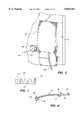
- FIG. 1is an exploded perspective view of a fragmentary portion of a rear wall of a computer housing, with an electric cable of peripheral equipment plugged into the rear wall, and with a gate or cover in the process of being installed onto the rear wall;
- FIG. 2is a view similar to FIG. 1 depicting the gate in its installed condition, and further depicting a locking cable and a cover in the process of being installed;
- FIG. 3is a view similar to FIG. 2 after the cover and locking cable have been installed
- FIG. 4is a rear perspective view of the gate depicted in FIG. 1;
- FIG. 5is a front elevational view of the gate
- FIG. 6is a sectional view taken along the line 6--6 in FIG. 5;
- FIG. 7is a plan view of a comb member depicted in FIG. 1.
- FIG. 1Depicted in FIG. 1 is an external side of a rear panel 10 of a housing 12 of a personal computer 14.
- a recess 16 formed in that external sideincludes a stepped end wall 18 and a pair of side walls 20, 22.
- the end wall 18is stepped to form vertically adjacent portions 18A, 18B, 18C and 18D.
- plug receptacles 24adapted to receive plugs 25 of electric cables 26 of peripheral equipment such as a keyboard, modem, monitor, printer, etc. (only one such cable being depicted).
- the recess 16thus forms an area in which the electric cables are disposed.
- the bottom portion 18D of the end wall 18forms an opening through which the electric cable projects.
- a horizontal slit 32Situated in the portion 18C of the end wall 18 is a horizontal slit 32 (see FIG. 1) which is adapted to receive a slotted element or comb 34 which is connected, e.g., by friction fit, within the slit 32.
- the comb 34which is also shown in FIG. 6, forms a plurality of slots 33 sized to receive the electric cables by friction fit.
- the combis preferably formed of an elastic material such as plastic or rubber.
- a securing member in the form of a cover or gate 46is adapted to be mounted to the fingers 42.
- the gate 46which is depicted in FIGS. 1, 2, 4 and 5, includes opposite ends 48, 50.
- the end 48constitutes a hinge end, and the other end 50 constitutes a locking end.
- the hinge endincludes a pair of recesses 52 (see FIGS. 4 and 6) adapted to receive respective ones of the fingers 42 to define therewith a hinge enabling the gate to be swung between open and closed positions.
- the recesses 52are separated from each other by a flange 55 which is sized to enter a space formed between the fingers 42 in order to guide the gate during its rotation.
- the gate 46In its closed position, the gate extends across a portion of the recess 16 in which the comb 34 is mounted as shown in FIG. 2, the gate thus functioning to cover the comb.
- the gate 46thus forms with the portion 18C of the end wall 18 a gap G that is narrower than the plug 25 of the electric cable 26.
- the gate 46could be configured to lie closely adjacent a front edge 30 of the comb 34 when the gate is in its closed position, to prevent the cable from becoming dislodged from its respective slot 33.
- the locking end 50 of the gateincludes a flexible latch finger 54 which is adapted to enter a recess 56 formed in the panel 10 when the gate 46 is closed.
- the latch finger 54engages behind a shoulder (not shown) disposed in the recess 56 in order to yieldably (e.g. frictionally) retain the gate in a closed position.
- a rib 58 formed on the gateenables a user to grip the gate to swing it open.
- the panel 10includes a projection 60 having an opening 62 formed therein which is adapted to receive an external locking element 63 of a conventional anchoring cable device 64, such as a Kensington security lock for example, in order to fixedly anchor the computer housing 12 to a stationary structure such as a wall.
- the locking element 63includes a key-actuated T-bar (not shown) which enters the opening 62 of the projection 60 and becomes locked to the projection when rotated by ninety degrees with a special key (not shown).
- the locking end 50 of the gateincludes a hole 66 large enough to receive the projection 60 but smaller than the locking element 63 of the anchoring device 64.
- a cover extension element 80can be attached to the gate 46 to overlie the plug receptacles 24 and the upper end of the electric cable and present a neater appearance.
- the cover extension 80can be attached to the gate in any suitable way, such as by a snap fit produced by elastic fingers 82 (see FIG. 2) which grip an upper edge 84 of the gate 46.
- a userconnects the electric cables 26 of peripheral equipment to the computer housing 12 by plugging the plugs 25 into respective receptacles. Intermediate sections of the cables are inserted into respective slots 33 of the comb 34 to present an organized appearance (see FIG. 1).
- the gate 46is installed by inserting the hinge fingers 42 into the respective recesses 52, thereby forming a hinge about which the gate can be swung to its closed position (FIG. 2).
- the locking element 63 of the cable anchoring device 64can be connected to the projection 60 of the housing, to anchor the housing 12 to a support and simultaneously lock the gate 46 to the housing 12. Since the gap G formed between the gate 46 and the wall section 18C is narrower than the plugs 25 of the electric cables, the electric cables cannot be separated from the housing 12.
- the cover extension 80can be snapped onto the gate 46 (FIG. 3) to conceal the upper portions of the cables.
- the gate 46need not be locked to the housing by a housing-anchoring device. Instead, the gate 46 could be locked to the housing by any suitable lock, and the housing could, or could not, be anchored.
- the gate 46need not be mounted by a hinge; any type of mounting, whether swingable or not, could be utilized for the gate.
- the gatecould be employed simply to function as a cover to conceal the comb and as a carrier for the cover extension 80.
Landscapes
- Engineering & Computer Science (AREA)
- Theoretical Computer Science (AREA)
- Computer Hardware Design (AREA)
- Power Engineering (AREA)
- Human Computer Interaction (AREA)
- Physics & Mathematics (AREA)
- General Engineering & Computer Science (AREA)
- General Physics & Mathematics (AREA)
- Casings For Electric Apparatus (AREA)
Abstract
Description
The present invention relates to methods and apparatus for organizing the electric cables of peripheral equipment plugged into a computer housing.
It is conventional to provide a personal computer with peripheral equipment, such as keyboards, modems, monitors, printers, etc., which have electric cables that plug into receptacles provided in the computer housing. Those cables tend to lay haphazardly across the desktop and contribute to clutter, as well as detracting from the overall appearance of the computer.
It would be desirable to organize those cables into a neater arrangement, and to dress out the appearance of the computer housing to which the cables are plugged.
Those and other objects are achieved by the present invention which relates to a personal computer that comprises a housing having an outer wall. The outer wall includes a plurality of plug receptacles adapted to receive the electric plug-in cables of peripheral equipment. Slots are disposed on the outer wall at a location spaced from the receptacles, the slots adapted to receive intermediate portions of the electric cables. A cover is attachable to the outer wall in a position covering at least the slots.
The slots are preferably formed by a comb element which is mounted in a slit formed in the outer wall. The comb element is preferably formed of an elastic material to hold the cable therein by friction. A cover extension could be mounted on the cover to extend across the plug receptacles.
The present invention relates to a method of orienting an electric cable that is plugged into a plug receptacle formed in an outer wall of a personal computer. The method comprises inserting an intermediate portion of the electric cable into one of a plurality of slots formed on the outer wall, and positioning a cover on the outer wall to cover at least the slots.
The objects and advantages of the invention will become apparent from the following detailed description of preferred embodiments thereof in connection with the accompanying drawing in which like numerals designate like elements and in which:
FIG. 1 is an exploded perspective view of a fragmentary portion of a rear wall of a computer housing, with an electric cable of peripheral equipment plugged into the rear wall, and with a gate or cover in the process of being installed onto the rear wall;
FIG. 2 is a view similar to FIG. 1 depicting the gate in its installed condition, and further depicting a locking cable and a cover in the process of being installed;
FIG. 3 is a view similar to FIG. 2 after the cover and locking cable have been installed;
FIG. 4 is a rear perspective view of the gate depicted in FIG. 1;
FIG. 5 is a front elevational view of the gate;
FIG. 6 is a sectional view taken along theline 6--6 in FIG. 5; and
FIG. 7 is a plan view of a comb member depicted in FIG. 1.
Depicted in FIG. 1 is an external side of arear panel 10 of ahousing 12 of apersonal computer 14. Arecess 16 formed in that external side includes astepped end wall 18 and a pair ofside walls end wall 18 is stepped to form verticallyadjacent portions side wall 20 areplug receptacles 24 adapted to receiveplugs 25 ofelectric cables 26 of peripheral equipment such as a keyboard, modem, monitor, printer, etc. (only one such cable being depicted). Therecess 16 thus forms an area in which the electric cables are disposed. Thebottom portion 18D of theend wall 18 forms an opening through which the electric cable projects.
Situated in theportion 18C of theend wall 18 is a horizontal slit 32 (see FIG. 1) which is adapted to receive a slotted element orcomb 34 which is connected, e.g., by friction fit, within theslit 32. Thecomb 34, which is also shown in FIG. 6, forms a plurality ofslots 33 sized to receive the electric cables by friction fit. The comb is preferably formed of an elastic material such as plastic or rubber. By running the cables through the comb, the cables become more organized, and manageable, besides improving the overall appearance of the computer area.
Formed along an edge 40 of one of theside walls 22 of the housing are twofingers 42 which extend in a direction away from theother side wall 20. A securing member in the form of a cover orgate 46 is adapted to be mounted to thefingers 42. Thegate 46, which is depicted in FIGS. 1, 2, 4 and 5, includesopposite ends end 48 constitutes a hinge end, and theother end 50 constitutes a locking end. The hinge end includes a pair of recesses 52 (see FIGS. 4 and 6) adapted to receive respective ones of thefingers 42 to define therewith a hinge enabling the gate to be swung between open and closed positions. Therecesses 52 are separated from each other by a flange 55 which is sized to enter a space formed between thefingers 42 in order to guide the gate during its rotation.
In its closed position, the gate extends across a portion of therecess 16 in which thecomb 34 is mounted as shown in FIG. 2, the gate thus functioning to cover the comb. Thegate 46 thus forms with theportion 18C of the end wall 18 a gap G that is narrower than theplug 25 of theelectric cable 26. Thus, with thecable 26 situated between thegate 46 andend wall 18, thecable 26 cannot be separated from thehousing 12. If desired, thegate 46 could be configured to lie closely adjacent afront edge 30 of thecomb 34 when the gate is in its closed position, to prevent the cable from becoming dislodged from itsrespective slot 33.
Thelocking end 50 of the gate includes aflexible latch finger 54 which is adapted to enter arecess 56 formed in thepanel 10 when thegate 46 is closed. Thelatch finger 54 engages behind a shoulder (not shown) disposed in therecess 56 in order to yieldably (e.g. frictionally) retain the gate in a closed position. Arib 58 formed on the gate enables a user to grip the gate to swing it open.
Thepanel 10 includes aprojection 60 having anopening 62 formed therein which is adapted to receive anexternal locking element 63 of a conventionalanchoring cable device 64, such as a Kensington security lock for example, in order to fixedly anchor thecomputer housing 12 to a stationary structure such as a wall. Basically, thelocking element 63 includes a key-actuated T-bar (not shown) which enters theopening 62 of theprojection 60 and becomes locked to the projection when rotated by ninety degrees with a special key (not shown).
Thelocking end 50 of the gate includes ahole 66 large enough to receive theprojection 60 but smaller than thelocking element 63 of theanchoring device 64. Thus, by locking thelocking element 63 to thehousing 12 while thegate 46 is closed, thehousing 12 is anchored to a support, and simultaneously the gate is locked to the housing.
In that way, not only is the housing secured against theft, but the peripheral equipment is locked to thehousing 12 by the closedgate 46. Separation of the peripheral equipment from the housing cannot be accomplished without cutting the respective electric cable, thus deterring such theft.
If desired, acover extension element 80 can be attached to thegate 46 to overlie theplug receptacles 24 and the upper end of the electric cable and present a neater appearance. Thecover extension 80 can be attached to the gate in any suitable way, such as by a snap fit produced by elastic fingers 82 (see FIG. 2) which grip anupper edge 84 of thegate 46.
To utilize the present invention, a user connects theelectric cables 26 of peripheral equipment to thecomputer housing 12 by plugging theplugs 25 into respective receptacles. Intermediate sections of the cables are inserted intorespective slots 33 of thecomb 34 to present an organized appearance (see FIG. 1).
Then thegate 46 is installed by inserting thehinge fingers 42 into therespective recesses 52, thereby forming a hinge about which the gate can be swung to its closed position (FIG. 2). In the closed position of the gate, thelocking element 63 of thecable anchoring device 64 can be connected to theprojection 60 of the housing, to anchor thehousing 12 to a support and simultaneously lock thegate 46 to thehousing 12. Since the gap G formed between thegate 46 and thewall section 18C is narrower than theplugs 25 of the electric cables, the electric cables cannot be separated from thehousing 12.
If a yet neater appearance is desired, thecover extension 80 can be snapped onto the gate 46 (FIG. 3) to conceal the upper portions of the cables.
It will be appreciated that thegate 46 need not be locked to the housing by a housing-anchoring device. Instead, thegate 46 could be locked to the housing by any suitable lock, and the housing could, or could not, be anchored. Thegate 46 need not be mounted by a hinge; any type of mounting, whether swingable or not, could be utilized for the gate.
If the gate-locking feature were not desired, the gate could be employed simply to function as a cover to conceal the comb and as a carrier for thecover extension 80.
Although the present invention has been described in connection with preferred embodiments thereof, it will be appreciated by those skilled in the art that additions, deletions, modifications, and substitutions not specifically described may be made without departing from the spirit and scope of the invention as defined in the appended claims.
Claims (9)
1. A personal computer comprising:
a housing including an outer wall having a plurality of plug receptacles adapted to receive electric plug-in cables of peripheral equipment;
a plurality of slots disposed on the outer wall at a location spaced from the receptacles, the slots adapted to receive intermediate portions of respective electric cables; and
a cover attachable to the outer wall in a position covering at least the slots;
wherein the slots include open ends arranged in a row, the cover extending across the row of open ends when in a closed position and being oriented to retain the cables in the slots.
2. The personal computer according to claim 1 including a comb element mounted to the outer wall, the comb element forming the slots.
3. The personal computer according to claim 2, wherein the outer wall has a slit formed therein, the comb element mounted in the slit.
4. The personal computer according to claim 3, wherein the comb element is formed of an elastic material and is adapted to hold the cables by friction.
5. The personal computer according to claim 1, wherein the cover is swingably mounted on the outer wall.
6. A method of orienting an electric cable that is plugged into a plug receptacle formed in an outer wall of a personal computer, comprising the steps of:
A) inserting an intermediate portion of the electric cable into one of a plurality of slots formed on the outer wall;
B) positioning a cover on the outer wall to cover at least the slots and to retain the electric cable within the slot: and
(C) attaching a cover extension to the cover for covering the plug receptacle.
7. A personal computer comprising:
a housing including an outer wall having a plurality of plug receptacles adapted to receive electric plug-in cables of peripheral equipment;
a plurality of slots disposed on the outer wall at a location spaced from the receptacles, the slots adapted to receive intermediate portions of respective electric cables;
a cover attachable to the outer wall in a position covering at least the slots; and
a cover extension adapted to be removably mounted on the cover for covering the plug receptacles.
8. A personal computer comprising:
a housing including an outer wall having a plurality of plug receptacles adapted to receive electric plug-in cables of peripheral equipment;
a plurality of slots disposed on the outer wall at a location spaced from the receptacles, the slots adapted to receive intermediate portions of respective electric cables; and
a cover attachable to the outer wall in a position covering at least the slots;
wherein the cover is oriented to retain the cables in the slots when the cover is in its closed position.
9. A personal computer comprising:
a housing including an outer wall having a plurality of plug receptacles adapted to receive electric plug-in cables of peripheral equipment;
a plurality of slots disposed on the outer wall at a location spaced from the receptacles, the slots adapted to receive intermediate portions of respective electric cables;
a cover attachable to the outer wall in a position covering at least the slots;
wherein the slots include open ends arranged in a row, the cover extending across the row of open ends; and
a cover extension adapted to be removably mounted on the cover for covering the plug receptacles.
Priority Applications (1)
| Application Number | Priority Date | Filing Date | Title |
|---|---|---|---|
| US08/779,742US5810461A (en) | 1997-01-07 | 1997-01-07 | Methods and apparatus for organizing the electric cables of peripheral equipment attached to a computer housing |
Applications Claiming Priority (1)
| Application Number | Priority Date | Filing Date | Title |
|---|---|---|---|
| US08/779,742US5810461A (en) | 1997-01-07 | 1997-01-07 | Methods and apparatus for organizing the electric cables of peripheral equipment attached to a computer housing |
Publications (1)
| Publication Number | Publication Date |
|---|---|
| US5810461Atrue US5810461A (en) | 1998-09-22 |
Family
ID=25117395
Family Applications (1)
| Application Number | Title | Priority Date | Filing Date |
|---|---|---|---|
| US08/779,742Expired - LifetimeUS5810461A (en) | 1997-01-07 | 1997-01-07 | Methods and apparatus for organizing the electric cables of peripheral equipment attached to a computer housing |
Country Status (1)
| Country | Link |
|---|---|
| US (1) | US5810461A (en) |
Cited By (43)
| Publication number | Priority date | Publication date | Assignee | Title |
|---|---|---|---|---|
| US6122019A (en)* | 1996-08-23 | 2000-09-19 | Samsung Electronics Co., Ltd. | Display device |
| US6266240B1 (en) | 1999-02-04 | 2001-07-24 | Palm, Inc. | Encasement for a handheld computer |
| FR2805357A1 (en)* | 2000-02-22 | 2001-08-24 | Philippe Jean Jack Gressier | Casing for microcomputer includes peripheral connections on top edge, and pivoting flaps retaining cables |
| US6341510B1 (en)* | 1998-01-15 | 2002-01-29 | Top-Cousins Oy | Locking device for computer |
| US6356442B1 (en) | 1999-02-04 | 2002-03-12 | Palm, Inc | Electronically-enabled encasement for a handheld computer |
| US6356443B2 (en) | 1999-11-30 | 2002-03-12 | Palm, Inc. | Handheld computer configured for attachment with an external device |
| US6388877B1 (en) | 1999-02-04 | 2002-05-14 | Palm, Inc. | Handheld computer with open accessory slot |
| US6388870B1 (en) | 1999-02-04 | 2002-05-14 | Palm, Inc. | Housing for a handheld computer |
| US6532148B2 (en) | 1999-11-30 | 2003-03-11 | Palm, Inc. | Mechanism for attaching accessory devices to handheld computers |
| US6535199B1 (en) | 1999-02-04 | 2003-03-18 | Palm, Inc. | Smart cover for a handheld computer |
| US6788285B2 (en) | 2001-04-10 | 2004-09-07 | Palmone, Inc. | Portable computer with removable input mechanism |
| US6865076B2 (en) | 1999-02-04 | 2005-03-08 | Palmone, Inc. | Electronically-enabled housing apparatus for a computing device |
| US20050200765A1 (en)* | 2004-03-15 | 2005-09-15 | Steve Sanchez | Flat panel TV screen frame system |
| US20070114339A1 (en)* | 2005-11-22 | 2007-05-24 | Winchester Mary A | Flexible conduit storage organizer |
| US7275836B2 (en) | 2005-08-13 | 2007-10-02 | Palm, Inc. | Lighting and usability features for key structures and keypads on computing devices |
| US7294802B2 (en) | 2005-08-13 | 2007-11-13 | Palm, Inc. | Lighting and usability features for key structures and keypads on computing devices |
| US20070280619A1 (en)* | 2006-05-23 | 2007-12-06 | Conner Mark E | Multi-directional optical splice organizer |
| US20090059495A1 (en)* | 2007-08-30 | 2009-03-05 | Yoshimichi Matsuoka | Housing construction for mobile computing device |
| US7511700B2 (en) | 2005-03-14 | 2009-03-31 | Palm, Inc. | Device and technique for assigning different inputs to keys on a keypad |
| US7525534B2 (en) | 2005-03-14 | 2009-04-28 | Palm, Inc. | Small form-factor keypad for mobile computing devices |
| US7525053B2 (en) | 2006-09-08 | 2009-04-28 | Palm, Inc. | Enhanced key structure with combined keycap for a mobile computing device |
| US7623118B2 (en) | 2005-03-14 | 2009-11-24 | Palm, Inc. | Actuation mechanism for use with keyboards on mobile computing devices |
| USD613743S1 (en) | 2007-08-30 | 2010-04-13 | Palm, Inc. | Mobile computing device |
| US20100269552A1 (en)* | 2009-04-23 | 2010-10-28 | Dell Products L.P. | Compact Security Device For Systems And Peripherals |
| EP2130107A4 (en)* | 2007-03-27 | 2012-12-19 | Hewlett Packard Development Co | Cable management system |
| US8350728B2 (en) | 2010-04-23 | 2013-01-08 | Hewlett-Packard Development Company, L.P. | Keyboard with integrated and numeric keypad |
| US8467651B2 (en) | 2009-09-30 | 2013-06-18 | Ccs Technology Inc. | Fiber optic terminals configured to dispose a fiber optic connection panel(s) within an optical fiber perimeter and related methods |
| US8520996B2 (en) | 2009-03-31 | 2013-08-27 | Corning Cable Systems Llc | Removably mountable fiber optic terminal |
| US8792767B2 (en) | 2010-04-16 | 2014-07-29 | Ccs Technology, Inc. | Distribution device |
| US8798427B2 (en) | 2007-09-05 | 2014-08-05 | Corning Cable Systems Llc | Fiber optic terminal assembly |
| US8879882B2 (en) | 2008-10-27 | 2014-11-04 | Corning Cable Systems Llc | Variably configurable and modular local convergence point |
| US8909019B2 (en) | 2012-10-11 | 2014-12-09 | Ccs Technology, Inc. | System comprising a plurality of distribution devices and distribution device |
| US8989822B2 (en) | 2006-09-08 | 2015-03-24 | Qualcomm Incorporated | Keypad assembly for use on a contoured surface of a mobile computing device |
| US9004778B2 (en) | 2012-06-29 | 2015-04-14 | Corning Cable Systems Llc | Indexable optical fiber connectors and optical fiber connector arrays |
| US9049500B2 (en) | 2012-08-31 | 2015-06-02 | Corning Cable Systems Llc | Fiber optic terminals, systems, and methods for network service management |
| US9142369B2 (en) | 2005-03-14 | 2015-09-22 | Qualcomm Incorporated | Stack assembly for implementing keypads on mobile computing devices |
| US9185833B2 (en)* | 2014-03-12 | 2015-11-10 | Lenovo Enterprise Solutions (Singapore) Pte. Ltd. | Electronic device housing |
| US9219546B2 (en) | 2011-12-12 | 2015-12-22 | Corning Optical Communications LLC | Extremely high frequency (EHF) distributed antenna systems, and related components and methods |
| US9323020B2 (en) | 2008-10-09 | 2016-04-26 | Corning Cable Systems (Shanghai) Co. Ltd | Fiber optic terminal having adapter panel supporting both input and output fibers from an optical splitter |
| US9547144B2 (en) | 2010-03-16 | 2017-01-17 | Corning Optical Communications LLC | Fiber optic distribution network for multiple dwelling units |
| US9547145B2 (en) | 2010-10-19 | 2017-01-17 | Corning Optical Communications LLC | Local convergence point for multiple dwelling unit fiber optic distribution network |
| US10095279B2 (en)* | 2016-02-12 | 2018-10-09 | Fujitsu Technology Solutions Intellectual Property Gmbh | Assembly for a computer system and cable covering unit for an assembly |
| US10110307B2 (en) | 2012-03-02 | 2018-10-23 | Corning Optical Communications LLC | Optical network units (ONUs) for high bandwidth connectivity, and related components and methods |
Citations (12)
| Publication number | Priority date | Publication date | Assignee | Title |
|---|---|---|---|---|
| US2531110A (en)* | 1947-04-03 | 1950-11-21 | Gen Electric | Wiring duct |
| US3278066A (en)* | 1965-05-12 | 1966-10-11 | Square D Co | Closure plate for electrical panelboard |
| US3341268A (en)* | 1965-08-06 | 1967-09-12 | James L Hall Co Inc | Utility cabinet |
| US3523156A (en)* | 1968-09-18 | 1970-08-04 | Lawrence Phillips Jr | Electrical service center having an improved moisture barrier |
| US4748540A (en)* | 1987-04-24 | 1988-05-31 | Honeywell Bull Inc. | Compact packaging of electronic equipment within a small profile enclosure |
| US4898009A (en)* | 1989-03-22 | 1990-02-06 | Lama Systems Inc. | Protective cover for a personal computer |
| US4985695A (en)* | 1989-08-09 | 1991-01-15 | Wilkinson William T | Computer security device |
| US5018052A (en)* | 1990-01-08 | 1991-05-21 | Sun Microsystems, Inc. | Cable management apparatus for a computer workstation housing |
| US5142442A (en)* | 1990-11-13 | 1992-08-25 | Compaq Computer Corporation | Combined fan spacer and wire guide |
| US5228319A (en)* | 1991-09-25 | 1993-07-20 | Dell Usa, L.P. | Desktop computer locking assembly |
| US5233881A (en)* | 1992-07-17 | 1993-08-10 | General Motors Corporation | Door latch rod clip and insulator |
| US5568362A (en)* | 1992-09-25 | 1996-10-22 | Atlas Copco Tools Ab | Cabinet for housing electronic equipment connectable to machines or power tools for performing operations |
- 1997
- 1997-01-07USUS08/779,742patent/US5810461A/ennot_activeExpired - Lifetime
Patent Citations (12)
| Publication number | Priority date | Publication date | Assignee | Title |
|---|---|---|---|---|
| US2531110A (en)* | 1947-04-03 | 1950-11-21 | Gen Electric | Wiring duct |
| US3278066A (en)* | 1965-05-12 | 1966-10-11 | Square D Co | Closure plate for electrical panelboard |
| US3341268A (en)* | 1965-08-06 | 1967-09-12 | James L Hall Co Inc | Utility cabinet |
| US3523156A (en)* | 1968-09-18 | 1970-08-04 | Lawrence Phillips Jr | Electrical service center having an improved moisture barrier |
| US4748540A (en)* | 1987-04-24 | 1988-05-31 | Honeywell Bull Inc. | Compact packaging of electronic equipment within a small profile enclosure |
| US4898009A (en)* | 1989-03-22 | 1990-02-06 | Lama Systems Inc. | Protective cover for a personal computer |
| US4985695A (en)* | 1989-08-09 | 1991-01-15 | Wilkinson William T | Computer security device |
| US5018052A (en)* | 1990-01-08 | 1991-05-21 | Sun Microsystems, Inc. | Cable management apparatus for a computer workstation housing |
| US5142442A (en)* | 1990-11-13 | 1992-08-25 | Compaq Computer Corporation | Combined fan spacer and wire guide |
| US5228319A (en)* | 1991-09-25 | 1993-07-20 | Dell Usa, L.P. | Desktop computer locking assembly |
| US5233881A (en)* | 1992-07-17 | 1993-08-10 | General Motors Corporation | Door latch rod clip and insulator |
| US5568362A (en)* | 1992-09-25 | 1996-10-22 | Atlas Copco Tools Ab | Cabinet for housing electronic equipment connectable to machines or power tools for performing operations |
Cited By (58)
| Publication number | Priority date | Publication date | Assignee | Title |
|---|---|---|---|---|
| US6122019A (en)* | 1996-08-23 | 2000-09-19 | Samsung Electronics Co., Ltd. | Display device |
| US6341510B1 (en)* | 1998-01-15 | 2002-01-29 | Top-Cousins Oy | Locking device for computer |
| US6388877B1 (en) | 1999-02-04 | 2002-05-14 | Palm, Inc. | Handheld computer with open accessory slot |
| US6356442B1 (en) | 1999-02-04 | 2002-03-12 | Palm, Inc | Electronically-enabled encasement for a handheld computer |
| US9367083B2 (en) | 1999-02-04 | 2016-06-14 | Hewlett-Packard Development Company, L.P. | Computing device housing |
| US6388870B1 (en) | 1999-02-04 | 2002-05-14 | Palm, Inc. | Housing for a handheld computer |
| US6535199B1 (en) | 1999-02-04 | 2003-03-18 | Palm, Inc. | Smart cover for a handheld computer |
| US6865076B2 (en) | 1999-02-04 | 2005-03-08 | Palmone, Inc. | Electronically-enabled housing apparatus for a computing device |
| US6266240B1 (en) | 1999-02-04 | 2001-07-24 | Palm, Inc. | Encasement for a handheld computer |
| US8804332B2 (en) | 1999-02-04 | 2014-08-12 | Hewlett-Packard Development Company, L.P. | Handheld computer |
| US7061762B2 (en) | 1999-02-04 | 2006-06-13 | Palm, Inc. | Housing for a computing apparatus |
| US6356443B2 (en) | 1999-11-30 | 2002-03-12 | Palm, Inc. | Handheld computer configured for attachment with an external device |
| US6532148B2 (en) | 1999-11-30 | 2003-03-11 | Palm, Inc. | Mechanism for attaching accessory devices to handheld computers |
| FR2805357A1 (en)* | 2000-02-22 | 2001-08-24 | Philippe Jean Jack Gressier | Casing for microcomputer includes peripheral connections on top edge, and pivoting flaps retaining cables |
| US6788285B2 (en) | 2001-04-10 | 2004-09-07 | Palmone, Inc. | Portable computer with removable input mechanism |
| US20050200765A1 (en)* | 2004-03-15 | 2005-09-15 | Steve Sanchez | Flat panel TV screen frame system |
| WO2005089323A3 (en)* | 2004-03-15 | 2006-02-16 | Steve Sanchez | Flat panel tv screen frame system |
| US7808563B2 (en)* | 2004-03-15 | 2010-10-05 | Steve Sanchez | Flat panel TV screen frame system |
| US9142369B2 (en) | 2005-03-14 | 2015-09-22 | Qualcomm Incorporated | Stack assembly for implementing keypads on mobile computing devices |
| US8373663B2 (en) | 2005-03-14 | 2013-02-12 | Hewlett-Packard Development Company, L.P. | Small form-factor keypad for mobile computing devices |
| US7511700B2 (en) | 2005-03-14 | 2009-03-31 | Palm, Inc. | Device and technique for assigning different inputs to keys on a keypad |
| US7525534B2 (en) | 2005-03-14 | 2009-04-28 | Palm, Inc. | Small form-factor keypad for mobile computing devices |
| US7623118B2 (en) | 2005-03-14 | 2009-11-24 | Palm, Inc. | Actuation mechanism for use with keyboards on mobile computing devices |
| US7275836B2 (en) | 2005-08-13 | 2007-10-02 | Palm, Inc. | Lighting and usability features for key structures and keypads on computing devices |
| US7294802B2 (en) | 2005-08-13 | 2007-11-13 | Palm, Inc. | Lighting and usability features for key structures and keypads on computing devices |
| US7708416B2 (en) | 2005-08-13 | 2010-05-04 | Michael Yurochko | Lighting and usability features for key structures and keypads on computing devices |
| US7712709B2 (en) | 2005-11-22 | 2010-05-11 | Mary Annette Winchester | Flexible conduit storage organizer |
| US20070114339A1 (en)* | 2005-11-22 | 2007-05-24 | Winchester Mary A | Flexible conduit storage organizer |
| US20070235597A1 (en)* | 2005-11-22 | 2007-10-11 | Winchester Mary A | Flexible conduit storage organizer |
| US20070280619A1 (en)* | 2006-05-23 | 2007-12-06 | Conner Mark E | Multi-directional optical splice organizer |
| US7525053B2 (en) | 2006-09-08 | 2009-04-28 | Palm, Inc. | Enhanced key structure with combined keycap for a mobile computing device |
| US8989822B2 (en) | 2006-09-08 | 2015-03-24 | Qualcomm Incorporated | Keypad assembly for use on a contoured surface of a mobile computing device |
| EP2130107A4 (en)* | 2007-03-27 | 2012-12-19 | Hewlett Packard Development Co | Cable management system |
| USD613743S1 (en) | 2007-08-30 | 2010-04-13 | Palm, Inc. | Mobile computing device |
| US8270158B2 (en) | 2007-08-30 | 2012-09-18 | Hewlett-Packard Development Company, L.P. | Housing construction for mobile computing device |
| US20090059495A1 (en)* | 2007-08-30 | 2009-03-05 | Yoshimichi Matsuoka | Housing construction for mobile computing device |
| US8798427B2 (en) | 2007-09-05 | 2014-08-05 | Corning Cable Systems Llc | Fiber optic terminal assembly |
| US9323020B2 (en) | 2008-10-09 | 2016-04-26 | Corning Cable Systems (Shanghai) Co. Ltd | Fiber optic terminal having adapter panel supporting both input and output fibers from an optical splitter |
| US8879882B2 (en) | 2008-10-27 | 2014-11-04 | Corning Cable Systems Llc | Variably configurable and modular local convergence point |
| US8520996B2 (en) | 2009-03-31 | 2013-08-27 | Corning Cable Systems Llc | Removably mountable fiber optic terminal |
| US8042365B2 (en)* | 2009-04-23 | 2011-10-25 | Dell Products L.P. | Compact security device for systems and peripherals |
| US20100269552A1 (en)* | 2009-04-23 | 2010-10-28 | Dell Products L.P. | Compact Security Device For Systems And Peripherals |
| US8467651B2 (en) | 2009-09-30 | 2013-06-18 | Ccs Technology Inc. | Fiber optic terminals configured to dispose a fiber optic connection panel(s) within an optical fiber perimeter and related methods |
| US9547144B2 (en) | 2010-03-16 | 2017-01-17 | Corning Optical Communications LLC | Fiber optic distribution network for multiple dwelling units |
| US8792767B2 (en) | 2010-04-16 | 2014-07-29 | Ccs Technology, Inc. | Distribution device |
| US8350728B2 (en) | 2010-04-23 | 2013-01-08 | Hewlett-Packard Development Company, L.P. | Keyboard with integrated and numeric keypad |
| US9720197B2 (en) | 2010-10-19 | 2017-08-01 | Corning Optical Communications LLC | Transition box for multiple dwelling unit fiber optic distribution network |
| US9547145B2 (en) | 2010-10-19 | 2017-01-17 | Corning Optical Communications LLC | Local convergence point for multiple dwelling unit fiber optic distribution network |
| US9219546B2 (en) | 2011-12-12 | 2015-12-22 | Corning Optical Communications LLC | Extremely high frequency (EHF) distributed antenna systems, and related components and methods |
| US9602209B2 (en) | 2011-12-12 | 2017-03-21 | Corning Optical Communications LLC | Extremely high frequency (EHF) distributed antenna systems, and related components and methods |
| US9800339B2 (en) | 2011-12-12 | 2017-10-24 | Corning Optical Communications LLC | Extremely high frequency (EHF) distributed antenna systems, and related components and methods |
| US10110305B2 (en) | 2011-12-12 | 2018-10-23 | Corning Optical Communications LLC | Extremely high frequency (EHF) distributed antenna systems, and related components and methods |
| US10110307B2 (en) | 2012-03-02 | 2018-10-23 | Corning Optical Communications LLC | Optical network units (ONUs) for high bandwidth connectivity, and related components and methods |
| US9004778B2 (en) | 2012-06-29 | 2015-04-14 | Corning Cable Systems Llc | Indexable optical fiber connectors and optical fiber connector arrays |
| US9049500B2 (en) | 2012-08-31 | 2015-06-02 | Corning Cable Systems Llc | Fiber optic terminals, systems, and methods for network service management |
| US8909019B2 (en) | 2012-10-11 | 2014-12-09 | Ccs Technology, Inc. | System comprising a plurality of distribution devices and distribution device |
| US9185833B2 (en)* | 2014-03-12 | 2015-11-10 | Lenovo Enterprise Solutions (Singapore) Pte. Ltd. | Electronic device housing |
| US10095279B2 (en)* | 2016-02-12 | 2018-10-09 | Fujitsu Technology Solutions Intellectual Property Gmbh | Assembly for a computer system and cable covering unit for an assembly |
Similar Documents
| Publication | Publication Date | Title |
|---|---|---|
| US5810461A (en) | Methods and apparatus for organizing the electric cables of peripheral equipment attached to a computer housing | |
| US5816081A (en) | Methods and apparatus for locking peripheral equipment to a computer housing | |
| US4593541A (en) | Locking electrical outlet box | |
| US5676566A (en) | Multimedia outlet | |
| CA1206578A (en) | Cable manager | |
| US4381063A (en) | Weatherproof cover assembly for electrical wiring devices | |
| US5257946A (en) | Recessed electric outlet assembly with cover plate | |
| US5605466A (en) | Wall outlet adapter having sawtooth profile | |
| US6133531A (en) | Weatherproof outlet cover | |
| CA2175425C (en) | Closure cap with gasket for electrical connector housing | |
| US6059156A (en) | Attachment system for a portable device | |
| US5851692A (en) | Electronic device having a concealed battery latch door | |
| US5447045A (en) | Apparatus for locking a closed notebook computer on a computer support | |
| US5362924A (en) | Protective cover for electrical wall sockets | |
| US5174773A (en) | Child-proof plug cover | |
| US4705335A (en) | Plug safe | |
| US5231562A (en) | Desk top wire management apparatus | |
| US5361610A (en) | Totelock | |
| US8013245B2 (en) | Weatherproof cover assembly for an electrical box having a water intrusion barrier | |
| US7410372B2 (en) | Weatherproof cover assembly | |
| US6916989B2 (en) | Protective electrical outlet device | |
| US5447044A (en) | Apparatus for locking a notebook computer on a computer support | |
| GB2348459A (en) | Lid restraint for portable computer | |
| US7121853B1 (en) | Locking device for electrical plugs and electrical outlets | |
| US5340324A (en) | Phone jack lock |
Legal Events
| Date | Code | Title | Description |
|---|---|---|---|
| AS | Assignment | Owner name:APPLE COMPUTER INC., CALIFORNIA Free format text:ASSIGNMENT OF ASSIGNORS INTEREST;ASSIGNORS:IVE, JONATHAN;MOLLER, RONALD J.;REEL/FRAME:008484/0614;SIGNING DATES FROM 19970414 TO 19970417 | |
| FEPP | Fee payment procedure | Free format text:PAYOR NUMBER ASSIGNED (ORIGINAL EVENT CODE: ASPN); ENTITY STATUS OF PATENT OWNER: LARGE ENTITY | |
| STCF | Information on status: patent grant | Free format text:PATENTED CASE | |
| FPAY | Fee payment | Year of fee payment:4 | |
| FPAY | Fee payment | Year of fee payment:8 | |
| AS | Assignment | Owner name:APPLE INC.,CALIFORNIA Free format text:CHANGE OF NAME;ASSIGNOR:APPLE COMPUTER, INC.;REEL/FRAME:019235/0583 Effective date:20070109 Owner name:APPLE INC., CALIFORNIA Free format text:CHANGE OF NAME;ASSIGNOR:APPLE COMPUTER, INC.;REEL/FRAME:019235/0583 Effective date:20070109 | |
| FPAY | Fee payment | Year of fee payment:12 |