US5809111A - Telephone control module and user site network and methods of operation - Google Patents
Telephone control module and user site network and methods of operationDownload PDFInfo
- Publication number
- US5809111A US5809111AUS08/626,724US62672496AUS5809111AUS 5809111 AUS5809111 AUS 5809111AUS 62672496 AUS62672496 AUS 62672496AUS 5809111 AUS5809111 AUS 5809111A
- Authority
- US
- United States
- Prior art keywords
- telephone
- site
- telephone line
- operable
- network
- Prior art date
- Legal status (The legal status is an assumption and is not a legal conclusion. Google has not performed a legal analysis and makes no representation as to the accuracy of the status listed.)
- Expired - Fee Related
Links
- 238000000034methodMethods0.000titleclaimsdescription28
- 238000004891communicationMethods0.000claimsabstractdescription92
- 238000012545processingMethods0.000claimsdescription39
- 230000000593degrading effectEffects0.000claimsdescription6
- 238000012544monitoring processMethods0.000claimsdescription5
- 230000002093peripheral effectEffects0.000claimsdescription4
- 230000008878couplingEffects0.000claims4
- 238000010168coupling processMethods0.000claims4
- 238000005859coupling reactionMethods0.000claims4
- 230000008901benefitEffects0.000description13
- 230000008569processEffects0.000description11
- 238000010586diagramMethods0.000description10
- 230000005540biological transmissionEffects0.000description6
- 238000001514detection methodMethods0.000description6
- 238000002955isolationMethods0.000description4
- 210000002569neuronAnatomy0.000description4
- 230000004044responseEffects0.000description3
- 238000012360testing methodMethods0.000description3
- RYGMFSIKBFXOCR-UHFFFAOYSA-NCopperChemical compound[Cu]RYGMFSIKBFXOCR-UHFFFAOYSA-N0.000description2
- 239000013307optical fiberSubstances0.000description2
- 238000012546transferMethods0.000description2
- 230000004075alterationEffects0.000description1
- 230000001413cellular effectEffects0.000description1
- 238000004883computer applicationMethods0.000description1
- 230000003993interactionEffects0.000description1
- 238000006467substitution reactionMethods0.000description1
Images


Classifications
- H—ELECTRICITY
- H04—ELECTRIC COMMUNICATION TECHNIQUE
- H04M—TELEPHONIC COMMUNICATION
- H04M9/00—Arrangements for interconnection not involving centralised switching
- H04M9/02—Arrangements for interconnection not involving centralised switching involving a common line for all parties
- H—ELECTRICITY
- H04—ELECTRIC COMMUNICATION TECHNIQUE
- H04M—TELEPHONIC COMMUNICATION
- H04M1/00—Substation equipment, e.g. for use by subscribers
- H04M1/71—Substation extension arrangements
- H04M1/715—Substation extension arrangements using two or more extensions per line
Definitions
- This inventionrelates in general to the field of electronic systems, and more particularly to a telephone control module and a user site network and methods of operation.
- a multi-station systemcan include one or more telephone lines connected to two or more electronic devices.
- a termination point located at the user sitecan be connected with a central office in a telephone network to provide the user site with one or more telephone lines.
- the termination pointcan be what is commonly called a "terminal strip.”
- site telephone linescan emanate from the terminal strip and connect to telephone outlets.
- the telephone outletscan provide access to the telephone line or lines provided by the telephone network.
- Individual telephones and key-sets as well as other electronic devicese.g., facsimile machines, answering machines, modems, personal computers and peripherals, etc.
- the topology of a multi-station telephone systemis often a star configuration, although other topologies are possible.
- telephone line communications between the various electronic devices of the multi-station telephone system and the telephone networkcan be ISDN (Integrated Service Digital Network) or POTS (Plain Old Telephone System) type communications.
- Telephone line communicationsmay also be provided by other types of communications such as radio frequency or satellite based communications and, in the near future, cable systems.
- the site telephone lines that support telephone line communicationsinclude a number of pairs of wires.
- one pair of wiresare used for standard telephone operation and are referred to as the tip and ring wires.
- Other types of communicationsuse other configurations for the site telephone lines.
- PBXPrimary Branch Exchange
- PBX systemscan provide call processing features such as automatic call answering, call forwarding, call transfer, conferencing, and voice mail as well as supporting intra-site telephone communication.
- PBX systemsprovide such features as part of an overall function to provide an interface between a larger number of individual telephone sets and a smaller number of trunk lines of the telephone network.
- Other user sitesutilize conventional computer based systems to provide analogous call processing features.
- PBX and computer based systemsare too expensive and complex for many user sites, such as personal residences or small businesses, that have one or more telephone lines connected to multiple telephones, key-sets or other electronic devices.
- a telephone control module and user site network and methods of operationare provided that substantially eliminate or reduce disadvantages and problems associated with prior multi-station telephone systems.
- a telephone control modulefor use in a multi-station telephone system.
- the telephone control moduleincludes a telephone line interface operable to couple to and interface with a site telephone line located in a user site where the site telephone line is coupled to a telephone line provided by a telephone network.
- the telephone control modulealso includes an electronic device interface operable to couple to and interface with an electronic device located at the user site.
- the telephone control modulefurther includes a logic/control unit coupled to the telephone line interface and to the electronic device interface.
- the logic/control unitis operable to monitor telephone line communications on the site telephone line and to monitor the electronic device.
- the logic/control unitis also operable to isolate the electronic device from and couple the electronic device to the site telephone line.
- the logic/control unitis further operable to communicate with other telephone control modules to form a user site network for providing control of telephone line communications.
- a multi-station telephone systemhaving a telephone control module based user site network.
- the systemincludes a plurality of electronic devices located at a user site.
- the systemalso includes a site telephone line coupled to a telephone line provided by a telephone network and extending through the user site.
- a plurality of telephone control modulesare coupled to the site telephone line and to associated electronic devices.
- the telephone control modulesare operable to monitor telephone line communications on the site telephone line and to monitor the associated electronic devices.
- the telephone control modulesare also operable to isolate associated electronic devices from and to couple associated electronic devices to the site telephone line.
- Each telephone control moduleis further operable to communicate with other telephone control modules to form a user site network for providing control of telephone line communications.
- a user site network supported by a site telephone lineis provided.
- a plurality of electronic devicesare located at a user site, and a site telephone line extends through the user site.
- a plurality of telephone control modulesare coupled to the site telephone line and to associated electronic devices.
- the telephone control modulesare operable to monitor a state of associated electronic devices and to couple associated electronic devices to and isolate associated electronic devices from the site telephone line.
- Each telephone control moduleis further operable to communicate with other telephone control modules using the site telephone line to form a user site network between the plurality of electronic devices.
- a technical advantage of the present inventionis the transmission and reception of information between telephone control modules without limiting normal operation of the telephone line provided by the telephone network or the operation of the electronic devices coupled to the telephone control modules.
- An ability to uniquely identify telephone control modules such that they can be addressed separatelyis another technical advantage of the present invention.
- the use of telephone control modules to provide intrasite communication between telephones or key-sets of a multi-station telephone systemis a further technical advantage of the present invention.
- FIG. 1is a block diagram of one embodiment of a multi-station telephone system having a telephone control module based user site network constructed according to the teachings of the present invention
- FIG. 2is a block diagram of one embodiment of a telephone control module constructed according to the teachings of the present invention
- FIG. 3is a block diagram of one implementation of a user site network having a master/slave topology according to the teachings of the present invention
- FIG. 4is a block diagram of one embodiment of a telephone control module for use with a standard telephone according to the teachings of the present invention
- FIG. 5is a block diagram of one embodiment of telephone control modules in a master/slave topology for use with a standard telephone according to the teachings of the present invention.
- FIG. 6is a flow chart of one embodiment of a process for providing call processing features to a multi-station telephone system according to the teachings of the present invention.
- FIG. 1is a block diagram of one embodiment of a multi-station telephone system having a telephone control module based user site network constructed according to the teachings of the present invention.
- a telephone network 10can be coupled to a user site 12 and can include a central office 14.
- Telephone network 10can be a local telephone network, cellular network, cable system based telephone network or other network providing telecommunications interconnectivity.
- Telephone network 10can be coupled to user site 12 through a telephone line 16.
- Telephone line 16supports telephone line communications 18 between telephone network 10 and user site 12.
- Telephone line 16can comprise a combination of copper wire, optical fiber, radio frequency transmissions, or other medium upon or through which telephone line communications 18 can be supported.
- Telephone line communications 18can be based upon an ISDN, POTS or other telephone line communication protocol.
- User site 12can include a site telephone line 20 which is coupled to telephone line 16 provided by telephone network 10.
- Site telephone line 20supports telephone line communications 22 in user site 12.
- Telephone line communications 22can be based upon an ISDN, POTS or other telephone communication protocol as appropriate for user site 12.
- Site telephone line 20can comprise copper wire, optical fiber, radio frequency transmissions, or other suitable medium upon or through which telephone line communications 22 can be supported.
- User site 12includes a plurality of telephone control modules (TCMs) 24 and a plurality of electronic devices 26.
- Each telephone control module 24is coupled to site telephone line 20 and can be coupled to an electronic device 26.
- Electronic devices 26can comprise telephones, key-sets, facsimile machines, answering machines, modems, personal computers and peripherals, or other electronic devices.
- Telephone control modules 24can communicate with one another via TCM network communications 28 to form a user site network.
- TCM network communications 28can be supported by site telephone line 20, by electric power lines in user site 12, by electromagnetic transmissions (i.e., radio frequency or infra-red signals) or by another appropriate medium.
- TCM network communications 28can be supported by site telephone line 20 without limiting the operation of electronic devices 26, telephone line communications 22, telephone line communications 18, telephone line 16, central office 14 or telephone network 10. In order to do so, TCM network communications 28 can be implemented using a packet based protocol carried by a modulated high frequency signal communicated across site telephone line 20.
- An alternativeis to identify periods of time during which TCM network communications 28 should be avoided.
- a third alternativeis for one telephone control module 24 (such as a TCM master described below) to be coupled to site telephone line 20 via an isolation device (e.g., a conventional RJ-31 jack) such that the telephone control module 24 can control the isolation device to isolate site telephone line 20 from telephone line 16. This isolation would allow TCM network communications 28 to occur in isolation from telephone network 10.
- telephone control modules 24can provide benefits to any system in which a telephone line 16 is connected to two or more electronic devices 26. Each telephone control module 24 can interface with site telephone line 20. One or more telephone control modules 24 can also interface with an associated electronic device 26.
- Telephone control modules 24collectively form a user site network to provide control and communication in the multi-station telephone system.
- telephone control modules 24can implement call processing features for user site 12.
- Telephone control modules 24can be arranged in a master/slave, peer-to-peer, or other appropriate topology to form the user site network. In a master/slave topology, a master telephone control module 24 may be different in structure from slave telephone control modules and may or may not be coupled to an associated electronic device 26.
- Telephone control modules 24can process incoming and outgoing calls and interact with one another via TCM network communications 28 to provide control, communications, call processing features or other desired functionality.
- Telephone control modules 24can provide, for example, automatic call answering, call forwarding, call transfer, conferencing, voice mail as well as other call processing features.
- telephone control modules 26also can use TCM network communications 28 to provide intrasite telephone communications between electronic devices 26 without requiring the use of or affecting telephone network 10.
- telephone control modules 24to enhance a multi-station telephone system located at user site 12 is a technical advantage of the present invention.
- Another technical advantage of the present inventionis the use of TCM network communications 28 between telephone control modules 24 to provide control, communication and call processing features.
- a further technical advantage of the present inventionis the transmission and reception of information between telephone control modules 24 without limiting normal operation of telephone network 10 or electronic devices 26.
- site telephone line 20to support TCM network communications 28 between telephone control modules 24 is also a technical advantage of the present invention.
- telephone control modules 24 to provide intra-site communication between telephones and key-sets of a multi-station telephone systemis also a technical advantage of the present invention.
- FIG. 2is a block diagram of one embodiment of a telephone control module 24 constructed according to the teachings of the present invention. As shown, telephone control module 24 is coupled to site telephone line 20 and to an electronic device 26.
- telephone control module 24comprises a telephone line interface 25 which is coupled to site telephone line 20 and receives telephone line communications 22.
- a logic/control unit 27is coupled to telephone line interface 25 and transmits and receives TCM network communications 28.
- Telephone control module 24is also coupled to an electronic device interface 29 which is coupled to an electronic device 26, as shown.
- telephone control module 24receives TCM network communications 28 via site telephone line 20. In other embodiments of the present invention, telephone control module 24 receives TCM network communications 28 via a medium other than site telephone line 20 such as electric power lines or electromagnetic transmissions.
- logic/control unit 27monitors telephone line communications 22 on site telephone line 20 and monitors electronic device 26.
- Logic/control unit 27operates to couple electronic device 26 to or isolate electronic device 26 from site telephone line 20.
- Logic/control unit 27uses TCM network communications 28 to provide control, communication, and call processing features, including handling incoming and outgoing calls.
- TCM network communications 28allow multiple telephone control modules 24 to create a user site network. Using the user site network, each telephone control module 24 can allow standard functional operation of electronic device 26 while also providing control, communication, and call processing features for a multi-station telephone system of which electronic device 26 is a part.
- FIG. 3is a block diagram of one implementation of a user site network having a master/slave topology according to the teachings of the present invention.
- site telephone line 30 and site telephone line 31are coupled to separate telephone lines 16 and support telephone line communications 32 and telephone line communications 33, respectively.
- telephone line communications 32 and 33can be based upon an ISDN, POTS, or other telephone communication protocol.
- both telephone lines 16provide access to the same telephone network 10.
- telephone lines 16can provide access to different telephone networks.
- one telephone line 16may connect to a local telephone network and the other to a cable system based telephone network.
- a telephone control module (TCM) master 34is coupled to site telephone line 30 and to site telephone line 31.
- a first plurality of telephone control module (TCM) slaves 36are coupled to site telephone line 30, and a second plurality of TCM slaves 36 are coupled to site telephone line 31.
- TCM master 34 and the first plurality of TCM slaves 36communicate with one another via TCM network communications 38.
- TCM master 34 and the second plurality of TCM slaves 36communicate with one another via TCM network communications 38.
- Each TCM slave 36is coupled to an electronic device 39.
- TCM master 34could also be connected to an electronic device, and one or more of TCM slaves 36 may not be coupled to an electronic device 39.
- TCM network communications 37 and 38are supported by site telephone lines 31 and 30, respectively.
- TCM network communications 37 and 38form a user site network between TCM master 34 and TCM slaves 36.
- the interaction between TCM master 34 and TCM slaves 36is analogous to a client/server topology of a local area network of personal computers.
- TCM master 34 and TCM slaves 36can communicate across physical media other than site telephone lines 30 and 31, as described above.
- other embodimentsmay only include one telephone line 16, may only include one set of TCM slaves 36, or may have a peer-to-peer topology or other network topology.
- Telephone network 10 and central office 14may not be isolated from TCM network communications 38 and 37 when supported by site telephone lines 30 and 31 because site telephone lines 30 and 31 may be coupled directly to telephone network 10 (e.g., at the terminal strip).
- TCM network communications 38 and 37 between TCM master 34 and TCM slaves 36can be accomplished without limiting the operation or degrading the integrity of telephone network 10 or central office 14.
- the user site network established by TCM network communications 38 and 37can be used to provide various control, communication, and call processing features for a multi-station telephone system located at user site 12. These features can be provided to a single-line or multiple-line multi-station telephone system having multiple telephones or key-sets as found in many small businesses. For example, incoming telephone calls can be answered and processed by TCM master 34, and outgoing telephone calls can be processed and placed by TCM master 34. TCM master 34 also can communicate with TCM slaves 36 to provide bridging between multiple telephone lines, call forwarding, voice mail, conferencing, and other desired call processing features. It should be understood that numerous control, communication, and call processing features can be implemented using TCM master 34 and TCM slaves 36 as well as using telephone control modules in other network topologies.
- TCM master 34can operate, for example, to detect a caller ID of an incoming telephone call on one of telephone lines 16. TCM master 34 could then select a TCM slave 36 that is associated with a telephone that is an appropriate telephone to ring based upon the caller ID. TCM master 34 could then send information to the selected TCM slave 36, which in turn could cause the selected telephone to ring or otherwise indicate visually or audibly that an incoming call has been received.
- a user at user site 12could pick up any telephone connected to a TCM slave 36 and access functional capabilities of the TCM slave 36, TCM master 34, or one of the other electronic devices 39.
- One such electronic device 39could be a speech controlled dialing device accessed under the control of TCM master 34.
- TCM master 34can comprise an integrated circuit based telephone answering device such as an MSP58C80 Digital Telephone Answering Device (DTAD), having an MS320C25 core, available from TEXAS INSTRUMENTS INCORPORATED.
- electronic devices 39can comprise one or more telephones or key-sets located throughout user site 12, and each TCM slave 36 can comprise an integrated circuit based communication device such as an MC143120 Neuron Chip available from MOTOROLA, INC.
- the MC143120 Neuron Chips and MSP58C80 DTAD chipcan be coupled via site telephone lines 30 and 31 which can comprise the tip and ring wire of standard user site telephone lines.
- the MC143120 Neuron Chips and MSP58C80 DTAD chipcan accomplish TCM network communications 38 and 37 across site telephone line 30 and 31 using a LONTALK communication protocol built into the MC143120 Neuron Chips or using other appropriate communication protocols.
- FIG. 4is a block diagram of one embodiment of a telephone control module for use with a standard telephone according to the teachings of the present invention.
- a telephone outlet 40which can comprise a female RJ-11 outlet provides connection to the site telephone line of the user site.
- a telephone control module (TCM) 42is connected into telephone outlet 40.
- a telephone connector 44 from an electronic device 45which can comprise a male RJ-11 connector, is connected to telephone control module 42.
- telephone control module 42is shown as separate from electronic device 45, in other implementations, the two could be integrated into a single device. However, the illustrated embodiment shows the use of telephone control module 42 where equipment already in-place, including standard outlets and connectors, otherwise can remain unmodified. Telephone control module 42 can have telephones or key-sets connected to them as well as other electronic devices such as facsimile machines, modems, personal computers or personal computer peripherals.
- electronic device 45comprises a standard telephone. Tip and ring wiring 46 extends from telephone connector 44 to ringer detection circuitry 48. Ringer detection circuitry 48 is connected to switch hook contacts 50 which in turn are connected to the remaining part 52 of the telephone.
- TCM network communicationscan be communicated between telephone control module 42 and other telephone control modules that are plugged into unmodified RJ-11 telephone outlets 40.
- TCM network communicationscan be communicated across and supported by the tip and ring wiring that interconnects RJ-11 outlets of the user site.
- a userwants to place a call, the user can pick up the telephone receiver of telephone 45 which causes switch hook contacts 50 to close. Current is thereby supplied to the central office which then causes a dial tone to be generated to the caller. The caller can dial a phone number, and the phone number is processed by the central office to ring the desired called telephone.
- telephone control module 42provides an interface between telephone 45 and telephone outlet 40.
- Telephone control module 42operates to provide control, communication, and call processing features through communication with other telephone control modules without limiting the function of telephone 45.
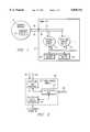
- FIG. 5is a block diagram of one embodiment of telephone control modules in a master/slave topology for use with standard telephones according to the teachings of the present invention.
- telephone network 10is coupled to user site 12.
- Telephone network 10can comprise a central office 14 that provides tip and ring signals across a telephone line to user site 12.
- site telephone line 60is coupled to central office 14 and extends to a plurality of telephone outlets 62.
- Telephone outlets 62can comprise standard RJ-11 wall outlets.
- Each telephone outlet 62can be coupled to a telephone control module (TCM) 64.
- TCMtelephone control module
- one telephone control module 64can be a TCM master and at least one other telephone control module 64 can be a TCM slave, as shown.
- TCM slave 64can comprise a telephone line interface 66, an electronic device interface 67, and a logic/control unit 68.
- Telephone line interface 66provides an interface to telephone outlet 62
- electronic device interface 67provides an interface to an electronic device 69.
- electronic device 69comprises a standard telephone.
- TCM slave 64can comprise a telephone line interface 66 and a logic/control unit 68.
- TCM slave 64can isolate telephone 69 from telephone outlet 62 and couple telephone 69 to telephone outlet 62.
- TCM master 64can manage the operation of TCM slave 64 to provide the control, communication and call processing features.
- Each logic/control unit 68is operable to monitor telephone outlet 62 and to control telephone line interface 66.
- Logic/control unit 68 in TCM slave 64is also operable to control electronic device interface 67.
- Each logic/control unit 68is operable to receive and transmit TCM network communications across the tip wire and/or ring wire of site telephone line 60.
- Telephone 69comprises a telephone connector 70 which can comprise an RJ-11 male connector.
- telephone control module 64 and telephone 69can be integrated into one device.
- the illustrated embodimentshows the placement of telephone control modules 64 where equipment, such as outlets and connectors, otherwise remain unmodified except for the addition of telephone control modules 64.
- Telephone 69comprises ringer detection circuitry 72 which is coupled to telephone connector 70. Switch hook contacts 74 are connected to ringer detection circuitry 72 and to the remaining part 76 of telephone 69. Telephone 69 can operate according to standard telephone operation as described above with respect to FIG. 4. It can be seen from FIG. 5 that the tip and ring wires of site telephone line 60 provide a physical electrical path between telephone control modules 64.
- Telephone control modules 64can communicate information with other telephone control modules 64 without degrading the operation of telephone 69 or telephone network 10. For example, by use of allowable frequencies and power levels, telephone control modules 64 can send and receive information between one another other without disturbing telephone 69 or telephone network 10.
- the topology of FIG. 5is a master/slave topology, other topologies such as a peer-to-peer topology are also possible.
- FIG. 6is a flow chart of one embodiment of a process for providing call processing features to a multi-station telephone system according to the teachings of the present invention.
- the process of FIG. 6can be implemented using the telephone control module (TCM) based user site network described above.
- TCMtelephone control module
- the process of FIG. 6is managed by a TCM master in a master/slave topology.
- step 80the TCM based user site network is in an idle state where no incoming call, outgoing call or non-call based call processing feature is in progress.
- step 82the network determines whether an incoming call is detected. If so, the network processes the incoming call in step 84. This incoming call processing is accomplished by communication between the telephone control modules. Incoming call processing can comprise routing the call to a selected electronic device, answering the call, providing access to voice mail or providing other appropriate control, communication or call processing feature. After processing the incoming call, the network returns to the idle state of step 80.
- step 86the network determines whether an outgoing call is detected. If so, the network processes the outgoing call in step 88. Outgoing call processing is also accomplished by communication between the telephone control modules. Outgoing call processing can comprise providing voice dialing, conferencing or other appropriate control, communication or call processing feature. After processing the outgoing call, the network again returns to the idle state of step 80.
- Non-call based call processing featurescan comprise features such as accessing voice mail functions, modifying or defining parameters of the telephone system, and recording messages for incoming calls.
- test messagesare sent periodically to check the integrity of the network.
- a TCM mastersends test messages to each TCM slave.
- Each TCM slavereceives the test message and returns a status message to the TCM master.
- the TCM masterthereby monitors the integrity of the network.
- the networkdetermines whether there has been a loss of integrity. If not, the network returns to the idle state of step 80. If integrity has been lost, the network can isolate itself from the multi-station telephone system to ensure no interference with normal operation.
- a user sitecan have at least one telephone connected to a TCM slave and a speech dialer connected to a TCM master.
- detecting and processing an outgoing callis the use of the speech dialer. The process could be initiated by a user picking up the telephone and pressing an appropriate key sequence. The attached TCM slave could detect this key sequence and communicate with the TCM master. The TCM master and TCM slave can then cooperate to provide user access to the speech dialer while remaining essentially transparent to the user. The TCM master and TCM slave can allow the user to use the speech dialer to place a telephone call, for example, to another electronic device located in the user site or to an external number.
- the telephone switch hookis closed when the user picks up the telephone receiver.
- a TCM slavecan keep the telephone isolated from the telephone line. This means that the central office of the public telephone network would not immediately detect the off-hook state.
- the TCM slaveUpon detecting the off-hook state, the TCM slave can communicate an information packet to a TCM master identifying itself as the originating TCM slave and notifying the TCM master of the off-hook status of the associated telephone.
- the TCM mastercan receive the information packet and direct the TCM slave to play an informational prompt to a user. For example, the user might hear: "Please dial a number or speak the name of the person you wish to call.” If the user dials a number, the dialing can be detected by the TCM slave which, in turn, can connect the telephone to the telephone line to allow normal dialing operation of the telephone.
- the usercan state the name of the person to call.
- the TCM slavecan send an information packet to the TCM master identifying the stated name, and the TCM master can forward that name to a speech dialer.
- the speech dialercan then indicate that the name was recognized by its voice recognizer and provide the telephone number to be dialed.
- the TCM mastercan issue an information packet to the TCM slave directing the TCM slave to connect the telephone to the telephone line.
- the central officeAfter connection, the central office then can detect the off-hook state and provide a dial tone. In response to the dial tone, the TCM master would dial the telephone number for the stated name.
- the TCM mastercan identify the number as associated with another telephone located at the user site. The TCM master can then direct the TCM slave attached to the other telephone to ring that telephone. If the called interior party answers, the TCM master and respective TCM slaves can provide a path between the user and the called interior party allowing communication within the user site without needing additional site telephone lines.
- the callscan be detected by a TCM master by monitoring the site telephone line such as tip and ring wiring.
- the TCM mastercan be set, for example, to answer all incoming calls after a predetermined number of rings.
- the TCM mastercan direct the call to a selected telephone or can direct the call to all of the telephones at the user site.
- the TCM masteralso can simply allow each TCM slave to determine on its own whether to connect an attached electronic device.
- the TCM mastercan collect and process caller ID information transmitted by the telephone network. This caller ID information can be useful for processing an incoming call based on stored knowledge concerning the calling party.
- the TCM mastercan be programmed to provide an automated attendant function. Initially, the TCM master can cause a prompt to be played to the caller that could direct the caller to speak a name or enter a number identifying the party the caller wants to reach. After receiving a response, the TCM master can inform the caller that the call is being processed, place the call on hold, and perform one of many functions.
- the TCM mastercould send an information packet to a selected TCM slave directing the TCM slave to cause an attached telephone to ring. In this manner, the call can be directed to a telephone associated with the called party.
- the TCM mastercould send an information packet to all TCM slaves directing each to cause an attached telephone to ring a distinctive ringing pattern unique to the called party.
- the TCM masteralso could send an information packet to a TCM slave that is attached to a speaker/microphone.
- the TCM slavecould play the recorded response of the caller.
- the called partycould then be prompted to respond whether the called party wanted to accept or reject the call. If the call is accepted, the TCM slave could connect the attached telephone. If the call is rejected, the TCM master could take control and direct the call to a voice mail system for accepting a message from the caller.
Landscapes
- Engineering & Computer Science (AREA)
- Signal Processing (AREA)
- Telephonic Communication Services (AREA)
Abstract
Description
Claims (44)
Priority Applications (1)
| Application Number | Priority Date | Filing Date | Title |
|---|---|---|---|
| US08/626,724US5809111A (en) | 1996-04-01 | 1996-04-01 | Telephone control module and user site network and methods of operation |
Applications Claiming Priority (1)
| Application Number | Priority Date | Filing Date | Title |
|---|---|---|---|
| US08/626,724US5809111A (en) | 1996-04-01 | 1996-04-01 | Telephone control module and user site network and methods of operation |
Publications (1)
| Publication Number | Publication Date |
|---|---|
| US5809111Atrue US5809111A (en) | 1998-09-15 |
Family
ID=24511564
Family Applications (1)
| Application Number | Title | Priority Date | Filing Date |
|---|---|---|---|
| US08/626,724Expired - Fee RelatedUS5809111A (en) | 1996-04-01 | 1996-04-01 | Telephone control module and user site network and methods of operation |
Country Status (1)
| Country | Link |
|---|---|
| US (1) | US5809111A (en) |
Cited By (25)
| Publication number | Priority date | Publication date | Assignee | Title |
|---|---|---|---|---|
| WO1999055065A1 (en)* | 1998-04-20 | 1999-10-28 | Premisenet Incorporated | Telephone control module and user site network and methods of operation |
| US6122347A (en)* | 1997-11-13 | 2000-09-19 | Advanced Micro Devices, Inc. | System and method for self-announcing a caller of an incoming telephone call |
| US6173041B1 (en)* | 1997-11-13 | 2001-01-09 | Advanced Micro Devices, Inc. | System and method for reducing call interruptions on a telephone |
| US6178230B1 (en)* | 1997-11-13 | 2001-01-23 | Advanced Micro Devices, Inc. | System and method for identifying a callee of an incoming telephone call |
| US6219411B1 (en)* | 1997-10-22 | 2001-04-17 | Ncr Corporation | Personal computer assisted multiple line access |
| US6304642B1 (en)* | 1999-06-08 | 2001-10-16 | Conexant Systems, Inc. | Peer-to-peer data transfer using pre-existing caller ID CLASS FSK signaling infrastructure |
| US6373925B1 (en)* | 1996-06-28 | 2002-04-16 | Siemens Aktiengesellschaft | Telephone calling party announcement system and method |
| US6385303B1 (en)* | 1997-11-13 | 2002-05-07 | Legerity, Inc. | System and method for identifying and announcing a caller and a callee of an incoming telephone call |
| US6389125B1 (en)* | 1998-12-04 | 2002-05-14 | Agere Systems Guardian Corp. | Shared information between multiple telephones |
| US6496569B2 (en)* | 1999-03-19 | 2002-12-17 | Ameritech Corporation | Method and system for providing enhanced caller identification and privacy management |
| US6539085B2 (en)* | 1999-10-26 | 2003-03-25 | Hewlett-Packard Company | Automatic phone line re-allocation |
| US6597764B1 (en)* | 1997-12-22 | 2003-07-22 | Brother Kogyo Kabushiki Kaisha | Communication device with main telecommunication unit that allows designation of a selected subsidiary telecommunication unit |
| US20030142795A1 (en)* | 2002-01-31 | 2003-07-31 | Gavette Sherman L. | Home network telephone answering system and method for same |
| US6618473B1 (en) | 2001-07-06 | 2003-09-09 | Dasym Technologies, Inc. | Telephone caller screening device |
| US20030179869A1 (en)* | 2002-03-20 | 2003-09-25 | Norifumi Yoshitani | Telephone communication apparatus |
| US6636586B1 (en)* | 1996-11-11 | 2003-10-21 | Winbond Electronics Corp. | Telephone set device capable of vocalizing a telephone number being called |
| US6721419B1 (en)* | 1999-06-09 | 2004-04-13 | Premisenet Incorporated | Method and system for selecting a frequency for communication within a premises network |
| US20040120489A1 (en)* | 2002-09-05 | 2004-06-24 | Siemens Aktiengesellschaft | Method and apparatus for controlling and/or monitoring a MULAP line |
| US6778549B1 (en)* | 2000-09-22 | 2004-08-17 | Advanced Micro Devices, Inc. | Coupling device connecting multiple pots lines in an HPNA environment |
| US6880012B1 (en) | 2000-08-02 | 2005-04-12 | International Business Machines Corporation | System, method, and program for establishing modem communication between a master computer system and a plurality of slave computer systems through a common serial communication channel |
| US6975713B1 (en)* | 2003-03-13 | 2005-12-13 | Vulcan Research LLC | Providing multiple line functionality using alternative network telephony |
| US20060112207A1 (en)* | 2004-11-25 | 2006-05-25 | Kawasaki Microelectronics, Inc. | Data transfer apparatus |
| US20080069323A1 (en)* | 2006-09-20 | 2008-03-20 | Sbc Knowledge Ventures, L.P. | Method for provisioning a terminal device in a multi-user setting |
| US20090239507A1 (en)* | 2007-08-31 | 2009-09-24 | William Joseph Sigmund | Systems and Methods for Providing Enhanced Voicemail Services |
| US20110085646A1 (en)* | 2008-06-30 | 2011-04-14 | At&T Mobility Ii Llc | Call Handling Treatment for Voicemail Systems |
Citations (10)
| Publication number | Priority date | Publication date | Assignee | Title |
|---|---|---|---|---|
| US4776006A (en)* | 1987-04-23 | 1988-10-04 | At&T Bell Laboratories | Multiplexed data channel controlled telephone system |
| US4807225A (en)* | 1987-02-02 | 1989-02-21 | American Telephone And Telegraph Company, At&T Technologies, Inc. | Telephone line carrier system |
| US5136585A (en)* | 1988-03-10 | 1992-08-04 | Northern Telecom Limited | Digital key telephone system |
| US5195086A (en)* | 1990-04-12 | 1993-03-16 | At&T Bell Laboratories | Multiple call control method in a multimedia conferencing system |
| US5263083A (en)* | 1990-12-10 | 1993-11-16 | Rolm Company | Method and apparatus for sharing speakerphone processor among multiple users |
| US5483577A (en)* | 1994-01-24 | 1996-01-09 | Advanced Micro Devices, Inc. | Single chip telephone answering machine, telephone, speakerphone, and ADSI controller |
| US5550900A (en)* | 1994-12-29 | 1996-08-27 | Lucent Technologies Inc. | Apparatus and method for routing messages in a telephone message center |
| US5566231A (en)* | 1994-10-27 | 1996-10-15 | Lucent Technologies Inc. | Apparatus and system for recording and accessing information received over a telephone network |
| US5566232A (en)* | 1994-10-27 | 1996-10-15 | Lucent Technologies Inc. | System and apparatus for recording and accessing information received over a phone network using a premises phone for control |
| US5596631A (en)* | 1994-10-05 | 1997-01-21 | Chen; Abraham Y. | Station controller for distributed single line PABX |
- 1996
- 1996-04-01USUS08/626,724patent/US5809111A/ennot_activeExpired - Fee Related
Patent Citations (10)
| Publication number | Priority date | Publication date | Assignee | Title |
|---|---|---|---|---|
| US4807225A (en)* | 1987-02-02 | 1989-02-21 | American Telephone And Telegraph Company, At&T Technologies, Inc. | Telephone line carrier system |
| US4776006A (en)* | 1987-04-23 | 1988-10-04 | At&T Bell Laboratories | Multiplexed data channel controlled telephone system |
| US5136585A (en)* | 1988-03-10 | 1992-08-04 | Northern Telecom Limited | Digital key telephone system |
| US5195086A (en)* | 1990-04-12 | 1993-03-16 | At&T Bell Laboratories | Multiple call control method in a multimedia conferencing system |
| US5263083A (en)* | 1990-12-10 | 1993-11-16 | Rolm Company | Method and apparatus for sharing speakerphone processor among multiple users |
| US5483577A (en)* | 1994-01-24 | 1996-01-09 | Advanced Micro Devices, Inc. | Single chip telephone answering machine, telephone, speakerphone, and ADSI controller |
| US5596631A (en)* | 1994-10-05 | 1997-01-21 | Chen; Abraham Y. | Station controller for distributed single line PABX |
| US5566231A (en)* | 1994-10-27 | 1996-10-15 | Lucent Technologies Inc. | Apparatus and system for recording and accessing information received over a telephone network |
| US5566232A (en)* | 1994-10-27 | 1996-10-15 | Lucent Technologies Inc. | System and apparatus for recording and accessing information received over a phone network using a premises phone for control |
| US5550900A (en)* | 1994-12-29 | 1996-08-27 | Lucent Technologies Inc. | Apparatus and method for routing messages in a telephone message center |
Cited By (70)
| Publication number | Priority date | Publication date | Assignee | Title |
|---|---|---|---|---|
| US6373925B1 (en)* | 1996-06-28 | 2002-04-16 | Siemens Aktiengesellschaft | Telephone calling party announcement system and method |
| US6636586B1 (en)* | 1996-11-11 | 2003-10-21 | Winbond Electronics Corp. | Telephone set device capable of vocalizing a telephone number being called |
| US6219411B1 (en)* | 1997-10-22 | 2001-04-17 | Ncr Corporation | Personal computer assisted multiple line access |
| US6122347A (en)* | 1997-11-13 | 2000-09-19 | Advanced Micro Devices, Inc. | System and method for self-announcing a caller of an incoming telephone call |
| US6173041B1 (en)* | 1997-11-13 | 2001-01-09 | Advanced Micro Devices, Inc. | System and method for reducing call interruptions on a telephone |
| US6178230B1 (en)* | 1997-11-13 | 2001-01-23 | Advanced Micro Devices, Inc. | System and method for identifying a callee of an incoming telephone call |
| US6385303B1 (en)* | 1997-11-13 | 2002-05-07 | Legerity, Inc. | System and method for identifying and announcing a caller and a callee of an incoming telephone call |
| US6711239B1 (en)* | 1997-11-13 | 2004-03-23 | Legerity, Inc. | System and method for identifying a callee of an incoming telephone call |
| US6704395B1 (en) | 1997-11-13 | 2004-03-09 | Legerity, Inc. | System and method for reducing call interruptions on a telephone |
| US6597764B1 (en)* | 1997-12-22 | 2003-07-22 | Brother Kogyo Kabushiki Kaisha | Communication device with main telecommunication unit that allows designation of a selected subsidiary telecommunication unit |
| WO1999055065A1 (en)* | 1998-04-20 | 1999-10-28 | Premisenet Incorporated | Telephone control module and user site network and methods of operation |
| US6389125B1 (en)* | 1998-12-04 | 2002-05-14 | Agere Systems Guardian Corp. | Shared information between multiple telephones |
| US7260196B2 (en) | 1999-03-19 | 2007-08-21 | Sbc Properties, L.P. | Method and system for providing enhanced caller identification and privacy management |
| US20050013424A1 (en)* | 1999-03-19 | 2005-01-20 | Sbc Properties, L.P. | Method and system for providing enhanced caller identification and privacy management |
| US6496569B2 (en)* | 1999-03-19 | 2002-12-17 | Ameritech Corporation | Method and system for providing enhanced caller identification and privacy management |
| US6304642B1 (en)* | 1999-06-08 | 2001-10-16 | Conexant Systems, Inc. | Peer-to-peer data transfer using pre-existing caller ID CLASS FSK signaling infrastructure |
| US6721419B1 (en)* | 1999-06-09 | 2004-04-13 | Premisenet Incorporated | Method and system for selecting a frequency for communication within a premises network |
| US6539085B2 (en)* | 1999-10-26 | 2003-03-25 | Hewlett-Packard Company | Automatic phone line re-allocation |
| US6880012B1 (en) | 2000-08-02 | 2005-04-12 | International Business Machines Corporation | System, method, and program for establishing modem communication between a master computer system and a plurality of slave computer systems through a common serial communication channel |
| US6778549B1 (en)* | 2000-09-22 | 2004-08-17 | Advanced Micro Devices, Inc. | Coupling device connecting multiple pots lines in an HPNA environment |
| US6618473B1 (en) | 2001-07-06 | 2003-09-09 | Dasym Technologies, Inc. | Telephone caller screening device |
| US20030142795A1 (en)* | 2002-01-31 | 2003-07-31 | Gavette Sherman L. | Home network telephone answering system and method for same |
| US7162013B2 (en)* | 2002-01-31 | 2007-01-09 | Sharp Laboratories Of America, Inc. | Home network telephone answering system and method for same |
| US7308086B2 (en)* | 2002-03-20 | 2007-12-11 | Sharp Kabushiki Kaisha | Telephone communication apparatus |
| US20030179869A1 (en)* | 2002-03-20 | 2003-09-25 | Norifumi Yoshitani | Telephone communication apparatus |
| US20080075272A1 (en)* | 2002-03-20 | 2008-03-27 | Norifumi Yoshitani | Telephone Communication Apparatus |
| US7567656B2 (en) | 2002-03-20 | 2009-07-28 | Sharp Kabushiki Kaisha | Telephone communication apparatus |
| US7257211B2 (en)* | 2002-09-05 | 2007-08-14 | Siemens Aktiengesellschaft | Method and apparatus for controlling and/or monitoring a MULAP line |
| US20040120489A1 (en)* | 2002-09-05 | 2004-06-24 | Siemens Aktiengesellschaft | Method and apparatus for controlling and/or monitoring a MULAP line |
| US6975713B1 (en)* | 2003-03-13 | 2005-12-13 | Vulcan Research LLC | Providing multiple line functionality using alternative network telephony |
| US20060112207A1 (en)* | 2004-11-25 | 2006-05-25 | Kawasaki Microelectronics, Inc. | Data transfer apparatus |
| US7519848B2 (en)* | 2004-11-25 | 2009-04-14 | Kawasaki Microelectronics, Inc. | Data transfer apparatus |
| US20080069323A1 (en)* | 2006-09-20 | 2008-03-20 | Sbc Knowledge Ventures, L.P. | Method for provisioning a terminal device in a multi-user setting |
| US8498393B2 (en)* | 2006-09-20 | 2013-07-30 | At&T Intellectual Property I, L.P. | Method for provisioning a terminal device in a multi-user setting |
| US20090253413A1 (en)* | 2007-08-31 | 2009-10-08 | William Joseph Sigmund | Systems and Methods for Providing Enhanced Voicemail Services |
| US8412162B2 (en) | 2007-08-31 | 2013-04-02 | At&T Mobility Ii Llc | Systems and methods for providing enhanced voicemail services |
| US20090253412A1 (en)* | 2007-08-31 | 2009-10-08 | William Joseph Sigmund | Systems and Methods for Providing Enhanced Voicemail Services |
| US20100159891A1 (en)* | 2007-08-31 | 2010-06-24 | William Joseph Sigmund | Enhanced Messaging With Language Translation Feature |
| US20100159888A1 (en)* | 2007-08-31 | 2010-06-24 | William Joseph Sigmund | Voicemail Forwarding Functionality for Communications Networks |
| US20100159890A1 (en)* | 2007-08-31 | 2010-06-24 | William Joseph Sigmund | Video Greetings for Voicemail Systems |
| US20100159886A1 (en)* | 2007-08-31 | 2010-06-24 | William Joseph Sigmund | Systems and Methods for Updating Voicemail With Selective Establishment of PDP Contexts and Data Sessions |
| US20100167699A1 (en)* | 2007-08-31 | 2010-07-01 | William Joseph Sigmund | Systems and Methods for Consolidating Wireline and Wireless Voicemail Boxes |
| US20100189229A1 (en)* | 2007-08-31 | 2010-07-29 | At&T Mobility Ii Llc | Toggling Voicemail Class of Service |
| US20100195807A1 (en)* | 2007-08-31 | 2010-08-05 | At&T Mobility Ii Llc | Secure Visual Voicemail |
| US20100222024A1 (en)* | 2007-08-31 | 2010-09-02 | At&T Mobility Ii Llc | Systems and Methods for Providing a Password Reset Feature |
| USRE46952E1 (en) | 2007-08-31 | 2018-07-10 | Nuance Communications, Inc. | Systems and methods for consolidating wireline and wireless voicemail boxes |
| US8306509B2 (en) | 2007-08-31 | 2012-11-06 | At&T Mobility Ii Llc | Enhanced messaging with language translation feature |
| US8340644B2 (en) | 2007-08-31 | 2012-12-25 | At&T Mobility Ii Llc | Voicemail forwarding functionality for communications networks |
| US8351903B2 (en) | 2007-08-31 | 2013-01-08 | At&T Mobility Ii, Llc | Updating voicemail with selective establishment of PDP contexts and data sessions |
| US8401526B2 (en) | 2007-08-31 | 2013-03-19 | At&T Mobility Ii Llc | Systems and methods for providing a password reset feature |
| US8406743B2 (en)* | 2007-08-31 | 2013-03-26 | At&T Mobility Ii Llc | Systems and methods for consolidating wireline and wireless voicemail boxes |
| US20090253407A1 (en)* | 2007-08-31 | 2009-10-08 | William Joseph Sigmund | Systems and Methods for Providing Enhanced Voicemail Services |
| US8442496B2 (en) | 2007-08-31 | 2013-05-14 | At&T Mobility Ii Llc | Enhanced messaging with language translation feature |
| US8478239B2 (en) | 2007-08-31 | 2013-07-02 | At&T Mobility Ii Llc | Video greetings for voicemail systems |
| US8489074B2 (en) | 2007-08-31 | 2013-07-16 | At&T Mobility Ii Llc | Systems and methods for providing enhanced voicemail services |
| US20090239507A1 (en)* | 2007-08-31 | 2009-09-24 | William Joseph Sigmund | Systems and Methods for Providing Enhanced Voicemail Services |
| US8503988B2 (en) | 2007-08-31 | 2013-08-06 | At&T Mobility Ii Llc | Systems and methods for providing a password reset feature |
| US8509745B2 (en) | 2007-08-31 | 2013-08-13 | At&T Mobility Ii Llc | Voicemail archival and forwarding functionality for communications networks and devices |
| US8515395B2 (en) | 2007-08-31 | 2013-08-20 | At&T Mobility Ii Llc | Systems and methods for providing enhanced voicemail services |
| US8548438B2 (en) | 2007-08-31 | 2013-10-01 | At&T Mobility Ii Llc | Systems and methods for providing enhanced voicemail services |
| US8688082B2 (en) | 2007-08-31 | 2014-04-01 | At&T Mobility Ii Llc | Systems and methods for consolidating wireline and wireless voicemail boxes |
| US8737580B2 (en) | 2007-08-31 | 2014-05-27 | At&T Mobility Ii Llc | Toggling voicemail class of service |
| US8798241B2 (en) | 2007-08-31 | 2014-08-05 | At&T Mobility Ii Llc | Secure visual voicemail |
| US9210558B2 (en) | 2007-08-31 | 2015-12-08 | At&T Mobility Ii Llc | Updating voicemail with selective establishment of PDP contexts and data sessions |
| US8831573B2 (en) | 2007-08-31 | 2014-09-09 | At&T Mobility Ii Llc | Video greetings for voicemail systems |
| US8843117B2 (en) | 2007-08-31 | 2014-09-23 | At&T Mobility Ii Llc | Voicemail archival and forwarding functionality for communications networks and devices |
| US8923825B2 (en) | 2007-08-31 | 2014-12-30 | At&T Mobility Ii Llc | Enhanced messaging with language translation feature |
| US8977241B2 (en) | 2007-08-31 | 2015-03-10 | At&T Mobility Ii Llc | Voicemail forwarding functionality for communications networks |
| US8798238B2 (en) | 2008-06-30 | 2014-08-05 | At&T Mobility Ii Llc | Call handling treatment for voicemail systems |
| US20110085646A1 (en)* | 2008-06-30 | 2011-04-14 | At&T Mobility Ii Llc | Call Handling Treatment for Voicemail Systems |
Similar Documents
| Publication | Publication Date | Title |
|---|---|---|
| US5809111A (en) | Telephone control module and user site network and methods of operation | |
| KR100188495B1 (en) | Method for performing intelligent network services , with an isdn network terminator located at a subscriber's premise | |
| US7020488B1 (en) | Communications unit, system and methods for providing multiple access to a wireless transceiver | |
| US6219409B1 (en) | Premises gateway and premises network interfaces for accessing subscriber premises equipment and communication networks using ring suppression | |
| US6167043A (en) | Method and system for small office and home office telephone private branch exchange allowing simultaneous data and voice communications | |
| US6937854B2 (en) | Apparatus for conducting a conference call between a wireless line and a land line using customer premise equipment | |
| US5737400A (en) | Telecommunications system for accessing subscriber premises equipment using ring suppression | |
| US7177664B2 (en) | Bluetooth interface between cellular and wired telephone networks | |
| US20050152347A1 (en) | System and method for managing voice communications between a telephone, a circuit switching network and/or a packet switching network | |
| EP1179945B1 (en) | Answer detection for ip based telephones using passive detection | |
| US6477248B1 (en) | Multi-line station interface | |
| US20010010716A1 (en) | Premises gateway and premises network interfaces for accessing subscriber premises equipment and communication networks using ring suppression | |
| JPS61274555A (en) | Exchange system | |
| US20040235518A1 (en) | Hybrid telephone network utilizing wireless link and landline services | |
| US20050260975A1 (en) | Telecommunications system and method for providing an automatic notification of availability of a communication device to establish a telephone call | |
| US6091721A (en) | Apparatus for telephone communication over plural channels | |
| WO1999055065A1 (en) | Telephone control module and user site network and methods of operation | |
| US5912950A (en) | Telephone network with normally off hook telephones | |
| USRE38596E1 (en) | Methods for performing intelligent network services with an ISDN network terminator located at a subscriber's premise | |
| US7023982B1 (en) | Telephone plug system | |
| CN1093365C (en) | Remote subscriber module capable of processing internal call and method for controlling the same | |
| WO2004049655A1 (en) | System and method for voice over ip communication | |
| CA2412768C (en) | Methods for performing intelligent network services with an isdn network terminator located at a subscriber's premise | |
| JP2000078312A (en) | Communications system | |
| JPH01233870A (en) | Telephone set |
Legal Events
| Date | Code | Title | Description |
|---|---|---|---|
| AS | Assignment | Owner name:MATTHEWS COMMUNICATIONS MANAGEMENT, INC., TEXAS Free format text:ASSIGNMENT OF ASSIGNORS INTEREST;ASSIGNOR:MATTHEWS, GORDON H.;REEL/FRAME:008542/0840 Effective date:19970522 | |
| AS | Assignment | Owner name:LOTH, ANTHONY J., AS SECURITY AGENT, TEXAS Free format text:SECURITY AGREEMENT;ASSIGNOR:MATTHEWS COMMUNICATIONS MANAGEMENT, INC.;REEL/FRAME:009278/0796 Effective date:19980625 | |
| AS | Assignment | Owner name:PREMISENET INCORPORATED, TEXAS Free format text:CHANGE OF NAME;ASSIGNOR:MATTHEWS COMMUNICATIONS MANAGEMENT, INC.;REEL/FRAME:010572/0578 Effective date:19991026 | |
| AS | Assignment | Owner name:LOTH, ANTHONY J., SECURITY AGENT, TEXAS Free format text:SECURITY INTEREST;ASSIGNOR:PREMISENET INCORPORATED;REEL/FRAME:011064/0077 Effective date:19980625 | |
| FPAY | Fee payment | Year of fee payment:4 | |
| REMI | Maintenance fee reminder mailed | ||
| REMI | Maintenance fee reminder mailed | ||
| FPAY | Fee payment | Year of fee payment:8 | |
| SULP | Surcharge for late payment | Year of fee payment:7 | |
| AS | Assignment | Owner name:LOTH, ANTHONY J., TEXAS Free format text:ASSIGNMENT OF ASSIGNORS INTEREST;ASSIGNOR:PREMISENET INCORPORATED;REEL/FRAME:021018/0897 Effective date:20020624 Owner name:RCD INVESTMENTS NO. 2, LTD., TEXAS Free format text:ASSIGNMENT OF ASSIGNORS INTEREST;ASSIGNOR:LOTH, ANTHONY J.;REEL/FRAME:021018/0915 Effective date:20080530 | |
| AS | Assignment | Owner name:LOTH, ANTHONY J, TEXAS Free format text:CORRECTION TO CONVEYING PARTY AND EXECUTION DATE OF PREVIOUSLY RECORDED SECURITY INTEREST ON REEL 011064 AND FRAME 0077.;ASSIGNOR:MATTHEWS COMMUNICATIONS MANAGEMENT, INC.;REEL/FRAME:021679/0445 Effective date:19980629 | |
| FEPP | Fee payment procedure | Free format text:PAT HOLDER NO LONGER CLAIMS SMALL ENTITY STATUS, ENTITY STATUS SET TO UNDISCOUNTED (ORIGINAL EVENT CODE: STOL); ENTITY STATUS OF PATENT OWNER: LARGE ENTITY | |
| FEPP | Fee payment procedure | Free format text:PAYOR NUMBER ASSIGNED (ORIGINAL EVENT CODE: ASPN); ENTITY STATUS OF PATENT OWNER: LARGE ENTITY | |
| AS | Assignment | Owner name:MATTHEWS COMMUNICATIONS MANAGEMENT, INC., TEXAS Free format text:CONFIRMATORY ASSIGNMENT;ASSIGNOR:MATTHEWS, MONIKA S. (EXECUTOR);REEL/FRAME:021901/0918 Effective date:20081124 | |
| AS | Assignment | Owner name:VELTRA REMOTE DE, L.L.C., DELAWARE Free format text:ASSIGNMENT OF ASSIGNORS INTEREST;ASSIGNOR:RCD INVESTMENTS NO. 2, LTD.;REEL/FRAME:022034/0810 Effective date:20080911 | |
| FEPP | Fee payment procedure | Free format text:ENTITY STATUS SET TO UNDISCOUNTED (ORIGINAL EVENT CODE: BIG.); ENTITY STATUS OF PATENT OWNER: LARGE ENTITY | |
| REMI | Maintenance fee reminder mailed | ||
| LAPS | Lapse for failure to pay maintenance fees | ||
| STCH | Information on status: patent discontinuation | Free format text:PATENT EXPIRED DUE TO NONPAYMENT OF MAINTENANCE FEES UNDER 37 CFR 1.362 | |
| FP | Lapsed due to failure to pay maintenance fee | Effective date:20100915 |