US5809021A - Multi-service switch for a telecommunications network - Google Patents
Multi-service switch for a telecommunications networkDownload PDFInfo
- Publication number
- US5809021A US5809021AUS08/664,994US66499496AUS5809021AUS 5809021 AUS5809021 AUS 5809021AUS 66499496 AUS66499496 AUS 66499496AUS 5809021 AUS5809021 AUS 5809021A
- Authority
- US
- United States
- Prior art keywords
- bus
- overlay
- slotted
- packet
- isochronous
- Prior art date
- Legal status (The legal status is an assumption and is not a legal conclusion. Google has not performed a legal analysis and makes no representation as to the accuracy of the status listed.)
- Expired - Lifetime
Links
Images


Classifications
- H—ELECTRICITY
- H04—ELECTRIC COMMUNICATION TECHNIQUE
- H04L—TRANSMISSION OF DIGITAL INFORMATION, e.g. TELEGRAPHIC COMMUNICATION
- H04L12/00—Data switching networks
- H04L12/54—Store-and-forward switching systems
- H04L12/56—Packet switching systems
- H04L12/5601—Transfer mode dependent, e.g. ATM
- H—ELECTRICITY
- H04—ELECTRIC COMMUNICATION TECHNIQUE
- H04J—MULTIPLEX COMMUNICATION
- H04J3/00—Time-division multiplex systems
- H04J3/16—Time-division multiplex systems in which the time allocation to individual channels within a transmission cycle is variable, e.g. to accommodate varying complexity of signals, to vary number of channels transmitted
- H04J3/1605—Fixed allocated frame structures
- H04J3/1611—Synchronous digital hierarchy [SDH] or SONET
- H—ELECTRICITY
- H04—ELECTRIC COMMUNICATION TECHNIQUE
- H04L—TRANSMISSION OF DIGITAL INFORMATION, e.g. TELEGRAPHIC COMMUNICATION
- H04L12/00—Data switching networks
- H04L12/64—Hybrid switching systems
- H—ELECTRICITY
- H04—ELECTRIC COMMUNICATION TECHNIQUE
- H04L—TRANSMISSION OF DIGITAL INFORMATION, e.g. TELEGRAPHIC COMMUNICATION
- H04L12/00—Data switching networks
- H04L12/64—Hybrid switching systems
- H04L12/6402—Hybrid switching fabrics
- H—ELECTRICITY
- H04—ELECTRIC COMMUNICATION TECHNIQUE
- H04Q—SELECTING
- H04Q11/00—Selecting arrangements for multiplex systems
- H04Q11/04—Selecting arrangements for multiplex systems for time-division multiplexing
- H04Q11/0428—Integrated services digital network, i.e. systems for transmission of different types of digitised signals, e.g. speech, data, telecentral, television signals
- H04Q11/0478—Provisions for broadband connections
- H—ELECTRICITY
- H04—ELECTRIC COMMUNICATION TECHNIQUE
- H04J—MULTIPLEX COMMUNICATION
- H04J2203/00—Aspects of optical multiplex systems other than those covered by H04J14/05 and H04J14/07
- H04J2203/0001—Provisions for broadband connections in integrated services digital network using frames of the Optical Transport Network [OTN] or using synchronous transfer mode [STM], e.g. SONET, SDH
- H04J2203/0089—Multiplexing, e.g. coding, scrambling, SONET
- H—ELECTRICITY
- H04—ELECTRIC COMMUNICATION TECHNIQUE
- H04L—TRANSMISSION OF DIGITAL INFORMATION, e.g. TELEGRAPHIC COMMUNICATION
- H04L12/00—Data switching networks
- H04L12/54—Store-and-forward switching systems
- H04L12/56—Packet switching systems
- H04L12/5601—Transfer mode dependent, e.g. ATM
- H04L2012/5603—Access techniques
- H04L2012/5609—Topology
- H04L2012/5613—Bus (including DQDB)
- H—ELECTRICITY
- H04—ELECTRIC COMMUNICATION TECHNIQUE
- H04L—TRANSMISSION OF DIGITAL INFORMATION, e.g. TELEGRAPHIC COMMUNICATION
- H04L12/00—Data switching networks
- H04L12/54—Store-and-forward switching systems
- H04L12/56—Packet switching systems
- H04L12/5601—Transfer mode dependent, e.g. ATM
- H04L2012/5638—Services, e.g. multimedia, GOS, QOS
- H04L2012/5646—Cell characteristics, e.g. loss, delay, jitter, sequence integrity
- H04L2012/5652—Cell construction, e.g. including header, packetisation, depacketisation, assembly, reassembly
- H04L2012/5653—Cell construction, e.g. including header, packetisation, depacketisation, assembly, reassembly using the ATM adaptation layer [AAL]
- H04L2012/5658—Cell construction, e.g. including header, packetisation, depacketisation, assembly, reassembly using the ATM adaptation layer [AAL] using the AAL5
- H—ELECTRICITY
- H04—ELECTRIC COMMUNICATION TECHNIQUE
- H04L—TRANSMISSION OF DIGITAL INFORMATION, e.g. TELEGRAPHIC COMMUNICATION
- H04L12/00—Data switching networks
- H04L12/54—Store-and-forward switching systems
- H04L12/56—Packet switching systems
- H04L12/5601—Transfer mode dependent, e.g. ATM
- H04L2012/5638—Services, e.g. multimedia, GOS, QOS
- H04L2012/5665—Interaction of ATM with other protocols
- H—ELECTRICITY
- H04—ELECTRIC COMMUNICATION TECHNIQUE
- H04L—TRANSMISSION OF DIGITAL INFORMATION, e.g. TELEGRAPHIC COMMUNICATION
- H04L12/00—Data switching networks
- H04L12/54—Store-and-forward switching systems
- H04L12/56—Packet switching systems
- H04L12/5601—Transfer mode dependent, e.g. ATM
- H04L2012/5672—Multiplexing, e.g. coding, scrambling
- H—ELECTRICITY
- H04—ELECTRIC COMMUNICATION TECHNIQUE
- H04L—TRANSMISSION OF DIGITAL INFORMATION, e.g. TELEGRAPHIC COMMUNICATION
- H04L12/00—Data switching networks
- H04L12/54—Store-and-forward switching systems
- H04L12/56—Packet switching systems
- H04L12/5601—Transfer mode dependent, e.g. ATM
- H04L2012/5678—Traffic aspects, e.g. arbitration, load balancing, smoothing, buffer management
- H04L2012/5679—Arbitration or scheduling
Definitions
- This inventionrelates in general to the field of telecommunications networks, and more particularly to a multi-service switch for a telecommunications network.
- a telecommunications environmentincludes two or more entities that are interconnected and communicate through various telecommunications services.
- the entitiesare interconnected to allow communication of information back and forth.
- Telecommunications networksprovide the means for communication of voice, video, facsimile or computer data information between separate entities connected to the networks.
- a particular telecommunications networkmay provide support for one or more of these types of telecommunications information.
- busconnecting the entities.
- busesmay be time multiplexed such that the data stream passing along the bus is divided into time slots, and information from one entity to another is transmitted in these discrete time slots.
- the telecommunications information transmitted between entitiesbreaks down into two broad types of services, namely asynchronous and isochronous services. Isochronous services require predictable periodic access to a network bus.
- Asynchronous servicesby contrast are all those that support bursty information types such as, for instance, packet services or asynchronous transfer mode (ATM) circuit emulation.
- ATMasynchronous transfer mode
- some bus structuresthat support transmission of both isochronous and asynchronous service formats.
- some ring bus structuressuch as a slotted ring, dedicate some bus time slots to isochronous and some bus time slots to asynchronous service formats.
- Other non-ring bus structuresalso dedicate each bus time slot to either isochronous or asynchronous service formats.
- a control messagemust be sent to each entity on the network to change the map of the bus time slots. This causes disruption of communication while administration overhead processes the mapping change.
- a multi-service switch for a telecommunications networkis provided that substantially eliminates or reduces disadvantages and problems associated with prior switches.
- a multi-service switch for a telecommunications networkhas an ingress portion and an egress portion.
- the system busis operable to carry data in a plurality of time slots.
- a system bus controlcomprises a head-of-bus control having an output. The output of the head-of-bus control is coupled to the ingress portion of the system bus.
- the head-of-bus controlis operable to configure and control the plurality of time slots.
- the system bus controlalso comprises a tail-of-bus control coupled to the head-of-bus control.
- the tail-of-bus controlhas an input coupled to the egress portion of the system bus.
- the tail-of-bus controlis operable to receive data from the egress portion of the system bus.
- a plurality of interface moduleseach have an input and an output.
- the input of each interface moduleis coupled to the egress portion of the system bus, and the output of each interface module is coupled to the ingress portion of the system bus.
- Each interface moduleis operable to perform distributed switching to communicate telecommunications information on the system bus.
- An ingress/egress bridgehas an input and an output. The input of the ingress/egress bridge is coupled to the ingress portion of the system bus, and the output of the ingress/egress bridge is coupled to the egress portion of the system bus. The ingress/egress bridge is operable to bridge the ingress portion to the egress portion of the system bus.
- a technical advantage of the present inventionis the configuration of a bus in a telecommunications network to support a plurality of types of telecommunications services having unique data formats.
- Another technical advantage of the present inventionis the dynamic allocation of time slots on a bus between isochronous services and asynchronous services with no disruption in data transmission.
- Another technical advantage of the present inventionis the interworking of different service types, that is, the transformation of telecommunications information received in a first format to a second format for transmission in the second format to other entities in the network.
- Another technical advantage of the present inventionis the transformation of all telecommunications information into one of a plurality of data formats for transmission on a single physical bus in a telecommunications network services platform.
- FIG. 1illustrates a block diagram of a multi-service switch for a telecommunications network constructed according to the teachings of the present invention
- FIG. 2illustrates an example of a single chassis for implementing a multi-service switch for a telecommunications network constructed according to the teachings of the present invention
- FIG. 3illustrates a block diagram of a multi-service switch for a telecommunications network having an extended bus constructed according to the teachings of the present invention
- FIG. 4illustrates a block diagram of a telecommunications environment utilizing multi-service switches for a telecommunications network constructed according to the teachings of the present invention
- FIG. 5aillustrates three bus overlays on a physical slotted bus according to the teachings of the present invention
- FIG. 5billustrates allocation of bus time slots between three bus overlays according to the teachings of the present invention
- FIG. 6aillustrates an asynchronous packet bus overlay datagram format according to the teachings of the present invention
- FIG. 6billustrates an asynchronous datagram header format according to the teachings of the present invention
- FIG. 6cillustrates a header field within an asynchronous transfer mode cell carried by the asynchronous packet bus overlay datagram according to the teachings of the present invention
- FIG. 6dillustrates formats for a destination address field within the packet bus overlay datagram according to the present invention
- FIG. 6eillustrates a block diagram of packet bus overlay entity to packet bus overlay entity unicast datagram communication
- FIG. 7illustrates congestion in an output buffer
- FIG. 8aillustrates a block diagram of a backoff protocol according to the teachings of the present invention
- FIG. 8billustrates a backoff message format according to the teachings of the present invention
- FIG. 8cillustrates a probability density function of backoff times according to one embodiment of the present invention
- FIG. 9aillustrates a stack diagram of a wideband isochronous overlay according to the teachings of the present invention.
- FIG. 9billustrates a diagram of a wideband overlay payload envelope according to the teachings of the present invention.
- FIG. 9cillustrates adaption of a STS-1 Synchronous Payload Envelope (SPE) to an isochronous wideband bus overlay data format according to the teachings of the present invention
- FIG. 9dillustrates adaption of a TU-3 to an isochronous wideband bus overlay data format according to the teachings of the present invention
- FIG. 10aillustrates an isochronous narrowband bus overlay data format according to the teachings of the present invention
- FIG. 10billustrates a narrowband structure of a signaling multiframe for trunks not carrying compressed voice data
- FIG. 10cillustrates an isochronous narrowband bus overlay data format for compressed voice channels according to the teachings of the present invention
- FIG. 10dillustrates the number of signaling bytes needed for various compression schemes.
- FIG. 10eillustrates a mapping of compressed channel signaling to the system multiframe according to the teachings of the present invention.
- a multi-service switch for a telecommunications network constructed according to the teachings of the present inventionprovides a single integrated platform that facilitates the provision of a variety of telecommunications information services to diverse entities simultaneously.
- the multi-service switch of the present inventionspecifically supports both isochronous services and asynchronous services using a single physical bus.
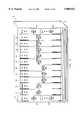
- FIG. 1illustrates a block diagram of a multi-service switch for a telecommunications network indicated generally at 10 constructed according to the teachings of the present invention.
- a bus controller 11has a head-of-bus control 12, a tail-of-bus control 15, and an arbiter 17.
- a slotted bus 13has an ingress portion 14 and an egress portion 16. Ingress portion 14 is coupled to an output of head-of-bus control 12, and egress portion 16 is coupled to an input of tail-of-bus control 15.
- An ingress/egress bridge 18has an input and an output. The input of ingress/egress bridge 18 is coupled to ingress portion 14 of slotted bus 13, and the output of ingress/egress bridge 18 is coupled to egress portion 16 of slotted bus 13.
- a second bus controller 19has a second head-of-bus control 20, a second tail-of-bus control 23, and a second arbiter 25.
- a second slotted bus 21has an ingress portion 22 and an egress portion 24. Ingress portion 22 is coupled to an output of head-of-bus control 20, and egress portion 24 is coupled to an input of tail-of-bus control 23.
- a second ingress/egress bridge 26has an input and an output. The input of ingress/egress bridge 26 is coupled to ingress portion 22 of slotted bus 21, and the output of ingress/egress bridge 26 is coupled to egress portion 24 of slotted bus 21.
- a number of interface modules 28 1 through 28 nare connected to slotted bus 13 and slotted bus 21 as shown.
- Each interface module 28 1 through 28 nhas a first input coupled to egress portion 16 of first slotted bus 13, a first output coupled to ingress portion 14 of first slotted bus 13, a second input coupled to egress portion 24 of second slotted bus 21, and a second output coupled to ingress portion 22 of second slotted bus 21.
- Each interface module 28includes a portion of a distributed switch that has multiple input and output queues interconnected by the dual buses through the inputs and outputs of each interface module.
- multi-service switch 10operates to support communication between interface modules 28 1 through 28 n via slotted bus 13 and slotted bus 21.
- Head-of-bus control 12 and head-of-bus control 20operate to generate the timing and controls necessary to configure time slots on slotted bus 13 and slotted bus 21 to allow communication over a number of bus overlays associated with different telecommunications data formats.
- Ingress/egress bridge 18 and ingress/egress bridge 26operate to connect ingress portion 14 and egress portion 16 of slotted bus 13 and to connect ingress portion 22 and egress portion 24 of slotted bus 21.
- Bus 13 and bus 21operate in a redundant manner to route data communication to and from interface modules 28 1 through 28 n . The use of redundant buses 13 and 21 provide for the continued operation of switch 10 in the event that either bus 13 or 21 fail for any reason.
- Multi-service switch 10consists of a pair of slotted buses 13 and 21.
- each slotted busoperates at a nominal speed of 800 megabits per second (Mbps), for a combined speed of 1.6 gigabits per second (Gbps).
- slotted bus 13 and slotted bus 21are both identically formatted into two hundred time slots of sixty-four octets each and framed at a repetitive rate of 8 KHz.
- Slotted bus 13 and slotted bus 21are formed from unidirectional ingress portions 14 and 22 and unidirectional egress portions 16 and 24 extending the entire length of the attached interface modules 28 1 through 28 n , with the ingress portions 14 and 22 and the egress portions 16 and 24 connected together by ingress/egress bridges 18 and 26.
- multi-service switch 10is contained in a chassis or a cluster.
- a chassisis a number of interface modules coupled with head-of-bus controls and ingress/egress bridges.
- a clusteris a collection of one to four chassis all sharing the same slotted buses.
- Head-of-bus control 12 and head-of-bus control 20create the timing and control for ingress portions 14 and 22.
- Ingress/egress bridges 18 and 26generate the timing and control for egress portions 16 and 24 connecting the ingress portions to the egress portions retiming each signal with derived egress portion timing.
- Every interface module 28 1 through 28 n residing in a chassis or a clusterinterfaces to both slotted bus 13 and slotted bus 21 using ingress portions 14 and 22 to source incoming traffic into the system of multi-service switch 10 and using egress portions 16 and 24 to sink outgoing traffic from the system of multi-service switch 10.
- Slotted bus 13 and slotted bus 21are hybrid in nature in that the bus time slots are individually allocated to support one of two major types of telecommunications service categories, isochronous services or asynchronous services.
- Isochronous servicesare telecommunications services-that require predictable and periodic access to the slotted buses. All circuit services are included in this category and are supported via two isochronous overlays using a portion of reserved bandwidth of slotted buses 13 and 21.
- Asynchronous servicesare those that support bursty telecommunications information. All packet services including asynchronous transfer mode (ATM) services are supported by an asynchronous overlay using the remainder of the slotted bus bandwidth not reserved for isochronous services.
- ATMasynchronous transfer mode
- the bandwidth of the slotted buses 13 and 21is allocated to isochronous or asynchronous services with a granularity of one time slot by designating each time slot as reserved either for isochronous or asynchronous access. These two categories of telecommunications services are therefore entirely isolated from each other although they may share neighboring time slots on the same physical buses. Isochronous time slots are allocated for the exclusive use of circuit services. Since isochronous bandwidth is not shared with asynchronous bandwidth, no performance degradation is experienced by circuit services due to the presence of statistical traffic on slotted bus 13 and 21.
- Time slots on slotted buses 13 and 21are dynamically allocated to either isochronous services or asynchronous services. All time slots are initially allocated to asynchronous services until the need for an isochronous time slot arises. At this point, the necessary number of time slots are reserved for isochronous services. This reservation is communicated to interface modules 28 1 through 28 n by head of bus control 12 and 20 via a single signal transported in parallel with other slot timing information down the slotted bus. The time slots reserved for isochronous access are no longer part of the asynchronous bandwidth. After reserving time slots for isochronous use, the isochronous services are assigned octets within the reserved time slots to effect the connections needed. Reallocation of the isochronous time slots back to asynchronous services requires the assignments of octets to be removed. Once these assignments are removed and the time slots are cleared of isochronous traffic, the time slots again can be allocated to asynchronous services.
- Virtual buses of variable bandwidth capacityare overlaid on physical slotted buses 13 and 21 by this allocation of individual time slots to one or another access category.
- This allocation of time slots to create virtual busesis referred to as a bus overlay.
- three unique bus overlaysare implemented: (1) a narrowband bus overlay (NBO) for narrowband isochronous services, (2) a wideband bus overlay (WBO) which includes from wideband to broadband isochronous services, and (3) a packet bus overlay (PBO) for asynchronous services.
- NBOnarrowband bus overlay
- WBOwideband bus overlay
- PBOpacket bus overlay
- Each of these bus overlayssupports a different classification of telecommunications traffic and is formed by concatenating a variable number of bus time slots.
- Each bus overlayimplements a unique protocol for access to and from the overlay.
- the narrowband bus overlay and the wideband bus overlayuse time slots reserved for isochronous use.
- the narrowband bus overlayoccupies a variable number of isochronous time slots excluding those reserved for the wideband bus overlay, and services narrowband telecommunications connections. Narrowband connections are those operating at DSO and N ⁇ 56/64 kpbs rates.
- the wideband bus overlayoccupies a variable number of isochronous slots excluding those reserved for the narrowband bus overlay, and services SONET/SDH connection as well as DS1/DS3 level multiplexing and cross-connecting. The remaining time slots not reserved for isochronous use are available to the packet bus overlay for use by asynchronous traffic.
- the packet bus overlayoccupies the time slots not explicitly reserved for isochronous use. This bandwidth forms a common pool shared among all interface modules requesting access to asynchronous time slots of the packet bus overlay. A minimum amount of bus bandwidth must always be made available for asynchronous access because internal management and control communications utilize the packet bus overlay.
- Redundant bandwidthis allocated on slotted bus 13 and slotted bus 21 by making equivalent allocations on both buses when time slots are provisioned for isochronous services.
- the isochronous time slotsrepeat with a periodicity of 125 microseconds.
- Time slot interchanges (TSI)of any size are implemented by the concatenation of selected isochronous time slots.
- Isochronous interface modules accessing the narrowband and wideband bus overlayshave the ability to simultaneously access both slotted buses 13 and 21 transmitting the same information on both buses, and receiving the same information from both buses. In this way, full redundancy for isochronous circuit-based services is implemented.
- Asynchronous time slots in both slotted buses 13 and 21form a common pool of bandwidth for the packet bus overlay with a combined capacity of up to 1.6 Gbps.
- Asynchronous interface moduleshave access to both slotted bus 13 and slotted bus 21 for transmission and reception.
- individual packets or cellsare placed onto one of the two slotted buses based upon a load-sharing algorithm that assigns each virtual asynchronous connection to one of the slotted buses.
- Interface modules 28 1 to 28 nreceive the packets from either bus simultaneously, merging the packet streams from both buses into a single stream.
- virtual connections assigned to the failed busare automatically switched over to the surviving bus.
- interface modulesreceive packets from the surviving bus only. In this way, full redundancy for asynchronous services is implemented.
- An interface module 28 1 through 28 ndelineates bus time slots, frames, and multiframes on slotted bus 13 and slotted bus 21 to access properly the slotted buses.
- Each interface module 28 1 through 28 nis operable to determine, from head-of-bus control signals, the current time slot number and the time slot type.
- Head-of-bus control 12 and head-of-bus control 20operate to create the timing and control signals necessary to facilitate these functions of the interface modules 28 1 through 28 n on ingress portions 14 and 22 of slotted bus 13 and slotted bus 21.
- Ingress/egress bridge 18 and 26create the timing and control signals for egress portions 16 and 24 of slotted bus 13 and slotted bus 21 with each signal derived from its associated counterpart on the ingress portions 14 and 22 of slotted bus 13 and slotted bus 21. This is accomplished by regenerating the equivalent ingress portion signals onto the egress portion of buses 13 and 21.
- a system bus transfer clock signalis associated with both ingress portions 14 and 22 and egress portions 16 and 24 of slotted bus 13 and slotted bus 21 and is transported in parallel with the data on slotted buses 13 and 21 to all interface modules 28 1 through 28 n within a chassis or cluster.
- the system bus transfer clock signalsynchronizes the timing for access and exchange of both data and control signals of slotted buses 13 and 21.
- Interface modules 28 1 through 28 nuse an associated ingress system bus transfer clock to clock data onto ingress portions 14 and 22 of slotted buses 13 and 21 at designated intervals whether the access is an asynchronous or isochronous access.
- interface modules 28 1 through 28 nuse an associated system bus transfer egress clock to sample data from slotted buses 13 and 21 at designated intervals whether the access is an asynchronous or isochronous access.
- the system bus transfer clock signalhas a nominal frequency of 25.6 MHz, which equates to a 39.1 nanoseconds cycle time, and is derived from a centralized system synchronization reference signal.
- the timing for both slotted buses 13 and 21are generated from the same synchronization reference signal.
- the timing of independent slotted buses 13 and 21are synchronous one to another with the exception of some minimal intrinsic jitter imposed by clock generation circuitry. This synchronization between slotted buses 13 and 21 is necessary to allow non-destructive manual redundant slotted bus switchovers for isochronous traffic in the narrowband and wideband bus overlays.
- a slot synchronization pulseis associated with both ingress portions 14 and 22 and egress portions 16 and 24 of slotted bus 13 and 21 and is transported in parallel with slotted buses 13 and 21 to all interface modules 28 1 through 28 n within a chassis or cluster.
- the slot synchronization pulseis a synchronization signal generated by head-of-bus control 12 and 20, utilized to delineate time slots on the associated ingress portions 14 and 22 or egress portions 16 and 24.
- the pulseis repeated once every time slot, every sixteen bus clock cycles, and identifies the beginning and ending boundaries of time slots on slotted buses 13 and 21.
- Interface modules that require isochronous accessare assigned bandwidth in a time division multiplexed (TDM) fashion. Such interface modules are assigned access to specifically numbered time slots or a portion thereof in every frame. Therefore, these interface modules are explicitly aware of the relative number of the current time slot within the frame at all times. Rather than busing a tag or count in parallel with the data on the slotted buses 13 and 21 to identify the time slot number within the frame, each isochronous interface module derives the current time slot number using a frame synchronization pulse and the slot synchronization pulse.
- TDMtime division multiplexed
- An isochronous slot reservation signalis associated with both ingress portions 14 and 22 and egress portions 16 and 24 of slotted buses 13 and 21 and is transported in parallel with slotted buses 13 and 21 to all interface modules 28 1 through 28 n within a chassis or cluster.
- the isochronous slot reservation signalgives notification to all interface modules 28 1 through 28 n in a chassis or cluster, one time slot interval in advance, of whether a time slot is reserved for isochronous access.
- the isochronous slot reservation signalis active for an entire time slot interval if the subsequent bus time slot is reserved for isochronous access.
- This signalis not essential for asynchronous access on ingress portions 14 and 22 due to the fact that an explicit bus access grant is given to an interface module 28 1 through 28 n for asynchronous access, and an implicit bus access grant is assigned based on the time slot position within the frame or multiframe for isochronous access.
- all interface modules 28 1 through 28 nare operable to check the state of the isochronous slot reservation signal prior to transmitting onto the bus to add a measure of security to the operation of both the ingress and egress portions of buses 13 and 21.
- a system bus frame synchronous pulseis associated with both ingress portions 14 and 22 and egress portions 16 and 24 of slotted buses 13 and 21 and is transported in parallel with data to all interface modules 28 1 through 28 n within a chassis or cluster.
- This pulseis a synchronization signal generated by head-of-bus control 12 and 20, and delineates frames on slotted buses 13 and 21.
- the pulseis repeated every 125 microseconds and identifies the beginning and ending boundaries of a frame on one of the slotted buses 13 and 21.
- a system bus multiframe synchronization pulseis associated with both ingress portions 14 and 22 and egress portions 16 and 24 of slotted buses 13 and 21 and is transported in parallel with data on slotted buses 13 and 21 to all interface modules 28 1 through 28 n within a chassis or cluster.
- This pulseis generated by head-of-bus 12 and 20 and delineates multiframes which are contiguous blocks of 48 frames on slotted buses 13 and 21. This pulse is repeated every six milliseconds.
- the multiframe synchronization pulseidentifies the beginning and ending boundaries of a multiframe on slotted buses 13 and 21.
- the multiframe structureis utilized by the narrowband bus overlay to efficiently encode signaling information onto the slotted buses 13 and 21.
- Arbitration in the multiservice switch 10is executed by two centralized arbiters, a first bus A arbiter 17 arbitrating access to the asynchronous overlay on bus A, and a second bus B arbiter 25 regulating access to bus B.
- An output of interface modules 28 1 to 28 nis connected to a multiplexed request A bus 27. Multiplexed request A bus 27 is connected to an input of bus A arbiter 17.
- An output of bus A arbiter 17is connected to a grant A signal 29.
- the grant A signal 29is in turn connected to an input of each interface module 28 1 to 28 n .
- a second output of interface modules 28 1 to 28 nis connected to a multiplexed request B bus 31.
- the request B bus 31is in turn connected to an input of bus B arbiter 25.
- bus B arbiter 25An output of bus B arbiter 25 is connected to a grant B signal 33.
- the grant B signal 33is connected to an input of each interface module 28 1 to 28 n
- Interface modules 28 1 to 28 nissue requests to transmit datagram packets into buses A or B according to the bus selection assigned to each datagram by the load sharing algorithm. Multiple simultaneous requests for transmission of different datagrams of different classes of services into bus A or B may be issued by each interface module 28 1 to 28 n .
- Bus arbiters 17 and 25operating independently of each other, issue grants to specific interface modules to access individual asynchronous time slots, as disclosed in copending U.S. patent application, Ser. No. 08/228,513, now U.S. Pat. No. 5,463,624, entitled "A Bus Arbitration Method for Telecommunications Switching".
- multi-service switch 10consists of physically identical but independent slotted buses 13 and 21. Each is coupled to independent head-of-bus/tail-of-bus controls 12, 15 and 20, 23 and provides independent bandwidth capacity of 800 Mbps. Both slotted buses 13 and 21 provide support for isochronous circuit-based and asynchronous packet-based telecommunications services. These services differ in the manner in which they utilize slotted buses 13 and 21, in the way that service is provided, and in the manner in which redundancy is handled.
- slotted buses 13 and 21are completely one-for-one redundant resources.
- One slotted busis the active isochronous virtual bus and carries all circuit-based traffic within multi-service switch 10.
- the otheris the redundant isochronous virtual bus and remains on standby prepared to assume active status in the event of a failure on the currently active bus.
- Completely redundant isochronous bandwidthis reserved and transmitted simultaneously on both slotted buses 13 and 21 so that either is able to support the total required isochronous bandwidth independent of the other slotted bus.
- Multi-service switch 10can support fully redundant isochronous services requiring a total of nearly 800 Mbps. Slightly less than 800 Mbps of bandwidth is available for circuit traffic of entities on the network considering that some bandwidth must be reserved to support management and control communications within multiservice switch 10.
- slotted buses 13 and 21are completely independent parallel asynchronous virtual bus resources available for providing service amongst all packet interface modules. Completely independent arbitration is performed on both buses simultaneously for traffic requesting access to either bus. Arbitration for one bus is implemented by a bus arbiter 17 and 25 associated with that bus, residing in the bus controller 11 and 19, respectively. Each interface module 28 1 through 28 n that desires asynchronous time slots in one bus issues independent requests to the appropriate asynchronous bus arbiter.
- a software algorithm controlling packet servicesload-balances the use of slotted buses 13 and 21 by each interface module 28 1 to 28 n on a virtual circuit-by-circuit basis by specifically assigning each virtual circuit to utilize either slotted bus 13 or slotted bus 21.
- the multi-service switch 10supports packet services requiring a total of nearly 1.6 Gbps of peak bandwidth in a normal non-redundant configuration.
- the peak asynchronous bandwidth of multi-service switch 10is reduced to 800 Mbps.
- the asynchronous bus arbiter coupled with the interface moduleswork together to fairly distribute amongst all users any performance degradation resulting from congestion brought on by a bus failure.
- Head-of-bus control 12 and head-of-bus control 20are operable to configure the plurality of time slots on slotted bus 13 and slotted bus 21, respectively, to maintain a plurality of bus overlays each associated with one of a plurality of unique data formats supporting a plurality of telecommunications services. Head-of-bus control 12 and head-of-bus control 20 are also operable to allocate dynamically the plurality of time slots between an isochronous overlay and an asynchronous overlay without disruption of data transmission.
- Some server interface modules 28 1 through 28 nare operable to receive data from the egress portions 16 and 24 of either slotted bus 13 or 21 in a first data format, provide the appropriate service interworking to transform the data from the first data format to a second data format, and transmit the data on ingress portions 14 and 22 of either slotted bus 13 or 21 in the second data format.
- Other network and subscriber interface modules 28 1 through 28 nare also operable to receive telecommunications information from an external transmission medium, transform the telecommunications information into one of a plurality of data formats, and to transmit the telecommunications information on ingress portions 14 or 22 of either slotted bus 13 or 21 in one of a plurality of data formats.
- these same modulesare operable to take telecommunication information from the egress portions 16 and 24 of either slotted bus 13 and 21 in one of a plurality of data formats and transmit this telecommunications information to an external transmission medium.
- FIG. 2illustrates an example of single chassis 30 for implementing a multi-service switch for a telecommunications network constructed according to the teachings of the present invention.
- a chassis frame 32comprises twelve slots.
- the first chassis slotholds a bus control (BC-A) card 34 and a bus control (BC-B) card 36.
- Bus control card 34comprises a head-of-bus control for a first slotted bus
- bus control card 36comprises a head-of-bus control for a second slotted bus.
- Administration card 38 and a redundant administration card 40comprise circuitry for controlling the administration of both slotted buses.
- chassis slots four, five and sixare shown to hold network interface (NI) cards 42.
- Network interface cards 42hold circuitry for a network interface module connecting a network entity to the first slotted bus and the second slotted bus for communications.
- Chassis slots seven, eight, nine, ten and elevenhold subscriber interface (SI) cards 44.
- Subscriber interface cards 44hold circuitry for a subscriber interface module connecting the first slotted bus and the second slotted bus to subscriber entities.
- Chassis slot twelveholds a bus bridge (BB-A) card 46 and a bus bridge (BB-B) card 48 for bridging the first slotted bus and the second slotted bus, respectively.
- BB-Abus bridge
- BB-Bbus bridge
- the cards held by a single chassis cluster 30operate as a multi-service switch for telecommunications network as described with reference to FIG. 1.
- the illustration of FIG. 2is provided for better understanding of the physical appearance of one embodiment of such a switch.
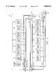
- FIG. 3illustrates a block diagram of a multiservice switch for a telecommunications network having an extended bus, indicated generally at 50, constructed according to the teachings of the present invention.
- Multi-service switch 50forms a cluster comprising one to four chassis each having a 12 slot shelf as shown in FIG. 2.
- An expanded clusterconsists of two or more chassis linked together through an extended bus to provide from twelve to forty-eight chassis slots for interface modules.
- Multi-service switch 50comprises a bus control 52 for Bus A and a bus control 54 for Bus B.
- Bus Ais extended by bus extension 62 and bus extension 64 and is bridged by bus bridge 68 as shown.
- Bus Bis extended by bus extension 56 and bus extension 58 and is bridged by bus bridge 60 as shown.
- a system administration module 70is coupled to both Bus A and Bus B and is connected to three external system management ports: Ethernet, Modem, and Async.
- Multi-service switch 50also comprises a number of interface modules 72 1 through 72 n .
- These interface modules 72 1 through 72 ninterface between telecommunications entities and Bus A and Bus B.
- Interface modules 72 1 through 72 nsupport either isochronous services, asynchronous services, or both.
- Each interface module 72 1 through 72 nis connected to both Bus A and Bus B and operates identically as described with reference to interface modules 28 1 through 28 n . Of FIG. 1.
- multi-service switch 50operates to control communications between a number of telecommunications entities.
- the operation of multi-service switch 50is the same as multi-service switch 10 described with respect to FIG. 1, except for the bus extensions 56, 58, 62 and 64.
- Bus extensions 56, 58, 62 and 64operate to extend control, timing and data on Bus A and Bus B on one chassis to subsequent portions of Bus A and Bus B on the adjacent chassis.
- Bus control 52 and 54control the initial timing for data.
- bus extensions 56 and 62 in the first chassispass the data on to bus extension 58 and bus extension 64 in the second chassis.
- Bus extensions 58 and 64in turn pass ingress data on to extended buses A and B and to bus bridges 60 and 68.
- Bus bridges 60 and 68then return the egress data back to bus extensions 58 and 64 by means of the bus egress portions.
- Bus extensions 58 and 64pass the egress data from the second chassis on to bus extensions 56 and 62, and bus extensions 56 and 62 pass the egress data back to bus control 52 and bus control 54 via the bus egress portions of the first chassis.
- Multi-service switch 50operates otherwise as described with reference to multi-service switch 10. In this manner, the multi-service switch architecture of the present invention can be extended to service a large number of interface modules by using bus extenders to modularly interconnect additional redundant bus segments.
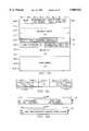
- FIG. 4illustrates a block diagram of one typical telecommunications environment utilizing multi-service switches for telecommunications networks constructed according to the teachings of the present invention.
- a premises network access switch 80is coupled to an edge services distribution network switch 82 by a copper or optical bus 84.
- Premises network access switch 80receives and transmits voice telecommunications information 86, data telecommunications information 88, video telecommunications information 90 and local area network (LAN) telecommunications information 92.
- the line between service provider and user entityis indicated by Service Provider Demarcation line 94.
- Users A through Chave shared access to the telecommunications information switched by premises network access switch 80.
- Edge services distribution network switch 82receives DS1-DS3 circuit or packet information via lines 96 and transfers it to the telecommunications network at the point of presence (POP) indicated by line 98.
- Edge services distribution network switch 82communicates with public switched telephone networks (PSTN) 100, private leased line networks 102, asynchronous transfer mode (ATM) networks 104, and frame relay networks 106.
- PSTNpublic switched telephone networks
- ATMasynchronous transfer mode
- Asynchronous transfer mode backbone networks 104will eventually be constructed with large ATM broadband switches 105 located in the center of the network.
- Edge services distribution network switches 82will also communicate with the existing public circuit switched telephone network 100 and private leased line network 102 via DS1/DS3 lines 108.
- Edge services distribution network switch 82communicates with asynchronous transfer mode backbone networks 104 via ATM OC3/OC12 lines 110 and communicate with existing frame relay backbone networks 106 via frame relay DS1/DS3 lines 112.
- the telecommunications environment shown in FIG. 4operates to allow multiple independent User entities A through C at a premises to transmit and receive telecommunications services to communicate with other user entities at the premises and to communicate with outside entities through switching provided by a common shared premises network access switch 80, access link 84, and edge services distribution network switch 82.
- User entities A, B and Ccommunicate with one another on premises using voice, data, video and local area network telecommunications information services.
- Premises network access switch 80operates to allow users to communicate with one another.
- Premises network access switch 80also communicates via optical line 84 with an edge services distribution network switch 82.
- Edge services distribution network switch 82operates to allow communication with outside entities. Possible outside destinations and sources are those shown in FIG. 4.
- Premises network access switch 80 and edge services distribution network switch 82may utilize multi-service switches for telecommunications networks constructed according to the teachings of the present invention to implement switching of telecommunications services.
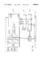
- FIG. 5aillustrates a protocol stack of three bus overlays on a physical slotted bus operating in accordance with the teachings of the present invention.
- a slotted bus (SB) physical (PHY) layer 120models the physical slotted buses of the multi-service switch of the present invention.
- the SB PHY layerimplements the actual transfer of data, both asynchronous and isochronous, to and from the time slots of the slotted buses.
- a packet bus overlay (PBO) layer 122, a narrowband bus overlay (NBO) layer 124, and a wideband bus overlay (WBO) layer 126model three unique access protocols for using the physical transport services provided by the slotted bus physical layer 120 of the multi-service switch of the present invention for three different classification of services.
- the asynchronous transfer mode (ATM) layer 128 and other packet protocols 130model protocol layers using the PBO layer through appropriate service access points (SAP) for providing asynchronous transfer mode communications and other packet-based data communications.
- SAPservice access points
- Packet bus overlay layer 122models the packet bus overlay access protocol of the multi-service switch of the present invention and implements the set of services used by the asynchronous transfer mode layer 128 or by other packet protocols 130 supported by the multi-service switch of the present invention.
- the PBO layer 122allows the exchange of fixed-length packets across the slotted buses of the multi-service switch as a connectionless datagram service.
- Packet bus overlay layer 122is optimized to provide efficient transport services for 53 octet cell payloads (e.g., ATM cells) amongst multiple interface modules residing throughout a multi-service switch chassis or cluster of chassis.
- the packet bus overlay 122is used to implement all asynchronous packet-based services including cell-based and frame-based services supported by the multi-service switch of the present invention.
- the slotted bus physical layer 120supports a narrowband bus overlay 124 and a wideband bus overlay 126.
- the slotted bus physical layer 120is configurable to maintain a plurality of bus overlays. Each bus overlay is associated with one of a plurality of unique data formats supporting a plurality of telecommunications services. As shown in FIG. 5a, slotted bus physical layer 120 supports packet bus overlay layer 122 for asynchronous communication services, narrowband bus overlay layer 124 for narrowband isochronous communication services, and wideband bus overlay layer 126 for wideband isochronous communication services. This operation creates three virtual buses operating independently on one physical bus.
- FIG. 5billustrates allocation of bus time slots between three bus overlays according to the teachings of the present invention.
- FIG. 5billustrates a number of bus time slots where the time slot on the left comes sooner in time than the time slots on the right.
- the bus time slotsmove along the bus from right to left carrying data relating to telecommunications information.
- Time slots 132are allocated to an isochronous wideband bus overlay and as such, occur with periodicity of 125 microseconds.
- the slots composing the wideband, narrowband overlayare selected from any slots currently available for asynchronous traffic, even if they are not evenly spaced in the 125 microsecond frame.
- Each slot of the plurality of slots comprising an isochronous (narrowband, wideband) overlayrepeat with periodicity of 125 microseconds, but the time relationship between slots of the same overlay is unconstrained.
- time slots 134are allocated to a narrowband bus overlay, and as such, their periodicity is 125 microseconds, although the time lapse between arrivals of a time slot 134 may not be constant.
- Time slots 136are allocated to an asynchronous packet bus overlay and occupy the remainder of the bus traffic. Thus, all three overlays exist simultaneously and independently of one another by allocation to separate time slots.
- a multi-service switch for a telecommunications network constructed according to the teachings of the present inventionis operable to allocate dynamically the plurality of time slots on the slotted bus between bus overlays without a disruption of data transmission. For example, time slots allocated to isochronous data and asynchronous data according to a particular mapping can be re-allocated to a different mapping without disrupting transmission of the remaining traffic.
- FIG. 6aillustrates an asynchronous packet bus overlay datagram format constructed according to the teachings of the present invention.
- the datagram formatincludes an internal packet bus overlay (PBO) datagram header 140 and a packet bus overlay (PBO) datagram payload 142.
- the datagram formatincludes sixty-four octets where each octet is eight bits of data as shown.
- Internal packet bus overlay datagram header 140consumes the first eleven octets, octet 0 through octet 10.
- Packet bus overlay datagram payload 142consumes the last fifty-three octets, octet 11 through octet 63.
- the packet bus overlayoperates to provide a connectionless datagram transfer service between packet bus overlay addressable entities through a multi-service switch constructed according to the teachings of the present inventions.
- a packet bus overlay datagramdescribes a sixty-four octet packet composed of eleven octets of reserved overhead, along with a fifty-three octet datagram payload optimized to carry an asynchronous transfer mode cell, as illustrated in FIG. 6a.
- Addressing and routing control informationis included in datagram header 140 to allow the packet bus overlay datagram service to be extended throughout a single cluster or multi-cluster switching system.
- a multi-cluster switching systemconsists of multiple multi-service switch clusters interconnected via the expansion mechanism of FIG. 3.
- a multi-cluster switching systemconsists of multiple clusters interconnected via a self-routing switching fabric.
- Such an asynchronous transfer mode switching fabricis disclosed in U.S. patent application Ser. No. 08/228,598, now U.S. Pat. No. 5,537,400, entitled "Buffered Crosspoint Matrix for an Asynchronous Transfer Mode Switch and Method of Operation" assigned to the assignee of the present application, the disclosure of which is incorporated herein by reference.
- FIG. 6billustrates a packet bus overlay datagram header format.
- the packet bus overlay datagram header formatincludes 11 octets, octet 0 through octet 10, each comprising 8 bits as shown.
- a first octet 144includes the payload type, source bus, expedite message indicator and class of service level/expedite message type information. The next three octets hold the destination address 146 for the datagram.
- a fifth octet 148holds a stage 2 self-routing tag and the first two bits of a stage 3 self-routing tag.
- a sixth octet 150holds the last 4 bits of the stage 3 self-routing tag, and indications as to whether routing is to a local or external destination, and a selection of which expansion switching element and destination bus to utilize.
- the seventh and eighth octetshold a weighted age 152 (i.e., the cumulative age of the datagram within the system, weighted by a factor), and the ninth through eleventh octets hold the source address 154 of the associated datagram.
- the packet bus overlay datagram headercontains all of the internal overhead information required to support full connectionless bearer service of datagrams throughout a multi-service switch system.
- the headerincludes routing information for both point to point and point to multi-point delivery service, quality of service descriptors, cumulative weighted age, and payload type descriptors.
- FIG. 6billustrates these various fields and their location in the packet bus overlay datagram header.
- the packet bus overlayprovides the fundamental packet-based transport services which asynchronous interface modules of the multi-service switch of the present invention utilize to provide standards based services and other asynchronous services.
- the packet bus overlay serviceencompasses many of the sophisticated features required by standard based packet services including support for multiple classifications of various quality of service (QoS), and elaborate traffic management, resource management and control mechanisms.
- QoSquality of service
- the packet bus overlay of the present inventionsupports frame-based services as well as cell-based services.
- Frame-based servicesare those services that use packets of variable length as the basic unit of data exchange. Examples of frame-based services are frame relay networks, and local area network (LAN) native protocols.
- Cell-based servicessuch as asynchronous transfer mode services, are those that use a small packet of fixed-size referred to as a cell.
- the packet bus overlaysupports additional internal management threads that may use high priority in-band channels grafted in the asynchronous portion of the slotted buses. Both cell-based and frame-based services make use of the common PBO datagram format.
- asynchronous packet bus overlay datagramsare formatted as eleven octets of internal overhead and fifty-three octets of payload as illustrated in FIG. 6a.
- the internal datagram overheadcontains information required to support full connectionless bearer service for datagrams throughout the system.
- the payload of a packet bus overlay datagram carrying an asynchronous transfer mode cellis organized in similar fashion as a fifty-three octet asynchronous transfer mode cell.
- the first five octets of the 53 octet cellcontain both asynchronous transfer mode layer protocol control information as well as connection identifiers.
- 6cillustrates the format of the five octet header for the asynchronous transfer mode cell internal to the multi-service switch 10.
- the five octet headercontains an internal connection number and undisturbed VCI and PTI/CLP fields.
- the remaining forty-eight octetscarry the asynchronous transfer mode cell payload. Because of the mapping of the datagram format of the present invention, minimal processing of asynchronous transfer mode cell traffic is required.
- Asynchronous transfer mode cell-based trafficis supported transparently without a need for further adaption to the asynchronous time slots.
- All frame-based trafficis mapped to asynchronous transfer mode cells using a common adaption layer, namely AAL5, as a generic frame adaption mechanism.
- Framesare delimited, padded as required, segmented and inserted into the forty-eight octet payload of one or more asynchronous transfer mode cells at the ingress portion of the slotted bus.
- the associated asynchronous transfer mode cell header of FIG. 6cis appended to each asynchronous transfer mode payload to compose a complete asynchronous transfer mode cell that is in turn mapped as payload into a packet bus overlay datagram according to the teachings of the present invention.
- the packet bus overlayallows implementation of statistical multiplexing and switching of a variety of packet services in concurrent fashion. Any fraction of the asynchronous bandwidth capacity of the slotted buses can be assigned to each service such as frame relay, cell relay, or SMDS. Encapsulation of upper level protocols into any of wide area network transfer protocols is also supported. Protocol conversions between transfer protocols, such as frame relay to cell relay, and 802.3 to cell relay, are supported by the datagram bearer services of the packet bus overlay according to the teachings of the present invention.
- Packet bus overlay addressesare used by the multi-service switch packet bus overlay to identify the originating and terminating end point entities of a packet bus overlay layer communication. These packet bus overlay entity addresses are assigned to each packet bus overlay layer entity of the multi-service switch system of the present invention as the need arises.
- Packet bus overlay addresses that identify the destination end point or end points where a datagram is to be deliveredare carried in the destination address field of the packet bus overlay datagram header. Addresses that identify the source end point originating the datagram are carried in the source address field of the datagram header.
- a packet bus overlay layer entity addressis one of two types: individual or group.
- FIG. 6dillustrates the format of the destination address field for both an individual and group address type.
- Individual addresses 161are composed of three fields as illustrated in FIG. 6d. The first is a two bit field, called the Individual Address Indicator, which is set to the value ⁇ to indicate that the format is an individual address format. The remaining 22 bits are divided into two fields: a cluster number/stage 1 self-routing tag, and a local cluster PBO-SAP address.
- the cluster number/stage 1 self-routing tag fieldserves a dual purpose. In a multi-service switch composed of multiple clusters of chassis 50, the cluster number field identifies one from a plurality of clusters as the destination of the datagram.
- the cluster number/stage 1 self-routing fieldcontains the self-routing tag for the first stage of the self-routing matrix, which coincides with the number of the cluster of chassis 50 connected to the output port of the self-routing matrix.
- the Local Cluster PBO-SAP address fieldcontains the address of the destination interface module 72 1 to 72 n (and port inside the module if more than one port per module) in the destination cluster of chassis 50.
- the Group Address format 163 in FIG. 6dis made of two fields.
- the firstis a two bit Individual Address Indicator field set to not-zero (i.e., 01, 10, or 11) to indicate that the rest of the destination address contains a group address/multicast connection number.
- the second fieldis the group address/multicast connection number itself, which is an unstructured 22 bit address. When combined with the first two bit codepoints 01, 10 and 11, the group address/multicast connection number field can contain in excess of 12 million different addresses.
- An individual addressis assigned to a single entity of the system when a packet bus overlay entity is configured or attached to the system.
- An individual addressthus uniquely identifies a single end point in the system as a potential source or destination of a packet bus overlay datagram. Therefore, individual addresses may be used as both source and destination addresses in packet bus overlay point to point datagrams.
- a group addressmay be assigned to one or more entities in the system.
- a group addressidentifies one or more packet bus overlay entities as potential recipients of the same datagram which is then referred to as a multi-cast datagram from one same source entity.
- Group addressesare only utilized as destination addresses. Unlike an individual address, a group address may be assigned to a group of entities for the duration of one connection only.
- a unique group addressmay be assigned to support a single multi-cast connection provided by a packet bus overlay upper layer entity 128 or 130 in FIG. 5a. When a group address is assigned to a group of entities for the duration of one connection, the group address is referred to as a multi-cast connection number (MCN).
- MCNmulti-cast connection number
- multi-cast connection numbers in place of generic group addressescan yield significant simplification in the administration of the group address number space and yield even further savings in the implementation requirements of the packet bus overlay upper layer entity, such as the asynchronous transfer mode layer user 128 in FIG. 5a, in providing multi-cast connection oriented services.
- the packet bus overlaysupports a number of different quality of service (QoS) classes, also referred to as classes of service (CoS).
- QoSquality of service
- CoSclasses of service
- two attributesdefine a particular class of service. These attributes are the switching delay priority and the packet loss probability. Different combinations of values of those two attributes create multiple CoS levels.
- the overhead assigned to each datagram of the present inventioncan support multiple class of service levels. Four levels are discussed herein for illustrative purposes only.
- the packet bus overlay layerensures a distinct service separation between the supported classes of service. This means that the packet bus overlay layer ensures that the two measurable goals of switching delay and packet loss probability are maintained for each of the four classes of service of this embodiment.
- This separation of classesis independent of the mix of traffic of different classes of service passing through the packet bus overlay.
- the packet bus overlay layerdiscriminates amongst datagrams based on each datagram's associated class of service and acts accordingly. This discrimination requires some arbitration of the asynchronous requests for time slots on the slotted bus.
- One arbitration schemewhich utilizes switching delay priority as an attribute to discriminate amongst multiple requests is described in U.S. patent application Ser. No. 08/228,598, now U.S. Pat. No. 5,537,400, entitled "A Bus Arbitration Method for Telecommunications Switching" which has been previously incorporated herein by reference.
- the packet bus overlay of the present inventionsupports an additional class of service referred to as an expedite class of service which is not subjected to the same normal arbitration as the other classes of service and which is not measured in terms of its switching delay or packet loss characteristics.
- the expedite class of serviceis used for intersystem management communications of an urgent nature, such as a failure or congestion notifications.
- Expedite class of service datagramsare handled in a strict first come first serve order amongst themselves in this embodiment of the present invention. Expedite class of service datagrams do not compete directly with datagrams of the other four normal classes of service for access to the buses.
- the packet bus overlay layerprovides entities with packet bus overlay bearer services consisting of both point to point (unicast) and point to multi-point (multicast) modes of data transfer.
- a unicast datagramis a datagram that contains a datagram header containing an individual destination address 161 in FIG. 6d associated with a single peer packet bus overlay entity.
- a multi-cast datagramis a datagram that contains a header containing a group destination address 163 of FIG. 6d associated with one or more peer packet bus overlay entities.
- Multi-cast packet bus overlay datagram serviceis identical to unicast datagram service with the exception that each multi-cast datagram, obtained from a single source, is potentially copied from a slot of the asynchronous bus by multiple destination peer packet bus overlay entities, all of which are associated with the common group address.
- FIG. 6eillustrates a block diagram of entity to entity unicast communication.
- a first packet bus overlay layer entity 155a and a second packet bus overlay layer entity 155bcommunicate via an ingress bus 157 and an egress bus 158.
- Packet bus overlay layer entity 155a and packet bus overlay layer 155bcommunicate via datagrams 159.
- the packet bus overlay unicast communicationoccurs between two peer packet bus overlay layer entities 155a and 155b within a multi-service switch system of the present invention.
- Unicast datagrams 159are utilized for point to point transport of data having a number of different class of service levels between the two communicating peer entities 155a and 155b. As shown in the embodiment of FIG. 6e, there are four different class of service levels as indicated by the four queues in each of the ingress and egress queuing systems 156a-d in packet bus overlay layer entity 155a and packet bus overlay layer entity 155b.
- Datagrams 159a that originate after a request from a user of the packet bus overlay layer entity 155aare placed in the ingress queuing system 156a of packet bus overlay layer entity 155a while awaiting access to the underlying physical bus layer.
- Unicast datagrams 159bwait for granted access to an asynchronous time slot on ingress bus 157 for transmission throughout the multi-service switch system.
- the class of service level associated with datagrams 159bdetermines the priority that the packet bus overlay layer entity 155a requests from the arbiter and is granted for access to ingress bus 157.
- the destination address of every datagram broadcasted via the asynchronous time slots on the egress bus 158is examined one by one by peer packet bus overlay layer entities 155a and 155b.
- packet bus overlay layer entity 155brecognizes a destination address matching one of its assigned individual addresses
- packet bus overlay layer entity 155bcreates a copy of the datagram 159c and places it in the egress queuing system 156d of packet bus overlay layer entity 155b according to the associated class of service level.
- the datagram 159cthen awaits delivery to the upper layer entity.
- Unicast datagrams 159are maintained in separate subqueues in all encountered queuing systems 156a-d according to their class of service in order to provide the separation of quality of service levels associated with each class of service.
- Asynchronous time slotsare used both for local switching of packet services utilizing packet bus overlay datagrams between entities of the same slotted bus, entities in the same chassis or cluster, and for external switching between entities in different clusters.
- a multi-service switch constructed according to the teachings of the present inventionsupports multiple communications services with different quality of service requirements for switching delay and packet loss.
- Switching delayis more critical to some packet services than to others.
- Fast switching timesare more important for example to video connections than to bulk data connections; thus video connections should be switched more expeditiously than bulk data connections.
- Data of time constrained communications servicesshould be preferred over less time constrained communications services even when the latter have spent less time in the system.
- a priority scheme capable of discriminating between the time-related needs of the various communications servicesgreatly reduces the switching delays and delay variations of time-sensitive communications services such as video and voice communications.
- the switching delay component of the quality of serviceis maintained by the packet bus overlay layer using a datagram timestamping procedure.
- the timestamping procedureutilizes the weighted age field of the datagram header illustrated in FIG. 6b.
- the timestamping processrecords the time of arrival of each datagram into a packet bus overlay layer queuing system.
- the datagramsare timestamped when they come into the system.
- the time stampis a two's complement number stored locally associated with the datagram, calculated as the difference between the value of a time of arrival counter and the value in the weighted age field of the datagram header.
- the difference between the stored timestamp and the datagram's time of departureis calculated.
- the difference between these two valuesis the actual time spent by the datagram in the queue plus the age of the datagram when it arrived to the queue, in other words, the updated datagram's age.
- the aging processis weighted.
- the ages of datagrams of different classesincrease at different rates, representing the varying urgency of their switching.
- a configurable parameteris associated with every class of service level and is used as a weighting factor to weight the age values calculated for datagrams of each class of service level.
- the age of a datagramis multiplied by the weighting factor to produce the weighted age of the datagram.
- This weighted age valueis then used to allow priorities and cumulative delay to be considered in the service discipline as a single figure of merit. When multiple datagrams of different switching delay priority compete for the same output, the one with the largest age value is selected next.
- each class of serviceis equipped with a time counter that increments by one weight factor (WF) each switching interval.
- WFweight factor
- the WF value of each classis different and programmable.
- High priority delay classes of serviceare programmed with a higher WF value than low priority classes.
- the time counters of each classdo not have to be synchronized. Assume that at the time of arrival of a datagram to a queue, the time counter associated with the datagram CoS contains the value T.sub. ⁇ , and that the datagram's weighted age is Age.sub. ⁇ .
- the value of TSis stored with the datagram.
- the time counter valueis T 1 , where T 1 >T.sub. ⁇ .
- the cumulative weighted age of a datagramequals the cumulative time spent in all the queues up to the present time multiplied by the associated weighting factor.
- This valueis placed in the header of the datagram and carried between queues of the multi-service switch system of the present invention.
- the weighted ageis represented as an integer number of bus time slot intervals. It is a system-wide variable, thus its value increases cumulatively when a datagram passes from one queue to the next queue in the switching system. The weighted age of a datagram is therefore updated and carried between queuing systems in the weighted age field of the datagram header.
- FIG. 7illustrates congestion in an output buffer at the egress of the slotted bus 246, caused by simultaneously occurring frame bursts from different sources destined for the same output destination.
- a first local area network (LAN) 240, a second local area network (LAN) 242, and a third local area network (LAN) 244are coupled to slotted bus 246.
- Egress packets 248 exiting the slotted bus 246are provided to an output buffer 250.
- Output buffer 250communicates to Ti network facility block 252.
- FIG. 7Congestion due to transmission rate mismatches and the subsequent loss of data is a problem in the scenario illustrated in FIG. 7.
- multiple local area networks 240, 242 and 244each supplying bursty traffic at a high peak rate, are connected to a single wide area T1 network facility block 252 of lower rate than the aggregate of the rates of local area networks 240, 242 and 244.
- the problemis compounded by the fact that frames are segmented into multiple time slots and transmitted across slotted bus 246 in discontinuous form shown as segmented packets 248.
- each contributing sourcetransmits only one frame at a time. Thus, interleaving of frames at the source does not occur. Interleaving of frames at the destination buffer 250, however, does occur when two or more sources, such as local area networks 240, 242, and 244, transmit simultaneously towards the same destination.
- Losseswill occur if a source, such as a local area network, sends a frame across slotted bus 246 towards output buffer 250 when no buffer resources are available for the reassembly and posterior transmission of the frame. Losses may be reduced and reliability in the transfer of data across the bus may be improved by implementing some mechanism for controlling the data flow between sources and destinations. It is clear, for instance, that a T3 network facility loaded with bursty data could easily swamp a T1 network facility interface even if the average data rate is below 1.5 Mbps unless a throttling mechanism is in place.
- Two possible internal flow techniquesmay be used to alleviate this problem: (a) an addition of a sufficiently larger number of frame buffers in the output queue to accommodate the maximum burst sizes, or (b) a backpressure mechanism employing a backoff protocol whereby a congested egress output buffer 250 could communicate to its congesting ingress sources 240, 242, and 244 to temporarily halt or backoff on the amount of traffic being transmitted towards the congested output buffer 250.
- FIG. 8aillustrates a block diagram of a backoff protocol used in accordance with the teachings of the present invention.
- a packet bus overlay (PBO) source 200communicates with a packet bus overlay (PBO) destination 202.
- Packet bus overlay source 200includes an egress block 204 and an ingress block 206.
- packet bus overlay destination 202includes an egress block 208 and an ingress block 210.
- Multiple packet bus overlay sourcesmay contribute at any given time to the congestion experienced by packet bus overlay destination 202.
- the backoff procedure initiated by destination 202is repeated for other congesting sources.
- a feedback or backoff procedureis initiated by packet bus overlay destination 202.
- the backoff procedureinvolves the exchange of explicit backoff messages from the congested packet bus overlay destination 202 to the congesting packet bus overlay source 200 and any other sources contributing to the congestion at destination 202.
- Backoff messagesare transmitted using the expedite service over the system bus from congested packet bus overlay destination 202 to congesting packet bus overlay source 200.
- the backoff messagerequests the ceasing of the transmission of datagrams by the congesting packet bus overlay source 200 for a pre-determined period of time.
- the backoff protocolaffects only datagrams of the enabled backoff classes, for example, datagrams of specific classes of service. Transmission of datagrams of disabled classes are not affected by backoff periods. Conversely, disabled classes of service at the congested destination 202 will not invoke backoff messages.
- a level of congestion above a specified backpressure leveltriggers the start of the backoff protocol.
- the scope of the backoff procedureincludes datagrams of the enabled classes of service only. As stated above, disabled classes of service do not participate in the backoff protocol.
- Egress block 208 of congested packet bus overlay destination 202upon reception of a user datagram 212 while egress block 208 is in this congested state.
- Egress block 208 of packet bus overlay destination 202upon reception of datagram 212 of a backoff enabled class of service, issues a generate backoff signal 213 to its ingress block 210 as shown in FIG. 8a.
- the generate backoff signal 213passes to ingress block 210 the following parameters: the address of the congesting packet bus overlay entity (address #1 in this example), obtained from the source address field of the incoming datagram, the address of the local entity obtained from the destination address field of the incoming datagram (address #2 in this example), and the bus selection from the source bus selector bit 5 octet ⁇ in FIG. 6b of the incoming datagram.
- ingress block 210 of packet bus overlay destination 202Upon receipt of the generate backoff signal 213 from egress block 208, ingress block 210 of packet bus overlay destination 202 generates a backoff message 214.
- FIG. 8billustrates a backoff message format according to the teachings of the present invention.
- the first octet 220holds the payload type field, source bus selector A or B, expedite message indicator, and expedite message type which is 1110 meaning a backoff message.
- the next three octetshold the destination address 222.
- the next four octetscomprise a don't care region 224 followed by the source address 226.
- a reserved octet 228follows the source address 226.
- the maximum backoff time 230is held in the 13th to 16th octets and is followed by a reserved region 232.
- the destination address field 222contains the address of the congesting packet bus overlay source, and the source address field 226 contains the address of the congested packet bus overlay destination.
- the maximum backoff time 230is a 32 bit unsigned positive integer number representing the maximum number of system bus cycles that any congesting packet bus overlay entity has to backoff upon receipt of the backoff message. The actual backoff time is derived randomly from the maximum backoff time by each receiving packet bus overlay entity according to the method illustrated in FIG. 8c.
- the response to the receipt of backoff message 214 at packet bus overlay source 200is to stop sending PBO datagrams of the enabled classes of service for some period of time.
- Egress block 204 of packet bus overlay source 200upon reception of a backoff message 214, issues a received backoff signal 215 towards ingress block 206.
- the received backoff signal 215passes to ingress block 206 of packet bus overlay source 200 the following parameters: a maximum backoff time and, optionally, the address of packet bus overlay destination 202 being congested, obtained from the source address field of backoff message 214.
- ingress block 206 of packet bus overlay source 200calculates a random actual backoff time according to the method illustrated in FIG. 8c.
- Ingress block 206 of packet bus overlay source 200does not forward any datagrams of the backoff-enabled classes of service for a duration of time equal to the calculated backoff time. In the event of receiving subsequent backoff messages while still in the backoff mode, a new calculation of the backoff time and a new backoff time period is started. If an address is passed with the received backoff signal 215, the packet bus overlay source 200 calculates a random backoff time and starts the backoff time period, but optimally may continue normal transfer of requests from enabled class of service subqueues until the destination address of the datagram at the head of a subqueue matches the address passed with the backoff signal. At that time, transfers of requests from that subqueue are suspended until the end of the backoff time period.
- the ingress side 206 of packet bus overlay source 200resumes normal transfer of datagrams at the end of the backoff time period whether the end is caused by the expiration of the period or by a forced termination resulting from a state of congestion being decided at the ingress block 206.
- This latter forced termination of the backoff period at the ingress side of the congesting sourcesprevents the backoff protocol from causing packet loss at the ingress side of the multiservice switch.
- FIG. 8cillustrates probability density functions of backoff times according to one embodiment of the present invention.
- the packet bus overlay layer management entityconfigures which one of the two is utilized for each congesting source 200.
- the ingress blockderives an actual backoff time by the division of the maximum backoff time by a power of two, namely 2 n , where n is a random value between 0 and N obtained by the ingress block from a random number generator.
- FIG. 8cillustrates the probability density function of backoff times derived in this manner as function A.
- the ingress blockderives an actual backoff time by subtracting the division of the maximum backoff time by the random power of 2, 2 n , from the maximum backoff time. Therefore, the probability density function is illustrated in FIG. 8c as function B where n is a random value between 0 and N obtained by the ingress block from a random number generator.
- the ingress block of packet bus overlay entitiesforces a termination of any backoff period in progress when a severe congestion threshold is reached at the ingress side 206.
- the packet bus overlay entityignores the backoff enable/disable configuration status of the ingress block 206, thus forcing the termination of any backoff time period in progress.
- the normal backoff enable/disable statusis reinstated when the ingress queues return to a non-congested state.
- the multiservice switch 10is equipped with extensive selective datagram discard procedures. These selective datagram discard procedures are executed by the packet bus overlay entities 155 managing the buffers that make the ingress block and egress block queuing systems 156. During periods of severe congestion, the queues in a packet bus overlay entity discard datagrams of selected classes of service in a controlled manner that favors discarding of datagrams of low priority classes of service over high priority classes. A variety of discard methods are available to the packet bus overlay entity. A first method is the forcible dequeuing of datagrams of selected classes of services from the head of the subqueues, freeing occupied buffers for use by arriving datagrams. The freed buffers are made immediately available for queuing of new packets of the same or higher loss priority.
- a second methodis discarding datagrams of selected classes of service arriving at the queuing system rather than enqueuing them.
- a thirdis to discard datagrams of asynchronous transfer mode connections of selected classes of service if the asynchronous transfer mode cell they are carrying has the CLP bit set to a one.
- the final methodis to discard incoming datagrams of any class of service if no more buffers are available.
- the selective packet bus overlay datagram discard proceduresare common to both the ingress and the egress blocks of packet bus overlay entities 155a and 155b, respectively.
- FIG. 9aillustrates a stack diagram of a wideband bus overlay according to the teachings of the present invention.
- Wideband servicesare defined as isochronous connections requiring T1/E1 bandwidth and greater.
- a SONET/SDH time division multiplexing (TDM) scheme overlayed onto isochronous time slots exclusively assigned to the wide band bus overlaymay be used according to the present invention.
- the wideband bus overlaysupports STS-1, TU-3, VT1.5 and VT2 multiplexing and crossconnect. This SONET/SDH format allows for transparent multiplexing and crossconnect of plesiochronous signals including T1, E1, T3 and E3 signals.
- a physical ingress bus 160is overlaid by a wideband circuit bus overlay (WBO) 162.
- WBOwideband circuit bus overlay
- This wideband bus overlaysupports three basic data structures which in turn support five other data structures as shown in stacks 164.
- the three basic data structuresare STS-1 SPE+PTR, VT1.5 and V2 as shown. Support of these three basic structures enables the multi-service switch of the present invention to process all North American and European PDH datatypes, with the exception of E4. All isochronous wideband interfaces are adaptable and map payloads into these structures for access to the isochronous wideband bus overlay 168.
- FIG. 9ashows that T3/E3 and TU-3 formats are adapted into the STS-1/SPE format. Similarly T1 is adapted into the VT1.5 format and E1 is adapted into the VT2 format.
- Egress bus 166is overlaid by wideband circuit bus overlay 168.
- Wideband bus overlay 162 and wideband bus overlay 168are bridged and both support the three basic data formats STS-1 SPE+PTR, VT1.5 and VT2.
- Wideband circuit bus overlay 168supports the basic data structures and other data formats as shown in stacks 170.
- the wideband circuit bus overlay of the present inventionsupports Plesiochronous Digital Hierarchy (PDH), Synchronous Digital Hierarchy (SDH) and SONET datatypes including T1, E1, E3, asynchronous T3, STS-1, OC-3 and STM-1.
- PDHPlesiochronous Digital Hierarchy
- SDHSynchronous Digital Hierarchy
- SONET datatypesincluding T1, E1, E3, asynchronous T3, STS-1, OC-3 and STM-1.
- the amount of bandwidth allocated to the wideband bus overlayis variable. Bandwidth requirements range from 27 octets, which is less than one slot, for a VT1.5 format to 786 octets, which is over 12 time slots, for an STS-1 SPE plus pointer (STS-1 SPE+PTR) format. Efficient use of bandwidth is maintained by treating isochronous bandwidth reserved for wideband formats as one continuous resource pool, addressable at the octet level. In this way, VTn (VT1.5 or VT2) circuits are allocated across time slot boundaries. For STS-1 and TU-3 circuits, the system of the present invention allocates an integer number of time slots per circuit. An STS-1 requires 786 bytes and is assigned 13 slots or 832 bytes.
- This reservation methodallows for quick release of bandwidth for asynchronous services when STS-1/TU-3 services are removed.
- Data from a T1/E1 interfaceis placed onto the ingress bus in a VT format.
- Each interfaceis provided with an egress STS-1/TU-3 pointer processor and a VT mapper/demapper which performs the translation between T1/E1 and VT1.5/VT2 respectively.
- Data from a SONET/SDH or T3/E3 interfaceis placed onto the ingress bus in an STS-1/TU-3 format which includes SPE/VC pointer information from plesiochronous synchronization.
- Each interfaceis programmed with an egress time slot interchange (TSI) which determines which VT's are to be sourced from the egress bus, and in what order the VT's are to be mapped into an outgoing STS-1/TU-3 or T3/E3.
- TTIegress time slot interchange
- FIG. 9billustrates a payload envelope for the wideband bus overlay.
- the Wideband Bus Overlayprovides transparent transport of plesiochronous data streams through implementation of a payload envelope and pointer structure providing octet justification and synchronous payload tracking similar to SONET/SDH structures.
- the octet number 1 to Mrepresents the number and time division order of isochronous octets reserved for a WBO payload envelope.
- the first two octets(H1 and H2) are located at the beginning of the envelope and contain 6 pointer control bits and a 10-bit pointer value from 0 to N used to identify the first octet of a payload frame where location 0 is the first octet of the payload container and location N is the last octet of the payload container.
- the third payload envelope octet location(H3) is used as a place holder for data during a negative justification process. Justification, pointer movements and pointer contents follow rules described in TR-NWT-000253 and CCITT Recommendation G.709 for efficient mapping of SONET/SDH structures.
- the remaining octetsform a container for plesiochronous data.
- This containermay be any size required to encapsulate one 125 ⁇ s frame of plesiochronous data up to 1024 octets.
- the system of the present inventionuses the WBO payload envelope to transport the STS-1 SPE+PTR data format.
- the pointer valueindicates the first octet of path overhead (J1) of the STS-1 SPE.
- FIG. 9cillustrates adaptation of STS-1 Synchronous Payload Envelope (SPE) to a wideband bus overlay format according to the teachings of the present invention.
- SONET/STS-1/SPE format 172is transformed to wideband bus overlay format 174 as shown.
- the illustration of FIG. 9cshows the adaptation of a SONET/STS-1/SPE to the isochronous wideband bus overlay of the present invention.
- each individual STS-LSPE plus H1, H2 and H3 bytes (786 bytes)is output to the ingress bus mapper.
- Bytes H1 and H2contain the pointer value between 0 and 782 that tracks the position of the first byte of the SPE path overhead relative to the first byte following H3.
- H3is used to carry the extra SPE byte in the event of a negative justification.
- SPE pointer processing and justificationare continuous real time processes implemented in hardware.
- the STS-1/SPEsupports mappings including single DS3 or multiple VTG's.
- FIG. 9dillustrates adaptation of TU-3's extracted from a VC-4 structure to a wideband bus overlay format according to the teachings of the present invention.
- each SDH/VC-3 182 extracted from a SDH/VC-4 mapped with TU-3's 180is converted to an STS-1 SPE 184 by adding two columns of fixed stuff as shown.
- each TU-3resembles and STS-1 SPE.
- each TU-3's associated pointer octetsare adjusted to compensate for changes to the payload during the addition of fixed stuff.
- the assembled STS-1 SPE 184 and new pointer octetsare then multiplexed into an STS-1 SPE+PTR 186 structure for transport across the wideband bus overlay.
- An SDH/VC-3is converted to a SONET SPE payload by inserting a stuff column between columns 29 and 30 and a stuff column between columns 57 and 58 as shown in FIG. 9d.
- Crossconnect of E1's/T1's and multiplexing of E1's/T1's to higher order aggregates, M13 or SONET multiplexingmakes use of the wideband bus overlay.
- a T1 interfacing to the wideband bus overlayis adapted to a VT1.5.
- An E1 interfacing to the wideband bus overlayis adapted to a VT2.
- T1's/E1's destined for M13 multiplexers or asynchronous crossconnectuse an asynchronous or bit synchronous VT mapping. This restriction is required to meet DSx jitter requirements.
- T1's/E1's destined for SONET interfacesuse the VT mapping appropriate for the end destination.
- An aggregateis a T3, E3, OC-3 or STM-1. Although the term aggregate implies that these structures contain multiplex T1/E1 streams, these interfaces can be treated as virtual channels with any data content.
- the SONET/SDH aggregatesuse pointers and byte justification at each stage of multiplexing to adapt plesiochronous payloads into synchronous envelopes.
- the SONET/SDH aggregate interface of the present inventionprocesses all pointers associated with SPE, AU-x and TU-3 envelopes to track payload framing from the network as well as perform justification and pointer adjustment to adapt payloads to the network.
- One pointer methodis used for all pointers. Pointer processing and justification are continuous real time processes implemented in hardware.
- a SONET interfacecontains a two byte pointer and one justification byte per STS-1.
- the pointertracks the first byte of the SPE path overhead (J1) and indicates positive or negative justification occurrence.
- a SONET OC-3 interfaceprocesses three independent SPE pointers per direction.
- An SDH/STM-1 aggregatecan contain one AU pointer associated with three justification bytes and up to three TU pointers associated with one justification byte each up to four pointers per direction.
- An AU-4 pointertracks the first VC-4 path overhead byte (J1) and indicates positive or negative justification occurrence. Justification occurs in three byte steps.
- An SDH/STM-1 interface provisioned for AU-4 mappingprocesses one AU-4 pointer per direction to locate the AU-4 path overhead and imbedded TU pointers.
- An SDH/STM-1 mapped for AU-3 operationis the same as a SONET OC-3.
- An SDH interface operating in this modeprocesses a two byte pointer and one justification byte per TU-3.
- the pointertracks the first byte of the TU-3 path overhead (J1) and indicates positive or negative justification occurrence.
- An SDH interface operating in this modeprocesses three independent pointers per direction.
- a TU-3 pointertracks the first VC-3 path overhead byte (J1) and indicates positive or negative justification occurrence. Justification occurs in one byte steps.
- An SDH/STM-1 interface provisioned for TU-3 mappingprocesses three individual TU-3 pointers per direction to frame each VC-3. Some signal conditioning occurs on the tributary interface in order to interface with the slotted bus of the present invention.
- a tributaryis a T1 or E1. T1's are mapped into VT1.5's. E1s are mapped into VT2's.
- a tributary interfaceprovides the mechanism for identifying VT's within the SPE/VC. For each tributary terminated by the interface, the SPE/VC envelope first is identified and the pointer processed to determine the alignment of the SPE/VC. Once the alignment of the SPE/VC is determined, the position of any VT can be calculated with a hierarchial count structure.
- SONET/SDH virtual tributariesuse pointers and byte justification to adapt plesiochronous payloads into synchronous envelopes with a similar Mechanism to that used in the aggregate interface.
- the SONET/SDH tributary interface of the present inventionprocess a single pointer per direction associated with each connected VT to track payload framing from the network as well as perform justification and pointer adjustment to adapt payloads to the network. As discussed above, one pointer algorithm is used for all pointers. VT pointer processing and justification are continuous real time processes implemented in hardware.
- T1 and E1 trunksmust be adapted to a SONET VT format before they can be routed to the system bus.
- Adaptationincludes mapping of Channel Associated Signaling (CAS) into one byte field, sub-frame tagging, pointer processing, and byte or bit justification depending on VT mode: locked, byte synchronous/floating, bit synchronous/floating or asynchronous.
- CASChannel Associated Signaling
- Each tributary VTis managed as a separate logical element on the isochronous wideband bus overlay.
- An elastic bufferis utilized per tributary to absorb waiting time jitter, clock jitter and wander and pointer movements. Since channel alignment is not important for trunk to trunk crossconnect, this buffer may be less than one frame deep assuming that jitter, wander and pointer movements amount to less than one frame of phase jitter peak to peak.
- FIG. 10aillustrates a narrowband bus overlay data structure for isochronous T1 and E1 traffic carrying data and/or uncompressed PCM voice.
- the narrowband bus overlayallows the present invention to support transport of circuit-switched Time-Division-Multiplexed data/voice with a granularity of 64 kbps and minimal delay.
- T1 Narrowband Bus Overlaydata/uncompressed voice
- Incoming T1 signals received by interface modules 28 1 to 28 nare formatted according to the format in FIG. 10a.
- the first octet of the T1 overlay structureincludes four signaling bits Sa, Sb, Sc, and Sd, and a framing bit F.
- the following 24 octetscarry T1 timeslots 1-24 as shown, and can contain a mixture of data and 64 kbps uncompressed voice.
- the signaling bitsare used in conjunction with uncompressed voice traffic carried on some or all of T1 timeslots 1-24, and are typically not used for data traffic.
- the framing bit Fis used only for transparent T1 operation, where the entire T1 frame is placed into the overlay structure intact as received from a T1 link.
- the T1 framing bit from each received frameis placed in the F bit position of the T1 structure. S-Signaling bits are not required, since the original T1 multiframe, imbedded within the framing bits, is preserved.
- the T1 structureis placed within a 64-octet timeslot on the slotted bus that has been designated as an isochronous timeslot as previously described, with up to two overlays per slot. For redundancy, both slotted buses are driven simultaneously with identical information.
- a T1 structuremay be overlaid within an isochronous timeslot such that octet 0 of the T1 structure corresponds with either octet 0 or octet 32 of the bus timeslot. Since the T1 structure is only 25 octets long, octets 25 through 31 and 57 through 63 of the isochronous bus timeslot are unused by the T1 overlay.
- Incoming E1 signals received by interface modules 28 1 to 28 nare formatted according to the E1 structure format of FIG. 10a.
- the first octet of the E1 overlay structurecontains two sets of four signaling bits Sa, Sb, Sc, and Sd. These signaling bits are in the same format as received in timeslot 16 of the E1 link.
- the remaining 31 octetscontain E1 timeslots 0-15 and 17-31.
- the E1 timeslotscan contain a mixture of data and 64 kbps uncompressed voice.
- the signaling bitsare used in conjunction with uncompressed voice traffic carried on some or all of channels 1-15 and 17-31, and are typically not used for data traffic.
- E1 timeslot 0is reserved for framing and E1 alarm information, and is unavailable for transport of 64 kbps voice/data.
- E1 timeslot 0does, however, contain some unused bandwidth which may contain user traffic. For this reason, timeslot ⁇ is placed into the E1 structure as received by the E1 interface module.
- the E1 structureis placed within a 64-octet timeslot on the slotted bus that has been designated as an isochronous timeslot as previously described, with up to two E1 overlays per bus timeslot.
- An E1 structuremay be overlaid within an isochronous bus timeslot such that octet 0 of the E1 structure corresponds with either octet 0 or octet 32 of the bus timeslot. Since the E1 structure is 32 octets long, the structure leaves no unused information within the isochronous bus timeslot.
- each signaling octetcontains signaling information for 1 (T1) or 2(E1) channels.
- the system multiframe structureprovides a method of determining the T1 or E1 timeslot for which each signaling octet is associated.
- the T1 and E1 linkseach contain a multiframe structure, separate from the system multiframe, for the purpose of extracting signaling information from the link.
- the T1 multiframeis either 12(D4 framing) or 24(ESF framing) T1 frames long.
- the E1 multiframeis 16 E1 frames long.
- the least common denominator for these multiframe lengthsis 48 frames, thus a 48-frame system multiframe is utilized to identify signaling information.
- the 48-frame lengthallows for one common system multiframe to support all incoming multiframe lengths, with an integer number of incoming T1/E1 multiframes per system multiframe.
- Received signaling informationis placed in an ingress signaling buffer on the T1 or E1 interface card, and is read out during overlay formatting according to the system multiframe number in which the overlay is to be sent on the slotted bus.
- a system multiframe synchronization signalis generated by the head of bus control 12 and 20, and is bussed to all physical chassis slots. This signal, occurring every 6 msec, is used to synchronize the multiframe channel counters on each isochronous interface card. The channel counters are used to keep track of the current system multiframe channel, making it possible to associate each signaling octet within the T1 or E1 overlays to its corresponding voice channel on an outbound link. For example, referring to FIG.
- signaling information for T1 timeslot 16is read from the signaling buffer and placed in the first byte of the overlay, along with the received framing bit.
- signaling for four D4-framed T1 multiframes, two ESF-framed T1 multiframes, or three E1 multiframesmay be carried.
- FIG. 10billustrates the system multiframe structure for trunks carrying 64 kbps uncompressed voice.
- D4-framed T1 trunksonly two signaling bits (a and b) are supported per channel.
- Each signaling octet within the T1 overlaycarries two sets of signaling bit pairs, received in successive multiframes from the incoming D4 T1 stream.
- system multiframe channel 1contains four signaling bits for a D4-framed T1 link.
- Bits a 1a and b 1acontain the a and b signaling bits received within a T1 multiframe for channel 1 on the T1 link, and bits a 1b and b 1b contain the a and b signaling bits received for channel 1 on the following T1 multiframe.
- each signaling octetcarries signaling received for a particular T1 channel on two successive T1 multiframes.
- four signaling bits(a, b, c, and d) are supported per channel. In this mode, each signaling octet carries signaling received for a particular channel on one ESF T1 multiframe.
- E1 trunkssupport four signaling bits per channel, and these bits are carried in pairs within Timeslot 16 on the E1 link. This structure is preserved within the system multiframe, as shown in FIG. 10b, where each signaling octet in the E1 overlay contains signaling information for two E1 timeslots.
- the E1 multiframe alignment signalwhich determines the beginning of the E1 multiframe and carries alarm information, is also carried within the E1 overlay.
- FIG. 10cillustrates the narrowband bus overlay structure for trunks containing compressed voice.
- FIG. 10dillustrates the number of signaling octets needed for various compression schemes. As shown, the number of signaling octets changes from one to four as the compression type changes from 32 kbps to 8 kbps.
- the compressed signaling overlay for T1provides for carrying four signaling bits per voice channel, while the E1 overlay allows two bits per channel. Note that four signaling bits per voice channel can be supported for E1 by adding more octets to the overlay, but no standard currently exists for transport of more than two signaling bits per channel over E1.
- FIG. 10eillustrates mapping of compressed-channel signaling to the system multiframe according to the teachings of the present invention.
- signaling for timeslot 2 on T1 links, and for timeslots 1 and 2 on E1 linksis carried within the narrowband overlay on isochronous system slots.
- For each timeslot number shown in FIG. 10ethere is associated one to four signaling octets within the overlay, depending on the compression type used.
- Signaling bit mapping for E1 links supporting the CCITT G.761 signaling protocolis also shown in FIG. 8e.
- the G.761 protocolis applicable to 32 kbps voice compression only, and thus takes up one signaling octet in the E1 overlay.
- Bus bandwidthis allocated to narrowband interfaces by reserving 64-octet timeslots on the slotted bus for isochronous traffic.
- Each bus timeslotmay carry data and signaling for up to two T1 or E1 trunks.
- datais received from the attached T1 or E1 link and formatted according to the narrowband overlays previously described.
- the interfaceis programmed with the bus timeslot number that has been allocated for its data, and the received data is placed on the ingress bus within the allocated timeslot for every system frame.
- a timeslot interchange methodis used to allow remapping of information received from the egress bus into the outbound timeslots of the T1 or E1 link.
- This methodallows the egress hardware to be programmed with a cross-connect mapping to determine when to receive data from the egress bus.
- the egress hardwareBy programming the egress hardware with the timeslot number and octet number to receive from the slotted bus for each outbound T1 or E1 timeslot, information from any inbound T1 or E1 timeslot in the system may be transmitted on any outbound T1/E1 timeslot, implementing a fully non-blocking 64 Kbit/second timeslot interchange. Broadcasting of information from one received T1/E1 timeslot to multiple outbound T1/E1 timeslots is accomplished by programming the egress time slot map of multiple interface cards, or multiple T1/E1 timeslots within a single egress interface, to receive the same timeslot from the egress bus.
- a multi-service switch for telecommunications networks constructed according to the teachings of the present inventionprovides a number of advantages.
- One technical advantageis the building of three unique bus overlays on the same physical bus configured to service three different types of telecommunications services.
- a further technical advantageis the ability to change dynamically allocations of time slots on the bus between isochronous and asynchronous services without a disruption of existing traffic on the system.
- a further technical advantage of the present inventionis the transformation of one data format to another data format inside a server module allowing interworking between many different types of telecommunications services within a single service platform.
- Another technical advantage of the present inventionis the unique format for each overlay and independent operation although the overlays share the same bus.
- Another technical advantage of the present inventionis that the multi-service switch for telecommunications network of the present invention allows the transformation of all telecommunications information into one of a plurality of formats which are transmitted on a single physical system bus.
- Another advantage of the present inventionis that the control of all the hardware modules uses the same packet bus overlay as the user information without requiring additional hardware.
- Another advantage of the present inventionis its reliable operation due to the use of redundant buses with automatic switchover after a failure.
Landscapes
- Engineering & Computer Science (AREA)
- Computer Networks & Wireless Communication (AREA)
- Signal Processing (AREA)
- Data Exchanges In Wide-Area Networks (AREA)
- Time-Division Multiplex Systems (AREA)
- Small-Scale Networks (AREA)
Abstract
Description
Claims (7)
Priority Applications (1)
| Application Number | Priority Date | Filing Date | Title |
|---|---|---|---|
| US08/664,994US5809021A (en) | 1994-04-15 | 1996-06-10 | Multi-service switch for a telecommunications network |
Applications Claiming Priority (2)
| Application Number | Priority Date | Filing Date | Title |
|---|---|---|---|
| US08/228,304US5526344A (en) | 1994-04-15 | 1994-04-15 | Multi-service switch for a telecommunications network |
| US08/664,994US5809021A (en) | 1994-04-15 | 1996-06-10 | Multi-service switch for a telecommunications network |
Related Parent Applications (1)
| Application Number | Title | Priority Date | Filing Date |
|---|---|---|---|
| US08/228,304ContinuationUS5526344A (en) | 1994-04-15 | 1994-04-15 | Multi-service switch for a telecommunications network |
Publications (1)
| Publication Number | Publication Date |
|---|---|
| US5809021Atrue US5809021A (en) | 1998-09-15 |
Family
ID=22856616
Family Applications (3)
| Application Number | Title | Priority Date | Filing Date |
|---|---|---|---|
| US08/228,304Expired - LifetimeUS5526344A (en) | 1994-04-15 | 1994-04-15 | Multi-service switch for a telecommunications network |
| US08/356,445Expired - LifetimeUS5526349A (en) | 1994-04-15 | 1994-12-13 | Data formats for telecommunications networks |
| US08/664,994Expired - LifetimeUS5809021A (en) | 1994-04-15 | 1996-06-10 | Multi-service switch for a telecommunications network |
Family Applications Before (2)
| Application Number | Title | Priority Date | Filing Date |
|---|---|---|---|
| US08/228,304Expired - LifetimeUS5526344A (en) | 1994-04-15 | 1994-04-15 | Multi-service switch for a telecommunications network |
| US08/356,445Expired - LifetimeUS5526349A (en) | 1994-04-15 | 1994-12-13 | Data formats for telecommunications networks |
Country Status (7)
| Country | Link |
|---|---|
| US (3) | US5526344A (en) |
| EP (1) | EP0755595A4 (en) |
| JP (1) | JPH09512151A (en) |
| CA (1) | CA2187290A1 (en) |
| FI (1) | FI964118L (en) |
| IL (1) | IL113369A0 (en) |
| WO (1) | WO1995028779A1 (en) |
Cited By (106)
| Publication number | Priority date | Publication date | Assignee | Title |
|---|---|---|---|---|
| US5959987A (en)* | 1997-10-02 | 1999-09-28 | Alcatel Usa Sourcing L.P. | System and apparatus for data bus interface |
| WO1999065267A1 (en)* | 1998-05-28 | 1999-12-16 | Nokia Networks Oy | Internal traffic in a telecommunications node |
| WO2000003256A1 (en)* | 1998-07-08 | 2000-01-20 | Broadcom Corporation | Network switch utilizing packet based per head-of-line blocking prevention |
| US6046994A (en)* | 1997-01-16 | 2000-04-04 | Rockwell International Corp. | Modular switching system |
| US6098137A (en)* | 1996-06-05 | 2000-08-01 | Computer Corporation | Fault tolerant computer system |
| US6105151A (en)* | 1997-05-13 | 2000-08-15 | 3Com Corporation | System for detecting network errors |
| US6115756A (en)* | 1997-06-27 | 2000-09-05 | Sun Microsystems, Inc. | Electro-optically connected multiprocessor and multiring configuration for dynamically allocating time |
| US6118795A (en)* | 1996-11-29 | 2000-09-12 | Fujitsu Limited | Reception pointer processing apparatus in SDH transmission system |
| US6134678A (en)* | 1997-05-13 | 2000-10-17 | 3Com Corporation | Method of detecting network errors |
| US6154465A (en)* | 1998-10-06 | 2000-11-28 | Vertical Networks, Inc. | Systems and methods for multiple mode voice and data communications using intelligenty bridged TDM and packet buses and methods for performing telephony and data functions using the same |
| US6157656A (en)* | 1996-03-25 | 2000-12-05 | Net Insight Ab | Method and arrangement for dynamic signalling |
| US6181694B1 (en)* | 1998-04-03 | 2001-01-30 | Vertical Networks, Inc. | Systems and methods for multiple mode voice and data communciations using intelligently bridged TDM and packet buses |
| US6185635B1 (en)* | 1998-05-30 | 2001-02-06 | Alcatel Networks Corporation | Method and circuit for transporting data based on the content of ingress data words and egress data words |
| US6208616B1 (en)* | 1997-05-13 | 2001-03-27 | 3Com Corporation | System for detecting errors in a network |
| US6208658B1 (en)* | 1998-09-25 | 2001-03-27 | Vertical Networks, Inc. | Systems and methods for multiple mode voice and data communications using intelligently bridged TDM and packet buses and methods for performing telephony and data functions using the same |
| US20010002199A1 (en)* | 1998-02-02 | 2001-05-31 | Hershey Paul C. | System and associated method for the synchronization and control of multiplexed payloads over a telecommunications network |
| US6256308B1 (en)* | 1998-01-20 | 2001-07-03 | Telefonaktiebolaget Lm Ericsson | Multi-service circuit for telecommunications |
| US6266340B1 (en) | 1998-04-03 | 2001-07-24 | Vertical Networks, Inc. | Systems and methods for multiple voice data communication which includes interface cards including configurable clocks that are dynamically coupled to a TDS bus |
| US6285673B1 (en)* | 1998-03-31 | 2001-09-04 | Alcatel Usa Sourcing, L.P. | OC3 delivery unit; bus control module |
| US6314525B1 (en) | 1997-05-13 | 2001-11-06 | 3Com Corporation | Means for allowing two or more network interface controller cards to appear as one card to an operating system |
| US20010053157A1 (en)* | 2000-06-16 | 2001-12-20 | Li Shuo-Yen Robert | Self-routing device for switching packets of different lengths |
| US6343074B1 (en)* | 1998-09-29 | 2002-01-29 | Vertical Networks, Inc. | Systems and methods for multiple mode voice and data communications using intelligenty bridged TDM and packet buses and methods for performing telephony and data functions using the same |
| US20020027929A1 (en)* | 2000-06-15 | 2002-03-07 | John Eaves | System and method for mapping signals to a data structure having a fixed frame size |
| US6363078B1 (en)* | 1998-03-31 | 2002-03-26 | Alcatel Usa Sourcing, L.P. | OC-3 delivery unit; path verification method |
| US6366578B1 (en) | 1998-04-03 | 2002-04-02 | Verticle Networks, Inc. | Systems and methods for multiple mode voice and data communications using intelligently bridged TDM and packet buses and methods for implementing language capabilities using the same |
| US6381247B1 (en)* | 1998-12-17 | 2002-04-30 | Nortel Networks Limited | Service independent switch interface |
| US6389009B1 (en)* | 2000-12-28 | 2002-05-14 | Vertical Networks, Inc. | Systems and methods for multiple mode voice and data communications using intelligently bridged TDM and packet buses |
| US6389013B1 (en)* | 1998-03-31 | 2002-05-14 | Alcatel Usa Sourcing, L.P. | OC3 delivery unit; low level maintenance bus |
| US20020080812A1 (en)* | 1999-06-10 | 2002-06-27 | Andreas Stadler | Method and device for converting virtually concatenated data streams into contiguosly concatenated data streams |
| US6438102B1 (en) | 1998-06-03 | 2002-08-20 | Cisco Technology, Inc. | Method and apparatus for providing asynchronous memory functions for bi-directional traffic in a switch platform |
| US6445682B1 (en) | 1998-10-06 | 2002-09-03 | Vertical Networks, Inc. | Systems and methods for multiple mode voice and data communications using intelligently bridged TDM and packet buses and methods for performing telephony and data functions using the same |
| US20020126657A1 (en)* | 2001-02-14 | 2002-09-12 | Canon Kabushiki Kaisha | Device and method for transmission in a switch |
| US6463485B1 (en) | 1998-06-03 | 2002-10-08 | Cisco Technology, Inc. | System for providing cell bus management in a switch platform including a write port cell count in each of a plurality of unidirectional FIFO for indicating which FIFO be able to accept more cell |
| WO2002043302A3 (en)* | 2000-11-21 | 2002-10-10 | Transwitch Corp | Methods and apparatus for switching atm, tdm, and packet data through a single communications switch |
| EP1039775A3 (en)* | 1999-02-26 | 2002-10-23 | ECI Telecom Ltd. | Switching system for telecommunications network |
| US6483850B1 (en) | 1998-06-03 | 2002-11-19 | Cisco Technology, Inc. | Method and apparatus for routing cells having different formats among service modules of a switch platform |
| US6483852B1 (en)* | 1997-12-15 | 2002-11-19 | Inria Institut National De Recherche En Informatique Et En Automatique | Method and apparatus for connecting network segments |
| US20020181481A1 (en)* | 2001-06-01 | 2002-12-05 | Ofer Iny | Memory management for packet switching device |
| WO2002099676A1 (en) | 2001-06-05 | 2002-12-12 | Marconi Intellectual Property (Ringfence) Inc. | Ethernet protection system |
| US20030007502A1 (en)* | 2001-06-04 | 2003-01-09 | Jason Dove | Concurrent switching of synchronous and asynchronous traffic |
| US6512769B1 (en)* | 1998-06-03 | 2003-01-28 | Cisco Technology, Inc. | Method and apparatus for rate-based cell traffic arbitration in a switch |
| US20030023936A1 (en)* | 2001-06-01 | 2003-01-30 | Mcmanus Michael J. | Method and apparatus for integrated circuit design with a software tool |
| US6567402B1 (en)* | 1999-09-07 | 2003-05-20 | Alcatel Usa Sourcing, L.P. | OC-3 delivery unit; switching matrix interface |
| US20030112797A1 (en)* | 2001-06-15 | 2003-06-19 | Li Shuo-Yen Robert | Scalable 2-stage interconnections |
| US20030118054A1 (en)* | 2001-06-15 | 2003-06-26 | Jian Zhu | Optimizing switching element for minimal latency |
| US6587469B1 (en)* | 1998-05-15 | 2003-07-01 | Nortel Networks Limited | Telecommunications system |
| US6594264B1 (en)* | 1998-11-24 | 2003-07-15 | Industrial Technology Research Institute | Versatile scheduler for ATM switches |
| US6611526B1 (en) | 2000-05-08 | 2003-08-26 | Adc Broadband Access Systems, Inc. | System having a meshed backplane and process for transferring data therethrough |
| US6614752B1 (en)* | 1999-06-08 | 2003-09-02 | Cisco Technology, Inc. | Transitioning a standards-based card into a high availability backplane environment |
| US6647021B1 (en)* | 1998-11-30 | 2003-11-11 | Alcatel Usa Sourcing, L.P. | Asymmetrical digital subscriber line (ADSL) upstream subscriber bus interface (SBI) protocol |
| US6657962B1 (en)* | 2000-04-10 | 2003-12-02 | International Business Machines Corporation | Method and system for managing congestion in a network |
| US20030223448A1 (en)* | 2002-06-04 | 2003-12-04 | Philip Ferolito | Flow control in a distributed scalable, shared memory switching fabric system |
| US20040001479A1 (en)* | 2002-07-01 | 2004-01-01 | Pounds Gregory E. | Systems and methods for voice and data communications including a network drop and insert interface for an external data routing resource |
| US20040003152A1 (en)* | 2002-05-24 | 2004-01-01 | Fussell Andrew M. | Backplane architecture for a data server |
| US20040042462A1 (en)* | 2002-08-30 | 2004-03-04 | O'neill Shane J. | Synchonous transmission network node |
| US6724751B1 (en)* | 1996-12-21 | 2004-04-20 | International Business Machines Corporation | Distributed voice processing system |
| US6728252B1 (en)* | 1997-12-26 | 2004-04-27 | Kabushiki Kaisha Toshiba | LSI control apparatus for communication, method for controlling the same, and distributed control net work system having communication LSI control apparatus |
| US6801545B2 (en) | 2002-02-04 | 2004-10-05 | Fujitsu Network Communications, Inc. | Container transport for packets in connection oriented protocols |
| US6813654B1 (en)* | 1999-08-25 | 2004-11-02 | Kabushiki Kaisha Toshiba | Data processing apparatus having a flow control function for multi-cast transfer |
| US6826195B1 (en)* | 1999-12-28 | 2004-11-30 | Bigband Networks Bas, Inc. | System and process for high-availability, direct, flexible and scalable switching of data packets in broadband networks |
| US6853680B1 (en) | 2000-05-10 | 2005-02-08 | Bigband Networks Bas, Inc. | System and process for embedded cable modem in a cable modem termination system to enable diagnostics and monitoring |
| US6868070B1 (en) | 2000-10-06 | 2005-03-15 | Vertical Networks, Inc. | Systems and methods for providing voice/data communication systems and voice/data communications |
| US6891836B1 (en)* | 1999-06-03 | 2005-05-10 | Fujitsu Network Communications, Inc. | Switching complex architecture and operation |
| US20050220014A1 (en)* | 2004-04-05 | 2005-10-06 | Mci, Inc. | System and method for controlling communication flow rates |
| US20050220148A1 (en)* | 2004-04-05 | 2005-10-06 | Delregno Nick | System and method for transporting time-division multiplexed communications through a packet-switched access network |
| US20050220107A1 (en)* | 2004-04-05 | 2005-10-06 | Mci, Inc. | System and method for indicating classification of a communications flow |
| US20050220143A1 (en)* | 2004-04-05 | 2005-10-06 | Mci, Inc. | System and method for a communications access network |
| US20050220059A1 (en)* | 2004-04-05 | 2005-10-06 | Delregno Dick | System and method for providing a multiple-protocol crossconnect |
| US20050226215A1 (en)* | 2004-04-05 | 2005-10-13 | Delregno Nick | Apparatus and method for terminating service emulation instances |
| US20050238049A1 (en)* | 2004-04-05 | 2005-10-27 | Delregno Christopher N | Apparatus and method for providing a network termination point |
| US7006497B2 (en) | 2001-06-04 | 2006-02-28 | Calix Networks, Inc. | Traffic merging system |
| US7009996B1 (en)* | 1999-05-20 | 2006-03-07 | Honeywell Inc. | Method and system for transmitting periodic and aperiodic data over a critical avionics databus |
| EP1292053A3 (en)* | 2001-09-06 | 2006-03-15 | PacketLight Networks Ltd. | Transport of SONET signals over an optical communication network |
| US20060133371A1 (en)* | 2004-12-20 | 2006-06-22 | Fujitsu Limited | Communication data relay system and method |
| US7072330B2 (en) | 1998-04-03 | 2006-07-04 | Consolidated Ip Holdings, Inc. | Systems for voice and data communications having TDM and packet buses and telephony station cards including voltage generators |
| US20060187914A1 (en)* | 2005-02-18 | 2006-08-24 | Fujitsu Limited | Method and device for managing heterogeneous communication networks |
| US7106728B1 (en) | 2000-05-01 | 2006-09-12 | Industrial Technology Research Institute | Switching by multistage interconnection of concentrators |
| US7116679B1 (en)* | 1999-02-23 | 2006-10-03 | Alcatel | Multi-service network switch with a generic forwarding interface |
| US7139271B1 (en) | 2001-02-07 | 2006-11-21 | Cortina Systems, Inc. | Using an embedded indication of egress application type to determine which type of egress processing to perform |
| US20070025382A1 (en)* | 2005-07-26 | 2007-02-01 | Ambric, Inc. | System of virtual data channels in an integrated circuit |
| EP1699153A4 (en)* | 2003-12-24 | 2007-02-07 | Huawei Tech Co Ltd | Integrated cross exchange unit and a method of the service dispatching |
| US20070038782A1 (en)* | 2005-07-26 | 2007-02-15 | Ambric, Inc. | System of virtual data channels across clock boundaries in an integrated circuit |
| US20070140282A1 (en)* | 2005-12-21 | 2007-06-21 | Sridhar Lakshmanamurthy | Managing on-chip queues in switched fabric networks |
| US7286566B1 (en) | 2001-05-08 | 2007-10-23 | Cortina Systems, Inc. | Multi-service segmentation and reassembly device that maintains reduced number of segmentation contexts |
| US20070268819A1 (en)* | 2006-05-16 | 2007-11-22 | Saab Ab | Fault tolerant data bus node and system |
| US20080089326A1 (en)* | 2006-10-17 | 2008-04-17 | Verizon Service Organization Inc. | Link aggregation |
| EP1914916A1 (en)* | 2006-10-20 | 2008-04-23 | Siemens S.p.A. | Method for transporting multiplexed PCM flows and ethernet packets in a synchronous aggregate flow |
| US7379455B2 (en) | 1998-04-03 | 2008-05-27 | Converged Data Solutions Llc | Systems and methods for providing configurable caller ID information |
| US20090059818A1 (en)* | 1998-04-03 | 2009-03-05 | Pickett Scott K | Systems and methods for providing configurable caller id iformation |
| US20090141719A1 (en)* | 2000-11-21 | 2009-06-04 | Tr Technologies Foundation Llc | Transmitting data through commuincation switch |
| US20090141622A1 (en)* | 2007-12-03 | 2009-06-04 | Verizon Serivices Organization Inc. | Pinning and protection on link aggregation groups |
| US7551650B2 (en) | 2001-06-04 | 2009-06-23 | Calix Networks, Inc. | Backplane bus |
| US7558197B1 (en)* | 2002-01-17 | 2009-07-07 | Juniper Networks, Inc. | Dequeuing and congestion control systems and methods |
| EP1522176A4 (en)* | 2002-06-21 | 2009-12-23 | Thomson Licensing | BROADCAST ROUTER FRAME FRAME WITH COMMON CLOCK |
| US7656891B1 (en)* | 2004-08-04 | 2010-02-02 | Intel Corporation | Method and apparatus enabling concurrent processing of contiguously and virtually concatenated payloads |
| US7684422B1 (en)* | 2002-01-17 | 2010-03-23 | Juniper Networks, Inc. | Systems and methods for congestion control using random early drop at head of buffer |
| RU2392768C1 (en)* | 2009-01-19 | 2010-06-20 | ФГУ 16 Центральный научно-исследовательский испытательный институт Министерства обороны Российской Федерации имени маршала войск связи А.И. Белова | Automated cross digital and analogue channels |
| US7869424B2 (en) | 2002-07-01 | 2011-01-11 | Converged Data Solutions Inc. | Systems and methods for voice and data communications including a scalable TDM switch/multiplexer |
| US7911960B1 (en)* | 1999-08-13 | 2011-03-22 | International Business Machines Corporation | Delayed-start method for minimizing internal switch congestion |
| US20110075560A1 (en)* | 2004-04-05 | 2011-03-31 | Verizon Business Global Llc | Method and apparatus for processing labeled flows in a communications access network |
| US20110096689A1 (en)* | 2002-01-17 | 2011-04-28 | Juniper Networks, Inc. | Systems and methods for determining the bandwidth used by a queue |
| US20110216689A1 (en)* | 2010-03-04 | 2011-09-08 | The Chamberlain Group, Inc. | Facilitating Asynchronous Transmissions Using a Protocol Having Asynchronous and Synchronous Portions |
| US20110282980A1 (en)* | 2010-05-11 | 2011-11-17 | Udaya Kumar | Dynamic protection of a resource during sudden surges in traffic |
| US8139600B1 (en)* | 2002-01-22 | 2012-03-20 | Marvell International Ltd. | Quality of service half-duplex media access controller |
| US20150365951A1 (en)* | 2011-07-05 | 2015-12-17 | Tait Limited | Overlay of bearers in a radio communication system |
| US20160277355A1 (en)* | 2015-03-18 | 2016-09-22 | Cisco Technology, Inc. | Inter-pod traffic redirection and handling in a multi-pod network environment |
Families Citing this family (155)
| Publication number | Priority date | Publication date | Assignee | Title |
|---|---|---|---|---|
| JP3628847B2 (en)* | 1997-08-18 | 2005-03-16 | 株式会社日立製作所 | Bus switching device, computer, and information processing device |
| US5526344A (en)* | 1994-04-15 | 1996-06-11 | Dsc Communications Corporation | Multi-service switch for a telecommunications network |
| GB9408574D0 (en) | 1994-04-29 | 1994-06-22 | Newbridge Networks Corp | Atm switching system |
| JP3326292B2 (en)* | 1994-05-24 | 2002-09-17 | 株式会社東芝 | Communication device and communication method thereof |
| JP3290302B2 (en)* | 1994-06-30 | 2002-06-10 | 富士通株式会社 | Data exchange processing method and apparatus |
| KR970004792B1 (en)* | 1994-07-14 | 1997-04-03 | 한국전기통신공사 | Signal Multiplexing Device by Multiple Access |
| EP0701346A3 (en)* | 1994-09-09 | 2000-04-12 | ABBPATENT GmbH | Method for consistent data transmission |
| GB2297881B (en)* | 1995-02-09 | 1999-02-17 | Northern Telecom Ltd | Communications system |
| US5862343A (en)* | 1995-02-10 | 1999-01-19 | National Semiconductor Corporation | Circuit for logical stream sorting at CPU transfer time division for multiplexed (TDM) including bus interface circuitry |
| US20030037096A1 (en)* | 1995-04-07 | 2003-02-20 | Ruey Kao | Method and apparatus for the management of queue pointers by multiple processors in a digital communications network |
| GB9509484D0 (en)* | 1995-05-10 | 1995-07-05 | Gen Datacomm Adv Res | Atm network switch |
| US6072796A (en)* | 1995-06-14 | 2000-06-06 | Avid Technology, Inc. | Apparatus and method for accessing memory in a TDM network |
| FI98587C (en)* | 1995-07-06 | 1997-07-10 | Nokia Telecommunications Oy | A system for connecting a packet network to a digital radio network |
| EP0839420A4 (en)* | 1995-07-19 | 2001-07-18 | Fujitsu Network Communications | MANAGEMENT OF ALLOCATED AND DYNAMIC BANDWIDTHS |
| US5996019A (en) | 1995-07-19 | 1999-11-30 | Fujitsu Network Communications, Inc. | Network link access scheduling using a plurality of prioritized lists containing queue identifiers |
| WO1997010656A1 (en) | 1995-09-14 | 1997-03-20 | Fujitsu Network Communications, Inc. | Transmitter controlled flow control for buffer allocation in wide area atm networks |
| JPH0993305A (en)* | 1995-09-26 | 1997-04-04 | Fujitsu Ltd | Interface device for SDH / SONET interconnection |
| US5949785A (en)* | 1995-11-01 | 1999-09-07 | Whittaker Corporation | Network access communications system and methodology |
| CA2186795A1 (en)* | 1995-11-17 | 1997-05-18 | Cormac John Sreenan | Resource management system for a broadband multipoint bridge |
| GB9603582D0 (en) | 1996-02-20 | 1996-04-17 | Hewlett Packard Co | Method of accessing service resource items that are for use in a telecommunications system |
| AU1697697A (en) | 1996-01-16 | 1997-08-11 | Fujitsu Limited | A reliable and flexible multicast mechanism for atm networks |
| US5781549A (en)* | 1996-02-23 | 1998-07-14 | Allied Telesyn International Corp. | Method and apparatus for switching data packets in a data network |
| GB2311440A (en)* | 1996-03-22 | 1997-09-24 | Northern Telecom Ltd | Communications network in which synchronous and asynchronous traffic is identified and separated at each node |
| US5995511A (en)* | 1996-04-05 | 1999-11-30 | Fore Systems, Inc. | Digital network including mechanism for grouping virtual message transfer paths having similar transfer service rates to facilitate efficient scheduling of transfers thereover |
| JP2760343B2 (en)* | 1996-05-31 | 1998-05-28 | 日本電気株式会社 | ATM cell circuit |
| WO1997048051A1 (en)* | 1996-06-13 | 1997-12-18 | Vdonet Corporation Ltd. | Ip multicast data distribution system with guaranteed quality of service |
| US6094440A (en)* | 1996-07-05 | 2000-07-25 | Hitachi, Ltd. | Multiplex type transmitting apparatus |
| US6385646B1 (en) | 1996-08-23 | 2002-05-07 | At&T Corp. | Method and system for establishing voice communications in an internet environment |
| US5987034A (en)* | 1996-08-30 | 1999-11-16 | Cisco Technology, Inc. | ATM cells within frame relay technology |
| US5748905A (en) | 1996-08-30 | 1998-05-05 | Fujitsu Network Communications, Inc. | Frame classification using classification keys |
| US5936949A (en)* | 1996-09-05 | 1999-08-10 | Netro Corporation | Wireless ATM metropolitan area network |
| US5771360A (en)* | 1996-10-21 | 1998-06-23 | Advanced Micro Devices, Inc. | PCI bus to target integrated circuit interconnect mechanism allowing multiple bus masters and two different protocols on the same bus |
| US7643500B1 (en) | 1996-10-22 | 2010-01-05 | Sprint Communications Company L.P. | Overhead replication for SONET signals |
| US7301953B1 (en) | 1996-10-22 | 2007-11-27 | Sprint Communications Company L.P. | Method and system for transporting a secondary communication signal with a primary communication signal |
| US6011802A (en)* | 1996-10-22 | 2000-01-04 | Sprint Communications Co. L.P. | Method and system for conversion and transmission of communication signals |
| US6229822B1 (en) | 1996-10-24 | 2001-05-08 | Newbridge Networks Corporation | Communications system for receiving and transmitting data cells |
| CA2273220A1 (en)* | 1996-11-27 | 1998-06-04 | Stephen Lewis | Telecommunications switch for providing telephony traffic integrated with video information services |
| US6011784A (en)* | 1996-12-18 | 2000-01-04 | Motorola, Inc. | Communication system and method using asynchronous and isochronous spectrum for voice and data |
| US6212191B1 (en) | 1997-01-30 | 2001-04-03 | International Business Machines Corporation | Method and system for providing security to asynchronous transfer mode emulated local-area networks |
| US6111885A (en)* | 1997-03-07 | 2000-08-29 | Advanced Micro Devices Inc. | Apparatus for and method of communicating data among devices interconnected on a bus |
| JP3579208B2 (en)* | 1997-03-11 | 2004-10-20 | 株式会社東芝 | Node device and message exchange method |
| US6356560B1 (en)* | 1997-05-30 | 2002-03-12 | Adtran, Inc. | Arbitration mechanism for statistically multiplexed frame relay switching system |
| DE19725422A1 (en)* | 1997-06-16 | 1998-12-17 | Siemens Ag | Bus system for a digital communication network and method for controlling such a bus system |
| WO1999000951A1 (en)* | 1997-06-30 | 1999-01-07 | Motorola Inc. | Circuit and packet switched network interconnection |
| US6266343B1 (en)* | 1997-07-22 | 2001-07-24 | Nortel Networks Limited | Telecommunications system |
| US6157657A (en) | 1997-10-02 | 2000-12-05 | Alcatel Usa Sourcing, L.P. | System and method for data bus interface |
| AU9505098A (en)* | 1997-10-02 | 1999-04-27 | Dsc Telecom L.P. | System and method for telecommunications bus control |
| CA2242219A1 (en)* | 1997-10-03 | 1999-04-03 | Newbridge Networks Corporation | Classes of service in an mpoa network |
| JP3061016B2 (en)* | 1997-10-29 | 2000-07-10 | 日本電気株式会社 | PCM highway extension method |
| US6310891B1 (en) | 1997-12-18 | 2001-10-30 | Alcatel Usa Sourcing, L.P. | Method of scheduling time division multiplex (TDM) cells in a synchronous optical network (SONET) frame |
| US6078588A (en)* | 1997-12-18 | 2000-06-20 | Alcatel Usa Sourcing, L.P. | Queuing apparatus and method for avoiding address collision of data in a plurality of frames |
| US6169749B1 (en) | 1997-12-18 | 2001-01-02 | Alcatel Usa Sourcing L.P. | Method of sequencing time division multiplex (TDM) cells in a synchronous optical network (sonet) frame |
| US6172975B1 (en)* | 1997-12-18 | 2001-01-09 | Alcatel Usa Sourcing, L.P. | Telecommunications switch, multichannel facility datalink processor and method |
| US6222848B1 (en)* | 1997-12-22 | 2001-04-24 | Nortel Networks Limited | Gigabit ethernet interface to synchronous optical network (SONET) ring |
| US6105068A (en)* | 1998-02-10 | 2000-08-15 | 3Com Corporation | Method and apparatus for determining a protocol type on a network connection using error detection values stored within internetworking devices |
| WO1999053627A1 (en) | 1998-04-10 | 1999-10-21 | Chrimar Systems, Inc. Doing Business As Cms Technologies | System for communicating with electronic equipment on a network |
| US6667973B1 (en)* | 1998-04-29 | 2003-12-23 | Zhone Technologies, Inc. | Flexible SONET access and transmission systems |
| US6535520B1 (en) | 1998-08-14 | 2003-03-18 | Cisco Technology, Inc. | System and method of operation for managing data communication between physical layer devices and ATM layer devices |
| WO2000011880A2 (en)* | 1998-08-18 | 2000-03-02 | Alcatel Usa Sourcing, L.P. | Common access platform |
| US20040208158A1 (en) | 1998-08-19 | 2004-10-21 | Fellman Ronald D. | Methods and apparatus for providing quality-of-service guarantees in computer networks |
| US6215797B1 (en)* | 1998-08-19 | 2001-04-10 | Path 1 Technologies, Inc. | Methods and apparatus for providing quality of service guarantees in computer networks |
| US6246702B1 (en)* | 1998-08-19 | 2001-06-12 | Path 1 Network Technologies, Inc. | Methods and apparatus for providing quality-of-service guarantees in computer networks |
| US9037451B2 (en)* | 1998-09-25 | 2015-05-19 | Rpx Corporation | Systems and methods for multiple mode voice and data communications using intelligently bridged TDM and packet buses and methods for implementing language capabilities using the same |
| US7009962B1 (en) | 1998-09-30 | 2006-03-07 | Cisco Technology, Inc. | Method and apparatus for providing forwarding on ring-no-answer for remote telephone extensions using voice over packet-data-network systems (VOPS) |
| US6584108B1 (en) | 1998-09-30 | 2003-06-24 | Cisco Technology, Inc. | Method and apparatus for dynamic allocation of multiple signal processing resources among multiple channels in voice over packet-data-network systems (VOPS) |
| US6763017B1 (en) | 1998-09-30 | 2004-07-13 | Cisco Technology, Inc. | Method and apparatus for voice port hunting of remote telephone extensions using voice over packet-data-network systems (VOPS) |
| US6535505B1 (en) | 1998-09-30 | 2003-03-18 | Cisco Technology, Inc. | Method and apparatus for providing a time-division multiplexing (TDM) interface among a high-speed data stream and multiple processors |
| US6611531B1 (en)* | 1998-09-30 | 2003-08-26 | Cisco Technology, Inc. | Method and apparatus for routing integrated data, voice, and video traffic |
| US7339924B1 (en) | 1998-09-30 | 2008-03-04 | Cisco Technology, Inc. | Method and apparatus for providing ringing timeout disconnect supervision in remote telephone extensions using voice over packet-data-network systems (VOPS) |
| US6147968A (en)* | 1998-10-13 | 2000-11-14 | Nortel Networks Corporation | Method and apparatus for data transmission in synchronous optical networks |
| US6560196B1 (en) | 1998-11-19 | 2003-05-06 | Cisco Technology, Inc. | Method and apparatus for controlling the transmission of cells across a network |
| US20040042400A1 (en)* | 1998-12-18 | 2004-03-04 | Telefonaktiebolaget Lm Ericsson | Connection admission control based on bandwidth and buffer usage |
| US6657970B1 (en) | 1999-02-26 | 2003-12-02 | Cisco Technology, Inc. | Method and apparatus for link state determination in voice over frame-relay networks |
| US7068594B1 (en) | 1999-02-26 | 2006-06-27 | Cisco Technology, Inc. | Method and apparatus for fault tolerant permanent voice calls in voice-over-packet systems |
| US7006493B1 (en) | 1999-03-09 | 2006-02-28 | Cisco Technology, Inc. | Virtual voice port configured to connect a switched voice call to a permanent voice call |
| US6535513B1 (en)* | 1999-03-11 | 2003-03-18 | Cisco Technology, Inc. | Multimedia and multirate switching method and apparatus |
| US6425032B1 (en)* | 1999-04-15 | 2002-07-23 | Lucent Technologies Inc. | Bus controller handling a dynamically changing mix of multiple nonpre-emptable periodic and aperiodic devices |
| US6778555B1 (en) | 1999-05-28 | 2004-08-17 | Cisco Technology, Inc. | Voice over packet system configured to connect different facsimile transmission protocols |
| US6359859B1 (en)* | 1999-06-03 | 2002-03-19 | Fujitsu Network Communications, Inc. | Architecture for a hybrid STM/ATM add-drop multiplexer |
| US6393506B1 (en)* | 1999-06-15 | 2002-05-21 | National Semiconductor Corporation | Virtual channel bus and system architecture |
| US7161930B1 (en) | 1999-06-30 | 2007-01-09 | Cisco Technology, Inc. | Common backplane for physical layer system and networking layer system |
| US7133417B1 (en) | 1999-07-02 | 2006-11-07 | Cisco Technology, Inc. | Multipath voice switching method and apparatus |
| GB2353678A (en)* | 1999-08-24 | 2001-02-28 | Marconi Comm Ltd | Information structure conversion with overhead preservation in synchronous digital communication systems |
| US6977898B1 (en) | 1999-10-15 | 2005-12-20 | Cisco Technology, Inc. | Method for supporting high priority calls on a congested WAN link |
| US7050428B1 (en)* | 1999-12-22 | 2006-05-23 | Alcatel | Stackplane architecture |
| JP3618615B2 (en)* | 1999-12-28 | 2005-02-09 | 株式会社エヌ・ティ・ティ・ドコモ | Packet header structure and packet transfer control method |
| KR100321988B1 (en)* | 1999-12-31 | 2004-09-07 | 삼성전자 주식회사 | Frequency list by using multiple reference frequency and bit map in global system for mobile communication |
| US6771663B1 (en) | 2000-02-23 | 2004-08-03 | Cypress Semiconductor Corp. | Hybrid data transport scheme over optical networks |
| US7006525B1 (en)* | 2000-02-23 | 2006-02-28 | Cypress Semiconductor Corp. | Hybrid data transport scheme over optical networks |
| US6999479B1 (en) | 2000-02-23 | 2006-02-14 | Cypress Semiconductor Corp. | Hybrid data transport scheme over optical networks |
| US6973084B1 (en) | 2000-02-23 | 2005-12-06 | Cypress Semiconductor Corp. | Hybrid data transport scheme over optical networks |
| US6847644B1 (en) | 2000-02-23 | 2005-01-25 | Cypress Semiconductor Corp. | Hybrid data transport scheme over optical networks |
| US6778561B1 (en) | 2000-02-23 | 2004-08-17 | Cypress Semiconductor Corp. | Hybrid data transport scheme over optical networks |
| US6744751B1 (en) | 2000-03-03 | 2004-06-01 | Adtran, Inc. | System for transporting full T1 frame of data/voice channels and additional DSO data channels over E1 communication link |
| US7085237B1 (en) | 2000-03-31 | 2006-08-01 | Alcatel | Method and apparatus for routing alarms in a signaling server |
| US6977926B1 (en)* | 2000-03-31 | 2005-12-20 | Alcatel | Method and system for providing a feedback signal in a telecommunications network |
| US6842459B1 (en) | 2000-04-19 | 2005-01-11 | Serconet Ltd. | Network combining wired and non-wired segments |
| IT1317420B1 (en)* | 2000-04-28 | 2003-07-09 | Cit Alcatel | MANAGEMENT OF CROSS-CONNECTION FUNCTIONALITY OF CUSTOMER LEVELS IN AN ADM OR XC TYPE APPARATUS. |
| US6934280B1 (en) | 2000-05-04 | 2005-08-23 | Nokia, Inc. | Multiple services emulation over a single network service |
| US6785713B1 (en) | 2000-05-08 | 2004-08-31 | Citrix Systems, Inc. | Method and apparatus for communicating among a network of servers utilizing a transport mechanism |
| US6789112B1 (en) | 2000-05-08 | 2004-09-07 | Citrix Systems, Inc. | Method and apparatus for administering a server having a subsystem in communication with an event channel |
| US6785726B1 (en) | 2000-05-08 | 2004-08-31 | Citrix Systems, Inc. | Method and apparatus for delivering local and remote server events in a similar fashion |
| US6922724B1 (en) | 2000-05-08 | 2005-07-26 | Citrix Systems, Inc. | Method and apparatus for managing server load |
| DE60119224T2 (en)* | 2000-06-19 | 2007-02-22 | Broadcom Corp., Irvine | Storage management unit for an exchange |
| AU2000275434A1 (en)* | 2000-10-03 | 2002-04-15 | U4Ea Technologies Limited | Packet sequence control |
| ATE403307T1 (en)* | 2000-10-03 | 2008-08-15 | U4Ea Technologies Ltd | DATA MONITORING BASED ON A DATA LOAD PROFILE |
| WO2002030065A1 (en)* | 2000-10-03 | 2002-04-11 | U4Ea Technologies Limited | Prioritising data with flow control |
| AU2000275416A1 (en)* | 2000-10-03 | 2002-04-15 | U4Ea Technologies Limited | Allocating priority levels in a data flow |
| ATE373911T1 (en)* | 2000-10-03 | 2007-10-15 | U4Ea Technologies Ltd | DATA FLOW CONTROL |
| US7068758B1 (en)* | 2000-10-23 | 2006-06-27 | Alcatel Canada Inc. | Integrated metallic access for high port density DSLAM |
| US7136374B1 (en)* | 2001-03-19 | 2006-11-14 | Juniper Networks, Inc. | Transport networks supporting virtual private networks, and configuring such networks |
| US7103044B1 (en)* | 2001-04-17 | 2006-09-05 | Keller Richard B | Utilizing available SONET overhead bytes for additional signaling channels |
| US20020194363A1 (en)* | 2001-06-14 | 2002-12-19 | Cypress Semiconductor Corp. | Programmable protocol processing engine for network packet devices |
| US20020191621A1 (en)* | 2001-06-14 | 2002-12-19 | Cypress Semiconductor Corp. | Programmable protocol processing engine for network packet devices |
| US6907047B2 (en)* | 2001-07-18 | 2005-06-14 | Sbc Technology Resources, Inc. | Service aware switched SDH/SONET/TDM network |
| JP2003060638A (en)* | 2001-08-15 | 2003-02-28 | Sony Corp | Content providing device and method therefor |
| US7353288B1 (en)* | 2001-10-17 | 2008-04-01 | Ciena Corporation | SONET/SDH payload re-mapping and cross-connect |
| US8671213B2 (en) | 2002-03-14 | 2014-03-11 | Citrix Systems, Inc. | Methods and apparatus for generating graphical and media displays at a client |
| US7376695B2 (en) | 2002-03-14 | 2008-05-20 | Citrix Systems, Inc. | Method and system for generating a graphical display for a remote terminal session |
| US7209492B2 (en)* | 2002-04-15 | 2007-04-24 | Alcatel | DSO timing source transient compensation |
| US6765867B2 (en) | 2002-04-30 | 2004-07-20 | Transwitch Corporation | Method and apparatus for avoiding head of line blocking in an ATM (asynchronous transfer mode) device |
| US20030206550A1 (en)* | 2002-04-30 | 2003-11-06 | Transwitch Corporation | Methods and apparatus for increasing the number of UTOPIA ports in an ATM device |
| US7283558B2 (en)* | 2002-06-04 | 2007-10-16 | Lucent Technologies Inc. | Distributed weighted fair arbitration and forwarding |
| US9917883B2 (en) | 2002-06-13 | 2018-03-13 | Throughputer, Inc. | Direct binary file transfer based network management system free of messaging, commands and data format conversions |
| US7321559B2 (en)* | 2002-06-28 | 2008-01-22 | Lucent Technologies Inc | System and method of noise reduction in receiving wireless transmission of packetized audio signals |
| AU2002313444A1 (en)* | 2002-07-17 | 2004-02-02 | Wuhan Fiberhome Networks Co., Ltd. | Multiple service ring with capabilities of transmitting and switching data, video and voice |
| US7051259B1 (en)* | 2002-10-08 | 2006-05-23 | Cisco Technology, Inc. | Methods and apparatus for communicating time and latency sensitive information |
| US7236495B2 (en)* | 2002-10-25 | 2007-06-26 | Alcatel Lucent | Calendar heap system and method for efficient sorting |
| US8045539B2 (en)* | 2002-10-25 | 2011-10-25 | Alcatel Lucent | Virtual group connection scheme for ATM architecture in an access node |
| US7336662B2 (en)* | 2002-10-25 | 2008-02-26 | Alcatel Lucent | System and method for implementing GFR service in an access node's ATM switch fabric |
| US7280542B2 (en)* | 2002-10-25 | 2007-10-09 | Alcatel Lucent | Multicasting system and method for use in an access node's ATM switch fabric |
| US7283532B2 (en)* | 2002-10-25 | 2007-10-16 | Alcatel Lucent | Hierarchical scheduler architecture for use with an access node |
| US7778162B2 (en) | 2002-11-06 | 2010-08-17 | Wuhan Fiberhome Networks Co. Ltd. | Multiple service ring of N-ringlet structure based on multiple FE, GE and 10GE |
| CN1260926C (en)* | 2002-11-08 | 2006-06-21 | 华为技术有限公司 | Method for controlling flux in channel mapped by virtual container in metropolitan area transmission equipment |
| US6836226B2 (en)* | 2002-11-12 | 2004-12-28 | Pulse-Link, Inc. | Ultra-wideband pulse modulation system and method |
| JPWO2004066529A1 (en)* | 2003-01-20 | 2006-05-18 | 富士通株式会社 | Optical transmission device having path trace function |
| US20040223497A1 (en)* | 2003-05-08 | 2004-11-11 | Onvoy Inc. | Communications network with converged services |
| US8484671B1 (en) | 2003-10-07 | 2013-07-09 | The Directv Group, Inc. | Receiver interface with multiple access cards |
| EP1662719A1 (en)* | 2004-11-24 | 2006-05-31 | Siemens Aktiengesellschaft | Distributed-matrix cross-connector for synchronous networks |
| US7609702B2 (en)* | 2005-01-18 | 2009-10-27 | Nokia Corporation | Interworking between cell and packet based networks |
| ATE426981T1 (en)* | 2005-06-03 | 2009-04-15 | Koninkl Philips Electronics Nv | ELECTRONIC DEVICE AND METHOD FOR ALLOCATION OF COMMUNICATION RESOURCES |
| US8379676B1 (en) | 2006-06-01 | 2013-02-19 | World Wide Packets, Inc. | Injecting in-band control messages without impacting a data rate |
| US7760723B1 (en)* | 2006-06-01 | 2010-07-20 | World Wide Packets, Inc. | Relaying a data stream from a data device to a network tunnel |
| US7653056B1 (en)* | 2006-06-02 | 2010-01-26 | World Wide Packets, Inc. | Virtual switching using a provisional identifier to conceal a user identifier |
| US8018938B1 (en) | 2006-06-02 | 2011-09-13 | World Wide Packets, Inc. | Translating between a switching format and a transport format |
| US20080117808A1 (en)* | 2006-11-16 | 2008-05-22 | Mark Henrik Sandstrom | Automatic configuration of network elements based on service contract definitions |
| US8208496B2 (en) | 2006-12-04 | 2012-06-26 | Adc Dsl Systems, Inc. | Point-to-multipoint data communication with channel associated signaling |
| US7986713B2 (en)* | 2006-12-09 | 2011-07-26 | Mark Henrik Sandstrom | Data byte load based network byte-timeslot allocation |
| US7830883B1 (en) | 2006-12-19 | 2010-11-09 | World Wide Packets, Inc. | Modifying duplicate packets to have different transport formats |
| US8982913B2 (en)* | 2008-05-22 | 2015-03-17 | Adc Telecommunications, Inc. | Multiple E-carrier transport over DSL |
| US8619769B2 (en)* | 2008-06-12 | 2013-12-31 | Mark Henrik Sandstrom | Packet-layer transparent packet-switching network |
| US8804760B2 (en)* | 2008-06-12 | 2014-08-12 | Mark Henrik Sandstrom | Network data transport multiplexer bus with global and local optimization of capacity allocation |
| US8238538B2 (en) | 2009-05-28 | 2012-08-07 | Comcast Cable Communications, Llc | Stateful home phone service |
| EP2717168B1 (en)* | 2012-10-05 | 2017-08-09 | General Electric Technology GmbH | Networks and method for reliable transfer of information between industrial systems |
| US9621444B2 (en)* | 2012-12-18 | 2017-04-11 | Telefonaktiebolaget Lm Ericsson (Publ) | Method and device for handling dropped data packets |
Citations (11)
| Publication number | Priority date | Publication date | Assignee | Title |
|---|---|---|---|---|
| US4564938A (en)* | 1982-09-15 | 1986-01-14 | Plessey Overseas Limited | Digital electronic switching systems |
| US4761781A (en)* | 1985-08-13 | 1988-08-02 | International Business Machines Corp. | Adaptative packet/circuit switched transportation method and system |
| US4787081A (en)* | 1986-01-22 | 1988-11-22 | Stc Plc | Time division multiplex equipment for use in data transmission equipment |
| US4881230A (en)* | 1987-10-05 | 1989-11-14 | Ibm Corporation | Expert system for processing errors in a multiplex communications system |
| US4885741A (en)* | 1988-08-03 | 1989-12-05 | American Telephone And Telegraph Company | Data communication arrangement with embedded matrix switch |
| US4975903A (en)* | 1984-05-07 | 1990-12-04 | David Systems, Inc. | Digital timeslot and signaling bus in a digital PBX switch |
| US5235594A (en)* | 1991-08-09 | 1993-08-10 | Westinghouse Electric Corp. | Time division multiplex voice data bus |
| US5276678A (en)* | 1990-06-18 | 1994-01-04 | Intelect, Inc. | Distributed switching and telephone conferencing system |
| US5355362A (en)* | 1992-10-26 | 1994-10-11 | Nec America, Inc. | Digital loop carrier system |
| US5396494A (en)* | 1991-07-01 | 1995-03-07 | At&T Corp. | Method for operating an asynchronous packet bus for transmission of asynchronous and isochronous information |
| US5526344A (en)* | 1994-04-15 | 1996-06-11 | Dsc Communications Corporation | Multi-service switch for a telecommunications network |
Family Cites Families (12)
| Publication number | Priority date | Publication date | Assignee | Title |
|---|---|---|---|---|
| IT1157035B (en)* | 1982-06-09 | 1987-02-11 | Cselt Centro Studi Lab Telecom | VARIABLEBAND COLLECTION AND SWITCHING SYSTEM FOR VOICES AND DATA |
| US4546938A (en)* | 1982-09-22 | 1985-10-15 | Kolecki Jerzy W | Power unit for hang-gliders |
| US4894823A (en)* | 1986-02-28 | 1990-01-16 | American Telephone And Telegraph Company | Time stamping for packet system nodes |
| DE3777797D1 (en)* | 1987-01-28 | 1992-04-30 | Ibm | DEVICE FOR MEDIATING BETWEEN CHANNELS FOR SYNCHRONOUS MESSAGE AND FOR MEDIATING ASYNCHRONOUS DATA PACKAGES. |
| US5040170A (en)* | 1988-12-09 | 1991-08-13 | Transwitch Corporation | System for cross-connecting high speed digital signals |
| ATE91205T1 (en)* | 1988-12-24 | 1993-07-15 | Alcatel Nv | EXTERNAL COMMUNICATION SYSTEM. |
| US4999832A (en)* | 1989-11-27 | 1991-03-12 | At&T Bell Laboratories | Broadband multirate switching architecture |
| GB9007600D0 (en)* | 1990-04-04 | 1990-05-30 | Hunting Communication Tech | Ring communication system |
| EP0462349B1 (en)* | 1990-06-21 | 1995-02-22 | International Business Machines Corporation | Broadband ring communication system and access control method |
| GB2266033B (en)* | 1992-03-09 | 1995-07-12 | Racal Datacom Ltd | Communications bus and controller |
| US5390173A (en)* | 1992-10-22 | 1995-02-14 | Digital Equipment Corporation | Packet format in hub for packet data communications system |
| US5353282A (en)* | 1993-03-18 | 1994-10-04 | Northern Telecom Limited | Local area network embedded in the communication switch core |
- 1994
- 1994-04-15USUS08/228,304patent/US5526344A/ennot_activeExpired - Lifetime
- 1994-12-13USUS08/356,445patent/US5526349A/ennot_activeExpired - Lifetime
- 1995
- 1995-04-07FIFI964118Apatent/FI964118L/enunknown
- 1995-04-07EPEP95915621Apatent/EP0755595A4/ennot_activeWithdrawn
- 1995-04-07JPJP7527034Apatent/JPH09512151A/enactivePending
- 1995-04-07CACA002187290Apatent/CA2187290A1/ennot_activeAbandoned
- 1995-04-07WOPCT/US1995/004373patent/WO1995028779A1/ennot_activeApplication Discontinuation
- 1995-04-13ILIL11336995Apatent/IL113369A0/ennot_activeIP Right Cessation
- 1996
- 1996-06-10USUS08/664,994patent/US5809021A/ennot_activeExpired - Lifetime
Patent Citations (11)
| Publication number | Priority date | Publication date | Assignee | Title |
|---|---|---|---|---|
| US4564938A (en)* | 1982-09-15 | 1986-01-14 | Plessey Overseas Limited | Digital electronic switching systems |
| US4975903A (en)* | 1984-05-07 | 1990-12-04 | David Systems, Inc. | Digital timeslot and signaling bus in a digital PBX switch |
| US4761781A (en)* | 1985-08-13 | 1988-08-02 | International Business Machines Corp. | Adaptative packet/circuit switched transportation method and system |
| US4787081A (en)* | 1986-01-22 | 1988-11-22 | Stc Plc | Time division multiplex equipment for use in data transmission equipment |
| US4881230A (en)* | 1987-10-05 | 1989-11-14 | Ibm Corporation | Expert system for processing errors in a multiplex communications system |
| US4885741A (en)* | 1988-08-03 | 1989-12-05 | American Telephone And Telegraph Company | Data communication arrangement with embedded matrix switch |
| US5276678A (en)* | 1990-06-18 | 1994-01-04 | Intelect, Inc. | Distributed switching and telephone conferencing system |
| US5396494A (en)* | 1991-07-01 | 1995-03-07 | At&T Corp. | Method for operating an asynchronous packet bus for transmission of asynchronous and isochronous information |
| US5235594A (en)* | 1991-08-09 | 1993-08-10 | Westinghouse Electric Corp. | Time division multiplex voice data bus |
| US5355362A (en)* | 1992-10-26 | 1994-10-11 | Nec America, Inc. | Digital loop carrier system |
| US5526344A (en)* | 1994-04-15 | 1996-06-11 | Dsc Communications Corporation | Multi-service switch for a telecommunications network |
Cited By (234)
| Publication number | Priority date | Publication date | Assignee | Title |
|---|---|---|---|---|
| US6157656A (en)* | 1996-03-25 | 2000-12-05 | Net Insight Ab | Method and arrangement for dynamic signalling |
| US6321286B1 (en) | 1996-06-05 | 2001-11-20 | Compaq Computer Corporation | Fault tolerant computer system |
| US6098137A (en)* | 1996-06-05 | 2000-08-01 | Computer Corporation | Fault tolerant computer system |
| US6118795A (en)* | 1996-11-29 | 2000-09-12 | Fujitsu Limited | Reception pointer processing apparatus in SDH transmission system |
| US7359316B1 (en) | 1996-11-29 | 2008-04-15 | Fujitsu Limited | Reception pointer processing apparatus in SDH transmission system |
| US6724751B1 (en)* | 1996-12-21 | 2004-04-20 | International Business Machines Corporation | Distributed voice processing system |
| US6046994A (en)* | 1997-01-16 | 2000-04-04 | Rockwell International Corp. | Modular switching system |
| US6134678A (en)* | 1997-05-13 | 2000-10-17 | 3Com Corporation | Method of detecting network errors |
| US6105151A (en)* | 1997-05-13 | 2000-08-15 | 3Com Corporation | System for detecting network errors |
| US6314525B1 (en) | 1997-05-13 | 2001-11-06 | 3Com Corporation | Means for allowing two or more network interface controller cards to appear as one card to an operating system |
| US6208616B1 (en)* | 1997-05-13 | 2001-03-27 | 3Com Corporation | System for detecting errors in a network |
| US6115756A (en)* | 1997-06-27 | 2000-09-05 | Sun Microsystems, Inc. | Electro-optically connected multiprocessor and multiring configuration for dynamically allocating time |
| US20020091865A1 (en)* | 1997-06-27 | 2002-07-11 | Sun Microsystems, Inc. | Electro-optically connected multiprocessor configuration |
| US6859844B2 (en) | 1997-06-27 | 2005-02-22 | Sun Microsystems, Inc. | Electro-optically connected multiprocessor configuration including a ring structured shift-register |
| US6385657B1 (en) | 1997-06-27 | 2002-05-07 | Sun Microsystems, Inc. | Chain transaction transfers between ring computer systems coupled by bridge modules |
| US5959987A (en)* | 1997-10-02 | 1999-09-28 | Alcatel Usa Sourcing L.P. | System and apparatus for data bus interface |
| US6483852B1 (en)* | 1997-12-15 | 2002-11-19 | Inria Institut National De Recherche En Informatique Et En Automatique | Method and apparatus for connecting network segments |
| US6728252B1 (en)* | 1997-12-26 | 2004-04-27 | Kabushiki Kaisha Toshiba | LSI control apparatus for communication, method for controlling the same, and distributed control net work system having communication LSI control apparatus |
| US6256308B1 (en)* | 1998-01-20 | 2001-07-03 | Telefonaktiebolaget Lm Ericsson | Multi-service circuit for telecommunications |
| US20010036188A1 (en)* | 1998-01-20 | 2001-11-01 | Telefonaktiebolaget L M Ericsson | Multi-service circuit for telecommuncations |
| US20010002199A1 (en)* | 1998-02-02 | 2001-05-31 | Hershey Paul C. | System and associated method for the synchronization and control of multiplexed payloads over a telecommunications network |
| US20050074013A1 (en)* | 1998-02-02 | 2005-04-07 | Hershey Paul C. | System and associated method for the synchronization and control of multiplexed payloads over a telecommunications network |
| US7471696B2 (en)* | 1998-02-02 | 2008-12-30 | Tellabs Operations, Inc. | System and associated method for the synchronization and control of multiplexed payloads over a telecommunications network |
| US6363078B1 (en)* | 1998-03-31 | 2002-03-26 | Alcatel Usa Sourcing, L.P. | OC-3 delivery unit; path verification method |
| US6285673B1 (en)* | 1998-03-31 | 2001-09-04 | Alcatel Usa Sourcing, L.P. | OC3 delivery unit; bus control module |
| US6389013B1 (en)* | 1998-03-31 | 2002-05-14 | Alcatel Usa Sourcing, L.P. | OC3 delivery unit; low level maintenance bus |
| US8588213B2 (en) | 1998-04-03 | 2013-11-19 | Rpx Corporation | Systems and methods for generating power in a communications system |
| US6266340B1 (en) | 1998-04-03 | 2001-07-24 | Vertical Networks, Inc. | Systems and methods for multiple voice data communication which includes interface cards including configurable clocks that are dynamically coupled to a TDS bus |
| US8644303B2 (en) | 1998-04-03 | 2014-02-04 | Rpx Corporation | Systems and methods for multiple mode voice and data communications using intelligently bridged TDM and packet buses |
| US20070036150A1 (en)* | 1998-04-03 | 2007-02-15 | Pounds Gregory E | Systems and methods for TDM/packet communications using telephony station cards including voltage generators |
| US6560222B1 (en) | 1998-04-03 | 2003-05-06 | Vertical Networks, Inc. | Systems and methods for multiple voice and data communications using intelligently bridged TDM and packet buses and methods for performing telephony and data functions using the same |
| US8184624B2 (en) | 1998-04-03 | 2012-05-22 | Converged Data Solutions Inc. | Systems and methods for multiple mode voice and data communications using intelligently bridged TDM and packet buses and methods for performing telephony and data functions using the same |
| US6744758B2 (en)* | 1998-04-03 | 2004-06-01 | Vertical Networks, Inc. | Systems and methods for multiple mode voice and data communications using intelligently bridged TDM and packet buses |
| US7310308B2 (en) | 1998-04-03 | 2007-12-18 | Converged Data Solutions Llc | Systems and methods for multiple mode voice and data communications using intelligently bridged TDM and packet buses |
| US8144729B2 (en)* | 1998-04-03 | 2012-03-27 | Converged Data Solutions, Inc. | Systems and methods for multiple mode voice and data communications using intelligently bridged TDM and packet buses |
| US20090059818A1 (en)* | 1998-04-03 | 2009-03-05 | Pickett Scott K | Systems and methods for providing configurable caller id iformation |
| US6366578B1 (en) | 1998-04-03 | 2002-04-02 | Verticle Networks, Inc. | Systems and methods for multiple mode voice and data communications using intelligently bridged TDM and packet buses and methods for implementing language capabilities using the same |
| US7379455B2 (en) | 1998-04-03 | 2008-05-27 | Converged Data Solutions Llc | Systems and methods for providing configurable caller ID information |
| US8675671B2 (en) | 1998-04-03 | 2014-03-18 | Rpx Corporation | Systems and methods for multiple mode voice and data communications using intelligently bridged TDM and packet buses and methods for performing telephony and data functions using the same |
| US7586908B2 (en) | 1998-04-03 | 2009-09-08 | Converged Data Solutions Llc | Systems and methods for multiple mode voice and data communications using intelligenty bridged TDM and packet buses and methods for performing telephony and data functions using the same |
| US7072330B2 (en) | 1998-04-03 | 2006-07-04 | Consolidated Ip Holdings, Inc. | Systems for voice and data communications having TDM and packet buses and telephony station cards including voltage generators |
| US20100208727A1 (en)* | 1998-04-03 | 2010-08-19 | Pounds Gregory E | Systems and methods for generating power in a communications system |
| US6292482B2 (en)* | 1998-04-03 | 2001-09-18 | Vertical Networks, Inc. | Systems and methods for multiple mode voice and data communications using intelligently bridged TDM and packet buses |
| US20080228972A1 (en)* | 1998-04-03 | 2008-09-18 | Pickett Scott K | Systems and methods for multiple mode voice and data communications using intelligenty bridged TDM and packet buses |
| US6181694B1 (en)* | 1998-04-03 | 2001-01-30 | Vertical Networks, Inc. | Systems and methods for multiple mode voice and data communciations using intelligently bridged TDM and packet buses |
| US7626981B2 (en) | 1998-04-03 | 2009-12-01 | Converged Data Solutions Llc | Systems and methods for TDM/packet communications using telephony station cards including voltage generators |
| US20030210707A1 (en)* | 1998-04-03 | 2003-11-13 | Vertical Networks, Inc. | Systems and methods for multiple mode voice and data communications using intelligenty bridged TDM and packet buses |
| US6587469B1 (en)* | 1998-05-15 | 2003-07-01 | Nortel Networks Limited | Telecommunications system |
| WO1999065267A1 (en)* | 1998-05-28 | 1999-12-16 | Nokia Networks Oy | Internal traffic in a telecommunications node |
| US6430189B1 (en) | 1998-05-28 | 2002-08-06 | Nokia Networks Oy | Internal traffic in a telecommunications node |
| US6185635B1 (en)* | 1998-05-30 | 2001-02-06 | Alcatel Networks Corporation | Method and circuit for transporting data based on the content of ingress data words and egress data words |
| US6483850B1 (en) | 1998-06-03 | 2002-11-19 | Cisco Technology, Inc. | Method and apparatus for routing cells having different formats among service modules of a switch platform |
| US6512769B1 (en)* | 1998-06-03 | 2003-01-28 | Cisco Technology, Inc. | Method and apparatus for rate-based cell traffic arbitration in a switch |
| US6438102B1 (en) | 1998-06-03 | 2002-08-20 | Cisco Technology, Inc. | Method and apparatus for providing asynchronous memory functions for bi-directional traffic in a switch platform |
| US6463485B1 (en) | 1998-06-03 | 2002-10-08 | Cisco Technology, Inc. | System for providing cell bus management in a switch platform including a write port cell count in each of a plurality of unidirectional FIFO for indicating which FIFO be able to accept more cell |
| WO2000003256A1 (en)* | 1998-07-08 | 2000-01-20 | Broadcom Corporation | Network switch utilizing packet based per head-of-line blocking prevention |
| US6154446A (en)* | 1998-07-08 | 2000-11-28 | Broadcom Corporation | Network switching architecture utilizing cell based and packet based per class-of-service head-of-line blocking prevention |
| US20040128144A1 (en)* | 1998-09-25 | 2004-07-01 | Johnson Christopher Sean | Prompt management method supporting multiple languages in a system having a multi-bus structure and controlled by remotely generated commands |
| US6208658B1 (en)* | 1998-09-25 | 2001-03-27 | Vertical Networks, Inc. | Systems and methods for multiple mode voice and data communications using intelligently bridged TDM and packet buses and methods for performing telephony and data functions using the same |
| US7181401B2 (en) | 1998-09-25 | 2007-02-20 | Converged Data Solutions Llc | Methods for generating voice prompts using grammatical rules in a system proving TDM voice communications and VOIP communications |
| US6343074B1 (en)* | 1998-09-29 | 2002-01-29 | Vertical Networks, Inc. | Systems and methods for multiple mode voice and data communications using intelligenty bridged TDM and packet buses and methods for performing telephony and data functions using the same |
| US6400711B1 (en) | 1998-10-06 | 2002-06-04 | Vertical Networks, Inc. | Systems and methods for multiple mode voice and data communications using intelligently bridged TDM and packet buses and methods for performing telephony and data functions using the same |
| US6266341B1 (en) | 1998-10-06 | 2001-07-24 | Vertical Networks, Inc. | Systems and methods for multiple mode voice and data communications using intelligently bridged TDM and packet buses and methods for performing telephony and data functions using the same |
| US6356554B1 (en) | 1998-10-06 | 2002-03-12 | Vertical Networks, Inc. | Systems and methods for multiple mode voice and data communications using intelligently bridged TDM and packet buses and methods for performing telephony and data functions using the same |
| US6385194B2 (en) | 1998-10-06 | 2002-05-07 | Vertical Networks, Inc. | Systems and methods for multiple mode voice and data communications using intelligently bridged TDM and packet buses and methods for performing telephony and data functions using the same |
| US6529502B2 (en) | 1998-10-06 | 2003-03-04 | Vertical Networks, Inc. | Systems and methods for multiple mode voice and data communications using intelligently bridged TDM and packet buses and methods for performing telephony and data functions using the same |
| US6396849B1 (en) | 1998-10-06 | 2002-05-28 | Vertical Networks, Inc. | Systems and methods for multiple mode voice and data communications using intelligently bridged TDM and packet buses and methods for performing telephony and data functions using the same |
| US6154465A (en)* | 1998-10-06 | 2000-11-28 | Vertical Networks, Inc. | Systems and methods for multiple mode voice and data communications using intelligenty bridged TDM and packet buses and methods for performing telephony and data functions using the same |
| US6298045B1 (en) | 1998-10-06 | 2001-10-02 | Vertical Networks, Inc. | Systems and methods for multiple mode voice and data communications using intelligently bridged TDM and packet buses and methods for performing telephony and data functions using the same |
| US6289025B1 (en) | 1998-10-06 | 2001-09-11 | Vertical Networks, Inc. | Systems and methods for multiple mode voice and data communications using intelligently bridged TDM and packet buses and methods for performing telephony and data functions using the same |
| US6445682B1 (en) | 1998-10-06 | 2002-09-03 | Vertical Networks, Inc. | Systems and methods for multiple mode voice and data communications using intelligently bridged TDM and packet buses and methods for performing telephony and data functions using the same |
| US6594264B1 (en)* | 1998-11-24 | 2003-07-15 | Industrial Technology Research Institute | Versatile scheduler for ATM switches |
| US6647021B1 (en)* | 1998-11-30 | 2003-11-11 | Alcatel Usa Sourcing, L.P. | Asymmetrical digital subscriber line (ADSL) upstream subscriber bus interface (SBI) protocol |
| US6381247B1 (en)* | 1998-12-17 | 2002-04-30 | Nortel Networks Limited | Service independent switch interface |
| US7116679B1 (en)* | 1999-02-23 | 2006-10-03 | Alcatel | Multi-service network switch with a generic forwarding interface |
| EP1039775A3 (en)* | 1999-02-26 | 2002-10-23 | ECI Telecom Ltd. | Switching system for telecommunications network |
| US6747988B1 (en) | 1999-02-26 | 2004-06-08 | Eci Telecom Ltd. | Switching system for telecommunications network |
| US7009996B1 (en)* | 1999-05-20 | 2006-03-07 | Honeywell Inc. | Method and system for transmitting periodic and aperiodic data over a critical avionics databus |
| US7701892B2 (en) | 1999-06-03 | 2010-04-20 | Fujitsu Limited | Switching complex architecture and operation |
| US20050207371A1 (en)* | 1999-06-03 | 2005-09-22 | Fujitsu Limited, A Japanese Corporation | Switching complex architecture and operation |
| US6891836B1 (en)* | 1999-06-03 | 2005-05-10 | Fujitsu Network Communications, Inc. | Switching complex architecture and operation |
| US6614752B1 (en)* | 1999-06-08 | 2003-09-02 | Cisco Technology, Inc. | Transitioning a standards-based card into a high availability backplane environment |
| US6842787B2 (en)* | 1999-06-10 | 2005-01-11 | Siemens Ag Osterreich | Method and device for converting virtually concatenated data streams into contiguously concatenated data streams |
| US20020080812A1 (en)* | 1999-06-10 | 2002-06-27 | Andreas Stadler | Method and device for converting virtually concatenated data streams into contiguosly concatenated data streams |
| US7911960B1 (en)* | 1999-08-13 | 2011-03-22 | International Business Machines Corporation | Delayed-start method for minimizing internal switch congestion |
| US6813654B1 (en)* | 1999-08-25 | 2004-11-02 | Kabushiki Kaisha Toshiba | Data processing apparatus having a flow control function for multi-cast transfer |
| US6567402B1 (en)* | 1999-09-07 | 2003-05-20 | Alcatel Usa Sourcing, L.P. | OC-3 delivery unit; switching matrix interface |
| US6826195B1 (en)* | 1999-12-28 | 2004-11-30 | Bigband Networks Bas, Inc. | System and process for high-availability, direct, flexible and scalable switching of data packets in broadband networks |
| US6657962B1 (en)* | 2000-04-10 | 2003-12-02 | International Business Machines Corporation | Method and system for managing congestion in a network |
| US7106728B1 (en) | 2000-05-01 | 2006-09-12 | Industrial Technology Research Institute | Switching by multistage interconnection of concentrators |
| US6611526B1 (en) | 2000-05-08 | 2003-08-26 | Adc Broadband Access Systems, Inc. | System having a meshed backplane and process for transferring data therethrough |
| US6853680B1 (en) | 2000-05-10 | 2005-02-08 | Bigband Networks Bas, Inc. | System and process for embedded cable modem in a cable modem termination system to enable diagnostics and monitoring |
| US20020027929A1 (en)* | 2000-06-15 | 2002-03-07 | John Eaves | System and method for mapping signals to a data structure having a fixed frame size |
| US7042878B2 (en) | 2000-06-16 | 2006-05-09 | Industrial Technology Research Institute | General self-routing mechanism for multicasting control over bit-permuting switching networks |
| US7065074B2 (en) | 2000-06-16 | 2006-06-20 | Industrial Technology Research Institute | Generalized divide-and-conquer networks |
| US20020094151A1 (en)* | 2000-06-16 | 2002-07-18 | Li Shuo-Yen Robert | Conditionally nonblocking switch of the upturned compressor type |
| US20020097714A1 (en)* | 2000-06-16 | 2002-07-25 | Li Shuo-Yen Robert | Generalized divide-and-conquer networks |
| US7292570B2 (en)* | 2000-06-16 | 2007-11-06 | Industrial Technology Research Institute | Self-routing device for switching packets of different lengths |
| US7280538B2 (en) | 2000-06-16 | 2007-10-09 | Industrial Technology Research Institute | Multicast concentrators |
| US7274689B2 (en) | 2000-06-16 | 2007-09-25 | Industrial Technology Research Institute | Packet switch with one-stop buffer in memory with massive parallel access |
| US20020093950A1 (en)* | 2000-06-16 | 2002-07-18 | Li Shuo-Yen Robert | Physical implementation of switching fabrics constructed from recursive 2-stage interconnection |
| US20020051447A1 (en)* | 2000-06-16 | 2002-05-02 | Li Shuo-Yen Robert | General self-routing control mechanism over bit-permuting switching networks |
| US20030053456A1 (en)* | 2000-06-16 | 2003-03-20 | Li Shuo-Yen Robert | Multicast concentrators |
| US20010053157A1 (en)* | 2000-06-16 | 2001-12-20 | Li Shuo-Yen Robert | Self-routing device for switching packets of different lengths |
| US20010055304A1 (en)* | 2000-06-16 | 2001-12-27 | Li Shuo-Yen Robert | Switching concentrator |
| US7139266B2 (en) | 2000-06-16 | 2006-11-21 | Industrial Technology Research Institute | Configuring equivalent multi-stage interconnection networks in the bit-permuting style |
| US20020012356A1 (en)* | 2000-06-16 | 2002-01-31 | Li Shuo-Yen Robert | Packet switch with one-stop buffer in memory with massive parallel access |
| US7136380B2 (en) | 2000-06-16 | 2006-11-14 | Industrial Technology Research Institute | Conditionally nonblocking switch of the compressor type |
| US6999466B2 (en) | 2000-06-16 | 2006-02-14 | Industrial Technology Research Institute | Switching concentrator |
| US6999461B2 (en) | 2000-06-16 | 2006-02-14 | Industrial Technology Research Institute | Routing schemes for packet switching networks |
| US20030063602A1 (en)* | 2000-06-16 | 2003-04-03 | Li Shuo-Yen Robert | Conditionally nonblocking switch of the decompressor type |
| US7099314B2 (en) | 2000-06-16 | 2006-08-29 | Industrial Technology Research Institute | General self-routing control mechanism over bit-permuting switching networks |
| US20020031124A1 (en)* | 2000-06-16 | 2002-03-14 | Li Shuo-Yen Robert | Multistage interconnection networks of multicast concentrators with self-routing control mechanism |
| US7016345B2 (en) | 2000-06-16 | 2006-03-21 | Industrial Technology Research Institute | Conditionally nonblocking switch of the expander type |
| US7031303B2 (en) | 2000-06-16 | 2006-04-18 | Industrial Technology Research Institute | Conditionally nonblocking switch of the upturned decompressor type |
| US7035254B2 (en) | 2000-06-16 | 2006-04-25 | Industrial Technology Research Institute | Conditionally nonblocking switch of the upturned compressor type |
| US7079532B2 (en) | 2000-06-16 | 2006-07-18 | Industrial Technology Research Institute | Multistage interconnection networks of multicast concentrators with self-routing control mechanism |
| US7042873B2 (en) | 2000-06-16 | 2006-05-09 | Industrial Technology Research Institute | Conditionally non blocking switch of the circular-unimodal type |
| US7050429B2 (en) | 2000-06-16 | 2006-05-23 | Industrial Technology Research Institute | Conditionally nonblocking switch of the decompressor type |
| US7065073B2 (en) | 2000-06-16 | 2006-06-20 | Industrial Technology Research Institute | Self-routing control mechanism over multistage interconnection networks of concentrators |
| US7072334B2 (en) | 2000-06-16 | 2006-07-04 | Industrial Technology Research Institute | Physical implementation of switching fabrics constructed from recursive 2-stage interconnection |
| US20020024951A1 (en)* | 2000-06-16 | 2002-02-28 | Li Shuo-Yen Robert | General self-routing mechanism for multicasting control over bit-permuting switching networks |
| US6868070B1 (en) | 2000-10-06 | 2005-03-15 | Vertical Networks, Inc. | Systems and methods for providing voice/data communication systems and voice/data communications |
| US20070147270A1 (en)* | 2000-10-06 | 2007-06-28 | Alves Benjamin A | Systems and methods for providing voice/data communication systems and voice/data communications |
| US8737993B2 (en) | 2000-10-06 | 2014-05-27 | Rpx Corporation | Systems and methods for providing voice/data communication systems and voice/data communications |
| US20090141719A1 (en)* | 2000-11-21 | 2009-06-04 | Tr Technologies Foundation Llc | Transmitting data through commuincation switch |
| EP2045982A3 (en)* | 2000-11-21 | 2009-07-08 | TR Technology Foundation LLC | Method and apparatus for switching ATM, TDM and packet data through a single communication switch |
| EP1344355A4 (en)* | 2000-11-21 | 2007-02-21 | Transwitch Corp | METHODS AND DEVICES FOR PERFORMING ATM, TDM DATA AND PACKET DATA SWITCHING THROUGH A SINGLE COMMUNICATION SWITCH |
| CN1486560B (en)* | 2000-11-21 | 2010-05-26 | Tr科技基金有限责任公司 | Method and apparatus for switching ATM, TDM and packet data through a single communication switch |
| CN100433707C (en)* | 2000-11-21 | 2008-11-12 | 美商传威股份有限公司 | Method for switching ATM, TDM and packet data through a single communications switch |
| WO2002043302A3 (en)* | 2000-11-21 | 2002-10-10 | Transwitch Corp | Methods and apparatus for switching atm, tdm, and packet data through a single communications switch |
| US6389009B1 (en)* | 2000-12-28 | 2002-05-14 | Vertical Networks, Inc. | Systems and methods for multiple mode voice and data communications using intelligently bridged TDM and packet buses |
| US7142564B1 (en) | 2001-02-07 | 2006-11-28 | Cortina Systems, Inc. | Multi-service segmentation and reassembly device with a single data path that handles both cell and packet traffic |
| US7298738B1 (en) | 2001-02-07 | 2007-11-20 | Cortina Systems, Inc. | Backpressuring using a serial bus interface and a status switch cell |
| US7295574B1 (en) | 2001-02-07 | 2007-11-13 | Cortina Systems, Inc. | Multi-service segmentation and reassembly device involving multiple data path integrated circuits |
| US7369574B1 (en) | 2001-02-07 | 2008-05-06 | Cortina Systems, Inc. | Multi-service segmentation and reassembly device that is operable in an ingress mode or in an egress mode |
| US7342942B1 (en) | 2001-02-07 | 2008-03-11 | Cortina Systems, Inc. | Multi-service segmentation and reassembly device that maintains only one reassembly context per active output port |
| US7139271B1 (en) | 2001-02-07 | 2006-11-21 | Cortina Systems, Inc. | Using an embedded indication of egress application type to determine which type of egress processing to perform |
| US7177307B2 (en)* | 2001-02-14 | 2007-02-13 | Canon Kabushiki Kaisha | Device and method for transmission in a switch |
| US20020126657A1 (en)* | 2001-02-14 | 2002-09-12 | Canon Kabushiki Kaisha | Device and method for transmission in a switch |
| US7286566B1 (en) | 2001-05-08 | 2007-10-23 | Cortina Systems, Inc. | Multi-service segmentation and reassembly device that maintains reduced number of segmentation contexts |
| US7327760B1 (en) | 2001-05-08 | 2008-02-05 | Cortina Systems, Inc. | Multi-service segmentation and reassembly device operable with either a cell-based or a packet-based switch fabric |
| US20030023936A1 (en)* | 2001-06-01 | 2003-01-30 | Mcmanus Michael J. | Method and apparatus for integrated circuit design with a software tool |
| US20030023937A1 (en)* | 2001-06-01 | 2003-01-30 | Mcmanus Michael J. | Method and apparatus for design of integrated circuits |
| US6839882B2 (en)* | 2001-06-01 | 2005-01-04 | Virtual Silicon Technology, Inc. | Method and apparatus for design of integrated circuits |
| US7088731B2 (en) | 2001-06-01 | 2006-08-08 | Dune Networks | Memory management for packet switching device |
| US20020181481A1 (en)* | 2001-06-01 | 2002-12-05 | Ofer Iny | Memory management for packet switching device |
| US6766496B2 (en)* | 2001-06-01 | 2004-07-20 | Virtual Silicon Technology, Inc. | Method and apparatus for integrated circuit design with a software tool |
| US20030007502A1 (en)* | 2001-06-04 | 2003-01-09 | Jason Dove | Concurrent switching of synchronous and asynchronous traffic |
| US6798784B2 (en)* | 2001-06-04 | 2004-09-28 | Caux Networks, Inc. | Concurrent switching of synchronous and asynchronous traffic |
| US7551650B2 (en) | 2001-06-04 | 2009-06-23 | Calix Networks, Inc. | Backplane bus |
| US7006497B2 (en) | 2001-06-04 | 2006-02-28 | Calix Networks, Inc. | Traffic merging system |
| EP1428133A4 (en)* | 2001-06-05 | 2007-12-26 | Ericsson Ab | ETHERNET PROTECTION SYSTEM |
| WO2002099676A1 (en) | 2001-06-05 | 2002-12-12 | Marconi Intellectual Property (Ringfence) Inc. | Ethernet protection system |
| US20030118054A1 (en)* | 2001-06-15 | 2003-06-26 | Jian Zhu | Optimizing switching element for minimal latency |
| US7609695B2 (en) | 2001-06-15 | 2009-10-27 | Industrial Technology Research Institute | Optimizing switching element for minimal latency |
| US20030112797A1 (en)* | 2001-06-15 | 2003-06-19 | Li Shuo-Yen Robert | Scalable 2-stage interconnections |
| US7103059B2 (en) | 2001-06-15 | 2006-09-05 | Industrial Technology Research Institute | Scalable 2-stage interconnections |
| EP1292053A3 (en)* | 2001-09-06 | 2006-03-15 | PacketLight Networks Ltd. | Transport of SONET signals over an optical communication network |
| US7684422B1 (en)* | 2002-01-17 | 2010-03-23 | Juniper Networks, Inc. | Systems and methods for congestion control using random early drop at head of buffer |
| US8599868B2 (en) | 2002-01-17 | 2013-12-03 | Juniper Networks, Inc. | Systems and methods for determining the bandwidth used by a queue |
| US8036117B1 (en) | 2002-01-17 | 2011-10-11 | Juniper Networks, Inc. | Dequeuing and congestion control systems and methods |
| US20100172363A1 (en)* | 2002-01-17 | 2010-07-08 | Juniper Networks, Inc. | Systems and methods for congestion control using random early drop at head of buffer |
| US20110096689A1 (en)* | 2002-01-17 | 2011-04-28 | Juniper Networks, Inc. | Systems and methods for determining the bandwidth used by a queue |
| US7558197B1 (en)* | 2002-01-17 | 2009-07-07 | Juniper Networks, Inc. | Dequeuing and congestion control systems and methods |
| US8072998B2 (en) | 2002-01-17 | 2011-12-06 | Juniper Networks, Inc. | Systems and methods for congestion control using random early drop at head of buffer |
| US8693492B2 (en) | 2002-01-22 | 2014-04-08 | Marvell International Ltd. | Quality of service half-duplex media access controller |
| US8139600B1 (en)* | 2002-01-22 | 2012-03-20 | Marvell International Ltd. | Quality of service half-duplex media access controller |
| US6801545B2 (en) | 2002-02-04 | 2004-10-05 | Fujitsu Network Communications, Inc. | Container transport for packets in connection oriented protocols |
| US20040003152A1 (en)* | 2002-05-24 | 2004-01-01 | Fussell Andrew M. | Backplane architecture for a data server |
| US7467179B2 (en)* | 2002-05-24 | 2008-12-16 | Radisys Canada Inc. | Backplane architecture for a data server |
| US20030223448A1 (en)* | 2002-06-04 | 2003-12-04 | Philip Ferolito | Flow control in a distributed scalable, shared memory switching fabric system |
| EP1522176A4 (en)* | 2002-06-21 | 2009-12-23 | Thomson Licensing | BROADCAST ROUTER FRAME FRAME WITH COMMON CLOCK |
| US7869424B2 (en) | 2002-07-01 | 2011-01-11 | Converged Data Solutions Inc. | Systems and methods for voice and data communications including a scalable TDM switch/multiplexer |
| US20040001479A1 (en)* | 2002-07-01 | 2004-01-01 | Pounds Gregory E. | Systems and methods for voice and data communications including a network drop and insert interface for an external data routing resource |
| US7706359B2 (en) | 2002-07-01 | 2010-04-27 | Converged Data Solutions, Inc. | Systems and methods for voice and data communications including a network drop and insert interface for an external data routing resource |
| US20110200034A1 (en)* | 2002-07-01 | 2011-08-18 | Delveaux William J | Systems and methods for voice and data communications including a scalable TDM switch/multiplexer |
| US8369317B2 (en) | 2002-07-01 | 2013-02-05 | Converged Data Solutions, Inc. | Systems and methods for voice and data communications including a scalable TDM switch/multiplexer |
| US7688833B2 (en)* | 2002-08-30 | 2010-03-30 | Nortel Networks Limited | Synchronous transmission network node |
| US20040042462A1 (en)* | 2002-08-30 | 2004-03-04 | O'neill Shane J. | Synchonous transmission network node |
| CN100428732C (en)* | 2003-12-24 | 2008-10-22 | 华为技术有限公司 | Integrated cross-switching unit and its service dispatching method |
| RU2336639C2 (en)* | 2003-12-24 | 2008-10-20 | Хуавэй Текнолоджиз Ко., Лтд. | Integrated cross-commutation module and service routing method applying it |
| EP1699153A4 (en)* | 2003-12-24 | 2007-02-07 | Huawei Tech Co Ltd | Integrated cross exchange unit and a method of the service dispatching |
| US7978692B2 (en)* | 2003-12-24 | 2011-07-12 | Huawei Technologies Co., Ltd. | Integrated cross-switching unit and service scheduling method thereof |
| US20070258444A1 (en)* | 2003-12-24 | 2007-11-08 | Jianfei He | Integrated Cross Exchange Unit and a Method of the Service Dispatching |
| US8249082B2 (en) | 2004-04-05 | 2012-08-21 | Verizon Business Global Llc | System method for a communications access network |
| US20050220148A1 (en)* | 2004-04-05 | 2005-10-06 | Delregno Nick | System and method for transporting time-division multiplexed communications through a packet-switched access network |
| US9025605B2 (en) | 2004-04-05 | 2015-05-05 | Verizon Patent And Licensing Inc. | Apparatus and method for providing a network termination point |
| US8976797B2 (en) | 2004-04-05 | 2015-03-10 | Verizon Patent And Licensing Inc. | System and method for indicating classification of a communications flow |
| US8289973B2 (en) | 2004-04-05 | 2012-10-16 | Verizon Business Global Llc | System and method for indicating classification of a communications flow |
| US8913621B2 (en)* | 2004-04-05 | 2014-12-16 | Verizon Patent And Licensing Inc. | System and method for a communications access network |
| US7821929B2 (en) | 2004-04-05 | 2010-10-26 | Verizon Business Global Llc | System and method for controlling communication flow rates |
| US8913623B2 (en) | 2004-04-05 | 2014-12-16 | Verizon Patent And Licensing Inc. | Method and apparatus for processing labeled flows in a communications access network |
| US20050220014A1 (en)* | 2004-04-05 | 2005-10-06 | Mci, Inc. | System and method for controlling communication flow rates |
| US20110075560A1 (en)* | 2004-04-05 | 2011-03-31 | Verizon Business Global Llc | Method and apparatus for processing labeled flows in a communications access network |
| US20120307830A1 (en)* | 2004-04-05 | 2012-12-06 | Verizon Business Global Llc | System and method for a communications access network |
| US8681611B2 (en) | 2004-04-05 | 2014-03-25 | Verizon Business Global Llc | System and method for controlling communication |
| US20050220107A1 (en)* | 2004-04-05 | 2005-10-06 | Mci, Inc. | System and method for indicating classification of a communications flow |
| US20050220143A1 (en)* | 2004-04-05 | 2005-10-06 | Mci, Inc. | System and method for a communications access network |
| US20050220059A1 (en)* | 2004-04-05 | 2005-10-06 | Delregno Dick | System and method for providing a multiple-protocol crossconnect |
| US20050226215A1 (en)* | 2004-04-05 | 2005-10-13 | Delregno Nick | Apparatus and method for terminating service emulation instances |
| US20050238049A1 (en)* | 2004-04-05 | 2005-10-27 | Delregno Christopher N | Apparatus and method for providing a network termination point |
| US8340102B2 (en) | 2004-04-05 | 2012-12-25 | Verizon Business Global Llc | Apparatus and method for providing a network termination point |
| US8948207B2 (en) | 2004-04-05 | 2015-02-03 | Verizon Patent And Licensing Inc. | System and method for transporting time-division multiplexed communications through a packet-switched access network |
| US20100040206A1 (en)* | 2004-04-05 | 2010-02-18 | Verizon Business Global Llc | System and method for controlling communication flow rates |
| US8218569B2 (en) | 2004-04-05 | 2012-07-10 | Verizon Business Global Llc | Apparatus and method for terminating service emulation instances |
| US7656891B1 (en)* | 2004-08-04 | 2010-02-02 | Intel Corporation | Method and apparatus enabling concurrent processing of contiguously and virtually concatenated payloads |
| US20060133371A1 (en)* | 2004-12-20 | 2006-06-22 | Fujitsu Limited | Communication data relay system and method |
| US20060187914A1 (en)* | 2005-02-18 | 2006-08-24 | Fujitsu Limited | Method and device for managing heterogeneous communication networks |
| EP1889418A4 (en)* | 2005-05-31 | 2008-11-05 | Verizon Business Global Llc | APPARATUS AND METHOD FOR PROVIDING A NETWORK ARRIVAL POINT |
| US20070038782A1 (en)* | 2005-07-26 | 2007-02-15 | Ambric, Inc. | System of virtual data channels across clock boundaries in an integrated circuit |
| US20070025382A1 (en)* | 2005-07-26 | 2007-02-01 | Ambric, Inc. | System of virtual data channels in an integrated circuit |
| US7801033B2 (en)* | 2005-07-26 | 2010-09-21 | Nethra Imaging, Inc. | System of virtual data channels in an integrated circuit |
| US20070140282A1 (en)* | 2005-12-21 | 2007-06-21 | Sridhar Lakshmanamurthy | Managing on-chip queues in switched fabric networks |
| US20070268819A1 (en)* | 2006-05-16 | 2007-11-22 | Saab Ab | Fault tolerant data bus node and system |
| US8194533B2 (en)* | 2006-05-16 | 2012-06-05 | Saab Ab | Fault tolerant data bus node and system |
| US20080089326A1 (en)* | 2006-10-17 | 2008-04-17 | Verizon Service Organization Inc. | Link aggregation |
| US8565085B2 (en) | 2006-10-17 | 2013-10-22 | Verizon Patent And Licensing Inc. | Link aggregation |
| WO2008118196A3 (en)* | 2006-10-17 | 2008-11-20 | Verizon Business Network Serv | Link aggregation |
| CN101536427B (en)* | 2006-10-17 | 2012-09-05 | 维里逊商务网络服务有限公司 | Link aggregation |
| EP1914916A1 (en)* | 2006-10-20 | 2008-04-23 | Siemens S.p.A. | Method for transporting multiplexed PCM flows and ethernet packets in a synchronous aggregate flow |
| CN101843045B (en)* | 2007-12-03 | 2013-10-23 | 维里逊专利及许可公司 | Pinning and Protection on Link Aggregation Groups |
| WO2009073392A1 (en)* | 2007-12-03 | 2009-06-11 | Verizon Services Organization Inc. | Pinning and protection on link aggregation groups |
| US20090141622A1 (en)* | 2007-12-03 | 2009-06-04 | Verizon Serivices Organization Inc. | Pinning and protection on link aggregation groups |
| US8446822B2 (en) | 2007-12-03 | 2013-05-21 | Verizon Patent And Licensing Inc. | Pinning and protection on link aggregation groups |
| US8077613B2 (en) | 2007-12-03 | 2011-12-13 | Verizon Patent And Licensing Inc. | Pinning and protection on link aggregation groups |
| RU2392768C1 (en)* | 2009-01-19 | 2010-06-20 | ФГУ 16 Центральный научно-исследовательский испытательный институт Министерства обороны Российской Федерации имени маршала войск связи А.И. Белова | Automated cross digital and analogue channels |
| US8953516B2 (en)* | 2010-03-04 | 2015-02-10 | The Chamberlain Group, Inc. | Facilitating asynchronous transmissions using a protocol having asynchronous and synchronous portions |
| US20110216689A1 (en)* | 2010-03-04 | 2011-09-08 | The Chamberlain Group, Inc. | Facilitating Asynchronous Transmissions Using a Protocol Having Asynchronous and Synchronous Portions |
| US20110282980A1 (en)* | 2010-05-11 | 2011-11-17 | Udaya Kumar | Dynamic protection of a resource during sudden surges in traffic |
| US20150365951A1 (en)* | 2011-07-05 | 2015-12-17 | Tait Limited | Overlay of bearers in a radio communication system |
| US9794940B2 (en)* | 2011-07-05 | 2017-10-17 | Tait Limited | Overlay of bearers in a radio communication system |
| US20160277355A1 (en)* | 2015-03-18 | 2016-09-22 | Cisco Technology, Inc. | Inter-pod traffic redirection and handling in a multi-pod network environment |
| US9967231B2 (en)* | 2015-03-18 | 2018-05-08 | Cisco Technology, Inc. | Inter-pod traffic redirection and handling in a multi-pod network environment |
Also Published As
| Publication number | Publication date |
|---|---|
| WO1995028779A1 (en) | 1995-10-26 |
| FI964118A7 (en) | 1996-12-13 |
| US5526344A (en) | 1996-06-11 |
| IL113369A0 (en) | 1995-07-31 |
| EP0755595A4 (en) | 2002-08-28 |
| CA2187290A1 (en) | 1995-10-26 |
| JPH09512151A (en) | 1997-12-02 |
| FI964118L (en) | 1996-12-13 |
| FI964118A0 (en) | 1996-10-14 |
| US5526349A (en) | 1996-06-11 |
| EP0755595A1 (en) | 1997-01-29 |
Similar Documents
| Publication | Publication Date | Title |
|---|---|---|
| US5809021A (en) | Multi-service switch for a telecommunications network | |
| US7242686B1 (en) | System and method for communicating TDM traffic through a packet switch fabric | |
| JP3291122B2 (en) | Self-routing switch, ATM switch and switching system | |
| EP0909108B1 (en) | Method and apparatus for interworking ATM adaptation layer formats | |
| US7006497B2 (en) | Traffic merging system | |
| US4893306A (en) | Method and apparatus for multiplexing circuit and packet traffic | |
| US4855999A (en) | DTDM multiplexer with cross-point switch | |
| US7035294B2 (en) | Backplane bus | |
| CA2301823C (en) | A quality of service facility in a device for performing ip forwarding and atm switching | |
| US4833673A (en) | Time division multiplexer for DTDM bit streams | |
| US6920113B1 (en) | Transport of iscochronous and bursty data on a sonet ring | |
| US7317725B2 (en) | System and method for implementing combined packetized TDM streams and TDM cross connect functions | |
| EP0653132B1 (en) | Local or/and transit exchange for a broadband communication network | |
| US4819226A (en) | Framer circuit for use in a DTDM network | |
| US4833671A (en) | DTDM multiplexing circuitry | |
| US6804229B2 (en) | Multiple node network architecture | |
| Chao | Architecture design for regulating and scheduling user's traffic in ATM networks | |
| US6788703B2 (en) | DS0 on ATM, mapping and handling | |
| US6885661B1 (en) | Private branch exchange built using an ATM Network | |
| US6778538B2 (en) | Virtual junctors | |
| Morsi | MULTIMEDIA APPLICATIONS OVER ASYNCHRONOUS TRANSFER MODE (ATM) NETWORK | |
| US6768736B1 (en) | Using an ATM switch to grow the capacity of a switching stage | |
| Wu | Network SwitchingConcepts | |
| Chandan | Performance evaluation of an ATM multiplexer. | |
| Bus | Metropolitan Area Networks |
Legal Events
| Date | Code | Title | Description |
|---|---|---|---|
| STCF | Information on status: patent grant | Free format text:PATENTED CASE | |
| AS | Assignment | Owner name:ALCATEL USA, INC., TEXAS Free format text:ASSIGNMENT OF ASSIGNORS INTEREST;ASSIGNOR:DSC COMMUNICATIONS CORPORATION;REEL/FRAME:009648/0168 Effective date:19980908 | |
| AS | Assignment | Owner name:ALCATEL USA, INC., TEXAS Free format text:CHANGE OF NAME;ASSIGNOR:DSC COMMUNICATIONS CORPORATION;REEL/FRAME:010103/0873 Effective date:19980908 | |
| FEPP | Fee payment procedure | Free format text:PAYOR NUMBER ASSIGNED (ORIGINAL EVENT CODE: ASPN); ENTITY STATUS OF PATENT OWNER: LARGE ENTITY | |
| FEPP | Fee payment procedure | Free format text:PAYER NUMBER DE-ASSIGNED (ORIGINAL EVENT CODE: RMPN); ENTITY STATUS OF PATENT OWNER: LARGE ENTITY Free format text:PAYOR NUMBER ASSIGNED (ORIGINAL EVENT CODE: ASPN); ENTITY STATUS OF PATENT OWNER: LARGE ENTITY | |
| FPAY | Fee payment | Year of fee payment:4 | |
| FPAY | Fee payment | Year of fee payment:8 | |
| FPAY | Fee payment | Year of fee payment:12 | |
| AS | Assignment | Owner name:CREDIT SUISSE AG, NEW YORK Free format text:SECURITY INTEREST;ASSIGNOR:ALCATEL-LUCENT USA INC.;REEL/FRAME:030510/0627 Effective date:20130130 | |
| AS | Assignment | Owner name:ALCATEL-LUCENT USA INC., NEW JERSEY Free format text:RELEASE BY SECURED PARTY;ASSIGNOR:CREDIT SUISSE AG;REEL/FRAME:033949/0531 Effective date:20140819 |