US5808671A - Apparatus and method for remote monitoring of video signals - Google Patents
Apparatus and method for remote monitoring of video signalsDownload PDFInfo
- Publication number
- US5808671A US5808671AUS08/561,874US56187495AUS5808671AUS 5808671 AUS5808671 AUS 5808671AUS 56187495 AUS56187495 AUS 56187495AUS 5808671 AUS5808671 AUS 5808671A
- Authority
- US
- United States
- Prior art keywords
- signal
- video signal
- monitoring
- channel
- digital
- Prior art date
- Legal status (The legal status is an assumption and is not a legal conclusion. Google has not performed a legal analysis and makes no representation as to the accuracy of the status listed.)
- Expired - Lifetime
Links
- 238000012544monitoring processMethods0.000titleclaimsabstractdescription92
- 238000000034methodMethods0.000titleclaimsabstractdescription23
- 230000003287optical effectEffects0.000claimsabstractdescription19
- 230000005540biological transmissionEffects0.000claimsabstractdescription14
- 238000004458analytical methodMethods0.000claimsdescription6
- 230000005693optoelectronicsEffects0.000claimsdescription6
- 230000000007visual effectEffects0.000claimsdescription4
- 230000000694effectsEffects0.000claimsdescription3
- 238000001914filtrationMethods0.000claims1
- 238000004445quantitative analysisMethods0.000claims1
- 239000013307optical fiberSubstances0.000abstractdescription6
- 239000000835fiberSubstances0.000abstractdescription5
- 230000008054signal transmissionEffects0.000abstractdescription5
- 238000005259measurementMethods0.000description11
- 238000012423maintenanceMethods0.000description7
- 238000010586diagramMethods0.000description6
- 238000005070samplingMethods0.000description4
- 230000015556catabolic processEffects0.000description3
- 238000006731degradation reactionMethods0.000description3
- 238000005516engineering processMethods0.000description3
- 230000005236sound signalEffects0.000description3
- 238000012360testing methodMethods0.000description3
- 230000008901benefitEffects0.000description2
- 239000000969carrierSubstances0.000description2
- 230000007423decreaseEffects0.000description2
- 238000001514detection methodMethods0.000description2
- 238000003745diagnosisMethods0.000description2
- 230000003321amplificationEffects0.000description1
- 238000010276constructionMethods0.000description1
- 238000012937correctionMethods0.000description1
- 230000003247decreasing effectEffects0.000description1
- 238000012217deletionMethods0.000description1
- 230000037430deletionEffects0.000description1
- 238000013461designMethods0.000description1
- 238000011156evaluationMethods0.000description1
- 230000001747exhibiting effectEffects0.000description1
- 238000003780insertionMethods0.000description1
- 230000037431insertionEffects0.000description1
- 239000000203mixtureSubstances0.000description1
- 238000012986modificationMethods0.000description1
- 230000004048modificationEffects0.000description1
- 238000003199nucleic acid amplification methodMethods0.000description1
- 238000011084recoveryMethods0.000description1
- 238000006467substitution reactionMethods0.000description1
- 238000010200validation analysisMethods0.000description1
Images


Classifications
- H—ELECTRICITY
- H04—ELECTRIC COMMUNICATION TECHNIQUE
- H04H—BROADCAST COMMUNICATION
- H04H20/00—Arrangements for broadcast or for distribution combined with broadcast
- H04H20/12—Arrangements for observation, testing or troubleshooting
- H—ELECTRICITY
- H04—ELECTRIC COMMUNICATION TECHNIQUE
- H04N—PICTORIAL COMMUNICATION, e.g. TELEVISION
- H04N21/00—Selective content distribution, e.g. interactive television or video on demand [VOD]
- H04N21/40—Client devices specifically adapted for the reception of or interaction with content, e.g. set-top-box [STB]; Operations thereof
- H04N21/43—Processing of content or additional data, e.g. demultiplexing additional data from a digital video stream; Elementary client operations, e.g. monitoring of home network or synchronising decoder's clock; Client middleware
- H04N21/442—Monitoring of processes or resources, e.g. detecting the failure of a recording device, monitoring the downstream bandwidth, the number of times a movie has been viewed, the storage space available from the internal hard disk
Definitions
- the present inventionrelates to apparatus for and a method of monitoring video signals being transmitted through, for example, a co-axial cable, an optical fiber cable, a terrestrial microwave or a satellite system.
- the benefit of a cable television system to its subscribersis measured not only by the quantity of channels and/or entertainment provided, but also increasingly by the signal quality.
- cable TV operatorshave relied upon the measurement of operating parameters of amplifiers employed in co-axial cable in the system as an indirect indication of the transmitted signal quality passing through the amplifiers.
- Data derived from the parameters, such as power, temperature, and housing status (i.e. open or closed)is encoded by a status monitoring modem and transferred into a return path frequency allocation of the co-axial cable, typically in the frequency band 5 to 35 MHZ.
- the modemwould typically consist of a simple analog-to-digital converter with polling capability from the forward path signal.
- CATV status monitoring systemssuch as this are commercially available at the present time. Some provide data on the noise performance of the network. Each unit is addressable and the data it provides is interpreted at a headend into a display using proprietary software.
- the critical parameters of cable television system performancecomprises the quality of the picture and the audio signal.
- the quality of the video and audio signalsis affected principally by noise and distortion. It is not possible to accurately detect most distortion parameters using the RF detection methods used by the prior art monitoring systems. Hence they are usually referred to as “status monitoring” systems rather than “performance monitoring” systems, since they detect the status of the equipment being monitored at a selected point but not the quality of the signals passing through that point.
- performance monitoringsystems
- fibre opticsto the technologies used for cable television has increased the distances over which signals are transmitted.
- one SCM transmission systemwhich is commercially available at the present time uses 1550 nm technology to transmit over 80 channels of audio and video programming over 200 km.
- This systemuses optical amplifiers positioned approximately every 50 to 60 km.
- the return path frequency band(5 to 35 MHZ) is notoriously difficult to use due to ingress of other RF signals on the same frequency. Historically, this has restricted the status monitoring to simple data feeds.
- the bandwidth of a return fibre pathis very underutilized if used for only this simple status monitoring information.
- the analog format of the signalsgives rise to path length related degradation. As the path loss increases, then so the carrier level in reference to the noise floor of the system decreases, thereby decreasing the carrier-to-noise level. With the present am-vsb CATV signal format, this translates directly to a decrease in signal-to-noise ratio and manifests itself as "snow" in the picture. In the return path, the same limitation will eventually make the received carrier level indistinguishable from the noise floor, resulting in a total loss of signal. This limits the distance over which analog transmission can take place. The cost to build a return path system over several hundred kilometers would equal that of the forward path, making the system prohibitively expensive.
- optical amplifiers used in the above-mentioned commercially available systemrepresent the state-of-the-art of leading edge fibre optics technology applied to cable television systems. While their operation is stable, the process of optical amplification cannot be monitored by conventional means. Therefore, to determine the performance, either indirect electrical parameters must be measured, as in the case of an RF amplifier in a co-axial cable, or another method must be employed.
- apparatus for monitoring the transmission of a video signal from a headendemploys means at a location remote from the headend for capturing the video signal.
- the captured video signalis passed to a channel selector, which selects a signal channel from the captured video signal.
- the selected channelis then demodulated, digitized and serialized in a digitizer and transmitted as a digital video signal to a monitoring location, where it is converted back into an analog video signal for display on a monitor and test equipment.
- the monitoring locationmay be at the headend or elsewhere, and the video signal may be transmitted from the headend through an optical fibre cable provided with one or more optical amplifiers, the means for capturing the video signal comprising a coupler located at the output of one of the optical amplifiers or at some other location.
- the present apparatuscan thus provide at the monitoring location, in addition to all of the data provided by the above-mentioned prior art systems, baseband video and audio signals for both visual and quantitative measurement without any path loss-related degradation.
- the present apparatusmay be used with amplitude modulated vestigial side band signals (i.e. the normal CATV format) and, with suitable modification, for compressed digital signals of the future and satellite frequency modulated signals in both analog and digital formats.
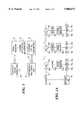
- FIG. 1shows a block diagram illustrating in a general manner a video signal transmission monitoring system embodying the present invention
- FIG. 1Ashows a block diagram of an embodiment of the present monitoring system applied to a cascaded video signal transmission system
- FIGS. 1B and 1Cshow block diagrams of two further embodiments of the present monitoring system
- FIG. 2shows a block diagram of parts of the monitoring system of FIG. 1A at a location remote from the headend of the system;
- FIG. 3shows parts of the monitoring system at a monitoring location
- FIGS. 4 and 5are diagrams illustrating the operation of a computer forming part of the monitoring system of FIG. 1A.
- a video signal transmission headend 10 in the form of a broadband transmitterprovides analog video signals which are received at a remote predetermined site or location by a signal receiver 12.
- the signal receiver 12may be an optical receiver, an antenna, or any other device which enables the capture of a broadband signal to provide an electrical equivalent in a useable frequency range.
- a channel selector 14selects from the received signal a channel to be monitored and measures parameters of the selected signal.
- Corresponding measurement data and the selected received entire video signalare transmitted by a digitizing optical transmitter 16 over a signal link or conduit in the form of a fibre optic cable 18 to a monitoring unit 20 at a monitoring location, which may be at the headend or at some other location.
- the signalis recovered and displayed on a video monitor (not shown) and analysed both for audio and video content and the measurement data is compared with reference data stored for the purpose.
- the channel selectionis made manually by an operator or automatically by a control computer (not shown) at the monitoring location.
- Channel selection information for operating the channel selection device 14is embedded into the transmitted video signal emanating from the transmitter at the headend 10 and is interpreted by the channel selection device at the remote site.
- FIG. 1Ashows a somewhat more complicated transmission and monitoring system than that of FIG. 1.
- the headend 10is connected to an optical fibre cable 11 for transmitting the video signal, the cable being provided with optical amplifiers 13a, 13b. . . 13n in cascade at respective predetermined locations or sites, each of which has, at its output, an optical coupler in the form of a splitter 15a, 15b . . . 15n for capturing the video signal and supplying it to a respective signal receiver 12a, 12b . . . 12n and a channel selector 14a, 14b . . . 14n, corresponding to the signal receiver 12 and the channel selector 14 of FIG. 1.
- the outputs of the channel selectors 14a, 14b. . . 14nare connected to respective, electronic two-way switches 17a,17b . . . 17n connected between respective opto-electronic transmitters 19a, 19b . . . 19n and opto-electronic receivers 21a, 21b . . . 21n in a common signal conduit link comprising an optical fibre cable 18.
- the video signalis captured and the channel is selected by the respective channel selector 14a, 14b . . . 14n.
- the selected signal and the associated measurement dataare provided as one input to the respective switch 17a, 17b . . .. 17n.
- the switch 17a, 17b . . . 17ncan select either this selected local signal from the respective channel selector 14a, 14b . . . 14n or a signal from the respective receiver 21a, 21b . . . 21n.
- the central monitoring locationcan thus analyse the signal selected at any of the channel selectors 14a, 14b . . .14n. Since the signal from each transmitter 19a, 19b . . . 19n is in a digital format, it can be repeated almost indefinitely without any loss of information.
- FIG. 2shows in block diagram form the components of the channel selector 14a, which obtains the analog video signal from the cable 11 by an input comprising the optical splitter 15a and the receiver 12a, which receives the optical signal extracted by the optical splitter 15a and converts it into an electrical RF signal.
- the optical receiver 12ais of known construction and comprises a PIN diode coupled to an RF amplifier.
- the inputcomprises an RF coupler 23.
- an antenna 24 for receiving the video signal as a radio signalwhich is supplied to a down convertor 25 connected to the coupler 23.
- the RF signalis split by a splitter 27, one leg being fed to a down converter 26 and the other leg being sent to an RF modem 28.
- the modem 28demodulates programming information comprising a channel selection control signal sent by a central processor (not shown) as a data carrier generated in the headend.
- the control signalis interpreted by a microprocessor 30 and used to control the frequency of a phase locked loop 32. This frequency in turn controls the frequency of the down converter 26 and thereby effects the video signal channel selection.
- the frequency of the down converter outputis typically an IF signal of 45.75 MHZ.
- the output of the down converter 26is fed to a first demodulator 34, which turns the IF signal into a baseband signal in the 0 to 6 MHZ range (for an NTSC system).
- This signalconsists of NTSC video information including luminance, a chrominance subcarrier and an audio subcarrier. Similar compositions but with different frequency components would be employed for a PAL or SECAM signal.
- the demodulator 34has two output paths. A first path extends to an audio demodulator 36 and the other extends to an analog-to-digital converter 38.
- the resolution of the analog-to-digital converter 38is chosen carefully so as not to degrade the performance of the received signal.
- the analog-to-digital converter 38provides 8 bit resolution giving a theoretical signal-to-noise ratio of approximately 60 dB.
- the demodulator 34has a signal-to-noise ratio of about 52 dB, and since visual problems are visible at about 45 to 48 dB, the digitizing process has sufficient headroom so as not to degrade the signal being sent to the monitoring location.
- the audio demodulator 36turns the BTSC encoded audio subcarrier into stereo left and right audio channels. Other appropriate demodulators would be used to demodulate mono audio and/or secondary audio programming (SAP).
- SAPsecondary audio programming
- the audio demodulator 36has two outputs for the left and right stereo channels, respectively.
- the two stereo channelsare further encoded by analog-to-digital converters 37a and 37b, followed by a high speed multiplexer 35 which converts the two serial bitstreams from the analog-to-digital converters 37a and 3 7b to a single serial bitstream for input to a multiplexer 43.
- the output from the analog-to-digital converter 38is an 8 bit parallel format and the multiplexer 43 is designed to accept 10 parallel bits.
- one bitcomes from the audio multiplexer 35 and the final bit comprises digital data information from the microprocessor 30.
- error correction codesare embedded and transmitted as overhead bits.
- the digital data informationis supplied as direct feed from the microprocessor 30 and comprises digitally encoded information comprising signal quality data indicative of the quality of the selected channel of the analog video signal and local status information provided by the microprocessor 30.
- the signal quality datacomprises the video carrier power level obtained from the down converter 26, the video carrier frequency obtained from the phase locked loop 32, the audio carrier frequency obtained from the demodulator 34 and the audio carrier level obtained from the audio modulator.
- the local status informationis provided in the form of analog inputs to an analog multiplexer 45.
- the amplifier 13acomprises an amplifier sold by Photon Systems Corp. of Burnaby, B.C., Canada as Model No. LT4000-A and incorporates means for providing , as such local status information, analog signals indicating the amplifier status.
- the analog inputsmay also include temperature and other local status information from sources known in the art.
- the analog multiplexer 45effects port-to-port sampling of these analog inputs and measures the values of these inputs as analog values, which it inputs to an analog-to-digital converter 46, which outputs corresponding digital data to the microprocessor 30.
- the multiplexer 45 and the analog-to-digital converter 46are both controlled by the microprocessor 30.
- An alternative arrangementwhich is not shown in the drawings but which is appropriate where fast sampling is required, employs individual analog-to-digital converters for converting respective ones of the analog inputs into digital inputs to a digital multiplexer, which is sampled by the microprocessor 30.
- the multiplexer 43encodes the parallel input signals into a high speed serial bitstream, which is one of the inputs to the high speed switch 17a, which can be made to select between two input positions based on a signal from the local microprocessor 30, which in turn is based on a signal received from the headend 10.
- the second input to the switchis from the local digital receiver and reprocessor 21a, which recovers a digital bitstream from the next transmitter in line, i.e. the transmitter 19b, and reconstructs a clean signal consisting of the usual ones and zeros.
- the corresponding signalis used as an input to the digital optical transmitter 19a for transmission back to the headend 10.
- the channel selectors 14b . . . 14nare similar to the channel selector 14a.
- the digitally encoded format of the video and audio baseband signal sent to the monitoring locationmay be digitally repeated many times without degradation of the signal.
- a plurality of respective signal conduits in the form of individual fibre-optic cables 18a, 18b . . . 18nmay be provided, as shown in FIG. 1B, for connecting the transmitters 19a, 19b . . . 19n to respective receivers 50a, 50b . . . 50n, provided with a selector switch 51, at the monitoring location.
- each transmitter 19a, 19b . . . 19nis connected by a respective coupler 51a, 51b . . . 51n to a common signal conduit comprising a fibre-optic cable 18x, which may comprise the video signal transmission cable 11.
- each of the transmitters 19a, 19b . . . 19nhas a respective optical wavelength f a ,f b . . . f n .
- These wave lengthsare demultiplexed at the monitoring location by a splitter 53 and filtered by respective optical bandpass filters 55a, 55b . . . 55n.
- This arrangementpermits the use of an optical amplifier (not shown) to boost the signals along the cable 18x.
- this arrangementprovides a sample from each of the transmitters 19a, 19b . . . 19n without requiring means for selecting one of these transmitters, which may be advantageous since it allows a plurality of monitors to be simultaneously scanned by one operator.
- the components of the monitoring unit 20are shown in FIG. 3. These comprise a digital opto-electronic video receiver 50 connected to the cable 18, the receiver 50 being compatible with the transmitter 19a and feeding into a demultiplexer 52. Eight bits of a 10 bit output bus of the demultiplexer 52 go to a video digital-to-analog converter 54 to reconstitute the video signal and its sub-carriers. An audio bit bus goes to an audio digital-to-analog converter 56 and a third data bit bus goes directly to a control computer 58 for analysis of the digitized performance information.
- the video digital-to-analog converter 54provides a baseband signal output which contains both video and audio information which is a representation of the signal as encoded at the channel selector 14a, 14b . . . 14n. To analyze this information, the output is split by a splitter 59 into four paths. A main path extends to a video monitor 60 which displays a video image for visual analysis of the signal. The monitor 60 will show distortions present in the signal which may not be measurable by any other means. Such distortions are usually manifest as bars or narrow lines at some angle across the screen and will either move or be stationary.
- a second pathis used as input to a video analyser 62, which in the present embodiment of the invention comprises a Tektronix VM 700, manufactured by Tektronix Inc., of Beaverton, Oreg.
- the video analyzer 62measures signal quality parameters such as signal-to-noise ratio, differential gain, differential phase and other video parameters referenced in the video specification EIA RS-250.
- the data from the video analyzer 62is acquired by the control computer 38 and displayed on a computer monitor 64.
- the computer 58compares the present values of these video parameters to reference data, stored on a hard drive 63 in the computer 58, to monitor the performance over a period of time. By automating this process, the computer 58 monitors the system performance by polling, i.e. by requesting data from each channel selector 14a, 14b . . . 14n and making the required comparisons on a continuous basis.
- a third leg from the splitter 59is fed to a decoder 66, which can demodulate information encoded in the video signal, for example channel insertion (used for advert deletion and substitution), scrambler and set top information. This information can be checked for accuracy, assessed for errors and displayed by a computer monitor 64.
- a decoder 66can demodulate information encoded in the video signal, for example channel insertion (used for advert deletion and substitution), scrambler and set top information. This information can be checked for accuracy, assessed for errors and displayed by a computer monitor 64.
- a fourth leg from the splitter 59is fed to a BTSC stereo audio decoder 68 which recreates the left and right audio channel from the BTSC standard signal.
- the audio digital-to-analog converter 56recovers two audio channels, which may comprises the left and right stereo signals and provides them as inputs to a switch 69, which is controlled by the control computer 58 through a control line 71 and which selects either the locally decoded stereo signal from the BTSC decoder 68 or the remotely decoded signal from the digital-to-analog connecter 56 as input to an audio analyzer 70.
- the audio analyzer 70performs measurements of parameters such as signal-to-noise ratio and harmonic distortion. The outputs of the audio analyzer 70 are fed to the computer 58 for analysis, comparison and display in a manner similar to the video information.
- the digital carriers derived from the microprocessor in the fieldcontain encoded information such as video level, video carrier frequency, audio carrier level, audio carrier frequency plus other digitally encoded information such as temperature at the site or in the equipment, relative humidity and status of the amplifier or site equipment.
- Other digital bitstreams, e.g. telephone or 56 kb/sec channels, separate from the function of this equipmentcould also be included.
- the computer 58has an input device 73 in the form of a keyboard or mouse, by which an operator can input instruction with the computer 58 identifying the video signal channel which is to be selected and the location at which the selection is to be effected.
- the computer 58then outputs corresponding data in the form of the channel selector control signal to an RF modem 72, which encodes the data by FSK encoding onto an RF carrier of a frequency chosen not to interfere with the video signal on the cable 11.
- QPSK encodingmay alternatively be employed.
- the RF carrieris then supplied to a transmitter 75 at the headend 10 for transmission along the cable 11 to the respective channel selector 14a, 14b . . . 14n.
- the computer 58thus comprises a channel selection control signal generator for controlling the channel selection by the respective channel selector 14a, 14b . . . 14n.
- FIG. 4shows the sequence for initializing the measurements and collecting the results in the computer 58.
- Two operator parameters input into the computer 58 by the input device 73are the frequency of sampling and the sampling rate for each site and channel. The former determines the number of samples that comprises a reading and typically would be averaged. The second determines how long the measurements are taken at each site and which channels are measured. It could arise that a particular channel is of more interest than others, either because it is being used to transmit a test signal for system performance evaluation or because of a suspected frequency-related problem with the system.
- a test signalhas the advantage that it is a steady state condition and hence enables more accurate performance measurements.
- FIG. 5shows the measurement validation procedure.
- a reading taken as part of the routine of FIG. 4is compared to data stored on the hard disk 63.
- the difference between that reading and the stored datacould be either:
- the system performance parameter to be monitoredis selected by programming.
- a parametermight be video signal-to-noise ratio.
- the value gatheredis validated by comparison with stored data representing both a range of acceptable values predetermined at the time of the system commissioning and an indication of change in the parameter being measured over the value obtained at the previous reading. The amount of the change or deviation gives rise to varying levels of alarms according to the severity as outlined above.
- the diagnosis routineis described in the following truth table.
- the routinedetermines the type of failure and its location. When an alarm is displayed in FIG. 5, the site, channel and the type of failure are known.
Landscapes
- Engineering & Computer Science (AREA)
- Signal Processing (AREA)
- Computer Networks & Wireless Communication (AREA)
- Databases & Information Systems (AREA)
- Multimedia (AREA)
- Testing, Inspecting, Measuring Of Stereoscopic Televisions And Televisions (AREA)
- Closed-Circuit Television Systems (AREA)
- Selective Calling Equipment (AREA)
Abstract
Description
______________________________________ Preceding Present Subsequent Possible Diagnosis ______________________________________ Single Channel .check mark. .check mark. .check mark. Channel OK X X X Repeat procedure making preceding site present site, if first site OK then headend failure .check mark. X X Check all channels, if OK, then monitor equipment maintenance required .check mark. .check mark. X Repeat procedure making subsequent site present site .check mark. X .check mark. Monitor equipment maintenance required All Channels .check mark. .check mark. .check mark. System OK X X X Repeat procedure making preceding site present site, if first site OK then headend failure .check mark. X X Equipment at present site requires maintenance .check mark. .check mark. X Repeat procedure making subsequent site present site .check mark. X .check mark. Monitor equipment maintenance required ______________________________________
Claims (28)
Applications Claiming Priority (2)
| Application Number | Priority Date | Filing Date | Title |
|---|---|---|---|
| CA2136567 | 1994-11-24 | ||
| CA002136567ACA2136567C (en) | 1994-11-24 | 1994-11-24 | Apparatus and method for remote monitoring of video signals |
Publications (1)
| Publication Number | Publication Date |
|---|---|
| US5808671Atrue US5808671A (en) | 1998-09-15 |
Family
ID=4154731
Family Applications (1)
| Application Number | Title | Priority Date | Filing Date |
|---|---|---|---|
| US08/561,874Expired - LifetimeUS5808671A (en) | 1994-11-24 | 1995-11-22 | Apparatus and method for remote monitoring of video signals |
Country Status (2)
| Country | Link |
|---|---|
| US (1) | US5808671A (en) |
| CA (1) | CA2136567C (en) |
Cited By (48)
| Publication number | Priority date | Publication date | Assignee | Title |
|---|---|---|---|---|
| US6002422A (en)* | 1997-01-06 | 1999-12-14 | Motorola, Inc. | Method for signal level monitoring |
| US6178455B1 (en) | 1997-01-17 | 2001-01-23 | Scientific-Atlanta, Inc. | Router which dynamically requests a set of logical network addresses and assigns addresses in the set to hosts connected to the router |
| US6211926B1 (en)* | 1996-11-20 | 2001-04-03 | Hyundai Electronics Industries Co., Ltd. | Remote control apparatus for digital cable television system and method thereof |
| US6230203B1 (en) | 1995-10-20 | 2001-05-08 | Scientific-Atlanta, Inc. | System and method for providing statistics for flexible billing in a cable environment |
| US6243568B1 (en)* | 1997-03-22 | 2001-06-05 | Sharp Laboratories Of America, Inc. | System and method for intuitively indicating signal quality in a wireless digital communications network |
| US6269482B1 (en)* | 1997-07-14 | 2001-07-31 | Altinex, Inc. | Methods of testing electrical signals and compensating for degradation |
| US6272150B1 (en)* | 1997-01-17 | 2001-08-07 | Scientific-Atlanta, Inc. | Cable modem map display for network management of a cable data delivery system |
| US6286058B1 (en) | 1997-04-14 | 2001-09-04 | Scientific-Atlanta, Inc. | Apparatus and methods for automatically rerouting packets in the event of a link failure |
| US6291983B1 (en)* | 1998-04-24 | 2001-09-18 | International Business Machines Corporation | Selecting and monitoring signal lines with spurious transients in broadband network |
| US20010028411A1 (en)* | 2000-03-27 | 2001-10-11 | Yoshizou Honda | Moving image reception quality determination apparatus |
| US6377299B1 (en)* | 1998-04-01 | 2002-04-23 | Kdd Corporation | Video quality abnormality detection method and apparatus |
| US6380971B1 (en)* | 1999-05-28 | 2002-04-30 | Qwest Communications International Inc. | VDSL video/data set top test equipment |
| US20020140867A1 (en)* | 2001-03-30 | 2002-10-03 | Weiss S. Merrill | Digital signal transmitter synchronization system |
| US6467091B1 (en) | 1995-10-20 | 2002-10-15 | Scientific-Atlanta, Inc. | Constant bit rate transport in a contention based medium access control |
| US20020163963A1 (en)* | 2001-04-23 | 2002-11-07 | Leitch Technology International Inc. | Data monitoring system |
| US6493024B1 (en)* | 1997-09-11 | 2002-12-10 | Hamlet Video International Limited | Signal monitoring apparatus |
| US20030058955A1 (en)* | 2001-07-11 | 2003-03-27 | Sreen Raghavan | High-speed communications transceiver |
| US20030086001A1 (en)* | 2001-04-17 | 2003-05-08 | General Instrument Corporation | Methods and apparatus for the measurement of video quality |
| US20030087634A1 (en)* | 2001-07-11 | 2003-05-08 | Raghavan Sreen A. | 10165368High-speed multi-channel communications transceiver with inter-channel interference filter |
| US20030134607A1 (en)* | 2001-07-11 | 2003-07-17 | Raghavan Sreeen A. | Multi-channel communications transceiver |
| US20030212994A1 (en)* | 2002-05-09 | 2003-11-13 | Radiant Communications Corporation | Remote monitoring system |
| US20030210352A1 (en)* | 2002-05-09 | 2003-11-13 | Fitzsimmons John E. | Remote monitoring system |
| US20040088733A1 (en)* | 2002-11-04 | 2004-05-06 | Havens Daniel W. | Broadband network test system and method |
| US20040160622A1 (en)* | 2000-08-25 | 2004-08-19 | Kddi Corporation | Apparatus for assessing quailty of a picture in transmission, and apparatus for remote monitoring quality of a picture in transmission |
| WO2004100604A1 (en)* | 2000-02-18 | 2004-11-18 | Arris International, Inc. | Reciprocal index lookup for btsc compatible coefficients |
| US20040247022A1 (en)* | 2003-06-03 | 2004-12-09 | Raghavan Sreen A. | Near-end, far-end and echo cancellers in a multi-channel transceiver system |
| US20050114879A1 (en)* | 2003-11-20 | 2005-05-26 | General Instrument Corporation | Monitoring signal quality on a cable network |
| US20050155679A1 (en)* | 2003-04-09 | 2005-07-21 | Coastcast Corporation | CoCr alloys and methods for making same |
| US20050178818A1 (en)* | 1998-12-25 | 2005-08-18 | Kiyokazu Kobayashi | Method of joining steel members, method of processing joined surface of steel member and reinforcing member |
| US6983327B2 (en) | 1996-04-03 | 2006-01-03 | Scientific-Atlanta, Inc. | System and method for providing statistics for flexible billing in a cable environment |
| US20060046851A1 (en)* | 2004-08-24 | 2006-03-02 | Hewlett-Packard Development Company, L.P. | Remote gaming and projection |
| US20060229751A1 (en)* | 2005-04-04 | 2006-10-12 | Barnhill Matthew S | Signal quality estimation and control system |
| US20070047542A1 (en)* | 2005-08-30 | 2007-03-01 | Microsoft Corporation | Real-time audio-visual quality monitoring in a network |
| US20070058043A1 (en)* | 2005-08-30 | 2007-03-15 | Microsoft Corporation | Real-time IPTV channel health monitoring |
| US20080168520A1 (en)* | 2007-01-05 | 2008-07-10 | Verozon Services Corp. | System for testing set-top boxes and content distribution networks and associated methods |
| US20080317114A1 (en)* | 1999-02-18 | 2008-12-25 | Easley Matthew F | Reciprocal Index Lookup for BTSC Compatible Coefficients |
| US7568207B1 (en) | 2000-06-23 | 2009-07-28 | Braun Warren L | Cable drop monitor with upstream signalling |
| US20090273714A1 (en)* | 2008-04-30 | 2009-11-05 | Mediatek Inc. | Digitized analog tv signal processing system |
| US20100188513A1 (en)* | 2009-01-29 | 2010-07-29 | Victor Joseph Duvanenko | System and method for monitoring connections within an analog video system |
| US8006668B1 (en) | 2006-06-29 | 2011-08-30 | Econtrols, Inc. | Electronic pressure regulator |
| US8136506B1 (en) | 2006-06-29 | 2012-03-20 | Econtrols, Inc. | Electronic pressure regulator |
| US8176897B1 (en) | 2006-06-29 | 2012-05-15 | E-Controls, Inc. | Electronic pressure regulator |
| EP2062440A4 (en)* | 2006-08-25 | 2014-03-19 | Verizon Lab Inc | Measurement of video quality at customer premises |
| EP2589220A4 (en)* | 2010-06-30 | 2014-07-23 | Vidyo Inc | Video feedback loop |
| US8983768B1 (en) | 2005-02-11 | 2015-03-17 | Enovation Controls, Llc | Event sensor |
| US9052717B1 (en) | 2004-02-11 | 2015-06-09 | Enovation Controls, Llc | Watercraft speed control device |
| US9207675B1 (en) | 2005-02-11 | 2015-12-08 | Enovation Controls, Llc | Event sensor |
| CN105592358A (en)* | 2015-12-29 | 2016-05-18 | 合肥宏晶微电子科技股份有限公司 | Software and hardware cooperative VGA mode identification method |
Citations (7)
| Publication number | Priority date | Publication date | Assignee | Title |
|---|---|---|---|---|
| US4550407A (en)* | 1982-06-18 | 1985-10-29 | Couasnon Tristan De | Method of analyzing broadcast data, a network analyzer implementing such a method, and receiver equipment using such an analyzer |
| US4558358A (en)* | 1981-05-27 | 1985-12-10 | Pioneer Electronic Corporation | Cable network monitoring system for CATV system |
| US4760442A (en)* | 1985-07-10 | 1988-07-26 | American Telephone And Telegraph Company, At&T Bell Laboratories | Wideband digital signal distribution system |
| US4845711A (en)* | 1986-01-17 | 1989-07-04 | Societe Anonyme De Telecommunications (S.A.T.) | Multiplexing and demultiplexing method and equipments measuring transmission quality and locating operation faults on multiplexed digital channels |
| US4991011A (en)* | 1988-12-23 | 1991-02-05 | Scientific-Atlanta, Inc. | Interactive television terminal with programmable background audio or video |
| US5329311A (en)* | 1993-05-11 | 1994-07-12 | The University Of British Columbia | System for determining noise content of a video signal in the disclosure |
| US5510855A (en)* | 1991-06-18 | 1996-04-23 | Matsushita Electric Industrial Co., Ltd. | Satellite television broadcasting receiver including improved clamping circuit |
- 1994
- 1994-11-24CACA002136567Apatent/CA2136567C/ennot_activeExpired - Fee Related
- 1995
- 1995-11-22USUS08/561,874patent/US5808671A/ennot_activeExpired - Lifetime
Patent Citations (7)
| Publication number | Priority date | Publication date | Assignee | Title |
|---|---|---|---|---|
| US4558358A (en)* | 1981-05-27 | 1985-12-10 | Pioneer Electronic Corporation | Cable network monitoring system for CATV system |
| US4550407A (en)* | 1982-06-18 | 1985-10-29 | Couasnon Tristan De | Method of analyzing broadcast data, a network analyzer implementing such a method, and receiver equipment using such an analyzer |
| US4760442A (en)* | 1985-07-10 | 1988-07-26 | American Telephone And Telegraph Company, At&T Bell Laboratories | Wideband digital signal distribution system |
| US4845711A (en)* | 1986-01-17 | 1989-07-04 | Societe Anonyme De Telecommunications (S.A.T.) | Multiplexing and demultiplexing method and equipments measuring transmission quality and locating operation faults on multiplexed digital channels |
| US4991011A (en)* | 1988-12-23 | 1991-02-05 | Scientific-Atlanta, Inc. | Interactive television terminal with programmable background audio or video |
| US5510855A (en)* | 1991-06-18 | 1996-04-23 | Matsushita Electric Industrial Co., Ltd. | Satellite television broadcasting receiver including improved clamping circuit |
| US5329311A (en)* | 1993-05-11 | 1994-07-12 | The University Of British Columbia | System for determining noise content of a video signal in the disclosure |
Cited By (90)
| Publication number | Priority date | Publication date | Assignee | Title |
|---|---|---|---|---|
| USRE44211E1 (en) | 1995-10-20 | 2013-05-07 | Scientific-Atlanta, Llc | Constant bit rate transport in a contention based medium access control |
| US6230203B1 (en) | 1995-10-20 | 2001-05-08 | Scientific-Atlanta, Inc. | System and method for providing statistics for flexible billing in a cable environment |
| US6467091B1 (en) | 1995-10-20 | 2002-10-15 | Scientific-Atlanta, Inc. | Constant bit rate transport in a contention based medium access control |
| US6983327B2 (en) | 1996-04-03 | 2006-01-03 | Scientific-Atlanta, Inc. | System and method for providing statistics for flexible billing in a cable environment |
| US7028088B1 (en) | 1996-04-03 | 2006-04-11 | Scientific-Atlanta, Inc. | System and method for providing statistics for flexible billing in a cable environment |
| US6211926B1 (en)* | 1996-11-20 | 2001-04-03 | Hyundai Electronics Industries Co., Ltd. | Remote control apparatus for digital cable television system and method thereof |
| US6002422A (en)* | 1997-01-06 | 1999-12-14 | Motorola, Inc. | Method for signal level monitoring |
| US6308328B1 (en) | 1997-01-17 | 2001-10-23 | Scientific-Atlanta, Inc. | Usage statistics collection for a cable data delivery system |
| US6405253B1 (en) | 1997-01-17 | 2002-06-11 | Scientific-Atlanta, Inc. | Dynamic allocation of a set of addresses to router RF modem for individual assignment to hosts |
| US6282208B1 (en) | 1997-01-17 | 2001-08-28 | Scientific-Atlanta, Inc. | Data traffic control in a data modem system |
| US6922412B2 (en) | 1997-01-17 | 2005-07-26 | Scientific-Atlanta, Inc. | Methods for dynamically assigning link addresses and logical network addresses |
| US6178455B1 (en) | 1997-01-17 | 2001-01-23 | Scientific-Atlanta, Inc. | Router which dynamically requests a set of logical network addresses and assigns addresses in the set to hosts connected to the router |
| US6301223B1 (en) | 1997-01-17 | 2001-10-09 | Scientific-Atlanta, Inc. | Method of using routing protocols to reroute packets during a link failure |
| US8522265B2 (en) | 1997-01-17 | 2013-08-27 | Scott E. Hrastar | Modem apparatus for a cable data delivery system |
| US6618353B2 (en) | 1997-01-17 | 2003-09-09 | Scientific-Atlanta, Inc. | Router for use with a link that has a set of concurrent channels |
| US6324267B1 (en) | 1997-01-17 | 2001-11-27 | Scientific-Atlanta, Inc. | Two-tiered authorization and authentication for a cable data delivery system |
| US6529517B2 (en) | 1997-01-17 | 2003-03-04 | Scientific-Atlanta, Inc. | Router for which a logical network address which is not unique to the router is the gateway address in default routing table entries |
| US6519224B2 (en) | 1997-01-17 | 2003-02-11 | Scientific-Atlanta, Inc. | Method of using routing protocols to reroute packets during a link failure |
| US6272150B1 (en)* | 1997-01-17 | 2001-08-07 | Scientific-Atlanta, Inc. | Cable modem map display for network management of a cable data delivery system |
| US7099308B2 (en) | 1997-01-17 | 2006-08-29 | Scientific-Atlantic, Inc. | Router for use with a link that has a set of concurrent channels |
| US6249523B1 (en) | 1997-01-17 | 2001-06-19 | Scientific-Atlanta, Inc. | Router for which a logical network address which is not unique to the gateway address in default routing table entries |
| US6208656B1 (en) | 1997-01-17 | 2001-03-27 | Scientific-Atlanta, Inc. | Methods for dynamically assigning link addresses and logical network addresses |
| US6243568B1 (en)* | 1997-03-22 | 2001-06-05 | Sharp Laboratories Of America, Inc. | System and method for intuitively indicating signal quality in a wireless digital communications network |
| US6286058B1 (en) | 1997-04-14 | 2001-09-04 | Scientific-Atlanta, Inc. | Apparatus and methods for automatically rerouting packets in the event of a link failure |
| US6269482B1 (en)* | 1997-07-14 | 2001-07-31 | Altinex, Inc. | Methods of testing electrical signals and compensating for degradation |
| US6493024B1 (en)* | 1997-09-11 | 2002-12-10 | Hamlet Video International Limited | Signal monitoring apparatus |
| US6377299B1 (en)* | 1998-04-01 | 2002-04-23 | Kdd Corporation | Video quality abnormality detection method and apparatus |
| US6291983B1 (en)* | 1998-04-24 | 2001-09-18 | International Business Machines Corporation | Selecting and monitoring signal lines with spurious transients in broadband network |
| US20050178818A1 (en)* | 1998-12-25 | 2005-08-18 | Kiyokazu Kobayashi | Method of joining steel members, method of processing joined surface of steel member and reinforcing member |
| US20080317114A1 (en)* | 1999-02-18 | 2008-12-25 | Easley Matthew F | Reciprocal Index Lookup for BTSC Compatible Coefficients |
| US7940842B2 (en) | 1999-02-18 | 2011-05-10 | That Corporation | Reciprocal index lookup for BTSC compatible coefficients |
| US7050090B2 (en) | 1999-05-28 | 2006-05-23 | Qwest Communications International Inc. | VDSL video/data set top test equipment |
| US20020126207A1 (en)* | 1999-05-28 | 2002-09-12 | Qwest Communications International, Inc. | VDSL video/data set top test equipment |
| US6380971B1 (en)* | 1999-05-28 | 2002-04-30 | Qwest Communications International Inc. | VDSL video/data set top test equipment |
| WO2004100604A1 (en)* | 2000-02-18 | 2004-11-18 | Arris International, Inc. | Reciprocal index lookup for btsc compatible coefficients |
| US20010028411A1 (en)* | 2000-03-27 | 2001-10-11 | Yoshizou Honda | Moving image reception quality determination apparatus |
| US7568207B1 (en) | 2000-06-23 | 2009-07-28 | Braun Warren L | Cable drop monitor with upstream signalling |
| US7068304B2 (en)* | 2000-08-25 | 2006-06-27 | Kddi Corporation | Apparatus for assessing quality of a picture in transmission, and apparatus for remote monitoring quality of a picture in transmission |
| US20040160622A1 (en)* | 2000-08-25 | 2004-08-19 | Kddi Corporation | Apparatus for assessing quailty of a picture in transmission, and apparatus for remote monitoring quality of a picture in transmission |
| US7667780B2 (en)* | 2001-03-30 | 2010-02-23 | Weiss S Merrill | Digital signal transmitter synchronization system |
| US20060143677A1 (en)* | 2001-03-30 | 2006-06-29 | Weiss S M | Digital signal transmitter synchronization system |
| US7110048B2 (en)* | 2001-03-30 | 2006-09-19 | Weiss S Merrill | Digital signal transmitter synchronization system |
| US20020140867A1 (en)* | 2001-03-30 | 2002-10-03 | Weiss S. Merrill | Digital signal transmitter synchronization system |
| US6734898B2 (en)* | 2001-04-17 | 2004-05-11 | General Instrument Corporation | Methods and apparatus for the measurement of video quality |
| US20030086001A1 (en)* | 2001-04-17 | 2003-05-08 | General Instrument Corporation | Methods and apparatus for the measurement of video quality |
| US7161617B2 (en)* | 2001-04-23 | 2007-01-09 | Leitch Technology International Inc. | Data monitoring system |
| US20020163963A1 (en)* | 2001-04-23 | 2002-11-07 | Leitch Technology International Inc. | Data monitoring system |
| US7236757B2 (en) | 2001-07-11 | 2007-06-26 | Vativ Technologies, Inc. | High-speed multi-channel communications transceiver with inter-channel interference filter |
| US7403752B2 (en) | 2001-07-11 | 2008-07-22 | Vativ Technologies, Inc. | Multi-channel communications transceiver |
| US7590168B2 (en) | 2001-07-11 | 2009-09-15 | Entropic Communications, Inc. | Low complexity high-speed communications transceiver |
| US20030081693A1 (en)* | 2001-07-11 | 2003-05-01 | Raghavan Sreen A. | Low complexity high-speed communications transceiver |
| US20030058955A1 (en)* | 2001-07-11 | 2003-03-27 | Sreen Raghavan | High-speed communications transceiver |
| US20030134607A1 (en)* | 2001-07-11 | 2003-07-17 | Raghavan Sreeen A. | Multi-channel communications transceiver |
| US7295623B2 (en) | 2001-07-11 | 2007-11-13 | Vativ Technologies, Inc. | High-speed communications transceiver |
| US20030087634A1 (en)* | 2001-07-11 | 2003-05-08 | Raghavan Sreen A. | 10165368High-speed multi-channel communications transceiver with inter-channel interference filter |
| US20030212998A1 (en)* | 2002-05-09 | 2003-11-13 | Radiant Communications Corporation | Channel transmitter unit |
| US20030210352A1 (en)* | 2002-05-09 | 2003-11-13 | Fitzsimmons John E. | Remote monitoring system |
| US20030212994A1 (en)* | 2002-05-09 | 2003-11-13 | Radiant Communications Corporation | Remote monitoring system |
| US20040088733A1 (en)* | 2002-11-04 | 2004-05-06 | Havens Daniel W. | Broadband network test system and method |
| US20050155679A1 (en)* | 2003-04-09 | 2005-07-21 | Coastcast Corporation | CoCr alloys and methods for making same |
| US7388904B2 (en)* | 2003-06-03 | 2008-06-17 | Vativ Technologies, Inc. | Near-end, far-end and echo cancellers in a multi-channel transceiver system |
| US20040247022A1 (en)* | 2003-06-03 | 2004-12-09 | Raghavan Sreen A. | Near-end, far-end and echo cancellers in a multi-channel transceiver system |
| US20050114879A1 (en)* | 2003-11-20 | 2005-05-26 | General Instrument Corporation | Monitoring signal quality on a cable network |
| US9052717B1 (en) | 2004-02-11 | 2015-06-09 | Enovation Controls, Llc | Watercraft speed control device |
| US20060046851A1 (en)* | 2004-08-24 | 2006-03-02 | Hewlett-Packard Development Company, L.P. | Remote gaming and projection |
| US10130877B2 (en) | 2004-08-24 | 2018-11-20 | Hewlett-Packard Development Company, L.P. | Remote gaming and projection |
| US9873042B2 (en) | 2004-08-24 | 2018-01-23 | Hewlett-Packard Development Company, L.P. | Remote gaming and projection |
| US8983768B1 (en) | 2005-02-11 | 2015-03-17 | Enovation Controls, Llc | Event sensor |
| US9207675B1 (en) | 2005-02-11 | 2015-12-08 | Enovation Controls, Llc | Event sensor |
| US9098083B1 (en) | 2005-02-11 | 2015-08-04 | Enovation Controls, Llc | Event sensor |
| US9092033B1 (en) | 2005-02-11 | 2015-07-28 | Enovation Controls, Llc | Event sensor |
| US9068838B1 (en) | 2005-02-11 | 2015-06-30 | Enovation Controls, Llc | Event sensor |
| US20060229751A1 (en)* | 2005-04-04 | 2006-10-12 | Barnhill Matthew S | Signal quality estimation and control system |
| US8014741B2 (en) | 2005-04-04 | 2011-09-06 | That Corporation | Signal quality estimation and control system |
| WO2006107852A3 (en)* | 2005-04-04 | 2007-10-18 | That Corp | Signal quality estimation and control system |
| US20070058043A1 (en)* | 2005-08-30 | 2007-03-15 | Microsoft Corporation | Real-time IPTV channel health monitoring |
| US20070047542A1 (en)* | 2005-08-30 | 2007-03-01 | Microsoft Corporation | Real-time audio-visual quality monitoring in a network |
| US8136506B1 (en) | 2006-06-29 | 2012-03-20 | Econtrols, Inc. | Electronic pressure regulator |
| US8286611B1 (en) | 2006-06-29 | 2012-10-16 | Econtrols, Inc. | Electronic pressure regulator |
| US8176897B1 (en) | 2006-06-29 | 2012-05-15 | E-Controls, Inc. | Electronic pressure regulator |
| US8006668B1 (en) | 2006-06-29 | 2011-08-30 | Econtrols, Inc. | Electronic pressure regulator |
| EP2062440A4 (en)* | 2006-08-25 | 2014-03-19 | Verizon Lab Inc | Measurement of video quality at customer premises |
| US8595784B2 (en)* | 2007-01-05 | 2013-11-26 | Verizon Patent And Licensing Inc. | System for testing set-top boxes and content distribution networks and associated methods |
| US20080168520A1 (en)* | 2007-01-05 | 2008-07-10 | Verozon Services Corp. | System for testing set-top boxes and content distribution networks and associated methods |
| US8212941B2 (en)* | 2008-04-30 | 2012-07-03 | Mediatek Inc. | Digitized analog TV signal processing system |
| US20090273714A1 (en)* | 2008-04-30 | 2009-11-05 | Mediatek Inc. | Digitized analog tv signal processing system |
| US8294772B2 (en) | 2009-01-29 | 2012-10-23 | Pelco, Inc. | System and method for monitoring connections within an analog video system |
| US20100188513A1 (en)* | 2009-01-29 | 2010-07-29 | Victor Joseph Duvanenko | System and method for monitoring connections within an analog video system |
| EP2589220A4 (en)* | 2010-06-30 | 2014-07-23 | Vidyo Inc | Video feedback loop |
| CN105592358A (en)* | 2015-12-29 | 2016-05-18 | 合肥宏晶微电子科技股份有限公司 | Software and hardware cooperative VGA mode identification method |
Also Published As
| Publication number | Publication date |
|---|---|
| CA2136567A1 (en) | 1996-05-25 |
| CA2136567C (en) | 2001-01-30 |
Similar Documents
| Publication | Publication Date | Title |
|---|---|---|
| US5808671A (en) | Apparatus and method for remote monitoring of video signals | |
| EP0986269B1 (en) | In-service realtime picture quality analysis | |
| US5982412A (en) | Coaxial testing and provisioning network interface device | |
| US5629739A (en) | Apparatus and method for injecting an ancillary signal into a low energy density portion of a color television frequency spectrum | |
| US6734898B2 (en) | Methods and apparatus for the measurement of video quality | |
| US6600515B2 (en) | Pulsed leakage tagging signal | |
| US4408227A (en) | Method and apparatus for television distribution system sweep testing | |
| WO2001078391A2 (en) | Distortion monitoring system for catv transmission networks | |
| HUP0103151A2 (en) | Audio/video signal redistribution system over conductors for communication interfaces and method for operating said system | |
| US4408345A (en) | Remote line monitoring method and device for CATV system | |
| JPH02108386A (en) | Catv system | |
| US9774847B2 (en) | Dual-port testing of a cable network | |
| KR100414456B1 (en) | Apparatus and method for monitoring polarization mode dispersion and chromatic dispersion in optical network | |
| US20070212073A1 (en) | Apparatus, System And Method For Optical Signal Transmission | |
| CN108012148B (en) | Device and method for monitoring and automatically switching audio quality of broadcast television in real time | |
| US5956074A (en) | Cable television return display unit | |
| Lu et al. | Clipping-induced impulse noise and its effect on bit-error performance in AM-VSB/64QAM hybrid lightwave systems | |
| US7254828B2 (en) | Multiple input data receiver for cable television systems | |
| US20060270340A1 (en) | Apparatus and method for distributing signals by down-converting to vacant channels | |
| KR100813566B1 (en) | HFC transmission network monitoring device | |
| JPH07231298A (en) | Optical transmission method | |
| US20120230683A1 (en) | System and Method for Remotely Monitoring Communication Equipment and Signals | |
| KR100366234B1 (en) | Apparatus of filtering noise for providing internet service using master antenna television network | |
| JPH06224881A (en) | Optical transmission system and transceiver of optical transmission system | |
| US6181745B1 (en) | Process for monitoring the quantization quality in digital radio or television transmission systems |
Legal Events
| Date | Code | Title | Description |
|---|---|---|---|
| AS | Assignment | Owner name:AUGAT PHOTON SYSTEMS INC., CANADA Free format text:ASSIGNMENT OF ASSIGNORS INTEREST;ASSIGNORS:MAYCOCK, JOHN CHARLES;RITCHEY, CAREY TODD;SMITH, VINCENT MADDOCK;REEL/FRAME:007780/0007;SIGNING DATES FROM 19951120 TO 19951121 | |
| AS | Assignment | Owner name:THOMAS & BETTS INTERNATIONAL, INC., NEVADA Free format text:ASSIGNMENT OF ASSIGNORS INTEREST;ASSIGNOR:AUGAT PHOTON SYSTEMS, INC.;REEL/FRAME:009334/0351 Effective date:19980630 | |
| STCF | Information on status: patent grant | Free format text:PATENTED CASE | |
| AS | Assignment | Owner name:AUGAT COMMUNICATION PRODUCTS, INC., TENNESSEE Free format text:ASSIGNMENT OF ASSIGNORS INTEREST;ASSIGNOR:THOMAS & BETTS INTERNATIONAL, INC.;REEL/FRAME:010206/0988 Effective date:19990901 | |
| AS | Assignment | Owner name:THOMAS & BETTS - PHOTON SYSTEMS INC., CANADA Free format text:ASSIGNMENT OF ASSIGNORS INTEREST;ASSIGNOR:AUGAT COMMUNICATION PRODUCTS, INC.;REEL/FRAME:010238/0132 Effective date:19990911 | |
| AS | Assignment | Owner name:SCIENTIFIC-ATLANTA, INC., GEORGIA Free format text:ASSIGNMENT OF ASSIGNORS INTEREST;ASSIGNOR:THOMAS & BETTS-PHOTON SYSTEMS, INC.;REEL/FRAME:010470/0858 Effective date:19990914 | |
| FPAY | Fee payment | Year of fee payment:4 | |
| FPAY | Fee payment | Year of fee payment:8 | |
| FPAY | Fee payment | Year of fee payment:12 | |
| AS | Assignment | Owner name:SCIENTIFIC-ATLANTA, LLC, GEORGIA Free format text:CHANGE OF NAME;ASSIGNOR:SCIENTIFIC-ATLANTA, INC.;REEL/FRAME:034299/0440 Effective date:20081205 Owner name:CISCO TECHNOLOGY, INC., CALIFORNIA Free format text:ASSIGNMENT OF ASSIGNORS INTEREST;ASSIGNOR:SCIENTIFIC-ATLANTA, LLC;REEL/FRAME:034300/0001 Effective date:20141118 |