US5808660A - Video on-demand system with a plurality of reception apparatus connected in a daisy chain connection - Google Patents
Video on-demand system with a plurality of reception apparatus connected in a daisy chain connectionDownload PDFInfo
- Publication number
- US5808660A US5808660AUS08/706,291US70629196AUS5808660AUS 5808660 AUS5808660 AUS 5808660AUS 70629196 AUS70629196 AUS 70629196AUS 5808660 AUS5808660 AUS 5808660A
- Authority
- US
- United States
- Prior art keywords
- video
- reception apparatus
- video information
- demand system
- compression coding
- Prior art date
- Legal status (The legal status is an assumption and is not a legal conclusion. Google has not performed a legal analysis and makes no representation as to the accuracy of the status listed.)
- Expired - Lifetime
Links
- 230000006854communicationEffects0.000claimsabstractdescription24
- 238000004891communicationMethods0.000claimsabstractdescription24
- 238000009434installationMethods0.000claimsabstractdescription17
- 230000008929regenerationEffects0.000claimsabstractdescription12
- 238000011069regeneration methodMethods0.000claimsabstractdescription12
- 230000006835compressionEffects0.000claimsdescription33
- 238000007906compressionMethods0.000claimsdescription33
- 230000004044responseEffects0.000claimsdescription18
- 101000969688Homo sapiens Macrophage-expressed gene 1 proteinProteins0.000claimsdescription7
- 102100021285Macrophage-expressed gene 1 proteinHuman genes0.000claimsdescription7
- 239000004973liquid crystal related substanceSubstances0.000claimsdescription7
- 230000007175bidirectional communicationEffects0.000claims3
- 239000011159matrix materialSubstances0.000claims3
- 239000013078crystalSubstances0.000claims1
- 230000005540biological transmissionEffects0.000description103
- 230000002457bidirectional effectEffects0.000description33
- 238000010276constructionMethods0.000description11
- 238000012546transferMethods0.000description9
- 238000006243chemical reactionMethods0.000description6
- 238000000034methodMethods0.000description5
- 238000010586diagramMethods0.000description4
- 230000008859changeEffects0.000description3
- 230000005236sound signalEffects0.000description3
- 238000012986modificationMethods0.000description2
- 230000004048modificationEffects0.000description2
- 238000012545processingMethods0.000description2
- 230000001360synchronised effectEffects0.000description2
- 230000003466anti-cipated effectEffects0.000description1
- 238000012790confirmationMethods0.000description1
- 230000008030eliminationEffects0.000description1
- 238000003379elimination reactionMethods0.000description1
- RGNPBRKPHBKNKX-UHFFFAOYSA-NhexaflumuronChemical compoundC1=C(Cl)C(OC(F)(F)C(F)F)=C(Cl)C=C1NC(=O)NC(=O)C1=C(F)C=CC=C1FRGNPBRKPHBKNKX-UHFFFAOYSA-N0.000description1
- 230000006872improvementEffects0.000description1
- 238000012423maintenanceMethods0.000description1
Images


Classifications
- H—ELECTRICITY
- H04—ELECTRIC COMMUNICATION TECHNIQUE
- H04L—TRANSMISSION OF DIGITAL INFORMATION, e.g. TELEGRAPHIC COMMUNICATION
- H04L12/00—Data switching networks
- H04L12/28—Data switching networks characterised by path configuration, e.g. LAN [Local Area Networks] or WAN [Wide Area Networks]
- H04L12/40—Bus networks
- H04L12/40052—High-speed IEEE 1394 serial bus
- H04L12/40117—Interconnection of audio or video/imaging devices
- H—ELECTRICITY
- H04—ELECTRIC COMMUNICATION TECHNIQUE
- H04N—PICTORIAL COMMUNICATION, e.g. TELEVISION
- H04N7/00—Television systems
- H04N7/10—Adaptations for transmission by electrical cable
- H—ELECTRICITY
- H04—ELECTRIC COMMUNICATION TECHNIQUE
- H04N—PICTORIAL COMMUNICATION, e.g. TELEVISION
- H04N7/00—Television systems
- H04N7/16—Analogue secrecy systems; Analogue subscription systems
- H04N7/173—Analogue secrecy systems; Analogue subscription systems with two-way working, e.g. subscriber sending a programme selection signal
- H04N7/17309—Transmission or handling of upstream communications
- H04N7/17318—Direct or substantially direct transmission and handling of requests
- H—ELECTRICITY
- H04—ELECTRIC COMMUNICATION TECHNIQUE
- H04N—PICTORIAL COMMUNICATION, e.g. TELEVISION
- H04N7/00—Television systems
- H04N7/18—Closed-circuit television [CCTV] systems, i.e. systems in which the video signal is not broadcast
Definitions
- This inventionrelates to a video on-demand system, and more particularly to a video on-demand system which is suitably used in a situation wherein an installation space is limited such as in an aircraft.
- video on-demand systema video distribution system which can provide, to each viewer, a video program desired by the viewer in response to a request of the viewer is being put to practical use.
- the video on-demand systemis being developed as a system which interconnects a distribution center which principally distributes video programs and houses of individuals.
- the systemcan be utilized in such a mobile object as an aircraft, improvement in service to passengers can be anticipated.
- the bit rate of compressed moving pictures distributed using a system of the type described above at presentis as high as 1.5 to 4.0 Mbps, and if it is tried to provide video programs individually to 50 to 60 passengers, then the transmission amount comes up to 75 to 240 Mbps.
- An ATMAsynchronous Transfer Mode
- This data switching systemis disadvantageous in that the system itself is expensive. Further, as a connection form between the delivery apparatus and the reception apparatus, it cannot be avoided to adopt such a point-to-point type connection form as shown in FIG. 12. Consequently, as the number of reception apparatus increases, also the number of lines increases. Accordingly, the data switching system is disadvantageous also in that, where it is utilized in a location where the space is physically limited such as in an aircraft, the number of reception apparatus to be connected cannot be increased readily because of the difficulty in adding wiring lines.
- the reception apparatusare preferably connected to each other by a daisy chain connection.
- a daisy chain connection between terminalsis impossible and does not match with the physical environment.
- the daisy chain connectionhere denotes a form of connection wherein a plurality of reception apparatus each having input terminals and output terminals and having a function of delivering all signals from the input terminals to the output terminals and another function of selectively receiving and processing only a desired one or ones of the signals from the input terminals are connected in cascade connection by the input terminals and the output terminals thereof via lines.
- a video on-demand systemwherein a plurality of video programs are selectively supplied and displayed in response to requests of viewers in a physically limited space
- a delivery apparatusfor selectively reading out and delivering, in response to request signals, video information of the video programs each in the form of compressed codes stored in storage means
- a communication lineincluding a set of lines including a data line for serially transmitting the video information at a data rate equal to or higher than 100 MBps, a strobe line for transmitting a strobe signal for regeneration of a clock signal to be used to transmit the video information and a power supply line for supplying dc power
- a plurality of reception apparatusconnected in a daisy chain connection to the delivery apparatus by the communication line for outputting the request signals and selectively receiving the video information
- a plurality of reception apparatus installation meansarranged in a predetermined form and having the plurality of reception apparatus installed individually therein for allowing the viewers to enjoy the video programs
- a video on-demand systemwherein a plurality of video programs are selectively supplied and displayed in response to requests of viewers in a physically limited space
- a delivery apparatusfor selectively reading out and delivering, in response to request signals, video information of the video programs each in the form of compressed codes stored in storage means via an asynchronous or synchronous serial interface
- a converterfor converting the video information delivered from the transmission apparatus into a set of the video information and a strobe signal for regeneration of a clock signal of the video information
- a communication lineincluding a set of lines including a data line for serially transmitting the video information obtained by the conversion of the converter at a data rate equal to or higher than 100 MBps, a strobe line for transmitting a strobe signal for regeneration of a clock signal to be used to transmit the video information and a power supply line for supplying dc power
- a plurality of reception apparatusconnected in a daisy chain connection to the delivery apparatus by the communication line for outputting the
- a video on-demand systemwherein a plurality of video programs are selectively supplied and displayed in response to requests of viewers in a physically limited space
- a plurality of delivery apparatusfor selectively reading out and delivering, in response to request signals, video information of the video programs each in the form of compressed codes stored in storage means
- an exchangefor selectively connecting the plurality of delivery apparatus and a first communication line
- a converterfor converting the video information supplied thereto from the exchange via the first line into a set of the video information and a strobe signal for regeneration of a clock signal of the video information
- a second communication lineincluding a set of lines including a data line for serially transmitting the video information obtained by the conversion of the converter at a data rate equal to or higher than 100 MBps
- a strobe linefor transmitting a strobe signal for regeneration of a clock signal to be used to transmit the video information and a power supply line for supplying dc power
- a plurality of reception apparatusconnected
- the video on-demand systemssince they are constructed in such a manner as described above, the length of the cable required to connect the reception apparatus to each other can be reduced remarkably comparing with that of related art video on-demand systems. Further, since the connection form is very simple, the cable can be laid readily irrespective of a physical restriction in construction of a system.
- the communication line for use for interconnection between the delivery apparatus and the plurality of reception apparatusincludes a data line for serially transmitting video information at a data rate equal to or higher than 100 MBps, a strobe line for transmitting a strobe signal for regeneration of a clock signal and a power supply line for supplying dc power and the delivery apparatus and the plurality of reception apparatus are connected in a daisy chain connection, the wiring line length can be minimized. Consequently, the video on-demand systems can be applied readily to a location wherein the space which can be used to install wiring lines therein is physically limited such as, for example, in an aircraft.
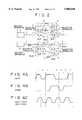
- FIG. 1is a perspective view of an example of a construction of a video on-demand system showing a preferred embodiment of the present invention
- FIG. 2is a diagrammatic view showing a network configuration employed in the video on-demand system shown in FIG. 1;
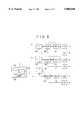
- FIG. 3is a block diagram showing internal constructions of a delivery apparatus and a reception apparatus of the video on-demand system of FIG. 1;
- FIGS. 4A to 4Care signal waveform diagrams illustrating a bidirectional serial transmission standard used in the video on-demand system of FIG. 1;
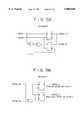
- FIGS. 5A and 5Bare block diagrams showing constructions of an encoder and a decoder of the video on-demand system of FIG. 1, respectively;
- FIGS. 6A and 6Bare diagrammatic views showing data structures in one cycle
- FIGS. 7A and 7Bare diagrammatic views illustrating different data transmission protocols
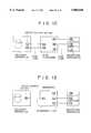
- FIG. 8is a block diagram of a system construction of a video on-demand system showing another preferred embodiment of the present invention.
- FIG. 9is a diagrammatic view illustrating a protocol stack
- FIGS. 10 and 11are diagrammatic views illustrating rough estimates of a load on the delivery apparatus side
- FIG. 12is a diagrammatic view showing a network system which employs an ATM line
- FIG. 13is a similar view but showing a network system which employs an Ethernet line.
- FIG. 14is a diagrammatic view showing a wiring scheme where a related art system is employed.
- FIG. 1shows a basic system configuration which is common to video on-demand systems which can be constructed in an aircraft. More particularly, FIG. 1 shows a general configuration of an video on-demand system which provides video programs (video data (including still picture data) and audio data) to passengers in a passenger cabin of an aircraft in which seats are arranged in a plurality of rows along an aisle such that three seats are arranged on each of the opposite sides of the aisle in each row. It is to be noted that a pair of video on-demand systems are provided independently of each other for the seats on the opposite sides of the aisle and each of the video on-demand systems shown in FIG. 1 is of such a small scale that 50 to 60 reception apparatus are connected to one delivery apparatus.
- video programsvideo data (including still picture data) and audio data
- each of the video on-demand systemsgenerally includes a delivery apparatus 2 for delivering video programs into a transmission line in response to requests of passengers, and a plurality of reception apparatus 4 each for receiving a video program destined for the reception apparatus 4 itself from among the video programs transmitted via the transmission line and displaying the received video program on a display unit 3.
- each of the reception apparatus 4is provided below each seat 5.
- the video on-demand systemtransmits information in conformity with IEEE 1394 which is a bi-directional serial transmission standard which will be hereinafter described such that the reception apparatus 4 are connected to each other by a daisy chain connection. Consequently, the video on-demand system has such a very simplified network configuration as seen in FIG. 2 by the daisy chain connection.
- the network configurationcan be constructed from a single transmission line extending in series from the front seat row toward the rear seat row along one of guide grooves 6 formed on the floor below columns of the seats with the reception apparatus 4 interposed therein, and another transmission line provided for each seat row and extending in series from one of the reception apparatus 4 for a seat at an end of the seat row to another one of the reception apparatus 4 for another seat at the other end of the seat row with an intermediate reception apparatus 4 interposed therein.
- FIG. 2does not particularly show the individual input/output terminals but only represents the connection relationship equivalently.
- the guide groove 6is required to receive, at any location thereof, only one transmission cable 7 which connects the associated reception apparatus 4 in series, and need not receive a number of transmission cables 7 equal to the number of reception apparatus 4 connected to the delivery apparatus 2 which is different from the related art system.
- an operation for constructing a network systemcan be carried out without being restricted from spaces in which transmission cables can be installed, and the present system is convenient also for a designer when the designer carries out designing of the same.
- a physical changing operation of the networkcan be completed by only removing each transmission cable 7 which extends from a reception apparatus 4 for a seat to be removed to another reception apparatus 4 for an adjacent seat.
- the delivery apparatus 2which serves as a server, includes a recording apparatus 2A which may be a hard disk apparatus or like apparatus having a large recording capacity, a control apparatus 2B for controlling the recording apparatus 2A, and a transmission and reception apparatus 2C for transmitting and receiving data in conformity with the bidirectional serial transmission standard IEEE 1394 which will be hereinafter described.
- a recording apparatus 2Awhich may be a hard disk apparatus or like apparatus having a large recording capacity
- a control apparatus 2Bfor controlling the recording apparatus 2A
- a transmission and reception apparatus 2Cfor transmitting and receiving data in conformity with the bidirectional serial transmission standard IEEE 1394 which will be hereinafter described.
- the recording apparatus 2Ahas various video programs stored therein so as to satisfy various requests of passengers. Further, the recording apparatus 2A stores the video programs in two picture qualities for an ordinary image (MPEG1 format image) and a high definition image (MPEG2 format image) which is higher in definition than the ordinary image, and can switchably deliver a different one of the images depending upon the type of an apparatus connected to the network such as, for example, a reception apparatus wherein an image is displayed on a liquid crystal display unit or another reception apparatus wherein an image is displayed using a projector.
- MPEG1 format imagean ordinary image
- MPEG2 format imagehigh definition image
- the control apparatus 2Bcontrols a reading out operation of the recording apparatus 2A in response to a request from any reception apparatus 4 received via the transmission and reception apparatus 2C, converts a video program read out in response to such request, adds a header to each packet and outputs resulting packets to the transmission and reception apparatus 2C.
- the transmission and reception apparatus 2Ctransmits and receives information of a video program and so forth at one of transmission rates of 100 MBps, 200 MBps and 400 MBps in accordance with a transmission rate permitted by the constructed network system.
- each of the reception apparatus 4 provided for the individual seats 5includes a transmission and reception apparatus 4A for receiving video programs delivered from the delivery apparatus 2, a control apparatus 4B for extracting an information program destined for the reception apparatus 4 from among the received video programs, and a decoding apparatus 4C for decoding the extracted information program into a video signal.
- a control unit 8is connected to the control apparatus 4B, and the control apparatus 4B delivers an instruction corresponding to a request inputted from the control unit 8 as control data to the delivery apparatus 2.
- the transmission and reception apparatus 4Ahas a plurality of, actually three, input and/or output terminals for bidirectional data transmission and functions so that all signals from the input terminals are delivered to the output terminals.
- the control unit 8is an operation terminal for a passenger which is removably fixed to an arm rest or a like part of a seat 5 and can input various operations such as selection, reproduction, pause, fast forward and rewinding of a video program therethrough.
- the decoding apparatus 4Cdecodes a video program transmitted thereto as a compression coded signal and displays the decoded video program on the display unit 3.
- a liquid crystal display unitis used for the display unit 3.
- the bidirectional serial transmission standard IEEE 1394 employed in the video on-demand system 1requires a transmission cable 7 including three lines consisting of a power supply line, a data line and a strobe line and communicates data at a transmission rate at least equal to or higher than 100 MBps.
- a transmission cable 7including three lines consisting of a power supply line, a data line and a strobe line and communicates data at a transmission rate at least equal to or higher than 100 MBps.
- one of the three transmission rates of 100 MBps, 200 MBps and 400 MBpScan be selected.
- the power supply lineis used to supply dc power to various apparatus connected thereto, and even when it is desired to change the layout such as installation of an additional equipment, the network can be modified without taking the supply of power into consideration. It is to be noted that, where a repeater is employed, since the power can be supplied via the repeater due to the presence of the power supply line, the reception apparatus 4 can be used always in an active state, and a video program can be transmitted to the reception apparatus 4 without taking the possibility of reflection from or interference by another reception apparatus 4 into consideration.
- the data lineis a single data line which is used to transmit data regarding a video program.
- the data lineserially transmits NRZ-coded NRZ data as seen from FIG. 4A.
- the strobe linetransmits a strobe signal which changes the state thereof as seen in FIG. 4B when two successive bits of NRZ data exhibit the same state.
- FIG. 5Aan encoder which produces and outputs NRZ data and a strobe signal from a clock signal and NRZ data is shown in FIG. 5A while a decoder which decodes NRZ data and a clock signal from NRZ data and a strobe signal is shown in FIG. 5B.
- one secondis divided into 8,000 unit transmission sections (each such section will be hereinafter referred to as one cycle), and a predetermined period from the start of each cycle is used as a period within which a video program is distributed from the delivery apparatus 2 to each reception apparatus 4 while a succeeding predetermined period is applied to a period within which a request signal issued from each reception apparatus 4 to the delivery apparatus 2 is accepted by the delivery apparatus 2.
- Two methodsare prepared for the use of one cycle.
- the period of one cycle period within which program information can be transmitted from the delivery apparatus 2 to a reception apparatus 4is divided equally into sub-periods and each of the sub-periods obtained by the equal division is allocated to one of a plurality of reception apparatus 4 so that program information for the various reception apparatus 4 is transmitted time-divisionally.
- a manner of transmission in this instanceis illustrated in FIG. 7A.
- thirty-nine units reception apparatus 4are connected to the delivery apparatus 2, and accordingly, the numbers of channel 1 to channel 39 are applied to the individual sub-periods.
- the length of each sub-periodvaries depending upon the number of units of reception apparatus 4 connected in the system.
- the entire period of one cycle period within which program information can be transmitted from the delivery apparatus 2 to the reception apparatus 4is used such that program information destined for the individual reception apparatus 4 is transmitted successively within the period as seen from FIG. 6B.
- a manner of transmission in this instanceis illustrated in FIG. 7B.
- a top period of each cycleis used for transmission of cycle start data indicating the top of the cycle, and a succeeding predetermined period (indicated by ARB in FIGS. 6A and 6B) is used to allocate the right of use of the transmission cables 7, which are a single interrupt request line, in descending order of priority.
- end data indicating an end of delivery of the program informationis delivered.
- a short period (gap) provided between each adjacent sub-periods upon transmission illustrated in FIG. 6Ais a non-transmission period which is not used for communication.
- the period within one cycle period within which request signals issued from the reception apparatus 4 to the delivery apparatus 2has the same structure in both of the methods, and the first period (denoted by ARB in FIGS. 7A and 7B) is used to allocate the right of use of the transmission cables 7 in descending order of priority so that a plurality of transmission requests will not interfere with each other.
- a request signalis transmitted as an asynchronous packet from each reception apparatus 4, and end data is sent upon the ending of the transmission.
- an affirmative response period (ACK)for transmitting it to the reception apparatus 4 side that the display unit 3 has received data without an error is provided.
- the delivery apparatus 2bidirectionally transmits serial data.
- the delivery apparatus 2allocates an identification code ID to each of the reception apparatus 4 using an ID adding function (Self ID function) provided by the bidirectional serial transmission standard IEEE 1394, and then initializes a system control software program for managing the seat numbers of the seats 5 and the reception apparatus 4 in a related condition using the identification codes ID.
- ID adding functionService ID function
- a passengercan control the control unit 8 prepared for each of the seats 5 to select a channel of a video program to be enjoyed. If a channel is selected by the passenger, then the selection information is transmitted to the control apparatus 4B built in the particular reception apparatus 4 connected to the control unit 8 and sent to the control apparatus 2B of the delivery apparatus 2 via the transmission and reception apparatus 4A.
- the control apparatus 2Breads out a video program corresponding to the request signal sent thereto as a request signal from the recording apparatus 2A and sends back the video program to the reception apparatus 4 side via the transmission and reception apparatus 2C.
- the video programs for the different passengersare transmitted time-divisionally.
- the data received via the transmission cables 7are received and decoded by the decoding apparatus 4C of the particular reception apparatus 4 and displayed on the display unit 3. Incidentally, if fast forward, pause or the like of a video program is selected by the passenger, then a corresponding screen is displayed on the display unit 3. Such operation is repetitively performed.
- the networkcan be constructed by a daisy chain connection.
- the transmission cables 7which satisfies the bidirectional serial transmission standard IEEE 1394 allows bidirectional transmission, a video on-demand system which is superior in convenience in use to a passenger in that a request from a passenger seated on a seat 5 can be transmitted to the delivery apparatus 2 side.
- ID numberscan be automatically allocated to the seats 5 connected via the transmission cables 7 using the ID adding function (Self ID function) prepared by the bidirectional serial transmission standard IEEE 1394, a video on-demand system which is easy to control can be realized.
- FIG. 8a comparatively large scale video on-demand system wherein 300 to 400 reception apparatus are connected.
- the video on-demand systemis generally denoted at 11 and adopts, as an output of each of a plurality of transmission apparatus 12 which deliver video programs, an ATM (Asynchronous Transfer Mode) standard which is a serial high speed transmission standard and has a free function of switching a destination of distribution by a switch for exclusive use in order to cope with the number of seats of 300 to 400.
- data of the ATM standardare converted into data of the bidirectional serial transmission standard IEEE 1394 on a transmission line to realize an increase in system scale and elimination of restriction in wiring.
- the configuration of the video on-demand system 11will be described in detailed below.
- Each of the transmission apparatus 12includes a transmission and reception apparatus 12C which has a similar construction to the delivery apparatus 2 described hereinabove except that an interface of the ATM standard is used, and delivers video programs corresponding to requests from different passengers from the transmission and reception apparatus 12C to an ATM switch 14 via a transmission cable 13.
- the plurality of delivery apparatus 12are managed by a single system manager 15 such that control apparatus 2B thereof operate in response to instructions from the system manager 15.
- the system manager 15has a similar construction to that of the transmission apparatus 12 and includes a recording apparatus 2A, a control apparatus 2B and a transmission and reception apparatus 12C.
- the system manager 15also switchably controls exchanging switches of the ATM switch 14 such that output destinations of video programs read out from the plurality of transmission apparatus 12 are switched to deliver the video programs to one or more of a plurality of converters 16 to which those reception apparatus 4 which have issued requests are connected.
- Each of the converters 16has two interfaces including an interface for the ATM standard and another interface for the bidirectional serial transmission standard IEEE 1394, and converts data received via one of the interfaces into data for the other interface by a control apparatus and delivers the data after conversion to the other interface.
- Each of the converters 16has a function of establishing matching of an address for the ATM standard interface with an address of the interface of the bidirectional serial transmission standard IEEE 1394. Further, each of the converters 16 allocates, when the system is started, IDS to the individual reception apparatus 4 using the ID adding function (Self ID function) prepared by the bidirectional serial transmission standard IEEE 1394.
- ID adding functionSelf ID function
- Data obtained by conversion of the converters 16are received and decoded back into video signals by those reception apparatus 4 for which the data are destined.
- a decoded video signalcan be projected on a large size screen 18 by a projector 17.
- FIG. 9shows the video on-demand system 11 represented as a protocol stack corresponding to an OSI (Open Systems Interconnection) basic reference model.
- OSIOpen Systems Interconnection
- SONET/OC-3"OC-3” and “P1394PYS” of the lowermost first layer are a physical layer which provides physical conditions of a transmission line.
- ATMof the second layer is a data link layer protocol which takes charge of data transfer control between adjacent apparatus or appliances.
- the ATMis employed as the transmission system.
- P1394PYSincludes some of functions of the data link layer protocol.
- AAL5" of the third layeris a network layer protocol which takes charge of repeating control in the network of the video on-demand system.
- LAN-E of the fourth layeris a transport layer protocol which takes charge of control of data transfer between a delivery apparatus and a reception apparatus.
- MAC of the fifth layeris a session layer protocol which takes charge of conversation communication control between a delivery apparatus and a reception apparatus.
- TCP/IPnqof the sixth layer is a presentation layer protocol which performs instruction, request, response, confirmation and so forth to "APPLICATION" of the seventh layer to make control of the various functions of the session layer and so forth possible and takes charge of control of a conversion method for converting video data and audio data into data of a transfer format to be transferred in the network.
- ATM-P1394 Convof the sixth layer of the converter is a protocol which takes charge of a function of bidirectional conversion between data of the ATM standard and data of the bidirectional serial transfer standard IEEE1934.
- APPLICATION of the seventh layeris an application layer protocol which takes charge of processing of video data and audio data of the MPEG1 format.
- P1394 LINKwhich occupies layers from the second to the fifth layer of the exchange and the reception apparatus is a protocol which takes charge of data transfer between the exchange and the reception apparatus in conformity with the bidirectional serial transfer standard IEEE1934, and includes functions of the protocols of the data link layer, network layer, transport layer and session layer.
- the bit rate of a data stream of a video signal and an audio signal of the MPEG1 formatis 1.6 Mbps and that the number of seats is 400 and different streams are provided to all of the seats.
- the unit size of each of the layers represented by TCP to AAL5is 1 KB.
- What number of delivery apparatus 12 should be connected under this conditiondepends upon the data rate at which one delivery apparatus 12 can output data.
- the output data rate of one delivery apparatus 12is 19.44 MBps, then from the value of 5.25 obtained by dividing the total data amount of 102.1 MB/S by the output data rate of 19.44 MBps, it can be recognized that six delivery apparatus 12 are required.
- the number N of required delivery apparatus 12depends also upon the magnitude of the unit size of each of the layers represented by TCP to AAL5 in each of the delivery apparatus 12. For example, while the unit size in the arrangement of FIG. 10 is 1 KB, where the unit size is 8 KB as in the arrangement of FIG. 11, it can be seen that, from a similar equation, five delivery apparatus 12 should be connected.
- the number N of delivery apparatus 12 required to construct the video on-demand system 11depends upon the data rate finally required for the reception apparatus 4 as well as the unit size and the output rate of each layer in the delivery apparatus 12.
- the video on-demand system 11allocates IDs to the individual reception apparatus 4 using the ID adding function (Self ID function) provided in the bidirectional serial transmission standard IEEE 1394, and establishes matching of an address for the ATM interface with an address for the bidirectional serial transmission standard IEEE 1394 and initializes a system management program so that the system may operate regularly. Thereafter, a passenger will control the control unit 8 prepared for each of the seats 5 to select a channel of a video program to be enjoyed. The selection information of the channel is transmitted to the control apparatus 4B built in the particular reception apparatus 4 connected to the control unit 8 and then delivered to the transmission cables 7 via the transmission and reception apparatus 4A.
- ID adding functionSelf ID function
- the selection informationis converted into data of the ATM standard by the associated converter 16 and then inputted to the system manager 15 via the ATM switch 14.
- selection information obtained with regard to the reception apparatus 4 for the projectoris provided to the system manager 15 along a similar route.
- the system manager 15sends a control signal to a relevant one of the plurality of delivery apparatus 12 in response to the information so that a video program requested by the passenger is read out from the recording apparatus 2A of the delivery apparatus 12.
- Such video programsare delivered to the individual reception apparatus 4.
- the high definition imageMPEG2 format image
- the data thereofare transmitted using a plurality of channels into which one cycle is divided as seen in FIG. 6A or using the entire one cycle as seen in FIG. 6B.
- a video program of contents decoded by each of the reception apparatus 4is displayed on the display screen of the reception apparatus 4 of the corresponding seat 5 or on the project screen.
- the network extending from the converters 16 to the passenger's seatscan be constructed by a daisy chain connection.
- the video on-demand systemcan be constructed readily even in an aircraft which is subject to limitation in installation space.
- the delivery side with respect to the converters 16is constructed from a network of the ATM standard while the reception side with respect to the converters 16 is constructed from a network of the bidirectional serial transmission standard IEEE 1394, a video on-demand system which can distribute, even if the system scale is expanded, information of a large capacity conforming to the expanded large scale in a short time and whose system scale can be expanded readily can be realized.
- a transmission cable 7 which satisfies the bidirectional serial transmission standard IEEE 1394allows bidirectional transmission, a video on-demand system which is superior in convenience of use in that a request from a passenger seated on any seat 5 can be transmitted to the delivery apparatus 12 side can be realized.
- ID numberscan be allocated automatically to the seats connected via the transmission cables 7 using the ID adding function (Self ID function) prepared in the bidirectional serial transmission standard IEEE 1394, a video on-demand system which is easy to manage can be realized.
- the present inventionis not limited to those configurations, and a repeater which distributes or transfers a signal inputted thereto to a large number of loads may be interposed in a network by which data are transmitted in conformity with the bidirectional serial transmission standard IEEE 1394.
- the transmission cables 7 described aboveare employed, since also dc power supply is supplied to them, the repeater can be used always in an active state irrespective of the state of the loads (reception apparatus).
- a video on-demand systemwhich can transmit data without taking the possibility of reflection from or interference by any load (reception apparatus) into consideration can be realized.
- a plurality of delivery apparatus 12are connected to one of the converters 16 via the ATM switch 14, the present invention is not limited to the specific connection, and a single delivery apparatus 12 which outputs data in conformity with the ATM standard may be employed while data outputted from the delivery apparatus 12 are distributed to the reception apparatus 4 by a converter 16 which converts the data into data of the bidirectional serial transmission standard IEEE 1394.
- video programs stored in the recording apparatus 2A built in the delivery apparatus 12are stored in three types of images including a still picture (JPEG), an ordinary image (MPEG1) and a high definition image (MPEG2)
- JPEGstill picture
- MPEG1an ordinary image
- MPEG2high definition image
- the present inventionis not limited to such storage, and any one or two of the three types of images may be stored.
- a video on-demand systemis constructed in an aircraft
- the present inventionis not limited to the specific location and can be applied widely in order to construct a video on-demand system in various mobile bodies such as a ship and a passenger carriage.
- the present inventioncan be applied not only to such mobile bodies, but can be applied widely also where a video on-demand system of the type described above is constructed in a lodging equipment.
- a video on-demand system of the type described aboveis constructed in a lodging equipment.
- both of a video signal and an audio signalare delivered as a video program into a transmission line
- the present inventionis not limited to a system of the specific type, but can be applied widely to another system which distributes only a video signal or only an audio signal.
- data of a video programare transmitted in an asynchronous fashion from a delivery apparatus 2 and converted into data of the bidirectional serial transmission standard IEEE 1394 by a converter 16
- the present inventionis not limited to the specific configuration, and data of a video program may be transmitted in a synchronous fashion from a delivery apparatus 2 and converted into data of the bidirectional serial transmission standard IEEE 1394 by a converter 16.
Landscapes
- Engineering & Computer Science (AREA)
- Multimedia (AREA)
- Signal Processing (AREA)
- Computer Networks & Wireless Communication (AREA)
- Small-Scale Networks (AREA)
- Two-Way Televisions, Distribution Of Moving Picture Or The Like (AREA)
Abstract
Description
Claims (27)
Applications Claiming Priority (2)
| Application Number | Priority Date | Filing Date | Title |
|---|---|---|---|
| JP7-251890 | 1995-09-05 | ||
| JP25189095AJP3407838B2 (en) | 1995-09-05 | 1995-09-05 | Video on demand system |
Publications (1)
| Publication Number | Publication Date |
|---|---|
| US5808660Atrue US5808660A (en) | 1998-09-15 |
Family
ID=17229475
Family Applications (1)
| Application Number | Title | Priority Date | Filing Date |
|---|---|---|---|
| US08/706,291Expired - LifetimeUS5808660A (en) | 1995-09-05 | 1996-09-04 | Video on-demand system with a plurality of reception apparatus connected in a daisy chain connection |
Country Status (2)
| Country | Link |
|---|---|
| US (1) | US5808660A (en) |
| JP (1) | JP3407838B2 (en) |
Cited By (83)
| Publication number | Priority date | Publication date | Assignee | Title |
|---|---|---|---|---|
| US5973722A (en)* | 1996-09-16 | 1999-10-26 | Sony Corporation | Combined digital audio/video on demand and broadcast distribution system |
| US6014381A (en)* | 1996-09-13 | 2000-01-11 | Sony Corporation | System and method for distributing information throughout an aircraft |
| WO2000051343A1 (en)* | 1999-02-26 | 2000-08-31 | Sony Electronics, Inc. | Image processing device and method compatible with a television receiver |
| US6115392A (en)* | 1996-04-04 | 2000-09-05 | Sony Corporation | Communication control equipment and communication control method |
| US6169568B1 (en)* | 1995-12-14 | 2001-01-02 | Sony Corporation | Liquid crystal display device and entertainment system |
| US6208307B1 (en) | 2000-04-07 | 2001-03-27 | Live Tv, Inc. | Aircraft in-flight entertainment system having wideband antenna steering and associated methods |
| US6233393B1 (en)* | 1996-09-27 | 2001-05-15 | Sony Corporation | Apparatus for transmitting data in isochronous and asynchronous manners, an apparatus for receiving the same, and a system and method for such transmitting and receiving of such data |
| US6243395B1 (en)* | 1996-11-06 | 2001-06-05 | Sony Corporation | Method and apparatus for transferring ATM cells via 1394-serial data bus |
| US6243388B1 (en)* | 1994-11-30 | 2001-06-05 | Verizon Laboratories Inc. | Broadband video switch that performs program merging and method therefor |
| US6266344B1 (en)* | 1996-10-03 | 2001-07-24 | Sony Corporation | Data communication method, electronic apparatus, and physical-layer-control integrated circuit |
| US6310286B1 (en) | 1996-09-16 | 2001-10-30 | Sony Corporation | Quad cable construction for IEEE 1394 data transmission |
| US6341375B1 (en)* | 1999-07-14 | 2002-01-22 | Lsi Logic Corporation | Video on demand DVD system |
| WO2002019130A1 (en)* | 2000-09-01 | 2002-03-07 | Ncube Corporation | Dynamic quality adjustment based on changing streaming constraints |
| US6356968B1 (en)* | 1997-09-03 | 2002-03-12 | Cirrus Logic, Inc | Apparatus and method for transparent USB-to-1394 bridging and video delivery between a host computer system and a remote peripheral device |
| US20020152346A1 (en)* | 2001-02-26 | 2002-10-17 | Stone Glen David | Method of and apparatus for providing isochronous services over switched ethernet including a home network wall plate having a combined IEEE 1394 and ethernet modified hub |
| US20020199197A1 (en)* | 1999-12-20 | 2002-12-26 | Marco Winter | System for exchanging data |
| US6601104B1 (en)* | 1999-03-11 | 2003-07-29 | Realtime Data Llc | System and methods for accelerated data storage and retrieval |
| US6606320B1 (en) | 1996-12-19 | 2003-08-12 | Sony Corporation | Data communication system and method, data transmission device and method |
| US20030192052A1 (en)* | 2000-04-07 | 2003-10-09 | Live Tv, Inc. | Aircraft in-flight entertainment system generating a pricing structure for available features, and associated methods |
| US20030200546A1 (en)* | 2000-04-07 | 2003-10-23 | Live Tv, Inc. | Aircraft system providing passenger entertainment and surveillance features, and associated methods |
| US20030200547A1 (en)* | 2000-04-07 | 2003-10-23 | Live Tv, Inc. | Aircraft in-flight entertainment system receiving terrestrial television broadcast signals and associated methods |
| US20030229897A1 (en)* | 2000-04-07 | 2003-12-11 | Live Tv, Inc. | Aircraft in-flight entertainment system providing passenger specific advertisements, and associated methods |
| US20030233658A1 (en)* | 2000-04-07 | 2003-12-18 | Live Tv, Inc. | Aircraft in-flight entertainment system providing weather information and associated methods |
| US20040078821A1 (en)* | 2000-04-07 | 2004-04-22 | Live Tv, Inc. | Aircraft in-flight entertainment system with soft fail and flight information features and associated methods |
| US6746065B1 (en)* | 2002-06-13 | 2004-06-08 | Vis Racing Sports, Inc. | Armrest mounted video display screen |
| US6748597B1 (en) | 2000-04-07 | 2004-06-08 | Live Tv, Inc. | Upgradable aircraft in-flight entertainment system and associated upgrading methods |
| US6751801B1 (en) | 2000-04-07 | 2004-06-15 | Live Tv, Inc. | Aircraft in-flight entertainment system having enhanced antenna steering and associated methods |
| US6853650B1 (en)* | 1998-02-05 | 2005-02-08 | Fraunhofer-Gesellschaft Zur Foerderung Der Angewandten Forschung E.V. | Communication network, method for transmitting a signal, network connecting unit and method for adjusting the bit rate of a scaled data flow |
| US20050073993A1 (en)* | 2003-09-03 | 2005-04-07 | General Instrument Corporation | Location/stream universe discovery in broadband systems with overlapping streams |
| US20050114905A1 (en)* | 2003-11-24 | 2005-05-26 | Song Min-Suk | Digital broadcast signal processing system and method capable of receiving multiple digital broadcast signals |
| US20050278754A1 (en)* | 2004-05-27 | 2005-12-15 | Thales Avionics, Inc. | System for delivering multimedia content to airline passengers |
| US20060020264A1 (en)* | 1998-10-05 | 2006-01-26 | Boston Scientific Scimed, Inc. | Large area thermal ablation |
| US7002928B1 (en) | 2000-06-21 | 2006-02-21 | Sony Corporation | IEEE 1394-based protocol repeater |
| US20060080573A1 (en)* | 2004-10-07 | 2006-04-13 | Cisco Technology, Inc., A California Corporation | Redundant power and data over a wired data telecommunications network |
| US20060077891A1 (en)* | 2004-10-07 | 2006-04-13 | Cisco Technology, Inc. | Wiring closet redundancy |
| US20060078093A1 (en)* | 2004-10-07 | 2006-04-13 | Cisco Technology Inc., A California Corporation | Power and data redundancy in a single wiring closet |
| US20060077888A1 (en)* | 2004-10-07 | 2006-04-13 | Karam Roger A | Redundant power and data in a wired data telecommunincations network |
| US20060082220A1 (en)* | 2004-10-07 | 2006-04-20 | Cisco Technology, Inc., A California Corporation | Inline power-based common mode communications in a wired data telecommunications network |
| US20060089230A1 (en)* | 2004-10-07 | 2006-04-27 | Cisco Technology, Inc., A California Corporation | Bidirectional inline power port |
| US20060092826A1 (en)* | 2004-10-07 | 2006-05-04 | Cisco Technology, Inc., A California Corporation | Automatic system for power and data redundancy in a wired data telecommunications network |
| US20060092000A1 (en)* | 2004-11-03 | 2006-05-04 | Cisco Technology, Inc., A California Corporation | Powered device classification in a wired data telecommunications network |
| US20060100799A1 (en)* | 2004-11-05 | 2006-05-11 | Cisco Technology, Inc., A California Corporation | Power management for serial-powered device connections |
| US20060107295A1 (en)* | 2004-06-15 | 2006-05-18 | Panasonic Avionics Corporation | Portable media device and method for presenting viewing content during travel |
| US20060117089A1 (en)* | 2004-11-30 | 2006-06-01 | Cisco Technology, Inc., A California Corporation | Multi-station physical layer communication over TP cable |
| US7058721B1 (en)* | 1995-07-14 | 2006-06-06 | Broadband Royalty Corporation | Dynamic quality adjustment based on changing streaming constraints |
| US20060119478A1 (en)* | 2004-11-03 | 2006-06-08 | Cisco Technology, Inc. A California Corporation | Current imbalance compensation for magnetics in a wired data telecommunications network |
| US20060273661A1 (en)* | 2005-06-02 | 2006-12-07 | Cisco Technology, Inc., A California Corporation | Inline power for multiple devices in a wired data telecommunications network |
| US20060277589A1 (en)* | 2005-04-19 | 2006-12-07 | Margis Paul A | System And Method For Presenting High-Quality Video |
| US20070004354A1 (en)* | 2002-10-24 | 2007-01-04 | The Rail Network, Inc. | Transit vehicle wireless transmission broadcast system |
| US7161506B2 (en) | 1998-12-11 | 2007-01-09 | Realtime Data Llc | Systems and methods for data compression such as content dependent data compression |
| US7181608B2 (en) | 2000-02-03 | 2007-02-20 | Realtime Data Llc | Systems and methods for accelerated loading of operating systems and application programs |
| US7376772B2 (en) | 2000-02-03 | 2008-05-20 | Realtime Data Llc | Data storewidth accelerator |
| US7386046B2 (en) | 2001-02-13 | 2008-06-10 | Realtime Data Llc | Bandwidth sensitive data compression and decompression |
| US7395345B2 (en) | 1999-03-11 | 2008-07-01 | Realtime Data Llc | System and methods for accelerated data storage and retrieval |
| US7400274B2 (en) | 2000-10-03 | 2008-07-15 | Realtime Data Llc | System and method for data feed acceleration and encryption |
| US20080189748A1 (en)* | 2006-07-21 | 2008-08-07 | Thales Avionics, Inc. | Aircraft video display unit and system |
| US20080244284A1 (en)* | 2007-03-27 | 2008-10-02 | Karam Roger A | Methods and apparatus providing advanced classification for power over Ethernet |
| US7512698B1 (en) | 1995-07-14 | 2009-03-31 | Broadband Royalty Corporation | Dynamic quality adjustment based on changing streaming constraints |
| US7748019B1 (en)* | 1999-01-28 | 2010-06-29 | Xsys Interactive Research Gmbh | Local network in a vehicle |
| US20100262509A1 (en)* | 2009-04-13 | 2010-10-14 | International Business Machines Corporation | Method and system of preserving purchased on-demand transportation entertainment services across different journey segments or separate trips |
| USD669874S1 (en) | 2010-10-01 | 2012-10-30 | Panasonic Avionics Corporation | Integrated seatback display system |
| US8402268B2 (en) | 2009-06-11 | 2013-03-19 | Panasonic Avionics Corporation | System and method for providing security aboard a moving platform |
| US8504217B2 (en) | 2009-12-14 | 2013-08-06 | Panasonic Avionics Corporation | System and method for providing dynamic power management |
| US8509990B2 (en) | 2008-12-15 | 2013-08-13 | Panasonic Avionics Corporation | System and method for performing real-time data analysis |
| US8692695B2 (en) | 2000-10-03 | 2014-04-08 | Realtime Data, Llc | Methods for encoding and decoding data |
| US8704960B2 (en) | 2010-04-27 | 2014-04-22 | Panasonic Avionics Corporation | Deployment system and method for user interface devices |
| US9016627B2 (en) | 2009-10-02 | 2015-04-28 | Panasonic Avionics Corporation | System and method for providing an integrated user interface system at a seat |
| US9108733B2 (en) | 2010-09-10 | 2015-08-18 | Panasonic Avionics Corporation | Integrated user interface system and method |
| US9143546B2 (en) | 2000-10-03 | 2015-09-22 | Realtime Data Llc | System and method for data feed acceleration and encryption |
| USD749052S1 (en) | 2014-09-24 | 2016-02-09 | Panasonic Avionics Corporation | Display system for seatback mounting |
| USD753077S1 (en) | 2014-09-24 | 2016-04-05 | Panasonic Avionics Corporation | Display system for seatback mounting |
| US9307297B2 (en) | 2013-03-15 | 2016-04-05 | Panasonic Avionics Corporation | System and method for providing multi-mode wireless data distribution |
| US9340133B2 (en) | 2002-08-14 | 2016-05-17 | Johnson Safety, Inc. | Headrest-mounted monitor |
| US9788021B2 (en) | 2015-02-20 | 2017-10-10 | Panasonic Avionics Corporation | Display system for a vehicle entertainment system |
| US9832244B2 (en) | 1995-07-14 | 2017-11-28 | Arris Enterprises Llc | Dynamic quality adjustment based on changing streaming constraints |
| US9872154B2 (en) | 2007-09-24 | 2018-01-16 | Panasonic Avionics Corporation | System and method for receiving broadcast content on a mobile platform during travel |
| US9931996B2 (en) | 2005-11-02 | 2018-04-03 | Johnson Safety, Inc. | Headrest-mounted entertainment systems |
| USD819582S1 (en) | 2016-09-30 | 2018-06-05 | Pansonic Avionics Corporation | Display system for seatback mounting |
| US10556549B2 (en) | 2015-07-08 | 2020-02-11 | Voxx International Corporation | Headrest-integrated entertainment system |
| US10616635B2 (en) | 2002-10-28 | 2020-04-07 | Voxx International Corporation | Mobile video system |
| US10793038B2 (en) | 2015-09-22 | 2020-10-06 | Voxx International Corporation | Headrest integrated entertainment system |
| USD924236S1 (en) | 2018-01-19 | 2021-07-06 | Panasonic Avionics Corporation | Display system for mounting in a cabin |
| CN114374580A (en)* | 2021-11-17 | 2022-04-19 | 中国船舶重工集团公司第七一九研究所 | A ship digital audio-visual system |
Families Citing this family (3)
| Publication number | Priority date | Publication date | Assignee | Title |
|---|---|---|---|---|
| TW582015B (en) | 2000-06-30 | 2004-04-01 | Nichia Corp | Display unit communication system, communication method, display unit, communication circuit and terminal adapter |
| CN1246820C (en) | 2000-07-28 | 2006-03-22 | 日亚化学工业株式会社 | Display and display drive circuit or display drive method |
| JP2008172461A (en)* | 2007-01-11 | 2008-07-24 | Mitsubishi Electric Corp | Train information provision control system |
Citations (3)
| Publication number | Priority date | Publication date | Assignee | Title |
|---|---|---|---|---|
| US4835604A (en)* | 1987-02-23 | 1989-05-30 | Sony Corporation | Aircraft service system with a central control system for attendant call lights and passenger reading lights |
| US4866515A (en)* | 1987-01-30 | 1989-09-12 | Sony Corporation | Passenger service and entertainment system for supplying frequency-multiplexed video, audio, and television game software signals to passenger seat terminals |
| US5057915A (en)* | 1986-03-10 | 1991-10-15 | Kohorn H Von | System and method for attracting shoppers to sales outlets |
Family Cites Families (1)
| Publication number | Priority date | Publication date | Assignee | Title |
|---|---|---|---|---|
| JP3013090U (en) | 1994-12-27 | 1995-06-27 | 株式会社ワコム | Conference system |
- 1995
- 1995-09-05JPJP25189095Apatent/JP3407838B2/ennot_activeExpired - Fee Related
- 1996
- 1996-09-04USUS08/706,291patent/US5808660A/ennot_activeExpired - Lifetime
Patent Citations (3)
| Publication number | Priority date | Publication date | Assignee | Title |
|---|---|---|---|---|
| US5057915A (en)* | 1986-03-10 | 1991-10-15 | Kohorn H Von | System and method for attracting shoppers to sales outlets |
| US4866515A (en)* | 1987-01-30 | 1989-09-12 | Sony Corporation | Passenger service and entertainment system for supplying frequency-multiplexed video, audio, and television game software signals to passenger seat terminals |
| US4835604A (en)* | 1987-02-23 | 1989-05-30 | Sony Corporation | Aircraft service system with a central control system for attendant call lights and passenger reading lights |
Cited By (186)
| Publication number | Priority date | Publication date | Assignee | Title |
|---|---|---|---|---|
| US6243388B1 (en)* | 1994-11-30 | 2001-06-05 | Verizon Laboratories Inc. | Broadband video switch that performs program merging and method therefor |
| US7058721B1 (en)* | 1995-07-14 | 2006-06-06 | Broadband Royalty Corporation | Dynamic quality adjustment based on changing streaming constraints |
| US7512698B1 (en) | 1995-07-14 | 2009-03-31 | Broadband Royalty Corporation | Dynamic quality adjustment based on changing streaming constraints |
| US9832244B2 (en) | 1995-07-14 | 2017-11-28 | Arris Enterprises Llc | Dynamic quality adjustment based on changing streaming constraints |
| US6169568B1 (en)* | 1995-12-14 | 2001-01-02 | Sony Corporation | Liquid crystal display device and entertainment system |
| US6115392A (en)* | 1996-04-04 | 2000-09-05 | Sony Corporation | Communication control equipment and communication control method |
| US6456631B1 (en)* | 1996-04-04 | 2002-09-24 | Sony Corp | Communication control equipment and communication control method |
| US6014381A (en)* | 1996-09-13 | 2000-01-11 | Sony Corporation | System and method for distributing information throughout an aircraft |
| US6310286B1 (en) | 1996-09-16 | 2001-10-30 | Sony Corporation | Quad cable construction for IEEE 1394 data transmission |
| US5973722A (en)* | 1996-09-16 | 1999-10-26 | Sony Corporation | Combined digital audio/video on demand and broadcast distribution system |
| US6233393B1 (en)* | 1996-09-27 | 2001-05-15 | Sony Corporation | Apparatus for transmitting data in isochronous and asynchronous manners, an apparatus for receiving the same, and a system and method for such transmitting and receiving of such data |
| US20010038641A1 (en)* | 1996-10-03 | 2001-11-08 | Sony Corporation | Data communication method, electronic apparatus, and physical-layer-control integrated circuit |
| US6266344B1 (en)* | 1996-10-03 | 2001-07-24 | Sony Corporation | Data communication method, electronic apparatus, and physical-layer-control integrated circuit |
| US6870855B2 (en) | 1996-10-03 | 2005-03-22 | Sony Corporation | Data communication method, electronic apparatus, and physical-layer-control integrated circuit |
| US6243395B1 (en)* | 1996-11-06 | 2001-06-05 | Sony Corporation | Method and apparatus for transferring ATM cells via 1394-serial data bus |
| US6606320B1 (en) | 1996-12-19 | 2003-08-12 | Sony Corporation | Data communication system and method, data transmission device and method |
| US6356968B1 (en)* | 1997-09-03 | 2002-03-12 | Cirrus Logic, Inc | Apparatus and method for transparent USB-to-1394 bridging and video delivery between a host computer system and a remote peripheral device |
| US6853650B1 (en)* | 1998-02-05 | 2005-02-08 | Fraunhofer-Gesellschaft Zur Foerderung Der Angewandten Forschung E.V. | Communication network, method for transmitting a signal, network connecting unit and method for adjusting the bit rate of a scaled data flow |
| US20060020264A1 (en)* | 1998-10-05 | 2006-01-26 | Boston Scientific Scimed, Inc. | Large area thermal ablation |
| US9054728B2 (en) | 1998-12-11 | 2015-06-09 | Realtime Data, Llc | Data compression systems and methods |
| US8502707B2 (en) | 1998-12-11 | 2013-08-06 | Realtime Data, Llc | Data compression systems and methods |
| US7161506B2 (en) | 1998-12-11 | 2007-01-09 | Realtime Data Llc | Systems and methods for data compression such as content dependent data compression |
| US10033405B2 (en) | 1998-12-11 | 2018-07-24 | Realtime Data Llc | Data compression systems and method |
| US7352300B2 (en) | 1998-12-11 | 2008-04-01 | Realtime Data Llc | Data compression systems and methods |
| US7358867B2 (en) | 1998-12-11 | 2008-04-15 | Realtime Data Llc | Content independent data compression method and system |
| US8717203B2 (en) | 1998-12-11 | 2014-05-06 | Realtime Data, Llc | Data compression systems and methods |
| US7714747B2 (en) | 1998-12-11 | 2010-05-11 | Realtime Data Llc | Data compression systems and methods |
| US8933825B2 (en) | 1998-12-11 | 2015-01-13 | Realtime Data Llc | Data compression systems and methods |
| US8643513B2 (en) | 1998-12-11 | 2014-02-04 | Realtime Data Llc | Data compression systems and methods |
| US7378992B2 (en) | 1998-12-11 | 2008-05-27 | Realtime Data Llc | Content independent data compression method and system |
| US7748019B1 (en)* | 1999-01-28 | 2010-06-29 | Xsys Interactive Research Gmbh | Local network in a vehicle |
| US20090073301A1 (en)* | 1999-02-26 | 2009-03-19 | Sony Corporation | Image processing device and method compatible with a television receiver |
| WO2000051343A1 (en)* | 1999-02-26 | 2000-08-31 | Sony Electronics, Inc. | Image processing device and method compatible with a television receiver |
| US20040090541A1 (en)* | 1999-02-26 | 2004-05-13 | Neal Manowitz | Image processing device and method compatible with a television receiver |
| US6614470B1 (en) | 1999-02-26 | 2003-09-02 | Sony Corporation | Devices and methods for processing digital image data compatible with a television receiver |
| US7468751B2 (en) | 1999-02-26 | 2008-12-23 | Sony Corporation | Devices and methods for processing digital image data compatible with a television receiver |
| US7321937B2 (en) | 1999-03-11 | 2008-01-22 | Realtime Data Llc | System and methods for accelerated data storage and retrieval |
| US8275897B2 (en) | 1999-03-11 | 2012-09-25 | Realtime Data, Llc | System and methods for accelerated data storage and retrieval |
| US8719438B2 (en) | 1999-03-11 | 2014-05-06 | Realtime Data Llc | System and methods for accelerated data storage and retrieval |
| US7415530B2 (en) | 1999-03-11 | 2008-08-19 | Realtime Data Llc | System and methods for accelerated data storage and retrieval |
| US8504710B2 (en) | 1999-03-11 | 2013-08-06 | Realtime Data Llc | System and methods for accelerated data storage and retrieval |
| US8756332B2 (en) | 1999-03-11 | 2014-06-17 | Realtime Data Llc | System and methods for accelerated data storage and retrieval |
| US6601104B1 (en)* | 1999-03-11 | 2003-07-29 | Realtime Data Llc | System and methods for accelerated data storage and retrieval |
| US7395345B2 (en) | 1999-03-11 | 2008-07-01 | Realtime Data Llc | System and methods for accelerated data storage and retrieval |
| US7130913B2 (en)* | 1999-03-11 | 2006-10-31 | Realtime Data Llc | System and methods for accelerated data storage and retrieval |
| US9116908B2 (en) | 1999-03-11 | 2015-08-25 | Realtime Data Llc | System and methods for accelerated data storage and retrieval |
| US10019458B2 (en) | 1999-03-11 | 2018-07-10 | Realtime Data Llc | System and methods for accelerated data storage and retrieval |
| US6341375B1 (en)* | 1999-07-14 | 2002-01-22 | Lsi Logic Corporation | Video on demand DVD system |
| US7581239B1 (en) | 1999-07-14 | 2009-08-25 | Lsi Corporation | Video on demand DVD system |
| US20020199197A1 (en)* | 1999-12-20 | 2002-12-26 | Marco Winter | System for exchanging data |
| US7376772B2 (en) | 2000-02-03 | 2008-05-20 | Realtime Data Llc | Data storewidth accelerator |
| US7181608B2 (en) | 2000-02-03 | 2007-02-20 | Realtime Data Llc | Systems and methods for accelerated loading of operating systems and application programs |
| US8090936B2 (en) | 2000-02-03 | 2012-01-03 | Realtime Data, Llc | Systems and methods for accelerated loading of operating systems and application programs |
| US9792128B2 (en) | 2000-02-03 | 2017-10-17 | Realtime Data, Llc | System and method for electrical boot-device-reset signals |
| US8112619B2 (en) | 2000-02-03 | 2012-02-07 | Realtime Data Llc | Systems and methods for accelerated loading of operating systems and application programs |
| US8880862B2 (en) | 2000-02-03 | 2014-11-04 | Realtime Data, Llc | Systems and methods for accelerated loading of operating systems and application programs |
| US7587733B2 (en) | 2000-04-07 | 2009-09-08 | Livetv, Llc | Aircraft in-flight entertainment system providing weather information and associated methods |
| US20030200546A1 (en)* | 2000-04-07 | 2003-10-23 | Live Tv, Inc. | Aircraft system providing passenger entertainment and surveillance features, and associated methods |
| US20030229897A1 (en)* | 2000-04-07 | 2003-12-11 | Live Tv, Inc. | Aircraft in-flight entertainment system providing passenger specific advertisements, and associated methods |
| US20030233658A1 (en)* | 2000-04-07 | 2003-12-18 | Live Tv, Inc. | Aircraft in-flight entertainment system providing weather information and associated methods |
| US20040078821A1 (en)* | 2000-04-07 | 2004-04-22 | Live Tv, Inc. | Aircraft in-flight entertainment system with soft fail and flight information features and associated methods |
| US6208307B1 (en) | 2000-04-07 | 2001-03-27 | Live Tv, Inc. | Aircraft in-flight entertainment system having wideband antenna steering and associated methods |
| US6751801B1 (en) | 2000-04-07 | 2004-06-15 | Live Tv, Inc. | Aircraft in-flight entertainment system having enhanced antenna steering and associated methods |
| US20030192052A1 (en)* | 2000-04-07 | 2003-10-09 | Live Tv, Inc. | Aircraft in-flight entertainment system generating a pricing structure for available features, and associated methods |
| US7707612B2 (en) | 2000-04-07 | 2010-04-27 | Live Tv, Inc. | Aircraft in-flight entertainment system with soft fail and flight information features and associated methods |
| US6748597B1 (en) | 2000-04-07 | 2004-06-08 | Live Tv, Inc. | Upgradable aircraft in-flight entertainment system and associated upgrading methods |
| US8803971B2 (en) | 2000-04-07 | 2014-08-12 | Livetv, Llc | Aircraft system providing passenger entertainment and surveillance features, and associated methods |
| US20030200547A1 (en)* | 2000-04-07 | 2003-10-23 | Live Tv, Inc. | Aircraft in-flight entertainment system receiving terrestrial television broadcast signals and associated methods |
| US7002928B1 (en) | 2000-06-21 | 2006-02-21 | Sony Corporation | IEEE 1394-based protocol repeater |
| WO2002019130A1 (en)* | 2000-09-01 | 2002-03-07 | Ncube Corporation | Dynamic quality adjustment based on changing streaming constraints |
| US8742958B2 (en) | 2000-10-03 | 2014-06-03 | Realtime Data Llc | Methods for encoding and decoding data |
| US9967368B2 (en) | 2000-10-03 | 2018-05-08 | Realtime Data Llc | Systems and methods for data block decompression |
| US7417568B2 (en) | 2000-10-03 | 2008-08-26 | Realtime Data Llc | System and method for data feed acceleration and encryption |
| US9859919B2 (en) | 2000-10-03 | 2018-01-02 | Realtime Data Llc | System and method for data compression |
| US7400274B2 (en) | 2000-10-03 | 2008-07-15 | Realtime Data Llc | System and method for data feed acceleration and encryption |
| US8717204B2 (en) | 2000-10-03 | 2014-05-06 | Realtime Data Llc | Methods for encoding and decoding data |
| US9667751B2 (en) | 2000-10-03 | 2017-05-30 | Realtime Data, Llc | Data feed acceleration |
| US9141992B2 (en) | 2000-10-03 | 2015-09-22 | Realtime Data Llc | Data feed acceleration |
| US7777651B2 (en) | 2000-10-03 | 2010-08-17 | Realtime Data Llc | System and method for data feed acceleration and encryption |
| US8723701B2 (en) | 2000-10-03 | 2014-05-13 | Realtime Data Llc | Methods for encoding and decoding data |
| US8692695B2 (en) | 2000-10-03 | 2014-04-08 | Realtime Data, Llc | Methods for encoding and decoding data |
| US10419021B2 (en) | 2000-10-03 | 2019-09-17 | Realtime Data, Llc | Systems and methods of data compression |
| US9143546B2 (en) | 2000-10-03 | 2015-09-22 | Realtime Data Llc | System and method for data feed acceleration and encryption |
| US10284225B2 (en) | 2000-10-03 | 2019-05-07 | Realtime Data, Llc | Systems and methods for data compression |
| US7386046B2 (en) | 2001-02-13 | 2008-06-10 | Realtime Data Llc | Bandwidth sensitive data compression and decompression |
| US9769477B2 (en) | 2001-02-13 | 2017-09-19 | Realtime Adaptive Streaming, LLC | Video data compression systems |
| US9762907B2 (en) | 2001-02-13 | 2017-09-12 | Realtime Adaptive Streaming, LLC | System and methods for video and audio data distribution |
| US10212417B2 (en) | 2001-02-13 | 2019-02-19 | Realtime Adaptive Streaming Llc | Asymmetric data decompression systems |
| US8073047B2 (en) | 2001-02-13 | 2011-12-06 | Realtime Data, Llc | Bandwidth sensitive data compression and decompression |
| US8929442B2 (en) | 2001-02-13 | 2015-01-06 | Realtime Data, Llc | System and methods for video and audio data distribution |
| US8054879B2 (en) | 2001-02-13 | 2011-11-08 | Realtime Data Llc | Bandwidth sensitive data compression and decompression |
| US8934535B2 (en) | 2001-02-13 | 2015-01-13 | Realtime Data Llc | Systems and methods for video and audio data storage and distribution |
| US8867610B2 (en) | 2001-02-13 | 2014-10-21 | Realtime Data Llc | System and methods for video and audio data distribution |
| US8553759B2 (en) | 2001-02-13 | 2013-10-08 | Realtime Data, Llc | Bandwidth sensitive data compression and decompression |
| US8379654B2 (en) | 2001-02-26 | 2013-02-19 | Sony Corporation | Method of and apparatus for providing isochronous services over switched ethernet including a home network wall plate having a combined IEEE 1394 and ethernet modified hub |
| US7542474B2 (en) | 2001-02-26 | 2009-06-02 | Sony Corporation | Method of and apparatus for providing isochronous services over switched ethernet including a home network wall plate having a combined IEEE 1394 and ethernet modified hub |
| US20020152346A1 (en)* | 2001-02-26 | 2002-10-17 | Stone Glen David | Method of and apparatus for providing isochronous services over switched ethernet including a home network wall plate having a combined IEEE 1394 and ethernet modified hub |
| US6746065B1 (en)* | 2002-06-13 | 2004-06-08 | Vis Racing Sports, Inc. | Armrest mounted video display screen |
| US10421411B2 (en) | 2002-08-14 | 2019-09-24 | Voxx International Corporation | Headrest-mounted monitor |
| US9340133B2 (en) | 2002-08-14 | 2016-05-17 | Johnson Safety, Inc. | Headrest-mounted monitor |
| US20070004354A1 (en)* | 2002-10-24 | 2007-01-04 | The Rail Network, Inc. | Transit vehicle wireless transmission broadcast system |
| US10616635B2 (en) | 2002-10-28 | 2020-04-07 | Voxx International Corporation | Mobile video system |
| US20050073993A1 (en)* | 2003-09-03 | 2005-04-07 | General Instrument Corporation | Location/stream universe discovery in broadband systems with overlapping streams |
| US20050114905A1 (en)* | 2003-11-24 | 2005-05-26 | Song Min-Suk | Digital broadcast signal processing system and method capable of receiving multiple digital broadcast signals |
| US8966297B2 (en) | 2004-05-13 | 2015-02-24 | Cisco Technology, Inc. | Bidirectional inline power port |
| WO2005120068A3 (en)* | 2004-05-27 | 2006-09-28 | Thales Avionics Inc | System for delivering multimedia content to airline passengers |
| US20050278754A1 (en)* | 2004-05-27 | 2005-12-15 | Thales Avionics, Inc. | System for delivering multimedia content to airline passengers |
| US20110219407A1 (en)* | 2004-06-15 | 2011-09-08 | Panasonic Avionics Corporation | Portable Media Device and Method for Presenting Viewing Content During Travel |
| US7945934B2 (en) | 2004-06-15 | 2011-05-17 | Panasonic Avionics Corporation | Portable media device and method for presenting viewing content during travel |
| US20060107295A1 (en)* | 2004-06-15 | 2006-05-18 | Panasonic Avionics Corporation | Portable media device and method for presenting viewing content during travel |
| US20110004779A1 (en)* | 2004-10-07 | 2011-01-06 | Cisco Technology, Inc. | Redundant power and data in a wired data telecommunications network |
| US8259562B2 (en) | 2004-10-07 | 2012-09-04 | Cisco Technology, Inc. | Wiring closet redundancy |
| US7363525B2 (en) | 2004-10-07 | 2008-04-22 | Cisco Technology, Inc. | Bidirectional inline power port |
| US8300666B2 (en) | 2004-10-07 | 2012-10-30 | Cisco Technology, Inc. | Inline power-based common mode communications in a wired data telecommunications network |
| US20060092826A1 (en)* | 2004-10-07 | 2006-05-04 | Cisco Technology, Inc., A California Corporation | Automatic system for power and data redundancy in a wired data telecommunications network |
| US20110047407A1 (en)* | 2004-10-07 | 2011-02-24 | Cisco Technology, Inc. | Power and data redundancy in a single wiring closet |
| US20060089230A1 (en)* | 2004-10-07 | 2006-04-27 | Cisco Technology, Inc., A California Corporation | Bidirectional inline power port |
| US20100325449A1 (en)* | 2004-10-07 | 2010-12-23 | Cisco Technology, Inc. | Bidirectional inline power port |
| US8386832B2 (en) | 2004-10-07 | 2013-02-26 | Cisco Technology, Inc. | Power and data redundancy in a single wiring closet |
| US7849351B2 (en) | 2004-10-07 | 2010-12-07 | Cisco Technology, Inc. | Power and data redundancy in a single wiring closet |
| US20060082220A1 (en)* | 2004-10-07 | 2006-04-20 | Cisco Technology, Inc., A California Corporation | Inline power-based common mode communications in a wired data telecommunications network |
| US20060077888A1 (en)* | 2004-10-07 | 2006-04-13 | Karam Roger A | Redundant power and data in a wired data telecommunincations network |
| US8447995B2 (en) | 2004-10-07 | 2013-05-21 | Cisco Technology, Inc. | Bidirectional inline power port |
| US20060078093A1 (en)* | 2004-10-07 | 2006-04-13 | Cisco Technology Inc., A California Corporation | Power and data redundancy in a single wiring closet |
| US20060077891A1 (en)* | 2004-10-07 | 2006-04-13 | Cisco Technology, Inc. | Wiring closet redundancy |
| US20060080573A1 (en)* | 2004-10-07 | 2006-04-13 | Cisco Technology, Inc., A California Corporation | Redundant power and data over a wired data telecommunications network |
| US7836336B2 (en) | 2004-10-07 | 2010-11-16 | Cisco Technology, Inc. | Redundant power and data over a wired data telecommunications network |
| US8549331B2 (en) | 2004-10-07 | 2013-10-01 | Cisco Technology | Redundant power and data in a wired data telecommunications network |
| US7823026B2 (en) | 2004-10-07 | 2010-10-26 | Cisco Technology, Inc. | Automatic system for power and data redundancy in a wired data telecommunications network |
| US20080133945A1 (en)* | 2004-10-07 | 2008-06-05 | Cisco Technology, Inc. | Bidirectional inline power port |
| US7793137B2 (en) | 2004-10-07 | 2010-09-07 | Cisco Technology, Inc. | Redundant power and data in a wired data telecommunincations network |
| US7788518B2 (en) | 2004-10-07 | 2010-08-31 | Cisco Technology, Inc. | Bidirectional inline power port |
| US7620846B2 (en) | 2004-10-07 | 2009-11-17 | Cisco Technology, Inc. | Redundant power and data over a wired data telecommunications network |
| US20060092000A1 (en)* | 2004-11-03 | 2006-05-04 | Cisco Technology, Inc., A California Corporation | Powered device classification in a wired data telecommunications network |
| US7457252B2 (en) | 2004-11-03 | 2008-11-25 | Cisco Technology, Inc. | Current imbalance compensation for magnetics in a wired data telecommunications network |
| US8635473B2 (en) | 2004-11-03 | 2014-01-21 | Cisco Technology, Inc. | Powered device classification in a wired data telecommunications network |
| US8074084B2 (en) | 2004-11-03 | 2011-12-06 | Cisco Technology, Inc. | Powered device classification in a wired data telecommunications network |
| US7577104B2 (en) | 2004-11-03 | 2009-08-18 | Cisco Technology, Inc. | Current imbalance compensation for magnetics in a wired data telecommunications network |
| US9141160B2 (en) | 2004-11-03 | 2015-09-22 | Cisco Technology, Inc. | Powered device classification in a wired data telecommunications network |
| US8972757B2 (en) | 2004-11-03 | 2015-03-03 | Cisco Technology, Inc. | Powered device classification in a wired data telecommunications network |
| US8316223B2 (en) | 2004-11-03 | 2012-11-20 | Cisco Technology, Inc. | Powered device classification in a wired data telecommunications network |
| US20060119478A1 (en)* | 2004-11-03 | 2006-06-08 | Cisco Technology, Inc. A California Corporation | Current imbalance compensation for magnetics in a wired data telecommunications network |
| US20060100799A1 (en)* | 2004-11-05 | 2006-05-11 | Cisco Technology, Inc., A California Corporation | Power management for serial-powered device connections |
| WO2006052359A3 (en)* | 2004-11-05 | 2006-12-14 | Cisco Tech Inc | Power management for serial-powered device connections |
| US7903809B2 (en) | 2004-11-05 | 2011-03-08 | Cisco Technology, Inc. | Power management for serial-powered device connections |
| US20060117089A1 (en)* | 2004-11-30 | 2006-06-01 | Cisco Technology, Inc., A California Corporation | Multi-station physical layer communication over TP cable |
| US8411575B2 (en) | 2004-11-30 | 2013-04-02 | Cisco Technology, Inc. | Multi-station physical layer communication over TP cable |
| US20100232298A1 (en)* | 2004-11-30 | 2010-09-16 | Cisco Technology, Inc. | Multi-station physical layer communication over tp cable |
| US7724650B2 (en) | 2004-11-30 | 2010-05-25 | Cisco Technology, Inc. | Multi-station physical layer communication over TP cable |
| EP1891807A2 (en)* | 2005-04-19 | 2008-02-27 | Panasonic Avionics Corporation | System and method for presenting high-quality video |
| US20060277589A1 (en)* | 2005-04-19 | 2006-12-07 | Margis Paul A | System And Method For Presenting High-Quality Video |
| US20060273661A1 (en)* | 2005-06-02 | 2006-12-07 | Cisco Technology, Inc., A California Corporation | Inline power for multiple devices in a wired data telecommunications network |
| US7664136B2 (en) | 2005-06-02 | 2010-02-16 | Cisco Technology, Inc. | Inline power for multiple devices in a wired data telecommunications network |
| US9931996B2 (en) | 2005-11-02 | 2018-04-03 | Johnson Safety, Inc. | Headrest-mounted entertainment systems |
| US20080189748A1 (en)* | 2006-07-21 | 2008-08-07 | Thales Avionics, Inc. | Aircraft video display unit and system |
| US20080244284A1 (en)* | 2007-03-27 | 2008-10-02 | Karam Roger A | Methods and apparatus providing advanced classification for power over Ethernet |
| US20110179302A1 (en)* | 2007-03-27 | 2011-07-21 | Karam Roger A | Methods and apparatus providing advanced classification for power over ethernet |
| US7921307B2 (en) | 2007-03-27 | 2011-04-05 | Cisco Technology, Inc. | Methods and apparatus providing advanced classification for power over Ethernet |
| US8572413B2 (en) | 2007-03-27 | 2013-10-29 | Cisco Technology, Inc. | Methods and apparatus providing advanced classification for power over ethernet |
| US9872154B2 (en) | 2007-09-24 | 2018-01-16 | Panasonic Avionics Corporation | System and method for receiving broadcast content on a mobile platform during travel |
| US8509990B2 (en) | 2008-12-15 | 2013-08-13 | Panasonic Avionics Corporation | System and method for performing real-time data analysis |
| US20120191490A1 (en)* | 2009-04-13 | 2012-07-26 | International Business Machines Corporation | Method and system of preserving purchased on-demand transportation entertainment services across different journey segments or separate trips |
| US20100262509A1 (en)* | 2009-04-13 | 2010-10-14 | International Business Machines Corporation | Method and system of preserving purchased on-demand transportation entertainment services across different journey segments or separate trips |
| US20120197747A1 (en)* | 2009-04-13 | 2012-08-02 | International Business Machines Corporation | Method and system of preserving purchased on-demand transportation entertainment services across different journey segments or separate trips |
| US8930278B2 (en)* | 2009-04-13 | 2015-01-06 | International Business Machines Corporation | Method and system of preserving purchased on-demand transportation entertainment services across different journey segments or separate trips |
| US8402268B2 (en) | 2009-06-11 | 2013-03-19 | Panasonic Avionics Corporation | System and method for providing security aboard a moving platform |
| USD904328S1 (en) | 2009-10-02 | 2020-12-08 | Panasonic Avionics Corporation | Display |
| US10556684B2 (en) | 2009-10-02 | 2020-02-11 | Panasonic Avionics Corporation | System and method for providing an integrated user interface system at a seat |
| US9016627B2 (en) | 2009-10-02 | 2015-04-28 | Panasonic Avionics Corporation | System and method for providing an integrated user interface system at a seat |
| US10011357B2 (en) | 2009-10-02 | 2018-07-03 | Panasonic Avionics Corporation | System and method for providing an integrated user interface system at a seat |
| US8504217B2 (en) | 2009-12-14 | 2013-08-06 | Panasonic Avionics Corporation | System and method for providing dynamic power management |
| US8897924B2 (en) | 2009-12-14 | 2014-11-25 | Panasonic Avionics Corporation | System and method for providing dynamic power management |
| US8704960B2 (en) | 2010-04-27 | 2014-04-22 | Panasonic Avionics Corporation | Deployment system and method for user interface devices |
| US9108733B2 (en) | 2010-09-10 | 2015-08-18 | Panasonic Avionics Corporation | Integrated user interface system and method |
| USD669873S1 (en) | 2010-10-01 | 2012-10-30 | Panasonic Avionics Corporation | Integrated seatback display system |
| USD669874S1 (en) | 2010-10-01 | 2012-10-30 | Panasonic Avionics Corporation | Integrated seatback display system |
| USD677639S1 (en) | 2010-10-01 | 2013-03-12 | Panasonic Avionics Corporation | Integrated seatback display system |
| US9307297B2 (en) | 2013-03-15 | 2016-04-05 | Panasonic Avionics Corporation | System and method for providing multi-mode wireless data distribution |
| USD749052S1 (en) | 2014-09-24 | 2016-02-09 | Panasonic Avionics Corporation | Display system for seatback mounting |
| USD753077S1 (en) | 2014-09-24 | 2016-04-05 | Panasonic Avionics Corporation | Display system for seatback mounting |
| US9788021B2 (en) | 2015-02-20 | 2017-10-10 | Panasonic Avionics Corporation | Display system for a vehicle entertainment system |
| US10556549B2 (en) | 2015-07-08 | 2020-02-11 | Voxx International Corporation | Headrest-integrated entertainment system |
| US10793038B2 (en) | 2015-09-22 | 2020-10-06 | Voxx International Corporation | Headrest integrated entertainment system |
| USD819582S1 (en) | 2016-09-30 | 2018-06-05 | Pansonic Avionics Corporation | Display system for seatback mounting |
| USD924236S1 (en) | 2018-01-19 | 2021-07-06 | Panasonic Avionics Corporation | Display system for mounting in a cabin |
| CN114374580A (en)* | 2021-11-17 | 2022-04-19 | 中国船舶重工集团公司第七一九研究所 | A ship digital audio-visual system |
Also Published As
| Publication number | Publication date |
|---|---|
| JP3407838B2 (en) | 2003-05-19 |
| JPH0974551A (en) | 1997-03-18 |
Similar Documents
| Publication | Publication Date | Title |
|---|---|---|
| US5808660A (en) | Video on-demand system with a plurality of reception apparatus connected in a daisy chain connection | |
| US5832287A (en) | Wideband on-demand video distribution system and method | |
| US5625405A (en) | Architectural arrangement for a video server | |
| US6169568B1 (en) | Liquid crystal display device and entertainment system | |
| US5442390A (en) | Video on demand with memory accessing and or like functions | |
| US6014381A (en) | System and method for distributing information throughout an aircraft | |
| US5973722A (en) | Combined digital audio/video on demand and broadcast distribution system | |
| US6058288A (en) | Passenger service and entertainment system | |
| EP0617563B1 (en) | Data server, control server and gateway architecture system and method for broadcasting digital video on demand | |
| US5889775A (en) | Multi-stage switch | |
| KR100260466B1 (en) | Storage-sharing-type distribution multimedia server system | |
| US5229993A (en) | Control of access through local carrier sensing for high data rate networks and control of access of synchronous messages through circulating reservation packets | |
| US6609149B1 (en) | Method and apparatus for prioritizing video frame retrieval in a shared disk cluster | |
| CN101268640A (en) | Fiber-to-the-seat in-flight entertainment system | |
| JP2698312B2 (en) | Circuits used for communication networks between peripheral devices | |
| CA2042037C (en) | Multiple access system for a communication network | |
| CA2127347A1 (en) | Segmented video on-demand system | |
| EP0739136A2 (en) | Multi-node media server with efficient work scheduling | |
| EP0789502A2 (en) | Data distribution systems | |
| US6272572B1 (en) | Apparatus and method for transmitting and receiving passenger service system and telephone signals over a network | |
| US7463647B2 (en) | Method of and apparatus for providing reserved bandwidth to ethernet devices over switched ethernet including a home network wall plate having a combined IEEE 1394 and ethernet modified hub | |
| JPH10341237A (en) | Atm communication equipment | |
| US5420856A (en) | High-speed multi-media switching system | |
| WO1998011686A2 (en) | Combined digital audio/video on demand and broadcast distribution system | |
| US7606963B2 (en) | Multimedia interface device, information processing method corresponding information carrier and computer program |
Legal Events
| Date | Code | Title | Description |
|---|---|---|---|
| AS | Assignment | Owner name:SONY CORPORATION, JAPAN Free format text:ASSIGNMENT OF ASSIGNORS INTEREST;ASSIGNORS:SEKINE, KAZUTOYO;KONDO, YOSHIYUKI;REEL/FRAME:008452/0072 Effective date:19961125 | |
| STCF | Information on status: patent grant | Free format text:PATENTED CASE | |
| FPAY | Fee payment | Year of fee payment:4 | |
| AS | Assignment | Owner name:ROCKWELL COLLINS, INC., IOWA Free format text:INTELLECTUAL PROPERTY AGREEMENT;ASSIGNOR:SONY CORPORATION;REEL/FRAME:013011/0705 Effective date:20000728 | |
| FPAY | Fee payment | Year of fee payment:8 | |
| FEPP | Fee payment procedure | Free format text:PAYOR NUMBER ASSIGNED (ORIGINAL EVENT CODE: ASPN); ENTITY STATUS OF PATENT OWNER: LARGE ENTITY Free format text:PAYER NUMBER DE-ASSIGNED (ORIGINAL EVENT CODE: RMPN); ENTITY STATUS OF PATENT OWNER: LARGE ENTITY | |
| AS | Assignment | Owner name:ROCKWELL COLLINS, INC., IOWA Free format text:CORRECTIVE ASSIGNMENT TO CORRECT THE NAME OF CONVEYING PARTY ON COVER PAGE WAS TYPED INCORRECTLY PREVIOUSLY RECORDED ON REEL 013011 FRAME 0705;ASSIGNOR:SONY TRANS COM;REEL/FRAME:022277/0807 Effective date:20000728 | |
| FPAY | Fee payment | Year of fee payment:12 |