US5807514A - Manufacturing of foam-containing composites - Google Patents
Manufacturing of foam-containing compositesDownload PDFInfo
- Publication number
- US5807514A US5807514AUS08/677,692US67769296AUS5807514AUS 5807514 AUS5807514 AUS 5807514AUS 67769296 AUS67769296 AUS 67769296AUS 5807514 AUS5807514 AUS 5807514A
- Authority
- US
- United States
- Prior art keywords
- resin
- foam
- carrier
- composite member
- cavity
- Prior art date
- Legal status (The legal status is an assumption and is not a legal conclusion. Google has not performed a legal analysis and makes no representation as to the accuracy of the status listed.)
- Expired - Lifetime
Links
Images


Classifications
- B—PERFORMING OPERATIONS; TRANSPORTING
- B29—WORKING OF PLASTICS; WORKING OF SUBSTANCES IN A PLASTIC STATE IN GENERAL
- B29C—SHAPING OR JOINING OF PLASTICS; SHAPING OF MATERIAL IN A PLASTIC STATE, NOT OTHERWISE PROVIDED FOR; AFTER-TREATMENT OF THE SHAPED PRODUCTS, e.g. REPAIRING
- B29C44/00—Shaping by internal pressure generated in the material, e.g. swelling or foaming ; Producing porous or cellular expanded plastics articles
- B29C44/02—Shaping by internal pressure generated in the material, e.g. swelling or foaming ; Producing porous or cellular expanded plastics articles for articles of definite length, i.e. discrete articles
- B29C44/04—Shaping by internal pressure generated in the material, e.g. swelling or foaming ; Producing porous or cellular expanded plastics articles for articles of definite length, i.e. discrete articles consisting of at least two parts of chemically or physically different materials, e.g. having different densities
- B29C44/06—Making multilayered articles
- B—PERFORMING OPERATIONS; TRANSPORTING
- B29—WORKING OF PLASTICS; WORKING OF SUBSTANCES IN A PLASTIC STATE IN GENERAL
- B29C—SHAPING OR JOINING OF PLASTICS; SHAPING OF MATERIAL IN A PLASTIC STATE, NOT OTHERWISE PROVIDED FOR; AFTER-TREATMENT OF THE SHAPED PRODUCTS, e.g. REPAIRING
- B29C44/00—Shaping by internal pressure generated in the material, e.g. swelling or foaming ; Producing porous or cellular expanded plastics articles
- B29C44/02—Shaping by internal pressure generated in the material, e.g. swelling or foaming ; Producing porous or cellular expanded plastics articles for articles of definite length, i.e. discrete articles
- B29C44/04—Shaping by internal pressure generated in the material, e.g. swelling or foaming ; Producing porous or cellular expanded plastics articles for articles of definite length, i.e. discrete articles consisting of at least two parts of chemically or physically different materials, e.g. having different densities
- B29C44/0461—Shaping by internal pressure generated in the material, e.g. swelling or foaming ; Producing porous or cellular expanded plastics articles for articles of definite length, i.e. discrete articles consisting of at least two parts of chemically or physically different materials, e.g. having different densities by having different chemical compositions in different places, e.g. having different concentrations of foaming agent, feeding one composition after the other
- B—PERFORMING OPERATIONS; TRANSPORTING
- B29—WORKING OF PLASTICS; WORKING OF SUBSTANCES IN A PLASTIC STATE IN GENERAL
- B29C—SHAPING OR JOINING OF PLASTICS; SHAPING OF MATERIAL IN A PLASTIC STATE, NOT OTHERWISE PROVIDED FOR; AFTER-TREATMENT OF THE SHAPED PRODUCTS, e.g. REPAIRING
- B29C44/00—Shaping by internal pressure generated in the material, e.g. swelling or foaming ; Producing porous or cellular expanded plastics articles
- B29C44/02—Shaping by internal pressure generated in the material, e.g. swelling or foaming ; Producing porous or cellular expanded plastics articles for articles of definite length, i.e. discrete articles
- B29C44/04—Shaping by internal pressure generated in the material, e.g. swelling or foaming ; Producing porous or cellular expanded plastics articles for articles of definite length, i.e. discrete articles consisting of at least two parts of chemically or physically different materials, e.g. having different densities
- B—PERFORMING OPERATIONS; TRANSPORTING
- B29—WORKING OF PLASTICS; WORKING OF SUBSTANCES IN A PLASTIC STATE IN GENERAL
- B29C—SHAPING OR JOINING OF PLASTICS; SHAPING OF MATERIAL IN A PLASTIC STATE, NOT OTHERWISE PROVIDED FOR; AFTER-TREATMENT OF THE SHAPED PRODUCTS, e.g. REPAIRING
- B29C44/00—Shaping by internal pressure generated in the material, e.g. swelling or foaming ; Producing porous or cellular expanded plastics articles
- B29C44/34—Auxiliary operations
- B29C44/36—Feeding the material to be shaped
- B29C44/38—Feeding the material to be shaped into a closed space, i.e. to make articles of definite length
- B29C44/385—Feeding the material to be shaped into a closed space, i.e. to make articles of definite length using manifolds or channels directing the flow in the mould
- B29C44/386—Feeding the material to be shaped into a closed space, i.e. to make articles of definite length using manifolds or channels directing the flow in the mould using a movable, elongate nozzle, e.g. to reach deep into the mould
- B—PERFORMING OPERATIONS; TRANSPORTING
- B32—LAYERED PRODUCTS
- B32B—LAYERED PRODUCTS, i.e. PRODUCTS BUILT-UP OF STRATA OF FLAT OR NON-FLAT, e.g. CELLULAR OR HONEYCOMB, FORM
- B32B3/00—Layered products comprising a layer with external or internal discontinuities or unevennesses, or a layer of non-planar shape; Layered products comprising a layer having particular features of form
- B32B3/26—Layered products comprising a layer with external or internal discontinuities or unevennesses, or a layer of non-planar shape; Layered products comprising a layer having particular features of form characterised by a particular shape of the outline of the cross-section of a continuous layer; characterised by a layer with cavities or internal voids ; characterised by an apertured layer
Definitions
- This inventionrelates in general to a method of making a linear composite member having a foam core and a hard resin skin. More specifically, the invention relates to an economical method of making such a composite member in a convenient process. The method produces a composite member in which the resin skin is strongly bonded to the foam core.
- the composite memberhas industrial applicability, e.g., as an insulating structural component.
- Linear composite members having a foam core and a hard resin skinare useful in a wide variety of applications.
- the hard resin skinprovides strength to the composite member so that it can be used as a structural component.
- the composite memberis lightweight and provides thermal and acoustical insulating properties.
- the composite membercan have a simple or complex cross-sectional shape.
- the composite memberscan be used, for example, as components of windows, doors, wall panels, or roofs, as building panels or structural panels for use in the construction industry, as siding material for buildings, or as structural panels for vehicles.
- a foam coreis first preformed and cured in a foam die. Then the foam core is transported to a coating chamber where a liquid resin is applied and allowed to cure. Then the composite member is cut into pieces of the desired length.
- This methodsuffers from the disadvantage that it requires a series of time-consuming operations to produce the composite member. As a result, the method may not be as economical as a simpler method.
- Another disadvantageis that the resin applied to the foam core may not strongly bond to the core. If the resin skin comes loose from the foam core, the composite member is less suitable for its intended application.
- the inventionrelates to a method of making a linear composite member comprising the steps of: providing a hollow carrier comprising a cavity and an inner surface; applying a curable liquid or gelled resin to the inner surface; introducing a curable foam into the cavity so that the foam contacts the resin when the resin is not more than partially cured; and curing the foam and resin together to produce a linear composite member comprising a foam core and a hard resin skin formed integrally.
- the inventionin another aspect, relates to a method of making a linear composite member comprising the steps of: providing a hollow carrier comprising a cavity and an inner surface; applying a curable liquid or gelled polyurethane resin to the inner surface; introducing a curable foam into the cavity so that the foam contacts the resin when the resin has a viscosity within the range from about 50,000 centipoise to about 100,000 centipoise at 25° C.; and curing the foam and resin together to produce a linear composite member having a foam core and a hard resin skin formed integrally as an outer layer or skin.
- the foamcontacts the resin when the resin is not more than about 80% cured.
- the curingis preferably conducted at room temperature.
- the resin skinmay be advantageously covalently bonded to the foam core and form an interpenetrating network with the foam core.
- a preferred resinis a polyurethane.
- the foamis selected from polyurethanes, isocyanurates, phenolics, polyimides, epoxies, and mixtures thereof. More preferably, the foam is a fast-curing urethane or isocyanate. Polyurethane foams are particularly preferred.
- the carrieris a release material selected from papers and films (e.g., polymeric films), which is positioned inside a mold. Another preferred material for the carrier is a wood veneer.
- the carrieris retained as an outer surface on the linear composite member.
- the steps of applying the resin and introducing the foamcomprise discharging the foam or resin through separate outlets of an injection apparatus that moves relative to the carrier.
- a hollow carrierhaving a cavity and an inner surface.
- a curable liquid resinis applied to the inner surface.
- a curable foamis introduced into the cavity.
- the foamcontacts the resin when the resin is not more than partially cured, and preferably when the resin has a viscosity not greater than about 250,000 centipoise at 25° C.
- the foam and resinare cured together to produce a linear composite member having a foam core and a hard resin skin formed integrally together. Because the resin is not more than partially cured when contacted by the foam, an intimate, continuous bond is formed between the resin skin and the foam core.
- a reinforcementwhich is of a material preferably permeable to the resin, is positioned or embedded in the resin skin.
- the inventionalso relates to linear composite members made according to the described methods.
- These linear composite membercan be used as components of windows, doors, or roofs, as structural panels for buildings or vehicles, as siding materials for buildings, as synthetic lumber, and in many other applications.
- the composite membercan have a simple or complex cross-sectional shape depending on the application.
- a preferred composite memberis used as a window lineal, such as a frame or sash.
- An advantage of the inventionis that the composite member may be produced in a single operation rather than a series of operations, and therefore the method is simple and economical.
- the resin skinis formed first and the foam core is formed immediately afterward in the same operation. There is no waste of foam materials when making a complex shape.
- FIG. 1is a schematic sectional view in elevation of an apparatus for making a linear composite member according to the method of the invention.
- FIG. 2is a schematic view in elevation of an alternate embodiment of an apparatus for making a linear composite member according to the method of the invention.
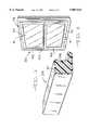
- FIG. 3is a perspective view of a composite member in the form of a window lineal made according to the method of the invention.
- FIG. 4is a perspective view of a double-hung window frame and sash constructed of window lineals in accordance with the invention.
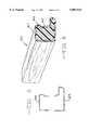
- FIG. 5is an enlarged sectional view in elevation of complementary wood veneer pieces suitable for combining as a carrier for an alternate embodiment of a window lineal.
- FIG. 6is a perspective view of a window lineal having a wood grain finish made using the wood veneer carrier of FIG. 5.
- a die or mold 11having the desired configuration of the composite member.
- a hollow carrier 12is positioned inside the die so that it takes the shape of the die.
- the carrierhas a cavity 13 and an inner surface 14.
- the carriercan be any material capable of forming the desired configuration of the composite member.
- the carriercan be a release paper such as silicone release paper, a release film, a decorative paper, a decorative plastic, or a combination of these materials.
- the carrieris a release material or other relatively non-rigid material, preferably the carrier is positioned inside a guide or die as shown to preserve the configuration until completion of the method.
- a dieis usually unnecessary when the carrier is a strong, rigid material such as a heavy vinyl.
- the carriercan be removed at the completion of the method, or it can be retained on the composite member as an outer layer such as a decorative facing.
- the methodcan be conducted without a release material or other carrier material by using the die as a carrier.
- the configuration of the carriercan be simple or complex depending on the configuration of the composite member.
- the carrieris a release paper in the complex shape of a window lineal which will be described below.
- the methodis very cost efficient because there is no waste of foam materials when making a complex shape.
- the cross-sectional shapecan be generally rectangular, round, or any other desired shape.
- the inner surface of the carriercan have a pattern such as a wood grain pattern which will be transferred to the resin when it is applied to the carrier.
- a curable resinis applied to the inner surface 14 of the carrier.
- the resinmay be in a liquid or gelled state.
- the resincan be applied in any manner, such as spraying or wiping, so that it lines the inner surface.
- the resinis applied by use of an injection apparatus 15.
- the apparatuscomprises a pair of elongated concentric tubes, which are preferably formed of metal.
- the outer tube having a closed endis a resin conduit 16 through which the resin is supplied.
- the resinis supplied under pressure by pumping it from a storage tank (not shown).
- the resinis a two-component material such as a polyurethane resin, the two components can be stored in separate tanks and combined in line immediately prior to application to the carrier.
- the resinmay be initially in a solid form and heated, e.g., in a storage tank, to liquefy it before application.
- a plurality of resin discharge outlets 17are positioned near the end of the resin conduit 16.
- the resin discharge outletsare formed around the circumference of the resin conduit so that resin 18 is discharged radially outward from the conduit onto the inner surface 14 of the carrier.
- the conduitincludes eight resin discharge outlets, two of which are shown.
- the resinis discharged by spraying it through the resin discharge outlets.
- the discharge rate and amountcan be adjusted using suitable means to obtain different resin thicknesses.
- the resinis applied so that the resulting resin skin has a thickness from about 0.5 mm to about 1 cm.
- the injection apparatus 15is inserted inside the cavity 13 so that the resin discharge outlets are positioned near one end of the carrier (the left end when viewing FIG. 1).
- the carriercan be stationary and the apparatus can move relative to the carrier as shown by the arrows in FIG. 1, or the apparatus can be stationary while the carrier moves as shown in FIG. 2.
- the resincan be selected from the group of structural thermoplastic and thermosetting resins.
- Polyurethanes, phenolics, polyesters, epoxies, vinyl esters, polyetherketones, polyetherimides, polyethersulphones, high-density polyethylenes (HDPEs), polycarbonates, acrylonitrile-butadiene-styrenes (ABSs), polypropylene (PPs), and nylonare, in general, suitable materials.
- the thermosetting polyestersare preferred due to their short cure time, relative chemical inertness and low cost.
- the resinis capable of curing to form a smooth skin and a hard finish on the finished composite member. Accelerating agents, compatabilizing agents, fillers, die release agents, second phases for toughening, and coloring agents can be added to the resin, as will be appreciated by those skilled in the art.
- a highly preferred resinis a polyurethane.
- This resinhas a short cure time at room temperature and it is readily sprayable.
- polyurethanesare produced by reacting an aromatic diisocyanate with a diol.
- An example of a preferred polyurethaneis produced by the catalyzed reaction of methylene diphenyl diisocyanate (MDI) with glycerol.
- MDImethylene diphenyl diisocyanate
- the injection apparatus 15further includes an inner tube which is a foam conduit 19.
- a curable foamis supplied through the foam conduit from any source.
- the foamis supplied by feeding a foamable material from a storage tank (not shown). If the foam is a two-component material such as a polyurethane foam, the two components can be stored in separate tanks and combined in-line immediately prior to introduction.
- the foam conduitincludes a foam discharge outlet 20 at its end for introduction of the foam into the carrier.
- the foam conduit 19extends a distance past the end of the resin conduit 16.
- the apparatusWhen the foam 21 is introduced into the cavity 13 of the carrier, the apparatus is further drawn through the cavity (to the right when viewing FIG. 1). Because of the construction of the apparatus, the resin 18 is applied to the inner surface of the cavity prior to introduction of the foam. As the resin cures, the foam is introduced and expands into contact with the resin. The foam contacts the resin when the resin is not more than partially cured, preferably not more than about 80% cured. The partially cured resin is not solidified and is still tacky. Preferably the foam contacts the resin when the resin has a viscosity not greater than about 250,000 centipoise at 25° C., and more preferably not greater than about 100,000 centipoise at 25° C., as measured according to ASTM C965.
- the foam and resincure together and form a continuous, intimate bond between the resin skin and the foam core of the composite member. If the resin were completely cured when contacted by the foam, the foam and resin would not form as good a bond.
- the resinis at least partially cured when the foam contacts it so that it adheres well to the inner surface of the carrier, and more preferably it has a viscosity of at least about 50,000 centipoise at 25° C.
- the foamcan be selected from any of the suitable foam materials known to persons skilled in the art.
- the foamcan be a high density structural-type foam or a low density insulation-type foam.
- the foamis selected from polyurethane foams, polyisocyanurate foams, phenolic foams, polyimide foams, epoxy foams, polyurea foams, polyolefin foams, polystyrene foams, and mixtures thereof.
- Polyurethane foams and polyisocyanurate foamsare most preferred because they rapidly cure at room temperature.
- Rigid polyurethane foamsare well known and are commonly prepared from organic polyisocyanates and organic polyols together with known blowing agents, surfactants, and catalysts. Phenolic foam is preferred for its low smoke generation in case of fire.
- one or more of a variety of chemical and physical blowing agentscan be used to expand the foam, including but not limited to water, carbon dioxide, non-fluorinated hydrocarbons, and fluorinated hydrocarbons such as HCFCs (i.e., hydrochlorofluorocarbons, e.g., dichlorofluoroethane (HCFC 141b) and chlorodifluoroethane (HCFC 142b)) and HFCs (i.e., hydrofluorocarbons, e.g., 1-fluoro-2-trifluoroethane (HFC 134a) and 1-difluoroethane (HFC 152a)).
- HCFCsi.e., hydrochlorofluorocarbons, e.g., dichlorofluoroethane (HCFC 141b) and chlorodifluoroethane (HCFC 142b)
- HFCsi.e., hydrofluorocarbons,
- fillerssuch as sawdust, corn husks, glass waste, or silica
- Additives and supplemental agentscan also be included, such as surfactants, catalysts, cell control agents, plasticizers, and fire retardants.
- the particular compositions of the foamsmay be selected from, e.g., known compositions, and the blending and mixing of the foam ingredients may be accomplished using means and techniques routinely selected by those skilled in the art.
- the composite memberis formed with a polyurethane resin skin and a polyurethane foam core.
- the resin and foamWhen the resin and foam are cured together, they react to form an intimate continuous bond due to the formation of urethane linkages between the isocyanates in the foam formulation and the polyols in the resin formulation, and vice-versa.
- the resin and foamare materials that can react with each other, curing the materials together allows the formation of covalent bonds.
- the bond formedis usually an interpenetrating network.
- a reinforcement material 22can be embedded in the resin skin.
- the reinforcement materialis usually positioned inside the carrier before applying the liquid resin. In such a case, the reinforcement material should be permeable to the liquid resin so that the resin penetrates the reinforcement material to the inner surface of the carrier.
- the reinforcement materialcan comprise any combination of rovings, mats, woven fabrics, or veils composed of fibers such as glass fibers, aramid fibers, carbon fibers, graphite fibers, or ceramic fibers.
- the reinforcement materialis a web made from polyester or glass fiber.
- FIG. 2illustrates a preferred continuous method of making a linear composite member in accordance with this invention, in which the injection apparatus is stationary and the carrier moves relative to the apparatus.
- a die 23is provided having the desired configuration of the composite member.
- Two sheets of a carrier 24such as a release film are pulled from upper and lower carrier rolls 25.
- the carrier sheetsare pulled through an opening of a former 26 which folds the sheets together so that they form the desired shape of the carrier.
- the carrieris then pulled around a mandrel 27 which shapes and positions the carrier for entering the die cavity 28.
- two sheets of a reinforcement material 29such as a glass fiber mat are pulled from upper and lower reinforcement material rolls 30, through the opening of the former and around the mandrel.
- the reinforcement material sheetsare positioned inside the carrier sheets to provide a structure of an outer carrier and a reinforcement material near the inner surface of the carrier.
- An injection apparatus 31like that illustrated in FIG. 1 is positioned through the former and the mandrel and extends into the die cavity. As the carrier and reinforcement material are pulled through the die cavity, the injection apparatus sprays a liquid resin onto the inner surface of the carrier and then introduces a foam inside the carrier. The resin is partially cured when it is contacted by the foam. The resin and foam are cured together inside the die to form a composite member 32 having a hard resin skin and a foam core. The composite member is pulled by any suitable traction or pulling device, such as traction drive 33. Subsequently, the composite member can be cut by any suitable means such as cutter 34 into desired lengths. A finish such as paint and a finish coat can be applied, if desired.
- FIG. 3illustrates a preferred composite member in the form of a window lineal 35 made according to the invention.
- the window linealincludes a foam core 36 and a hard resin skin 37 formed integral with the core.
- FIG. 4shows a window 38 in which a lineal such as illustrated in FIG. 3 can be incorporated.
- the windowincludes a generally rectangular frame 39. When installed in a building, the frame is stationary and positioned in an opening in a wall of the building.
- the frameis comprised of four linear or lineal members 40.
- the windowalso includes two generally rectangular sashes 41 positioned inside the frame. Each sash holds a pane 42 and is slidable up and down to open and close the window. Each sash is comprised of four linear or lineal members 43.
- FIGS. 5 and 6illustrate an alternate embodiment of a composite member in which the carrier is a wood shell such as a wood veneer which is retained as an outer surface on the composite member.
- the wood veneer surfaceis very attractive and thus desirable for use on building exteriors.
- Complementary first and second wood veneer pieces 44 and 45are assembled into a carrier similar to that shown in FIG. 1, or they can be pulled from rolls similar to the method shown in FIG. 2.
- a resinis applied to the inner surface of the carrier and a foam is introduced into the cavity of the carrier. The resin and foam cure together and form an intimate bond.
- the resultis a composite member in the form of a window lineal 46, having an outer surface 47 of wood veneer, a hard resin skin 48, and a foam core 49.
- a resin for use in the inventionis prepared by combining the following ingredients (in parts by weight):
- MDI75 methylene diphenyl diisocyanate
- the glycerol and catalystare mixed together at room temperature. Then the MDI is mixed with the glycerol and catalyst immediately prior to application of the resin.
- a foam for use in the inventionis prepared by combining the following ingredients (in parts by weight):
- Alkapol 770available from Rhone Poulenc, having a hydroxyl number of 770
- An alternate embodiment of a foamis prepared from the following ingredients (in parts by weight):
- Alkapol 6240available from Rhone Poulenc, having a hydroxyl number of 240
Landscapes
- Laminated Bodies (AREA)
- Casting Or Compression Moulding Of Plastics Or The Like (AREA)
Abstract
Description
Claims (15)
Priority Applications (7)
| Application Number | Priority Date | Filing Date | Title |
|---|---|---|---|
| US08/677,692US5807514A (en) | 1996-07-10 | 1996-07-10 | Manufacturing of foam-containing composites |
| KR1019980710789AKR20000022359A (en) | 1996-07-10 | 1997-07-07 | Manufacture of foam-containing composites |
| CA002259687ACA2259687A1 (en) | 1996-07-10 | 1997-07-07 | Manufacture of foam-containing composites |
| PCT/US1997/011936WO1998001279A1 (en) | 1996-07-10 | 1997-07-07 | Manufacture of foam-containing composites |
| EP97933342AEP0912313A4 (en) | 1996-07-10 | 1997-07-07 | Manufacture of foam-containing composites |
| JP10505340AJP2000514729A (en) | 1996-07-10 | 1997-07-07 | Method for producing composite with foam |
| US09/116,157US5955013A (en) | 1996-07-10 | 1998-07-16 | Manufacture of foam-containing structures |
Applications Claiming Priority (1)
| Application Number | Priority Date | Filing Date | Title |
|---|---|---|---|
| US08/677,692US5807514A (en) | 1996-07-10 | 1996-07-10 | Manufacturing of foam-containing composites |
Related Child Applications (1)
| Application Number | Title | Priority Date | Filing Date |
|---|---|---|---|
| US09/116,157Continuation-In-PartUS5955013A (en) | 1996-07-10 | 1998-07-16 | Manufacture of foam-containing structures |
Publications (1)
| Publication Number | Publication Date |
|---|---|
| US5807514Atrue US5807514A (en) | 1998-09-15 |
Family
ID=24719751
Family Applications (1)
| Application Number | Title | Priority Date | Filing Date |
|---|---|---|---|
| US08/677,692Expired - LifetimeUS5807514A (en) | 1996-07-10 | 1996-07-10 | Manufacturing of foam-containing composites |
Country Status (6)
| Country | Link |
|---|---|
| US (1) | US5807514A (en) |
| EP (1) | EP0912313A4 (en) |
| JP (1) | JP2000514729A (en) |
| KR (1) | KR20000022359A (en) |
| CA (1) | CA2259687A1 (en) |
| WO (1) | WO1998001279A1 (en) |
Cited By (35)
| Publication number | Priority date | Publication date | Assignee | Title |
|---|---|---|---|---|
| US5955013A (en)* | 1996-07-10 | 1999-09-21 | Owens Corning Fiberglas Technology, Inc. | Manufacture of foam-containing structures |
| US6265057B1 (en)* | 1997-03-17 | 2001-07-24 | The B. F. Goodrich Company | Ice protection system |
| US6352657B1 (en)* | 1996-12-13 | 2002-03-05 | 888804 Ontario Limited | Method and apparatus for making foam/concrete building panels |
| US20030031816A1 (en)* | 1999-12-18 | 2003-02-13 | Alfons Topp | Extrusion device and method for producing plastic hollow profiles having at least one hollow chamber space that is filled with foam |
| US20030052510A1 (en)* | 2001-08-22 | 2003-03-20 | Parat Automotive Schonenbach Gmbh + Co. Kg | Foldable convertible top and method of making same |
| US20040118580A1 (en)* | 2002-12-20 | 2004-06-24 | Commscope Properties, Llc | Method and apparatus for manufacturing coaxial cable with composite inner conductor |
| US20040175559A1 (en)* | 2000-03-22 | 2004-09-09 | Hume James M. | Liner for waste water system rehabilitation |
| US6863972B2 (en)* | 2001-01-09 | 2005-03-08 | Crane Plastics Company Llc | Synthetic wood component having a foamed polymer backing |
| US20050072087A1 (en)* | 2003-09-23 | 2005-04-07 | Fanucci Jerome P. | Joiner panel system |
| US6958185B1 (en) | 2000-07-31 | 2005-10-25 | Crane Plastics Company Llc | Multilayer synthetic wood component |
| US6971211B1 (en) | 1999-05-22 | 2005-12-06 | Crane Plastics Company Llc | Cellulosic/polymer composite material |
| US20060022376A1 (en)* | 2004-05-12 | 2006-02-02 | Prince Kendall W | Window covering parts and apparatus and methods for making the same |
| US7017352B2 (en) | 2001-01-19 | 2006-03-28 | Crane Plastics Company Llc | Cooling of extruded and compression molded materials |
| US20060113046A1 (en)* | 2004-05-12 | 2006-06-01 | Prince Kendall W | Stiffened parts for window covering and methods for making the same |
| US7296847B2 (en) | 2002-04-30 | 2007-11-20 | Zephyros, Inc. | Reinforcement system utilizing a hollow carrier |
| US20080187739A1 (en)* | 2007-01-16 | 2008-08-07 | Baker Charles H | Compositions for use as building materials, other molded items, and methods of and systems for making them |
| US20080302050A1 (en)* | 2007-02-05 | 2008-12-11 | Certainteed Corporation | Roofing tile with weather durable coloring matter |
| US20100116179A1 (en)* | 2008-10-15 | 2010-05-13 | Baker Charles H | Polyurethane composite matrix material and composite thereof |
| US7743567B1 (en) | 2006-01-20 | 2010-06-29 | The Crane Group Companies Limited | Fiberglass/cellulosic composite and method for molding |
| US20100173876A1 (en)* | 2000-12-19 | 2010-07-08 | The Board Of Regents Of The University Of Texas System | Oil-based nsaid compositions and methods for making and using same |
| US7875675B2 (en) | 2005-11-23 | 2011-01-25 | Milgard Manufacturing Incorporated | Resin for composite structures |
| US7901762B2 (en) | 2005-11-23 | 2011-03-08 | Milgard Manufacturing Incorporated | Pultruded component |
| US8074339B1 (en) | 2004-11-22 | 2011-12-13 | The Crane Group Companies Limited | Methods of manufacturing a lattice having a distressed appearance |
| US8101107B2 (en) | 2005-11-23 | 2012-01-24 | Milgard Manufacturing Incorporated | Method for producing pultruded components |
| US8167275B1 (en) | 2005-11-30 | 2012-05-01 | The Crane Group Companies Limited | Rail system and method for assembly |
| US20120276322A1 (en)* | 2011-04-27 | 2012-11-01 | Basf Se | Extruded plastics profiles comprising continuously introduced insulation elements |
| US8460797B1 (en) | 2006-12-29 | 2013-06-11 | Timbertech Limited | Capped component and method for forming |
| US8597016B2 (en) | 2005-11-23 | 2013-12-03 | Milgard Manufacturing Incorporated | System for producing pultruded components |
| US9303451B2 (en) | 2013-02-25 | 2016-04-05 | Precision Coating Innovations, Llc | System for pivoting a blind slat |
| USD780480S1 (en) | 2013-02-25 | 2017-03-07 | Precision Coating Innovations, L.L.C. | Low profile blind head rail |
| US9593222B2 (en) | 2013-05-14 | 2017-03-14 | Icp Adhesives And Sealants, Inc. | Method and composition for filling elongated channels with expanding foam insulation |
| DK201670806A1 (en)* | 2016-10-13 | 2018-04-23 | Vkr Holding As | A frame member, a method for making a frame member, a frame structure and use of a frame member |
| US20180273795A1 (en)* | 2005-07-26 | 2018-09-27 | Knauf Insulation, Inc. | Binders and materials made therewith |
| US20220267635A1 (en)* | 2005-07-26 | 2022-08-25 | Knauf Insulation, Inc. | Binders and materials made therewith |
| US20220314584A1 (en)* | 2021-03-31 | 2022-10-06 | Westlake Royal Building Products Inc. | Composite materials and methods of preparation thereof |
Families Citing this family (1)
| Publication number | Priority date | Publication date | Assignee | Title |
|---|---|---|---|---|
| AU1847499A (en)* | 1998-07-08 | 2000-02-03 | Universal Forme Cutting Pty Ltd | Improvements relating to gaskets and their manufacture |
Citations (21)
| Publication number | Priority date | Publication date | Assignee | Title |
|---|---|---|---|---|
| US3533901A (en)* | 1968-08-05 | 1970-10-13 | Allied Chem | Process for production of polyurethane foam laminates and product produced thereby |
| US3556888A (en)* | 1967-06-23 | 1971-01-19 | Glastrusions | Pultrusion machine and method |
| US3895087A (en)* | 1971-11-26 | 1975-07-15 | Champion Int Corp | Method of manufacturing a molded composite urethane foam structural panel |
| US3895896A (en)* | 1972-11-03 | 1975-07-22 | Pultrusions Corp | Apparatus for pultruding hollow objects |
| US3968561A (en)* | 1972-04-12 | 1976-07-13 | Thomas Francis Oakes | Method of fabricating hollow, foam-filled, metal structural members |
| JPS53147766A (en)* | 1977-05-31 | 1978-12-22 | Asahi Glass Co Ltd | Method of lining |
| US4576855A (en)* | 1982-07-22 | 1986-03-18 | Inoue Mtp Co., Ltd. | Coating composition and skinned polyurethane foam articles coated therewith |
| DE3438448A1 (en)* | 1984-10-19 | 1986-04-24 | Gebrüder Kömmerling Kunststoffwerke GmbH, 6780 Pirmasens | Plastics profile bar and process and crosshead die for the production thereof |
| JPS61125836A (en)* | 1984-11-26 | 1986-06-13 | Tachikawa Spring Co Ltd | Manufacture of urethane foamed product applied flock finishing |
| US4645710A (en)* | 1985-09-25 | 1987-02-24 | E. I. Du Pont De Nemours And Company | Foam laminate structures |
| US4773448A (en)* | 1987-02-26 | 1988-09-27 | Francis Norman L | Freeze-resistant plastic pipe and method for its manufacture |
| US4774794A (en)* | 1984-03-12 | 1988-10-04 | Grieb Donald J | Energy efficient building system |
| US5013508A (en)* | 1988-05-14 | 1991-05-07 | Guenther Troester | Method for producing elastomer skins as lining material for plastic molded articles such as automobile dashboards |
| US5106547A (en)* | 1988-12-12 | 1992-04-21 | Style-Mark, Inc. | Method for making a pre-formed millwork article |
| US5116557A (en)* | 1989-03-03 | 1992-05-26 | Recticel | Method of making objects having an elastomeric outer wall and a synthetic foam core |
| US5142835A (en)* | 1990-10-12 | 1992-09-01 | Taylor Building Products Company | Reaction injection molded door assembly |
| US5173227A (en)* | 1990-12-06 | 1992-12-22 | United Technologies Corporation | In-situ molding of fiber reinforced composites to net shape |
| US5286320A (en)* | 1991-11-18 | 1994-02-15 | Owens-Corning Fiberglas Technology Inc. | Method for making a pultruded panel |
| US5529731A (en)* | 1994-07-13 | 1996-06-25 | Caine Corporation | Method of making an elongate composite structural member |
| US5608957A (en)* | 1995-01-25 | 1997-03-11 | Hanagan; Michael W. | Method of making a motorcycle seat |
| US5653923A (en)* | 1996-02-29 | 1997-08-05 | Owens-Corning Fiberglas Technology, Inc. | Method for making shaped members using a foam froth |
- 1996
- 1996-07-10USUS08/677,692patent/US5807514A/ennot_activeExpired - Lifetime
- 1997
- 1997-07-07EPEP97933342Apatent/EP0912313A4/ennot_activeWithdrawn
- 1997-07-07JPJP10505340Apatent/JP2000514729A/enactivePending
- 1997-07-07KRKR1019980710789Apatent/KR20000022359A/ennot_activeCeased
- 1997-07-07WOPCT/US1997/011936patent/WO1998001279A1/ennot_activeApplication Discontinuation
- 1997-07-07CACA002259687Apatent/CA2259687A1/ennot_activeAbandoned
Patent Citations (21)
| Publication number | Priority date | Publication date | Assignee | Title |
|---|---|---|---|---|
| US3556888A (en)* | 1967-06-23 | 1971-01-19 | Glastrusions | Pultrusion machine and method |
| US3533901A (en)* | 1968-08-05 | 1970-10-13 | Allied Chem | Process for production of polyurethane foam laminates and product produced thereby |
| US3895087A (en)* | 1971-11-26 | 1975-07-15 | Champion Int Corp | Method of manufacturing a molded composite urethane foam structural panel |
| US3968561A (en)* | 1972-04-12 | 1976-07-13 | Thomas Francis Oakes | Method of fabricating hollow, foam-filled, metal structural members |
| US3895896A (en)* | 1972-11-03 | 1975-07-22 | Pultrusions Corp | Apparatus for pultruding hollow objects |
| JPS53147766A (en)* | 1977-05-31 | 1978-12-22 | Asahi Glass Co Ltd | Method of lining |
| US4576855A (en)* | 1982-07-22 | 1986-03-18 | Inoue Mtp Co., Ltd. | Coating composition and skinned polyurethane foam articles coated therewith |
| US4774794A (en)* | 1984-03-12 | 1988-10-04 | Grieb Donald J | Energy efficient building system |
| DE3438448A1 (en)* | 1984-10-19 | 1986-04-24 | Gebrüder Kömmerling Kunststoffwerke GmbH, 6780 Pirmasens | Plastics profile bar and process and crosshead die for the production thereof |
| JPS61125836A (en)* | 1984-11-26 | 1986-06-13 | Tachikawa Spring Co Ltd | Manufacture of urethane foamed product applied flock finishing |
| US4645710A (en)* | 1985-09-25 | 1987-02-24 | E. I. Du Pont De Nemours And Company | Foam laminate structures |
| US4773448A (en)* | 1987-02-26 | 1988-09-27 | Francis Norman L | Freeze-resistant plastic pipe and method for its manufacture |
| US5013508A (en)* | 1988-05-14 | 1991-05-07 | Guenther Troester | Method for producing elastomer skins as lining material for plastic molded articles such as automobile dashboards |
| US5106547A (en)* | 1988-12-12 | 1992-04-21 | Style-Mark, Inc. | Method for making a pre-formed millwork article |
| US5116557A (en)* | 1989-03-03 | 1992-05-26 | Recticel | Method of making objects having an elastomeric outer wall and a synthetic foam core |
| US5142835A (en)* | 1990-10-12 | 1992-09-01 | Taylor Building Products Company | Reaction injection molded door assembly |
| US5173227A (en)* | 1990-12-06 | 1992-12-22 | United Technologies Corporation | In-situ molding of fiber reinforced composites to net shape |
| US5286320A (en)* | 1991-11-18 | 1994-02-15 | Owens-Corning Fiberglas Technology Inc. | Method for making a pultruded panel |
| US5529731A (en)* | 1994-07-13 | 1996-06-25 | Caine Corporation | Method of making an elongate composite structural member |
| US5608957A (en)* | 1995-01-25 | 1997-03-11 | Hanagan; Michael W. | Method of making a motorcycle seat |
| US5653923A (en)* | 1996-02-29 | 1997-08-05 | Owens-Corning Fiberglas Technology, Inc. | Method for making shaped members using a foam froth |
Cited By (52)
| Publication number | Priority date | Publication date | Assignee | Title |
|---|---|---|---|---|
| US5955013A (en)* | 1996-07-10 | 1999-09-21 | Owens Corning Fiberglas Technology, Inc. | Manufacture of foam-containing structures |
| US6352657B1 (en)* | 1996-12-13 | 2002-03-05 | 888804 Ontario Limited | Method and apparatus for making foam/concrete building panels |
| US6265057B1 (en)* | 1997-03-17 | 2001-07-24 | The B. F. Goodrich Company | Ice protection system |
| US6971211B1 (en) | 1999-05-22 | 2005-12-06 | Crane Plastics Company Llc | Cellulosic/polymer composite material |
| US6881365B2 (en)* | 1999-12-18 | 2005-04-19 | Veka Ag | Extrusion device and method for producing plastic hollow profiles having at least one hollow chamber space that is filled with foam |
| US20030031816A1 (en)* | 1999-12-18 | 2003-02-13 | Alfons Topp | Extrusion device and method for producing plastic hollow profiles having at least one hollow chamber space that is filled with foam |
| US7279196B2 (en)* | 2000-03-22 | 2007-10-09 | Hume James M | Liner for waste water system rehabilitation |
| US20040175559A1 (en)* | 2000-03-22 | 2004-09-09 | Hume James M. | Liner for waste water system rehabilitation |
| US6958185B1 (en) | 2000-07-31 | 2005-10-25 | Crane Plastics Company Llc | Multilayer synthetic wood component |
| US20100173876A1 (en)* | 2000-12-19 | 2010-07-08 | The Board Of Regents Of The University Of Texas System | Oil-based nsaid compositions and methods for making and using same |
| US6863972B2 (en)* | 2001-01-09 | 2005-03-08 | Crane Plastics Company Llc | Synthetic wood component having a foamed polymer backing |
| US7017352B2 (en) | 2001-01-19 | 2006-03-28 | Crane Plastics Company Llc | Cooling of extruded and compression molded materials |
| US6818279B2 (en)* | 2001-08-22 | 2004-11-16 | Parat Automotive Schonenbach Gmbh & Co. Kg | Foldable convertible top and method of making same |
| US20030052510A1 (en)* | 2001-08-22 | 2003-03-20 | Parat Automotive Schonenbach Gmbh + Co. Kg | Foldable convertible top and method of making same |
| US8128780B2 (en) | 2002-04-30 | 2012-03-06 | Zephyros, Inc. | Reinforcement system utilizing a hollow carrier |
| US7296847B2 (en) | 2002-04-30 | 2007-11-20 | Zephyros, Inc. | Reinforcement system utilizing a hollow carrier |
| US20040118580A1 (en)* | 2002-12-20 | 2004-06-24 | Commscope Properties, Llc | Method and apparatus for manufacturing coaxial cable with composite inner conductor |
| US6915564B2 (en) | 2002-12-20 | 2005-07-12 | Commscope Properties Llc | Method and apparatus for manufacturing coaxial cable with composite inner conductor |
| US20050072087A1 (en)* | 2003-09-23 | 2005-04-07 | Fanucci Jerome P. | Joiner panel system |
| US7811493B2 (en)* | 2003-09-23 | 2010-10-12 | Kazak Composites, Incorporated | Joiner panel system |
| US20060022376A1 (en)* | 2004-05-12 | 2006-02-02 | Prince Kendall W | Window covering parts and apparatus and methods for making the same |
| US20060113046A1 (en)* | 2004-05-12 | 2006-06-01 | Prince Kendall W | Stiffened parts for window covering and methods for making the same |
| US8074339B1 (en) | 2004-11-22 | 2011-12-13 | The Crane Group Companies Limited | Methods of manufacturing a lattice having a distressed appearance |
| US20220267635A1 (en)* | 2005-07-26 | 2022-08-25 | Knauf Insulation, Inc. | Binders and materials made therewith |
| US20180273795A1 (en)* | 2005-07-26 | 2018-09-27 | Knauf Insulation, Inc. | Binders and materials made therewith |
| US7875675B2 (en) | 2005-11-23 | 2011-01-25 | Milgard Manufacturing Incorporated | Resin for composite structures |
| US7901762B2 (en) | 2005-11-23 | 2011-03-08 | Milgard Manufacturing Incorporated | Pultruded component |
| US8597016B2 (en) | 2005-11-23 | 2013-12-03 | Milgard Manufacturing Incorporated | System for producing pultruded components |
| US8101107B2 (en) | 2005-11-23 | 2012-01-24 | Milgard Manufacturing Incorporated | Method for producing pultruded components |
| US8519050B2 (en) | 2005-11-23 | 2013-08-27 | Milgard Manufacturing Incorporated | Resin for composite structures |
| US10358841B2 (en) | 2005-11-30 | 2019-07-23 | Cpg International Llc | Rail system and method for assembly |
| US9822547B2 (en) | 2005-11-30 | 2017-11-21 | Cpg International Llc | Rail system and method for assembly |
| US8167275B1 (en) | 2005-11-30 | 2012-05-01 | The Crane Group Companies Limited | Rail system and method for assembly |
| USD782697S1 (en) | 2005-11-30 | 2017-03-28 | Cpg International Llc | Rail |
| USD797953S1 (en) | 2005-11-30 | 2017-09-19 | Cpg International Llc | Rail assembly |
| USD797307S1 (en) | 2005-11-30 | 2017-09-12 | Cpg International Llc | Rail assembly |
| USD788329S1 (en) | 2005-11-30 | 2017-05-30 | Cpg International Llc | Post cover |
| USD787707S1 (en) | 2005-11-30 | 2017-05-23 | Cpg International Llc | Rail |
| USD782698S1 (en) | 2005-11-30 | 2017-03-28 | Cpg International Llc | Rail |
| US7743567B1 (en) | 2006-01-20 | 2010-06-29 | The Crane Group Companies Limited | Fiberglass/cellulosic composite and method for molding |
| US8460797B1 (en) | 2006-12-29 | 2013-06-11 | Timbertech Limited | Capped component and method for forming |
| US20080187739A1 (en)* | 2007-01-16 | 2008-08-07 | Baker Charles H | Compositions for use as building materials, other molded items, and methods of and systems for making them |
| US9493952B2 (en)* | 2007-02-05 | 2016-11-15 | Certainteed Corporation | Roofing tile with weather durable coloring matter |
| US20080302050A1 (en)* | 2007-02-05 | 2008-12-11 | Certainteed Corporation | Roofing tile with weather durable coloring matter |
| US20100116179A1 (en)* | 2008-10-15 | 2010-05-13 | Baker Charles H | Polyurethane composite matrix material and composite thereof |
| US9492957B2 (en)* | 2011-04-27 | 2016-11-15 | Basf Se | Extruded plastics profiles comprising continuously introduced insulation elements |
| US20120276322A1 (en)* | 2011-04-27 | 2012-11-01 | Basf Se | Extruded plastics profiles comprising continuously introduced insulation elements |
| USD780480S1 (en) | 2013-02-25 | 2017-03-07 | Precision Coating Innovations, L.L.C. | Low profile blind head rail |
| US9303451B2 (en) | 2013-02-25 | 2016-04-05 | Precision Coating Innovations, Llc | System for pivoting a blind slat |
| US9593222B2 (en) | 2013-05-14 | 2017-03-14 | Icp Adhesives And Sealants, Inc. | Method and composition for filling elongated channels with expanding foam insulation |
| DK201670806A1 (en)* | 2016-10-13 | 2018-04-23 | Vkr Holding As | A frame member, a method for making a frame member, a frame structure and use of a frame member |
| US20220314584A1 (en)* | 2021-03-31 | 2022-10-06 | Westlake Royal Building Products Inc. | Composite materials and methods of preparation thereof |
Also Published As
| Publication number | Publication date |
|---|---|
| WO1998001279A1 (en) | 1998-01-15 |
| KR20000022359A (en) | 2000-04-25 |
| JP2000514729A (en) | 2000-11-07 |
| EP0912313A4 (en) | 1999-07-07 |
| EP0912313A1 (en) | 1999-05-06 |
| CA2259687A1 (en) | 1998-01-15 |
Similar Documents
| Publication | Publication Date | Title |
|---|---|---|
| US5807514A (en) | Manufacturing of foam-containing composites | |
| US5955013A (en) | Manufacture of foam-containing structures | |
| US5653923A (en) | Method for making shaped members using a foam froth | |
| CA1205368A (en) | Structural laminate and method for making same | |
| US5142835A (en) | Reaction injection molded door assembly | |
| US4130614A (en) | Method for making structural foams with facing sheets | |
| US2855021A (en) | Process for producing plates, sheels and shaped elements | |
| US3903346A (en) | Polyisocyanurate structural laminate and process for producing same | |
| US20070110979A1 (en) | Fiber-reinforced composite fire door | |
| US3792141A (en) | Method of structural fabrication | |
| US4372900A (en) | Method of forming reinforced foam structure | |
| US4938819A (en) | Method of making a composite panel of a foam material | |
| US20070193677A1 (en) | Method for manufacturing composite foam products | |
| CN100584587C (en) | Process for the production of polyurethane molded articles | |
| US4386983A (en) | Method of making a foam structural laminate | |
| CN102066859A (en) | Units insulated with foams and having flexible outer skins | |
| US20160138267A1 (en) | Polyurethane foam building members for residential and/or commercial buildings | |
| US4346133A (en) | Structural laminate and method for making same | |
| CN113462145A (en) | Fiber-reinforced polyurethane wood-like material and forming method thereof | |
| US20050260400A1 (en) | Foam products with silane impregnated facer | |
| GB2032570A (en) | Method for the repair of damaged surfaces | |
| MXPA01000530A (en) | Manufacture of foam-containing structures | |
| JPH06285885A (en) | Extraction molding method of composite body | |
| JPH0649297B2 (en) | Flame-retardant heat insulating material and manufacturing method thereof | |
| JP2002052617A (en) | Method for manufacturing fiber reinforced composite material |
Legal Events
| Date | Code | Title | Description |
|---|---|---|---|
| AS | Assignment | Owner name:OWENS-CORNING FIBERGLAS TECHNOLOGY, INC., ILLINOIS Free format text:ASSIGNMENT OF ASSIGNORS INTEREST;ASSIGNORS:GRINSHPUN, VYACHESLAV S.;SPOO, KEVIN J.;HULLS, BYRON;REEL/FRAME:008114/0504;SIGNING DATES FROM 19960709 TO 19960710 | |
| STCF | Information on status: patent grant | Free format text:PATENTED CASE | |
| FEPP | Fee payment procedure | Free format text:PAYOR NUMBER ASSIGNED (ORIGINAL EVENT CODE: ASPN); ENTITY STATUS OF PATENT OWNER: LARGE ENTITY | |
| FPAY | Fee payment | Year of fee payment:4 | |
| REMI | Maintenance fee reminder mailed | ||
| FPAY | Fee payment | Year of fee payment:8 | |
| AS | Assignment | Owner name:OWENS CORNING INTELLECTUAL CAPITAL, LLC, OHIO Free format text:ASSIGNMENT OF ASSIGNORS INTEREST;ASSIGNOR:OWENS-CORNING FIBERGLASS TECHNOLOGY, INC.;REEL/FRAME:019795/0433 Effective date:20070803 Owner name:OWENS CORNING INTELLECTUAL CAPITAL, LLC,OHIO Free format text:ASSIGNMENT OF ASSIGNORS INTEREST;ASSIGNOR:OWENS-CORNING FIBERGLASS TECHNOLOGY, INC.;REEL/FRAME:019795/0433 Effective date:20070803 Owner name:OWENS CORNING INTELLECTUAL CAPITAL, LLC, OHIO Free format text:ASSIGNMENT OF ASSIGNORS INTEREST;ASSIGNOR:OWENS-CORNING FIBERGLAS TECHNOLOGY, INC.;REEL/FRAME:019795/0433 Effective date:20070803 | |
| FPAY | Fee payment | Year of fee payment:12 |