US5807075A - Disposable ambulatory microprocessor controlled volumetric pump - Google Patents
Disposable ambulatory microprocessor controlled volumetric pumpDownload PDFInfo
- Publication number
- US5807075A US5807075AUS08/643,472US64347296AUS5807075AUS 5807075 AUS5807075 AUS 5807075AUS 64347296 AUS64347296 AUS 64347296AUS 5807075 AUS5807075 AUS 5807075A
- Authority
- US
- United States
- Prior art keywords
- pump
- channel
- fluid
- disposed
- membrane
- Prior art date
- Legal status (The legal status is an assumption and is not a legal conclusion. Google has not performed a legal analysis and makes no representation as to the accuracy of the status listed.)
- Expired - Lifetime
Links
Images


Classifications
- F—MECHANICAL ENGINEERING; LIGHTING; HEATING; WEAPONS; BLASTING
- F04—POSITIVE - DISPLACEMENT MACHINES FOR LIQUIDS; PUMPS FOR LIQUIDS OR ELASTIC FLUIDS
- F04B—POSITIVE-DISPLACEMENT MACHINES FOR LIQUIDS; PUMPS
- F04B7/00—Piston machines or pumps characterised by having positively-driven valving
- F04B7/0003—Piston machines or pumps characterised by having positively-driven valving the distribution member forming both the inlet and discharge distributor for one single pumping chamber
- F04B7/0015—Piston machines or pumps characterised by having positively-driven valving the distribution member forming both the inlet and discharge distributor for one single pumping chamber and having a slidable movement
- A—HUMAN NECESSITIES
- A61—MEDICAL OR VETERINARY SCIENCE; HYGIENE
- A61M—DEVICES FOR INTRODUCING MEDIA INTO, OR ONTO, THE BODY; DEVICES FOR TRANSDUCING BODY MEDIA OR FOR TAKING MEDIA FROM THE BODY; DEVICES FOR PRODUCING OR ENDING SLEEP OR STUPOR
- A61M5/00—Devices for bringing media into the body in a subcutaneous, intra-vascular or intramuscular way; Accessories therefor, e.g. filling or cleaning devices, arm-rests
- A61M5/14—Infusion devices, e.g. infusing by gravity; Blood infusion; Accessories therefor
- A61M5/142—Pressure infusion, e.g. using pumps
- F—MECHANICAL ENGINEERING; LIGHTING; HEATING; WEAPONS; BLASTING
- F04—POSITIVE - DISPLACEMENT MACHINES FOR LIQUIDS; PUMPS FOR LIQUIDS OR ELASTIC FLUIDS
- F04B—POSITIVE-DISPLACEMENT MACHINES FOR LIQUIDS; PUMPS
- F04B17/00—Pumps characterised by combination with, or adaptation to, specific driving engines or motors
- F04B17/03—Pumps characterised by combination with, or adaptation to, specific driving engines or motors driven by electric motors
- F—MECHANICAL ENGINEERING; LIGHTING; HEATING; WEAPONS; BLASTING
- F04—POSITIVE - DISPLACEMENT MACHINES FOR LIQUIDS; PUMPS FOR LIQUIDS OR ELASTIC FLUIDS
- F04B—POSITIVE-DISPLACEMENT MACHINES FOR LIQUIDS; PUMPS
- F04B49/00—Control, e.g. of pump delivery, or pump pressure of, or safety measures for, machines, pumps, or pumping installations, not otherwise provided for, or of interest apart from, groups F04B1/00 - F04B47/00
- F04B49/12—Control, e.g. of pump delivery, or pump pressure of, or safety measures for, machines, pumps, or pumping installations, not otherwise provided for, or of interest apart from, groups F04B1/00 - F04B47/00 by varying the length of stroke of the working members
- F—MECHANICAL ENGINEERING; LIGHTING; HEATING; WEAPONS; BLASTING
- F04—POSITIVE - DISPLACEMENT MACHINES FOR LIQUIDS; PUMPS FOR LIQUIDS OR ELASTIC FLUIDS
- F04B—POSITIVE-DISPLACEMENT MACHINES FOR LIQUIDS; PUMPS
- F04B53/00—Component parts, details or accessories not provided for in, or of interest apart from, groups F04B1/00 - F04B23/00 or F04B39/00 - F04B47/00
- F04B53/02—Packing the free space between cylinders and pistons
- F—MECHANICAL ENGINEERING; LIGHTING; HEATING; WEAPONS; BLASTING
- F04—POSITIVE - DISPLACEMENT MACHINES FOR LIQUIDS; PUMPS FOR LIQUIDS OR ELASTIC FLUIDS
- F04B—POSITIVE-DISPLACEMENT MACHINES FOR LIQUIDS; PUMPS
- F04B53/00—Component parts, details or accessories not provided for in, or of interest apart from, groups F04B1/00 - F04B23/00 or F04B39/00 - F04B47/00
- F04B53/16—Casings; Cylinders; Cylinder liners or heads; Fluid connections
- F04B53/162—Adaptations of cylinders
- F04B53/164—Stoffing boxes
- F—MECHANICAL ENGINEERING; LIGHTING; HEATING; WEAPONS; BLASTING
- F04—POSITIVE - DISPLACEMENT MACHINES FOR LIQUIDS; PUMPS FOR LIQUIDS OR ELASTIC FLUIDS
- F04B—POSITIVE-DISPLACEMENT MACHINES FOR LIQUIDS; PUMPS
- F04B9/00—Piston machines or pumps characterised by the driving or driven means to or from their working members
- F04B9/02—Piston machines or pumps characterised by the driving or driven means to or from their working members the means being mechanical
- F04B9/04—Piston machines or pumps characterised by the driving or driven means to or from their working members the means being mechanical the means being cams, eccentrics or pin-and-slot mechanisms
- F04B9/045—Piston machines or pumps characterised by the driving or driven means to or from their working members the means being mechanical the means being cams, eccentrics or pin-and-slot mechanisms the means being eccentrics
- F—MECHANICAL ENGINEERING; LIGHTING; HEATING; WEAPONS; BLASTING
- F16—ENGINEERING ELEMENTS AND UNITS; GENERAL MEASURES FOR PRODUCING AND MAINTAINING EFFECTIVE FUNCTIONING OF MACHINES OR INSTALLATIONS; THERMAL INSULATION IN GENERAL
- F16K—VALVES; TAPS; COCKS; ACTUATING-FLOATS; DEVICES FOR VENTING OR AERATING
- F16K41/00—Spindle sealings
- F16K41/10—Spindle sealings with diaphragm, e.g. shaped as bellows or tube
- F16K41/12—Spindle sealings with diaphragm, e.g. shaped as bellows or tube with approximately flat diaphragm
- F—MECHANICAL ENGINEERING; LIGHTING; HEATING; WEAPONS; BLASTING
- F04—POSITIVE - DISPLACEMENT MACHINES FOR LIQUIDS; PUMPS FOR LIQUIDS OR ELASTIC FLUIDS
- F04B—POSITIVE-DISPLACEMENT MACHINES FOR LIQUIDS; PUMPS
- F04B2201/00—Pump parameters
- F04B2201/12—Parameters of driving or driven means
- F04B2201/1208—Angular position of the shaft
- F—MECHANICAL ENGINEERING; LIGHTING; HEATING; WEAPONS; BLASTING
- F04—POSITIVE - DISPLACEMENT MACHINES FOR LIQUIDS; PUMPS FOR LIQUIDS OR ELASTIC FLUIDS
- F04B—POSITIVE-DISPLACEMENT MACHINES FOR LIQUIDS; PUMPS
- F04B2205/00—Fluid parameters
- F04B2205/05—Pressure after the pump outlet
- F—MECHANICAL ENGINEERING; LIGHTING; HEATING; WEAPONS; BLASTING
- F05—INDEXING SCHEMES RELATING TO ENGINES OR PUMPS IN VARIOUS SUBCLASSES OF CLASSES F01-F04
- F05C—INDEXING SCHEME RELATING TO MATERIALS, MATERIAL PROPERTIES OR MATERIAL CHARACTERISTICS FOR MACHINES, ENGINES OR PUMPS OTHER THAN NON-POSITIVE-DISPLACEMENT MACHINES OR ENGINES
- F05C2225/00—Synthetic polymers, e.g. plastics; Rubber
- F05C2225/04—PTFE [PolyTetraFluorEthylene]
Definitions
- This inventionrelates to a lightweight, inexpensive ambulatory volumetric pump, suitable for a variety of uses including medical systems such as intravenous (IV) therapy systems and the like.
- IVintravenous
- the intravenous administration of fluids to patientsis a well-known medical procedure for, among other things, administering life sustaining nutrients to patients whose digestive tracts are unable to function normally due to illness or injury, administering antibiotics to treat a variety of serious infections, administering analgesic drugs to patients suffering from acute or chronic pain, administering chemotherapy drugs to treat patients suffering from cancer, etc.
- IV administration setincluding, for example, a bottle of fluid to be administered and typically positioned upside down, a sterile plastic tubing set, and a pump for pumping fluid from the bottle through the IV set to the patient.
- Other mechanismsmay be included to manually stop the flow of fluid to the IV feeding tube and possibly some monitoring devices.
- Current IV pumpsgenerally are of two basic types: electronic pumps and disposable non-electronic pumps. Although the electronic pumps have been significantly miniaturized and do include some disposable components, they are nevertheless generally high in cost, require frequent maintenance with continued use, and may be difficult for a layman to operate if, for example, self treatment is desired.
- the disposable non-electric pumpsgenerally consist of small elastomeric bags within a hard shell container, in which the bags are filled with IV solution under pressure.
- the pressure generated by the contraction of the elastomeric bagforces the IV solution through a fixed orifice at a constant flow rate into the patient's vein.
- an ambulatory volumetric pumpwhich includes a housing in which is defined a channel having an inlet for receiving a fluid and an outlet for discharging the fluid. Also disposed in the housing is a pump operable to pump fluid through the channel, a motor for operating the pump in response to control signals, and a programmable controller for selectively supplying control signals to the motor to cause the motor to operate and pump fluid, either intermittently or continuously.
- the programmable controlleris provided with rotatable knobs which are exposed and accessible through the housing and which, when rotated to selected positions, both establish the operating parameters for the pump and display for viewing what the selected parameters are.
- the housingincludes a base housing in which are disposed the motor and programmable controller, a casing in which is defined and disposed respectively the channel and the pump, and a clip mechanism to enable clipping the casing onto the base housing.
- the motorincludes the drive gear exposed through a wall of the base housing and the pump includes a drive hub engageable with the drive gear, to be driven thereby, when the casing is clipped onto the base housing.
- the pumputilizes a simple circumferential polymeric seal, or sphincter seal, to retain and prevent loss or leaking of fluid being pumped.
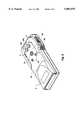
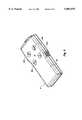
- FIG. 1is a top perspective view of an ambulatory, volumetric pump made in accordance with the principles of the present invention
- FIG. 2is a top, perspective view of the base housing of the pump of the present invention
- FIG. 3is a bottom perspective view of the base housing
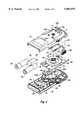
- FIG. 4is an exploded view of the base housing and components contained therein;
- FIG. 5is a bottom perspective view of the cassette of the pump of the present invention.
- FIG. 6is a top exploded view of the cassette
- FIG. 7is a bottom exploded view of the cassette
- FIG. 8is a side, cross-sectional view of the cassette mounted on the base housing, showing various components
- FIGS. 9A and 9Bare side, cross-sectional views of the pump of the present invention, showing a flow control valve in the open position and closed position respectively;
- FIGS. 10A-10Eshow different views of an illustrative embodiment of a face drive gear suitable for use in the present invention
- FIGS. 11A and 11Bare perspective views of drive and driven hubs by which the motor operates the pump in the present invention.
- FIG. 12is a fragmented, side graphic representation of the motor drive shaft and pinion gear, and face drive gear of the present invention.
- FIG. 13is a fragmented, side cross-sectional view of the face gear spindle and support gear cup used in the present invention.
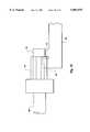
- FIG. 14is a fragmented, side cross-sectional view of an illustrative capillary labyrinth seal used in the present invention.
- FIG. 15is a fragmented, side cross-sectional view of the piston sphincter seal of the present invention.
- FIG. 16is a schematic view of the flow channel, pump, valves, pressure sensors, and filters of the present invention.
- FIG. 1is a top, perspective view of one illustrative embodiment of an ambulatory microprocessor-controlled volumetric pump having a base housing 4 in which are disposed pump driver components of the invention, including an electric motor, battery power source, and programmable microprocessor for controlling the pumping operation.
- a cassette (or casing) 8Detachably mounted on the base housing 4 is a cassette (or casing) 8 in which are contained the pump mechanism, a channel through which a fluid to be delivered to a patient is pumped, and valves for controlling the flow of fluid.
- An inlet tube 12is coupled to the cassette 8 to carry fluid from a source to the channel in the cassette, and an outlet tube 16 is also coupled to the cassette to carry fluid from the channel to a destination as a result of the operation of the pumping mechanism.
- a run/stop switch 20by which a patient may activate the programmable microprocessor.
- the cassette 8is held in place on the base housing 4 by a pair of mounting clips 24 (see also FIG. 5) which deflect outwardly after the cassette 8 is pressed into position on the base housing 4.
- a pair of mounting clips 24see also FIG. 5
- tabs 24aFIG. 5
- the mounting clips 24are pressed inwardly to deflect the tabs 24a inwardly, thus pulling them from the slots 6.
- the cassette 8can then be removed.
- FIG. 2shows a top perspective view of the base housing 4, with the cassette removed to expose the recess 28 formed in the upper wall 4a of the base housing for receiving the cassette.
- Protruding through openings in the upper wall 4a of the base housing 4are pressure sensor buttons 32a and 32b (to be discussed later), a face drive gear 72 (also to be discussed later), and valve actuator lever pins 40 which, as will be explained later, cause the selective opening and closing of valves located in the channel formed in the cassette to either allow or prevent the flow of fluid therethrough.
- FIG. 3is a perspective view of the bottom of the base housing 4 showing four rotatable knobs 44a, 44b, 44c and 44d which are exposed through a bottom wall 4b of the housing.
- the tops of the knobs 44a through 44dare substantially flush with the bottom wall 4b so that clothing or other items will not snag on the knobs and so that the knobs won't be inadvertently moved by bumping, etc.
- Formed in the top surfaces of the knobs 44a through 44dare recesses in the shape of arrows and into which a coin, fingernail, screw driver or other tool may be inserted to rotate the knobs to a desired position.
- the knobsare used to "program" a programmable microprocessor contained in the base housing 4, to operate the pump according to the parameter settings of the knobs. In other words, the rotary or angular position of each knob establishes a particular parameter of operation of the pump such as flow rate, number of doses or pump cycles over some period of time, the total dosage time, total volume of fluid to be pumped, etc.
- Communication of the knob settings to the programmable microprocessorcould be carried out in a variety of ways including provision of metal, conductive wipers on the underside of the knobs to press against copper patterns on a printed circuit board 94 (FIG. 4) contained in the base housing 4 in such a way that binary coded signals or bits can be read from the position of the wipers on the copper patterns by the programmable microprocessor.
- knobs 44a, 44b, 44c and 44dalso provides a visual display of the parameters chosen by reason of the direction in which the recessed arrows are pointing. Labels disposed around the knobs could identify the parametric values for the various rotary positions of the knobs.
- Brackets 50are formed in the bottom wall 4b for receiving and holding batteries 54 and 58 which are the power source for operating the programmable microprocessor 59 and motor which causes operation of the pump.
- Brackets 60are also formed in the bottom wall 4b for receiving and holding a miniature electric motor 64.
- a motor drive shaft 68(and pinion gear) extends forwardly of the motor 64 to engage and cause a face drive gear 72 to rotate when the motor 64 is operated.
- FIG. 12shows a fragmented, cross-sectional view of a portion of the motor drive shaft 68 on the end of which is mounted a pinion gear 76 with a roller extension 78.
- the pinion gear teethmesh with gear teeth 80 formed at the edge of the face drive gear 72 to extend axially thereof, as seen in FIG. 12.
- Formed inside the face gear teeth 80 to extend circumferentially on the face drive gear 72is an annular bead 84 over which the roller 78 rolls, as the motor drive shaft 68 rotates to thus rotate the pinion gear and cause the face drive gear to rotate.
- the face drive gear 72is shown in greater detail in FIGS. 10A-10E.
- the gear 72includes a disk 82 on the outer edge of which are formed the gear teeth 80 on the underside thereof, as best seen in FIGS. 10D and 10E.
- the annular bead 84is located just inside (but could be outside) the gear teeth 80.
- a central recess 86is formed on the underside of the disk 82 and a spindle 88 extends downwardly from the recess 86 (FIG. 10C) to terminate generally in a spherical tip 88a.
- the spindle 88rotatably supports the face drive gear 72 in a bearing cup 90 which is disposed on the bottom wall 4b of the base housing 4 (FIG. 4).
- the spindle 88 of the face drive gear 72extends through an opening in a circuit board 94 to the bearing cup 90 to enable rotation of the face drive gear.
- FIG. 13shows a side, cross-sectional view of the lower end of the spindle 88 and tip 88a disposed in the bearing cup 90.
- Side walls 90a of the bearing cup 90are in the shape of an inverted cone so that the contact surface between the spherical tip 88a and the side walls 90a is small, and this reduces friction in the rotation of the face drive gear 72 and thus reduces power consumption in the operation of the pump. Other features of the face drive gear 72 will be discussed later.
- FIG. 4there are shown four programming disks 100, each of which is coupled to a respective programming knob so as to be rotated when the knob is rotated and thus allow for developing different electrical contact patterns with electrical contacts on the underside of the circuit board 94.
- These electrical contact pointsare disposed so that when electrical contacts 100a on the disks 100 contact different ones of the contact points, different settings for the programming knobs can be detected by the microprocessor 59.
- the circuit board 94is mounted on the bottom wall 4b of the base housing 4 and, as earlier indicated, the programmable microprocessor 59 for controlling operation of the pump is mounted on the circuit board as is other circuitry for carrying signals to and from the microprocessor.
- a cam track 74Formed in the top surface of the face drive gear 72 is a cam track 74 (see FIGS. 4, 10A and 10B) on which rides and follows a pair of valve actuator levers 110.
- Each lever 110includes an elongate beam 112, a pivot axle 114 disposed at generally a right angle at one end of the beam, a cam follower roller 116 rotatably mounted to project below the lower surface of the beam 112 to ride on and follow the cam track 74, and a lever pin 118 projecting upwardly from the end of the beam 112 opposite the location of the axle 114 to extend through openings 120 formed in the top wall 4a of the base housing.
- the construction and mounting of the valve actuation levers 110can also be seen in side view in FIGS. 9A and 9B. As the face drive gear 72 is rotated, the levers 110 are caused to alternately pivot upwardly once for each revolution of the face gear, to cause the opening of inlet and outlet valves to be described later.
- a drive hub 75Also disposed on the upper side of the face drive gear 72 is a drive hub 75, surrounded by a capillary labyrinth seal 77.
- the drive hub 75is designed to mate with a corresponding driven hub coupled to a crank shaft used to drive the pump.
- the detailed construction of the drive hub 75is shown in FIG. 11A, with the driven hub 73 shown in FIG. 11B.
- Both hubsinclude a drive tang 75a and 73a for engaging and rotationally driving the drive tang on the mating hub.
- the hub 73 of FIG. 11Bcan be viewed as being inverted and placed on top of the hub 75 of FIG. 11A. In this configuration, when the hub 75 is rotated counter clockwise looking down, it is apparent that the hub 73 would likewise be rotated in that direction.
- the hub 75 of FIG. 11Aengages the hub 73 of FIG. 11B at only one angular position, i.e., when the drive tang 75a of the hub 75 engages the drive tang 73a of the hub 73 so that the two drive hubs, when in the operating position, are always at the same relative angular position with respect to one another.
- the capillary labyrinth seal 77is also shown in greater detail in FIGS. 10A, 10B and 14 to include a plurality of concentric annular walls 77a which, when the face drive gear 72 is installed in the base housing 4, are annularly interleaved with complimentary annular walls 4c (FIG. 14) formed on the underside of the upper wall 4a of the base housing 4.
- This interleaving or meshing of the capillary labyrinth seal 77 with complimentary annular walls 4c in the bottom surface of the upper wall 4a of the base housing 4is also shown in FIG. 8.
- the capillary labyrinth seal 77is to prevent water or other fluids from entering the interior of the base housing 4 at locations where access to the base housing from the cassette 8 is required.
- liquidis drawn into narrow "capillary traps" 77b (FIG. 14) and then is prevented from exiting these traps by the larger "capillary breaks" or reservoirs 77c formed by gaps between the capillary labyrinth walls 77a and the base housing annular walls 4c.
- any liquid in the capillary traps 77btends to stay in those traps since the capillary action there relative to the capillary attraction in the capillary breaks or reservoirs 77c is much greater. If any liquid manages to get through the capillary traps 77b, then it would fill the capillary break or reservoir area 77c before it would proceed any further.
- two openings 130are shown formed in the upper wall 4a of the base housing 4 for receiving what will be referred to as over/under-pressure sensor buttons 134 (to be described later).
- an opening 138is formed in the upper wall 4a for receiving and providing access to the hub 75 of the face drive gear 72, to engage a driven hub and crank shaft located in the cassette 8.
- FIGS. 5, 6 and 7show the cassette 8 from a bottom perspective view, a top perspective exploded view, and a bottom perspective exploded view, respectively.
- the cassette 8is composed of a top cover 200, a main body 204 and a bottom cover 208.
- a channel system 212(FIG. 7) is formed on the underside of the body 204 and partially on the top of bottom cover 208 for receiving fluid through an inlet 216 (FIG. 6), for pumping to an outlet 220 (FIGS. 5 and 7).
- the cassette 8also contains a pump mechanism 224 mounted in and on the upper side of the body 204 (FIGS. 6 and 7), a valve system 228 for controlling the flow of fluid through the channel system 212, over- and under-pressure sensors 232 (FIGS. 5 and 7) and an air elimination and fluid filter chamber 236 (FIG. 6).
- the pump mechanism 224includes a crank 224a whose crank shaft 224b extends through an opening 240 in the body 204 and an opening 242 in the bottom cover 208 to protrude some distance below the bottom cover as best seen in FIG. 5.
- a driven hub 73is disposed on the end of the crank shaft 224b (FIG. 5). As previously discussed, the driven hub 73 is engaged by a drive hub 75 (FIG. 4) contained on the face drive gear 72 which, in turn, is driven to rotate by a pinion gear 76 (FIG. 12) and motor 64 (FIG. 4). The crank 224a is thus caused to rotate whenever the motor is operated.
- the pump mechanism 224also includes a connecting rod 224c and a piston 224d.
- the crank 224ais pivotally coupled to one end of the connecting rod 224c, and the other end of the connecting rod is pivotally coupled to a connecting nipple 224e on the piston 224d (FIGS. 6 and 7).
- the piston 224dis slidably disposed through an aperture 250 into a pumping chamber 254, and is slidably held in a piston guide 258 (FIG. 6).
- a piston sphincter seal 260is shown disposed about the piston 224d in FIGS. 6 and 7, but this seal would be positioned in front of the aperture 250 in a holding cavity 264. The seal 260 prevents the leaking of fluid from the chamber 254 during the pumping action and yet is very low drag so that energy consumption during pumping is minimized.
- FIG. 15shows a side, cross-sectional view of the piston sphincter seal 260 disposed in the holding cavity 264, the seal including a forwardly extending branch 260a and a rearwardly extending branch 260b, both surrounding and in contact with the piston 224d.
- the valve system 228is shown in FIGS. 6 and 7 to include a pair of valve levers 228a and 228b, each having a beam 228c, a pivot axis 228d and a valve closure nipple 228e (FIG. 6).
- the valve levers 228a and 228bare pivotally mounted in the bottom cover 208 to fit in slots 270 (FIG. 6) a leaf spring 228f is press fitted into a slot 274 formed on the bottom side of the bottom cover 208 (FIGS. 5 and 7).
- the spring 228fpresses against the underside of the beams 228, just under the location of the valve closure nipples 228e to force the nipples upwardly to normally close respective valves (to be described later).
- the end of the beams 228c opposite the location of the nipples 228eare moved upwardly (to pivot the nipples downwardly) by corresponding lever pins 118 of valve actuation levers 110 (FIG. 4).
- the lever pins 118extend through corresponding openings 278 of the bottom cover 208, to contact the levers 228a and 228b to effect the opening of the valves.
- the over- and under-pressure sensors 232include openings 232a and 232b through which pressure sensor buttons 134 (FIGS. 4 and 8) extend to contact a gasket or membrane 282 over which fluid flows into the cassette 8 and out of the cassette 8.
- pressure sensor buttons 134FIGS. 4 and 8
- the membrane 282bulges toward one of the buttons 134 and that button is moved to push a moveable contact spring to make electrical contact with a stationary contact on the circuit board 94 to indicate to the programmable microprocessor 59 that an "over pressure condition" exists downstream from the outlet.
- the microprocessor 59could then sound an alarm 95 (FIG. 4), stop the pumping or both.
- the air elimination and fluid filter chamber 236(FIG. 6) provides for elimination of air from the fluid flowing in the channel in the cassette 8 and for filtering the fluid to remove contaminants, etc. This will be discussed later.
- the membrane gasket 282is disposed to cover a substantial portion of the underside of the body 204 of the cassette 8 to define (form one side of) the channel which extends through the cassette.
- the gasket 282also allows for operation of the flow control valves and the over- and under-pressure sensors, as well as providing a sterility seal 309 around the rotating crank shaft 224b.
- FIG. 8is a cross-sectional view of the base housing 4 showing the motor 64, pinion gear 76 mounted on the motor drive shaft 68, and face drive gear 72 whose gear teeth 80 are meshing with the pinion gear teeth 76, as previously described.
- the spindle 88 of the face drive gear 72is rotationally supported in bearing cup 90.
- Pressure sensor button 134is shown disposed in opening 130, with the upper end of the button substantially in contact with membrane 282.
- the membrane 282When the membrane 282 is subject to an over-pressure in the fluid with which it is in contact, it deforms to press against the button 134, causing the button to push against a contact spring 300 which, itself is thus deflected to signal the programmable microprocessor 59 that an over-pressure situation has been detected downstream of the outlet.
- the under-pressure sensoroperates in a similar manner except that a spring 308 (see FIG. 7) is positioned above the membrane 282 to cause the membrane to push down against a different pressure sensor button and thus apply a force to a different portion of the contact spring 300. Then, if an under-pressure condition occurs upstream of the inlet, the membrane 282 would be drawn away from the button thus compressing under-pressure spring 308 (because of the vacuum created by the pumping action), and this would cause the button to relieve force on the contact spring. This condition would be detected and the programmable microprocessor alerted that an under-pressure condition has occurred.
- the under-pressure portion of the contact spring 300normally makes contact with stationary contact 304 when no cassette 8 is clipped onto the base housing 4.
- an under-pressure spring 308(FIG. 7) pushes the membrane 282 outwardly against one of the buttons 134. This button thus presses down against the under-pressure portion of contact spring 300 such that it breaks its electrical connection to stationary contact 304. Then, when the cassette 8 is removed, or when an upstream under-pressure condition occurs, this under-pressure portion of the contact spring 300 is allowed to move back to its original position making contact with the stationary contact 304.
- this contact closureis sensed by the microprocessor 59, it may sound an alarm 95 or take other appropriate action.
- the over-pressure portion of the electrical contact spring 300normally does not make contact with the stationary contact 304.
- An over-pressure condition downstream of the sensorcauses the membrane 282 to bulge outwardly, as previously explained, and push against and move button 134 which, in turn, deflects the over-pressure portion of the electrical contact spring 300.
- spring 300deflects sufficiently, it makes contact with the stationary contact 304, and this electrical contact is sensed by the microprocessor 59 which can then take appropriate action.
- FIG. 8also shows a lobe 88b formed on one side of the face drive gear spindle 88 to move a contact spring 315 away from a contact on the P.C. board 94 once upon each revolution. Deflection of the motor contact spring 315 breaks an electrical supply line to the motor 64 and microprocessor 59 that it has done so. Thus after each revolution of the face drive gear 72, the motor is automatically turned off. The programmable microprocessor 89 then starts (by bypassing the motor contact spring's open connection) the motor for the next dosing, depending upon the dosing schedule "programmed" into the microprocessor.
- FIGS. 9A and 9Bshow side, cross-sectional views of the base housing 4 and cassette 8 in which a flow control valve is open and a flow control valve is closed, respectively.
- one of the valve actuator levers 110is shown pivoted upwardly (as a result of cam roller 116 riding upwardly on the cam track) to push the rear end of one of the valve levers 228 upwardly, causing valve closure nipple 228e to move downwardly to release the membrane 282 so that the channel 310 carrying fluid is opened.
- the cam track formed on the drive gearcurves downwardly so that the cam roller 116 is allowed to move downwardly, as illustrated in FIG. 9B.
- the lever pin 118 of the valve actuation lever 110is thus moved downwardly to release the valve lever 228, allowing the valve lever return spring 228f to push the valve closure nipple 228e upwardly to deform the membrane 282 and push it into the channel 310 pathway to block the flow of fluid.
- the membrane 282is alternately deformed, to block the flow of fluid, and released, to allow the flow of fluid, with the flow being blocked in the normal position of the valve.
- two valvesare utilized to control the flow of fluid, one near the inlet of the channel and one near the outlet.
- FIG. 9Bthere is shown a cross-sectional view of the air elimination and fluid filter chamber 236 to include a hydrophilic filter membrane 320 and a hydrophobic membrane 324 covering an opening 328 to the outside. Fluid flowing in the channel 310 flows into the chamber 236 and the hydrophobic membrane 324 allows air in the fluid to diffuse through the membrane to the exterior of the housings, but does not allow fluid to pass.
- the hydrophilic membrane 320On the other side of the chamber 236 is the hydrophilic membrane 320 which serves two purposes--it allows fluid but not air to pass through and also filters the fluid.
- the pore size of the hydrophilic membraneis 1.2 microns and the surface area of the membrane is 4.0 square centimeters.
- FIG. 16shows a schematic view of some of the principal components of the present invention including the channel 212 which extends through the cassette, with the channel having an inlet 216 and an outlet 220.
- An under-pressure sensor 232ais shown disposed in the channel to signal the microprocessor 59 if a suction occurs at that location in the channel (for example because of an occlusion upstream).
- the fluidflows from the under-pressure sensor 232a to an inlet valve 400 which is opened and closed mechanically, as previously described, by rotation of the face drive gear 72 (not shown in FIG. 16) under power of the motor 64.
- the pump mechanism 224alternately draws fluid through the inlet valve 400 into the pump chamber 254 and then pumps the fluid out of the pump chamber and through an outlet valve 404 which will then have been opened by rotation of the face drive gear 72. From there, the fluid flows through the air elimination and fluid filter chamber 236 and then to the over-pressure sensor 232b. If an over-pressure occurs, the microprocessor 59 is signalled, as earlier described. The fluid then flows out the outlet 220.
- the microprocessor 59could be any suitable type of microprocessor such as a MC 68HC05 model manufactured by Motorola.
Landscapes
- Engineering & Computer Science (AREA)
- General Engineering & Computer Science (AREA)
- Mechanical Engineering (AREA)
- Health & Medical Sciences (AREA)
- Animal Behavior & Ethology (AREA)
- Veterinary Medicine (AREA)
- Biomedical Technology (AREA)
- Heart & Thoracic Surgery (AREA)
- Hematology (AREA)
- Life Sciences & Earth Sciences (AREA)
- Vascular Medicine (AREA)
- General Health & Medical Sciences (AREA)
- Public Health (AREA)
- Anesthesiology (AREA)
- Infusion, Injection, And Reservoir Apparatuses (AREA)
- Reciprocating Pumps (AREA)
- Control Of Positive-Displacement Pumps (AREA)
- External Artificial Organs (AREA)
- Pharmaceuticals Containing Other Organic And Inorganic Compounds (AREA)
- Saccharide Compounds (AREA)
- Massaging Devices (AREA)
Abstract
Description
Claims (32)
Priority Applications (10)
| Application Number | Priority Date | Filing Date | Title |
|---|---|---|---|
| US08/643,472US5807075A (en) | 1993-11-23 | 1996-05-06 | Disposable ambulatory microprocessor controlled volumetric pump |
| TW086105967ATW358032B (en) | 1996-05-06 | 1997-05-05 | Disposable ambulatory microprocessor controlled volumetric pump |
| AT97922675TATE281194T1 (en) | 1996-05-06 | 1997-05-06 | AMBULANTE, MICROPROCESSOR CONTROLLED DISPOSABLE VOLUMETRIC PUMP |
| DE69731464TDE69731464T2 (en) | 1996-05-06 | 1997-05-06 | AMBULANT, MICROPROCESSOR-CONTROLLED VOLUMETRIC DISPOSABLE PUMP |
| PCT/US1997/007600WO1997042410A1 (en) | 1996-05-06 | 1997-05-06 | Disposable ambulatory microprocessor controlled volumetric pump |
| AU28282/97AAU2828297A (en) | 1996-05-06 | 1997-05-06 | Disposable ambulatory microprocessor controlled volumetric pump |
| EP97922675AEP0897473B1 (en) | 1996-05-06 | 1997-05-06 | Disposable ambulatory microprocessor controlled volumetric pump |
| JP54013297AJP3927240B2 (en) | 1996-05-06 | 1997-05-06 | Disposable microprocessor controlled walking capacity pump |
| HK99103659.8AHK1019084B (en) | 1996-05-06 | 1997-05-06 | Disposable ambulatory microprocessor controlled volumetric pump |
| JP2006254519AJP2007021237A (en) | 1996-05-06 | 2006-09-20 | Disposable microprocessor controlled walking capacity pump device |
Applications Claiming Priority (2)
| Application Number | Priority Date | Filing Date | Title |
|---|---|---|---|
| US08/157,693US5632606A (en) | 1993-11-23 | 1993-11-23 | Volumetric pump/valve |
| US08/643,472US5807075A (en) | 1993-11-23 | 1996-05-06 | Disposable ambulatory microprocessor controlled volumetric pump |
Related Parent Applications (1)
| Application Number | Title | Priority Date | Filing Date |
|---|---|---|---|
| US08/157,693Continuation-In-PartUS5632606A (en) | 1993-11-23 | 1993-11-23 | Volumetric pump/valve |
Publications (1)
| Publication Number | Publication Date |
|---|---|
| US5807075Atrue US5807075A (en) | 1998-09-15 |
Family
ID=24580968
Family Applications (1)
| Application Number | Title | Priority Date | Filing Date |
|---|---|---|---|
| US08/643,472Expired - LifetimeUS5807075A (en) | 1993-11-23 | 1996-05-06 | Disposable ambulatory microprocessor controlled volumetric pump |
Country Status (8)
| Country | Link |
|---|---|
| US (1) | US5807075A (en) |
| EP (1) | EP0897473B1 (en) |
| JP (2) | JP3927240B2 (en) |
| AT (1) | ATE281194T1 (en) |
| AU (1) | AU2828297A (en) |
| DE (1) | DE69731464T2 (en) |
| TW (1) | TW358032B (en) |
| WO (1) | WO1997042410A1 (en) |
Cited By (124)
| Publication number | Priority date | Publication date | Assignee | Title |
|---|---|---|---|---|
| US6077055A (en)* | 1998-12-03 | 2000-06-20 | Sims Deltec, Inc. | Pump system including cassette sensor and occlusion sensor |
| US20020169439A1 (en)* | 2001-02-22 | 2002-11-14 | Flaherty J. Christopher | Modular infusion device and method |
| US20020198494A1 (en)* | 2001-02-23 | 2002-12-26 | Diaz Luis A. | Port assembly for an integrated medication delivery system |
| USD471274S1 (en) | 2002-02-23 | 2003-03-04 | Stryker Instruments | Medication delivery pump |
| US20030217962A1 (en)* | 2002-05-24 | 2003-11-27 | Robert Childers | Medical fluid pump |
| US20040034331A1 (en)* | 2001-02-23 | 2004-02-19 | Jason Toman | Integrated medication delivery system |
| US20060147318A1 (en)* | 2002-08-17 | 2006-07-06 | Oxford Magnet Technology | Oil carry-over prevention from helium gas compressor |
| US20060153693A1 (en)* | 2004-12-31 | 2006-07-13 | Patrick Fiechter | Administering apparatus comprising a service life timer |
| US20060184121A1 (en)* | 2005-02-11 | 2006-08-17 | Brockman Christopher S | Reprogrammable fluid delivery system and method of use |
| US7153286B2 (en) | 2002-05-24 | 2006-12-26 | Baxter International Inc. | Automated dialysis system |
| US20070078381A1 (en)* | 2002-08-12 | 2007-04-05 | Marc Yap | System and method for blockage detection for medication infusion |
| US7540865B2 (en) | 2003-03-27 | 2009-06-02 | Boston Scientific Scimed, Inc. | Medical device |
| US7824345B2 (en) | 2003-12-22 | 2010-11-02 | Boston Scientific Scimed, Inc. | Medical device with push force limiter |
| US7841994B2 (en) | 2007-11-02 | 2010-11-30 | Boston Scientific Scimed, Inc. | Medical device for crossing an occlusion in a vessel |
| US7850623B2 (en) | 2005-10-27 | 2010-12-14 | Boston Scientific Scimed, Inc. | Elongate medical device with continuous reinforcement member |
| US7878984B2 (en) | 2002-07-25 | 2011-02-01 | Boston Scientific Scimed, Inc. | Medical device for navigation through anatomy and method of making same |
| US7914467B2 (en) | 2002-07-25 | 2011-03-29 | Boston Scientific Scimed, Inc. | Tubular member having tapered transition for use in a medical device |
| US7914466B2 (en) | 1995-12-07 | 2011-03-29 | Precision Vascular Systems, Inc. | Medical device with collapse-resistant liner and method of making same |
| US8022331B2 (en) | 2003-02-26 | 2011-09-20 | Boston Scientific Scimed, Inc. | Method of making elongated medical devices |
| US8070709B2 (en) | 2003-10-28 | 2011-12-06 | Baxter International Inc. | Peritoneal dialysis machine |
| US8105246B2 (en) | 2007-08-03 | 2012-01-31 | Boston Scientific Scimed, Inc. | Elongate medical device having enhanced torque and methods thereof |
| US8137293B2 (en) | 2009-11-17 | 2012-03-20 | Boston Scientific Scimed, Inc. | Guidewires including a porous nickel-titanium alloy |
| US8172789B2 (en) | 2000-02-10 | 2012-05-08 | Baxter International Inc. | Peritoneal dialysis system having cassette-based-pressure-controlled pumping |
| US8197235B2 (en) | 2009-02-18 | 2012-06-12 | Davis David L | Infusion pump with integrated permanent magnet |
| US8206338B2 (en) | 2002-12-31 | 2012-06-26 | Baxter International Inc. | Pumping systems for cassette-based dialysis |
| USD674083S1 (en)* | 2011-05-01 | 2013-01-08 | Q Core Medical Ltd. | Control unit for a peristaltic pump |
| US8353864B2 (en) | 2009-02-18 | 2013-01-15 | Davis David L | Low cost disposable infusion pump |
| US8376961B2 (en) | 2008-04-07 | 2013-02-19 | Boston Scientific Scimed, Inc. | Micromachined composite guidewire structure with anisotropic bending properties |
| US8377035B2 (en) | 2003-01-17 | 2013-02-19 | Boston Scientific Scimed, Inc. | Unbalanced reinforcement members for medical device |
| USD677783S1 (en)* | 2011-03-04 | 2013-03-12 | Carl Zeiss Meditec Ag | Ophthalmologic cassette |
| US8409114B2 (en) | 2007-08-02 | 2013-04-02 | Boston Scientific Scimed, Inc. | Composite elongate medical device including distal tubular member |
| US8449526B2 (en) | 2001-07-05 | 2013-05-28 | Boston Scientific Scimed, Inc. | Torqueable soft tip medical device and method of usage |
| DE102012214489A1 (en)* | 2012-08-14 | 2013-06-13 | Siemens Medical Instruments Pte. Ltd. | Mobile device e.g. hearing aid, has opening through which liquid having capillary effect is penetrated into mobile device from outside, while diameter of gap is small |
| US8535243B2 (en) | 2008-09-10 | 2013-09-17 | Boston Scientific Scimed, Inc. | Medical devices and tapered tubular members for use in medical devices |
| US20130259717A1 (en)* | 2010-12-10 | 2013-10-03 | Ateliers Busch Sa | Vacuum pump for applications in vacuum packaging machines |
| US8551020B2 (en) | 2006-09-13 | 2013-10-08 | Boston Scientific Scimed, Inc. | Crossing guidewire |
| US8551021B2 (en) | 2010-03-31 | 2013-10-08 | Boston Scientific Scimed, Inc. | Guidewire with an improved flexural rigidity profile |
| US8556914B2 (en) | 2006-12-15 | 2013-10-15 | Boston Scientific Scimed, Inc. | Medical device including structure for crossing an occlusion in a vessel |
| US20140161644A1 (en)* | 2012-05-25 | 2014-06-12 | Richard Weatherley | Diaphragm Pump |
| US8795202B2 (en) | 2011-02-04 | 2014-08-05 | Boston Scientific Scimed, Inc. | Guidewires and methods for making and using the same |
| US8795254B2 (en) | 2008-12-10 | 2014-08-05 | Boston Scientific Scimed, Inc. | Medical devices with a slotted tubular member having improved stress distribution |
| US8821477B2 (en) | 2007-08-06 | 2014-09-02 | Boston Scientific Scimed, Inc. | Alternative micromachined structures |
| US8992462B2 (en) | 2002-07-19 | 2015-03-31 | Baxter International Inc. | Systems and methods for performing peritoneal dialysis |
| US9005157B2 (en) | 2008-11-07 | 2015-04-14 | Abbott Medical Optics Inc. | Surgical cassette apparatus |
| US9072874B2 (en) | 2011-05-13 | 2015-07-07 | Boston Scientific Scimed, Inc. | Medical devices with a heat transfer region and a heat sink region and methods for manufacturing medical devices |
| US9133835B2 (en) | 2008-11-07 | 2015-09-15 | Abbott Medical Optics Inc. | Controlling of multiple pumps |
| US20150297825A1 (en)* | 2014-04-18 | 2015-10-22 | Becton, Dickinson And Company | Split piston metering pump |
| US9271806B2 (en) | 2008-11-07 | 2016-03-01 | Abbott Medical Optics Inc. | Adjustable foot pedal control for ophthalmic surgery |
| US9295765B2 (en) | 2006-11-09 | 2016-03-29 | Abbott Medical Optics Inc. | Surgical fluidics cassette supporting multiple pumps |
| WO2016089772A1 (en)* | 2014-12-01 | 2016-06-09 | Carefusion 2200, Inc. | Pump cassettes with piston and infusion pump systems |
| US9386922B2 (en) | 2012-03-17 | 2016-07-12 | Abbott Medical Optics Inc. | Device, system and method for assessing attitude and alignment of a surgical cassette |
| US9445784B2 (en) | 2005-09-22 | 2016-09-20 | Boston Scientific Scimed, Inc | Intravascular ultrasound catheter |
| US9492317B2 (en) | 2009-03-31 | 2016-11-15 | Abbott Medical Optics Inc. | Cassette capture mechanism |
| US9514283B2 (en) | 2008-07-09 | 2016-12-06 | Baxter International Inc. | Dialysis system having inventory management including online dextrose mixing |
| US9522221B2 (en) | 2006-11-09 | 2016-12-20 | Abbott Medical Optics Inc. | Fluidics cassette for ocular surgical system |
| US9566188B2 (en) | 2008-11-07 | 2017-02-14 | Abbott Medical Optics Inc. | Automatically switching different aspiration levels and/or pumps to an ocular probe |
| US9582645B2 (en) | 2008-07-09 | 2017-02-28 | Baxter International Inc. | Networked dialysis system |
| USD780305S1 (en)* | 2014-06-23 | 2017-02-28 | Carl Zeiss Meditec Ag | Ophthalmologic cassette |
| USD781413S1 (en)* | 2014-06-23 | 2017-03-14 | Carl Zeiss Meditec Ag | Ophthalmologic cassette |
| US9675745B2 (en) | 2003-11-05 | 2017-06-13 | Baxter International Inc. | Dialysis systems including therapy prescription entries |
| US9675744B2 (en) | 2002-05-24 | 2017-06-13 | Baxter International Inc. | Method of operating a disposable pumping unit |
| US9757275B2 (en) | 2006-11-09 | 2017-09-12 | Abbott Medical Optics Inc. | Critical alignment of fluidics cassettes |
| US9795507B2 (en) | 2008-11-07 | 2017-10-24 | Abbott Medical Optics Inc. | Multifunction foot pedal |
| US9808595B2 (en) | 2007-08-07 | 2017-11-07 | Boston Scientific Scimed, Inc | Microfabricated catheter with improved bonding structure |
| US9901706B2 (en) | 2014-04-11 | 2018-02-27 | Boston Scientific Scimed, Inc. | Catheters and catheter shafts |
| US10219940B2 (en) | 2008-11-07 | 2019-03-05 | Johnson & Johnson Surgical Vision, Inc. | Automatically pulsing different aspiration levels to an ocular probe |
| US10245373B2 (en) | 2014-12-01 | 2019-04-02 | Carefusion 2200, Inc. | Pump cassettes with positioning feature and infusion pump systems |
| US10335541B2 (en) | 2014-12-01 | 2019-07-02 | Carefusion 2200, Inc. | Pump cassettes with flow stop and infusion pump systems |
| US10342926B2 (en) | 2016-05-26 | 2019-07-09 | Insulet Corporation | Single dose drug delivery device |
| US10342701B2 (en) | 2007-08-13 | 2019-07-09 | Johnson & Johnson Surgical Vision, Inc. | Systems and methods for phacoemulsification with vacuum based pumps |
| US10349925B2 (en) | 2008-11-07 | 2019-07-16 | Johnson & Johnson Surgical Vision, Inc. | Method for programming foot pedal settings and controlling performance through foot pedal variation |
| US10363372B2 (en) | 2016-08-12 | 2019-07-30 | Insulet Corporation | Plunger for drug delivery device |
| US10363166B2 (en) | 2007-05-24 | 2019-07-30 | Johnson & Johnson Surgical Vision, Inc. | System and method for controlling a transverse phacoemulsification system using sensed data |
| USD855175S1 (en)* | 2016-12-09 | 2019-07-30 | Cardiobridge Gmbh | Purge cassette of a catheter pump |
| US10376639B2 (en) | 2014-12-01 | 2019-08-13 | Carefusion 2200, Inc. | Valving system for infusion cassette |
| US10441723B2 (en) | 2016-08-14 | 2019-10-15 | Insulet Corporation | Variable fill drug delivery device |
| US10478336B2 (en) | 2007-05-24 | 2019-11-19 | Johnson & Johnson Surgical Vision, Inc. | Systems and methods for transverse phacoemulsification |
| US10596032B2 (en) | 2007-05-24 | 2020-03-24 | Johnson & Johnson Surgical Vision, Inc. | System and method for controlling a transverse phacoemulsification system with a footpedal |
| US10598193B2 (en) | 2015-10-23 | 2020-03-24 | Aoi | Prime mover system and methods utilizing balanced flow within bi-directional power units |
| US10603440B2 (en) | 2017-01-19 | 2020-03-31 | Insulet Corporation | Cartridge hold-up volume reduction |
| US10695485B2 (en) | 2017-03-07 | 2020-06-30 | Insulet Corporation | Very high volume user filled drug delivery device |
| US10751478B2 (en) | 2016-10-07 | 2020-08-25 | Insulet Corporation | Multi-stage delivery system |
| US10765806B2 (en) | 2014-11-27 | 2020-09-08 | Nitto Denko Corporation | Medication mechanism |
| US10780217B2 (en) | 2016-11-10 | 2020-09-22 | Insulet Corporation | Ratchet drive for on body delivery system |
| US10871174B2 (en) | 2015-10-23 | 2020-12-22 | Aol | Prime mover system and methods utilizing balanced flow within bi-directional power units |
| US10874803B2 (en) | 2018-05-31 | 2020-12-29 | Insulet Corporation | Drug cartridge with drive system |
| US10959881B2 (en) | 2006-11-09 | 2021-03-30 | Johnson & Johnson Surgical Vision, Inc. | Fluidics cassette for ocular surgical system |
| US10973978B2 (en) | 2017-08-03 | 2021-04-13 | Insulet Corporation | Fluid flow regulation arrangements for drug delivery devices |
| US20210268256A1 (en)* | 2018-09-11 | 2021-09-02 | Daiken Medical Co., Ltd. | Connection member, injection device and pump casing equipped with connection member, and liquid verification method using connection member |
| US11179516B2 (en) | 2017-06-22 | 2021-11-23 | Baxter International Inc. | Systems and methods for incorporating patient pressure into medical fluid delivery |
| US11191897B2 (en) | 2019-03-04 | 2021-12-07 | Eitan Medical Ltd. | In cycle pressure measurement |
| US11229741B2 (en) | 2012-03-30 | 2022-01-25 | Insulet Corporation | Fluid delivery device, transcutaneous access tool and fluid drive mechanism for use therewith |
| US11229736B2 (en) | 2018-06-06 | 2022-01-25 | Insulet Corporation | Linear shuttle pump for drug delivery |
| US11280327B2 (en) | 2017-08-03 | 2022-03-22 | Insulet Corporation | Micro piston pump |
| CN114215714A (en)* | 2022-01-05 | 2022-03-22 | 多普医疗科技(郑州)有限公司 | Fluid conveying metering system and fluid conveying device |
| US11337855B2 (en) | 2006-11-09 | 2022-05-24 | Johnson & Johnson Surgical Vision, Inc. | Holding tank devices, systems, and methods for surgical fluidics cassette |
| US11351048B2 (en) | 2015-11-16 | 2022-06-07 | Boston Scientific Scimed, Inc. | Stent delivery systems with a reinforced deployment sheath |
| US11369735B2 (en) | 2019-11-05 | 2022-06-28 | Insulet Corporation | Component positioning of a linear shuttle pump |
| US11446435B2 (en) | 2018-11-28 | 2022-09-20 | Insulet Corporation | Drug delivery shuttle pump system and valve assembly |
| EP4079346A4 (en)* | 2019-12-17 | 2023-01-04 | Eoflow Co., Ltd. | DEVICE FOR INJECTING A LIQUID DRUG WITH A DRIVE TIME SYMMETRIZATION ALGORITHM APPLIED THERETO, METHOD OF DRIVE TIME SYMMETRIZATION AND RECORDING MEDIUM THEREFOR |
| US11786668B2 (en) | 2017-09-25 | 2023-10-17 | Insulet Corporation | Drug delivery devices, systems, and methods with force transfer elements |
| US11857763B2 (en) | 2016-01-14 | 2024-01-02 | Insulet Corporation | Adjusting insulin delivery rates |
| US11865299B2 (en) | 2008-08-20 | 2024-01-09 | Insulet Corporation | Infusion pump systems and methods |
| US11890451B2 (en) | 2019-03-05 | 2024-02-06 | Eitan Medical Ltd. | Anti-free-flow valve |
| US11929158B2 (en) | 2016-01-13 | 2024-03-12 | Insulet Corporation | User interface for diabetes management system |
| USD1020794S1 (en) | 2018-04-02 | 2024-04-02 | Bigfoot Biomedical, Inc. | Medication delivery device with icons |
| USD1024090S1 (en) | 2019-01-09 | 2024-04-23 | Bigfoot Biomedical, Inc. | Display screen or portion thereof with graphical user interface associated with insulin delivery |
| US11969579B2 (en) | 2017-01-13 | 2024-04-30 | Insulet Corporation | Insulin delivery methods, systems and devices |
| US12011567B2 (en) | 2018-02-11 | 2024-06-18 | Eitan Medical Ltd. | Flex-stroke infusion pump |
| US12042630B2 (en) | 2017-01-13 | 2024-07-23 | Insulet Corporation | System and method for adjusting insulin delivery |
| US12064591B2 (en) | 2013-07-19 | 2024-08-20 | Insulet Corporation | Infusion pump system and method |
| US12076160B2 (en) | 2016-12-12 | 2024-09-03 | Insulet Corporation | Alarms and alerts for medication delivery devices and systems |
| US12097355B2 (en) | 2023-01-06 | 2024-09-24 | Insulet Corporation | Automatically or manually initiated meal bolus delivery with subsequent automatic safety constraint relaxation |
| US12106837B2 (en) | 2016-01-14 | 2024-10-01 | Insulet Corporation | Occlusion resolution in medication delivery devices, systems, and methods |
| US20240328425A1 (en)* | 2023-03-31 | 2024-10-03 | Hongyan Wang | Automatic vacuum sealer |
| US12186528B2 (en) | 2019-03-05 | 2025-01-07 | Eitan Medical Ltd. | Infusion pump cassette latch |
| US12214162B2 (en) | 2019-03-05 | 2025-02-04 | Eitan Medical Ltd. | Infusion pump with valve compensation |
| US12318576B2 (en) | 2019-03-05 | 2025-06-03 | Eitan Medical Ltd. | Infusion pump with toggling capability |
| US12318577B2 (en) | 2017-01-13 | 2025-06-03 | Insulet Corporation | System and method for adjusting insulin delivery |
| US12343502B2 (en) | 2017-01-13 | 2025-07-01 | Insulet Corporation | System and method for adjusting insulin delivery |
| US12359903B2 (en) | 2021-05-28 | 2025-07-15 | Insulet Corporation | Spring-based status sensors |
| US12377208B2 (en) | 2021-01-08 | 2025-08-05 | Insulet Corporation | Single actuated precision dose intermediate pumping chamber |
| US12383166B2 (en) | 2016-05-23 | 2025-08-12 | Insulet Corporation | Insulin delivery system and methods with risk-based set points |
| US12440617B2 (en) | 2022-01-05 | 2025-10-14 | Insulet Corporation | Linear activated drug dosing pump system |
Families Citing this family (10)
| Publication number | Priority date | Publication date | Assignee | Title |
|---|---|---|---|---|
| BR9909316A (en)* | 1999-02-01 | 2000-11-21 | Baxter Int | Set for intravascular administration, intravascular infusion pump, and, intravascular fluid infusion process to a patient |
| US7632242B2 (en) | 2004-12-09 | 2009-12-15 | Boston Scientific Scimed, Inc. | Catheter including a compliant balloon |
| JP2006280391A (en)* | 2005-03-31 | 2006-10-19 | Terumo Corp | Cassette for infusion pump with deaeration module and portable infusion pump used for the same |
| GB0515040D0 (en)* | 2005-07-21 | 2005-08-31 | Bristol Myers Squibb Co | Compression device for the limb |
| US8177974B2 (en) | 2006-04-14 | 2012-05-15 | Emd Millipore Corporation | Disposable tangential flow filtration device holder |
| US7779625B2 (en) | 2006-05-11 | 2010-08-24 | Kalypto Medical, Inc. | Device and method for wound therapy |
| US7615036B2 (en) | 2006-05-11 | 2009-11-10 | Kalypto Medical, Inc. | Device and method for wound therapy |
| KR101134279B1 (en)* | 2009-02-09 | 2012-04-10 | (주)이화프레지니우스카비 | Filter device and medicine injection apparatus comprising the same |
| US8454822B2 (en) | 2009-05-29 | 2013-06-04 | Emd Millipore Corporation | Disposable tangential flow filtration liner with sensor mount |
| WO2010151704A1 (en)* | 2009-06-24 | 2010-12-29 | Carticept Medical, Inc. | Injection system for delivering multiple fluids within the anatomy |
Citations (27)
| Publication number | Priority date | Publication date | Assignee | Title |
|---|---|---|---|---|
| US1032187A (en)* | 1911-12-26 | 1912-07-09 | William Clifford | Shaft-packing. |
| DE855649C (en)* | 1948-08-31 | 1952-11-13 | Hans Weyeneth | Plunger valve |
| US2709118A (en)* | 1955-02-07 | 1955-05-24 | Ralph W Walsh | Seals for pistons and the like |
| US2766701A (en)* | 1953-03-09 | 1956-10-16 | Nat Supply Co | Plunger and cylinder for pump |
| US3300703A (en)* | 1963-06-04 | 1967-01-24 | Yardney International Corp | Pressure switch and apparatus incorporating same |
| US3509890A (en)* | 1968-03-18 | 1970-05-05 | Phillips Petroleum Co | Spring biased gasket for bath housing |
| US3515169A (en)* | 1968-05-13 | 1970-06-02 | Berg Mfg & Sales Co | Shutoff cock |
| US3742822A (en)* | 1971-08-03 | 1973-07-03 | Union Carbide Corp | Close clearance viscous fluid seal system |
| US4085941A (en)* | 1976-06-11 | 1978-04-25 | Crane Packing Limited | Stern seals for ships |
| US4089349A (en)* | 1975-10-17 | 1978-05-16 | Itw-Ateco G.M.B.H. | Membrane valve |
| US4095566A (en)* | 1977-05-27 | 1978-06-20 | Borg-Warner Corporation | Vacuum timing system |
| US4128227A (en)* | 1976-03-19 | 1978-12-05 | Sunnex Equipment Ab | Servo-controlled valve |
| US4159024A (en)* | 1977-06-16 | 1979-06-26 | Commercial Shearing, Inc. | Fluid control valve |
| US4433795A (en)* | 1981-07-31 | 1984-02-28 | Romaine R. Maiefski | Liquid metering and dispensing system |
| US4549718A (en)* | 1984-05-07 | 1985-10-29 | Smith International, Inc. | Low noise valve |
| US4637295A (en)* | 1985-04-09 | 1987-01-20 | Powers Frederick A | Pump seal with curved backup plate |
| US4721133A (en)* | 1985-09-26 | 1988-01-26 | Alcon Laboratories, Inc. | Multiple use valving device |
| US5104374A (en)* | 1990-01-16 | 1992-04-14 | Bishko Jay R | Electronic fluid flow rate controller for controlling the infusion of intravenous drugs into a patient |
| US5144882A (en)* | 1989-10-17 | 1992-09-08 | Hewlett-Packard Company | Shaft seal system for a piston pump separating impurities |
| US5165874A (en)* | 1990-05-04 | 1992-11-24 | Block Medical, Inc. | Disposable infusion apparatus and peristaltic pump for use therewith |
| US5236004A (en)* | 1991-04-03 | 1993-08-17 | Sherwood Medical Company | Ambulatory support device for a fluid delivery system |
| US5266013A (en)* | 1990-03-23 | 1993-11-30 | Asulab S.A. | Portable pump for the administration of a therapeutic |
| US5344292A (en)* | 1992-08-20 | 1994-09-06 | Ryder International Corporation | Fluid pumping system and apparatus |
| US5429602A (en)* | 1992-04-29 | 1995-07-04 | Hauser; Jean-Luc | Programmable portable infusion pump system |
| US5464391A (en)* | 1994-03-03 | 1995-11-07 | Northgate Technologies Inc. | Irrigation system for a surgical site |
| US5558639A (en)* | 1993-06-10 | 1996-09-24 | Gangemi; Ronald J. | Ambulatory patient infusion apparatus |
| US5647852A (en)* | 1995-01-31 | 1997-07-15 | Zimmer, Inc. | Lavage system including a cassette assembly |
Family Cites Families (9)
| Publication number | Priority date | Publication date | Assignee | Title |
|---|---|---|---|---|
| US3985467A (en)* | 1975-05-27 | 1976-10-12 | Milton Roy Company | Constant pressure pump |
| JPS53125122U (en)* | 1977-03-14 | 1978-10-04 | ||
| IT1090269B (en)* | 1977-09-07 | 1985-06-26 | Formatura Iniezione Polimeri F | DIAPHRAGM VALVE WITH CAM CONTROL |
| DE2752549A1 (en)* | 1977-11-24 | 1979-06-07 | Boehringer Mannheim Gmbh | VALVE FOR THE CONTROL OF FLOW MEDIA |
| FI840846A0 (en)* | 1984-03-02 | 1984-03-02 | Labsystems Oy | VENTILANORDNING |
| US5131816A (en)* | 1988-07-08 | 1992-07-21 | I-Flow Corporation | Cartridge fed programmable ambulatory infusion pumps powered by DC electric motors |
| CH689443A5 (en)* | 1992-09-16 | 1999-04-30 | Debiotech Sa | Portable pump assembly for parenteral administration of medicaments |
| DE4336336A1 (en)* | 1992-11-23 | 1994-05-26 | Lang Volker | Cassette infusion system |
| US5632606A (en)* | 1993-11-23 | 1997-05-27 | Sarcos Group | Volumetric pump/valve |
- 1996
- 1996-05-06USUS08/643,472patent/US5807075A/ennot_activeExpired - Lifetime
- 1997
- 1997-05-05TWTW086105967Apatent/TW358032B/ennot_activeIP Right Cessation
- 1997-05-06DEDE69731464Tpatent/DE69731464T2/ennot_activeExpired - Fee Related
- 1997-05-06WOPCT/US1997/007600patent/WO1997042410A1/enactiveIP Right Grant
- 1997-05-06ATAT97922675Tpatent/ATE281194T1/ennot_activeIP Right Cessation
- 1997-05-06AUAU28282/97Apatent/AU2828297A/ennot_activeAbandoned
- 1997-05-06JPJP54013297Apatent/JP3927240B2/ennot_activeExpired - Fee Related
- 1997-05-06EPEP97922675Apatent/EP0897473B1/ennot_activeExpired - Lifetime
- 2006
- 2006-09-20JPJP2006254519Apatent/JP2007021237A/enactivePending
Patent Citations (27)
| Publication number | Priority date | Publication date | Assignee | Title |
|---|---|---|---|---|
| US1032187A (en)* | 1911-12-26 | 1912-07-09 | William Clifford | Shaft-packing. |
| DE855649C (en)* | 1948-08-31 | 1952-11-13 | Hans Weyeneth | Plunger valve |
| US2766701A (en)* | 1953-03-09 | 1956-10-16 | Nat Supply Co | Plunger and cylinder for pump |
| US2709118A (en)* | 1955-02-07 | 1955-05-24 | Ralph W Walsh | Seals for pistons and the like |
| US3300703A (en)* | 1963-06-04 | 1967-01-24 | Yardney International Corp | Pressure switch and apparatus incorporating same |
| US3509890A (en)* | 1968-03-18 | 1970-05-05 | Phillips Petroleum Co | Spring biased gasket for bath housing |
| US3515169A (en)* | 1968-05-13 | 1970-06-02 | Berg Mfg & Sales Co | Shutoff cock |
| US3742822A (en)* | 1971-08-03 | 1973-07-03 | Union Carbide Corp | Close clearance viscous fluid seal system |
| US4089349A (en)* | 1975-10-17 | 1978-05-16 | Itw-Ateco G.M.B.H. | Membrane valve |
| US4128227A (en)* | 1976-03-19 | 1978-12-05 | Sunnex Equipment Ab | Servo-controlled valve |
| US4085941A (en)* | 1976-06-11 | 1978-04-25 | Crane Packing Limited | Stern seals for ships |
| US4095566A (en)* | 1977-05-27 | 1978-06-20 | Borg-Warner Corporation | Vacuum timing system |
| US4159024A (en)* | 1977-06-16 | 1979-06-26 | Commercial Shearing, Inc. | Fluid control valve |
| US4433795A (en)* | 1981-07-31 | 1984-02-28 | Romaine R. Maiefski | Liquid metering and dispensing system |
| US4549718A (en)* | 1984-05-07 | 1985-10-29 | Smith International, Inc. | Low noise valve |
| US4637295A (en)* | 1985-04-09 | 1987-01-20 | Powers Frederick A | Pump seal with curved backup plate |
| US4721133A (en)* | 1985-09-26 | 1988-01-26 | Alcon Laboratories, Inc. | Multiple use valving device |
| US5144882A (en)* | 1989-10-17 | 1992-09-08 | Hewlett-Packard Company | Shaft seal system for a piston pump separating impurities |
| US5104374A (en)* | 1990-01-16 | 1992-04-14 | Bishko Jay R | Electronic fluid flow rate controller for controlling the infusion of intravenous drugs into a patient |
| US5266013A (en)* | 1990-03-23 | 1993-11-30 | Asulab S.A. | Portable pump for the administration of a therapeutic |
| US5165874A (en)* | 1990-05-04 | 1992-11-24 | Block Medical, Inc. | Disposable infusion apparatus and peristaltic pump for use therewith |
| US5236004A (en)* | 1991-04-03 | 1993-08-17 | Sherwood Medical Company | Ambulatory support device for a fluid delivery system |
| US5429602A (en)* | 1992-04-29 | 1995-07-04 | Hauser; Jean-Luc | Programmable portable infusion pump system |
| US5344292A (en)* | 1992-08-20 | 1994-09-06 | Ryder International Corporation | Fluid pumping system and apparatus |
| US5558639A (en)* | 1993-06-10 | 1996-09-24 | Gangemi; Ronald J. | Ambulatory patient infusion apparatus |
| US5464391A (en)* | 1994-03-03 | 1995-11-07 | Northgate Technologies Inc. | Irrigation system for a surgical site |
| US5647852A (en)* | 1995-01-31 | 1997-07-15 | Zimmer, Inc. | Lavage system including a cassette assembly |
Cited By (249)
| Publication number | Priority date | Publication date | Assignee | Title |
|---|---|---|---|---|
| US7914466B2 (en) | 1995-12-07 | 2011-03-29 | Precision Vascular Systems, Inc. | Medical device with collapse-resistant liner and method of making same |
| US6077055A (en)* | 1998-12-03 | 2000-06-20 | Sims Deltec, Inc. | Pump system including cassette sensor and occlusion sensor |
| US8206339B2 (en) | 2000-02-10 | 2012-06-26 | Baxter International Inc. | System for monitoring and controlling peritoneal dialysis |
| US10322224B2 (en) | 2000-02-10 | 2019-06-18 | Baxter International Inc. | Apparatus and method for monitoring and controlling a peritoneal dialysis therapy |
| US9474842B2 (en) | 2000-02-10 | 2016-10-25 | Baxter International Inc. | Method and apparatus for monitoring and controlling peritoneal dialysis therapy |
| US8172789B2 (en) | 2000-02-10 | 2012-05-08 | Baxter International Inc. | Peritoneal dialysis system having cassette-based-pressure-controlled pumping |
| US8323231B2 (en) | 2000-02-10 | 2012-12-04 | Baxter International, Inc. | Method and apparatus for monitoring and controlling peritoneal dialysis therapy |
| US20020169439A1 (en)* | 2001-02-22 | 2002-11-14 | Flaherty J. Christopher | Modular infusion device and method |
| US6749587B2 (en)* | 2001-02-22 | 2004-06-15 | Insulet Corporation | Modular infusion device and method |
| US7048715B2 (en) | 2001-02-23 | 2006-05-23 | Stryker Instruments | Pump assembly for an integrated medication delivery system |
| US20060282040A1 (en)* | 2001-02-23 | 2006-12-14 | Stryker Corporation | Infusion assembly that simultaneously delivers therapeutic fluid to plural body sites |
| US6908452B2 (en) | 2001-02-23 | 2005-06-21 | Stryker Instruments | Port assembly for an integrated medication delivery system |
| US8328786B2 (en) | 2001-02-23 | 2012-12-11 | Stryker Corporation | Method of controlling a medication delivery system with a removable label containing instructions for setting medication delivery rate overlying a second label with patient instructions |
| US6679862B2 (en) | 2001-02-23 | 2004-01-20 | Stryker Instruments | Integrated medication delivery system |
| US20040106902A1 (en)* | 2001-02-23 | 2004-06-03 | Diaz Luis A. | Integrated medication delivery system |
| US20080275425A1 (en)* | 2001-02-23 | 2008-11-06 | Stryker Corporation | Method of controlling a medication delivery system with a removable label containing instructions for setting medication delivery rate overlying a second label with patient instructions |
| EP1379291A4 (en)* | 2001-02-23 | 2008-09-24 | Stryker Instr | INTEGRATED MEDICAMENT DISPENSING SYSTEM |
| US20020198494A1 (en)* | 2001-02-23 | 2002-12-26 | Diaz Luis A. | Port assembly for an integrated medication delivery system |
| US7497842B2 (en)* | 2001-02-23 | 2009-03-03 | Stryker Corporation | Medication delivery system comprising a combined medication reservoir, pump assembly and an actuator allowing continuous fluid communication through the pump assembly |
| US20040034331A1 (en)* | 2001-02-23 | 2004-02-19 | Jason Toman | Integrated medication delivery system |
| US7722574B2 (en) | 2001-02-23 | 2010-05-25 | Stryker Corporation | Infusion assembly that simultaneously delivers therapeutic fluid to plural body sites |
| US8449526B2 (en) | 2001-07-05 | 2013-05-28 | Boston Scientific Scimed, Inc. | Torqueable soft tip medical device and method of usage |
| USD471274S1 (en) | 2002-02-23 | 2003-03-04 | Stryker Instruments | Medication delivery pump |
| US8529496B2 (en) | 2002-05-24 | 2013-09-10 | Baxter International Inc. | Peritoneal dialysis machine touch screen user interface |
| US9511180B2 (en) | 2002-05-24 | 2016-12-06 | Baxter International Inc. | Stepper motor driven peritoneal dialysis machine |
| US8684971B2 (en) | 2002-05-24 | 2014-04-01 | Baxter International Inc. | Automated dialysis system using piston and negative pressure |
| US7500962B2 (en) | 2002-05-24 | 2009-03-10 | Baxter International Inc. | Medical fluid machine with air purging pump |
| US6939111B2 (en) | 2002-05-24 | 2005-09-06 | Baxter International Inc. | Method and apparatus for controlling medical fluid pressure |
| US7153286B2 (en) | 2002-05-24 | 2006-12-26 | Baxter International Inc. | Automated dialysis system |
| US7789849B2 (en) | 2002-05-24 | 2010-09-07 | Baxter International Inc. | Automated dialysis pumping system using stepper motor |
| US7815595B2 (en) | 2002-05-24 | 2010-10-19 | Baxter International Inc. | Automated dialysis pumping system |
| US6953323B2 (en) | 2002-05-24 | 2005-10-11 | Baxter International Inc. | Medical fluid pump |
| US9675744B2 (en) | 2002-05-24 | 2017-06-13 | Baxter International Inc. | Method of operating a disposable pumping unit |
| US9744283B2 (en) | 2002-05-24 | 2017-08-29 | Baxter International Inc. | Automated dialysis system using piston and negative pressure |
| US9504778B2 (en) | 2002-05-24 | 2016-11-29 | Baxter International Inc. | Dialysis machine with electrical insulation for variable voltage input |
| US20030217962A1 (en)* | 2002-05-24 | 2003-11-27 | Robert Childers | Medical fluid pump |
| US8506522B2 (en) | 2002-05-24 | 2013-08-13 | Baxter International Inc. | Peritoneal dialysis machine touch screen user interface |
| US9775939B2 (en) | 2002-05-24 | 2017-10-03 | Baxter International Inc. | Peritoneal dialysis systems and methods having graphical user interface |
| US20030220609A1 (en)* | 2002-05-24 | 2003-11-27 | Robert Childers | Medical fluid pump |
| US10137235B2 (en) | 2002-05-24 | 2018-11-27 | Baxter International Inc. | Automated peritoneal dialysis system using stepper motor |
| US8066671B2 (en) | 2002-05-24 | 2011-11-29 | Baxter International Inc. | Automated dialysis system including a piston and stepper motor |
| US8403880B2 (en) | 2002-05-24 | 2013-03-26 | Baxter International Inc. | Peritoneal dialysis machine with variable voltage input control scheme |
| US8075526B2 (en) | 2002-05-24 | 2011-12-13 | Baxter International Inc. | Automated dialysis system including a piston and vacuum source |
| US20060113249A1 (en)* | 2002-05-24 | 2006-06-01 | Robert Childers | Medical fluid machine with air purging pump |
| US10751457B2 (en) | 2002-05-24 | 2020-08-25 | Baxter International Inc. | Systems with disposable pumping unit |
| US6814547B2 (en) | 2002-05-24 | 2004-11-09 | Baxter International Inc. | Medical fluid pump |
| US8376999B2 (en) | 2002-05-24 | 2013-02-19 | Baxter International Inc. | Automated dialysis system including touch screen controlled mechanically and pneumatically actuated pumping |
| US9283312B2 (en) | 2002-07-19 | 2016-03-15 | Baxter International Inc. | Dialysis system and method for cassette-based pumping and valving |
| US10525184B2 (en) | 2002-07-19 | 2020-01-07 | Baxter International Inc. | Dialysis system and method for pumping and valving according to flow schedule |
| US11020519B2 (en) | 2002-07-19 | 2021-06-01 | Baxter International Inc. | Systems and methods for performing peritoneal dialysis |
| US9795729B2 (en) | 2002-07-19 | 2017-10-24 | Baxter International Inc. | Pumping systems for cassette-based dialysis |
| US8679054B2 (en) | 2002-07-19 | 2014-03-25 | Baxter International Inc. | Pumping systems for cassette-based dialysis |
| US8740837B2 (en) | 2002-07-19 | 2014-06-03 | Baxter International Inc. | Pumping systems for cassette-based dialysis |
| US8740836B2 (en) | 2002-07-19 | 2014-06-03 | Baxter International Inc. | Pumping systems for cassette-based dialysis |
| US8992462B2 (en) | 2002-07-19 | 2015-03-31 | Baxter International Inc. | Systems and methods for performing peritoneal dialysis |
| US7914467B2 (en) | 2002-07-25 | 2011-03-29 | Boston Scientific Scimed, Inc. | Tubular member having tapered transition for use in a medical device |
| US8915865B2 (en) | 2002-07-25 | 2014-12-23 | Precision Vascular Systems, Inc. | Medical device for navigation through anatomy and method of making same |
| US8939916B2 (en) | 2002-07-25 | 2015-01-27 | Precision Vascular Systems, Inc. | Medical device for navigation through anatomy and method of making same |
| US8936558B2 (en) | 2002-07-25 | 2015-01-20 | Precision Vascular Systems, Inc. | Medical device for navigation through anatomy and method of making same |
| US8932235B2 (en) | 2002-07-25 | 2015-01-13 | Precision Vascular Systems, Inc. | Medical device for navigation through anatomy and method of making same |
| US8870790B2 (en) | 2002-07-25 | 2014-10-28 | Boston Scientific Scimed, Inc. | Medical device for navigation through anatomy and method of making same |
| US8900163B2 (en) | 2002-07-25 | 2014-12-02 | Precision Vascular Systems, Inc. | Medical device for navigation through anatomy and method of making same |
| US8257279B2 (en) | 2002-07-25 | 2012-09-04 | Boston Scientific Scimed, Inc. | Medical device for navigation through anatomy and method of making same |
| US8048004B2 (en) | 2002-07-25 | 2011-11-01 | Precision Vascular Systems, Inc. | Medical device for navigation through anatomy and method of making same |
| US7878984B2 (en) | 2002-07-25 | 2011-02-01 | Boston Scientific Scimed, Inc. | Medical device for navigation through anatomy and method of making same |
| US7462163B2 (en)* | 2002-08-12 | 2008-12-09 | Lma North America, Inc. | System and method for blockage detection for medication infusion |
| US20070078381A1 (en)* | 2002-08-12 | 2007-04-05 | Marc Yap | System and method for blockage detection for medication infusion |
| US20060147318A1 (en)* | 2002-08-17 | 2006-07-06 | Oxford Magnet Technology | Oil carry-over prevention from helium gas compressor |
| US8206338B2 (en) | 2002-12-31 | 2012-06-26 | Baxter International Inc. | Pumping systems for cassette-based dialysis |
| US8377035B2 (en) | 2003-01-17 | 2013-02-19 | Boston Scientific Scimed, Inc. | Unbalanced reinforcement members for medical device |
| US8022331B2 (en) | 2003-02-26 | 2011-09-20 | Boston Scientific Scimed, Inc. | Method of making elongated medical devices |
| US8048060B2 (en) | 2003-03-27 | 2011-11-01 | Boston Scientific Scimed, Inc. | Medical device |
| US10207077B2 (en) | 2003-03-27 | 2019-02-19 | Boston Scientific Scimed, Inc. | Medical device |
| US9592363B2 (en) | 2003-03-27 | 2017-03-14 | Boston Scientific Scimed, Inc. | Medical device |
| US7540865B2 (en) | 2003-03-27 | 2009-06-02 | Boston Scientific Scimed, Inc. | Medical device |
| US8636716B2 (en) | 2003-03-27 | 2014-01-28 | Boston Scientific Scimed, Inc. | Medical device |
| US9023011B2 (en) | 2003-03-27 | 2015-05-05 | Boston Scientific Scimed, Inc. | Medical device |
| US8182465B2 (en) | 2003-03-27 | 2012-05-22 | Boston Scientific Scimed, Inc. | Medical device |
| US8070709B2 (en) | 2003-10-28 | 2011-12-06 | Baxter International Inc. | Peritoneal dialysis machine |
| US10117986B2 (en) | 2003-10-28 | 2018-11-06 | Baxter International Inc. | Peritoneal dialysis machine |
| US8900174B2 (en) | 2003-10-28 | 2014-12-02 | Baxter International Inc. | Peritoneal dialysis machine |
| US9675745B2 (en) | 2003-11-05 | 2017-06-13 | Baxter International Inc. | Dialysis systems including therapy prescription entries |
| US7824345B2 (en) | 2003-12-22 | 2010-11-02 | Boston Scientific Scimed, Inc. | Medical device with push force limiter |
| US20060153693A1 (en)* | 2004-12-31 | 2006-07-13 | Patrick Fiechter | Administering apparatus comprising a service life timer |
| US8147451B2 (en) | 2005-02-11 | 2012-04-03 | Stryker Corporation | Reprogrammable fluid delivery system and method of use |
| US20060184121A1 (en)* | 2005-02-11 | 2006-08-17 | Brockman Christopher S | Reprogrammable fluid delivery system and method of use |
| US9445784B2 (en) | 2005-09-22 | 2016-09-20 | Boston Scientific Scimed, Inc | Intravascular ultrasound catheter |
| US8231551B2 (en) | 2005-10-27 | 2012-07-31 | Boston Scientific Scimed, Inc. | Elongate medical device with continuous reinforcement member |
| US7850623B2 (en) | 2005-10-27 | 2010-12-14 | Boston Scientific Scimed, Inc. | Elongate medical device with continuous reinforcement member |
| US8551020B2 (en) | 2006-09-13 | 2013-10-08 | Boston Scientific Scimed, Inc. | Crossing guidewire |
| US11065153B2 (en) | 2006-11-09 | 2021-07-20 | Johnson & Johnson Surgical Vision, Inc. | Fluidics cassette for ocular surgical system |
| US11337855B2 (en) | 2006-11-09 | 2022-05-24 | Johnson & Johnson Surgical Vision, Inc. | Holding tank devices, systems, and methods for surgical fluidics cassette |
| US9757275B2 (en) | 2006-11-09 | 2017-09-12 | Abbott Medical Optics Inc. | Critical alignment of fluidics cassettes |
| US11918729B2 (en) | 2006-11-09 | 2024-03-05 | Johnson & Johnson Surgical Vision, Inc. | Fluidics cassette for ocular surgical system |
| US10441461B2 (en) | 2006-11-09 | 2019-10-15 | Johnson & Johnson Surgical Vision, Inc. | Critical alignment of fluidics cassettes |
| US9522221B2 (en) | 2006-11-09 | 2016-12-20 | Abbott Medical Optics Inc. | Fluidics cassette for ocular surgical system |
| US9295765B2 (en) | 2006-11-09 | 2016-03-29 | Abbott Medical Optics Inc. | Surgical fluidics cassette supporting multiple pumps |
| US11058577B2 (en) | 2006-11-09 | 2021-07-13 | Johnson & Johnson Surgical Vision, Inc. | Fluidics cassette for ocular surgical system |
| US10959881B2 (en) | 2006-11-09 | 2021-03-30 | Johnson & Johnson Surgical Vision, Inc. | Fluidics cassette for ocular surgical system |
| US8556914B2 (en) | 2006-12-15 | 2013-10-15 | Boston Scientific Scimed, Inc. | Medical device including structure for crossing an occlusion in a vessel |
| US9375234B2 (en) | 2006-12-15 | 2016-06-28 | Boston Scientific Scimed, Inc. | Medical device including structure for crossing an occlusion in a vessel |
| US10857030B2 (en) | 2007-05-24 | 2020-12-08 | Johnson & Johnson Surgical Vision, Inc. | System and method for controlling a transverse phacoemulsification system using sensed data |
| US10363166B2 (en) | 2007-05-24 | 2019-07-30 | Johnson & Johnson Surgical Vision, Inc. | System and method for controlling a transverse phacoemulsification system using sensed data |
| US10596032B2 (en) | 2007-05-24 | 2020-03-24 | Johnson & Johnson Surgical Vision, Inc. | System and method for controlling a transverse phacoemulsification system with a footpedal |
| US11504272B2 (en) | 2007-05-24 | 2022-11-22 | Johnson & Johnson Surgical Vision, Inc. | Systems and methods for transverse phacoemulsification |
| US10485699B2 (en) | 2007-05-24 | 2019-11-26 | Johnson & Johnson Surgical Vision, Inc. | Systems and methods for transverse phacoemulsification |
| US11911315B2 (en) | 2007-05-24 | 2024-02-27 | Johnson & Johnson Surgical Vision, Inc. | System and method for controlling a transverse phacoemulsification system using sensed data |
| US10478336B2 (en) | 2007-05-24 | 2019-11-19 | Johnson & Johnson Surgical Vision, Inc. | Systems and methods for transverse phacoemulsification |
| US11690758B2 (en) | 2007-05-24 | 2023-07-04 | Johnson & Johnson Surgical Vision, Inc. | System and method for controlling a transverse phacoemulsification system with a footpedal |
| US8409114B2 (en) | 2007-08-02 | 2013-04-02 | Boston Scientific Scimed, Inc. | Composite elongate medical device including distal tubular member |
| US8105246B2 (en) | 2007-08-03 | 2012-01-31 | Boston Scientific Scimed, Inc. | Elongate medical device having enhanced torque and methods thereof |
| US8821477B2 (en) | 2007-08-06 | 2014-09-02 | Boston Scientific Scimed, Inc. | Alternative micromachined structures |
| US9808595B2 (en) | 2007-08-07 | 2017-11-07 | Boston Scientific Scimed, Inc | Microfabricated catheter with improved bonding structure |
| US10342701B2 (en) | 2007-08-13 | 2019-07-09 | Johnson & Johnson Surgical Vision, Inc. | Systems and methods for phacoemulsification with vacuum based pumps |
| US7841994B2 (en) | 2007-11-02 | 2010-11-30 | Boston Scientific Scimed, Inc. | Medical device for crossing an occlusion in a vessel |
| US8376961B2 (en) | 2008-04-07 | 2013-02-19 | Boston Scientific Scimed, Inc. | Micromachined composite guidewire structure with anisotropic bending properties |
| US9514283B2 (en) | 2008-07-09 | 2016-12-06 | Baxter International Inc. | Dialysis system having inventory management including online dextrose mixing |
| US9582645B2 (en) | 2008-07-09 | 2017-02-28 | Baxter International Inc. | Networked dialysis system |
| US9697334B2 (en) | 2008-07-09 | 2017-07-04 | Baxter International Inc. | Dialysis system having approved therapy prescriptions presented for selection |
| US10561780B2 (en) | 2008-07-09 | 2020-02-18 | Baxter International Inc. | Dialysis system having inventory management including online dextrose mixing |
| US9690905B2 (en) | 2008-07-09 | 2017-06-27 | Baxter International Inc. | Dialysis treatment prescription system and method |
| US11865299B2 (en) | 2008-08-20 | 2024-01-09 | Insulet Corporation | Infusion pump systems and methods |
| US12296139B2 (en) | 2008-08-20 | 2025-05-13 | Insulet Corporation | Infusion pump systems and methods |
| US8535243B2 (en) | 2008-09-10 | 2013-09-17 | Boston Scientific Scimed, Inc. | Medical devices and tapered tubular members for use in medical devices |
| US10813790B2 (en) | 2008-11-07 | 2020-10-27 | Johnson & Johnson Surgical Vision, Inc. | Automatically pulsing different aspiration levels to an ocular probe |
| US11369729B2 (en) | 2008-11-07 | 2022-06-28 | Johnson & Johnson Surgical Vision, Inc. | Automatically switching different aspiration levels and/or pumps to an ocular probe |
| US10478534B2 (en) | 2008-11-07 | 2019-11-19 | Johnson & Johnson Surgical Vision, Inc. | Automatically switching different aspiration levels and/or pumps to an ocular probe |
| US11364145B2 (en) | 2008-11-07 | 2022-06-21 | Johnson & Johnson Surgical Vision, Inc. | Automatically pulsing different aspiration levels to an ocular probe |
| US11266526B2 (en) | 2008-11-07 | 2022-03-08 | Johnson & Johnson Surgical Vision, Inc. | Automatically pulsing different aspiration levels to an ocular probe |
| US9795507B2 (en) | 2008-11-07 | 2017-10-24 | Abbott Medical Optics Inc. | Multifunction foot pedal |
| US9566188B2 (en) | 2008-11-07 | 2017-02-14 | Abbott Medical Optics Inc. | Automatically switching different aspiration levels and/or pumps to an ocular probe |
| US9133835B2 (en) | 2008-11-07 | 2015-09-15 | Abbott Medical Optics Inc. | Controlling of multiple pumps |
| US9271806B2 (en) | 2008-11-07 | 2016-03-01 | Abbott Medical Optics Inc. | Adjustable foot pedal control for ophthalmic surgery |
| US10349925B2 (en) | 2008-11-07 | 2019-07-16 | Johnson & Johnson Surgical Vision, Inc. | Method for programming foot pedal settings and controlling performance through foot pedal variation |
| US10219940B2 (en) | 2008-11-07 | 2019-03-05 | Johnson & Johnson Surgical Vision, Inc. | Automatically pulsing different aspiration levels to an ocular probe |
| US11369728B2 (en) | 2008-11-07 | 2022-06-28 | Johnson & Johnson Surgical Vision, Inc. | Automatically switching different aspiration levels and/or pumps to an ocular probe |
| US10238778B2 (en) | 2008-11-07 | 2019-03-26 | Johnson & Johnson Surgical Vision, Inc. | Automatically switching different aspiration levels and/or pumps to an ocular probe |
| US10668192B2 (en) | 2008-11-07 | 2020-06-02 | Johnson & Johnson Surgical Vision, Inc. | Automatically switching different aspiration levels and/or pumps to an ocular probe |
| US10251983B2 (en) | 2008-11-07 | 2019-04-09 | Johnson & Johnson Surgical Vision, Inc. | Automatically switching different aspiration levels and/or pumps to an ocular probe |
| US10265443B2 (en) | 2008-11-07 | 2019-04-23 | Johnson & Johnson Surgical Vision, Inc. | Surgical cassette apparatus |
| US10993839B2 (en) | 2008-11-07 | 2021-05-04 | Johnson & Johnson Surgical Vision, Inc. | Automatically pulsing different aspiration levels to an ocular probe |
| US10905588B2 (en) | 2008-11-07 | 2021-02-02 | Johnson & Johnson Surgical Vision, Inc. | Automatically pulsing different aspiration levels to an ocular probe |
| US9005157B2 (en) | 2008-11-07 | 2015-04-14 | Abbott Medical Optics Inc. | Surgical cassette apparatus |
| US8795254B2 (en) | 2008-12-10 | 2014-08-05 | Boston Scientific Scimed, Inc. | Medical devices with a slotted tubular member having improved stress distribution |
| US8353864B2 (en) | 2009-02-18 | 2013-01-15 | Davis David L | Low cost disposable infusion pump |
| US8197235B2 (en) | 2009-02-18 | 2012-06-12 | Davis David L | Infusion pump with integrated permanent magnet |
| US9492317B2 (en) | 2009-03-31 | 2016-11-15 | Abbott Medical Optics Inc. | Cassette capture mechanism |
| US9877865B2 (en) | 2009-03-31 | 2018-01-30 | Abbott Medical Optics Inc. | Cassette capture mechanism |
| US8137293B2 (en) | 2009-11-17 | 2012-03-20 | Boston Scientific Scimed, Inc. | Guidewires including a porous nickel-titanium alloy |
| US8784337B2 (en) | 2010-03-31 | 2014-07-22 | Boston Scientific Scimed, Inc. | Catheter with an improved flexural rigidity profile |
| US8551021B2 (en) | 2010-03-31 | 2013-10-08 | Boston Scientific Scimed, Inc. | Guidewire with an improved flexural rigidity profile |
| US20130259717A1 (en)* | 2010-12-10 | 2013-10-03 | Ateliers Busch Sa | Vacuum pump for applications in vacuum packaging machines |
| US9638181B2 (en)* | 2010-12-10 | 2017-05-02 | Ateliers Busch Sa | Vacuum pump for applications in vacuum packaging machines |
| AU2011341031B2 (en)* | 2010-12-10 | 2016-10-27 | Ateliers Busch Sa | Vacuum pump for applications in vacuum packaging machines |
| US8795202B2 (en) | 2011-02-04 | 2014-08-05 | Boston Scientific Scimed, Inc. | Guidewires and methods for making and using the same |
| USD677783S1 (en)* | 2011-03-04 | 2013-03-12 | Carl Zeiss Meditec Ag | Ophthalmologic cassette |
| USD674083S1 (en)* | 2011-05-01 | 2013-01-08 | Q Core Medical Ltd. | Control unit for a peristaltic pump |
| US9072874B2 (en) | 2011-05-13 | 2015-07-07 | Boston Scientific Scimed, Inc. | Medical devices with a heat transfer region and a heat sink region and methods for manufacturing medical devices |
| US10980668B2 (en) | 2012-03-17 | 2021-04-20 | Johnson & Johnson Surgical Vision, Inc. | Surgical cassette |
| US9700457B2 (en)* | 2012-03-17 | 2017-07-11 | Abbott Medical Optics Inc. | Surgical cassette |
| US10219938B2 (en) | 2012-03-17 | 2019-03-05 | Johnson & Johnson Surgical Vision, Inc. | Surgical cassette manifold, system, and methods thereof |
| US10888456B2 (en) | 2012-03-17 | 2021-01-12 | Johnson & Johnson Surgical Vision, Inc. | Surgical cassette |
| US10583040B2 (en) | 2012-03-17 | 2020-03-10 | Johnson & Johnson Surgical Vision, Inc. | Device, system and method for assessing attitude and alignment of a surgical cassette |
| US11154422B2 (en) | 2012-03-17 | 2021-10-26 | Johnson & Johnson Surgical Vision, Inc. | Surgical cassette manifold, system, and methods thereof |
| US9386922B2 (en) | 2012-03-17 | 2016-07-12 | Abbott Medical Optics Inc. | Device, system and method for assessing attitude and alignment of a surgical cassette |
| US10857029B2 (en) | 2012-03-17 | 2020-12-08 | Johnson & Johnson Surgical Vision, Inc. | Valve system of surgical cassette manifold, system, and methods thereof |
| US11872159B2 (en) | 2012-03-17 | 2024-01-16 | Johnson & Johnson Surgical Vision, Inc. | Pre-alignment surgical cassette interface |
| US9895262B2 (en) | 2012-03-17 | 2018-02-20 | Abbott Medical Optics Inc. | Device, system and method for assessing attitude and alignment of a surgical cassette |
| US10265217B2 (en) | 2012-03-17 | 2019-04-23 | Johnson & Johnson Surgical Vision, Inc. | Pre-alignment surgical cassette interface |
| US12329928B2 (en) | 2012-03-30 | 2025-06-17 | Insulet Corporation | Fluid delivery device, transcutaneous access tool and fluid drive mechanism for use therewith |
| US11229741B2 (en) | 2012-03-30 | 2022-01-25 | Insulet Corporation | Fluid delivery device, transcutaneous access tool and fluid drive mechanism for use therewith |
| US20140161644A1 (en)* | 2012-05-25 | 2014-06-12 | Richard Weatherley | Diaphragm Pump |
| DE102012214489A1 (en)* | 2012-08-14 | 2013-06-13 | Siemens Medical Instruments Pte. Ltd. | Mobile device e.g. hearing aid, has opening through which liquid having capillary effect is penetrated into mobile device from outside, while diameter of gap is small |
| US12064591B2 (en) | 2013-07-19 | 2024-08-20 | Insulet Corporation | Infusion pump system and method |
| US9901706B2 (en) | 2014-04-11 | 2018-02-27 | Boston Scientific Scimed, Inc. | Catheters and catheter shafts |
| US10512719B2 (en) | 2014-04-18 | 2019-12-24 | Becton, Dickinson And Company | Split piston metering pump |
| US20200078511A1 (en)* | 2014-04-18 | 2020-03-12 | Becton, Dickinson And Company | Split piston metering pump |
| US10004845B2 (en)* | 2014-04-18 | 2018-06-26 | Becton, Dickinson And Company | Split piston metering pump |
| US11793929B2 (en)* | 2014-04-18 | 2023-10-24 | Becton, Dickinson And Company | Split piston metering pump |
| US20150297825A1 (en)* | 2014-04-18 | 2015-10-22 | Becton, Dickinson And Company | Split piston metering pump |
| USD781413S1 (en)* | 2014-06-23 | 2017-03-14 | Carl Zeiss Meditec Ag | Ophthalmologic cassette |
| USD815731S1 (en) | 2014-06-23 | 2018-04-17 | Carl Zeiss Meditec Ag | Ophthalmologic cassette |
| USD780305S1 (en)* | 2014-06-23 | 2017-02-28 | Carl Zeiss Meditec Ag | Ophthalmologic cassette |
| US10765806B2 (en) | 2014-11-27 | 2020-09-08 | Nitto Denko Corporation | Medication mechanism |
| US11752255B2 (en) | 2014-12-01 | 2023-09-12 | Carefusion 303, Inc. | Pump systems with positioning features |
| US10293102B2 (en) | 2014-12-01 | 2019-05-21 | Carefusion 2200, Inc. | Pump cassettes with piston and infusion pump systems |
| US10245373B2 (en) | 2014-12-01 | 2019-04-02 | Carefusion 2200, Inc. | Pump cassettes with positioning feature and infusion pump systems |
| US10335541B2 (en) | 2014-12-01 | 2019-07-02 | Carefusion 2200, Inc. | Pump cassettes with flow stop and infusion pump systems |
| WO2016089772A1 (en)* | 2014-12-01 | 2016-06-09 | Carefusion 2200, Inc. | Pump cassettes with piston and infusion pump systems |
| US10376639B2 (en) | 2014-12-01 | 2019-08-13 | Carefusion 2200, Inc. | Valving system for infusion cassette |
| US10363360B2 (en) | 2014-12-01 | 2019-07-30 | Carefusion 2200, Inc. | Pump cassettes with slider and infusion pump systems |
| US12403242B2 (en) | 2014-12-01 | 2025-09-02 | Carefusion 2200, Inc. | Pump systems with positioning features |
| US10598193B2 (en) | 2015-10-23 | 2020-03-24 | Aoi | Prime mover system and methods utilizing balanced flow within bi-directional power units |
| US10871174B2 (en) | 2015-10-23 | 2020-12-22 | Aol | Prime mover system and methods utilizing balanced flow within bi-directional power units |
| US11614099B2 (en) | 2015-10-23 | 2023-03-28 | AOI (Advanced Oilfield Innovations, Inc.) | Multiport pumps with multi-functional flow paths |
| US11326626B2 (en) | 2015-10-23 | 2022-05-10 | Aoi | Prime mover system and methods utilizing balanced flow within bi-directional power units |
| US11351048B2 (en) | 2015-11-16 | 2022-06-07 | Boston Scientific Scimed, Inc. | Stent delivery systems with a reinforced deployment sheath |
| US11929158B2 (en) | 2016-01-13 | 2024-03-12 | Insulet Corporation | User interface for diabetes management system |
| US11857763B2 (en) | 2016-01-14 | 2024-01-02 | Insulet Corporation | Adjusting insulin delivery rates |
| US12303668B2 (en) | 2016-01-14 | 2025-05-20 | Insulet Corporation | Adjusting insulin delivery rates |
| US12106837B2 (en) | 2016-01-14 | 2024-10-01 | Insulet Corporation | Occlusion resolution in medication delivery devices, systems, and methods |
| US12303667B2 (en) | 2016-01-14 | 2025-05-20 | Insulet Corporation | Adjusting insulin delivery rates |
| US12383166B2 (en) | 2016-05-23 | 2025-08-12 | Insulet Corporation | Insulin delivery system and methods with risk-based set points |
| US10363374B2 (en) | 2016-05-26 | 2019-07-30 | Insulet Corporation | Multi-dose drug delivery device |
| US10342926B2 (en) | 2016-05-26 | 2019-07-09 | Insulet Corporation | Single dose drug delivery device |
| US12318594B2 (en) | 2016-05-26 | 2025-06-03 | Insulet Corporation | On-body interlock for drug delivery device |
| US10363372B2 (en) | 2016-08-12 | 2019-07-30 | Insulet Corporation | Plunger for drug delivery device |
| US11439765B2 (en) | 2016-08-14 | 2022-09-13 | Insulet Corporation | Variable fill drug delivery device |
| US11497856B2 (en) | 2016-08-14 | 2022-11-15 | Insulet Corporation | Drug delivery device with indicator |
| US10441723B2 (en) | 2016-08-14 | 2019-10-15 | Insulet Corporation | Variable fill drug delivery device |
| US10561797B2 (en) | 2016-08-14 | 2020-02-18 | Insulet Corporation | Drug delivery device with indicator |
| US10751478B2 (en) | 2016-10-07 | 2020-08-25 | Insulet Corporation | Multi-stage delivery system |
| US10780217B2 (en) | 2016-11-10 | 2020-09-22 | Insulet Corporation | Ratchet drive for on body delivery system |
| USD855175S1 (en)* | 2016-12-09 | 2019-07-30 | Cardiobridge Gmbh | Purge cassette of a catheter pump |
| US12076160B2 (en) | 2016-12-12 | 2024-09-03 | Insulet Corporation | Alarms and alerts for medication delivery devices and systems |
| US12343502B2 (en) | 2017-01-13 | 2025-07-01 | Insulet Corporation | System and method for adjusting insulin delivery |
| US12318577B2 (en) | 2017-01-13 | 2025-06-03 | Insulet Corporation | System and method for adjusting insulin delivery |
| US11969579B2 (en) | 2017-01-13 | 2024-04-30 | Insulet Corporation | Insulin delivery methods, systems and devices |
| US12161841B2 (en) | 2017-01-13 | 2024-12-10 | Insulet Corporation | Insulin delivery methods, systems and devices |
| US12042630B2 (en) | 2017-01-13 | 2024-07-23 | Insulet Corporation | System and method for adjusting insulin delivery |
| US10603440B2 (en) | 2017-01-19 | 2020-03-31 | Insulet Corporation | Cartridge hold-up volume reduction |
| US11633541B2 (en) | 2017-01-19 | 2023-04-25 | Insulet Corporation | Cartridge hold-up volume reduction |
| US10695485B2 (en) | 2017-03-07 | 2020-06-30 | Insulet Corporation | Very high volume user filled drug delivery device |
| US11179516B2 (en) | 2017-06-22 | 2021-11-23 | Baxter International Inc. | Systems and methods for incorporating patient pressure into medical fluid delivery |
| US11280327B2 (en) | 2017-08-03 | 2022-03-22 | Insulet Corporation | Micro piston pump |
| US10973978B2 (en) | 2017-08-03 | 2021-04-13 | Insulet Corporation | Fluid flow regulation arrangements for drug delivery devices |
| US11786668B2 (en) | 2017-09-25 | 2023-10-17 | Insulet Corporation | Drug delivery devices, systems, and methods with force transfer elements |
| US12011567B2 (en) | 2018-02-11 | 2024-06-18 | Eitan Medical Ltd. | Flex-stroke infusion pump |
| USD1020794S1 (en) | 2018-04-02 | 2024-04-02 | Bigfoot Biomedical, Inc. | Medication delivery device with icons |
| US10874803B2 (en) | 2018-05-31 | 2020-12-29 | Insulet Corporation | Drug cartridge with drive system |
| US11229736B2 (en) | 2018-06-06 | 2022-01-25 | Insulet Corporation | Linear shuttle pump for drug delivery |
| US20210268256A1 (en)* | 2018-09-11 | 2021-09-02 | Daiken Medical Co., Ltd. | Connection member, injection device and pump casing equipped with connection member, and liquid verification method using connection member |
| US12220554B2 (en)* | 2018-09-11 | 2025-02-11 | Daiken Medical Co., Ltd. | Connection member, injection device and pump casing equipped with connection member, and liquid verification method using connection member |
| US11446435B2 (en) | 2018-11-28 | 2022-09-20 | Insulet Corporation | Drug delivery shuttle pump system and valve assembly |
| USD1024090S1 (en) | 2019-01-09 | 2024-04-23 | Bigfoot Biomedical, Inc. | Display screen or portion thereof with graphical user interface associated with insulin delivery |
| US11191897B2 (en) | 2019-03-04 | 2021-12-07 | Eitan Medical Ltd. | In cycle pressure measurement |
| US12318576B2 (en) | 2019-03-05 | 2025-06-03 | Eitan Medical Ltd. | Infusion pump with toggling capability |
| US12214162B2 (en) | 2019-03-05 | 2025-02-04 | Eitan Medical Ltd. | Infusion pump with valve compensation |
| US12186528B2 (en) | 2019-03-05 | 2025-01-07 | Eitan Medical Ltd. | Infusion pump cassette latch |
| US11890451B2 (en) | 2019-03-05 | 2024-02-06 | Eitan Medical Ltd. | Anti-free-flow valve |
| US11369735B2 (en) | 2019-11-05 | 2022-06-28 | Insulet Corporation | Component positioning of a linear shuttle pump |
| EP4079346A4 (en)* | 2019-12-17 | 2023-01-04 | Eoflow Co., Ltd. | DEVICE FOR INJECTING A LIQUID DRUG WITH A DRIVE TIME SYMMETRIZATION ALGORITHM APPLIED THERETO, METHOD OF DRIVE TIME SYMMETRIZATION AND RECORDING MEDIUM THEREFOR |
| US12377208B2 (en) | 2021-01-08 | 2025-08-05 | Insulet Corporation | Single actuated precision dose intermediate pumping chamber |
| US12359903B2 (en) | 2021-05-28 | 2025-07-15 | Insulet Corporation | Spring-based status sensors |
| CN114215714B (en)* | 2022-01-05 | 2024-05-03 | 多普医疗科技(郑州)有限公司 | Fluid conveying metering system and fluid conveying device |
| CN114215714A (en)* | 2022-01-05 | 2022-03-22 | 多普医疗科技(郑州)有限公司 | Fluid conveying metering system and fluid conveying device |
| US12440617B2 (en) | 2022-01-05 | 2025-10-14 | Insulet Corporation | Linear activated drug dosing pump system |
| US12097355B2 (en) | 2023-01-06 | 2024-09-24 | Insulet Corporation | Automatically or manually initiated meal bolus delivery with subsequent automatic safety constraint relaxation |
| US20240328425A1 (en)* | 2023-03-31 | 2024-10-03 | Hongyan Wang | Automatic vacuum sealer |
Also Published As
| Publication number | Publication date |
|---|---|
| HK1019084A1 (en) | 2000-01-21 |
| AU2828297A (en) | 1997-11-26 |
| DE69731464D1 (en) | 2004-12-09 |
| EP0897473B1 (en) | 2004-11-03 |
| EP0897473A4 (en) | 2000-07-12 |
| ATE281194T1 (en) | 2004-11-15 |
| JP3927240B2 (en) | 2007-06-06 |
| JP2000510722A (en) | 2000-08-22 |
| JP2007021237A (en) | 2007-02-01 |
| WO1997042410A1 (en) | 1997-11-13 |
| EP0897473A1 (en) | 1999-02-24 |
| TW358032B (en) | 1999-05-11 |
| DE69731464T2 (en) | 2005-11-10 |
Similar Documents
| Publication | Publication Date | Title |
|---|---|---|
| US5807075A (en) | Disposable ambulatory microprocessor controlled volumetric pump | |
| EP0751794B1 (en) | Disposable fluid infusion pumping chamber cassette having a push button flow stop thereon | |
| US5710401A (en) | Volumetric pump/valve | |
| US6183441B1 (en) | Variable rate infusion apparatus with indicator and adjustable rate control | |
| CA1310873C (en) | Disposable fluid infusion pumping chamber cassette and drive mechanism thereof | |
| US4410322A (en) | Nonpulsating TV pump and disposable pump chamber | |
| US5462256A (en) | Push button flow stop useable with a disposable infusion pumping chamber cassette | |
| US4236880A (en) | Nonpulsating IV pump and disposable pump chamber | |
| US4784577A (en) | Pump pressure sensor | |
| US6645175B2 (en) | Variable rate infusion apparatus with indicator and adjustable rate control | |
| US4382753A (en) | Nonpulsating IV pump and disposable pump chamber | |
| EP0350175A1 (en) | Liquid dispensers and valve arrrangements therefor | |
| US6835049B2 (en) | Occlusion detector for rotary peristaltic pump | |
| EP0839062A2 (en) | Interlock, latching and retaining mechanism for an infusion pump | |
| JPH04221574A (en) | Portable type pump for injecting thera- peutic medicine liquid | |
| HK1019084B (en) | Disposable ambulatory microprocessor controlled volumetric pump | |
| KR20030097746A (en) | Ambulatory infusion pump having a multi-sensor | |
| US20010039397A1 (en) | Fluid delivery apparatus with flow indicator and vial fill | |
| JPH10248928A (en) | Medical fluid supply jig and priming device |
Legal Events
| Date | Code | Title | Description |
|---|---|---|---|
| AS | Assignment | Owner name:SARCOS, INC., UTAH Free format text:ASSIGNMENT OF ASSIGNORS INTEREST;ASSIGNORS:JACOBSEN, STEPHEN C.;DAVIS, CLARK C.;MILES, SCOTT D.;REEL/FRAME:008369/0219 Effective date:19960723 | |
| STCF | Information on status: patent grant | Free format text:PATENTED CASE | |
| AS | Assignment | Owner name:SARCOS, INC., UTAH Free format text:ASSIGNMENT OF ASSIGNORS INTEREST;ASSIGNOR:BECK, KENT F.;REEL/FRAME:009454/0987 Effective date:19971002 | |
| CC | Certificate of correction | ||
| FPAY | Fee payment | Year of fee payment:4 | |
| FPAY | Fee payment | Year of fee payment:8 | |
| AS | Assignment | Owner name:SARCOS INVESTMENTS LC, UTAH Free format text:ASSIGNMENT OF ASSIGNORS INTEREST;ASSIGNOR:SARCOS, INC.;REEL/FRAME:020024/0570 Effective date:20071026 | |
| AS | Assignment | Owner name:STERLING INVESTMENTS LC, UTAH Free format text:CHANGE OF NAME;ASSIGNOR:SARCOS INVESTMENTS LC;REEL/FRAME:020741/0152 Effective date:20071102 | |
| FEPP | Fee payment procedure | Free format text:PAT HOLDER NO LONGER CLAIMS SMALL ENTITY STATUS, ENTITY STATUS SET TO UNDISCOUNTED (ORIGINAL EVENT CODE: STOL); ENTITY STATUS OF PATENT OWNER: LARGE ENTITY | |
| FPAY | Fee payment | Year of fee payment:12 |