US5806992A - Sheet thickness sensing technique and recording head automatic adjusting technique of ink jet recording apparatus using same - Google Patents
Sheet thickness sensing technique and recording head automatic adjusting technique of ink jet recording apparatus using sameDownload PDFInfo
- Publication number
- US5806992A US5806992AUS08/882,936US88293697AUS5806992AUS 5806992 AUS5806992 AUS 5806992AUS 88293697 AUS88293697 AUS 88293697AUS 5806992 AUS5806992 AUS 5806992A
- Authority
- US
- United States
- Prior art keywords
- sheet
- thickness
- recording head
- adjusting
- friction roller
- Prior art date
- Legal status (The legal status is an assumption and is not a legal conclusion. Google has not performed a legal analysis and makes no representation as to the accuracy of the status listed.)
- Expired - Lifetime
Links
Images


Classifications
- B—PERFORMING OPERATIONS; TRANSPORTING
- B41—PRINTING; LINING MACHINES; TYPEWRITERS; STAMPS
- B41J—TYPEWRITERS; SELECTIVE PRINTING MECHANISMS, i.e. MECHANISMS PRINTING OTHERWISE THAN FROM A FORME; CORRECTION OF TYPOGRAPHICAL ERRORS
- B41J11/00—Devices or arrangements of selective printing mechanisms, e.g. ink-jet printers or thermal printers, for supporting or handling copy material in sheet or web form
- G—PHYSICS
- G01—MEASURING; TESTING
- G01B—MEASURING LENGTH, THICKNESS OR SIMILAR LINEAR DIMENSIONS; MEASURING ANGLES; MEASURING AREAS; MEASURING IRREGULARITIES OF SURFACES OR CONTOURS
- G01B21/00—Measuring arrangements or details thereof, where the measuring technique is not covered by the other groups of this subclass, unspecified or not relevant
- G01B21/02—Measuring arrangements or details thereof, where the measuring technique is not covered by the other groups of this subclass, unspecified or not relevant for measuring length, width, or thickness
- G01B21/08—Measuring arrangements or details thereof, where the measuring technique is not covered by the other groups of this subclass, unspecified or not relevant for measuring length, width, or thickness for measuring thickness
- B—PERFORMING OPERATIONS; TRANSPORTING
- B65—CONVEYING; PACKING; STORING; HANDLING THIN OR FILAMENTARY MATERIAL
- B65H—HANDLING THIN OR FILAMENTARY MATERIAL, e.g. SHEETS, WEBS, CABLES
- B65H2553/00—Sensing or detecting means
- B65H2553/40—Sensing or detecting means using optical, e.g. photographic, elements
- B65H2553/41—Photoelectric detectors
- B65H2553/414—Photoelectric detectors involving receptor receiving light reflected by a reflecting surface and emitted by a separate emitter
Definitions
- the present inventionrelates to an image recording apparatus and, more particularly, to a technique for automatically sensing the thickness of a sheet and a technique for adjusting a recording head according to the measured thickness of the sheet in an ink jet recording apparatus.
- An image recording apparatussuch as a printer, a copier, a facsimile machine, etc., records an image on a sheet, for example, paper or an overhead project (OHP) film.
- a normal sheetis most widely used, but a thicker or thinner sheet than the normal sheet is also frequently used. Meanwhile, most of the image recording apparatus have been designed on the basis of using the normal sheet. Therefore, if the thickness of the sheet used differs from that of the normal sheet, the recording picture quality deteriorates or a malfunction occurs. For example, in a laser printer using an electrophotographic developing system, if a fixing temperature is constantly maintained irrespective of the thickness of the sheet, since a fixing friction is degraded, the recording picture quality may deteriorate or a paperjam may be generated.
- Korea Patent Application No. 94-12167describes a technique for automatically sensing the thickness of a fed sheet and adjusting the fixing temperature according to the kind of sensed sheet.
- the thickness of the sheetis sensed by sensing the pressure generated as a upper roller of a register roller goes up according to the thickness of the sheet by a pressure sensor.
- a pressure sensorIn this case, an actual variation in the pressure generated by a moving amount of the roller corresponding to the thickness of the sheet is small. Therefore, it is difficult to accurately detect an actual variation in the thickness of the sheet.
- the cost of a productrises because the pressure sensor is used.
- a recording systemsuch as a wire dot system, a thermal transfer (thermosensitive recording) system, an ink jet system, etc., uses a unique recording head.
- the ink jet systemjets ink onto the sheet to record an image.
- the recording head in the recording apparatus using the inkjet systemincludes a plurality of nozzles each having a minute ejection hole for jetting the ink.
- the ink within these nozzlesis heated and expanded by a heating element installed correspondingly to each nozzle, thereby jetting the ink to the exterior of the nozzle.
- the ink jet recording apparatusrecords a desired image on the sheet by selectively driving the nozzles while the recording head moves in the horizontal direction so as to correspond to an image to be recorded.
- the recording headis fixed to a carriage driven by a carriage motor, and the carriage moves in the right and left horizontal directions along a transversely extended carrier shaft. Therefore, the recording head also moves to the right and left when the carriage moves.
- the ink jet recording apparatussince the ink jet recording apparatus records the image by jetting the ink, it is preferable that a gap between the recording head and the sheet, that is, a head gap, be constantly maintained at an optimal state. This is because the size of an ink drop or the shock force of the ink dropped onto the sheet varies according to the head gap, and thus the head gap has a great effect on the recording picture quality. If the head gap becomes narrower or wider than an optimal value, the recording image spreads or a pixel is deformed, thereby lowering the recording picture quality. Therefore, a manufacturer has designed and manufactured the ink jet recording apparatus having the head gap of the optimal state.
- the head gapeven if the head gap is adjusted to the optimal state, it is not always maintained at a constant state and varies according to the thickness of the sheet. That is, since the thickness of the used sheet is not always the same and varies with the kind of sheet, the head gap also varies. For example, when the head gap is designed and manufactured on the basis of the normal sheet, if a thicker sheet than the normal sheet, like an envelope or label sheet, is used, the head gap becomes narrower than the optimal value. Therefore, in order to obtain the optional recording picture quality, the head gap should be adoptively adjusted according to the thickness of the sheet. To do this, earlier ink jet recording apparatus include an adjusting lever which can adjust the head gap. The user of the ink jet recording apparatus can narrow or widen the head gap by manipulating the adjusting lever according to the thickness of the sheet. Therefore, even if the thickness of the sheet varies, the optimal recording picture quality can be obtained.
- the adjusting leverwhen used, there is an inconvenience in that the user must manipulate the adjusting lever manually. Therefore, even if the thickness of the sheet varies, the user may not vary the head gap or may manipulate the adjusting lever improperly, thereby lowering the recording picture quality. Further, if a thick sheet is used, since the head gap becomes narrow, the carriage may be caught on the sheet and the carriage motor may stop.
- the Mimura et al. patent, U.S. Pat. No. 4,917,512illustrates an image recording apparatus including a device for sensing the thickness of a sheet of paper and for adjusting the printing condition of a print head in response thereto.
- the present inventionincludes a sheet thickness sensing apparatus.
- One embodiment of the sheet thickness sensing apparatusincludes a thickness sensing circuit having a reflective optical sensor which is separately installed opposite to a reflective surface moving correspondingly according to the thickness of a fed sheet.
- the thickness sensing circuitgenerates a sheet thickness value corresponding to a reflective optical quantity sensed by the reflective optical sensor.
- the present inventionalso includes a recording head automatic adjusting apparatus and method.
- the thickness of a fed sheetis sensed, and a head driving enable time or a head gap is adjusted correspondingly to the sensed thickness of the sheet.
- the head driving enable timeis an enable time of a driving pulse for driving nozzles of a recording head.
- the height of the recording headis adjusted.
- FIG. 1is a front perspective view showing a mechanism structure of a print engine of an ink jet printer
- FIG. 2is a rear perspective view of FIG. 1;
- FIG. 3is an exploded perspective view of a line feed mechanism and a friction roller assembly shown in FIG. 1;
- FIG. 4is a side view showing a structure related to the conveyance of a sheet of a feed roller and a friction roller assembly shown in FIG. 3;
- FIG. 5shows a mechanism structure of a sheet thickness sensing apparatus according to the present invention
- FIGS. 6A and 6Bshow examples of an operation state of the sheet thickness sensing apparatus of FIG. 5 according to a variation in the thickness of a sheet;
- FIG. 7is a block diagram showing a circuit construction of a first embodiment according to the present invention.
- FIG. 8is a detailed circuit diagram of a thickness sensing circuit shown in FIG. 7;
- FIG. 9is a graph showing an output state of the thickness sensing circuit of FIG. 8 as a function of a variation in the thickness of a sheet;
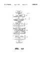
- FIG. 10is a flow chart showing processing of a CPU shown in FIG. 7 according to the present invention.
- FIG. 11is a perspective view of a gap adjusting apparatus according to the present invention.
- FIG. 12is a block diagram showing a circuit construction of a second embodiment according to the present invention.
- FIG. 13is a flowchart showing processing of a CPU shown in FIG. 12 according to the present invention.
- FIGS. 1 and 2Front and rear perspective views showing a mechanism structure of a print engine of an ink jet printer are illustrated in FIGS. 1 and 2, respectively.
- the print engineincludes a line feed mechanism 102, a carriage mechanism 104, a home assembly 106, a friction roller assembly 108, a carriage motor 116, a line feed motor 118, etc, and theses are assembled and installed in a frame 100.
- a reference symbol Sdesignates a sheet.
- the line feed mechanism 102includes, as shown in an exploded perspective view of FIG. 3, a frame base assembly 126 and a feed roller 114.
- the line feed mechanism 102conveys the sheet fed as indicated in FIG. 2 from a pickup unit (not shown) toward a recording head (not shown) mounted in a carriage 112 of the carriage mechanism 104.
- the recording headis provided by an ink cartridge (not shown) unified with an ink container.
- the ink cartridgeis exchangeable, and the recording head is installed opposite to the surface of the sheet at the bottom of the ink cartridge. If the sheet is inserted into a contact surface between the feed roller 114 and a friction roller 128, the sheet is conveyed toward the recording head by the feed roller 114 rotated by the line feed motor 118 to record an image and ejected to the exterior.
- a sheet sensor 120consisting of a transmission optical sensor 122 and an actuator feed 124.
- the actuator feed 124is installed just in front of the feed roller 114 and the friction roller 128, and cuts off an optical path between a luminous element and a light receiving element of the optical sensor 122. Under Such a state, if the sheet is fed, the actuator feed 124 is pushed by a front end of the sheet. Therefore, a light of the luminous element of the optical sensor 122 is transmitted to the light receiving element thereof, and the sheet sensor 120 senses that the sheet reaches a position between the feed roller 114 and the friction roller 128.
- the carriage mechanism 104shifts the ink cartridge mounted in the carriage 112 in the horizontal direction by the carriage motor 116.
- the carriage 112moves in the right and left horizontal direction along a transversely extended carrier shaft 110.
- the home assembly 106caps the recording head when the carriage 112 moves to a home position while the printer is not used.
- the cappingrepresents that the recording head is covered with a cap in order to prevent ink within a nozzle of the recording head from drying or being polluted. In this case, the nozzle is typically cleaned up.
- the friction roller assembly 108consists of a plurality of sub assemblies each having the friction roller 128, a friction roller guide 130 and a tension spring 132, and presses the sheet to the feed roller 114.
- the friction roller 128is installed at an axis parallel to the fees roller 114 and is in contact with the feed roller 114.
- One end of the friction roller guide 130is connected to the friction roller 128, and the other end thereof is connected to the spring 132 fixed to the frame 100.
- the friction roller guide 130elastically presses the friction roller 128 to the feed roller 114.
- FIG. 4A structure related to the conveyance of the sheet of the feed roller 114 and the friction roller assembly 108 is shown in FIG. 4.
- An opposite side of the friction roller guide 130 connected to the friction roller 128 which is in contact with the feed roller 114is pulled by the spring 132 in the direction of the frame 100, and thus the friction roller 128 presses the feed roller 114.
- the friction roller 128presses the feed roller 114.
- the friction roller 128is lifted by the thickness of the sheet by the insertion of the sheet but continues to elastically press the sheet to the feed roller 114. Therefore, the sheet is conveyed toward the recording head.
- the present inventionautomatically senses the thickness of the fed sheet in consideration of the above principles. Furthermore, the recording head is adjusted correspondingly to the sensed thickness of the sheet. Therefore, the optimal recording picture quality can be adoptively maintained according to the thickness of the sheet.
- FIG. 5shows a mechanism structure of a sheet thickness sensing apparatus for sensing the thickness of the sheet according to the present invention.
- a friction roller guide 136 having a reflective surface 138is used, and a reflective optical sensor 140 is separately installed opposite to the reflective surface 138. That is, the optical sensor 140 is fixed to the frame 100 so that the luminous element and the light receiving element of the optical sensor 140 may be opposite to the reflective surface 138.
- the reflective surface 138 and the optical sensor 140are installed at a portion to which the spring 132 is not connected from the roller guide 136. In FIG. 5, the spring 132 is not shown to avoid confusion because the spring 132 is overlapped with the optical sensor 140 if it is shown.
- the reflective surface 138 and the optical sensor 140are installed at one of the plurality of sub assemblies of the friction roller assembly 108, preferably at the sub assembly beside the home position. This is because the size of the sheet is not uniform. Since the home position is a reference position, even if the size of the sheet differs, the sheet passes through the home position and therefore the thickness of the sheet can be sensed.
- a reflective optical quantity of the optical sensor 140 with respect to the reflective surface 138is determined by a gap between the reflective surface 138 and the optical sensor 140.
- the reflective surface 138moves in a direction opposite to the moving direction of the friction roller 128 shifted by the thickness of the sheet by an operation of the friction roller guide 136.
- the moving amountcorresponds to the thickness of the sheet, a gap between the reflective surface 138 and the optical sensor 140 varies with the thickness of the sheet.
- the reflective optical quantity of the optical sensor 140varies in proportion to the thickness of the sheet. Namely, the reflective optical quantity gradually decreases as the thickness of the sheet becomes thicker, and gradually increases as the thickness of the sheet becomes thinner. If there is no sheet, the reflective optical quantity reaches the maximum. Examples of an operation state of the sheet thickness sensing apparatus of FIG. 5 according to a variation in the thickness of the sheet are shown in FIGS. 6A and 6B.
- FIGS. 6A and 6Billustrate relative operation states when the thickness of the sheet differs, FIG. 6A being the case the thickness of the sheet is thin and FIG. 6B being the case the thickness of the sheet is thick.
- the optical sensor 140generates a sensing signal of a voltage level corresponding to the reflective optical quantity supplied to the light receiving element.
- a sensing signalof a voltage level corresponding to the reflective optical quantity supplied to the light receiving element.
- the reflective optical quantity and the voltage level of the sensing signalare linear. Therefore, the thickness of the sheet can be sensed by the sensing signal generated from the optical sensor 140.
- the thickness of the sheetis sensed by the reflective optical sensor 140 using the conventional friction roller assembly 108, it is possible to sense the thickness of the sheet by adding the thickness sensing apparatus according to the present invention to a sheet convey path if the friction roller assembly 108 is not used.
- FIG. 7is a block diagram showing a circuit construction for adjusting the recording head by automatically sensing the thickness of the sheet.
- a thickness sensing circuit 162 constructed as shown in FIG. 8is added to the typical ink jet printer, and a recording head adjusting function performed by a CPU (central processing unit) 144 of a controller 142 as indicated in FIG. 10 is programmed in a ROM 148. Therefore, basic functions of other parts are the same as the typical ink jet printer.
- the controller 142has the CPU 144, an interface 146, the ROM (read only memory) 148 and a RAM (random access memory) 150.
- the CPU 144executes a program stored in the ROM 148 and controls each part of the printer through the interface 146.
- An execution program of the CPU 144 and various reference dataare stored in the ROM 148.
- Data generated during an operation of the CPU 144is temporarily stored in the RAM 150.
- the interface 146interfaces input/output signals between the CPU 144 and input/output devices, that is, signals between the CPU 144, and an operation panel 152, motor drivers 154 and 156, a head driver 158, a thickness sensing circuit 162 and a sheet sensor 120.
- the operation panel 152has a plurality of buttons for receiving various commands and a display unit for displaying various operation states by the control of the CPU 144.
- the motor driver 154drives the carriage motor 116 by the control of the CPU 144.
- the carriage motor 116is driven by the motor driver 154 and shifts the carriage 112 in the horizontal direction.
- the motor driver 156drives the line feed motor 118 by the control of the CPU 144.
- the line feed motor 118is driven by the motor driver 156 and feeds and conveys the sheet.
- the head driver 158drives a recording head 160 mounted in the carriage 112 by the control of the CPU 144 and records an image on the sheet.
- the recording head 160has a plurality of nozzles and is driven by the head driver 158.
- the recording head 160records the image on the sheet by jetting ink through the nozzles.
- the thickness sensing circuit 162includes, as described previously, the optical sensor 140 and supplies a sheet thickness value corresponding to the reflective optical quantity to the CPU 144.
- the sheet sensor 120installed as indicated in FIG. 2 senses the sheet and informs the CPU 144 that the sheet is fed.
- FIG. 8is a detailed circuit diagram of the thickness sensing circuit 162 shown in FIG. 7.
- the luminous element of the optical sensor 140that is, a light emitting diode LED is forwardly connected between a power source voltage Vcc through a resistor RI and a ground.
- the light receiving element of the optical sensor 140that is, a phototransistor PT is connected between the power source voltage Vcc through a resistor R2 and a noninverting input terminal (+) of an amplifier 164. Therefore, a sensing signal having the voltage level corresponding to the reflective optical quantity is generated by the phototransistor PT.
- the sensing signalis amplified by the amplifier 164 and supplied to an analog-to-digital converter (ADC) 166.
- the ADC 166converts the sensing signal into digital data having a value corresponding to its voltage level and supplies the digital data to the CPU 144 through the interface 146 as a thickness sensing value V T .
- An output state of the thickness sensing circuit 162 as a function of a variation in the thickness of the sheetis indicated in FIG. 9.
- T Iis a thickness range of a relatively thin sheet
- T2is a thickness range of a medium sheet
- T3is a thickness range of a thick sheet.
- the CPU 144confirms the thickness sensing value V T generated from the thickness sensing circuit 162, and judges that the Currently fed sheet is a thin sheet if the thickness sensing value V T within the range Of V T1 , that it is a medium sheet if V T within the range V 1 , and that it is a thick sheet if V T is within the range V T3 .
- FIG. 10is a processing flow of the CPU 144 shown in FIG. 7 according to the present invention. There is shown a process for sensing the thickness of the sheet by the thickness sensing circuit 162 when the sheet reaches the thickness sensing apparatus of FIG. 5 after feeding the sheet and for adjusting a head driving enable time of the recording head correspondingly to the sensed thickness of the sheet.
- the CPU 144starts to feed the sheet from the pickup unit (not shown) by driving the line feed motor 118 in response to a print start command at step Al.
- the CPU 144checks whether the sheet is sensed by the sheet sensor 120 at step A2. Generally, when feeding the sheet, the CPU 144 backwardly rotates the line feed motor 118 to rotate a pickup roller (not shown). When the sheet reaches the sheet sensor 120, the CPU 144 forwardly rotates the line feed motor 118 to rotate the feed roller 114. If the line feed motor 118 is backwardly rotated, power is transmitted only to the pickup roller and not transmitted to the feed roller 114. If the line feed motor 118 is forwardly rotated, the power is transmitted not to the pickup roller but to the feed roller 114. Therefore, if the sheet reaches the feed roller 114, a front end of the sheet temporarily stops until the feed roller 114 starts to rotate under the state that it is inserted between the feed roller 114 and the friction roller 128. Hence, the sheet is aligned.
- the CPU 144If the sheet is sensed by the sheet sensor 120, the front end of the sheet stops under the state it is inserted between the feed roller 114 and the friction roller 128. Then the CPU 144 reads the sheet thickness value V T generated from the thickness sensing circuit 162 at step A3. As mentioned above, the sheet thickness value V T corresponds to the thickness of the sheet. The CPU 144 retrieves the head driving enable time corresponding to the sheet thickness value V T from a lookup table previously stored in the ROM 148 at step A4. The lookup table is listed below in Table 1.
- the CPU 144alters the head driving enable time of the recording head 160 to the retrieved head driving enable time at step A5. That is, the CPU 144 adjusts the head driving enable time correspondingly to the range of the sheet thickness value V T among a plurality of differently set adjusting ranges. If the thickness of the sheet is thin, the CPU 144 lengthens the head driving enable time, and if the thickness of the sheet is thick, it shortens the head driving enable time. However, if the fed sheet is the same as the previous sheet, there is no need to adjust the head driving enable time. Generally, since the head driving enable time is adjusted by the CPU 144 by controlling the head driver 158, the detailed description therefor is omitted.
- the size of an ink drop jetted from the recording head 160becomes larger by lengthening the head driving enable time. If the thickness of the sheet is thick, the size of the ink drop becomes smaller by shortening the head driving enable time. After the recording head is adjusted, a printing operation is started.
- FIG. 11a gap adjusting apparatus is shown in FIG. 11, and a circuit construction according thereto is illustrated in FIG. 12.
- a motor driver 182 and a gap adjusting motor 172are added to the circuit construction of FIG. 7.
- FIG. 11is a perspective view of the gap adjusting apparatus according to the present invention.
- a carrier shaft 168provides a horizontal moving axis for an ink cartridge 170, that is, for the carriage 112.
- the carrier shaft 168has a cam structure and both horizontal end portions thereof are rotated at the frame 100, unlike the typical carrier shaft I 10.
- This carrier shaft 168is rotated by the gap adjusting motor 172.
- a gear 174 installed at a rotary axis of the gap adjusting motor 172is connected to a gear 176 installed at one horizontal end portion of the carrier shaft 168.
- a locked projection 180 projecting from the frame 100is for setting an initial position of a cam part of the carrier shaft 168 and causes a rib 178 protruding from the gear 176 to be correspondingly locked to the locked projection 180.
- the carrier shaft 168 shown in FIG. 11illustrates an its initial state.
- the CPU 144 shown in FIG. 12initializes the position of the recording head before adjusting the head gap by the gap adjusting motor 172.
- the CPU 144rotates the gap adjusting motor 172 clockwise through the motor driver 182 by a constant distance.
- the motor driver 182drives the gap adjusting motor 172 by the control of the driving direction and of the number of pulses of the CPU 144.
- the gear 176is rotated counterclockwise. If the rib 178 of the gear 176 is locked to the locked projection 180, the gear 176 stops rotating, and the carrier shaft 168 becomes an initial state.
- the height of the horizontal moving axis of the carrier shaft 168is the lowest state. Therefore, the height of the carriage 112 is also the lowest state, and the height of the recording head 160 fixed to the bottom of the ink cartridge 170 becomes the lowest state.
- An initially distance for rotating the gap adjusting motor 172is appropriately set in consideration of the previous height of the recording head 160, that is, the previous position of the rib 178.
- the gap adjusting motor 172If the gap adjusting motor 172 is rotated counterclockwise, the gear 176 and the carrier shaft 168 are rotated clockwise, and the height of the ink cartridge 170 or the height of the recording head 160 becomes high. Under the state that the height of the recording head 160 is higher than the initial state, if the gap adjusting motor 172 is rotated clockwise, the gear 176 and the carrier shaft 168 are rotated counterclockwise, and the height of the recording head 160 becomes again low. That is, the head gap can be automatically adjusted by adjusting the height of the recording head 160 using the gap adjusting apparatus according to the thickness of the sheet.
- FIG. 13is a processing flow of the CPU 144 shown in FIG. 12. There is shown a process for sensing the thickness of the sheet by the thickness sensing circuit 162 when the sheet reaches the thickness sensing apparatus of FIG. 5 after the sheet is fed and for adjusting the head gap by the gap adjusting apparatus of FIG. 11 correspondingly to the sensed thickness of the sheet.
- the CPU 144starts to feed the sheet from the pickup unit by driving the line feed motor 118 in response to a print start signal at step B1.
- the CPU 144checks whether the sheet is sensed at step B2. If the sheet is sensed, the CPU 144 reads the sheet thickness value V T generated from the thickness sensing circuit 162 at step B3.
- the CPU 144retrieves the number of steps of the gap adjusting motor 172 on the basis of the sheet thickness value V T from a lookup table previously stored in the ROM 148 at step B4.
- the lookup tableis listed below in Table 2.
- the CPU 144drives the gap adjusting motor 172 by controlling the motor driver 182 at step B5, thereby adjusting the head gap.
- the CPU 144adjusts the height of the recording head to the initial state and rotates the gap adjusting motor 172 counterclockwise by the retrieved number of pulses. Namely, the CPU 144 adjusts the head gap correspondingly to the range of the thickness of the sheet V T among a plurality of differently set adjusting ranges. If the thickness of the sheet is thin, the CPU 144 makes the height the recording head 160 lower by driving the gap adjusting motor 172 by the smaller number of pulses.
- the CPU 144makes the height of the recording head 160 higher by driving the gap adjusting motor 172 by the larger number of pulses. However, if the fed sheet is the same as the previous sheet, there is no need to adjust the height of the recording head 160.
- the height of the recording head 160is lowered. If the thickness of the sheet is thick, the height of the recording head 160 is raised, thereby constantly maintaining the head gap. Under the state that the recording head is adjusted, a printing operation is started.
- the head gapis adoptively adjusted even though the thickness of the sheet varies, the head gap is maintained at a constant state, and thus the optimal recording picture quality can be obtained.
- the present inventionnot only senses the thickness of the sheet accurately but also lowers the cost of a product by using the optical sensor instead of the pressure sensor. Moreover, the user need not manipulate the adjusting lever since the recording head is automatically adjusted according to the thickness of the sheet, and the optimal recording picture quality can be maintained.
- the sheet thickness sensing apparatus embodying the present inventionis applied to an ink jet printer, it may be applied to all image recording apparatuses requiring a sheet thickness sensing function. Furthermore, a recording head adjusting technique may be applied not only to the ink jet printer but also to all recording apparatuses using ink jet recording, for example, to a facsimile machine of the ink jet recording. When sensing the thickness of the sheet, other sheet thickness sensing apparatuses as disclosed in the above Korea Patent Application No. 94-12167 may be used instead of the inventive sheet thickness sensing apparatus.
Landscapes
- Physics & Mathematics (AREA)
- General Physics & Mathematics (AREA)
- Ink Jet (AREA)
- Common Mechanisms (AREA)
- Controlling Sheets Or Webs (AREA)
- Length Measuring Devices By Optical Means (AREA)
Abstract
Description
TABLE 1 ______________________________________ Thickness of sheet Sheet thickness value V.sub.T Head driving enable time ______________________________________ thin V.sub.T1 3.0 μs medium V.sub.T2 2.5 μs thick V.sub.T3 2.0 μs ______________________________________
TABLE 2 ______________________________________ Thickness of sheet Sheet thickness value V.sub.T Number of pulses ______________________________________ thin V.sub.T1 20 medium V.sub.T2 25 thick V.sub.T3 30 ______________________________________
Claims (28)
Applications Claiming Priority (2)
| Application Number | Priority Date | Filing Date | Title |
|---|---|---|---|
| KR199624077 | 1996-06-26 | ||
| KR1019960024077AKR100186611B1 (en) | 1996-06-26 | 1996-06-26 | Paper thickness sensing device of image recording apparatus and recording head auto-controlling apparatus of inkjet recording apparatus and method thereof |
Publications (1)
| Publication Number | Publication Date |
|---|---|
| US5806992Atrue US5806992A (en) | 1998-09-15 |
Family
ID=19463602
Family Applications (1)
| Application Number | Title | Priority Date | Filing Date |
|---|---|---|---|
| US08/882,936Expired - LifetimeUS5806992A (en) | 1996-06-26 | 1997-06-26 | Sheet thickness sensing technique and recording head automatic adjusting technique of ink jet recording apparatus using same |
Country Status (5)
| Country | Link |
|---|---|
| US (1) | US5806992A (en) |
| EP (1) | EP0816800B1 (en) |
| JP (1) | JP3048339B2 (en) |
| KR (1) | KR100186611B1 (en) |
| DE (1) | DE69714922T2 (en) |
Cited By (44)
| Publication number | Priority date | Publication date | Assignee | Title |
|---|---|---|---|---|
| US6120196A (en)* | 1996-02-23 | 2000-09-19 | Copyer Co., Ltd. | Image forming device using multiple factors to adjust print position |
| US6360657B1 (en)* | 1998-08-31 | 2002-03-26 | Seiko Precision, Inc. | Printer |
| US6382752B1 (en)* | 2000-01-07 | 2002-05-07 | Hewlett-Packard Company | Adjustable chassis for automated writing instrument carriage |
| US20020110396A1 (en)* | 1999-11-18 | 2002-08-15 | Fujitsu Limited | Thickness detecting apparatus |
| US6467977B2 (en) | 2000-12-19 | 2002-10-22 | Hewlett-Packard Company | Media weight sensor using a resonant piezoelectric element |
| US6485205B2 (en) | 2000-12-19 | 2002-11-26 | Hewlett-Packard Company | Media weight sensor using an acoustic resonator |
| US6488422B1 (en)* | 2000-05-23 | 2002-12-03 | Silverbrook Research Pty Ltd | Paper thickness sensor in a printer |
| US20030016959A1 (en)* | 2001-07-17 | 2003-01-23 | Oki Data Corporation | Image-forming apparatus |
| US6547384B2 (en)* | 2000-02-15 | 2003-04-15 | Master Mind Co., Ltd. | Printing apparatus and method |
| US20030116724A1 (en)* | 2001-12-24 | 2003-06-26 | Lg N-Sys Inc. | Paper thickness detecting device |
| US6615714B2 (en)* | 1999-12-07 | 2003-09-09 | Fuji Photo Film Co., Ltd. | Goods-wrapping apparatus including a printer |
| US6616355B2 (en)* | 2000-10-30 | 2003-09-09 | Vutek, Inc. | Printing system for accommodating various substrate thicknesses |
| US20040049712A1 (en)* | 2002-09-11 | 2004-03-11 | Betker Michael Richard | Processor system with cache-based software breakpoints |
| US20040061873A1 (en)* | 2002-09-26 | 2004-04-01 | Davis Brett L. | Method and apparatus for detecting media thickness |
| US6726357B2 (en) | 2002-05-20 | 2004-04-27 | Hewlett-Packard Development Company, L.P. | Media identification system |
| US20040080587A1 (en)* | 2000-05-23 | 2004-04-29 | Silverbrook Research Pty Ltd | Ink distribution assembly |
| US6734417B2 (en)* | 2002-05-08 | 2004-05-11 | Hewlett-Packard Development Company, L.P. | Displacement measurement system and sheet feed system incorporating the same |
| US6733102B2 (en)* | 2000-10-17 | 2004-05-11 | Seiko Epson Corporation | Ink jet recording apparatus |
| US20040090478A1 (en)* | 2002-11-07 | 2004-05-13 | Pitney Bowes Incorporated | Contour correcting printer |
| US20040100512A1 (en)* | 2000-08-30 | 2004-05-27 | L&P Property Management Company | Method and apparatus for printing on rigid panels and other contoured, textured or thick substrates |
| US20040113998A1 (en)* | 2000-05-23 | 2004-06-17 | Silverbrook Research Pty Ltd | Printhead chassis assembly |
| US20040145107A1 (en)* | 2003-01-28 | 2004-07-29 | Luque Phillip R. | Scale |
| US20040212644A1 (en)* | 2003-04-23 | 2004-10-28 | Chung-Seon Kwag | Printer capable of automatically adjusting inkjet clearance for printing on thick, non flexible printing material |
| US20050002713A1 (en)* | 2000-05-23 | 2005-01-06 | Kia Silverbrook | Printer for accomodating varying page thickness |
| US20050056575A1 (en)* | 2003-08-01 | 2005-03-17 | Lg N-Sys Inc. | Media thickness detector |
| US20060007276A1 (en)* | 2000-05-23 | 2006-01-12 | Silverbrook Research Pty Ltd | Ink distribution structure for a printhead |
| US6998628B2 (en) | 2002-11-21 | 2006-02-14 | Lexmark International, Inc. | Method of media type differentiation in an imaging apparatus |
| US20060203067A1 (en)* | 2005-03-11 | 2006-09-14 | Toshiba Tec Kabushiki Kaisha | Recording medium processing apparatus |
| US20070009275A1 (en)* | 2005-06-24 | 2007-01-11 | Olympus Corporation | Image forming apparatus |
| US7210867B1 (en) | 2000-05-24 | 2007-05-01 | Silverbrook Research Pty Ltd | Paper thickness sensor in a printer |
| US20070103531A1 (en)* | 2005-11-08 | 2007-05-10 | Xerox Corporation | Transfix roller load controlled by force feedback |
| US7286257B1 (en)* | 1999-03-01 | 2007-10-23 | Gemplus | Graphic printing machine for card-type storage medium, method for printing said storage media and storage media |
| US20070291056A1 (en)* | 2006-06-16 | 2007-12-20 | Brother Kogyo Kabushiki Kaisha | Inkjet Recording Apparatus |
| US20080265486A1 (en)* | 2007-04-27 | 2008-10-30 | Hewlett-Packard Development Company Lp | Mechanically triggered nip drive shaft |
| US20090174746A1 (en)* | 2007-12-27 | 2009-07-09 | Hsien-Chang Lin | Spacing-sensing apparatus for use in a printing module of printer |
| US20090257100A1 (en)* | 2008-04-13 | 2009-10-15 | Troy Roberts | Method And Apparatus For Ascertaining And Adjusting Friction Between Media Pages In A Document Feeder |
| US20110109689A1 (en)* | 2009-11-06 | 2011-05-12 | Canon Kabushiki Kaisha | Recording apparatus |
| US8702205B2 (en) | 2000-05-23 | 2014-04-22 | Zamtec Ltd | Printhead assembly incorporating ink distribution assembly |
| US9278531B1 (en)* | 2014-11-12 | 2016-03-08 | Xerox Corporation | Print head protection device for inkjet printers |
| US9527320B2 (en)* | 2015-04-23 | 2016-12-27 | Xerox Corporation | Inkjet print head protection by acoustic sensing of media |
| US9802427B1 (en) | 2017-01-18 | 2017-10-31 | Datamax-O'neil Corporation | Printers and methods for detecting print media thickness therein |
| US9835997B2 (en)* | 2014-07-25 | 2017-12-05 | Konica Minolta, Inc. | Image forming apparatus having conveyance roller section with nip angle adjusting section |
| US20180022125A1 (en)* | 2015-04-10 | 2018-01-25 | Océ-Technologies B.V. | Printer with height adjustable print head |
| CN114981092A (en)* | 2020-01-21 | 2022-08-30 | 株式会社理光 | Paper feeding device and image forming apparatus including the same |
Families Citing this family (7)
| Publication number | Priority date | Publication date | Assignee | Title |
|---|---|---|---|---|
| US6189879B1 (en)* | 1998-11-09 | 2001-02-20 | Heidelberger Druckmaschinen Ag | Thickness measurement apparatus |
| DE10013743B4 (en)* | 2000-03-20 | 2009-03-19 | Giesecke & Devrient Gmbh | Device for contacting thickness measurement of sheet material |
| JP4654696B2 (en)* | 2005-01-21 | 2011-03-23 | 富士ゼロックス株式会社 | Paper judging method and paper measuring device |
| TWI353885B (en)* | 2009-06-26 | 2011-12-11 | Primax Electronics Ltd | Thickness detecting mechanism |
| JP4914475B2 (en)* | 2009-10-01 | 2012-04-11 | キヤノン株式会社 | Inkjet recording device |
| CN102114990B (en)* | 2009-12-30 | 2012-12-26 | 致伸科技股份有限公司 | Automatic paper feeder |
| EP2570450A1 (en) | 2011-09-14 | 2013-03-20 | Sika Technology AG | Shape memory material based on a structural adhesive |
Citations (21)
| Publication number | Priority date | Publication date | Assignee | Title |
|---|---|---|---|---|
| US4580914A (en)* | 1984-08-02 | 1986-04-08 | Metromedia, Inc. | Apparatus and method for positioning an ink-jet printing head |
| US4847638A (en)* | 1985-11-15 | 1989-07-11 | Canon Kabushiki Kaisha | Recorder |
| US4917512A (en)* | 1988-01-28 | 1990-04-17 | Seiko Epson Corporation | Apparatus for automatically adjusting a gap between a platen and a print head |
| US4927277A (en)* | 1988-04-06 | 1990-05-22 | Brother Kogyo Kabushiki Kaisha | Printer having a device for adjusting the printing condition, depending upon paper thickness |
| US5051008A (en)* | 1989-03-04 | 1991-09-24 | International Business Machines Corp. | Automatic gap adjusting mechanism |
| US5065169A (en)* | 1988-03-21 | 1991-11-12 | Hewlett-Packard Company | Device to assure paper flatness and pen-to-paper spacing during printing |
| US5088848A (en)* | 1990-03-20 | 1992-02-18 | Ing. Olivetti & C., S.P.A. | Printing sheet feed and aligning system for a printer |
| US5156464A (en)* | 1991-05-31 | 1992-10-20 | Brother Kogyo Kabushiki Kaisha | Printer having gap adjusting apparatus for print head |
| US5193918A (en)* | 1988-09-08 | 1993-03-16 | Mannesmann Aktiengesellschaft | Print-head positioning system having a paper sensor |
| US5204537A (en)* | 1990-03-30 | 1993-04-20 | Recognition Equipment Incorporated | Thickness sensor comprising a leaf spring means, and a light sensor |
| US5227809A (en)* | 1991-06-17 | 1993-07-13 | Tektronix, Inc. | Automatic print head spacing mechanism for ink jet printer |
| US5257867A (en)* | 1991-10-04 | 1993-11-02 | Brother Kogyo Kabushiki Kaisha | Printer with print gap control |
| JPH05345411A (en)* | 1992-06-15 | 1993-12-27 | Canon Inc | Ink jet recording apparatus |
| US5291227A (en)* | 1991-05-17 | 1994-03-01 | Ricoh Company, Ltd. | Ink jet printer having improved paper transport mechanism |
| US5316395A (en)* | 1990-04-25 | 1994-05-31 | Fujitsu Limited | Printing apparatus having head GAP adjusting device. |
| US5360276A (en)* | 1990-08-10 | 1994-11-01 | Siemens Nixdorf Informationssysteme Aktiengesellschaft | Printing device with adjustable printing head gap |
| US5366301A (en)* | 1993-12-14 | 1994-11-22 | Hewlett-Packard Company | Record media gap adjustment system for use in printers |
| US5468076A (en)* | 1993-06-25 | 1995-11-21 | Kabushiki Kaisha Tec | Print gap adjusting device |
| US5486063A (en)* | 1995-01-09 | 1996-01-23 | Intermec Incorporated | Method and apparatus for sensing the length of label or tag media by detecting changes in relative thickness |
| US5576744A (en)* | 1992-07-06 | 1996-11-19 | Canon Kabushiki Kaisha | Recording apparatus and method compensating for varying gap between recording head and recording medium |
| US5618120A (en)* | 1991-07-29 | 1997-04-08 | Canon Kabushiki Kaisha | Recording apparatus having means for detecting the positions of a recording medium |
Family Cites Families (2)
| Publication number | Priority date | Publication date | Assignee | Title |
|---|---|---|---|---|
| US4737645A (en)* | 1985-11-01 | 1988-04-12 | Creative Associates Limited Partnership | Printer supplies monitoring system |
| JP3500225B2 (en)* | 1995-04-25 | 2004-02-23 | シチズン時計株式会社 | Impact dot printer |
- 1996
- 1996-06-26KRKR1019960024077Apatent/KR100186611B1/ennot_activeExpired - Fee Related
- 1997
- 1997-06-26DEDE69714922Tpatent/DE69714922T2/ennot_activeExpired - Lifetime
- 1997-06-26JPJP9170737Apatent/JP3048339B2/ennot_activeExpired - Lifetime
- 1997-06-26EPEP97304540Apatent/EP0816800B1/ennot_activeExpired - Lifetime
- 1997-06-26USUS08/882,936patent/US5806992A/ennot_activeExpired - Lifetime
Patent Citations (21)
| Publication number | Priority date | Publication date | Assignee | Title |
|---|---|---|---|---|
| US4580914A (en)* | 1984-08-02 | 1986-04-08 | Metromedia, Inc. | Apparatus and method for positioning an ink-jet printing head |
| US4847638A (en)* | 1985-11-15 | 1989-07-11 | Canon Kabushiki Kaisha | Recorder |
| US4917512A (en)* | 1988-01-28 | 1990-04-17 | Seiko Epson Corporation | Apparatus for automatically adjusting a gap between a platen and a print head |
| US5065169A (en)* | 1988-03-21 | 1991-11-12 | Hewlett-Packard Company | Device to assure paper flatness and pen-to-paper spacing during printing |
| US4927277A (en)* | 1988-04-06 | 1990-05-22 | Brother Kogyo Kabushiki Kaisha | Printer having a device for adjusting the printing condition, depending upon paper thickness |
| US5193918A (en)* | 1988-09-08 | 1993-03-16 | Mannesmann Aktiengesellschaft | Print-head positioning system having a paper sensor |
| US5051008A (en)* | 1989-03-04 | 1991-09-24 | International Business Machines Corp. | Automatic gap adjusting mechanism |
| US5088848A (en)* | 1990-03-20 | 1992-02-18 | Ing. Olivetti & C., S.P.A. | Printing sheet feed and aligning system for a printer |
| US5204537A (en)* | 1990-03-30 | 1993-04-20 | Recognition Equipment Incorporated | Thickness sensor comprising a leaf spring means, and a light sensor |
| US5316395A (en)* | 1990-04-25 | 1994-05-31 | Fujitsu Limited | Printing apparatus having head GAP adjusting device. |
| US5360276A (en)* | 1990-08-10 | 1994-11-01 | Siemens Nixdorf Informationssysteme Aktiengesellschaft | Printing device with adjustable printing head gap |
| US5291227A (en)* | 1991-05-17 | 1994-03-01 | Ricoh Company, Ltd. | Ink jet printer having improved paper transport mechanism |
| US5156464A (en)* | 1991-05-31 | 1992-10-20 | Brother Kogyo Kabushiki Kaisha | Printer having gap adjusting apparatus for print head |
| US5227809A (en)* | 1991-06-17 | 1993-07-13 | Tektronix, Inc. | Automatic print head spacing mechanism for ink jet printer |
| US5618120A (en)* | 1991-07-29 | 1997-04-08 | Canon Kabushiki Kaisha | Recording apparatus having means for detecting the positions of a recording medium |
| US5257867A (en)* | 1991-10-04 | 1993-11-02 | Brother Kogyo Kabushiki Kaisha | Printer with print gap control |
| JPH05345411A (en)* | 1992-06-15 | 1993-12-27 | Canon Inc | Ink jet recording apparatus |
| US5576744A (en)* | 1992-07-06 | 1996-11-19 | Canon Kabushiki Kaisha | Recording apparatus and method compensating for varying gap between recording head and recording medium |
| US5468076A (en)* | 1993-06-25 | 1995-11-21 | Kabushiki Kaisha Tec | Print gap adjusting device |
| US5366301A (en)* | 1993-12-14 | 1994-11-22 | Hewlett-Packard Company | Record media gap adjustment system for use in printers |
| US5486063A (en)* | 1995-01-09 | 1996-01-23 | Intermec Incorporated | Method and apparatus for sensing the length of label or tag media by detecting changes in relative thickness |
Cited By (132)
| Publication number | Priority date | Publication date | Assignee | Title |
|---|---|---|---|---|
| US6120196A (en)* | 1996-02-23 | 2000-09-19 | Copyer Co., Ltd. | Image forming device using multiple factors to adjust print position |
| US6360657B1 (en)* | 1998-08-31 | 2002-03-26 | Seiko Precision, Inc. | Printer |
| US7286257B1 (en)* | 1999-03-01 | 2007-10-23 | Gemplus | Graphic printing machine for card-type storage medium, method for printing said storage media and storage media |
| US20020110396A1 (en)* | 1999-11-18 | 2002-08-15 | Fujitsu Limited | Thickness detecting apparatus |
| US20070241743A1 (en)* | 1999-11-18 | 2007-10-18 | Fujitsu Limited | Apparatus which detects the thickness of a sheet of paper such as a bank note |
| US7323867B2 (en) | 1999-11-18 | 2008-01-29 | Fujitsu Limited | Apparatus which detects the thickness of a sheet of paper such as a bank note |
| US20050158102A1 (en)* | 1999-12-07 | 2005-07-21 | Fuji Photo Film Co., Ltd. | Goods-wrapping apparatus including a printer |
| US7086793B2 (en) | 1999-12-07 | 2006-08-08 | Fuji Photo Film Co., Ltd. | Goods-wrapping apparatus including a printer |
| US20040094049A1 (en)* | 1999-12-07 | 2004-05-20 | Fuji Photo Film Co., Ltd. | Goods-wrapping apparatus including a printer |
| US7028614B2 (en) | 1999-12-07 | 2006-04-18 | Fuji Photo Film Co., Ltd. | Goods-wrapping apparatus including a printer |
| US6615714B2 (en)* | 1999-12-07 | 2003-09-09 | Fuji Photo Film Co., Ltd. | Goods-wrapping apparatus including a printer |
| US6920736B2 (en) | 1999-12-07 | 2005-07-26 | Fuji Photo Film Co., Ltd. | Goods-wrapping apparatus including a printer |
| US20040093830A1 (en)* | 1999-12-07 | 2004-05-20 | Fuji Photo Film Co., Ltd. | Goods-wrapping apparatus including a printer |
| US6626511B2 (en)* | 2000-01-07 | 2003-09-30 | Hewlett Packard Development Company, L.P. | Adjustable chassis for automated writing instrument carriage |
| US6382752B1 (en)* | 2000-01-07 | 2002-05-07 | Hewlett-Packard Company | Adjustable chassis for automated writing instrument carriage |
| US6547384B2 (en)* | 2000-02-15 | 2003-04-15 | Master Mind Co., Ltd. | Printing apparatus and method |
| US20050110844A1 (en)* | 2000-05-23 | 2005-05-26 | Kia Silverbrook | Multi-function printhead platen |
| US20060007276A1 (en)* | 2000-05-23 | 2006-01-12 | Silverbrook Research Pty Ltd | Ink distribution structure for a printhead |
| US7748833B2 (en) | 2000-05-23 | 2010-07-06 | Silverbrook Research Pty Ltd | Ink distribution structure with a laminated ink supply stack for an inkjet printer |
| US20100165045A1 (en)* | 2000-05-23 | 2010-07-01 | Silverbrook Research Pty Ltd | Print engine assembly with rotatable platen defining cavity for holding blotting material |
| US7740338B2 (en) | 2000-05-23 | 2010-06-22 | Silverbrook Research Pty Ltd | Printhead assembly having a pressurised air supply |
| US20040080587A1 (en)* | 2000-05-23 | 2004-04-29 | Silverbrook Research Pty Ltd | Ink distribution assembly |
| US7824021B2 (en) | 2000-05-23 | 2010-11-02 | Silverbrook Research Pty Ltd | Printhead assembly with printheads within a laminated stack which, in turn is within an ink distribution structure |
| US20100134559A1 (en)* | 2000-05-23 | 2010-06-03 | Silverbrook Research Pty Ltd | Printhead assembly incorporating laminated ink distribution stack |
| US20040113998A1 (en)* | 2000-05-23 | 2004-06-17 | Silverbrook Research Pty Ltd | Printhead chassis assembly |
| US7686416B2 (en) | 2000-05-23 | 2010-03-30 | Silverbrook Research Pty Ltd | Print engine assembly having a rotatable platen providing different functional operations |
| US6786658B2 (en) | 2000-05-23 | 2004-09-07 | Silverbrook Research Pty. Ltd. | Printer for accommodating varying page thicknesses |
| US7658467B2 (en) | 2000-05-23 | 2010-02-09 | Silverbrook Research Pty Ltd | Printhead assembly laminated ink distribution stack |
| US6796731B2 (en) | 2000-05-23 | 2004-09-28 | Silverbrook Research Pty Ltd | Laminated ink distribution assembly for a printer |
| US20090058973A1 (en)* | 2000-05-23 | 2009-03-05 | Silverbrook Research Pty Ltd | Printing apparatus and method |
| US20050002713A1 (en)* | 2000-05-23 | 2005-01-06 | Kia Silverbrook | Printer for accomodating varying page thickness |
| US20050007421A1 (en)* | 2000-05-23 | 2005-01-13 | Kia Silverbrook | Ink and air distribution within a printer assembly |
| US20090033712A1 (en)* | 2000-05-23 | 2009-02-05 | Silverbrook Research Pty Ltd | Rotatable platen |
| US20090033713A1 (en)* | 2000-05-23 | 2009-02-05 | Silverbrook Research Pty Ltd | Method of operating inkjet printer |
| US7841710B2 (en) | 2000-05-23 | 2010-11-30 | Silverbrook Research Pty Ltd | Printhead assembly with a pressurized air supply for an inkjet printer |
| US20080284829A1 (en)* | 2000-05-23 | 2008-11-20 | Silverbrook Research Pty Ltd | Printhead assembly having a pressurised air supply |
| US20050140757A1 (en)* | 2000-05-23 | 2005-06-30 | Kia Silverbrook | Printhead assembly with stacked ink distribution sheets |
| US20050146564A1 (en)* | 2000-05-23 | 2005-07-07 | Kia Silverbrook | Ink jet printhead assembly with a multi-purpose rotary platen assembly |
| US7425053B2 (en) | 2000-05-23 | 2008-09-16 | Silverbrook Research Pty Ltd | Printhead assembly with a laminated ink distribution assembly |
| US7980658B2 (en) | 2000-05-23 | 2011-07-19 | Silverbrook Research Pty Ltd | Rotatable platen |
| US8282185B2 (en) | 2000-05-23 | 2012-10-09 | Zamtec Limited | Print engine assembly with rotatable platen defining cavity for holding blotting material |
| US20050162468A1 (en)* | 2000-05-23 | 2005-07-28 | Kia Silverbrook | Printhead assembly |
| US6984080B2 (en) | 2000-05-23 | 2006-01-10 | Silverbrook Research Pty Ltd | Laminated distribution structure |
| US20040080588A1 (en)* | 2000-05-23 | 2004-04-29 | Silverbrook Research Pty Ltd | Laminated distribution structure |
| US20060008307A1 (en)* | 2000-05-23 | 2006-01-12 | Silverbrook Research Pty Ltd | Print engine assembly with an elongate converging ink distribution assembly |
| US20060013631A1 (en)* | 2000-05-23 | 2006-01-19 | Silverbrook Research Pty Ltd | Inkjet printing assembly with multi-purpose platen assembly |
| US6988840B2 (en) | 2000-05-23 | 2006-01-24 | Silverbrook Research Pty Ltd | Printhead chassis assembly |
| US6994419B2 (en) | 2000-05-23 | 2006-02-07 | Silverbrook Research Pty Ltd | Multi-function printhead platen |
| US20080158296A1 (en)* | 2000-05-23 | 2008-07-03 | Silverbrook Research Pty Ltd | Printhead assembly laminated ink distribution stack |
| US6997626B2 (en) | 2000-05-23 | 2006-02-14 | Silverbrook Research Pty Ltd | Ink and air distribution within a printer assembly |
| US6997625B2 (en) | 2000-05-23 | 2006-02-14 | Silverbrook Research Pty Ltd | Ink distribution assembly |
| US20080111849A1 (en)* | 2000-05-23 | 2008-05-15 | Silverbrook Research Pty Ltd | Print Engine Assembly Having A Rotatable Platen Providing Different Functional Operations |
| US7004652B2 (en) | 2000-05-23 | 2006-02-28 | Silverbrook Research Pty Ltd | Printer for accommodating varying page thickness |
| US7021742B2 (en) | 2000-05-23 | 2006-04-04 | Silverbrook Research Pty Ltd | Ink jet printhead assembly with a multi-purpose rotary platen assembly |
| US8696096B2 (en) | 2000-05-23 | 2014-04-15 | Zamtec Ltd | Laminated ink supply structure mounted in ink distribution arrangement of an inkjet printer |
| US20060120785A1 (en)* | 2000-05-23 | 2006-06-08 | Silverbrook Research Pty Ltd | Printer having adjustable media support |
| US7083258B2 (en) | 2000-05-23 | 2006-08-01 | Silverbrook Research Pty Ltd | Printhead assembly |
| US8702205B2 (en) | 2000-05-23 | 2014-04-22 | Zamtec Ltd | Printhead assembly incorporating ink distribution assembly |
| US20080106579A1 (en)* | 2000-05-23 | 2008-05-08 | Silverbrook Research Pty Ltd | Ink Distribution Structure With A Laminated Ink Supply Stack For An Inkjet Printer |
| US7364377B2 (en) | 2000-05-23 | 2008-04-29 | Silverbrook Research Pty Ltd | Print engine assembly with an elongate converging ink distribution assembly |
| US7114868B2 (en) | 2000-05-23 | 2006-10-03 | Silverbrook Research Pty Ltd | Inkjet printing assembly with multi-purpose platen assembly |
| US7357583B2 (en) | 2000-05-23 | 2008-04-15 | Silverbrook Research Pty Ltd | Print engine assembly with overlapping ink printing IC's |
| US20070013739A1 (en)* | 2000-05-23 | 2007-01-18 | Silverbrook Research Pty Ltd | Print engine assembly with slotted chassis |
| US7328994B2 (en)* | 2000-05-23 | 2008-02-12 | Silverbrook Research Pty Ltd | Print engine assembly with slotted chassis |
| US7210866B2 (en) | 2000-05-23 | 2007-05-01 | Silverbrook Research Pty Ltd | Printer having adjustable media support |
| US7213989B2 (en) | 2000-05-23 | 2007-05-08 | Silverbrook Research Pty Ltd | Ink distribution structure for a printhead |
| US7325986B2 (en) | 2000-05-23 | 2008-02-05 | Silverbrook Research Pty Ltd | Printhead assembly with stacked ink distribution sheets |
| US6488422B1 (en)* | 2000-05-23 | 2002-12-03 | Silverbrook Research Pty Ltd | Paper thickness sensor in a printer |
| US20070195115A1 (en)* | 2000-05-23 | 2007-08-23 | Silverbrook Research Pty Ltd | Printhead assembly with printheads within a laminated stack which, in turn is within an ink distribution structure |
| US9028048B2 (en) | 2000-05-23 | 2015-05-12 | Memjet Technology Ltd. | Printhead assembly incorporating ink distribution assembly |
| US9254655B2 (en) | 2000-05-23 | 2016-02-09 | Memjet Technology Ltd. | Inkjet printer having laminated stack for receiving ink from ink distribution molding |
| US20070189825A1 (en)* | 2000-05-24 | 2007-08-16 | Silverbrook Research Pty Ltd | Paper thickness compensation in a printer |
| US7954928B2 (en) | 2000-05-24 | 2011-06-07 | Silverbrook Research Pty Ltd | Printhead assembly having angled nested structure |
| US7517053B2 (en) | 2000-05-24 | 2009-04-14 | Silverbrook Research Pty Ltd | Printhead assembly with nested structure |
| US20110057989A1 (en)* | 2000-05-24 | 2011-03-10 | Silverbrook Research Pty Ltd | Inkjet printing device having rotating platen |
| US20110063364A1 (en)* | 2000-05-24 | 2011-03-17 | Silverbrook Research Pty Ltd | Rotating platen |
| US7210867B1 (en) | 2000-05-24 | 2007-05-01 | Silverbrook Research Pty Ltd | Paper thickness sensor in a printer |
| US20110063365A1 (en)* | 2000-05-24 | 2011-03-17 | Silverbrook Research Pty Ltd | Method of operating an inkjet printer |
| US7354208B2 (en) | 2000-05-24 | 2008-04-08 | Silverbrook Research Pty Ltd | Paper thickness compensation in a printer |
| US20110063363A1 (en)* | 2000-05-24 | 2011-03-17 | Silverbrook Research Pty Ltd | Inkjet printer having an inkjet printhead and a rotating platen |
| US20090195624A1 (en)* | 2000-05-24 | 2009-08-06 | Silverbrook Research Pty Ltd | Printhead Assembly Having Angled Nested Structure |
| US20040100512A1 (en)* | 2000-08-30 | 2004-05-27 | L&P Property Management Company | Method and apparatus for printing on rigid panels and other contoured, textured or thick substrates |
| US6733102B2 (en)* | 2000-10-17 | 2004-05-11 | Seiko Epson Corporation | Ink jet recording apparatus |
| US6616355B2 (en)* | 2000-10-30 | 2003-09-09 | Vutek, Inc. | Printing system for accommodating various substrate thicknesses |
| DE10151737B4 (en)* | 2000-12-19 | 2006-02-16 | Hewlett-Packard Development Co., L.P., Houston | Media weight sensor with a piezoelectric resonance element |
| US6485205B2 (en) | 2000-12-19 | 2002-11-26 | Hewlett-Packard Company | Media weight sensor using an acoustic resonator |
| US6467977B2 (en) | 2000-12-19 | 2002-10-22 | Hewlett-Packard Company | Media weight sensor using a resonant piezoelectric element |
| US20030016959A1 (en)* | 2001-07-17 | 2003-01-23 | Oki Data Corporation | Image-forming apparatus |
| US6850717B2 (en)* | 2001-07-17 | 2005-02-01 | Oki Data Corporation | Medium thickness detecting apparatus |
| US20030116724A1 (en)* | 2001-12-24 | 2003-06-26 | Lg N-Sys Inc. | Paper thickness detecting device |
| US6903358B2 (en)* | 2001-12-24 | 2005-06-07 | Lg N-Sys Inc. | Paper thickness detecting device |
| US6734417B2 (en)* | 2002-05-08 | 2004-05-11 | Hewlett-Packard Development Company, L.P. | Displacement measurement system and sheet feed system incorporating the same |
| US6726357B2 (en) | 2002-05-20 | 2004-04-27 | Hewlett-Packard Development Company, L.P. | Media identification system |
| US20040049712A1 (en)* | 2002-09-11 | 2004-03-11 | Betker Michael Richard | Processor system with cache-based software breakpoints |
| US20040061873A1 (en)* | 2002-09-26 | 2004-04-01 | Davis Brett L. | Method and apparatus for detecting media thickness |
| US6796628B2 (en) | 2002-11-07 | 2004-09-28 | Pitney Bowes Inc. | Contour correcting printer |
| US20040090478A1 (en)* | 2002-11-07 | 2004-05-13 | Pitney Bowes Incorporated | Contour correcting printer |
| US6998628B2 (en) | 2002-11-21 | 2006-02-14 | Lexmark International, Inc. | Method of media type differentiation in an imaging apparatus |
| US7091427B2 (en) | 2003-01-28 | 2006-08-15 | Hewlett-Packard Development Company, L.P. | Apparatus using resonance of a cavity to determine mass of a load |
| US20040145107A1 (en)* | 2003-01-28 | 2004-07-29 | Luque Phillip R. | Scale |
| US6918643B2 (en)* | 2003-04-23 | 2005-07-19 | Gigarox Corporation | Printer capable of automatically adjusting inkjet clearance for printing on thick, non flexible printing material |
| US20040212644A1 (en)* | 2003-04-23 | 2004-10-28 | Chung-Seon Kwag | Printer capable of automatically adjusting inkjet clearance for printing on thick, non flexible printing material |
| US7281441B2 (en)* | 2003-08-01 | 2007-10-16 | Lg N-Sys Inc. | Media thickness detector |
| US20050056575A1 (en)* | 2003-08-01 | 2005-03-17 | Lg N-Sys Inc. | Media thickness detector |
| US7934826B2 (en) | 2005-03-11 | 2011-05-03 | Toshiba Tec Kabushiki Kaisha | Recording medium processing apparatus |
| US20060203067A1 (en)* | 2005-03-11 | 2006-09-14 | Toshiba Tec Kabushiki Kaisha | Recording medium processing apparatus |
| US7293869B2 (en)* | 2005-03-11 | 2007-11-13 | Toshiba Tec Kabushiki Kaisha | Recording medium processing apparatus |
| US20080040736A1 (en)* | 2005-03-11 | 2008-02-14 | Toshiba Tec Kabushiki Kaisha | Recording medium processing apparatus |
| US20070009275A1 (en)* | 2005-06-24 | 2007-01-11 | Olympus Corporation | Image forming apparatus |
| US7578586B2 (en)* | 2005-11-08 | 2009-08-25 | Xerox Corporation | Transfix roller load controlled by force feedback |
| US20070103531A1 (en)* | 2005-11-08 | 2007-05-10 | Xerox Corporation | Transfix roller load controlled by force feedback |
| US20090285591A1 (en)* | 2005-11-08 | 2009-11-19 | Xerox Corporation | Transfix foller load controlled by force feedback |
| US20090279912A1 (en)* | 2005-11-08 | 2009-11-12 | Xerox Corporation | Transfix roller load controlled by force feedback |
| US8047648B2 (en) | 2005-11-08 | 2011-11-01 | Xerox Corporation | Transfix roller load controlled by force feedback |
| US8128216B2 (en) | 2005-11-08 | 2012-03-06 | Xerox Corporation | Transfix roller load controlled by force feedback |
| US7918518B2 (en)* | 2006-06-16 | 2011-04-05 | Brother Kogyo Kabushiki Kaisha | Inkjet recording apparatus |
| US20070291056A1 (en)* | 2006-06-16 | 2007-12-20 | Brother Kogyo Kabushiki Kaisha | Inkjet Recording Apparatus |
| US7753369B2 (en)* | 2007-04-27 | 2010-07-13 | Hewlett-Packard Development Company, L.P. | Mechanically triggered NIP drive shaft |
| US20080265486A1 (en)* | 2007-04-27 | 2008-10-30 | Hewlett-Packard Development Company Lp | Mechanically triggered nip drive shaft |
| US20090174746A1 (en)* | 2007-12-27 | 2009-07-09 | Hsien-Chang Lin | Spacing-sensing apparatus for use in a printing module of printer |
| US7699419B2 (en)* | 2007-12-27 | 2010-04-20 | Great Computer Corporation | Spacing-sensing apparatus for use in a printing module of printer |
| US20090257100A1 (en)* | 2008-04-13 | 2009-10-15 | Troy Roberts | Method And Apparatus For Ascertaining And Adjusting Friction Between Media Pages In A Document Feeder |
| US8289570B2 (en)* | 2008-04-13 | 2012-10-16 | Hewlett-Packard Development Company, L.P. | Method and apparatus for ascertaining and adjusting friction between media pages in a document feeder |
| US8876251B2 (en)* | 2009-11-06 | 2014-11-04 | Canon Kabushiki Kaisha | Recording apparatus |
| US20110109689A1 (en)* | 2009-11-06 | 2011-05-12 | Canon Kabushiki Kaisha | Recording apparatus |
| US9835997B2 (en)* | 2014-07-25 | 2017-12-05 | Konica Minolta, Inc. | Image forming apparatus having conveyance roller section with nip angle adjusting section |
| US9278531B1 (en)* | 2014-11-12 | 2016-03-08 | Xerox Corporation | Print head protection device for inkjet printers |
| US20180022125A1 (en)* | 2015-04-10 | 2018-01-25 | Océ-Technologies B.V. | Printer with height adjustable print head |
| US9527320B2 (en)* | 2015-04-23 | 2016-12-27 | Xerox Corporation | Inkjet print head protection by acoustic sensing of media |
| US9802427B1 (en) | 2017-01-18 | 2017-10-31 | Datamax-O'neil Corporation | Printers and methods for detecting print media thickness therein |
| US10071575B2 (en) | 2017-01-18 | 2018-09-11 | Datamax-O'neil Corporation | Printers and methods for detecting print media thickness therein |
| CN114981092A (en)* | 2020-01-21 | 2022-08-30 | 株式会社理光 | Paper feeding device and image forming apparatus including the same |
Also Published As
| Publication number | Publication date |
|---|---|
| EP0816800A3 (en) | 2000-03-08 |
| EP0816800A2 (en) | 1998-01-07 |
| KR980000949A (en) | 1998-03-30 |
| EP0816800B1 (en) | 2002-08-28 |
| JPH1087114A (en) | 1998-04-07 |
| KR100186611B1 (en) | 1999-05-15 |
| JP3048339B2 (en) | 2000-06-05 |
| DE69714922T2 (en) | 2003-04-24 |
| DE69714922D1 (en) | 2002-10-02 |
Similar Documents
| Publication | Publication Date | Title |
|---|---|---|
| US5806992A (en) | Sheet thickness sensing technique and recording head automatic adjusting technique of ink jet recording apparatus using same | |
| US7918518B2 (en) | Inkjet recording apparatus | |
| US8235610B2 (en) | Printing apparatus and conveyance control method | |
| US8205954B2 (en) | Image recording apparatus and image recording method | |
| JPH09174852A (en) | Thermal ink jet printer and printing head temperature sensing system | |
| US7926895B2 (en) | Printing apparatus and conveyance control method | |
| MXPA96005850A (en) | Detecting the temperature of a head depression in a printer by jeting it | |
| KR100196571B1 (en) | Device measuring the number of sheets for ink jet recorder | |
| US8562098B2 (en) | Recording apparatus and recording method | |
| CN101204889A (en) | Printing apparatus and printing method | |
| JP4245024B2 (en) | Printing apparatus and light emission intensity adjustment method | |
| US6390585B1 (en) | Selectively warming a printhead for optimized performance | |
| EP1106361B1 (en) | Recording apparatus comprising a detector unit and ink cartridge in a recording apparatus | |
| JP2000158745A (en) | Ink jet recording device | |
| JP3162972B2 (en) | Printing apparatus and facsimile apparatus using the printing apparatus | |
| JPH0994959A (en) | INKJET RECORDING DEVICE AND INK DETECTION METHOD IN THE DEVICE | |
| US20040265028A1 (en) | Image forming apparatus | |
| US8147022B2 (en) | Recording system and recording method | |
| JP3859059B2 (en) | Printer and paper type difference detection method in printer | |
| JP3282780B2 (en) | Ink jet recording apparatus and ink detection method in the apparatus | |
| JP2875056B2 (en) | Recording device | |
| JPH0482764A (en) | recording device | |
| JPH04288280A (en) | Recording apparatus | |
| HK1038211A (en) | Ink jet head cartridge with presence detector and detection method | |
| JPH06340141A (en) | Recording device |
Legal Events
| Date | Code | Title | Description |
|---|---|---|---|
| AS | Assignment | Owner name:SAMSUNG ELECTRONICS CO., LTD., KOREA, REPUBLIC OF Free format text:ASSIGNMENT OF ASSIGNORS INTEREST;ASSIGNOR:JU, YOUNG-BOK;REEL/FRAME:008887/0796 Effective date:19970820 | |
| AS | Assignment | Owner name:SAMSUNG ELECTRONICS CO., LTD., KOREA, REPUBLIC OF Free format text:ASSIGNMENT OF ASSIGNORS INTEREST;ASSIGNOR:JU, YOUNG-BOK;REEL/FRAME:008777/0245 Effective date:19970804 | |
| STCF | Information on status: patent grant | Free format text:PATENTED CASE | |
| FEPP | Fee payment procedure | Free format text:PAYOR NUMBER ASSIGNED (ORIGINAL EVENT CODE: ASPN); ENTITY STATUS OF PATENT OWNER: LARGE ENTITY | |
| FPAY | Fee payment | Year of fee payment:4 | |
| FPAY | Fee payment | Year of fee payment:8 | |
| FPAY | Fee payment | Year of fee payment:12 | |
| AS | Assignment | Owner name:S-PRINTING SOLUTION CO., LTD., KOREA, REPUBLIC OF Free format text:ASSIGNMENT OF ASSIGNORS INTEREST;ASSIGNOR:SAMSUNG ELECTRONICS CO., LTD;REEL/FRAME:041852/0125 Effective date:20161104 |