US5806955A - TIR lens for waveguide injection - Google Patents
TIR lens for waveguide injectionDownload PDFInfo
- Publication number
- US5806955A US5806955AUS08/472,288US47228895AUS5806955AUS 5806955 AUS5806955 AUS 5806955AUS 47228895 AUS47228895 AUS 47228895AUS 5806955 AUS5806955 AUS 5806955A
- Authority
- US
- United States
- Prior art keywords
- lens
- waveguide
- tir
- face
- combination
- Prior art date
- Legal status (The legal status is an assumption and is not a legal conclusion. Google has not performed a legal analysis and makes no representation as to the accuracy of the status listed.)
- Expired - Lifetime
Links
- 238000002347injectionMethods0.000titledescription2
- 239000007924injectionSubstances0.000titledescription2
- 239000013307optical fiberSubstances0.000claimsdescription9
- 239000004973liquid crystal related substanceSubstances0.000claimsdescription5
- 239000003086colorantSubstances0.000claims2
- 230000002441reversible effectEffects0.000abstractdescription6
- 210000000887faceAnatomy0.000description58
- 238000013461designMethods0.000description13
- 238000005286illuminationMethods0.000description13
- 230000005855radiationEffects0.000description10
- 239000000835fiberSubstances0.000description9
- 239000000463materialSubstances0.000description8
- XUIMIQQOPSSXEZ-UHFFFAOYSA-NSiliconChemical compound[Si]XUIMIQQOPSSXEZ-UHFFFAOYSA-N0.000description7
- 229910052710siliconInorganic materials0.000description7
- 239000010703siliconSubstances0.000description7
- 238000004519manufacturing processMethods0.000description6
- 238000000034methodMethods0.000description6
- 230000006872improvementEffects0.000description5
- 239000007788liquidSubstances0.000description5
- 238000000926separation methodMethods0.000description5
- XLYOFNOQVPJJNP-UHFFFAOYSA-NwaterSubstancesOXLYOFNOQVPJJNP-UHFFFAOYSA-N0.000description5
- 230000004075alterationEffects0.000description4
- 230000003287optical effectEffects0.000description4
- 239000004033plasticSubstances0.000description4
- NIXOWILDQLNWCW-UHFFFAOYSA-Nacrylic acid groupChemical groupC(C=C)(=O)ONIXOWILDQLNWCW-UHFFFAOYSA-N0.000description3
- 238000005452bendingMethods0.000description3
- 230000008901benefitEffects0.000description3
- 238000010276constructionMethods0.000description3
- 239000011521glassSubstances0.000description3
- 238000003384imaging methodMethods0.000description3
- 238000000465mouldingMethods0.000description3
- 239000000243solutionSubstances0.000description3
- 238000001069Raman spectroscopyMethods0.000description2
- 230000009471actionEffects0.000description2
- 238000003491arrayMethods0.000description2
- 238000005253claddingMethods0.000description2
- 239000012530fluidSubstances0.000description2
- 239000002991molded plasticSubstances0.000description2
- 230000001681protective effectEffects0.000description2
- 239000007787solidSubstances0.000description2
- 239000000126substanceSubstances0.000description2
- 239000012780transparent materialSubstances0.000description2
- 235000015842HesperisNutrition0.000description1
- 235000012633Iberis amaraNutrition0.000description1
- 241001465382Physalis alkekengiSpecies0.000description1
- 230000005540biological transmissionEffects0.000description1
- 230000000903blocking effectEffects0.000description1
- 238000004364calculation methodMethods0.000description1
- 230000015556catabolic processEffects0.000description1
- 238000006243chemical reactionMethods0.000description1
- 238000004891communicationMethods0.000description1
- 238000011109contaminationMethods0.000description1
- 238000005260corrosionMethods0.000description1
- 230000007797corrosionEffects0.000description1
- 230000008878couplingEffects0.000description1
- 238000010168coupling processMethods0.000description1
- 238000005859coupling reactionMethods0.000description1
- 238000006731degradation reactionMethods0.000description1
- 239000006185dispersionSubstances0.000description1
- 230000000694effectsEffects0.000description1
- 230000005611electricityEffects0.000description1
- 238000004049embossingMethods0.000description1
- 230000007613environmental effectEffects0.000description1
- 230000007717exclusionEffects0.000description1
- 238000001125extrusionMethods0.000description1
- 238000007429general methodMethods0.000description1
- PCHJSUWPFVWCPO-UHFFFAOYSA-NgoldChemical compound[Au]PCHJSUWPFVWCPO-UHFFFAOYSA-N0.000description1
- 239000010931goldSubstances0.000description1
- 229910052737goldInorganic materials0.000description1
- 230000005484gravityEffects0.000description1
- 238000010438heat treatmentMethods0.000description1
- 238000001307laser spectroscopyMethods0.000description1
- 230000000670limiting effectEffects0.000description1
- 239000011159matrix materialSubstances0.000description1
- 230000007246mechanismEffects0.000description1
- 239000002184metalSubstances0.000description1
- 229910052751metalInorganic materials0.000description1
- 239000000203mixtureSubstances0.000description1
- 230000004297night visionEffects0.000description1
- 230000036961partial effectEffects0.000description1
- 239000004417polycarbonateSubstances0.000description1
- 229920000515polycarbonatePolymers0.000description1
- 230000001902propagating effectEffects0.000description1
- 210000001747pupilAnatomy0.000description1
- 238000003908quality control methodMethods0.000description1
- 230000002829reductive effectEffects0.000description1
- 238000002310reflectometryMethods0.000description1
- 230000003362replicative effectEffects0.000description1
- 230000001932seasonal effectEffects0.000description1
- 230000035945sensitivityEffects0.000description1
- 238000010183spectrum analysisMethods0.000description1
- 239000010409thin filmSubstances0.000description1
- 230000007704transitionEffects0.000description1
- 230000001960triggered effectEffects0.000description1
Images


Classifications
- G—PHYSICS
- G02—OPTICS
- G02B—OPTICAL ELEMENTS, SYSTEMS OR APPARATUS
- G02B27/00—Optical systems or apparatus not provided for by any of the groups G02B1/00 - G02B26/00, G02B30/00
- G02B27/09—Beam shaping, e.g. changing the cross-sectional area, not otherwise provided for
- F—MECHANICAL ENGINEERING; LIGHTING; HEATING; WEAPONS; BLASTING
- F21—LIGHTING
- F21V—FUNCTIONAL FEATURES OR DETAILS OF LIGHTING DEVICES OR SYSTEMS THEREOF; STRUCTURAL COMBINATIONS OF LIGHTING DEVICES WITH OTHER ARTICLES, NOT OTHERWISE PROVIDED FOR
- F21V5/00—Refractors for light sources
- F21V5/04—Refractors for light sources of lens shape
- F—MECHANICAL ENGINEERING; LIGHTING; HEATING; WEAPONS; BLASTING
- F21—LIGHTING
- F21V—FUNCTIONAL FEATURES OR DETAILS OF LIGHTING DEVICES OR SYSTEMS THEREOF; STRUCTURAL COMBINATIONS OF LIGHTING DEVICES WITH OTHER ARTICLES, NOT OTHERWISE PROVIDED FOR
- F21V7/00—Reflectors for light sources
- F21V7/0091—Reflectors for light sources using total internal reflection
- F—MECHANICAL ENGINEERING; LIGHTING; HEATING; WEAPONS; BLASTING
- F24—HEATING; RANGES; VENTILATING
- F24S—SOLAR HEAT COLLECTORS; SOLAR HEAT SYSTEMS
- F24S23/00—Arrangements for concentrating solar-rays for solar heat collectors
- F—MECHANICAL ENGINEERING; LIGHTING; HEATING; WEAPONS; BLASTING
- F24—HEATING; RANGES; VENTILATING
- F24S—SOLAR HEAT COLLECTORS; SOLAR HEAT SYSTEMS
- F24S23/00—Arrangements for concentrating solar-rays for solar heat collectors
- F24S23/30—Arrangements for concentrating solar-rays for solar heat collectors with lenses
- F24S23/31—Arrangements for concentrating solar-rays for solar heat collectors with lenses having discontinuous faces, e.g. Fresnel lenses
- F—MECHANICAL ENGINEERING; LIGHTING; HEATING; WEAPONS; BLASTING
- F24—HEATING; RANGES; VENTILATING
- F24S—SOLAR HEAT COLLECTORS; SOLAR HEAT SYSTEMS
- F24S23/00—Arrangements for concentrating solar-rays for solar heat collectors
- F24S23/70—Arrangements for concentrating solar-rays for solar heat collectors with reflectors
- G—PHYSICS
- G02—OPTICS
- G02B—OPTICAL ELEMENTS, SYSTEMS OR APPARATUS
- G02B17/00—Systems with reflecting surfaces, with or without refracting elements
- G02B17/006—Systems in which light light is reflected on a plurality of parallel surfaces, e.g. louvre mirrors, total internal reflection [TIR] lenses
- G—PHYSICS
- G02—OPTICS
- G02B—OPTICAL ELEMENTS, SYSTEMS OR APPARATUS
- G02B19/00—Condensers, e.g. light collectors or similar non-imaging optics
- G02B19/0004—Condensers, e.g. light collectors or similar non-imaging optics characterised by the optical means employed
- G02B19/0028—Condensers, e.g. light collectors or similar non-imaging optics characterised by the optical means employed refractive and reflective surfaces, e.g. non-imaging catadioptric systems
- G—PHYSICS
- G02—OPTICS
- G02B—OPTICAL ELEMENTS, SYSTEMS OR APPARATUS
- G02B19/00—Condensers, e.g. light collectors or similar non-imaging optics
- G02B19/0033—Condensers, e.g. light collectors or similar non-imaging optics characterised by the use
- G02B19/0038—Condensers, e.g. light collectors or similar non-imaging optics characterised by the use for use with ambient light
- G02B19/0042—Condensers, e.g. light collectors or similar non-imaging optics characterised by the use for use with ambient light for use with direct solar radiation
- G—PHYSICS
- G02—OPTICS
- G02B—OPTICAL ELEMENTS, SYSTEMS OR APPARATUS
- G02B19/00—Condensers, e.g. light collectors or similar non-imaging optics
- G02B19/0033—Condensers, e.g. light collectors or similar non-imaging optics characterised by the use
- G02B19/0047—Condensers, e.g. light collectors or similar non-imaging optics characterised by the use for use with a light source
- G02B19/0052—Condensers, e.g. light collectors or similar non-imaging optics characterised by the use for use with a light source the light source comprising a laser diode
- G—PHYSICS
- G02—OPTICS
- G02B—OPTICAL ELEMENTS, SYSTEMS OR APPARATUS
- G02B19/00—Condensers, e.g. light collectors or similar non-imaging optics
- G02B19/0033—Condensers, e.g. light collectors or similar non-imaging optics characterised by the use
- G02B19/009—Condensers, e.g. light collectors or similar non-imaging optics characterised by the use for use with infrared radiation
- G—PHYSICS
- G02—OPTICS
- G02B—OPTICAL ELEMENTS, SYSTEMS OR APPARATUS
- G02B3/00—Simple or compound lenses
- G—PHYSICS
- G02—OPTICS
- G02B—OPTICAL ELEMENTS, SYSTEMS OR APPARATUS
- G02B3/00—Simple or compound lenses
- G02B3/02—Simple or compound lenses with non-spherical faces
- G02B3/08—Simple or compound lenses with non-spherical faces with discontinuous faces, e.g. Fresnel lens
- G—PHYSICS
- G02—OPTICS
- G02B—OPTICAL ELEMENTS, SYSTEMS OR APPARATUS
- G02B6/00—Light guides; Structural details of arrangements comprising light guides and other optical elements, e.g. couplings
- G02B6/0001—Light guides; Structural details of arrangements comprising light guides and other optical elements, e.g. couplings specially adapted for lighting devices or systems
- G02B6/0011—Light guides; Structural details of arrangements comprising light guides and other optical elements, e.g. couplings specially adapted for lighting devices or systems the light guides being planar or of plate-like form
- G02B6/0013—Means for improving the coupling-in of light from the light source into the light guide
- G02B6/0023—Means for improving the coupling-in of light from the light source into the light guide provided by one optical element, or plurality thereof, placed between the light guide and the light source, or around the light source
- G02B6/003—Lens or lenticular sheet or layer
- G—PHYSICS
- G02—OPTICS
- G02B—OPTICAL ELEMENTS, SYSTEMS OR APPARATUS
- G02B6/00—Light guides; Structural details of arrangements comprising light guides and other optical elements, e.g. couplings
- G02B6/24—Coupling light guides
- G02B6/42—Coupling light guides with opto-electronic elements
- G02B6/4201—Packages, e.g. shape, construction, internal or external details
- G02B6/4204—Packages, e.g. shape, construction, internal or external details the coupling comprising intermediate optical elements, e.g. lenses, holograms
- G02B6/4206—Optical features
- F—MECHANICAL ENGINEERING; LIGHTING; HEATING; WEAPONS; BLASTING
- F24—HEATING; RANGES; VENTILATING
- F24S—SOLAR HEAT COLLECTORS; SOLAR HEAT SYSTEMS
- F24S23/00—Arrangements for concentrating solar-rays for solar heat collectors
- F24S23/70—Arrangements for concentrating solar-rays for solar heat collectors with reflectors
- F24S2023/83—Other shapes
- F24S2023/832—Other shapes curved
- F—MECHANICAL ENGINEERING; LIGHTING; HEATING; WEAPONS; BLASTING
- F24—HEATING; RANGES; VENTILATING
- F24S—SOLAR HEAT COLLECTORS; SOLAR HEAT SYSTEMS
- F24S30/00—Arrangements for moving or orienting solar heat collector modules
- F24S30/40—Arrangements for moving or orienting solar heat collector modules for rotary movement
- F24S30/42—Arrangements for moving or orienting solar heat collector modules for rotary movement with only one rotation axis
- F24S30/425—Horizontal axis
- F—MECHANICAL ENGINEERING; LIGHTING; HEATING; WEAPONS; BLASTING
- F24—HEATING; RANGES; VENTILATING
- F24S—SOLAR HEAT COLLECTORS; SOLAR HEAT SYSTEMS
- F24S50/00—Arrangements for controlling solar heat collectors
- F24S50/20—Arrangements for controlling solar heat collectors for tracking
- G—PHYSICS
- G02—OPTICS
- G02B—OPTICAL ELEMENTS, SYSTEMS OR APPARATUS
- G02B6/00—Light guides; Structural details of arrangements comprising light guides and other optical elements, e.g. couplings
- G02B6/10—Light guides; Structural details of arrangements comprising light guides and other optical elements, e.g. couplings of the optical waveguide type
- G02B6/12—Light guides; Structural details of arrangements comprising light guides and other optical elements, e.g. couplings of the optical waveguide type of the integrated circuit kind
- G02B2006/12083—Constructional arrangements
- G02B2006/12102—Lens
- G—PHYSICS
- G02—OPTICS
- G02B—OPTICAL ELEMENTS, SYSTEMS OR APPARATUS
- G02B6/00—Light guides; Structural details of arrangements comprising light guides and other optical elements, e.g. couplings
- G02B6/0001—Light guides; Structural details of arrangements comprising light guides and other optical elements, e.g. couplings specially adapted for lighting devices or systems
- G02B6/0011—Light guides; Structural details of arrangements comprising light guides and other optical elements, e.g. couplings specially adapted for lighting devices or systems the light guides being planar or of plate-like form
- G02B6/0066—Light guides; Structural details of arrangements comprising light guides and other optical elements, e.g. couplings specially adapted for lighting devices or systems the light guides being planar or of plate-like form characterised by the light source being coupled to the light guide
- G02B6/0068—Arrangements of plural sources, e.g. multi-colour light sources
- Y—GENERAL TAGGING OF NEW TECHNOLOGICAL DEVELOPMENTS; GENERAL TAGGING OF CROSS-SECTIONAL TECHNOLOGIES SPANNING OVER SEVERAL SECTIONS OF THE IPC; TECHNICAL SUBJECTS COVERED BY FORMER USPC CROSS-REFERENCE ART COLLECTIONS [XRACs] AND DIGESTS
- Y02—TECHNOLOGIES OR APPLICATIONS FOR MITIGATION OR ADAPTATION AGAINST CLIMATE CHANGE
- Y02E—REDUCTION OF GREENHOUSE GAS [GHG] EMISSIONS, RELATED TO ENERGY GENERATION, TRANSMISSION OR DISTRIBUTION
- Y02E10/00—Energy generation through renewable energy sources
- Y02E10/40—Solar thermal energy, e.g. solar towers
- Y02E10/44—Heat exchange systems
- Y—GENERAL TAGGING OF NEW TECHNOLOGICAL DEVELOPMENTS; GENERAL TAGGING OF CROSS-SECTIONAL TECHNOLOGIES SPANNING OVER SEVERAL SECTIONS OF THE IPC; TECHNICAL SUBJECTS COVERED BY FORMER USPC CROSS-REFERENCE ART COLLECTIONS [XRACs] AND DIGESTS
- Y10—TECHNICAL SUBJECTS COVERED BY FORMER USPC
- Y10S—TECHNICAL SUBJECTS COVERED BY FORMER USPC CROSS-REFERENCE ART COLLECTIONS [XRACs] AND DIGESTS
- Y10S362/00—Illumination
- Y10S362/80—Light emitting diode
Definitions
- This inventionrelates generally to radiant, particularly electromagnetic, energy concentration, redirection, and manipulation, and improves over the subject matter of U.S. Pat. No. 4,337,759. It more particularly concerns apparatus and method for employing a transparent lens means with elements thereof using Total Internal Reflection (TIR), in conjunction with a focusing second lens and a wavelength selection filter, for use such as in laser spectrometry.
- TIRTotal Internal Reflection
- Radiant energyis redirected to or from a predetermined zone or zones; such redirection having a predetermined degree of concentration and/or chromatic dispersion.
- the zoneshave sources of light, as in photoillumination, or radiant energy receiving means for conversion of the redirected energy to thermal, electric, chemical, or mechanical forms.
- the prior art of radiant energy concentration and illumination in generalconsists of two major types, as exemplified by refractive and reflective astronomical telescopes: a refractive lens positioned in front of a receiver or light source, or a retro-reflective mirror positioned behind a receiver or light source.
- the corresponding devices in the prior art of solar energy concentrationare the Fresnel lens and the parabolic reflector, which focus solar energy on a target.
- Fresnel lensesare devices comprising purely refractive elements, but they have physically inherent limitations of redirecting radiant energy that give high f/ratios and bulky concentrator structure. Moreover, linear Fresnel lenses have, for off-angles in the direction of the grooves, focusing errors, that are also inherent in the laws of refraction, and that limit one-axis tracking configurations to relatively low concentration.
- Parabolic reflector concentratorshave seen widespread use, but are subject to losses of received radiant energy because the receiver is situated between the source and the reflector, which is thereby shaded, preventing in particular the utilization of large heat engines at the focus. Furthermore, the receiver is exposed to environmental degradation and thermal losses; and the inclusion of a protective transparent cover means about the receiver will merely reduce the system's optical efficiency.
- TIR lensIt is a major object of the TIR lens to overcome the above-described problems of, and difficulties with, the prior art, and to provide a means to collect and employ radiant energy in a very cost-effective and efficient manner, using a new basic tool with applications that include the collection, concentration, redirection, and wavelength separation of radiant energy.
- the present inventionwhich improves over the subject matter of U.S. Pat. No. 4,337,759, is basically characterized by the use of a transparent means employing elements to redirect radiant energy by means of TIR alone, or in conjunction with refraction, such means positioned between the radiant energy source and a receiver.
- Each elementredirects radiant energy upon a common target zone or zones, during the energy's internal passage through the element.
- a properly oriented rayenters through the entry face and strikes the reflective face, which redirects it toward the exit face, the three faces comprising the active faces for that ray.
- the lens meansis associated with at least one of the faces for redirecting radiant energy passing between the entry and exit faces via the TIR face.
- the present inventionis characterized by the passage of redirected radiant energy entirely through the transmitting body means and out the opposite side from which it entered after transmission via associated lens means.
- This inventionconstitutes a third class of radiant energy concentrators that also has applications to other forms of radiant energy redirection than concentration, such as wavelength separation or collimation.
- Other surfaces of the elementmay be inactive for the ray of interest (e.g., as in solar energy concentration of relatively parallel rays) but may impinge upon improperly oriented rays (e.g., diffuse skylight of off-angle sunlight).
- the TIR elementsmay be contiguous, forming a transparent cover means, or separated to allow undeflected light to pass between them, for example to be focused by a mirror upon the back of the target, which is thereby illuminated from all directions.
- Each elementmay redirect all of the parallel rays entering it into a single new direction, or split them into several directions, with or without wavelength separation, which can be controllably achieved by the independent, non-normal angling of the entry face and/or the exit face to the parallel rays being redirected, or achieved by diffraction gratings upon the exit face, which can be implemented by the replicative techniques of binary optics.
- TIR aloneis limited to incident angles greater than the critical angle and therefore to any redirective bend angles less than 180°-2 ⁇ critical angle (about 96° for acrylic), additional redirection is possible with or without wavelength separation by the above-mentioned, non-normal angling of the entry and exit faces.
- Such large bend anglesenable a given diameter transparent means to be much closer to the target than a means limited to refraction alone, thereby greatly reducing the necessary support structure.
- a transparent means employing up to 90° bend anglescan utilize a flat mirror extending from the target to the rim of the means, thereby doubling solar concentration or doubling intercept efficiency for a light source.
- the targetcan be bisected by the plane of the mirror, and result in an actual target of half the original size, with no decrease in acceptance angle, by insulating the half of the target facing away from the redirected body means. Conversely, the target can be doubled in size to give a doubled acceptance angle, and then halved by the mirror back to its original area.
- This surprising potential for halving thermal lossesis unique to the present invention, being unavailable for the parabolic reflector of 90° rim angle because the plane mirror would shade the aperture, and also unavailable for the Fresnel lens because of its far lower rim angle.
- chromatic aberrationis completely independent of bend angle and can have any positive, zero, or negative values desired for such wavelength-separation applications as solar illumination or bandgap-tailored photovoltaic cells.
- the redirective bend angle of an elementis independent of its location, greatly adding to design flexibility. (Since the parabolic reflector is a smooth continuum, there can be no arbitrary variations in redirective bend angle from one spot to a neighboring one.)
- the first of the present invention's improvements over the subject matter of U.S. Pat. No. 4,337,759is the curvature of the faces of the individual lens elements.
- This curvaturemay be provided at one, two or all three of the faces (entry, exit and TIR) and, for example, may constitute a concave entry face, a convex exit face, and/or a convex TIR face.
- Radiant energy handlingis thus improved over a flat-faceted face system, as for example in redirection of rays from a line or point source, within constraints of interior shadowing and TIR face slope, to produce either parallel or converging output beams in a system using multiple faces. Also, improvements in ray collimation and focusing are realized, and design freedom is enhanced, since each face can be individually curved or various combination of face curvatures can be employed to minimize aberrations, due to the finite size of the facets.
- the curved facet facescan form spheres with centers on the axis of rotational symmetry of the lens.
- an axially symmetric lensis made by molding a rigid material, undercut interior faces are precluded, which limits the curvature of those faces. This constraint is not applicable to elastomeric lens materials.
- the facet design of the TIR lenshas four degrees of freedom: the angle of the entry face, the angle of the TIR face, the angle of the exit face, and the position of the inwardly adjacent facet.
- a full design solutionrequires that four requirements be used to derive these four angles.
- prearranged choicesrestricted the degrees of freedom. In general, however, the requirements are:
- a TIR lensis generated from the outermost, or rim, facet inwards in a facet-by-facet, numerically controlled iteration.
- the four requirementsform a set of nonlinear equations in four unknowns to be solved for their roots.
- typical computer routinesapply a matrix inversion method that assumes quasi-linearity in the neighborhood of the solution hyperspace. This requires some prior knowledge of this hyperspace so that a starting point for the solution search is within the quasi-linear regime. This prior knowledge depends upon whether the facet is triangular or quadrilateral. The former give wider interfacet slot angles and thus are easier to make; but the latter add another degree of freedom, enabling a wider choice of overall lens shapes.
- the angle of this fourth, optically inactive, side of the facetwould typically be set at the minimum draft angle for pulling the lens from a mold (about 2°).
- a moldabout 2°.
- an adjacent facetbeing larger or smaller than its neighbors, in order to raise the lens height and improve collimation.
- the relative facet positionsdetermine the overall lens profile, which should be low or high depending upon the application.
- the lens heightshould be minimized to reduce spot size of the solar image.
- facet curvatureis in a small TIR lens with only a few facets, such as a collimator for a light-emitting diode. Molding very small facets may be undesirable because of difficulties in making the mold. Curved facet faces enable relatively large facets to perform as accurately as small ones. Lenses for light-emitting diodes are of interest for red lamps at the rear of automobiles. In fact, the TIR lens can be incorporated into the conventional transparent cover of an LED, greatly improving its luminous efficiency.
- the TIR lensis superior to conventional ellipsoidal reflectors for this application.
- the lens and its associated planar back mirrorcollect all of the output of a light source and focus it.
- the ellipsoidal reflectortypically collects only a fourth of a source's output.
- the exit facecan have about the same refractive bending as the entry face, preventing unwanted image magnification that broadens the focal spot.
- the individual convex curvature on each of the facet facesis vital to the success of this design:
- entry-face curvatureenables the entire TIR facet to be utilized, through a slight convergence that prevents any light from missing the TIR face;
- TIR-face curvatureenables the entire exit face to be illuminated, by preventing any light from striking the stairstep risers or the adjacent TIR face;
- exit-face curvaturefocuses light onto the target, eliminating the effects of finite facet size.
- This focusing configurationwould have two prominent applications that considerably improve the light utilization efficiency of the prior art: imaging projectors for slides, motion pictures, or microfiche.
- Imaging projectors for slides, motion pictures, or microficheare two prominent applications that considerably improve the light utilization efficiency of the prior art: imaging projectors for slides, motion pictures, or microfiche.
- Current designsuse ellipsoidal reflectors that have inherently low intercept efficiency (i.e., the fraction of the source output that actually ends up in the output image of the device).
- the TIR lens of the present inventioncan be used in conjunction with an aspheric lens in order to remove the cosine-4th illumination non-uniformity typical of the prior art.
- This version of the TIR lenstypically has stepped exit faces, with the risers angled parallel to the converging rays, to ensure spatial continuity of the focal cone.
- the faces of the facetscan be curved so as to augment the action of the auxiliary lens.
- TIR lensazimuthally smears out any structure in the source, removing a source of pattern noise that is inherent in the imaging action of an ellipsoidal reflector.
- Illumination injectorfor optical fiber bundles and light pipes.
- Prior art herealso uses ellipsoidal reflectors.
- the TIR lenswould have a focal cone half angle matched to the acceptance angle of the target.
- Light-gathering meansfor spectrometers that analyze the diffusely emitted light of samples that have been stimulated to produce Raman or fluorescent light.
- spectrometerstypically collect this light with microscope objectives, which also deliver tightly focused (50 micrometers) laser light to the sample. These objectives typically have a focal length equal to their diameter, so that they subtend about 50° and collect 5% of the diffusely emitted output.
- the converging TIR lenscan collect over half of this emission, a factor of ten improvement, greatly aiding spectral analysis because of the greater signal to noise ratio.
- a TIR lensthat redirects light from a source in order to form a diverging cone of light, as in floodlighting applications.
- this lensis more efficient than a conventional congruent reflector and much more compact.
- This divergencecan either be for uniform illumination, or it can take the appearance of effectively coming from a virtual source located behind the lens, with appropriate facet-face curvatures compensating for the different distances of the facets from the source.
- Linear TIR lenseshave somewhat of a handicap from sagittal ray internal reflection, whereby rays emitted from the linear source at a large out-of-plane angle with the lens cross section will encounter the exit face at a total incident angle that exceeds the critical angle for total internal reflection.
- Most of the facet designs used in radially symmetric lenseswill, when put into linear lenses, be subject to this whenever the out-of-place angle exceeds 40°, which encompasses half of all rays emitted from a Lambertian, or uniformly emitting, source.
- This trapping of light within the lenscan be remedied by corrugation along the outer face of the lens, which unfortunately precludes manufacturing by extrusion because the cross section is no longer constant.
- Another methodis binary optics outcoupling through miniature stepped patterns on the outside of the lens.
- a more useful lens designwould be applied to a toroidal fluorescent lamp.
- the TIR lens profilewould have its axis of symmetry over the circular cross-section of the toroidal lamp.
- the complete lenswould be a figure of revolution with its axis being that of the toroid rather than the center of the lens profile. The more slender the toroidal lamp, the better could its light be controlled by the lens.
- a collimating TIR lens made of siliconbecause of the high refractive index of this material, the refractive faces of its facets would be somewhat differently angled than those of a glass lens.
- the application for a silicon lensis for the collimation of infrared light and the exclusion of visible light (because silicon absorbs all wavelengths shorter than 1.1 micrometers).
- the purpose of this applicationis the jamming of the guidance sensors of heat-seeking, anti-aircraft rockets by focused beams of pulsating infrared light.
- the prior artuses much less efficient parabolic reflectors in conjunction with a silicon window.
- the silicon TIR lenswould be an important new kind of infrared illuminator, as found in many night-vision systems.
- the superiority of the present inventioncan be seen in its application to prisms with curved cross sections, arrays of connected linear or toroidal prisms acting in concert, redirection of rays from a line or point source, concentration of spherical or plane waves, better collimation than parabolic mirrors, and more efficient focusing than ellipsoidal mirrors.
- Another object of the inventionis to provide a radiant energy redirecting system comprising:
- the body meansgenerally redirecting incident radiant energy towards a predetermined target zone situated apart from and on the reverse side of the body relative to the side of the incidence,
- first lens meansassociated with at least one of the faces for redirecting radiant energy passing between the entry and exit faces via the Totally Internally Reflecting face, the redirected radiant energy being collimated
- Yet another object of the inventionis to provide a TIR lens and waveguide system, wherein light passed by the lens is optically coupled into the waveguide.
- the lens and waveguidemay be directionally elongated and may taper in that direction; and the TIR lens may couple between a light source, such as an LED, and the waveguide.
- the waveguidemay comprise a plate having elongated edges; and the TIR lens may extend adjacent such an edge or edges. Multiple TIR lenses and associated LEDs may be located along such a waveguide edge or edges, as will appear.
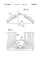
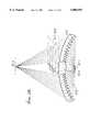
- FIG. 1is a vertical section in elevation showing one form of apparatus embodying the invention
- FIG. 2is a vertical section in elevation showing another form of apparatus embodying the invention
- FIG. 3is an enlarged section on lines 3--3 of FIG. 2;
- FIGS. 4a-4eare enlarged sections through elements of various configurations
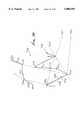
- FIG. 5is a view like FIG. 1 showing a portion of a solar optical concentrator of somewhat different and employed configuration
- FIG. 6is a schematic showing two devices, operating in conjunction, one of which is like that of FIG. 1 or 5, and the other being a collimator;
- FIG. 7is an enlarged section through a collimator as used in FIG. 6;
- FIGS. 8, 9, 10a, 10b, 11, 13, 14 and 15are schematics showing different applications of the radiant energy concentrating means
- FIGS. 12a and 12bare fragmentary sections showing modified concentrators
- FIGS. 16-18show various curved lens surface arrangements
- FIGS. 19a-19care sections producing light rays of varying angularity, as shown;
- FIG. 20is a section of a facet with three curved faces, illustrating the general principles of facet design
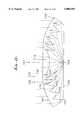
- FIG. 21is a section showing a further modified radiant energy concentrating means for use with a light-emitting diode
- FIG. 22is a section showing yet another modified radiant energy concentrating means made of silicon to pass infrared (IR) rays;
- FIG. 23is a section showing a radiant energy transmitting body means, as in FIG. 21a, directing converging light toward a light pipe;
- FIG. 24is a section showing a radiant energy transmitting means, directing diverging light as in a floodlight
- FIG. 25is a section showing a radiant energy transmitting means, directing light from a layer-stimulated sample to converge into a spectroscopic analyzer;
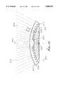
- FIG. 26is a section showing a radiant energy transmitting means, directing light from a toroidal source
- FIG. 27is a section like FIG. 25 but showing provision of a second lens, and a filter, in the path of collimated light or radiation;
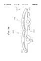
- FIG. 28is an enlarged perspective view of a TIR lens injecting light into a planar waveguide
- FIG. 29is a side view of a planar waveguide, with TIR lens facets at its edge, for injecting light from LEDs into the waveguide, and showing light from the waveguide illuminating a liquid crystal display;
- FIG. 30is a perspective view of linear TIR lens facets extending edgewise of a planar waveguide
- FIG. 31is like FIG. 30 but substitutes multiple discrete TIR lenses arrayed along an edge or edges of a planar waveguide;
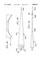
- FIG. 32is an edge view of an elongated waveguide with a TIR lens at one end thereof;
- FIG. 33is an enlarged endwise view of the FIG. 32 TIR lens.
- FIG. 34is a view like FIG. 32 showing the waveguide having an optical fiber or rod continuation.
- radiant energy transmitting body means 10in the shape of a cover or dome, has multiple facets or elements as at 11, each facet having an entry face to receive impingement of such radiation, an exit face to pass energy to the exterior of the body, and an internal reflection face angled relative to the entry and exit faces to reflect radiant energy incident on the reflection face toward the exit face.
- a selected facet 11has, in vertical cross section, an entry face 12 made up of stairstepped faces 12a and 12b, an exit face 13 facing the zone of target 15, and an internal reflection face 14.
- Radiant energysuch as light
- rays 16a and 16bentering the body means 10 at flat face 12a and normal thereto, and passing internally of the facet for reflection by face 14.
- face 14athe face may be silvered at 17.
- the reflected rays 16cthen pass toward and through exit face 13, normal thereto, and directly toward the target zone.
- the body means 10may consist of solid transparent material, such as glass or plastic, for example.
- the multiple facets 11 shown in FIG. 1may extend annularly about and define a common axis 18; or they may extend in parallel relation (normal to the plane of FIG. 1) at opposite sides of a plane as alternatively represented by 18, and which is normal to the plane of FIG. 1.
- corresponding points on the facetsdefine a concave surface, as for example at 21 (defined by the tips 22 of the facets closest the target), and characterized in that radiant energy passing through the exit faces is directed generally toward the target zone. Tips 22 are formed at the intersections of the faces 13 and 14.
- Surface 21is parabolic.
- the series of facets in FIG. 1is further characterized by the existence of tapered gaps 23 between adjacent faces 24 and 14 of the projecting portions of the facets. Faces 24 are inactive surfaces, i.e., do not pass the radiation. See for example representative rays 25 and 26 in FIG. 1. Ray 25 is redirected by its associated facet almost 90° toward the target, near the outer edge 27 of the TIR lens 10. Study of FIGS. 1 and 4 will show that angle ⁇ (the bend angle of the ray) increases for facets increasing in distance from axis or plane 18; and that angle ⁇ (the angularity of face 14 relative to a line or plane parallel to line or plane 18) increases for facets increasing in distance from 18. Also, the entry faces 12 form stairstep patterns.
- FIG. 1further shows a Fresnel lens 29 associated with TIR lens or body 10, and located at a mid-portion of the latter; thus Fresnel lens 29, which refracts incident radiant energy toward target 15, is located in the path of rays 30, which are redirected the least, i.e., at the smallest angles, toward the target.
- Lens 29may be integral with lens 10, for example.
- a reflector or mirror surfaceis shown at 30 spaced from and facing the facets at the target side thereof.
- Surface 30is arranged to reflect stray or divergent radiation from the extreme outward facets toward the target. See ray 31 in this regard, and reflection point 31a. This allows target 15 to halve the area exposed to heat loss that it would have without surface 30, since the bottom non-illuminated half could be well insulated.
- FIG. 1Also shown in FIG. 1 is one form of means to controllably tilt the assembly of lenses 10 and 29 and reflector 30 to cause axis 18 to remain directed toward a relatively moving source of radiation, as for example the sun.
- a base plate 32supports reflector 30, as well as the dome-shaped lens 10 and 29, via extreme outer edge portion 10a of the body means 10.
- a ring gear 33supports plate 32, and meshes with spur gear 34.
- Drive motor 35rotates gear 34 to controllably rotate ring gear 33, and control unit 36 controls motor 35.
- Unit 36is responsive to photocells 37 and 38 in such manner that the photocells remain directed toward the light source.
- the photocellsare suitably carried at 99 by the plate 32, as for example near its periphery.
- Target 15may for example comprise a fluid receptacle which is heat conductive, to transmit heat to fluid in the receptacle, as for example water in a pipe.
- the numerals 100 and 129designate lenses corresponding to lenses 10 and 29 described above. They are elongated in the direction of arrow 149 and are carried by supports indicated at 150 and 151. V-shaped shroud 152 has edge portions 152a connected to the opposite edges of lens body 100, so that the shroud and lenses define an enclosure.
- a second and insulative tubular shroud 153extends within that enclosure, about a tank 154 which has fixed (nonrotatable) position.
- a support for the tankmay take the form of legs indicated at 155 and 156, bearings being provided at 157 and 158 to allow tank and shroud rotation about central axis 159, along with the lens assembly.
- the shroud 153is cut-away at locations 160 and 161 to allow entry of radiant energy from the lens assembly, to be absorbed by the tank, while heated air is prevented from escaping gap 162 by wipers 163; the enclosure has a reflecting interior surface 152b.
- Cool liquidsuch as water
- enters the tank via pipe 164is heated therein, and discharges into the tank lower end at 164a.
- Warmed liquidslowly flows at 200 back up the tank, being further heated by contact with the exterior of pipe 164, the liquid leaving the tank at outlet 165.
- a sacrificial anode 166 in the water 200is adapted to corrode, electrolytically suppressing any corrosion of the tank itself.
- a back-up heater 167 in water 200is supplied with electrical current to heat water in the tank as when solar radiation is blocked or non-existent, as at night.
- An air-gapmay be provided at 162 between shroud 153 and the tank itself.
- Sun tracking mechanismis indicated at 170, to rotate the assembly to maintain the sun's rays incident normally toward the lenses 100 and 129, i.e., in direction 171 in FIG. 3.
- TIR facecan be in faceted slots on either side of the body means or on the walls of tunnels within the latter, while the entry faces can be on faceted steps or even on a completely smooth cover surface.
- tunnel 40forms TIR face 41, while exit face 42 has stairsteps 42a and 42b.
- slot 50is on the entry side of the body means, having TIR face 51 and entry face 54.
- Exit face 52has stairsteps 52a and 52b.
- tunnel 60forms TIR face 61, and entry face 62 and exit face 64 are on smooth continuous surfaces.
- TIR face 61must be longer than TIR faces 41 of FIG. 4a or 51 of FIG. 4b, because of the refractive bending of ray 63 by entry face 62.
- the length of a TIR face relative to facet width 65is:
- TIR LENGTHcos ⁇ /(cos ⁇ cos ⁇ ) where ⁇ is the incident angle of ray 63a with surface normal 66, ⁇ is the angle of the refracted ray 63b with 66, ⁇ the incident angle of reflected ray 63c with exit surface normal 67, and ⁇ the angle of refracted by 63d with 67.
- Snell's lawThe relationships of these angles are given by Snell's law:
- nis the index of refraction of the body means material.
- neighboring elementsmust be relatively positioned everywhere on or above a parabola with the target as its focus and a rim slope equal to half the rim angle (i.e., the redirective bend angle of the outermost elements).
- An alternative facet styleseeks to minimize such impingement losses by concentrating the rays before they strike the TIR face, which can thereby be smaller to reduce said impingement.
- Convex and concave entry and exit faceswill do this, though with some decrement of the cover's concentration ratio or acceptance angle, which for some applications is far outweighed by bringing the transparent redirecting means even closer to the target.
- FIG. 4eAnother method of widening the slots is the faceted exit face, shown in FIG. 4e.
- slot 70has been opened until it nearly impinges upon extreme ray 73b.
- Exit face 74has miniature stairsteps 74a and 74b, respectively normal to and parallel to reflected ray 73b.
- the particular manufacturing method and design applicationwill determine the place of transition to a Fresnel lens, or alternatively to a window, that passes rays to a small parabolic reflector below the target, which is thereby illuminated from a full circle of directions.
- Another possible configurationwould have the outer parts of the redirecting means sending radiant energy to a central target while the inner parts redirected energy to outer targets using only large bend angles throughout. All these configurations are derivatives of the basic method of this invention: upon multiple TIR-transmitting elements, properly placed entry, exit, and TIR faces redirect radiant energy to a predetermined target zone, or into a predetermined target solid angle.
- a cover means(as at 10 or 110) whose focal length can be shorter than any parabolic mirror with concentrations twice as high, but which is free from shading and presents a convex surface with lower aerodynamic drag than the concave parabolic mirror. Its target is near the center of gravity and closer to the ground than that of the parabolic reflector making fixed receiver means easier to design and maintain. Finally, the nearly 100% reflective efficiency of the TIR faces give much greater potential for high efficiencies than does the parabolic mirror.
- FIGS. 1 and 5it will be understood that the elements 11 and 311 join together, integrally and continuously, to form a radiant energy transmitting means in the general form of a cover.
- the latterhas an energy entry surface (top surface in FIG. 1, for example) and an exit surface (bottom surface in FIG. 1) lying on opposite sides of the cover.
- the covercauses radiant energy leaving the exit surface to have a generally different direction than the direction of energy incidence on the entry surface.
- multiple TIR facesare situated on the exit surface adjacent slots proximate the exit surface, as referred to above.
- the entry surfacehas a faceted stairstep configuration.
- the exit surface of the coverlies beyond and further from the target than a parabola (see 21 and 321).
- the covermay be constructed of transparent material, as for example plastic.
- FIG. 8schematically shows a means 410 corresponding to the means 10 of FIG. 1 or 310 of FIG. 5, or equivalent.
- a target zoneis shown at 415.
- a retro-reflector means 412is spaced behind and facing the target zone so as to redirect radiant energy upon the target zone. See ray 413.
- FIG. 9schematically shows a radiant energy source means (as for example a light source) at 430 at the target zone. Radiant energy emitted by the source means 430 is redirected by the body means 435 (like 10 or 310) in reverse relation. See ray 436.
- a radiant energy source meansas for example a light source
- FIGS. 10a and 10bshow two variations of a "uni-bend" lens with uniform facets extending annularly about a cylindrical target.
- all the facets 444 of conical body means 440bend rays 443 through 90° onto cylindrical target 441.
- flat body means 445has identical facets 448 bending rays 447 through 45° upon cylindrical target 446.
- FIG. 11shows a structural means 460 enclosing the space 461 behind the exit face of the cover means 459 (like 10 or 310), so that pressurization of the atmosphere of space 461 will hold the flexible cover means in its distended or circular shape, with center of curvature at point 426. See target zone 462, pressurization means such as a pump 463 and ray 464.
- pressurization meanssuch as a pump 463 and ray 464.
- a thin film 465adheres to the inside of cover means 459, having miniature sawtooth facets 467 as shown in the insert.
- FIG. 12ashows a plurality (two for example) of target zones 470 and 471 to receive radiant energy from the transmitting body means 472 (like 10 or 310).
- Each element 473redirects energy in a plurality of directions, toward the target zones.
- each element 473may be like element 10 or 310 described above but have a TIR face divided into two sub-faces 474 and 475 at slightly different angles to accomplish the reflection of the two rays 476 and 477, respectively directed by the faces 474 and 475 toward the two target zones.
- TIR face 453is the exit face for ray 451; while TIR face 454 is the exit face for ray 452.
- This symmetrical case of twin 60° bendsmay be varied to give two different right and left hand bends, with differing division of the incoming radiant energy.
- the cover means 480(like 10 or 310) has different groups of elements redirecting radiant energy toward different target zones.
- the elements at locus 481direct radiant energy toward target 482; and the elements at locus 483 direct energy toward target 484. See rays 485 and 486.
- cover or body means 510corresponds to 10 or 310 described above.
- a secondary radiant energy redirecting meansis provided at 520 to intercept the radiant energy from body 510 and to redirect it. See rays 521 with segments 521a falling on body 510; redirected segments 521b falling on body 520; and secondarily redirected segments 521c transmitted by body 520.
- FIG. 7shows body 520 in detail, with entry faces 530, exit faces 531, and TIR faces 532.
- the rays 521care parallel, in this instance, i.e., collimated, so that means 520 may be regarded as a collimator.
- the means 550 shown in FIG. 14is like 10 and 300, except that the exit faces 551 are individually angled relative to radiant energy passing through them, so as to cause reflective redirection of the radiant energy. See beam 552 refracted at face 551. Also in FIG. 14, the exit faces 551 may be considered to refractively redirect radiant energy in partial opposition to the redirection by the TIR faces 553, the latter extending at less steep angles (than in FIGS. 1 and 5) so as to widen the slots 554. Note also in FIG.
- entry faceis smooth and unfaceted, at 556, and that exit face 551 is parallel to refracted ray 552b, giving the maximum backbend and the lowest possible slope of entry surface 556, which in fact is lower than the parabola 321 or the quarter-circle 325 in FIG. 5.
- the body means 560is like that at 10 or 310, except that it utilizes the variation index of refraction that varies with the wavelength of the radiant energy, so as to constitute a wavelength separating, radiating energy redirecting, transmitting body means.
- Two target zones 561 and 562are shown, and are spaced apart to receive different wavelengths of the wavelength separated, redirected, radiant energy. See incident ray 563 which separates into ray 563a of one wavelength directed toward target 561, and ray 563b of another wavelength directed toward target 562.
- either targetmay be considered as a means to convert radiant energy to electricity.
- One such meansis a photovoltaic cell.
- Such a devicemay be located at the target zones in FIGS. 1 and 5.
- one targetmay comprise a photoillumination means receiving visible wavelengths; and the other target may comprise a thermal receiver receiving invisible wavelengths at zone 561.
- the visible wavelength rayswill follow the reverse path of rays 563, i.e., be collimated, while the invisible longer wavelength heat rays will be diverged more outward from the visible beam, so that spotlights on actors will not subject them to a heat load several times greater than that of the visible radiation.
- FIGS. 1-15Certain aspects of FIGS. 1-15 were also discussed in prior U.S. Pat. No. 4,337,759.
- FIG. 16may be considered to correspond generally to FIG. 4a or FIG. 4b, i.e., to present a lens body 600 having an entry face 601, a TIR face 602, and an exit face 603 on the body 600.
- Such faces 601 and 603may be faceted, as in the styles shown in FIGS. 1, 3, 7, 8, 9, 10, and 13. Rather than all such faces being flat, face 601 is convexly curved, away from the body 600, as shown; whereas faces 602 and 603 are flat, as previously described.
- Diverging entry rays 605are refracted at 605a for reflection at 605b, and travel at 605c toward face 603. The rays pass through exit face 603 and are in general refracted to travel externally at 605d, as shown. If exit face 603 was convexly curved, then rays 605d could be converging.
- the curvature of entry face 601eliminates the divergence and keeps any rays from missing TIR face 602.
- entry face 611is flat, as is exit face 613; however, TIR face 612 is concave toward the incident ray side of that face, as shown.
- Diverging entry rays 615pass through face 611 and travel at 615a, within body 610, for reflection at 615b, at different points and angles, for travel at 615c toward face 613.
- the rayspass through that face, and are in general refracted, and travel externally at 615d, as shown.
- the curvature of the TIR face 612has made rays 615d parallel, while restricting the amount of exit face 613 that is used, enabling the entire lens to have a higher profile.
- entry face 621is flat, as is TIR face 622; however, exit face 623 is concave away from the body 620, i.e., away from TIR face 622, as shown.
- Entry rays 625which may be parallel, pass through face 621 and travel at 625a, within body 620, for reflection at 625b at different points and angles, for travel at 625c toward face 623. The rays then pass through that face and are in general refracted to travel externally at 625d, as shown. Exit face 623 is fully flashed, as would be desirable for a converging TIR lens.
- the bodies 650, 660 and 670are closely similar to body 740 shown and described in FIG. 21.
- the angularities of the annular facetsare slightly varied, so that the body 660 produces collimated light rays 664; body 650 produces converging light rays at 654; and a body 670 produces diverging light rays 674.
- the light source in each caseis shown at 680.
- the top surface 659, 669, and 679 of the lensis circularly curved in the section shown, or spherically curved for an annular lens.
- lens body 700acts as a converging TIR lens, in the same manner as lens 650 in FIG. 19a. Its performance is superior because of its full flashing, which gives more effective focusing, and higher profile, and which leads to smaller angular magnification of the light source, and a smaller focal spot.
- Upper light ray 701 and lower light ray 702are the defining rays for the calculation of the angles of the boundaries of facet 703 and of the position of inwardly adjacent facet 704. The slope of lens profile line 705 is to be maximized.
- the defining raysare generally diverging but can come from different parts of the light source; for example, upper ray 701 comes from the bottom of the light source, while lower ray 702 comes from the top of the light source, so that they constitute the extreme rays of all light emitted by the source.
- the facet-defining upper and lower raysare not the extreme rays of the light source, then some fraction of its output light will be redirected by the lens into the output rays. Such a case may occur if there is a tradeoff between this fraction and the tightness of the focusing, to be resolved by the particular application of the lens.
- Facet 703is defined by notch 703n (shown here as a fillet), tip 703t, upper point 703u of entry face 706, and on exit face 707, outer point 706o and inner point 706i.
- Inwardly adjacent facet 704provides three limiting points that act analogously to pupils of conventional optical systems: tip 704t defines upper ray 701, while both notch 704n and outer exit face 704o must be cleared by lower ray 702.
- the convex curvature of entry face 706accommodates the divergence of the defining rays by assuring that upper ray 701 does not miss TIR face 708 and that lower ray 702 does miss notch 704n.
- exit face 707is relatively close to TIR face 708.
- a thicker lens with a more distant exit facewould employ convex curvature (as on the TIR face 708c) to assure that the defining rays do not miss the edges of exit face 707. If they did miss, they would not be lost, since they would totally internally reflect on riser faces 709 or 710, and enter the lens output with only modest angular errors.
- Riser face 709is angled to just clear lower ray 702, after it has left the lens.
- Optically inactive face 711is kept at a minimum draft angle determined by the manufacturing method (for injection molds, it is typically 2° off the mold-pulling direction). Face 711 assists maximizing of lens profile by enabling entry face 706 to be angled more downward than is the case with lens 650 of FIG. 19a, where there is a straight line between a facet tip and the notch of the inwardly adjacent facet.
- a unique determination of the four angularities of the facetrequires four conditions: (1) overall bend angle; (2) upper ray falling on the TIR face; (3) lower ray clearing notch of the inwardly adjacent face; and (4) lower ray clearing the outer edge of exit facet of the inwardly adjacent facet.
- the curvatures of the three optically active faces of the facetare individually determined:
- entry-face curvaturehelps to maximize the slope of the lens profile line, by allowing the tip of the inwardly adjacent facet to rise while keeping the higher upper ray from missing the TIR face (this reduces the divergence of the output light of the inner facets of the lens by increasing their height above the source);
- TIR-face curvaturealso helps to maximize lens slope by allow the notch of the inwardly adjacent facet to rise; in addition, TIR-face curvature enables the exit face to be fully flashed, an important characteristic for several illumination applications;
- exit-face curvatureminimizes the size of the focal spot of converging TIR lenses, and minimizes the beam divergence of collimating TIR lenses.
- Non-circular profiles of these curved facesmay be selected in order to provide uniform illumination by the facet.
- the axis of the annular, radiant energy transmitting body 740appears at 751.
- the bodyhas multiple annular facets 742 to 746 which are generally concentrically arranged but having tips 742d to 746d progressively closer to plane 750 normal to axis 751.
- Face 742a of facet 742is convex toward face 742b; and face 742b is concave toward face 742a in the section shown. This relationship obtains for other facets, as shown.
- a light-emitting diode (LED) 758is located at the intersection of plane 750 with axis 751 and emits light rays toward the body 740.
- Ray 753passes through face 742a, is refracted toward TIR face 742b and is reflected toward and passes through upper flat face 748. See also ray 752 passing through face 743a, reflecting at TIR face 743b, and passing through upper face 748a, angled as shown. All rays passing upwardly beyond faces 748 and 748a are collimated.
- the transverse width of the body 740may be from 0.12 to one inch, for example, and the transparent body 740 may consist of molded plastic material.
- a refractive section without facetsappears at 719. Smaller ratios of lens diameter to LED size may have outermost facets large, and successively inward facets smaller, in order to have a higher lens profile and better collimation curved facets are necessary for.
- the radiant energy transmitting body 760may have the same general construction as shown in FIGS. 20 and 21.
- the lens body 760consists of silicon, or a similar material, for passing infrared rays, but blocking visible light rays, while transmitting infrared rays.
- An arc lamp radiant energy sourceis shown at 764, at the same position as the LED in FIG. 20.
- a reflector surface 765may be employed to extend in plane 766 corresponding to plane 750 in FIG. 21 with a parabolic section 762.
- the infrared rays emanating at 767are typically collimated but may be divergent or convergent, as in FIGS. 19a and 19c.
- unfaceted central section 770refracts rays, as shown.
- the arc light source at 764may be produced by anode and cathode elements 764a and 764b.
- Top exit surface 759is circularly curved in the section shown; but the lens may have external, stairstep faceting.
- Protective transparent envelope 769keeps outside air away from the arc.
- the body means 780may have the same or similar construction as that of FIG. 19a, for producing and directing convergent light at 781 into the entrance end 782 of a light pipe 783.
- the lenshas an upwardly convex arcuate upper exit surface or face 785, an entrance face or faces 786, and a TIR face or faces 787. Faces 786 and 787 taper downwardly toward plane 790, corresponding to plane 710 in FIG. 21.
- a central light source 788is positioned in the manner of the LED in FIG. 21.
- a planar back mirror 789extends in plane 790 corresponding to plane 710 and faces upwardly. This device may input up to 80% of the light into pipe 783, rather than 10% of the light as via a conventional ellipsoidal reflector.
- the body means 800may have the same or similar construction as that of FIG. 21c.
- Circularly curved top surface 801is curved downwardly.
- the lens axisin the case of an annular set of facets, is indicated at 802. Facets are seen from 803 to 812.
- a typical annular facet 809has an entrance face 809a and a TIR face 809b. Note ray 820 path passing through face 809a and face 801, and totally reflected at face 809b. In the section shown, each of the faces 809a and 809b is flat. All entry faces have draft in the direction 822, for ease of molding.
- the lensis transparent and may consist of molded plastic material.
- a light source 825is located on axis 802, and just above the plane 826, is within the confines of the hollow lens, as in the above examples; and the rays 827 emanating from face 802 diverge, as in a floodlight application.
- the circular section half-angle subtended by the surface 801is typically less than 45° and greater than 25°, and is typically about 35°.
- lens body 850is the same as that of FIG. 21a, except that the central refractive means has been replaced by microscope objective 854, which can slide axially inside the lens to focus on sample 851.
- Characteristic diffuse (i.e., in all directions) emission 856 from sample 851is collected by lens 850 and focused on analyzer entrance slit 852.
- Collimated laser beam 855is reflected by mirror 853 into objective 854 and focused on sample 851.
- Mirror 853is removable in order to use microscope objective 854 to view sample 851 and exactly adjust its position.
- Lens body 850could extend downward below sample 851 to collect even more of the diffuse emission.
- Sample 851may be a glass capillary containing a gas or liquid, a gold hemisphere coated with a sample substance, an integrated circuit on a production line (checking material composition or contamination), or a biological tissue sample.
- lens body 860has a cross-section with axis 863, in order to accommodate toroidal (typically fluorescent) light source 861.
- Beneath this lampis annular involute reflector 862, with disc-shaped, planar mirror section 864 inside it and annulus mirror 865 outside it.
- Annular lens 866refracts ray 868, which was reflected from involute 862.
- Ray 869is exactly analogous to ray 820 in FIG. 24.
- Ray 867is redirected by facet 870.
- the overall device of lamp, lens, and reflectorcomprise a compact floodlamp that offers much narrower divergence and much higher efficiency than possible with the prior art of reflector design.
- the lens body 950is the same as shown in FIG. 19b or as in FIG. 25, modified to collimate light or a laser beam, supplied as indicated at 955.
- a light source or light-emitting target (laser for example) 951transmits light to faceted side of the TIR lens body 950, the latter redirecting the light rays, as shown by the broken lines 956 and 980, to pass through first refracting lens means at surface 950a and emerge as collimated light at 955.
- Such lightthen impinges on and passes through the wavelength selective filter 982 and then through a second lens means 983 indicated in the example as a focusing Fresnel lens.
- the latterredirects or focuses light at 984 onto the sample, or an analyser, 952.
- a wavelength-selective filter 982is used to remove passively scattered light of the collimated laser beam 955, while allowing passage of fluorescence wavelengths, such as those generated in Raman spectroscopy, for stimulated emissions at 952.
- the filter 982extends in a plane normal to principal axis 986 defined by the lens 950 and by lens 983, the filter requiring normal incidence of light for good wavelength selection, since the filter wavelength depends upon the angle of incidence.
- the filtertypically removes the laser wavelengths.
- the auxiliary or second lens means 983can also act to reduce any aberrations introduced by the annular TIR lens 950.
- a microscope objective lens 954which can slide axially in a bore in lens 950, and focus auxiliary source light 965 onto the target or laser 951.
- a means to adjustably move objective lens 954 axiallyis schematically shown at 968.
- Auxiliary source light 965may be redirected by mirror 953, as shown, toward lens 954, for focusing onto the target 951.
- a linear TIR lens 1027is elongated in direction 1028, as are the lens facets 1027a.
- An elongated light sourceis indicated at 1029, along the focal line 1029a.
- a planar mirror 1030extends across the faceted side of the lens, and reflects backlight from the source toward the facets.
- the exit side or face of the lensis coupled to a waveguide 1025, as better shown in FIG. 29; and light is injected in direction 1026 edgewise into the waveguide.
- the lensmay be integral with the waveguide, or attached to its edge, as indicated by plane 1040 in FIG. 29.
- FIG. 29also incorporates known optical means, indicated here by a reflector 1025a, to redirect light 90° in the planar waveguide, as shown by arrows 1070.
- a liquid crystal displayis shown at 1042 at the upper side of the flat, planar waveguide, and may be used for the screen of a portable computer.
- the TIR lens facetsfulfill two functions:
- the central Fresnel facets of the linear lensare in this case are replaced by a concave cylinder seen at 1027c, for those rays of the source that can directly pass into the waveguide.
- FIG. 30shows in perspective the elongated TIR lens extending along the sides of the planar waveguide. See lens elongated sections 1027 and 1027', oriented at 90° to one another.
- the waveguidemay consist of plastic, such as acrylic, as shown at 1027d. Light from the lens sections travels in the waveguide in directions indicated by arrows 1038 and 1039.
- this configurationis especially suitable for use with light-emitting diodes (LEDs), which are very small and can be placed on the focal line of the linear lens. In this way, the light of red, green, and blue LEDs will be mixed to a uniform white.
- LEDslight-emitting diodes
- the three groups of LEDsmay be separately triggered, so that only those of one color are emitting light at any one time, for sequential-color liquid crystal displays, which have three times the spatial resolution of conventional color displays.
- FIG. 30shows, by way of example, red, green, and blue LEDS, in repeated groups, and identified as follows:
- a control 1055is connected to the LEDs via the illustrated leads, to control ON-OFF states, whereby color control at the upper side of the waveguide panel is achieved.
- FIG. 31illustrates a rectangular and planar waveguide 1063, similar to waveguide 1025. It is illuminated along two of its edges 1063a and 1063b, which extend at 90° relative to one another.
- the illumination sourcesare circular TIR lenses 1060, as described above, but made integral with the waveguide edges, as by embossing.
- Each lenshas its own light source, indicated at 1064.
- the annular facets of the lensesface outwardly, i.e., away from the waveguide, but are not illustrated in this view. (See, however, circular TIR lens and their facets, discussed and shown above.)
- FIGS. 32-34show a waveguide 1069 that tapers endwise, away from the TIR lens 1071, coupled to the waveguide.
- a light source 1080emits light toward the faceted side of the TIR lens 1071.
- Tapered rod 1069serves to conduct and to spread light out into the full angular range ⁇ f carried by the plastic fiber 1069b. This range is typically 30°. The amount of taper depends upon the angular range ⁇ L of the light leaving the facets (typically up to 10°), which is in turn determined by the ratio of lens diameter to source size. The lens diameter d L and fiber diameter d f are related by
- n crefractive index n f of the fiber.
- this form of the inventionprovides efficient coupling of an LED's radiation into a multi-mode optical fiber, for a variety of purposes, both in illumination, as shown here, and communication, where LEDs are already in wide use.
- this configurationcan be used for any light source, such as small incandescent lamps, that is much smaller than a fiber's diameter.
- FIG. 33shows the TIR lens 1071 in greater detail.
- Numeral 1081indicated a reflector in FIG. 32.
Landscapes
- Physics & Mathematics (AREA)
- General Physics & Mathematics (AREA)
- Optics & Photonics (AREA)
- Engineering & Computer Science (AREA)
- General Engineering & Computer Science (AREA)
- Life Sciences & Earth Sciences (AREA)
- Sustainable Development (AREA)
- Sustainable Energy (AREA)
- Chemical & Material Sciences (AREA)
- Combustion & Propulsion (AREA)
- Mechanical Engineering (AREA)
- Thermal Sciences (AREA)
- Health & Medical Sciences (AREA)
- Toxicology (AREA)
- Lenses (AREA)
Abstract
Description
sin η=n sin δ, and sin λ=n sin κ
______________________________________ flat convex concave ______________________________________ entry face x exit face x TIR face x B entry face x exit face x TIR face x C entry face x exit face x TIR face x ______________________________________
______________________________________ LED emitted light color ______________________________________ 1052 red 1053 green 1054 blue ______________________________________
d.sub.L sin Θ.sub.L =d.sub.F sin Θ.sub.F
N.A.=sin Θ.sub.F =√(n.sub.f.sup.2 -n.sub.c.sup.2)
Claims (20)
Priority Applications (1)
| Application Number | Priority Date | Filing Date | Title |
|---|---|---|---|
| US08/472,288US5806955A (en) | 1992-04-16 | 1995-06-07 | TIR lens for waveguide injection |
Applications Claiming Priority (3)
| Application Number | Priority Date | Filing Date | Title |
|---|---|---|---|
| US07/869,003US5404869A (en) | 1992-04-16 | 1992-04-16 | Faceted totally internally reflecting lens with individually curved faces on facets |
| US08/415,274US5577492A (en) | 1992-04-16 | 1995-04-07 | Collimating TIR lens with focusing filter lens |
| US08/472,288US5806955A (en) | 1992-04-16 | 1995-06-07 | TIR lens for waveguide injection |
Related Parent Applications (1)
| Application Number | Title | Priority Date | Filing Date |
|---|---|---|---|
| US08/415,274Continuation-In-PartUS5577492A (en) | 1992-04-16 | 1995-04-07 | Collimating TIR lens with focusing filter lens |
Publications (1)
| Publication Number | Publication Date |
|---|---|
| US5806955Atrue US5806955A (en) | 1998-09-15 |
Family
ID=27022933
Family Applications (1)
| Application Number | Title | Priority Date | Filing Date |
|---|---|---|---|
| US08/472,288Expired - LifetimeUS5806955A (en) | 1992-04-16 | 1995-06-07 | TIR lens for waveguide injection |
Country Status (1)
| Country | Link |
|---|---|
| US (1) | US5806955A (en) |
Cited By (172)
| Publication number | Priority date | Publication date | Assignee | Title |
|---|---|---|---|---|
| US5969343A (en)* | 1995-08-24 | 1999-10-19 | Matsushita Electric Industrial Co., Ltd. | Linear illumination device |
| US5997148A (en)* | 1997-06-04 | 1999-12-07 | Enplas Corporation | Surface light source device of side light type |
| US6210425B1 (en) | 1999-07-08 | 2001-04-03 | Light Sciences Corporation | Combined imaging and PDT delivery system |
| US6268600B1 (en) | 1994-08-01 | 2001-07-31 | Matsushita Electric Industrial Co., Ltd. | Linear illumination device |
| US6371623B1 (en)* | 1999-08-16 | 2002-04-16 | Minebea Co., Ltd. | Spread illuminating apparatus with a means for controlling light directivity |
| US20020048163A1 (en)* | 2000-07-13 | 2002-04-25 | Hisanori Kawakami | Light source device, illumination device liquid crystal device and electronic apparatus |
| US20020101729A1 (en)* | 2000-11-24 | 2002-08-01 | Nec Corporation | Lighting device, liquid crystal display device including the same, and method of fabricating the same |
| WO2002046806A3 (en)* | 2000-12-06 | 2002-08-15 | Dainippon Printing Co Ltd | Fresnel lens and die for the same |
| US20020191920A1 (en)* | 2001-06-14 | 2002-12-19 | Schladenhauffen Mark S. | Multiple viewing angle cover having integral light pipe |
| US20020198576A1 (en)* | 1999-01-15 | 2002-12-26 | James Chen | Patient portable device for photodynamic therapy |
| US20030085642A1 (en)* | 2001-07-20 | 2003-05-08 | Pelka David G. | Fluorescent light source |
| RU2207604C1 (en)* | 2002-07-22 | 2003-06-27 | Государственное образовательное учреждение Кубанский государственный университет | Input-output device of optical radiation to channel waveguide |
| US6597499B2 (en) | 2001-01-25 | 2003-07-22 | Olympus Optical Co., Ltd. | Total internal reflection fluorescence microscope having a conventional white-light source |
| US6598998B2 (en) | 2001-05-04 | 2003-07-29 | Lumileds Lighting, U.S., Llc | Side emitting light emitting device |
| US6603243B2 (en) | 2000-03-06 | 2003-08-05 | Teledyne Technologies Incorporated | LED light source with field-of-view-controlling optics |
| US20030147261A1 (en)* | 2002-01-03 | 2003-08-07 | Victor Babbitt | Liquid light guide system for interior lighting |
| US6637924B2 (en) | 2000-11-15 | 2003-10-28 | Teledyne Lighting And Display Products, Inc. | Strip lighting apparatus and method |
| US6679621B2 (en) | 2002-06-24 | 2004-01-20 | Lumileds Lighting U.S., Llc | Side emitting LED and lens |
| US20040057234A1 (en)* | 2002-09-19 | 2004-03-25 | Ferenc Mohacsi | High-intensity directional light |
| US20040070855A1 (en)* | 2002-10-11 | 2004-04-15 | Light Prescriptions Innovators, Llc, A Delaware Limited Liability Company | Compact folded-optics illumination lens |
| US6744960B2 (en) | 2000-03-06 | 2004-06-01 | Teledyne Lighting And Display Products, Inc. | Lighting apparatus having quantum dot layer |
| US20040105171A1 (en)* | 2002-12-02 | 2004-06-03 | Light Prescriptions Innovators, Llc, A Delaware Limited Liability Company | Asymmetric TIR lenses producing off-axis beams |
| US20040109664A1 (en)* | 2002-07-26 | 2004-06-10 | Advanced Display Inc. | Planar light source device and liquid crystal display device using the same |
| US20040170373A1 (en)* | 2003-02-18 | 2004-09-02 | Kim Jae Bum | Backlight unit |
| US20040189933A1 (en)* | 2002-12-02 | 2004-09-30 | Light Prescription Innovators, Llc | Apparatus and method for use in fulfilling illumination prescription |
| US20040228131A1 (en)* | 2003-05-13 | 2004-11-18 | Light Prescriptions Innovators, Llc, A Delaware Limited Liability Company | Optical device for LED-based light-bulb substitute |
| US20040264854A1 (en)* | 2003-06-30 | 2004-12-30 | Honeywell International Inc. | High speed optical system |
| US20050007751A1 (en)* | 2003-07-11 | 2005-01-13 | Kun-Jung Tsai | Illuminated logo unit with light guide plate |
| US20050024744A1 (en)* | 2003-07-29 | 2005-02-03 | Light Prescriptions Innovators, Llc | Circumferentially emitting luminaires and lens-elements formed by transverse-axis profile-sweeps |
| US20050063197A1 (en)* | 2003-08-07 | 2005-03-24 | Nightingale John L. | System and method utilizing guided fluorescence for high intensity applications |
| US20050086032A1 (en)* | 2003-07-28 | 2005-04-21 | Light Prescriptions Innovators, Llc | Three-dimensional simultaneous multiple-surface method and free-form illumination-optics designed therefrom |
| US20050092360A1 (en)* | 2003-10-30 | 2005-05-05 | Roy Clark | Optical concentrator for solar cell electrical power generation |
| US6899723B2 (en) | 1999-01-15 | 2005-05-31 | Light Sciences Corporation | Transcutaneous photodynamic treatment of targeted cells |
| US20050129358A1 (en)* | 2003-02-04 | 2005-06-16 | Light Prescriptions Innovators, Llc A Delaware Limited Liability Company | Etendue-squeezing illumination optics |
| US20050225988A1 (en)* | 2003-05-13 | 2005-10-13 | Light Prescriptions Innovators, Llc | Optical device for LED-based lamp |
| US20050231974A1 (en)* | 2004-04-14 | 2005-10-20 | Marvin Ruffin | Multiple LED focused lighting device |
| US20060044820A1 (en)* | 2004-08-31 | 2006-03-02 | Marvin Ruffin | Optic fiber LED light source |
| US20060138437A1 (en)* | 2004-12-29 | 2006-06-29 | Tien-Fu Huang | Lens and LED using the lens to achieve homogeneous illumination |
| US7149383B2 (en) | 2003-06-30 | 2006-12-12 | Finisar Corporation | Optical system with reduced back reflection |
| US20060283497A1 (en)* | 2005-06-16 | 2006-12-21 | Hines Braden E | Planar concentrating photovoltaic solar panel with individually articulating concentrator elements |
| WO2006116982A3 (en)* | 2005-04-29 | 2007-03-22 | Martin Roehrig | Plate-shaped light guiding body |
| US20070074582A1 (en)* | 2005-09-30 | 2007-04-05 | Santos Roberto S | Sensor mounting structure with adjustable swivel ball and panel mounting mechanism |
| US20070074592A1 (en)* | 2005-09-30 | 2007-04-05 | Santos Roberto S | Sensor mounting structure allowing for adjustment of sensor position |
| US20070074583A1 (en)* | 2005-09-30 | 2007-04-05 | Santos Roberto S | Sensor mounting structure with snapping feature |
| US20070074591A1 (en)* | 2005-09-30 | 2007-04-05 | Santos Roberto S | Sensor mounting structure with light pipe |
| US20070102037A1 (en)* | 2005-10-04 | 2007-05-10 | Irwin Philip C | Self-powered systems and methods using auxiliary solar cells |
| US20070109790A1 (en)* | 2003-10-31 | 2007-05-17 | Phoseon Technology, Inc. | Collection optics for led array with offset hemispherical or faceted surfaces |
| US20070188876A1 (en)* | 2006-01-17 | 2007-08-16 | Hines Braden E | Hybrid primary optical component for optical concentrators |
| US20070193620A1 (en)* | 2006-01-17 | 2007-08-23 | Hines Braden E | Concentrating solar panel and related systems and methods |
| EP1152186B1 (en)* | 2000-05-02 | 2007-12-19 | Robert Bosch Gmbh | Display illumination device |
| US20080061310A1 (en)* | 2006-09-07 | 2008-03-13 | Hong Kong Applied Science and Technology Research Institute Company Limited | Light emitting diode device, and manufacture and use thereof |
| WO2008046786A1 (en)* | 2006-10-20 | 2008-04-24 | Osram Gesellschaft mit beschränkter Haftung | Lamp module for projectors |
| US20080128586A1 (en)* | 2006-10-13 | 2008-06-05 | Johnson Richard L | Sun sensor assembly and related method of using |
| US20080135096A1 (en)* | 2006-09-30 | 2008-06-12 | Johnson Richard L | Optical concentrators having one or more line foci and related methods |
| CN100407008C (en)* | 2005-02-26 | 2008-07-30 | 三星电子株式会社 | Linear side emitters, backlight systems and liquid crystal displays using them |
| WO2007146033A3 (en)* | 2006-06-07 | 2008-10-02 | Pursuit Engineering Llc | Long-range illuminator using multiple radiation dispersion angles |
| US20080272383A1 (en)* | 2007-05-04 | 2008-11-06 | Loh Ban P | Side mountable semiconductor light emitting device packages, panels and methods of forming the same |
| US20080271776A1 (en)* | 2007-05-01 | 2008-11-06 | Morgan Solar Inc. | Light-guide solar panel and method of fabrication thereof |
| US20090000662A1 (en)* | 2007-03-11 | 2009-01-01 | Harwood Duncan W J | Photovoltaic receiver for solar concentrator applications |
| US20090064993A1 (en)* | 2007-09-10 | 2009-03-12 | Banyan Energy, Inc. | Solar energy concentrator |
| US20090079825A1 (en)* | 2007-09-26 | 2009-03-26 | Honeywell International, Inc. | Pseudo-color covert night vision security digital camera system |
| US20090080198A1 (en)* | 2007-06-29 | 2009-03-26 | Dialight Lumidrives Limited | Spatial luminance |
| US20090101829A1 (en)* | 2007-10-19 | 2009-04-23 | Nordson Corporation | Sensor, system, and method for an ultraviolet lamp system |
| US7559672B1 (en) | 2007-06-01 | 2009-07-14 | Inteled Corporation | Linear illumination lens with Fresnel facets |
| US20090190347A1 (en)* | 2008-01-25 | 2009-07-30 | Rudiger Lanz | Motor-driven, head-displaceable floodlight unit |
| US20090225529A1 (en)* | 2008-02-21 | 2009-09-10 | Light Prescriptions Innovators, Llc | Spherically emitting remote phosphor |
| US20100188602A1 (en)* | 2009-01-28 | 2010-07-29 | Sharp Laboratories Of America, Inc. | Area active backlight with steerable light source |
| US20100188610A1 (en)* | 2009-01-28 | 2010-07-29 | Sharp Laboratories Of America, Inc. | Area active backlight with steerable light source |
| US20100231498A1 (en)* | 2009-03-13 | 2010-09-16 | Microsoft Corporation | Image display via multiple light guide sections |
| US7798675B2 (en) | 2006-08-11 | 2010-09-21 | Light Prescriptions Innovators, Llc | LED luminance-enhancement and color-mixing by rotationally multiplexed beam-combining |
| US7806547B2 (en) | 2006-07-14 | 2010-10-05 | Light Prescriptions Innovators, Llc | Brightness-enhancing film |
| US20100278480A1 (en)* | 2009-04-21 | 2010-11-04 | Vasylyev Sergiy V | Light collection and illumination systems employing planar waveguide |
| WO2010143112A1 (en)* | 2009-06-11 | 2010-12-16 | Koninklijke Philips Electronics N.V. | Illumination apparatus |
| US20110011449A1 (en)* | 2007-05-01 | 2011-01-20 | Morgan Solar Inc. | Light-guide solar panel and method of fabrication thereof |
| US20110043142A1 (en)* | 2009-08-21 | 2011-02-24 | Microsoft Corporation | Scanning collimation of light via flat panel lamp |
| US20110044582A1 (en)* | 2009-08-21 | 2011-02-24 | Microsoft Corporation | Efficient collimation of light with optical wedge |
| US7925129B2 (en) | 2007-09-10 | 2011-04-12 | Banyan Energy, Inc. | Compact optics for concentration, aggregation and illumination of light energy |
| US20110148270A1 (en)* | 2009-12-21 | 2011-06-23 | Malek Bhairi | Spherical light output LED lens and heat sink stem system |
| US7982823B1 (en)* | 2010-06-17 | 2011-07-19 | Sharp Laboratories Of America, Inc. | Area active backlight with steerable backlight |
| US20110188244A1 (en)* | 2009-05-25 | 2011-08-04 | Sung Ho Hong | Gap member, lens and lighting device having the same |
| US8075147B2 (en) | 2003-05-13 | 2011-12-13 | Light Prescriptions Innovators, Llc | Optical device for LED-based lamp |
| EP2287640A3 (en)* | 2009-05-25 | 2012-02-15 | LG Innotek Co., Ltd. | Gap member, lens and lighting device having the same |
| DE102010034020A1 (en)* | 2010-08-11 | 2012-02-16 | Fraunhofer-Gesellschaft zur Förderung der angewandten Forschung e.V. | Surface structure and Fresnel lens and tool for producing a surface structure |
| EP2428724A1 (en) | 2010-09-08 | 2012-03-14 | SMR Patents S.à.r.l. | Optimal light coupling for rear view devices |
| US20120155841A1 (en)* | 2010-12-15 | 2012-06-21 | William Marsh Rice University | Generating a heated fluid using an electromagnetic radiation-absorbing complex |
| US8242350B2 (en) | 2008-05-16 | 2012-08-14 | Cashion Steven A | Concentrating photovoltaic solar panel |
| US8328403B1 (en) | 2012-03-21 | 2012-12-11 | Morgan Solar Inc. | Light guide illumination devices |
| CN102954360A (en)* | 2011-08-22 | 2013-03-06 | 海洋王照明科技股份有限公司 | Adjustable condensed light and floodlight lamp holder and lamp |
| US8393777B2 (en) | 2005-07-28 | 2013-03-12 | Light Prescriptions Innovators, Llc | Etendue-conserving illumination-optics for backlights and frontlights |
| US8412010B2 (en) | 2007-09-10 | 2013-04-02 | Banyan Energy, Inc. | Compact optics for concentration and illumination systems |
| US8419232B2 (en) | 2005-07-28 | 2013-04-16 | Light Prescriptions Innovators, Llc | Free-form lenticular optical elements and their application to condensers and headlamps |
| WO2013054220A3 (en)* | 2011-10-11 | 2013-06-13 | Koninklijke Philips Electronics N.V. | Lighting apparatus |
| CN102272537B (en)* | 2008-11-12 | 2013-09-04 | 阿文戈亚太阳能新技术公司 | Light collection and concentration system |
| WO2013160823A1 (en)* | 2012-04-26 | 2013-10-31 | Koninklijke Philips N.V. | Lighting arrangement |
| US8631787B2 (en) | 2005-07-28 | 2014-01-21 | Light Prescriptions Innovators, Llc | Multi-junction solar cells with a homogenizer system and coupled non-imaging light concentrator |
| US8705914B2 (en) | 2007-09-10 | 2014-04-22 | Banyan Energy, Inc. | Redirecting optics for concentration and illumination systems |
| WO2014120925A1 (en) | 2013-01-30 | 2014-08-07 | Cree, Inc. | Optical waveguide assembly and light engine including same |
| US8854799B2 (en) | 2012-03-02 | 2014-10-07 | Microsoft Corporation | Flux fountain |
| US8873227B2 (en) | 2012-03-02 | 2014-10-28 | Microsoft Corporation | Flexible hinge support layer |
| US8885995B2 (en) | 2011-02-07 | 2014-11-11 | Morgan Solar Inc. | Light-guide solar energy concentrator |
| US20140355302A1 (en)* | 2013-03-15 | 2014-12-04 | Cree, Inc. | Outdoor and/or Enclosed Structure LED Luminaire for General Illumination Applications, Such as Parking Lots and Structures |
| US20140376208A1 (en)* | 2013-06-19 | 2014-12-25 | Samsung Display Co., Ltd. | Optical structure and backlight unit |
| US8947353B2 (en) | 2012-06-12 | 2015-02-03 | Microsoft Corporation | Photosensor array gesture detection |
| US20150109820A1 (en)* | 2013-03-15 | 2015-04-23 | Cree, Inc. | Outdoor and/or Enclosed Structure LED Luminaire |
| US9075566B2 (en) | 2012-03-02 | 2015-07-07 | Microsoft Technoogy Licensing, LLC | Flexible hinge spine |
| US20150219308A1 (en)* | 2012-08-23 | 2015-08-06 | Koninklijke Philips N.V. | Lighting device with a LED and an improved reflective collimator |
| US9201185B2 (en) | 2011-02-04 | 2015-12-01 | Microsoft Technology Licensing, Llc | Directional backlighting for display panels |
| WO2016007231A1 (en)* | 2014-05-30 | 2016-01-14 | Cree, Inc. | Optical components for luminaire |
| US9256089B2 (en) | 2012-06-15 | 2016-02-09 | Microsoft Technology Licensing, Llc | Object-detecting backlight unit |
| US9291320B2 (en) | 2013-01-30 | 2016-03-22 | Cree, Inc. | Consolidated troffer |
| US9337373B2 (en) | 2007-05-01 | 2016-05-10 | Morgan Solar Inc. | Light-guide solar module, method of fabrication thereof, and panel made therefrom |
| US9347642B2 (en) | 2011-09-07 | 2016-05-24 | Terralux, Inc. | Faceted optics for illumination devices |
| US9354748B2 (en) | 2012-02-13 | 2016-05-31 | Microsoft Technology Licensing, Llc | Optical stylus interaction |
| US9366396B2 (en) | 2013-01-30 | 2016-06-14 | Cree, Inc. | Optical waveguide and lamp including same |
| US9366799B2 (en) | 2013-03-15 | 2016-06-14 | Cree, Inc. | Optical waveguide bodies and luminaires utilizing same |
| US9389367B2 (en) | 2013-01-30 | 2016-07-12 | Cree, Inc. | Optical waveguide and luminaire incorporating same |
| WO2016141104A1 (en)* | 2015-03-03 | 2016-09-09 | Ecosense Lighting Inc. | Lighting systems including lens modules for selectable light distribution |
| US9442243B2 (en) | 2013-01-30 | 2016-09-13 | Cree, Inc. | Waveguide bodies including redirection features and methods of producing same |
| US9470406B2 (en) | 2012-09-24 | 2016-10-18 | Terralux, Inc. | Variable-beam light source and related methods |
| US9513424B2 (en) | 2013-03-15 | 2016-12-06 | Cree, Inc. | Optical components for luminaire |
| US9545458B2 (en) | 2010-12-15 | 2017-01-17 | Willam Marsh Rice University | Waste remediation |
| US9552777B2 (en) | 2013-05-10 | 2017-01-24 | Microsoft Technology Licensing, Llc | Phase control backlight |
| US9565782B2 (en) | 2013-02-15 | 2017-02-07 | Ecosense Lighting Inc. | Field replaceable power supply cartridge |
| US9581750B2 (en) | 2013-03-15 | 2017-02-28 | Cree, Inc. | Outdoor and/or enclosed structure LED luminaire |
| USD782093S1 (en) | 2015-07-20 | 2017-03-21 | Ecosense Lighting Inc. | LED luminaire having a mounting system |
| US9625638B2 (en) | 2013-03-15 | 2017-04-18 | Cree, Inc. | Optical waveguide body |
| USD785218S1 (en) | 2015-07-06 | 2017-04-25 | Ecosense Lighting Inc. | LED luminaire having a mounting system |
| US9632295B2 (en) | 2014-05-30 | 2017-04-25 | Cree, Inc. | Flood optic |
| WO2017067781A1 (en)* | 2015-10-20 | 2017-04-27 | Philips Lighting Holding B.V. | Lighting device for example for spot lighting applications |
| US9645303B2 (en) | 2013-03-15 | 2017-05-09 | Cree, Inc. | Luminaires utilizing edge coupling |
| CN106662712A (en)* | 2014-05-30 | 2017-05-10 | 克里公司 | Outdoor and/or enclosed structure led luminaire |
| US9651227B2 (en) | 2015-03-03 | 2017-05-16 | Ecosense Lighting Inc. | Low-profile lighting system having pivotable lighting enclosure |
| US9651216B2 (en) | 2015-03-03 | 2017-05-16 | Ecosense Lighting Inc. | Lighting systems including asymmetric lens modules for selectable light distribution |
| US9651232B1 (en) | 2015-08-03 | 2017-05-16 | Ecosense Lighting Inc. | Lighting system having a mounting device |
| US9690029B2 (en) | 2013-01-30 | 2017-06-27 | Cree, Inc. | Optical waveguides and luminaires incorporating same |
| US9739473B2 (en) | 2009-12-15 | 2017-08-22 | William Marsh Rice University | Electricity generation using electromagnetic radiation |
| US9746159B1 (en) | 2015-03-03 | 2017-08-29 | Ecosense Lighting Inc. | Lighting system having a sealing system |
| US9798072B2 (en) | 2013-03-15 | 2017-10-24 | Cree, Inc. | Optical element and method of forming an optical element |
| US9824808B2 (en) | 2012-08-20 | 2017-11-21 | Microsoft Technology Licensing, Llc | Switchable magnetic lock |
| US9869432B2 (en) | 2013-01-30 | 2018-01-16 | Cree, Inc. | Luminaires using waveguide bodies and optical elements |
| US9869450B2 (en) | 2015-02-09 | 2018-01-16 | Ecosense Lighting Inc. | Lighting systems having a truncated parabolic- or hyperbolic-conical light reflector, or a total internal reflection lens; and having another light reflector |
| US9870066B2 (en) | 2012-03-02 | 2018-01-16 | Microsoft Technology Licensing, Llc | Method of manufacturing an input device |
| US9908460B2 (en)* | 2012-11-22 | 2018-03-06 | Automotive Lighting Reutlingen Gmbh | Motor vehicle light with a light conductor and a shield that is visible through the light conductor |
| US9920901B2 (en) | 2013-03-15 | 2018-03-20 | Cree, Inc. | LED lensing arrangement |
| US20180177386A1 (en)* | 2015-06-19 | 2018-06-28 | Koninklijke Philips N.V. | Imaging system, optical element, and a catheter or endoscope using the same |
| US10036535B2 (en) | 2014-11-03 | 2018-07-31 | Ledvance Llc | Illumination device with adjustable curved reflector portions |
| US10072819B2 (en) | 2014-10-02 | 2018-09-11 | Ledvance Llc | Light source for uniform illumination of a surface |
| US10082669B2 (en) | 2011-07-27 | 2018-09-25 | Microsoft Technology Licensing, Llc | Variable-depth stereoscopic display |
| US10120420B2 (en) | 2014-03-21 | 2018-11-06 | Microsoft Technology Licensing, Llc | Lockable display and techniques enabling use of lockable displays |
| US10209429B2 (en) | 2013-03-15 | 2019-02-19 | Cree, Inc. | Luminaire with selectable luminous intensity pattern |
| US10253948B1 (en) | 2017-03-27 | 2019-04-09 | EcoSense Lighting, Inc. | Lighting systems having multiple edge-lit lightguide panels |
| US10324733B2 (en) | 2014-07-30 | 2019-06-18 | Microsoft Technology Licensing, Llc | Shutdown notifications |
| US10405388B2 (en) | 2014-12-11 | 2019-09-03 | Ledvance Llc | Variable-beam light source with mixing chamber |
| US10416377B2 (en) | 2016-05-06 | 2019-09-17 | Cree, Inc. | Luminaire with controllable light emission |
| US10422944B2 (en) | 2013-01-30 | 2019-09-24 | Ideal Industries Lighting Llc | Multi-stage optical waveguide for a luminaire |
| US10422998B1 (en) | 2015-06-03 | 2019-09-24 | Mark Belloni | Laser transformer lens |
| US10436970B2 (en) | 2013-03-15 | 2019-10-08 | Ideal Industries Lighting Llc | Shaped optical waveguide bodies |
| US10485066B2 (en) | 2013-07-09 | 2019-11-19 | Ledvance Llc | Lamp with variable-beam output by discretely activating LED light sources |
| US10678743B2 (en) | 2012-05-14 | 2020-06-09 | Microsoft Technology Licensing, Llc | System and method for accessory device architecture that passes via intermediate processor a descriptor when processing in a low power state |
| US10801696B2 (en) | 2015-02-09 | 2020-10-13 | Ecosense Lighting Inc. | Lighting systems generating partially-collimated light emissions |
| USD901752S1 (en) | 2019-01-25 | 2020-11-10 | Eaton Intelligent Power Limited | Optical structure |
| USD903187S1 (en) | 2019-01-25 | 2020-11-24 | Eaton Intelligent Power Limited | Optical structure |
| US11112083B2 (en) | 2013-03-15 | 2021-09-07 | Ideal Industries Lighting Llc | Optic member for an LED light fixture |
| US11236887B2 (en) | 2019-01-25 | 2022-02-01 | Eaton Intelligent Power Limited | Optical structures for light emitting diodes (LEDs) |
| US11306897B2 (en) | 2015-02-09 | 2022-04-19 | Ecosense Lighting Inc. | Lighting systems generating partially-collimated light emissions |
| US11585515B2 (en) | 2016-01-28 | 2023-02-21 | Korrus, Inc. | Lighting controller for emulating progression of ambient sunlight |
| US11635188B2 (en) | 2017-03-27 | 2023-04-25 | Korrus, Inc. | Lighting systems generating visible-light emissions for dynamically emulating sky colors |
| US20230161127A1 (en)* | 2020-04-15 | 2023-05-25 | CommScope Connectivity Belgium BV | Device and method for sealing cables in telecommunications enclosures |
| US11719882B2 (en) | 2016-05-06 | 2023-08-08 | Ideal Industries Lighting Llc | Waveguide-based light sources with dynamic beam shaping |
| US11892652B1 (en) | 2020-04-07 | 2024-02-06 | Mark Belloni | Lenses for 2D planar and curved 3D laser sheets |
| US12372219B2 (en)* | 2014-05-30 | 2025-07-29 | Cree Lighting Usa Llc | LED luminaire with a cavity, finned interior, and a curved outer wall extending from a surface on which the light source is mounted |
| US12385623B2 (en) | 2016-01-28 | 2025-08-12 | Korrus, Inc. | Beam-shaping lighting systems |
Citations (30)
| Publication number | Priority date | Publication date | Assignee | Title |
|---|---|---|---|---|
| US1421506A (en)* | 1922-07-04 | Headlight | ||
| GB1325087A (en)* | 1971-05-21 | 1973-08-01 | Dorman Smith Traffic Products | Lamp |
| GB1325086A (en)* | 1971-05-21 | 1973-08-01 | Dorman Smith Traffic Products | Lamp |
| US3915148A (en)* | 1974-11-22 | 1975-10-28 | Nasa | Thermostatically controlled non-tracking type solar energy concentrator |
| US3941993A (en)* | 1973-10-12 | 1976-03-02 | C G R Alexandre | Illuminating device in particular for an operating table |
| US3970070A (en)* | 1975-09-03 | 1976-07-20 | Meyer Stanley A | Solar heating system |
| US4002031A (en)* | 1975-07-07 | 1977-01-11 | Varian Associates, Inc. | Solar energy converter with waste heat engine |
| US4022186A (en)* | 1975-09-10 | 1977-05-10 | Northrup Jr Leonard L | Compound lens solar energy system |
| US4074704A (en)* | 1976-05-28 | 1978-02-21 | Gellert Donald P | Process of and apparatus for solar heating and the like |
| US4103673A (en)* | 1976-12-06 | 1978-08-01 | Woodworth Robert N | Non-tracking solar energy concentrator |
| US4108540A (en)* | 1976-06-17 | 1978-08-22 | Minnesota Mining And Manufacturing Company | Refractor-reflector radiation concentrator |
| US4116223A (en)* | 1977-01-18 | 1978-09-26 | Michael Vasilantone | Solar energy unit |
| US4124017A (en)* | 1977-06-17 | 1978-11-07 | James B. Paull & Co., Inc. | Collimating solar radiation collector |
| US4136670A (en)* | 1977-06-13 | 1979-01-30 | Davis Theodore L | Solar heating collector apparatus |
| GB1546792A (en)* | 1976-07-26 | 1979-05-31 | Dorman Smith Traffic Products | Battery-powered lamps |
| GB1546791A (en)* | 1976-07-26 | 1979-05-31 | Dorman Smith Traffic Products | Lamps |
| GB1546793A (en)* | 1976-07-26 | 1979-05-31 | Dorman Smith Traffic Products | Switch assembly |
| US4171695A (en)* | 1977-10-03 | 1979-10-23 | Solar Energy Technology, Inc. | Image collapsing concentrator and method for collecting and utilizing solar energy |
| GB1557472A (en)* | 1977-05-06 | 1979-12-12 | Dorman Smith Traffic Products | Electric lamps |
| GB1561129A (en)* | 1977-05-03 | 1980-02-13 | Dorman Smith Traffic Products | Battery-powered lamps |
| US4194949A (en)* | 1977-06-15 | 1980-03-25 | Virgil Stark | Solar distillation apparatus |
| US4337759A (en)* | 1979-10-10 | 1982-07-06 | John M. Popovich | Radiant energy concentration by optical total internal reflection |
| US4726642A (en)* | 1983-10-11 | 1988-02-23 | Kei Mori | Artificial light source device |
| US4755921A (en)* | 1986-04-02 | 1988-07-05 | Minnesota Mining And Manufacturing Company | Lens |
| US4767172A (en)* | 1983-01-28 | 1988-08-30 | Xerox Corporation | Collector for an LED array |
| GB2239940A (en)* | 1990-01-11 | 1991-07-17 | Dorman Traffic Prod | Warning lamps |
| US5070431A (en)* | 1989-08-03 | 1991-12-03 | Pioneer Electronic Corporation | Display board illuminating device for passive displays |
| US5150966A (en)* | 1990-09-19 | 1992-09-29 | Minnesota Mining And Manufacturing Company | Uniform intensity profile catadioptric lens |
| US5375043A (en)* | 1992-07-27 | 1994-12-20 | Inoue Denki Co., Inc. | Lighting unit |
| US5404869A (en)* | 1992-04-16 | 1995-04-11 | Tir Technologies, Inc. | Faceted totally internally reflecting lens with individually curved faces on facets |
- 1995
- 1995-06-07USUS08/472,288patent/US5806955A/ennot_activeExpired - Lifetime
Patent Citations (31)
| Publication number | Priority date | Publication date | Assignee | Title |
|---|---|---|---|---|
| US1421506A (en)* | 1922-07-04 | Headlight | ||
| GB1325087A (en)* | 1971-05-21 | 1973-08-01 | Dorman Smith Traffic Products | Lamp |
| GB1325086A (en)* | 1971-05-21 | 1973-08-01 | Dorman Smith Traffic Products | Lamp |
| US3941993A (en)* | 1973-10-12 | 1976-03-02 | C G R Alexandre | Illuminating device in particular for an operating table |
| US3915148A (en)* | 1974-11-22 | 1975-10-28 | Nasa | Thermostatically controlled non-tracking type solar energy concentrator |
| US4002031A (en)* | 1975-07-07 | 1977-01-11 | Varian Associates, Inc. | Solar energy converter with waste heat engine |
| US3970070A (en)* | 1975-09-03 | 1976-07-20 | Meyer Stanley A | Solar heating system |
| US4022186A (en)* | 1975-09-10 | 1977-05-10 | Northrup Jr Leonard L | Compound lens solar energy system |
| US4074704A (en)* | 1976-05-28 | 1978-02-21 | Gellert Donald P | Process of and apparatus for solar heating and the like |
| US4108540A (en)* | 1976-06-17 | 1978-08-22 | Minnesota Mining And Manufacturing Company | Refractor-reflector radiation concentrator |
| GB1546792A (en)* | 1976-07-26 | 1979-05-31 | Dorman Smith Traffic Products | Battery-powered lamps |
| GB1546791A (en)* | 1976-07-26 | 1979-05-31 | Dorman Smith Traffic Products | Lamps |
| GB1546793A (en)* | 1976-07-26 | 1979-05-31 | Dorman Smith Traffic Products | Switch assembly |
| US4103673A (en)* | 1976-12-06 | 1978-08-01 | Woodworth Robert N | Non-tracking solar energy concentrator |
| US4116223A (en)* | 1977-01-18 | 1978-09-26 | Michael Vasilantone | Solar energy unit |
| GB1561129A (en)* | 1977-05-03 | 1980-02-13 | Dorman Smith Traffic Products | Battery-powered lamps |
| GB1557472A (en)* | 1977-05-06 | 1979-12-12 | Dorman Smith Traffic Products | Electric lamps |
| US4136670A (en)* | 1977-06-13 | 1979-01-30 | Davis Theodore L | Solar heating collector apparatus |
| US4194949A (en)* | 1977-06-15 | 1980-03-25 | Virgil Stark | Solar distillation apparatus |
| US4124017A (en)* | 1977-06-17 | 1978-11-07 | James B. Paull & Co., Inc. | Collimating solar radiation collector |
| US4171695A (en)* | 1977-10-03 | 1979-10-23 | Solar Energy Technology, Inc. | Image collapsing concentrator and method for collecting and utilizing solar energy |
| US4337759A (en)* | 1979-10-10 | 1982-07-06 | John M. Popovich | Radiant energy concentration by optical total internal reflection |
| US4767172A (en)* | 1983-01-28 | 1988-08-30 | Xerox Corporation | Collector for an LED array |
| US4726642A (en)* | 1983-10-11 | 1988-02-23 | Kei Mori | Artificial light source device |
| US4755921A (en)* | 1986-04-02 | 1988-07-05 | Minnesota Mining And Manufacturing Company | Lens |
| US5070431A (en)* | 1989-08-03 | 1991-12-03 | Pioneer Electronic Corporation | Display board illuminating device for passive displays |
| GB2239940A (en)* | 1990-01-11 | 1991-07-17 | Dorman Traffic Prod | Warning lamps |
| GB2239939A (en)* | 1990-01-11 | 1991-07-17 | Dorman Traffic Prod | Warning lamps |
| US5150966A (en)* | 1990-09-19 | 1992-09-29 | Minnesota Mining And Manufacturing Company | Uniform intensity profile catadioptric lens |
| US5404869A (en)* | 1992-04-16 | 1995-04-11 | Tir Technologies, Inc. | Faceted totally internally reflecting lens with individually curved faces on facets |
| US5375043A (en)* | 1992-07-27 | 1994-12-20 | Inoue Denki Co., Inc. | Lighting unit |
Cited By (314)
| Publication number | Priority date | Publication date | Assignee | Title |
|---|---|---|---|---|
| US6268600B1 (en) | 1994-08-01 | 2001-07-31 | Matsushita Electric Industrial Co., Ltd. | Linear illumination device |
| US6072171A (en)* | 1995-08-24 | 2000-06-06 | Matsushita Electric Industrial Co., Ltd. | Linear illumination device |
| US6127675A (en)* | 1995-08-24 | 2000-10-03 | Matsushita Electric Industrial Co., Ltd. | Linear illumination device |
| US5969343A (en)* | 1995-08-24 | 1999-10-19 | Matsushita Electric Industrial Co., Ltd. | Linear illumination device |
| US5997148A (en)* | 1997-06-04 | 1999-12-07 | Enplas Corporation | Surface light source device of side light type |
| US6899723B2 (en) | 1999-01-15 | 2005-05-31 | Light Sciences Corporation | Transcutaneous photodynamic treatment of targeted cells |
| US7018395B2 (en) | 1999-01-15 | 2006-03-28 | Light Sciences Corporation | Photodynamic treatment of targeted cells |
| US20020198576A1 (en)* | 1999-01-15 | 2002-12-26 | James Chen | Patient portable device for photodynamic therapy |
| US6986782B2 (en) | 1999-01-15 | 2006-01-17 | Light Sciences Corporation | Ambulatory photodynamic therapy |
| US6210425B1 (en) | 1999-07-08 | 2001-04-03 | Light Sciences Corporation | Combined imaging and PDT delivery system |
| US6371623B1 (en)* | 1999-08-16 | 2002-04-16 | Minebea Co., Ltd. | Spread illuminating apparatus with a means for controlling light directivity |
| US6744960B2 (en) | 2000-03-06 | 2004-06-01 | Teledyne Lighting And Display Products, Inc. | Lighting apparatus having quantum dot layer |
| US6603243B2 (en) | 2000-03-06 | 2003-08-05 | Teledyne Technologies Incorporated | LED light source with field-of-view-controlling optics |
| EP1152186B1 (en)* | 2000-05-02 | 2007-12-19 | Robert Bosch Gmbh | Display illumination device |
| US6883934B2 (en) | 2000-07-13 | 2005-04-26 | Seiko Epson Corporation | Light source device, illumination device liquid crystal device and electronic apparatus |
| US20020048163A1 (en)* | 2000-07-13 | 2002-04-25 | Hisanori Kawakami | Light source device, illumination device liquid crystal device and electronic apparatus |
| EP1172683A3 (en)* | 2000-07-13 | 2003-08-13 | Seiko Epson Corporation | Light source device and illumination device for liquid crystal device |
| US6637924B2 (en) | 2000-11-15 | 2003-10-28 | Teledyne Lighting And Display Products, Inc. | Strip lighting apparatus and method |
| US6840647B2 (en)* | 2000-11-24 | 2005-01-11 | Nec Corporation | Lighting device, liquid crystal display device including the same, and method of fabricating the same |
| US20020101729A1 (en)* | 2000-11-24 | 2002-08-01 | Nec Corporation | Lighting device, liquid crystal display device including the same, and method of fabricating the same |
| WO2002046806A3 (en)* | 2000-12-06 | 2002-08-15 | Dainippon Printing Co Ltd | Fresnel lens and die for the same |
| CN100359342C (en)* | 2000-12-06 | 2008-01-02 | 大日本印刷株式会社 | Fresnel lens and mould thereof |
| US20040240061A1 (en)* | 2000-12-06 | 2004-12-02 | Yoshihiro Kouno | Fresnel lens and die for the same |
| US6963450B2 (en) | 2000-12-06 | 2005-11-08 | Dai Nippon Printing Co., Ltd. | Fresnel lens and die for the same |
| KR100881115B1 (en)* | 2000-12-06 | 2009-02-02 | 다이니폰 인사츠 가부시키가이샤 | Fresnel lens and die for fresnel lens manufacturing |
| US6597499B2 (en) | 2001-01-25 | 2003-07-22 | Olympus Optical Co., Ltd. | Total internal reflection fluorescence microscope having a conventional white-light source |
| US6598998B2 (en) | 2001-05-04 | 2003-07-29 | Lumileds Lighting, U.S., Llc | Side emitting light emitting device |
| US20020191920A1 (en)* | 2001-06-14 | 2002-12-19 | Schladenhauffen Mark S. | Multiple viewing angle cover having integral light pipe |
| US6937812B2 (en)* | 2001-06-14 | 2005-08-30 | Rockwell Automation Technologies, Inc. | Multiple viewing angle cover having integral light pipe |
| US6784603B2 (en) | 2001-07-20 | 2004-08-31 | Teledyne Lighting And Display Products, Inc. | Fluorescent lighting apparatus |
| US20030085642A1 (en)* | 2001-07-20 | 2003-05-08 | Pelka David G. | Fluorescent light source |
| US20030147261A1 (en)* | 2002-01-03 | 2003-08-07 | Victor Babbitt | Liquid light guide system for interior lighting |
| US6679621B2 (en) | 2002-06-24 | 2004-01-20 | Lumileds Lighting U.S., Llc | Side emitting LED and lens |
| RU2207604C1 (en)* | 2002-07-22 | 2003-06-27 | Государственное образовательное учреждение Кубанский государственный университет | Input-output device of optical radiation to channel waveguide |
| US20040109664A1 (en)* | 2002-07-26 | 2004-06-10 | Advanced Display Inc. | Planar light source device and liquid crystal display device using the same |
| US6976779B2 (en)* | 2002-07-26 | 2005-12-20 | Advanced Display Inc. | Planar light source device and liquid crystal display device using the same |
| US7021801B2 (en) | 2002-09-19 | 2006-04-04 | Everbrite, Llc | High-intensity directional light |
| US20040057234A1 (en)* | 2002-09-19 | 2004-03-25 | Ferenc Mohacsi | High-intensity directional light |
| US6896381B2 (en) | 2002-10-11 | 2005-05-24 | Light Prescriptions Innovators, Llc | Compact folded-optics illumination lens |
| US20040070855A1 (en)* | 2002-10-11 | 2004-04-15 | Light Prescriptions Innovators, Llc, A Delaware Limited Liability Company | Compact folded-optics illumination lens |
| US20040246606A1 (en)* | 2002-10-11 | 2004-12-09 | Pablo Benitez | Compact folded-optics illumination lens |
| US7152985B2 (en) | 2002-10-11 | 2006-12-26 | Light Prescriptions Innovators, Llc | Compact folded-optics illumination lens |
| US7181378B2 (en) | 2002-10-11 | 2007-02-20 | Light Prescriptions Innovators, Llc | Compact folded-optics illumination lens |
| US6924943B2 (en) | 2002-12-02 | 2005-08-02 | Light Prescriptions Innovators, Llc | Asymmetric TIR lenses producing off-axis beams |
| US20040105171A1 (en)* | 2002-12-02 | 2004-06-03 | Light Prescriptions Innovators, Llc, A Delaware Limited Liability Company | Asymmetric TIR lenses producing off-axis beams |
| US7042655B2 (en) | 2002-12-02 | 2006-05-09 | Light Prescriptions Innovators, Llc | Apparatus and method for use in fulfilling illumination prescription |
| US20040189933A1 (en)* | 2002-12-02 | 2004-09-30 | Light Prescription Innovators, Llc | Apparatus and method for use in fulfilling illumination prescription |
| US20050129358A1 (en)* | 2003-02-04 | 2005-06-16 | Light Prescriptions Innovators, Llc A Delaware Limited Liability Company | Etendue-squeezing illumination optics |
| US7377671B2 (en) | 2003-02-04 | 2008-05-27 | Light Prescriptions Innovators, Llc | Etendue-squeezing illumination optics |
| US7347599B2 (en) | 2003-02-04 | 2008-03-25 | Light Prescriptions Innovators, Llc | Etendue-squeezing illumination optics |
| US7239792B2 (en)* | 2003-02-18 | 2007-07-03 | Lg.Philips Lcd Co., Ltd. | Backlight unit having optical reflector |
| US20040170373A1 (en)* | 2003-02-18 | 2004-09-02 | Kim Jae Bum | Backlight unit |
| US7329029B2 (en) | 2003-05-13 | 2008-02-12 | Light Prescriptions Innovators, Llc | Optical device for LED-based lamp |
| US7753561B2 (en) | 2003-05-13 | 2010-07-13 | Light Prescriptions Innovators, Llc | Optical device for LED-based lamp |
| US7021797B2 (en) | 2003-05-13 | 2006-04-04 | Light Prescriptions Innovators, Llc | Optical device for repositioning and redistributing an LED's light |
| US20040228131A1 (en)* | 2003-05-13 | 2004-11-18 | Light Prescriptions Innovators, Llc, A Delaware Limited Liability Company | Optical device for LED-based light-bulb substitute |
| US20050225988A1 (en)* | 2003-05-13 | 2005-10-13 | Light Prescriptions Innovators, Llc | Optical device for LED-based lamp |
| US8075147B2 (en) | 2003-05-13 | 2011-12-13 | Light Prescriptions Innovators, Llc | Optical device for LED-based lamp |
| US7139454B2 (en) | 2003-06-30 | 2006-11-21 | Finisar Corporation | Methods for signal transmission in optical fiber |
| US7149383B2 (en) | 2003-06-30 | 2006-12-12 | Finisar Corporation | Optical system with reduced back reflection |
| US6961489B2 (en) | 2003-06-30 | 2005-11-01 | Finisar Corporation | High speed optical system |
| US20040264854A1 (en)* | 2003-06-30 | 2004-12-30 | Honeywell International Inc. | High speed optical system |
| US20050007751A1 (en)* | 2003-07-11 | 2005-01-13 | Kun-Jung Tsai | Illuminated logo unit with light guide plate |
| US7121708B2 (en)* | 2003-07-11 | 2006-10-17 | Hon Hai Precision Ind. Co., Ltd. | Illuminated logo unit with light guide plate |
| US20050086032A1 (en)* | 2003-07-28 | 2005-04-21 | Light Prescriptions Innovators, Llc | Three-dimensional simultaneous multiple-surface method and free-form illumination-optics designed therefrom |
| US7460985B2 (en) | 2003-07-28 | 2008-12-02 | Light Prescriptions Innovators, Llc | Three-dimensional simultaneous multiple-surface method and free-form illumination-optics designed therefrom |
| US20050024744A1 (en)* | 2003-07-29 | 2005-02-03 | Light Prescriptions Innovators, Llc | Circumferentially emitting luminaires and lens-elements formed by transverse-axis profile-sweeps |
| EP2520953A1 (en) | 2003-07-29 | 2012-11-07 | Light Engine Limited | Circumferentially emitting luminaires and lens elements formed by transverse-axis profile-sweeps |
| US7006306B2 (en) | 2003-07-29 | 2006-02-28 | Light Prescriptions Innovators, Llc | Circumferentially emitting luminaires and lens-elements formed by transverse-axis profile-sweeps |
| US7208007B2 (en)* | 2003-08-07 | 2007-04-24 | Cutera, Inc. | System and method utilizing guided fluorescence for high intensity applications |
| US20050063197A1 (en)* | 2003-08-07 | 2005-03-24 | Nightingale John L. | System and method utilizing guided fluorescence for high intensity applications |
| US20060282137A1 (en)* | 2003-08-07 | 2006-12-14 | Nightingale John L | System and method utilizing guided fluorescence for high intensity applications |
| US7998181B2 (en) | 2003-08-07 | 2011-08-16 | Cutera, Inc. | System and method utilizing guided fluorescence for high intensity applications |
| US20050092360A1 (en)* | 2003-10-30 | 2005-05-05 | Roy Clark | Optical concentrator for solar cell electrical power generation |
| US20070109790A1 (en)* | 2003-10-31 | 2007-05-17 | Phoseon Technology, Inc. | Collection optics for led array with offset hemispherical or faceted surfaces |
| US7182496B2 (en) | 2004-04-14 | 2007-02-27 | Opto Technology, Inc. | Multiple LED focused lighting device |
| US20050231974A1 (en)* | 2004-04-14 | 2005-10-20 | Marvin Ruffin | Multiple LED focused lighting device |
| US20060044820A1 (en)* | 2004-08-31 | 2006-03-02 | Marvin Ruffin | Optic fiber LED light source |
| US7217022B2 (en) | 2004-08-31 | 2007-05-15 | Opto Technology, Inc. | Optic fiber LED light source |
| US7582913B2 (en)* | 2004-12-29 | 2009-09-01 | Industrial Technology Research Institute | Lens and LED using the lens to achieve homogeneous illumination |
| US20060138437A1 (en)* | 2004-12-29 | 2006-06-29 | Tien-Fu Huang | Lens and LED using the lens to achieve homogeneous illumination |
| CN100407008C (en)* | 2005-02-26 | 2008-07-30 | 三星电子株式会社 | Linear side emitters, backlight systems and liquid crystal displays using them |
| WO2006116982A3 (en)* | 2005-04-29 | 2007-03-22 | Martin Roehrig | Plate-shaped light guiding body |
| US20060283497A1 (en)* | 2005-06-16 | 2006-12-21 | Hines Braden E | Planar concentrating photovoltaic solar panel with individually articulating concentrator elements |
| US7622666B2 (en) | 2005-06-16 | 2009-11-24 | Soliant Energy Inc. | Photovoltaic concentrator modules and systems having a heat dissipating element located within a volume in which light rays converge from an optical concentrating element towards a photovoltaic receiver |
| US8393777B2 (en) | 2005-07-28 | 2013-03-12 | Light Prescriptions Innovators, Llc | Etendue-conserving illumination-optics for backlights and frontlights |
| US8419232B2 (en) | 2005-07-28 | 2013-04-16 | Light Prescriptions Innovators, Llc | Free-form lenticular optical elements and their application to condensers and headlamps |
| US8631787B2 (en) | 2005-07-28 | 2014-01-21 | Light Prescriptions Innovators, Llc | Multi-junction solar cells with a homogenizer system and coupled non-imaging light concentrator |
| US20070074592A1 (en)* | 2005-09-30 | 2007-04-05 | Santos Roberto S | Sensor mounting structure allowing for adjustment of sensor position |
| US20070074583A1 (en)* | 2005-09-30 | 2007-04-05 | Santos Roberto S | Sensor mounting structure with snapping feature |
| US7412900B2 (en) | 2005-09-30 | 2008-08-19 | Rockwell Automation Technologies, Inc. | Sensor mounting structure with adjustable swivel ball and panel mounting mechanism |
| US7415891B2 (en) | 2005-09-30 | 2008-08-26 | Rockwell Automation Technologies, Inc. | Sensor mounting structure with snapping feature |
| US20070074582A1 (en)* | 2005-09-30 | 2007-04-05 | Santos Roberto S | Sensor mounting structure with adjustable swivel ball and panel mounting mechanism |
| US7527437B2 (en) | 2005-09-30 | 2009-05-05 | Rockwell Automation Technologies, Inc. | Sensor mounting structure with light pipe |
| US20070074591A1 (en)* | 2005-09-30 | 2007-04-05 | Santos Roberto S | Sensor mounting structure with light pipe |
| US7546780B2 (en) | 2005-09-30 | 2009-06-16 | Rockwell Automation Technologies, Inc. | Sensor mounting structure allowing for adjustment of sensor position |
| US20070102037A1 (en)* | 2005-10-04 | 2007-05-10 | Irwin Philip C | Self-powered systems and methods using auxiliary solar cells |
| US7688525B2 (en) | 2006-01-17 | 2010-03-30 | Soliant Energy, Inc. | Hybrid primary optical component for optical concentrators |
| US20070188876A1 (en)* | 2006-01-17 | 2007-08-16 | Hines Braden E | Hybrid primary optical component for optical concentrators |
| US20070193620A1 (en)* | 2006-01-17 | 2007-08-23 | Hines Braden E | Concentrating solar panel and related systems and methods |
| WO2007084518A3 (en)* | 2006-01-17 | 2007-10-04 | Practical Instr Inc | A hybrid primary optical component for optical concentrators |
| WO2007146033A3 (en)* | 2006-06-07 | 2008-10-02 | Pursuit Engineering Llc | Long-range illuminator using multiple radiation dispersion angles |
| US7806547B2 (en) | 2006-07-14 | 2010-10-05 | Light Prescriptions Innovators, Llc | Brightness-enhancing film |
| US7798675B2 (en) | 2006-08-11 | 2010-09-21 | Light Prescriptions Innovators, Llc | LED luminance-enhancement and color-mixing by rotationally multiplexed beam-combining |
| US20080061310A1 (en)* | 2006-09-07 | 2008-03-13 | Hong Kong Applied Science and Technology Research Institute Company Limited | Light emitting diode device, and manufacture and use thereof |
| US7800122B2 (en) | 2006-09-07 | 2010-09-21 | Hong Kong Applied Science And Technology Research Institute Co., Ltd. | Light emitting diode device, and manufacture and use thereof |
| US20080142078A1 (en)* | 2006-09-30 | 2008-06-19 | Johnson Richard L | Optical concentrators having one or more spot focus and related methods |
| US20080135096A1 (en)* | 2006-09-30 | 2008-06-12 | Johnson Richard L | Optical concentrators having one or more line foci and related methods |
| US20080128586A1 (en)* | 2006-10-13 | 2008-06-05 | Johnson Richard L | Sun sensor assembly and related method of using |
| US20100033974A1 (en)* | 2006-10-20 | 2010-02-11 | Henning Rehn | Lamp module for projectors |
| WO2008046786A1 (en)* | 2006-10-20 | 2008-04-24 | Osram Gesellschaft mit beschränkter Haftung | Lamp module for projectors |
| US20090000662A1 (en)* | 2007-03-11 | 2009-01-01 | Harwood Duncan W J | Photovoltaic receiver for solar concentrator applications |
| US20080271776A1 (en)* | 2007-05-01 | 2008-11-06 | Morgan Solar Inc. | Light-guide solar panel and method of fabrication thereof |
| US9040808B2 (en) | 2007-05-01 | 2015-05-26 | Morgan Solar Inc. | Light-guide solar panel and method of fabrication thereof |
| US8152339B2 (en) | 2007-05-01 | 2012-04-10 | Morgan Solar Inc. | Illumination device |
| US20100202142A1 (en)* | 2007-05-01 | 2010-08-12 | Morgan Solar Inc. | Illumination device |
| US9335530B2 (en) | 2007-05-01 | 2016-05-10 | Morgan Solar Inc. | Planar solar energy concentrator |
| US20110162713A1 (en)* | 2007-05-01 | 2011-07-07 | Morgan Solar Inc. | Light-guide solar panel and method of fabrication thereof |
| US7991261B2 (en) | 2007-05-01 | 2011-08-02 | Morgan Solar Inc. | Light-guide solar panel and method of fabrication thereof |
| US9337373B2 (en) | 2007-05-01 | 2016-05-10 | Morgan Solar Inc. | Light-guide solar module, method of fabrication thereof, and panel made therefrom |
| US7873257B2 (en) | 2007-05-01 | 2011-01-18 | Morgan Solar Inc. | Light-guide solar panel and method of fabrication thereof |
| US20110011449A1 (en)* | 2007-05-01 | 2011-01-20 | Morgan Solar Inc. | Light-guide solar panel and method of fabrication thereof |
| US7910944B2 (en) | 2007-05-04 | 2011-03-22 | Cree, Inc. | Side mountable semiconductor light emitting device packages and panels |
| US20080272383A1 (en)* | 2007-05-04 | 2008-11-06 | Loh Ban P | Side mountable semiconductor light emitting device packages, panels and methods of forming the same |
| US8502261B2 (en) | 2007-05-04 | 2013-08-06 | Cree, Inc. | Side mountable semiconductor light emitting device packages and panels |
| US7559672B1 (en) | 2007-06-01 | 2009-07-14 | Inteled Corporation | Linear illumination lens with Fresnel facets |
| US8147099B2 (en)* | 2007-06-29 | 2012-04-03 | Dialight Lumidrives Limited | Apparatus and method for receiving light from a point-like source and emitting light over an extended surface area |
| US20090080198A1 (en)* | 2007-06-29 | 2009-03-26 | Dialight Lumidrives Limited | Spatial luminance |
| US20090064993A1 (en)* | 2007-09-10 | 2009-03-12 | Banyan Energy, Inc. | Solar energy concentrator |
| US8705914B2 (en) | 2007-09-10 | 2014-04-22 | Banyan Energy, Inc. | Redirecting optics for concentration and illumination systems |
| US9229144B2 (en) | 2007-09-10 | 2016-01-05 | Banyan Energy Inc. | Redirecting optics for concentration and illumination systems |
| US7925129B2 (en) | 2007-09-10 | 2011-04-12 | Banyan Energy, Inc. | Compact optics for concentration, aggregation and illumination of light energy |
| US7672549B2 (en)* | 2007-09-10 | 2010-03-02 | Banyan Energy, Inc. | Solar energy concentrator |
| US8412010B2 (en) | 2007-09-10 | 2013-04-02 | Banyan Energy, Inc. | Compact optics for concentration and illumination systems |
| US8810651B2 (en)* | 2007-09-26 | 2014-08-19 | Honeywell International, Inc | Pseudo-color covert night vision security digital camera system |
| US20090079825A1 (en)* | 2007-09-26 | 2009-03-26 | Honeywell International, Inc. | Pseudo-color covert night vision security digital camera system |
| US20090101829A1 (en)* | 2007-10-19 | 2009-04-23 | Nordson Corporation | Sensor, system, and method for an ultraviolet lamp system |
| US8087805B2 (en)* | 2008-01-25 | 2012-01-03 | Lanz Ruediger | Motor-driven, head-displaceable floodlight unit |
| US20090190347A1 (en)* | 2008-01-25 | 2009-07-30 | Rudiger Lanz | Motor-driven, head-displaceable floodlight unit |
| US20090225529A1 (en)* | 2008-02-21 | 2009-09-10 | Light Prescriptions Innovators, Llc | Spherically emitting remote phosphor |
| US8697983B2 (en) | 2008-05-16 | 2014-04-15 | Suncore Photovoltaics, Inc. | Concentrating photovoltaic solar panel |
| US8242350B2 (en) | 2008-05-16 | 2012-08-14 | Cashion Steven A | Concentrating photovoltaic solar panel |
| CN102272537B (en)* | 2008-11-12 | 2013-09-04 | 阿文戈亚太阳能新技术公司 | Light collection and concentration system |
| US8026997B2 (en)* | 2009-01-28 | 2011-09-27 | Sharp Laboratories Of America, Inc. | Area active backlight with steerable light source |
| US7982822B2 (en)* | 2009-01-28 | 2011-07-19 | Sharp Laboratories Of America, Inc. | Area active backlight with steerable light source |
| US20100188610A1 (en)* | 2009-01-28 | 2010-07-29 | Sharp Laboratories Of America, Inc. | Area active backlight with steerable light source |
| US20100188602A1 (en)* | 2009-01-28 | 2010-07-29 | Sharp Laboratories Of America, Inc. | Area active backlight with steerable light source |
| US20100231498A1 (en)* | 2009-03-13 | 2010-09-16 | Microsoft Corporation | Image display via multiple light guide sections |
| US10838135B2 (en) | 2009-04-21 | 2020-11-17 | Svv Technology Innovations, Inc. | Edge-lit waveguide illumination systems employing planar arrays of linear cylindrical lenses |
| US9256007B2 (en) | 2009-04-21 | 2016-02-09 | Svv Technology Innovations, Inc. | Light collection and illumination systems employing planar waveguide |
| US20100278480A1 (en)* | 2009-04-21 | 2010-11-04 | Vasylyev Sergiy V | Light collection and illumination systems employing planar waveguide |
| US9880342B2 (en) | 2009-04-21 | 2018-01-30 | Svv Technology Innovations, Inc. | Collimating illumination systems employing planar waveguide |
| US10627562B2 (en) | 2009-04-21 | 2020-04-21 | Svv Technology Innovations, Inc. | Illumination system using edge-lit waveguide and microstructured surfaces |
| US8313218B2 (en) | 2009-05-25 | 2012-11-20 | Lg Innotek, Co., Ltd. | Gap member, lens and lighting device having the same |
| EP2287640A3 (en)* | 2009-05-25 | 2012-02-15 | LG Innotek Co., Ltd. | Gap member, lens and lighting device having the same |
| US20110188244A1 (en)* | 2009-05-25 | 2011-08-04 | Sung Ho Hong | Gap member, lens and lighting device having the same |
| CN106122896B (en)* | 2009-05-25 | 2019-12-20 | Lg伊诺特有限公司 | Gap member, lens, and lighting device having gap member and lens |
| CN106122896A (en)* | 2009-05-25 | 2016-11-16 | Lg伊诺特有限公司 | Clearance component, lens and there is the illuminator of clearance component and lens |
| CN102803836A (en)* | 2009-06-11 | 2012-11-28 | 皇家飞利浦电子股份有限公司 | Illumination apparatus |
| WO2010143112A1 (en)* | 2009-06-11 | 2010-12-16 | Koninklijke Philips Electronics N.V. | Illumination apparatus |
| US8354806B2 (en) | 2009-08-21 | 2013-01-15 | Microsoft Corporation | Scanning collimation of light via flat panel lamp |
| US20110228562A1 (en)* | 2009-08-21 | 2011-09-22 | Microsoft Corporation | Efficient collimation of light with optical wedge |
| US7970246B2 (en)* | 2009-08-21 | 2011-06-28 | Microsoft Corporation | Efficient collimation of light with optical wedge |
| US20110043142A1 (en)* | 2009-08-21 | 2011-02-24 | Microsoft Corporation | Scanning collimation of light via flat panel lamp |
| US8351744B2 (en)* | 2009-08-21 | 2013-01-08 | Microsoft Corporation | Efficient collimation of light with optical wedge |
| US20110044582A1 (en)* | 2009-08-21 | 2011-02-24 | Microsoft Corporation | Efficient collimation of light with optical wedge |
| US8189973B2 (en)* | 2009-08-21 | 2012-05-29 | Microsoft Corporation | Efficient collimation of light with optical wedge |
| US20110044579A1 (en)* | 2009-08-21 | 2011-02-24 | Microsoft Corporation | Efficient collimation of light with optical wedge |
| US9739473B2 (en) | 2009-12-15 | 2017-08-22 | William Marsh Rice University | Electricity generation using electromagnetic radiation |
| US8330342B2 (en) | 2009-12-21 | 2012-12-11 | Malek Bhairi | Spherical light output LED lens and heat sink stem system |
| US20110148270A1 (en)* | 2009-12-21 | 2011-06-23 | Malek Bhairi | Spherical light output LED lens and heat sink stem system |
| US7982823B1 (en)* | 2010-06-17 | 2011-07-19 | Sharp Laboratories Of America, Inc. | Area active backlight with steerable backlight |
| DE102010034020A1 (en)* | 2010-08-11 | 2012-02-16 | Fraunhofer-Gesellschaft zur Förderung der angewandten Forschung e.V. | Surface structure and Fresnel lens and tool for producing a surface structure |
| US9880326B2 (en) | 2010-08-11 | 2018-01-30 | Fraunhofer-Gesellschaft Zur Foederung Der Angewandten Forschung E.V. | Surface structure and fresnel lens and tool for production of a surface structure |
| EP2428724A1 (en) | 2010-09-08 | 2012-03-14 | SMR Patents S.à.r.l. | Optimal light coupling for rear view devices |
| US20120155841A1 (en)* | 2010-12-15 | 2012-06-21 | William Marsh Rice University | Generating a heated fluid using an electromagnetic radiation-absorbing complex |
| US9863662B2 (en)* | 2010-12-15 | 2018-01-09 | William Marsh Rice University | Generating a heated fluid using an electromagnetic radiation-absorbing complex |
| US9545458B2 (en) | 2010-12-15 | 2017-01-17 | Willam Marsh Rice University | Waste remediation |
| US9201185B2 (en) | 2011-02-04 | 2015-12-01 | Microsoft Technology Licensing, Llc | Directional backlighting for display panels |
| US8885995B2 (en) | 2011-02-07 | 2014-11-11 | Morgan Solar Inc. | Light-guide solar energy concentrator |
| US10082669B2 (en) | 2011-07-27 | 2018-09-25 | Microsoft Technology Licensing, Llc | Variable-depth stereoscopic display |
| CN102954360B (en)* | 2011-08-22 | 2015-04-22 | 海洋王照明科技股份有限公司 | Adjustable condensed light and floodlight lamp holder and lamp |
| CN102954360A (en)* | 2011-08-22 | 2013-03-06 | 海洋王照明科技股份有限公司 | Adjustable condensed light and floodlight lamp holder and lamp |
| US9347642B2 (en) | 2011-09-07 | 2016-05-24 | Terralux, Inc. | Faceted optics for illumination devices |
| WO2013054220A3 (en)* | 2011-10-11 | 2013-06-13 | Koninklijke Philips Electronics N.V. | Lighting apparatus |
| CN103858034A (en)* | 2011-10-11 | 2014-06-11 | 皇家飞利浦有限公司 | Lighting apparatus |
| US9354748B2 (en) | 2012-02-13 | 2016-05-31 | Microsoft Technology Licensing, Llc | Optical stylus interaction |
| US9710093B2 (en) | 2012-03-02 | 2017-07-18 | Microsoft Technology Licensing, Llc | Pressure sensitive key normalization |
| US9870066B2 (en) | 2012-03-02 | 2018-01-16 | Microsoft Technology Licensing, Llc | Method of manufacturing an input device |
| US9176901B2 (en) | 2012-03-02 | 2015-11-03 | Microsoft Technology Licensing, Llc | Flux fountain |
| US9176900B2 (en) | 2012-03-02 | 2015-11-03 | Microsoft Technology Licensing, Llc | Flexible hinge and removable attachment |
| US9134808B2 (en) | 2012-03-02 | 2015-09-15 | Microsoft Technology Licensing, Llc | Device kickstand |
| US9134807B2 (en) | 2012-03-02 | 2015-09-15 | Microsoft Technology Licensing, Llc | Pressure sensitive key normalization |
| US10013030B2 (en) | 2012-03-02 | 2018-07-03 | Microsoft Technology Licensing, Llc | Multiple position input device cover |
| US9619071B2 (en) | 2012-03-02 | 2017-04-11 | Microsoft Technology Licensing, Llc | Computing device and an apparatus having sensors configured for measuring spatial information indicative of a position of the computing devices |
| US10963087B2 (en) | 2012-03-02 | 2021-03-30 | Microsoft Technology Licensing, Llc | Pressure sensitive keys |
| US9268373B2 (en) | 2012-03-02 | 2016-02-23 | Microsoft Technology Licensing, Llc | Flexible hinge spine |
| US9904327B2 (en) | 2012-03-02 | 2018-02-27 | Microsoft Technology Licensing, Llc | Flexible hinge and removable attachment |
| US9304949B2 (en) | 2012-03-02 | 2016-04-05 | Microsoft Technology Licensing, Llc | Sensing user input at display area edge |
| US9158384B2 (en) | 2012-03-02 | 2015-10-13 | Microsoft Technology Licensing, Llc | Flexible hinge protrusion attachment |
| US9075566B2 (en) | 2012-03-02 | 2015-07-07 | Microsoft Technoogy Licensing, LLC | Flexible hinge spine |
| US8854799B2 (en) | 2012-03-02 | 2014-10-07 | Microsoft Corporation | Flux fountain |
| US9678542B2 (en) | 2012-03-02 | 2017-06-13 | Microsoft Technology Licensing, Llc | Multiple position input device cover |
| US8873227B2 (en) | 2012-03-02 | 2014-10-28 | Microsoft Corporation | Flexible hinge support layer |
| US9618977B2 (en) | 2012-03-02 | 2017-04-11 | Microsoft Technology Licensing, Llc | Input device securing techniques |
| US8903517B2 (en) | 2012-03-02 | 2014-12-02 | Microsoft Corporation | Computer device and an apparatus having sensors configured for measuring spatial information indicative of a position of the computing devices |
| US9852855B2 (en) | 2012-03-02 | 2017-12-26 | Microsoft Technology Licensing, Llc | Pressure sensitive key normalization |
| US8947864B2 (en) | 2012-03-02 | 2015-02-03 | Microsoft Corporation | Flexible hinge and removable attachment |
| US9766663B2 (en) | 2012-03-02 | 2017-09-19 | Microsoft Technology Licensing, Llc | Hinge for component attachment |
| US9460029B2 (en) | 2012-03-02 | 2016-10-04 | Microsoft Technology Licensing, Llc | Pressure sensitive keys |
| US9465412B2 (en) | 2012-03-02 | 2016-10-11 | Microsoft Technology Licensing, Llc | Input device layers and nesting |
| US8328403B1 (en) | 2012-03-21 | 2012-12-11 | Morgan Solar Inc. | Light guide illumination devices |
| US8657479B2 (en) | 2012-03-21 | 2014-02-25 | Morgan Solar Inc. | Light guide illumination devices |
| US9714754B2 (en) | 2012-04-26 | 2017-07-25 | Philips Lighting Holding B.V. | Lighting arrangement |
| CN104321586A (en)* | 2012-04-26 | 2015-01-28 | 皇家飞利浦有限公司 | lighting device |
| WO2013160823A1 (en)* | 2012-04-26 | 2013-10-31 | Koninklijke Philips N.V. | Lighting arrangement |
| US10678743B2 (en) | 2012-05-14 | 2020-06-09 | Microsoft Technology Licensing, Llc | System and method for accessory device architecture that passes via intermediate processor a descriptor when processing in a low power state |
| US8947353B2 (en) | 2012-06-12 | 2015-02-03 | Microsoft Corporation | Photosensor array gesture detection |
| US9256089B2 (en) | 2012-06-15 | 2016-02-09 | Microsoft Technology Licensing, Llc | Object-detecting backlight unit |
| US9824808B2 (en) | 2012-08-20 | 2017-11-21 | Microsoft Technology Licensing, Llc | Switchable magnetic lock |
| US20150219308A1 (en)* | 2012-08-23 | 2015-08-06 | Koninklijke Philips N.V. | Lighting device with a LED and an improved reflective collimator |
| US9470406B2 (en) | 2012-09-24 | 2016-10-18 | Terralux, Inc. | Variable-beam light source and related methods |
| US9908460B2 (en)* | 2012-11-22 | 2018-03-06 | Automotive Lighting Reutlingen Gmbh | Motor vehicle light with a light conductor and a shield that is visible through the light conductor |
| US11644157B2 (en) | 2013-01-30 | 2023-05-09 | Ideal Industries Lighting Llc | Luminaires using waveguide bodies and optical elements |
| US9291320B2 (en) | 2013-01-30 | 2016-03-22 | Cree, Inc. | Consolidated troffer |
| WO2014120925A1 (en) | 2013-01-30 | 2014-08-07 | Cree, Inc. | Optical waveguide assembly and light engine including same |
| US11675120B2 (en) | 2013-01-30 | 2023-06-13 | Ideal Industries Lighting Llc | Optical waveguides for light fixtures and luminaires |
| US10422944B2 (en) | 2013-01-30 | 2019-09-24 | Ideal Industries Lighting Llc | Multi-stage optical waveguide for a luminaire |
| US9581751B2 (en) | 2013-01-30 | 2017-02-28 | Cree, Inc. | Optical waveguide and lamp including same |
| US11099317B2 (en) | 2013-01-30 | 2021-08-24 | Ideal Industries Lighting Llc | Multi-stage optical waveguide for a luminaire |
| US9366396B2 (en) | 2013-01-30 | 2016-06-14 | Cree, Inc. | Optical waveguide and lamp including same |
| US10436969B2 (en) | 2013-01-30 | 2019-10-08 | Ideal Industries Lighting Llc | Optical waveguide and luminaire incorporating same |
| US9869432B2 (en) | 2013-01-30 | 2018-01-16 | Cree, Inc. | Luminaires using waveguide bodies and optical elements |
| US9389367B2 (en) | 2013-01-30 | 2016-07-12 | Cree, Inc. | Optical waveguide and luminaire incorporating same |
| US9519095B2 (en) | 2013-01-30 | 2016-12-13 | Cree, Inc. | Optical waveguides |
| US9690029B2 (en) | 2013-01-30 | 2017-06-27 | Cree, Inc. | Optical waveguides and luminaires incorporating same |
| US9442243B2 (en) | 2013-01-30 | 2016-09-13 | Cree, Inc. | Waveguide bodies including redirection features and methods of producing same |
| US9823408B2 (en) | 2013-01-30 | 2017-11-21 | Cree, Inc. | Optical waveguide and luminaire incorporating same |
| EP2951497A4 (en)* | 2013-01-30 | 2016-09-28 | Cree Inc | OPTICAL WAVEGUIDE ASSEMBLY AND LIGHT MOTOR COMPRISING SAME |
| US9565782B2 (en) | 2013-02-15 | 2017-02-07 | Ecosense Lighting Inc. | Field replaceable power supply cartridge |
| US10436970B2 (en) | 2013-03-15 | 2019-10-08 | Ideal Industries Lighting Llc | Shaped optical waveguide bodies |
| US10379278B2 (en)* | 2013-03-15 | 2019-08-13 | Ideal Industries Lighting Llc | Outdoor and/or enclosed structure LED luminaire outdoor and/or enclosed structure LED luminaire having outward illumination |
| US9513424B2 (en) | 2013-03-15 | 2016-12-06 | Cree, Inc. | Optical components for luminaire |
| US9625638B2 (en) | 2013-03-15 | 2017-04-18 | Cree, Inc. | Optical waveguide body |
| US10168467B2 (en) | 2013-03-15 | 2019-01-01 | Cree, Inc. | Luminaires utilizing edge coupling |
| US10502899B2 (en)* | 2013-03-15 | 2019-12-10 | Ideal Industries Lighting Llc | Outdoor and/or enclosed structure LED luminaire |
| US10209429B2 (en) | 2013-03-15 | 2019-02-19 | Cree, Inc. | Luminaire with selectable luminous intensity pattern |
| US20140355302A1 (en)* | 2013-03-15 | 2014-12-04 | Cree, Inc. | Outdoor and/or Enclosed Structure LED Luminaire for General Illumination Applications, Such as Parking Lots and Structures |
| US9366799B2 (en) | 2013-03-15 | 2016-06-14 | Cree, Inc. | Optical waveguide bodies and luminaires utilizing same |
| US11112083B2 (en) | 2013-03-15 | 2021-09-07 | Ideal Industries Lighting Llc | Optic member for an LED light fixture |
| US9798072B2 (en) | 2013-03-15 | 2017-10-24 | Cree, Inc. | Optical element and method of forming an optical element |
| US9645303B2 (en) | 2013-03-15 | 2017-05-09 | Cree, Inc. | Luminaires utilizing edge coupling |
| US20150109820A1 (en)* | 2013-03-15 | 2015-04-23 | Cree, Inc. | Outdoor and/or Enclosed Structure LED Luminaire |
| US9920901B2 (en) | 2013-03-15 | 2018-03-20 | Cree, Inc. | LED lensing arrangement |
| US9581750B2 (en) | 2013-03-15 | 2017-02-28 | Cree, Inc. | Outdoor and/or enclosed structure LED luminaire |
| US10865958B2 (en) | 2013-03-15 | 2020-12-15 | Ideal Industries Lighting Llc | Multi-waveguide LED luminaire with outward emission |
| US9552777B2 (en) | 2013-05-10 | 2017-01-24 | Microsoft Technology Licensing, Llc | Phase control backlight |
| US9128215B2 (en)* | 2013-06-19 | 2015-09-08 | Samsung Display Co., Ltd. | Optical structure and backlight unit |
| US20140376208A1 (en)* | 2013-06-19 | 2014-12-25 | Samsung Display Co., Ltd. | Optical structure and backlight unit |
| US10485066B2 (en) | 2013-07-09 | 2019-11-19 | Ledvance Llc | Lamp with variable-beam output by discretely activating LED light sources |
| US10120420B2 (en) | 2014-03-21 | 2018-11-06 | Microsoft Technology Licensing, Llc | Lockable display and techniques enabling use of lockable displays |
| CN106461192A (en)* | 2014-05-30 | 2017-02-22 | 克里公司 | Optical Components for Lighting Equipment |
| WO2016007231A1 (en)* | 2014-05-30 | 2016-01-14 | Cree, Inc. | Optical components for luminaire |
| CN106461192B (en)* | 2014-05-30 | 2019-11-19 | 克里公司 | Optical Components for Lighting Equipment |
| US12372219B2 (en)* | 2014-05-30 | 2025-07-29 | Cree Lighting Usa Llc | LED luminaire with a cavity, finned interior, and a curved outer wall extending from a surface on which the light source is mounted |
| CN106662712A (en)* | 2014-05-30 | 2017-05-10 | 克里公司 | Outdoor and/or enclosed structure led luminaire |
| DE112015002580B4 (en) | 2014-05-30 | 2024-08-22 | Cree Lighting USA LLC (n.d.Ges.d. Staates Delaware) | OPTICAL COMPONENTS FOR LUMINAIRES |
| US9632295B2 (en) | 2014-05-30 | 2017-04-25 | Cree, Inc. | Flood optic |
| US10324733B2 (en) | 2014-07-30 | 2019-06-18 | Microsoft Technology Licensing, Llc | Shutdown notifications |
| US10072819B2 (en) | 2014-10-02 | 2018-09-11 | Ledvance Llc | Light source for uniform illumination of a surface |
| US10036535B2 (en) | 2014-11-03 | 2018-07-31 | Ledvance Llc | Illumination device with adjustable curved reflector portions |
| US10677425B2 (en) | 2014-11-03 | 2020-06-09 | Ledvance Llc | Illumination device with adjustable curved reflector portions |
| US10405388B2 (en) | 2014-12-11 | 2019-09-03 | Ledvance Llc | Variable-beam light source with mixing chamber |
| US11614217B2 (en) | 2015-02-09 | 2023-03-28 | Korrus, Inc. | Lighting systems generating partially-collimated light emissions |
| US11306897B2 (en) | 2015-02-09 | 2022-04-19 | Ecosense Lighting Inc. | Lighting systems generating partially-collimated light emissions |
| US9869450B2 (en) | 2015-02-09 | 2018-01-16 | Ecosense Lighting Inc. | Lighting systems having a truncated parabolic- or hyperbolic-conical light reflector, or a total internal reflection lens; and having another light reflector |
| US10801696B2 (en) | 2015-02-09 | 2020-10-13 | Ecosense Lighting Inc. | Lighting systems generating partially-collimated light emissions |
| WO2016141104A1 (en)* | 2015-03-03 | 2016-09-09 | Ecosense Lighting Inc. | Lighting systems including lens modules for selectable light distribution |
| US9651227B2 (en) | 2015-03-03 | 2017-05-16 | Ecosense Lighting Inc. | Low-profile lighting system having pivotable lighting enclosure |
| GB2553935B (en)* | 2015-03-03 | 2021-11-24 | Ecosense Lighting Inc | Lighting systems including lens modules for selectable light distribution |
| US9651216B2 (en) | 2015-03-03 | 2017-05-16 | Ecosense Lighting Inc. | Lighting systems including asymmetric lens modules for selectable light distribution |
| US9568665B2 (en) | 2015-03-03 | 2017-02-14 | Ecosense Lighting Inc. | Lighting systems including lens modules for selectable light distribution |
| GB2553935A (en)* | 2015-03-03 | 2018-03-21 | Ecosense Lighting Inc | Lighting systems including lens modules for selectable light distribution |
| US9746159B1 (en) | 2015-03-03 | 2017-08-29 | Ecosense Lighting Inc. | Lighting system having a sealing system |
| US10422998B1 (en) | 2015-06-03 | 2019-09-24 | Mark Belloni | Laser transformer lens |
| US20180177386A1 (en)* | 2015-06-19 | 2018-06-28 | Koninklijke Philips N.V. | Imaging system, optical element, and a catheter or endoscope using the same |
| US11076751B2 (en)* | 2015-06-19 | 2021-08-03 | Koninklijke Philips N.V. | Imaging system, optical element, and a catheter or endoscope using the same |
| USD785218S1 (en) | 2015-07-06 | 2017-04-25 | Ecosense Lighting Inc. | LED luminaire having a mounting system |
| USD782093S1 (en) | 2015-07-20 | 2017-03-21 | Ecosense Lighting Inc. | LED luminaire having a mounting system |
| US9651232B1 (en) | 2015-08-03 | 2017-05-16 | Ecosense Lighting Inc. | Lighting system having a mounting device |
| WO2017067781A1 (en)* | 2015-10-20 | 2017-04-27 | Philips Lighting Holding B.V. | Lighting device for example for spot lighting applications |
| CN108139535A (en)* | 2015-10-20 | 2018-06-08 | 飞利浦照明控股有限公司 | Lighting device, for example for spot lighting applications |
| US10969529B2 (en) | 2015-10-20 | 2021-04-06 | Signify Holding B.V. | Spot lighting device having light guide with plurality of light converting segments |
| CN108139535B (en)* | 2015-10-20 | 2020-09-18 | 昕诺飞控股有限公司 | Lighting device, for example for spot lighting applications |
| US11585515B2 (en) | 2016-01-28 | 2023-02-21 | Korrus, Inc. | Lighting controller for emulating progression of ambient sunlight |
| US12385623B2 (en) | 2016-01-28 | 2025-08-12 | Korrus, Inc. | Beam-shaping lighting systems |
| US10416377B2 (en) | 2016-05-06 | 2019-09-17 | Cree, Inc. | Luminaire with controllable light emission |
| US11719882B2 (en) | 2016-05-06 | 2023-08-08 | Ideal Industries Lighting Llc | Waveguide-based light sources with dynamic beam shaping |
| US11372156B2 (en) | 2016-05-06 | 2022-06-28 | Ideal Industries Lighting Llc | Waveguide-based light sources with dynamic beam shaping |
| US10527785B2 (en) | 2016-05-06 | 2020-01-07 | Ideal Industries Lighting Llc | Waveguide-based light sources with dynamic beam shaping |
| US10890714B2 (en) | 2016-05-06 | 2021-01-12 | Ideal Industries Lighting Llc | Waveguide-based light sources with dynamic beam shaping |
| US12353005B2 (en) | 2016-05-06 | 2025-07-08 | Cree Lighting Usa Llc | Waveguide-based light sources with dynamic beam shaping |
| US10253948B1 (en) | 2017-03-27 | 2019-04-09 | EcoSense Lighting, Inc. | Lighting systems having multiple edge-lit lightguide panels |
| US11635188B2 (en) | 2017-03-27 | 2023-04-25 | Korrus, Inc. | Lighting systems generating visible-light emissions for dynamically emulating sky colors |
| USD903187S1 (en) | 2019-01-25 | 2020-11-24 | Eaton Intelligent Power Limited | Optical structure |
| US11236887B2 (en) | 2019-01-25 | 2022-02-01 | Eaton Intelligent Power Limited | Optical structures for light emitting diodes (LEDs) |
| USD1032071S1 (en) | 2019-01-25 | 2024-06-18 | Eaton Intelligent Power Limited | Optical structure |
| USD901752S1 (en) | 2019-01-25 | 2020-11-10 | Eaton Intelligent Power Limited | Optical structure |
| US11655959B2 (en) | 2019-01-25 | 2023-05-23 | Eaton Intelligent Power Limited | Optical structures for light emitting diodes (LEDs) |
| USD922669S1 (en) | 2019-01-25 | 2021-06-15 | Eaton Intelligent Power Limited | Optical structure |
| USD933877S1 (en) | 2019-01-25 | 2021-10-19 | Eaton Intelligent Power Limited | Optical structure |
| US11892652B1 (en) | 2020-04-07 | 2024-02-06 | Mark Belloni | Lenses for 2D planar and curved 3D laser sheets |
| US12332457B1 (en) | 2020-04-07 | 2025-06-17 | Mark Belloni | Lenses for 2D planar and curved 3D laser sheets |
| US20230161127A1 (en)* | 2020-04-15 | 2023-05-25 | CommScope Connectivity Belgium BV | Device and method for sealing cables in telecommunications enclosures |
Similar Documents
| Publication | Publication Date | Title |
|---|---|---|
| US5806955A (en) | TIR lens for waveguide injection | |
| US5577492A (en) | Collimating TIR lens with focusing filter lens | |
| US5676453A (en) | Collimating TIR lens devices employing fluorescent light sources | |
| US5613769A (en) | Tir lens apparatus having non-circular configuration about an optical axis | |
| US5655832A (en) | Multiple wavelength light processor | |
| US20240027675A1 (en) | Thin and flexible edge-lit waveguide illumination systems with complex surface topologies and light converting properties | |
| US4337759A (en) | Radiant energy concentration by optical total internal reflection | |
| US6021007A (en) | Side-collecting lightguide | |
| US7688525B2 (en) | Hybrid primary optical component for optical concentrators | |
| US5897201A (en) | Architectural lighting distributed from contained radially collimated light | |
| US8749898B2 (en) | Stepped flow-line concentrators and collimators | |
| US5002379A (en) | Bypass mirrors | |
| US20150009568A1 (en) | Light collection system and method | |
| US9985156B2 (en) | Optical concentrator/diffuser using graded index waveguide | |
| US7677760B2 (en) | Efficient and uniformly distributed illumination from multiple source luminaires | |
| Parkyn et al. | Compact nonimaging lens with totally internally reflecting facets | |
| Francini et al. | Transport of light by optical fibers and light pipes | |
| EP0911579A1 (en) | Lighting devices for controlled distribution and for panel radiation | |
| IT201800020437A1 (en) | SOLAR CONCENTRATOR | |
| CN107023802A (en) | A kind of efficient panel type natural light collector | |
| JPS6296914A (en) | Illuminating device by sunbeam | |
| KR101059761B1 (en) | Prism Solar Concentrator |
Legal Events
| Date | Code | Title | Description |
|---|---|---|---|
| AS | Assignment | Owner name:TIR TECHNOLOGIES, INC., NEVADA Free format text:ASSIGNMENT OF ASSIGNORS INTEREST;ASSIGNORS:PARKYN, WILLIAM A. JR.;PELKA, DAVID G.;REEL/FRAME:007532/0103 Effective date:19950602 | |
| STCF | Information on status: patent grant | Free format text:PATENTED CASE | |
| FEPP | Fee payment procedure | Free format text:PAYOR NUMBER ASSIGNED (ORIGINAL EVENT CODE: ASPN); ENTITY STATUS OF PATENT OWNER: LARGE ENTITY | |
| FEPP | Fee payment procedure | Free format text:PAT HOLDER NO LONGER CLAIMS SMALL ENTITY STATUS, ENTITY STATUS SET TO UNDISCOUNTED (ORIGINAL EVENT CODE: STOL); ENTITY STATUS OF PATENT OWNER: LARGE ENTITY | |
| REFU | Refund | Free format text:REFUND - PAYMENT OF MAINTENANCE FEE, 4TH YR, SMALL ENTITY (ORIGINAL EVENT CODE: R283); ENTITY STATUS OF PATENT OWNER: LARGE ENTITY | |
| FPAY | Fee payment | Year of fee payment:4 | |
| AS | Assignment | Owner name:TELEDYNE LIGHTING & DISPLAY PRODUCTS, INC., CALIFO Free format text:CHANGE OF NAME;ASSIGNOR:TIR TECHNOLOGIES, INC.;REEL/FRAME:013599/0944 Effective date:19971021 | |
| FPAY | Fee payment | Year of fee payment:8 | |
| AS | Assignment | Owner name:CHI MEI OPTOELECTRONICS CORPORATION, TAIWAN Free format text:ASSIGNMENT OF ASSIGNORS INTEREST;ASSIGNOR:TELEDYNE LIGHTING & DISPLAY PRODUCTS, INC.;REEL/FRAME:020599/0825 Effective date:20080128 | |
| FEPP | Fee payment procedure | Free format text:PAYOR NUMBER ASSIGNED (ORIGINAL EVENT CODE: ASPN); ENTITY STATUS OF PATENT OWNER: LARGE ENTITY Free format text:PAYER NUMBER DE-ASSIGNED (ORIGINAL EVENT CODE: RMPN); ENTITY STATUS OF PATENT OWNER: LARGE ENTITY | |
| FPAY | Fee payment | Year of fee payment:12 | |
| AS | Assignment | Owner name:CHIMEI INNOLUX CORPORATION,TAIWAN Free format text:MERGER;ASSIGNOR:CHI MEI OPTOELECTRONICS CORP.;REEL/FRAME:024369/0316 Effective date:20100318 Owner name:CHIMEI INNOLUX CORPORATION, TAIWAN Free format text:MERGER;ASSIGNOR:CHI MEI OPTOELECTRONICS CORP.;REEL/FRAME:024369/0316 Effective date:20100318 | |
| AS | Assignment | Owner name:INNOLUX CORPORATION, TAIWAN Free format text:CHANGE OF NAME;ASSIGNOR:CHIMEI INNOLUX CORPORATION;REEL/FRAME:032589/0585 Effective date:20121219 |