US5806946A - Switchgear cabinet with frame - Google Patents
Switchgear cabinet with frameDownload PDFInfo
- Publication number
- US5806946A US5806946AUS08/836,239US83623997AUS5806946AUS 5806946 AUS5806946 AUS 5806946AUS 83623997 AUS83623997 AUS 83623997AUS 5806946 AUS5806946 AUS 5806946A
- Authority
- US
- United States
- Prior art keywords
- door
- receivers
- corner connectors
- frame legs
- lateral walls
- Prior art date
- Legal status (The legal status is an assumption and is not a legal conclusion. Google has not performed a legal analysis and makes no representation as to the accuracy of the status listed.)
- Expired - Fee Related
Links
- 230000007704transitionEffects0.000claimsdescription4
- 239000002184metalSubstances0.000description7
- 238000007789sealingMethods0.000description1
Images

Classifications
- H—ELECTRICITY
- H05—ELECTRIC TECHNIQUES NOT OTHERWISE PROVIDED FOR
- H05K—PRINTED CIRCUITS; CASINGS OR CONSTRUCTIONAL DETAILS OF ELECTRIC APPARATUS; MANUFACTURE OF ASSEMBLAGES OF ELECTRICAL COMPONENTS
- H05K7/00—Constructional details common to different types of electric apparatus
- H05K7/18—Construction of rack or frame
- H05K7/183—Construction of rack or frame support rails therefor
- H—ELECTRICITY
- H02—GENERATION; CONVERSION OR DISTRIBUTION OF ELECTRIC POWER
- H02B—BOARDS, SUBSTATIONS OR SWITCHING ARRANGEMENTS FOR THE SUPPLY OR DISTRIBUTION OF ELECTRIC POWER
- H02B1/00—Frameworks, boards, panels, desks, casings; Details of substations or switching arrangements
- H02B1/26—Casings; Parts thereof or accessories therefor
- H02B1/30—Cabinet-type casings; Parts thereof or accessories therefor
- H02B1/301—Cabinet-type casings; Parts thereof or accessories therefor mainly consisting of a frame onto which plates are mounted
- H—ELECTRICITY
- H02—GENERATION; CONVERSION OR DISTRIBUTION OF ELECTRIC POWER
- H02B—BOARDS, SUBSTATIONS OR SWITCHING ARRANGEMENTS FOR THE SUPPLY OR DISTRIBUTION OF ELECTRIC POWER
- H02B1/00—Frameworks, boards, panels, desks, casings; Details of substations or switching arrangements
- H02B1/01—Frameworks
- H02B1/014—Corner connections for frameworks
Definitions
- This inventionrelates to a switchgear cabinet with a rack constructed of frame legs and corner connectors, with open sides that can be closed or are closed by lateral walls, and having a rear wall, a sheet metal bottom piece, a sheet metal cover piece and at least one door.
- the vertical frame legsare beveled in an area of outer edges and thus constitute a receiver for beveled edges of the lateral walls and the door.
- the corner connectorscover the receivers of the frame legs and have on a side facing the receivers plug receivers or hinge bolts.
- the doorOn a hinge side the door has hinge bolts or plug receivers, which can be inserted or are inserted into the plug receivers of the corner connectors, or into which the hinge bolts of the door are inserted or can be inserted.
- On a lock sidethe door has locking bolts, which can be inserted into and removed from plug receivers of the corner connectors by a closure device.
- the corner connectorsalso assume functions required for hinging and locking the door. What is needed is to provide plug receivers or hinge bolts on the corner connectors.
- the frame legsdo not need to have hinge or locking elements.
- the receivers formed on the frame legs in an area of the outer edgesprovide sufficient space for receiving the beveled edge sections of the lateral walls and the door.
- the frame legshave two profiled sides placed vertically with respect to each other, which form exteriors of the rack.
- the profiled sidesare connected with each other in an area of the outer edge by a profiled connecting section, which is placed at an angle of 135° with respect to these profiled sides.
- the frame legcan be used as the hinge or lock side of the door for both adjoining sides of the rack.
- the receiver in the area of the outer edge of the frame legscan be enlarged if the profiled sides make a transition into the connecting section with profiled transition sections which are placed vertically with respect to each other.
- corner connectorshave two surfaces located vertically with respect to each other, which constitute portions of the outer edges of the rack, and the surfaces terminate flush with the exteriors of the adjoining lateral walls and the closed door, there is a flush termination in a corner area of the switchgear cabinet.
- screwsconnect the lateral walls, the rear wall, the sheet metal bottom piece and the sheet metal cover piece to the corner connectors. Fastening on the frame legs is also possible without the wall elements having fastening bores for fastening screws.
- Attachment of the door on the rackis made easier by the hinge bolts or locking bolts being adjustably guided and/or maintained in bearing sleeves attached to the door.
- the hinging of a doorcan also be performed in a simple manner with the hinge bolts, guided through bearing sleeves of the door, inserted into plug receivers of the corner connectors and held therein with a snug fit and/or a press fit.
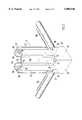
- FIG. 1is an exploded perspective partial view of a rack with a front right frame leg, to which a lateral wall and a door is attached, and
- FIG. 2is a perspective partial view in an area of a lower corner connector at a front right frame leg.
- FIG. 1Only the vertical frame legs 11 and 12 at the front right corner and the rear left corner of a rack 10 are shown in FIG. 1.
- the horizontal frame legs 13 and 14are connected by means of a corner connector 20 at the upper end of the vertical frame leg 11.
- the horizontal frame legs 15, 16, 17 and 18are shown in the lower area, of which the frame legs 15 and 18 are connected by a corner connector 20 with the lower end of the vertical frame leg 11.
- the lateral walls 40 and 44are screwed to the corner connectors 20, wherein in these areas the corners are beveled and without edges, as can be seen from the corner 43 of the lateral wall 40.
- the edge areas 41 and 45 of the lateral walls 40 and 44project into receivers 70 of the frame legs. As shown in FIG.
- the frame legsare beveled in the area of their outer edge and form a receiver 70 together with the connecting section 53 and the transition sections 54 and 55.
- the corner connector 20covers the receiver 70 with a shoulder 24.
- the shoulder 24 of the corner connector 20has a plug receiver 21.
- the surfaces 22 and 23 of the corner connector 20, which are positioned vertically with respect to each other,are flush with the exteriors of the switchgear cabinet, such as the exteriors of lateral walls 40 and 44, the rear wall 46 and the door 30 attached to the corner connector 20.
- the contact surfaces 25 and 26 for these elementsare set back by the amount of their thickness with respect to the surfaces 22 and 23 of the corner connector 20 in order to achieve a flush fit.
- the contact surfaces 25 and 26have threaded receivers 27 and 28 for screwing.
- the plug projections 65 of the corner connectors 20are inserted into receivers 62 and 63 of the frame legs and fixed therein.
- the receivers 62 and 63are delimited by multiple bent sections 56, 58, 59 or 57, 60, 61.
- the thrice bent sections 56 and 57form receiving grooves, open toward the outside, for sealing elements.
- the receiving grooves 56 and 57are located in the area of profile sides 51 and 52, which are placed vertically with respect to each other, and against which rest the lateral walls 40 and 44, the rear wall 46, the door 30 and the sheet metal bottom and cover pieces, not represented in the drawings.
- Hinge boltswhich can be adjusted and fixed in place, for example, in bearing sleeves of the door 30, are used for fastening the door 30.
- the two hinge bolts on the hinge sideare inserted into the plug receivers 21 of the two associated corner connectors 20 and fixed in place in the inserted position.
- fixation in placecan be in the bearing sleeve of the door 30 or in the plug receiver 21 of the corner connectors 20.
- the lateral walls 40 and 44, the rear wall 46 and the door 30can have beveled edge sections 41, 45, 47 or 32 and 33, that are accommodated in the receivers 70 of the frame legs 11 to 18.
- the door 30On the locking side the door 30 has a locking device 31 which can be embodied as a push rod lock, for example.
- the push rodsare used as lock bolts 35 and are adjustably inserted and held in bearing sleeves of the door 30.
- the push rod endsIn the locked state of the locking device 31, the push rod ends are introduced as lock bolts 35 into the plug receivers 21 of the adjoining corner connectors 20.
- the push rod endsWhen opening the locking device 31, the push rod ends are removed from the plug receivers 21 of the corner connectors 20, and the door 30, hinged on the hinge side, can be opened.
- the lateral walls, the rear wall, the sheet metal bottom piece and the sheet metal cover piececan be attached by fastening means not visible from the outside.
Landscapes
- Engineering & Computer Science (AREA)
- Power Engineering (AREA)
- Microelectronics & Electronic Packaging (AREA)
- Hinges (AREA)
- Patch Boards (AREA)
- Supply And Distribution Of Alternating Current (AREA)
- Control Of Electrical Variables (AREA)
- Casings For Electric Apparatus (AREA)
- Cabinets, Racks, Or The Like Of Rigid Construction (AREA)
Abstract
Description
1. Field of the Invention
This invention relates to a switchgear cabinet with a rack constructed of frame legs and corner connectors, with open sides that can be closed or are closed by lateral walls, and having a rear wall, a sheet metal bottom piece, a sheet metal cover piece and at least one door.
2. Description of Prior Art
In conventional switchgear cabinets, two profiled sides of the frame legs placed vertically with respect to each other normally form exteriors of the rack and one of the exterior edges of the rack. For hinging such door it is necessary to attach hinge elements on the vertical frame legs. In addition, on the lock side of the door it is necessary to attach locking elements for the locking device attached to the door. In this case the attachment side of the door to the rack is often fixed and cannot be changed in a simple manner at the place where the switchgear cabinet is used. Normally, an open side of the rack is closed by the door.
In connection with a switchgear cabinet of the type mentioned above, it is one object of this invention to hinge a door on a rack without special hinge and closing elements, wherein the attachment side and the closing side can be easily interchanged and wherein the door intended for one side of the rack can also be arbitrarily attached to the opposite side of the rack.
This object is attained in accordance with one preferred embodiment of this invention wherein at least the vertical frame legs are beveled in an area of outer edges and thus constitute a receiver for beveled edges of the lateral walls and the door. The corner connectors cover the receivers of the frame legs and have on a side facing the receivers plug receivers or hinge bolts. On a hinge side the door has hinge bolts or plug receivers, which can be inserted or are inserted into the plug receivers of the corner connectors, or into which the hinge bolts of the door are inserted or can be inserted. On a lock side the door has locking bolts, which can be inserted into and removed from plug receivers of the corner connectors by a closure device.
With this embodiment of the frame legs and corner connectors, the corner connectors also assume functions required for hinging and locking the door. What is needed is to provide plug receivers or hinge bolts on the corner connectors. The frame legs do not need to have hinge or locking elements. The receivers formed on the frame legs in an area of the outer edges provide sufficient space for receiving the beveled edge sections of the lateral walls and the door.
In accordance with one embodiment of this invention, the frame legs have two profiled sides placed vertically with respect to each other, which form exteriors of the rack. The profiled sides are connected with each other in an area of the outer edge by a profiled connecting section, which is placed at an angle of 135° with respect to these profiled sides. With this embodiment the frame leg can be used as the hinge or lock side of the door for both adjoining sides of the rack.
The receiver in the area of the outer edge of the frame legs can be enlarged if the profiled sides make a transition into the connecting section with profiled transition sections which are placed vertically with respect to each other.
If the corner connectors have two surfaces located vertically with respect to each other, which constitute portions of the outer edges of the rack, and the surfaces terminate flush with the exteriors of the adjoining lateral walls and the closed door, there is a flush termination in a corner area of the switchgear cabinet.
In accordance with one embodiment, screws connect the lateral walls, the rear wall, the sheet metal bottom piece and the sheet metal cover piece to the corner connectors. Fastening on the frame legs is also possible without the wall elements having fastening bores for fastening screws.
Attachment of the door on the rack is made easier by the hinge bolts or locking bolts being adjustably guided and/or maintained in bearing sleeves attached to the door.
The hinging of a door can also be performed in a simple manner with the hinge bolts, guided through bearing sleeves of the door, inserted into plug receivers of the corner connectors and held therein with a snug fit and/or a press fit.
This invention will be explained in detail by an exemplary embodiment shown in the drawings wherein:
FIG. 1 is an exploded perspective partial view of a rack with a front right frame leg, to which a lateral wall and a door is attached, and
FIG. 2 is a perspective partial view in an area of a lower corner connector at a front right frame leg.
Only thevertical frame legs rack 10 are shown in FIG. 1. Thehorizontal frame legs corner connector 20 at the upper end of thevertical frame leg 11. Thehorizontal frame legs frame legs corner connector 20 with the lower end of thevertical frame leg 11. Thelateral walls 40 and 44 are screwed to thecorner connectors 20, wherein in these areas the corners are beveled and without edges, as can be seen from thecorner 43 of thelateral wall 40. Theedge areas lateral walls 40 and 44 project intoreceivers 70 of the frame legs. As shown in FIG. 2, the frame legs are beveled in the area of their outer edge and form areceiver 70 together with the connectingsection 53 and thetransition sections corner connector 20 covers thereceiver 70 with ashoulder 24. Theshoulder 24 of thecorner connector 20 has aplug receiver 21. Thesurfaces corner connector 20, which are positioned vertically with respect to each other, are flush with the exteriors of the switchgear cabinet, such as the exteriors oflateral walls 40 and 44, therear wall 46 and thedoor 30 attached to thecorner connector 20. Thecontact surfaces surfaces corner connector 20 in order to achieve a flush fit. Thecontact surfaces receivers
Theplug projections 65 of thecorner connectors 20 are inserted into receivers 62 and 63 of the frame legs and fixed therein. The receivers 62 and 63 are delimited bymultiple bent sections thrice bent sections receiving grooves profile sides lateral walls 40 and 44, therear wall 46, thedoor 30 and the sheet metal bottom and cover pieces, not represented in the drawings.
Hinge bolts, which can be adjusted and fixed in place, for example, in bearing sleeves of thedoor 30, are used for fastening thedoor 30. For fastening thedoor 30, the two hinge bolts on the hinge side are inserted into theplug receivers 21 of the two associatedcorner connectors 20 and fixed in place in the inserted position.
In this case fixation in place can be in the bearing sleeve of thedoor 30 or in theplug receiver 21 of thecorner connectors 20.
Thelateral walls 40 and 44, therear wall 46 and thedoor 30 can have bevelededge sections receivers 70 of theframe legs 11 to 18.
On the locking side thedoor 30 has alocking device 31 which can be embodied as a push rod lock, for example. The push rods are used aslock bolts 35 and are adjustably inserted and held in bearing sleeves of thedoor 30. In the locked state of thelocking device 31, the push rod ends are introduced aslock bolts 35 into theplug receivers 21 of theadjoining corner connectors 20. When opening thelocking device 31, the push rod ends are removed from theplug receivers 21 of thecorner connectors 20, and thedoor 30, hinged on the hinge side, can be opened.
The lateral walls, the rear wall, the sheet metal bottom piece and the sheet metal cover piece can be attached by fastening means not visible from the outside.
Claims (13)
1. In a switchgear cabinet having a rack frame with a plurality of horizontal and vertical frame legs assembled together by a plurality of corner connectors forming a frame with a plurality of open sides selectively closed by lateral walls, a rear wall, and at least one door, the improvement comprising:
vertical frame legs (11) of the frame legs having a plurality of outer edges beveled forming a plurality of recessed receivers (70) in said frame selectively receiving a plurality of beveled edges (34, 41, 45) of the lateral walls (40, 44) and the door (30),
the corner connectors (20) connected to ends of the horizontal and vertical frame legs, said corner connectors having a shoulder (24) forming end walls of the receivers (70), said end walls having on sides facing into the receivers (70) a plurality of plug receivers (21) forming vertically aligned pairs at opposite ends of the vertical frame legs,
a lock side of the door (30) having a plurality of locking bolts (35), which are selectively inserted into the plug receivers (21) of the corner connectors (20) by a closure device (31),
said plug receivers alternatively receiving hinge bolts of an opposite hinge side of the door whereby the direction of swing for the door may be selected.
2. In the switchgear cabinet in accordance with claim 1, wherein
the frame legs (11) have two profiled sides (51, 52) placed perpendicular with respect to each other which form exteriors of the rack frame (10), and
the profiled sides (51, 52) connected with each other near the outer edges by the recessed receiver (70) comprising a profiled connecting section (53) which is placed at an angle of 135° with respect to the profiled sides (51, 52).
3. In the switchgear cabinet in accordance with claim 2, wherein
the recessed receiver (70) comprises a connecting section (53) and a plurality of profiled transition sections (54, 55) which are placed perpendicular with respect to corresponding ones of the profiled sides (51, 52).
4. In the switchgear cabinet in accordance with claim 3, wherein
the corner connectors (20) have two surfaces (22, 23) positioned perpendicular with respect to each other forming the outer edges of the rack frame (10), and
the surfaces (22, 23) terminate flush with exterior surfaces of the lateral walls (40, 44) and the closed door (30).
5. In the switchgear cabinet in accordance with claim 4, wherein
the lateral walls (40, 44) and the rear wall (46) are screwed together with the corner connectors (20), wherein the corner connectors (20) have a plurality of contact surfaces (25, 26) set back by a thickness of the lateral walls (40, 44).
6. In the switchgear cabinet in accordance with claim 5, wherein
the hinge bolts are attached with respect to the door (30).
7. In the switchgear cabinet in accordance with claim 6, wherein
the hinge bolts are inserted into the plug receivers (21) of the corner connectors (20) and secured with a press fit.
8. In the switchgear cabinet in accordance with claim 7, wherein
the lateral walls (40, 44) and the rear wall (46) are fastened on the frame legs.
9. In a switchgear cabinet having a rack frame with a plurality of frame legs connected together by a plurality of corner connectors, said rack frame forming a plurality of open sides which can be closed by lateral walls, a rear wall, and at least one door, the improvement comprising:
at least two vertical frame legs (11) of the frame legs having a plurality of outer edges beveled forming a plurality of recessed receivers (70) receiving a plurality of beveled edges (34, 41, 45) of the lateral walls (40, 44) and the door (30),
the corner connectors (20) connected to and covering ends of the receivers (70) of the vertical frame legs (11) and having on a side facing into the receivers (70) a plurality of plug receivers (21),
a lock side of the door (30) having a plurality of locking bolts (35), which are selectively inserted into the plug receivers (21) of the corner connectors (20) by a closure device (31),
said plug receivers alternatively receiving hinge bolts of an opposite hinge side of the door whereby the direction of swing for the door may be selected,
the corner connectors (20) having two surfaces (22, 23) positioned perpendicular with respect to each other forming the outer edges of the rack (10), and
the surfaces (22, 23) terminating flush with exterior surfaces of the lateral walls (40, 44) and the closed door (30).
10. In the switchgear cabinet in accordance with claim 1, wherein
the lateral walls (40, 44) and the rear wall (46) are screwed together with the corner connectors (20), wherein the corner connectors (20) have a plurality of contact surfaces (25, 26) set back by a thickness of the lateral walls (40, 44).
11. In the switchgear cabinet in accordance with claim 1, wherein
the hinge bolts are attached to the door (30).
12. In a switchgear cabinet having a rack frame with a plurality of frame legs connected together by a plurality of corner connectors, said rack frame forming a plurality of open sides which can be closed by lateral walls, a rear wall, and at least one door, the improvement comprising:
at least two vertical frame legs (11) of the frame legs having a plurality of outer edges beveled forming a plurality of recessed receivers (70) receiving a plurality of beveled edges (34, 41, 45) of the lateral walls (40, 44) and the door (30),
the corner connectors (20) connected to and covering ends of the receivers (70) of the vertical frame legs (11) and having on a side facing into the receivers (70) a plurality of plug receivers (21),
a lock side of the door (30) having a plurality of locking bolts (35), which are selectively inserted into the plug receivers (21) of the corner connectors (20) by a closure device (31),
said plug receivers alternatively receiving hinge bolts of an opposite hinge side of the door whereby the direction of swing for the door may be selected,
the hinge bolts attached with respect to the door (30) being inserted into the plug receivers (21) of the corner connectors (20) and secured with a press fit.
13. In a switchgear cabinet having a rack frame with a plurality of frame legs connected together by a plurality of corner connectors, said rack frame forming a plurality of open sides which can be closed by lateral walls, a rear wall, and at least one door, the improvement comprising:
at least two vertical frame legs (11) of the frame legs having a plurality of outer edges beveled forming a plurality of recessed receivers (70) receiving a plurality of beveled edges (34, 41, 45) of the lateral walls (40, 44) and the door (30),
the corner connectors (20) connected to and covering ends of the receivers (70) of the vertical frame legs (11) and having on a side facing into the receivers (70) a plurality of plug receivers (21),
a lock side of the door (30) having a plurality of locking bolts (35), which are selectively inserted into the plug receivers (21) of the corner connectors (20) by a closure device (31),
said plug receivers alternatively receiving hinge bolts of an opposite hinge side of the door whereby the direction of swing for the door may be selected,
the lateral walls (40, 44) and the rear wall (46) being fastened on the frame legs.
Applications Claiming Priority (3)
| Application Number | Priority Date | Filing Date | Title |
|---|---|---|---|
| DE4439607.4 | 1994-11-05 | ||
| DE4439607ADE4439607C1 (en) | 1994-11-05 | 1994-11-05 | Switching cabinet frame construction |
| PCT/EP1995/004287WO1996014729A1 (en) | 1994-11-05 | 1995-11-02 | Switchgear cabinet with frame |
Publications (1)
| Publication Number | Publication Date |
|---|---|
| US5806946Atrue US5806946A (en) | 1998-09-15 |
Family
ID=6532606
Family Applications (1)
| Application Number | Title | Priority Date | Filing Date |
|---|---|---|---|
| US08/836,239Expired - Fee RelatedUS5806946A (en) | 1994-11-05 | 1995-11-02 | Switchgear cabinet with frame |
Country Status (8)
| Country | Link |
|---|---|
| US (1) | US5806946A (en) |
| EP (1) | EP0789985B1 (en) |
| JP (1) | JPH10508516A (en) |
| AU (1) | AU689980B2 (en) |
| BR (1) | BR9509558A (en) |
| DE (1) | DE4439607C1 (en) |
| ES (1) | ES2122697T3 (en) |
| WO (1) | WO1996014729A1 (en) |
Cited By (44)
| Publication number | Priority date | Publication date | Assignee | Title |
|---|---|---|---|---|
| US5992646A (en)* | 1995-10-04 | 1999-11-30 | Rittal-Werk Rudolf Loh Gmbh & Co. Kg | Framework for switchgear cabinets |
| USD429485S (en)* | 1997-09-25 | 2000-08-15 | Rittal-Werk Rudolf Loh Gmbh & Co. Kg | Cover for the closure of a switchgear cabinet |
| US6138843A (en)* | 1998-04-17 | 2000-10-31 | Rittal-Werk Rudolf Loh Gmbh & Co. Kg | Frame piece for a rack of a switching cabinet |
| US6164460A (en)* | 1998-03-26 | 2000-12-26 | Rittal-Werk Rudolf Loh Gmbh & Co. Kg | Rack for a switchgear cabinet |
| US6206211B1 (en)* | 1998-04-20 | 2001-03-27 | Rittal-Werk Rudolf Loh Gmbh & Co. Kg | Frame piece for a rack of a switching cabinet |
| US6211466B1 (en)* | 1996-11-19 | 2001-04-03 | Rittal-Werk Rudolf Loh Gmbh & Co. Kg | Switching cabinet |
| US6293637B1 (en) | 2000-05-12 | 2001-09-25 | Amco Engineering Co. | Earthquake-resistant electronic equipment frame |
| US20020050772A1 (en)* | 2000-10-27 | 2002-05-02 | Josef Knab | Cabinet, particularly equipment cabinet |
| US6428127B1 (en)* | 1998-04-27 | 2002-08-06 | Knud Rasmussen | Cabinet frame |
| GB2374520A (en)* | 2001-03-21 | 2002-10-23 | Rittal Rcs Comm Systems Gmbh & Co Kg | Corner construction of a switchgear cabinet |
| GB2374793A (en)* | 2001-03-21 | 2002-10-30 | Rittal Rcs Comm Systems Gmbh & Co Kg | Corner construction of a switchgear cabinet |
| US6481582B1 (en) | 2001-06-04 | 2002-11-19 | Cooper Technologies Company | Rack |
| US20030048048A1 (en)* | 2001-07-27 | 2003-03-13 | Heine Altena | Switch cabinet frame structure |
| US6605777B1 (en)* | 2002-07-29 | 2003-08-12 | Amco Engineering Co. | Earthquake-resistant electronic equipment frame |
| US20040183409A1 (en)* | 2001-01-23 | 2004-09-23 | Cooper Technologies Company | Electrical equipment enclosure |
| US7129409B1 (en)* | 2004-05-07 | 2006-10-31 | Lester Brian Hicks | Electronics cabinet |
| USD543161S1 (en)* | 2006-03-27 | 2007-05-22 | Knuerr Ag | Cabinet |
| US20070247041A1 (en)* | 2003-05-30 | 2007-10-25 | Andrew Hudz | Global rack system |
| US20080035810A1 (en)* | 2006-08-12 | 2008-02-14 | Chatsworth Products, Inc. | Offset brackets for expanding electronic equipment cabinets |
| US20080316702A1 (en)* | 2007-05-17 | 2008-12-25 | Chatsworth Products, Inc. | Exhaust air duct with adjustable filler panel assemblies |
| US7772489B2 (en) | 2006-03-13 | 2010-08-10 | Panduit Corp. | Network cabinet |
| USD630173S1 (en) | 2009-04-20 | 2011-01-04 | Chatsworth Products, Inc. | Cover for electronic equipment cabinet |
| USD632660S1 (en) | 2009-04-20 | 2011-02-15 | Chatsworth Products, Inc. | Cover for electronic equipment cabinet |
| US20110050052A1 (en)* | 2009-09-01 | 2011-03-03 | Emerson Network Power, Energy Systems, North America, Inc. | Telecommunications Enclosures |
| US20110181160A1 (en)* | 2010-01-25 | 2011-07-28 | Hong Fu Jin Precision Industry (Shenzhen) Co., Ltd. | Switching cabinet and assembly method of the same |
| US8016126B1 (en) | 2003-09-30 | 2011-09-13 | Google Inc. | Cabinet structures resistant to racking deformation for rack mounted computing systems |
| US20120055924A1 (en)* | 2010-09-08 | 2012-03-08 | Abb Ag | Electrical switchgear cabinet |
| US20120146471A1 (en)* | 2009-08-24 | 2012-06-14 | Gabriele Centazzo | Modular Piece Of Furniture Made Of Recyclable Materials |
| USD684128S1 (en) | 2012-02-10 | 2013-06-11 | Chatsworth Products, Inc. | Containment aisle door |
| US8653363B2 (en) | 2010-06-01 | 2014-02-18 | Chatsworth Products, Inc. | Magnetic filler panel for use in airflow control system in electronic equipment enclosure |
| US8787023B2 (en) | 2010-09-10 | 2014-07-22 | Chatsworth Products, Inc. | Rail mounting clamp for electronic equipment enclosure |
| US8901438B2 (en) | 2010-09-10 | 2014-12-02 | Chatsworth Products, Inc. | Electronic equipment cabinet structure |
| US20140367923A1 (en)* | 2011-02-25 | 2014-12-18 | C E S Control Enclosure Systems Gmbh | Sealing element and a sealing system for hollow sections |
| US20140374369A1 (en)* | 2013-06-24 | 2014-12-25 | Abb S.P.A. | Frame assembly for a switchboard and related frame and switchboard |
| US9055677B2 (en) | 2010-09-10 | 2015-06-09 | Chatsworth Products, Inc. | Cable pass-through panel for electronic equipment enclosure |
| US9549482B2 (en) | 2014-09-05 | 2017-01-17 | Emerson Network Power, Energy Systems, North America, Inc. | Cabinet frame enclosures, frame members and corresponding methods |
| US9655259B2 (en) | 2011-12-09 | 2017-05-16 | Chatsworth Products, Inc. | Data processing equipment structure |
| US10045460B2 (en)* | 2014-09-02 | 2018-08-07 | Cp Cases Limited | Electronic rack and mounting chassis |
| US10045620B2 (en) | 2013-11-25 | 2018-08-14 | Erich Oehler | Reconfigurable furniture system |
| WO2019218039A1 (en)* | 2018-05-17 | 2019-11-21 | Melquisedec Francisquini | Structural column and modular structure for electrical cabinets comprising said structural column |
| US10694845B2 (en)* | 2016-07-08 | 2020-06-30 | Mill Brothers Landscape & Nursery, Inc. | Grill insert enclosure |
| US11464336B2 (en)* | 2018-10-12 | 2022-10-11 | Samsung Electronics Co., Ltd. | Panel assembly and home appliance having the same |
| US11564489B2 (en)* | 2018-06-19 | 2023-01-31 | SieMatic Möbelwerke GmbH & Co. KG | Furniture system |
| US20230165366A1 (en)* | 2019-06-07 | 2023-06-01 | Corning Research & Development Corporation | Sealing corner bracket for receiving two frame members and cabinet including corner bracket |
Families Citing this family (4)
| Publication number | Priority date | Publication date | Assignee | Title |
|---|---|---|---|---|
| DE19600653C2 (en)* | 1996-01-10 | 2000-09-28 | May & Steffens Gmbh & Co Kg | Meter and distribution cabinet |
| JP5559135B2 (en)* | 2011-12-22 | 2014-07-23 | タキゲン製造株式会社 | Equipment storage rack |
| CN103002704B (en)* | 2012-11-16 | 2015-07-08 | 无锡康贝电子设备有限公司 | Column section for machine cabinet frame |
| CN102984913B (en)* | 2012-11-16 | 2015-07-08 | 无锡康贝电子设备有限公司 | Cabinet structure |
Citations (16)
| Publication number | Priority date | Publication date | Assignee | Title |
|---|---|---|---|---|
| GB1336991A (en)* | 1969-12-22 | 1973-11-14 | Symons M W | Structure and method of forming such a structure |
| DE2437645A1 (en)* | 1974-08-05 | 1976-02-26 | Siemens Ag | Frame for communication and measurement equipment - unit or stack is elastically supported by rubber pads at corners |
| US4229921A (en)* | 1978-11-30 | 1980-10-28 | The Maytag Company | Appliance door decorator panel construction |
| DE8107658U1 (en)* | 1981-03-17 | 1981-08-20 | Hans Knürr KG Mechanik für die Elektronik, 8000 München | Housings, in particular for electrical and / or electronic circuits |
| US4671015A (en)* | 1986-04-07 | 1987-06-09 | Curry David G | Rapid dismount security door |
| EP0389910A1 (en)* | 1989-03-28 | 1990-10-03 | Siemens Nixdorf Informationssysteme Aktiengesellschaft | Modular cabinet system for electronic assemblies |
| US4966424A (en)* | 1988-05-05 | 1990-10-30 | W. Schneider & Co., Ag Metallwarenfabrik | Cabinet construction |
| DE4036664A1 (en)* | 1990-11-17 | 1992-05-21 | Loh Kg Rittal Werk | Frame of profiled section material suitable for forming circuitry cabinet - is of double wall shape to provide high stiffness |
| US5165770A (en)* | 1991-03-29 | 1992-11-24 | Richard Hahn | Electronic equipment modular cabinet system |
| DE4132803A1 (en)* | 1991-10-02 | 1993-04-08 | Loh Kg Rittal Werk | Hollow profile for switch cabinet frame - has two perpendicular side faces each with lipped flange joined together by angled coupling section |
| US5222871A (en)* | 1989-03-09 | 1993-06-29 | Durr Dental Gmbh & Co Kg | Compressed air and underpressure supply unit |
| US5228762A (en)* | 1990-05-18 | 1993-07-20 | Transrack | Metal cabinet frame |
| US5275296A (en)* | 1991-12-12 | 1994-01-04 | Rittal-Werk Rudolf Loh Gmbh & Co. Kg | Rack for a control cabinet |
| FR2697300A1 (en)* | 1992-10-22 | 1994-04-29 | Legrand Sa | Device for assembling framework construction of electricity cabinet - attaches rectangular framework to vertical support with snap fit attachment sliding into place on main arm section |
| US5407263A (en)* | 1991-11-27 | 1995-04-18 | Federal-Hoffman, Inc. | Restructurable enclosure with multi-purpose mounting blocks |
| US5498073A (en)* | 1993-10-18 | 1996-03-12 | Schneider Electric Sa | Corner junction for cabinet, and electrical cabinet comprising such junctions |
Family Cites Families (1)
| Publication number | Priority date | Publication date | Assignee | Title |
|---|---|---|---|---|
| JPH0823779B2 (en)* | 1988-01-22 | 1996-03-06 | 東北電機製造株式会社 | Power control device |
- 1994
- 1994-11-05DEDE4439607Apatent/DE4439607C1/ennot_activeExpired - Fee Related
- 1995
- 1995-11-02BRBR9509558Apatent/BR9509558A/ennot_activeApplication Discontinuation
- 1995-11-02ESES95938386Tpatent/ES2122697T3/ennot_activeExpired - Lifetime
- 1995-11-02JPJP8515034Apatent/JPH10508516A/enactivePending
- 1995-11-02AUAU39798/95Apatent/AU689980B2/ennot_activeCeased
- 1995-11-02WOPCT/EP1995/004287patent/WO1996014729A1/enactiveIP Right Grant
- 1995-11-02EPEP95938386Apatent/EP0789985B1/ennot_activeExpired - Lifetime
- 1995-11-02USUS08/836,239patent/US5806946A/ennot_activeExpired - Fee Related
Patent Citations (16)
| Publication number | Priority date | Publication date | Assignee | Title |
|---|---|---|---|---|
| GB1336991A (en)* | 1969-12-22 | 1973-11-14 | Symons M W | Structure and method of forming such a structure |
| DE2437645A1 (en)* | 1974-08-05 | 1976-02-26 | Siemens Ag | Frame for communication and measurement equipment - unit or stack is elastically supported by rubber pads at corners |
| US4229921A (en)* | 1978-11-30 | 1980-10-28 | The Maytag Company | Appliance door decorator panel construction |
| DE8107658U1 (en)* | 1981-03-17 | 1981-08-20 | Hans Knürr KG Mechanik für die Elektronik, 8000 München | Housings, in particular for electrical and / or electronic circuits |
| US4671015A (en)* | 1986-04-07 | 1987-06-09 | Curry David G | Rapid dismount security door |
| US4966424A (en)* | 1988-05-05 | 1990-10-30 | W. Schneider & Co., Ag Metallwarenfabrik | Cabinet construction |
| US5222871A (en)* | 1989-03-09 | 1993-06-29 | Durr Dental Gmbh & Co Kg | Compressed air and underpressure supply unit |
| EP0389910A1 (en)* | 1989-03-28 | 1990-10-03 | Siemens Nixdorf Informationssysteme Aktiengesellschaft | Modular cabinet system for electronic assemblies |
| US5228762A (en)* | 1990-05-18 | 1993-07-20 | Transrack | Metal cabinet frame |
| DE4036664A1 (en)* | 1990-11-17 | 1992-05-21 | Loh Kg Rittal Werk | Frame of profiled section material suitable for forming circuitry cabinet - is of double wall shape to provide high stiffness |
| US5165770A (en)* | 1991-03-29 | 1992-11-24 | Richard Hahn | Electronic equipment modular cabinet system |
| DE4132803A1 (en)* | 1991-10-02 | 1993-04-08 | Loh Kg Rittal Werk | Hollow profile for switch cabinet frame - has two perpendicular side faces each with lipped flange joined together by angled coupling section |
| US5407263A (en)* | 1991-11-27 | 1995-04-18 | Federal-Hoffman, Inc. | Restructurable enclosure with multi-purpose mounting blocks |
| US5275296A (en)* | 1991-12-12 | 1994-01-04 | Rittal-Werk Rudolf Loh Gmbh & Co. Kg | Rack for a control cabinet |
| FR2697300A1 (en)* | 1992-10-22 | 1994-04-29 | Legrand Sa | Device for assembling framework construction of electricity cabinet - attaches rectangular framework to vertical support with snap fit attachment sliding into place on main arm section |
| US5498073A (en)* | 1993-10-18 | 1996-03-12 | Schneider Electric Sa | Corner junction for cabinet, and electrical cabinet comprising such junctions |
Cited By (90)
| Publication number | Priority date | Publication date | Assignee | Title |
|---|---|---|---|---|
| US5992646A (en)* | 1995-10-04 | 1999-11-30 | Rittal-Werk Rudolf Loh Gmbh & Co. Kg | Framework for switchgear cabinets |
| US6211466B1 (en)* | 1996-11-19 | 2001-04-03 | Rittal-Werk Rudolf Loh Gmbh & Co. Kg | Switching cabinet |
| USD429485S (en)* | 1997-09-25 | 2000-08-15 | Rittal-Werk Rudolf Loh Gmbh & Co. Kg | Cover for the closure of a switchgear cabinet |
| US6164460A (en)* | 1998-03-26 | 2000-12-26 | Rittal-Werk Rudolf Loh Gmbh & Co. Kg | Rack for a switchgear cabinet |
| US6138843A (en)* | 1998-04-17 | 2000-10-31 | Rittal-Werk Rudolf Loh Gmbh & Co. Kg | Frame piece for a rack of a switching cabinet |
| US6206211B1 (en)* | 1998-04-20 | 2001-03-27 | Rittal-Werk Rudolf Loh Gmbh & Co. Kg | Frame piece for a rack of a switching cabinet |
| US6428127B1 (en)* | 1998-04-27 | 2002-08-06 | Knud Rasmussen | Cabinet frame |
| US6293637B1 (en) | 2000-05-12 | 2001-09-25 | Amco Engineering Co. | Earthquake-resistant electronic equipment frame |
| US6712434B2 (en)* | 2000-10-27 | 2004-03-30 | Knuerr Ag | Cabinet, particularly equipment cabinet |
| US20020050772A1 (en)* | 2000-10-27 | 2002-05-02 | Josef Knab | Cabinet, particularly equipment cabinet |
| EP1202416A3 (en)* | 2000-10-27 | 2002-09-18 | Knürr AG | Cabinet, in particular installation cabinet |
| US20040183409A1 (en)* | 2001-01-23 | 2004-09-23 | Cooper Technologies Company | Electrical equipment enclosure |
| GB2374793B (en)* | 2001-03-21 | 2004-07-28 | Rittal Rcs Comm Systems Gmbh & Co Kg | Switchgear cabinet including framework and covering members |
| GB2374520B (en)* | 2001-03-21 | 2004-04-07 | Rittal Rcs Comm Systems Gmbh & Co Kg | Switchgear cabinet including framework and covering members |
| GB2374520A (en)* | 2001-03-21 | 2002-10-23 | Rittal Rcs Comm Systems Gmbh & Co Kg | Corner construction of a switchgear cabinet |
| US6640980B2 (en)* | 2001-03-21 | 2003-11-04 | Rittal Rcs Communication | Switchgear cabinet including framework and covering members |
| GB2374793A (en)* | 2001-03-21 | 2002-10-30 | Rittal Rcs Comm Systems Gmbh & Co Kg | Corner construction of a switchgear cabinet |
| US6481582B1 (en) | 2001-06-04 | 2002-11-19 | Cooper Technologies Company | Rack |
| US20030048048A1 (en)* | 2001-07-27 | 2003-03-13 | Heine Altena | Switch cabinet frame structure |
| US6808240B2 (en)* | 2001-07-27 | 2004-10-26 | Ise Innomotive Systems Europe Gmbh | Switch cabinet frame structure |
| US6605777B1 (en)* | 2002-07-29 | 2003-08-12 | Amco Engineering Co. | Earthquake-resistant electronic equipment frame |
| US7478890B2 (en) | 2003-05-30 | 2009-01-20 | Sanmina-Sci Corporation | Global rack system |
| US8083301B2 (en) | 2003-05-30 | 2011-12-27 | Sanmina-Sci Corporation | Global rack system |
| US20070247041A1 (en)* | 2003-05-30 | 2007-10-25 | Andrew Hudz | Global rack system |
| US20090236957A1 (en)* | 2003-05-30 | 2009-09-24 | Sanmina-Sci Corporation | Global rack system |
| US8016126B1 (en) | 2003-09-30 | 2011-09-13 | Google Inc. | Cabinet structures resistant to racking deformation for rack mounted computing systems |
| US7129409B1 (en)* | 2004-05-07 | 2006-10-31 | Lester Brian Hicks | Electronics cabinet |
| WO2007064513A3 (en)* | 2005-11-30 | 2007-11-29 | Sanmina Sci Corp | Global rack system |
| US8237052B2 (en) | 2006-03-13 | 2012-08-07 | Panduit Corp. | Network cabinet |
| US7880084B2 (en) | 2006-03-13 | 2011-02-01 | Panduit Corp. | Network cabinet |
| US20110084580A1 (en)* | 2006-03-13 | 2011-04-14 | Panduit Corp. | Network Cabinet |
| US8802978B2 (en) | 2006-03-13 | 2014-08-12 | Panduit Corp. | Network cabinet |
| US20100264788A1 (en)* | 2006-03-13 | 2010-10-21 | Panduit Corp. | Network cabinet |
| US7772489B2 (en) | 2006-03-13 | 2010-08-10 | Panduit Corp. | Network cabinet |
| USD543161S1 (en)* | 2006-03-27 | 2007-05-22 | Knuerr Ag | Cabinet |
| US20080035810A1 (en)* | 2006-08-12 | 2008-02-14 | Chatsworth Products, Inc. | Offset brackets for expanding electronic equipment cabinets |
| US20080316703A1 (en)* | 2007-05-17 | 2008-12-25 | Chatsworth Products, Inc. | Electronic equipment enclosure with exhaust air duct and adjustable filler panel assemblies |
| US20090129013A1 (en)* | 2007-05-17 | 2009-05-21 | Chatsworth Products, Inc. | Electronic equipment enclosure with exhaust air duct and adjustable filler panel assemblies |
| US7697285B2 (en) | 2007-05-17 | 2010-04-13 | Chatsworth Products, Inc. | Electronic equipment enclosure with exhaust air duct and adjustable filler panel assemblies |
| US7746637B2 (en) | 2007-05-17 | 2010-06-29 | Chatsworth Products, Inc. | Electronic equipment enclosure with exhaust air duct and adjustable filler panel assemblies |
| US20110148261A1 (en)* | 2007-05-17 | 2011-06-23 | Donowho D Brian | Exhaust air duct with adjustable filler panel assemblies |
| US20080316702A1 (en)* | 2007-05-17 | 2008-12-25 | Chatsworth Products, Inc. | Exhaust air duct with adjustable filler panel assemblies |
| US7839635B2 (en) | 2007-05-17 | 2010-11-23 | Chatsworth Products, Inc. | Exhaust air duct with adjustable filler panel assemblies |
| US8405984B2 (en) | 2007-05-17 | 2013-03-26 | Chatsworth Products, Inc. | Exhaust air duct with adjustable filler panel assemblies |
| USD632660S1 (en) | 2009-04-20 | 2011-02-15 | Chatsworth Products, Inc. | Cover for electronic equipment cabinet |
| USD630173S1 (en) | 2009-04-20 | 2011-01-04 | Chatsworth Products, Inc. | Cover for electronic equipment cabinet |
| US8579388B2 (en)* | 2009-08-24 | 2013-11-12 | Valcucine S.P.A. | Modular piece of furniture made of recyclable materials |
| US20120146471A1 (en)* | 2009-08-24 | 2012-06-14 | Gabriele Centazzo | Modular Piece Of Furniture Made Of Recyclable Materials |
| US20110050052A1 (en)* | 2009-09-01 | 2011-03-03 | Emerson Network Power, Energy Systems, North America, Inc. | Telecommunications Enclosures |
| US8403431B2 (en)* | 2009-09-01 | 2013-03-26 | Emerson Network Power, Energy Systems, North America, Inc. | Telecommunications enclosures |
| US20110181160A1 (en)* | 2010-01-25 | 2011-07-28 | Hong Fu Jin Precision Industry (Shenzhen) Co., Ltd. | Switching cabinet and assembly method of the same |
| US8653363B2 (en) | 2010-06-01 | 2014-02-18 | Chatsworth Products, Inc. | Magnetic filler panel for use in airflow control system in electronic equipment enclosure |
| US20120055924A1 (en)* | 2010-09-08 | 2012-03-08 | Abb Ag | Electrical switchgear cabinet |
| US8926030B2 (en)* | 2010-09-08 | 2015-01-06 | Abb Ag | Electrical switchgear cabinet |
| US9055677B2 (en) | 2010-09-10 | 2015-06-09 | Chatsworth Products, Inc. | Cable pass-through panel for electronic equipment enclosure |
| US9408326B2 (en) | 2010-09-10 | 2016-08-02 | Chatsworth Products, Inc. | Electronic equipment cabinet structure |
| US12108553B2 (en) | 2010-09-10 | 2024-10-01 | Chatsworth Products, Inc. | Cable pass-through panel for electronic equipment enclosure |
| US11792948B2 (en) | 2010-09-10 | 2023-10-17 | Chatsworth Products, Inc. | Cable pass-through panel for electronic equipment enclosure |
| US8787023B2 (en) | 2010-09-10 | 2014-07-22 | Chatsworth Products, Inc. | Rail mounting clamp for electronic equipment enclosure |
| US9814159B2 (en) | 2010-09-10 | 2017-11-07 | Chatsworth Products, Inc. | Rail seal for electronic equipment enclosure |
| US11464123B2 (en) | 2010-09-10 | 2022-10-04 | Chatsworth Products, Inc. | Method of adapting an electronic equipment enclosure for cable management |
| US8901438B2 (en) | 2010-09-10 | 2014-12-02 | Chatsworth Products, Inc. | Electronic equipment cabinet structure |
| US11039543B2 (en) | 2010-09-10 | 2021-06-15 | Chatsworth Products, Inc. | Vertical mounting rail with cable management features |
| US10653025B2 (en) | 2010-09-10 | 2020-05-12 | Chatsworth Products, Inc. | Cable pass-through panel for electronic equipment enclosure |
| US10588227B2 (en) | 2010-09-10 | 2020-03-10 | Chatsworth Products, Inc. | Vertical mounting rail with cable management features |
| US10237994B2 (en) | 2010-09-10 | 2019-03-19 | Chatsworth Products, Inc. | Vertical mounting rail with cable management features |
| US10178784B2 (en) | 2010-09-10 | 2019-01-08 | Chatsworth Products, Inc. | Rail seal for electronic equipment enclosure |
| US9642270B2 (en) | 2010-09-10 | 2017-05-02 | Chatsworth Products, Inc. | Rail seal for electronic equipment enclosure |
| US9980400B2 (en) | 2010-09-10 | 2018-05-22 | Chatsworth Products, Inc. | Rail seal for electronic equipment enclosure |
| US9781852B2 (en) | 2010-09-10 | 2017-10-03 | Chatsworth Products, Inc. | Cable pass-through panel for electronic equipment enclosure |
| US20140367923A1 (en)* | 2011-02-25 | 2014-12-18 | C E S Control Enclosure Systems Gmbh | Sealing element and a sealing system for hollow sections |
| US9383016B2 (en)* | 2011-02-25 | 2016-07-05 | C E S Control Enclosure Systems Gmbh | Sealing element and a sealing system for hollow sections |
| US10709039B2 (en) | 2011-12-09 | 2020-07-07 | Chatsworth Products, Inc. | Data processing equipment structure |
| US9655259B2 (en) | 2011-12-09 | 2017-05-16 | Chatsworth Products, Inc. | Data processing equipment structure |
| USD684128S1 (en) | 2012-02-10 | 2013-06-11 | Chatsworth Products, Inc. | Containment aisle door |
| US9627860B2 (en)* | 2013-06-24 | 2017-04-18 | Abb S.P.A. | Frame assembly for a switchboard and related frame and switchboard |
| US20140374369A1 (en)* | 2013-06-24 | 2014-12-25 | Abb S.P.A. | Frame assembly for a switchboard and related frame and switchboard |
| US10045620B2 (en) | 2013-11-25 | 2018-08-14 | Erich Oehler | Reconfigurable furniture system |
| US10045460B2 (en)* | 2014-09-02 | 2018-08-07 | Cp Cases Limited | Electronic rack and mounting chassis |
| US9622369B2 (en) | 2014-09-05 | 2017-04-11 | Emerson Network Power, Energy Systems, North America, Inc. | Cabinet frame enclosures, frame members and corresponding methods |
| US9549482B2 (en) | 2014-09-05 | 2017-01-17 | Emerson Network Power, Energy Systems, North America, Inc. | Cabinet frame enclosures, frame members and corresponding methods |
| US9578772B2 (en) | 2014-09-05 | 2017-02-21 | Emerson Network Power, Energy Systems, North America, Inc. | Cabinet frame enclosures, frame members and corresponding methods |
| US9596778B2 (en) | 2014-09-05 | 2017-03-14 | Emerson Network Power, Energy Systems, North America, Inc. | Cabinet frame enclosures, frame members and corresponding methods |
| US10694845B2 (en)* | 2016-07-08 | 2020-06-30 | Mill Brothers Landscape & Nursery, Inc. | Grill insert enclosure |
| US11432646B2 (en) | 2018-05-17 | 2022-09-06 | Melquisedec Francisquini | Structural column and modular structure for electrical cabinets including referred structural column |
| WO2019218039A1 (en)* | 2018-05-17 | 2019-11-21 | Melquisedec Francisquini | Structural column and modular structure for electrical cabinets comprising said structural column |
| US11564489B2 (en)* | 2018-06-19 | 2023-01-31 | SieMatic Möbelwerke GmbH & Co. KG | Furniture system |
| US11464336B2 (en)* | 2018-10-12 | 2022-10-11 | Samsung Electronics Co., Ltd. | Panel assembly and home appliance having the same |
| US20230165366A1 (en)* | 2019-06-07 | 2023-06-01 | Corning Research & Development Corporation | Sealing corner bracket for receiving two frame members and cabinet including corner bracket |
| US11871843B2 (en)* | 2019-06-07 | 2024-01-16 | Corning Research & Development Corporation | Sealing corner bracket for receiving two frame members and cabinet including corner bracket |
Also Published As
| Publication number | Publication date |
|---|---|
| ES2122697T3 (en) | 1998-12-16 |
| EP0789985B1 (en) | 1998-08-12 |
| AU689980B2 (en) | 1998-04-09 |
| WO1996014729A1 (en) | 1996-05-17 |
| EP0789985A1 (en) | 1997-08-20 |
| JPH10508516A (en) | 1998-08-25 |
| AU3979895A (en) | 1996-05-31 |
| BR9509558A (en) | 1997-09-16 |
| DE4439607C1 (en) | 1995-12-14 |
Similar Documents
| Publication | Publication Date | Title |
|---|---|---|
| US5806946A (en) | Switchgear cabinet with frame | |
| US6712434B2 (en) | Cabinet, particularly equipment cabinet | |
| US6238027B1 (en) | Switching cabinet | |
| US6039420A (en) | Frame for a switchgear cabinet | |
| US5498073A (en) | Corner junction for cabinet, and electrical cabinet comprising such junctions | |
| US5695263A (en) | Cabinet | |
| US6231142B1 (en) | Switch cabinet | |
| AU735978B2 (en) | Frame for a switch cabinet | |
| US5570917A (en) | Home security interlocking hinges and striker plates | |
| US5899545A (en) | Frame for a switchgear cabinet | |
| US6283565B1 (en) | Adjustable hinge for a switch cupboard | |
| CA2336519A1 (en) | Door mounting system for a storage unit | |
| US4461519A (en) | Cupboard with metal framed side walls | |
| US5713649A (en) | Method of manufacturing a box container or cabinet | |
| CA2131511A1 (en) | Door Security System | |
| US5932843A (en) | Switchgear cabinet with a frame and door elements | |
| JP3083564B2 (en) | Switchboard cabinet | |
| PL190219B1 (en) | Corner support in particular that for electric switchgear enclosures and enclosure incorporating such support | |
| US6776464B2 (en) | Switchgear cabinet including framework and covering members | |
| US20030146011A1 (en) | Housing for receiving electric and/or electronic assemblies | |
| EP1269067B1 (en) | Lug system | |
| US5921050A (en) | Device for fitting a front frame to a housing | |
| GB2156425A (en) | A hinge | |
| EP3914134B1 (en) | An adjustable retention device and a frame assembly comprising the adjustable retention device | |
| RU2350729C2 (en) | Door sliding flap furniture and furniture system |
Legal Events
| Date | Code | Title | Description |
|---|---|---|---|
| AS | Assignment | Owner name:RITTAL-WERK RUDOLF LOH GMBH & CO., KG, GERMANY Free format text:ASSIGNMENT OF ASSIGNORS INTEREST;ASSIGNORS:BENNER, ROLF;STRACKBEIN, HEINRICH;NICOLAI, WALTER;REEL/FRAME:008592/0806 Effective date:19970114 | |
| FPAY | Fee payment | Year of fee payment:4 | |
| FEPP | Fee payment procedure | Free format text:PAYOR NUMBER ASSIGNED (ORIGINAL EVENT CODE: ASPN); ENTITY STATUS OF PATENT OWNER: LARGE ENTITY | |
| REMI | Maintenance fee reminder mailed | ||
| LAPS | Lapse for failure to pay maintenance fees | ||
| STCH | Information on status: patent discontinuation | Free format text:PATENT EXPIRED DUE TO NONPAYMENT OF MAINTENANCE FEES UNDER 37 CFR 1.362 | |
| FP | Lapsed due to failure to pay maintenance fee | Effective date:20060915 |