US5806111A - Stretcher controls - Google Patents
Stretcher controlsDownload PDFInfo
- Publication number
- US5806111A US5806111AUS08/631,585US63158596AUS5806111AUS 5806111 AUS5806111 AUS 5806111AUS 63158596 AUS63158596 AUS 63158596AUS 5806111 AUS5806111 AUS 5806111A
- Authority
- US
- United States
- Prior art keywords
- push bar
- push
- stretcher
- patient
- frame
- Prior art date
- Legal status (The legal status is an assumption and is not a legal conclusion. Google has not performed a legal analysis and makes no representation as to the accuracy of the status listed.)
- Expired - Lifetime
Links
- 230000033001locomotionEffects0.000claimsabstractdescription49
- 230000005484gravityEffects0.000claimsdescription5
- 230000007246mechanismEffects0.000description44
- 230000007935neutral effectEffects0.000description20
- 230000002093peripheral effectEffects0.000description15
- 230000000881depressing effectEffects0.000description8
- 230000009977dual effectEffects0.000description8
- 238000005086pumpingMethods0.000description4
- 230000000994depressogenic effectEffects0.000description2
- 238000000926separation methodMethods0.000description2
- 230000005540biological transmissionEffects0.000description1
- 239000012530fluidSubstances0.000description1
- 230000004048modificationEffects0.000description1
- 238000012986modificationMethods0.000description1
- 238000003466weldingMethods0.000description1
Images


Classifications
- A—HUMAN NECESSITIES
- A61—MEDICAL OR VETERINARY SCIENCE; HYGIENE
- A61G—TRANSPORT, PERSONAL CONVEYANCES, OR ACCOMMODATION SPECIALLY ADAPTED FOR PATIENTS OR DISABLED PERSONS; OPERATING TABLES OR CHAIRS; CHAIRS FOR DENTISTRY; FUNERAL DEVICES
- A61G1/00—Stretchers
- A61G1/02—Stretchers with wheels
- A61G1/0206—Stretchers with wheels characterised by the number of supporting wheels if stretcher is extended
- A61G1/0225—Stretchers with wheels characterised by the number of supporting wheels if stretcher is extended other configuration, e.g. odd number of wheels
- A—HUMAN NECESSITIES
- A61—MEDICAL OR VETERINARY SCIENCE; HYGIENE
- A61G—TRANSPORT, PERSONAL CONVEYANCES, OR ACCOMMODATION SPECIALLY ADAPTED FOR PATIENTS OR DISABLED PERSONS; OPERATING TABLES OR CHAIRS; CHAIRS FOR DENTISTRY; FUNERAL DEVICES
- A61G1/00—Stretchers
- A61G1/02—Stretchers with wheels
- A61G1/0237—Stretchers with wheels having at least one swivelling wheel, e.g. castors
- A61G1/0243—Stretchers with wheels having at least one swivelling wheel, e.g. castors with lockable swivel action, e.g. fixing castor in certain direction
- A—HUMAN NECESSITIES
- A61—MEDICAL OR VETERINARY SCIENCE; HYGIENE
- A61G—TRANSPORT, PERSONAL CONVEYANCES, OR ACCOMMODATION SPECIALLY ADAPTED FOR PATIENTS OR DISABLED PERSONS; OPERATING TABLES OR CHAIRS; CHAIRS FOR DENTISTRY; FUNERAL DEVICES
- A61G1/00—Stretchers
- A61G1/02—Stretchers with wheels
- A61G1/025—Stretchers with wheels having auxiliary wheels, e.g. wheels not touching the ground in extended position
- A61G1/0268—Stretchers with wheels having auxiliary wheels, e.g. wheels not touching the ground in extended position having deployable or retractable wheels
- A—HUMAN NECESSITIES
- A61—MEDICAL OR VETERINARY SCIENCE; HYGIENE
- A61G—TRANSPORT, PERSONAL CONVEYANCES, OR ACCOMMODATION SPECIALLY ADAPTED FOR PATIENTS OR DISABLED PERSONS; OPERATING TABLES OR CHAIRS; CHAIRS FOR DENTISTRY; FUNERAL DEVICES
- A61G1/00—Stretchers
- A61G1/02—Stretchers with wheels
- A61G1/0275—Stretchers with wheels having driven wheels, e.g. motorised
- A—HUMAN NECESSITIES
- A61—MEDICAL OR VETERINARY SCIENCE; HYGIENE
- A61G—TRANSPORT, PERSONAL CONVEYANCES, OR ACCOMMODATION SPECIALLY ADAPTED FOR PATIENTS OR DISABLED PERSONS; OPERATING TABLES OR CHAIRS; CHAIRS FOR DENTISTRY; FUNERAL DEVICES
- A61G1/00—Stretchers
- A61G1/02—Stretchers with wheels
- A61G1/0287—Stretchers with wheels having brakes, e.g. slowing down and/or holding
- A—HUMAN NECESSITIES
- A61—MEDICAL OR VETERINARY SCIENCE; HYGIENE
- A61G—TRANSPORT, PERSONAL CONVEYANCES, OR ACCOMMODATION SPECIALLY ADAPTED FOR PATIENTS OR DISABLED PERSONS; OPERATING TABLES OR CHAIRS; CHAIRS FOR DENTISTRY; FUNERAL DEVICES
- A61G7/00—Beds specially adapted for nursing; Devices for lifting patients or disabled persons
- A61G7/05—Parts, details or accessories of beds
- A61G7/0528—Steering or braking devices for castor wheels
- A—HUMAN NECESSITIES
- A61—MEDICAL OR VETERINARY SCIENCE; HYGIENE
- A61G—TRANSPORT, PERSONAL CONVEYANCES, OR ACCOMMODATION SPECIALLY ADAPTED FOR PATIENTS OR DISABLED PERSONS; OPERATING TABLES OR CHAIRS; CHAIRS FOR DENTISTRY; FUNERAL DEVICES
- A61G1/00—Stretchers
- A61G1/04—Parts, details or accessories, e.g. head-, foot-, or like rests specially adapted for stretchers
- A61G1/048—Handles
- A—HUMAN NECESSITIES
- A61—MEDICAL OR VETERINARY SCIENCE; HYGIENE
- A61G—TRANSPORT, PERSONAL CONVEYANCES, OR ACCOMMODATION SPECIALLY ADAPTED FOR PATIENTS OR DISABLED PERSONS; OPERATING TABLES OR CHAIRS; CHAIRS FOR DENTISTRY; FUNERAL DEVICES
- A61G7/00—Beds specially adapted for nursing; Devices for lifting patients or disabled persons
- A61G7/08—Apparatus for transporting beds
Definitions
- the present inventionrelates to a stretcher such as a wheeled stretcher for use in a hospital, and particularly to stretcher controls for the stretcher. More particularly the present invention relates to such a hospital stretcher having stowable push handles, a deployable center wheel to aid in steering the stretcher, foot pedals for tilting and controlling the height of a patient-support deck, and a shroud defining a storage surface underneath the patient-support deck.
- Many hospital stretchersinclude a patient-support deck having a patient-support surface that can be moved upwardly and downwardly and tilted to both a Trendelenburg position having a head end of the patient-support surface lower than a foot end of the patient-support surface and a reverse Trendelenburg position having the head end of the patient-support surface higher than the foot end of the patient-support surface.
- Hospital stretchersoften have foot pedals that a caregiver can engage to adjust the position of the patient-support surface. See, for example, U.S. Pat. Nos. 4,723,808 to Hines; 4,629,242 to Schrager; 4,175,783 to Pioth; and 3,304,116 to Stryker. Each of these references discloses a stretcher having at least one foot pedal that is used to control the movement of the patient-support surface.
- Some conventional stretchershave two foot pedals positioned to lie close together for controlling movement of the patient-support surface.
- U.S. Pat. No. 4,723,808 to Hinesdiscloses a stretcher in which the head end of the patient-support surface is raised by pumping one pedal and the foot end of the patient-support surface is raised by pumping the other pedal. Both ends of the patient-support surface can be raised together by pumping both pedals simultaneously. Each end of the patient-support surface can be lowered separately by pressing the corresponding pedal to the bottom of its stroke and both ends can be lowered together by pressing both pedals to the bottom of their stroke simultaneously.
- Conventional hospital stretchersmay also include casters that rotate and swivel as well as a center wheel that can be deployed to contact a floor surface over which the stretcher is being pushed. See, for example, U.S. Pat. No. 5,348,326 to Fullenkamp et al. which is assigned to the assignee of the present invention, and U.S. Pat. Nos. 5,083,625 to Bleicher; 4,164,355 to Eaton et al.; 3,304,116 to Stryker; and 2,599,717 to Menzies.
- the center wheelis typically free to rotate but is constrained from swiveling in order to facilitate turning the stretcher around corners. Additionally, some stretchers have center wheels that are yieldably biased downwardly against the floor to permit the center wheel to track differences in elevation of the floor.
- Stretcherscan also be provided with a shroud that is located underneath the patient-support deck and that provides a top surface on which objects can be carried. See, for example, U.S. Pat. No. 5,083,625 to Bleicher.
- the size of the shroud top surface of conventional stretchers having mechanisms operated by foot pedalsis typically limited so that a caregiver has access to the foot pedals.
- some conventional stretchershave push handles mounted to an end of an upper frame of the stretcher that can be conveniently gripped by a caregiver moving the stretcher.
- Push handlesthat are pivotable between a use position when the caregiver moves the stretcher and a downward storage position are known as well. See, for example, U.S. Pat. No. 5,388,294 to Reeder, which is assigned to the assignee of the present invention, and U.S. Pat. No. 5,069,465 to Stryker et al.
- Stretchers having a pair of push handles mounted at the head end of the stretcher and pivotable about a pivot axis extending in a direction parallel to the sides of the stretcherare known in the art. Stretchers having pivotable push handles can also include mechanisms for locking the push handles in the push position.
- a stretcherhaving push handles that are movable to a push position extending above the patient-support surface and swingable from the push position to a down-out-of-the-way position below the patient-support deck providing a caregiver with improved access to a patient.
- the stretchercould include a push handle assembly having a latch mechanism underneath the upper frame of the stretcher for locking the push handles in the push position.
- caregiverswould welcome such a stretcher having a single foot pedal that controls both the deployable center wheel mechanism and the caster braking mechanism as well as a single foot pedal for simultaneously lowering the two ends of the patient-support deck.
- the stretchercould include a shroud having a large storage surface underneath the patient-support deck for carrying articles belonging to the patient, medical equipment, or other articles conveniently stored beneath the patient-support deck while also allowing access to the foot pedals positioned beneath the storage surface.
- a stretcherfor transporting a patient.
- the stretcherincludes an elongated frame having an upper frame and a lower frame, a plurality of casters mounted to the lower frame, and a patient-support deck supported by the upper frame.
- the patient-support deckincludes a head end, a foot end, two elongated sides, and an upwardly-facing patient-support surface therebetween.
- a push bar including a handle post that can be gripped by a caregiver when the caregiver pushes the stretcheris pivotably mounted to the upper frame to pivot about a pivot axis.
- the push barcan pivot between a push position having the handle post extending above the patient-support surface and a down-out-of-the-way position having a portion of the push bar located underneath the upper frame.
- the stretcherincludes a push bar that swings between a push position above the head end of the patient-support surface and a down-out-of-the-way position away from the patient-support surface and having a portion of the push bar underneath the patient-support deck.
- the push barswings about an angled pivot axis positioned to lie near an elongated first side of the patient-support deck.
- the angled pivot axisis preferably positioned to lie in a transversely extending plane and preferably angles downwardly away from the center of the stretcher.
- a second push barcan also be pivotably mounted to the patient-support deck near an elongated second side of the patient-support deck, thus providing a pair of opposing push bars that a caregiver can grip while pushing the stretcher.
- the stretchercan be provided with first and second latch plates, each of which engages one of the first and second push bars to lock each respective push bar in the push position.
- Each latch plateis mounted to the stretcher underneath the upper frame and independently pivots about a pivot axis between a lock position and a release position.
- Each latch plateincludes an edge defining an opening receiving the push bar when the push bar is in the push position and the latch plate is in the lock position, the edge including a locking edge engaging the push bar to lock the push bar in the push position. If desired, the latch plate can be pivoted to a release position away from the push bar and releasing the push bar so that the push bar can swing between the push position and the down-out-of-the-way position.
- Each latch platecan also include a cam edge arranged so that the latch plate pivots to the release position when the cam edge is subjected to a contact force.
- each latch platewill pivot to its release position upon contact with its respective push bar when the push bar swings from the down-out-of-the-way position to the push position. Once the push bar reaches the push position, the opening in the latch plate is aligned with the push bar and the latch plate automatically swings under the force of gravity to the lock position so that the locking edge engages the push bar, locking the push bar in the push position.
- the preferred stretcheralso includes a brake-steer butterfly pedal which operates a caster-braking mechanism.
- the caster-braking mechanismcan be moved to a brake position to prevent movement of the stretcher by braking the rotation and swivelling movement of the caster wheels.
- the caster-braking mechanismcan be moved from the brake position to a steer position allowing free movement of the stretcher by permitting rotation and swivelling movement of the caster wheels.
- a center wheelcan be mounted to the stretcher to assist the steering of the stretcher and can be coupled to the brake-steer pedal.
- the center wheelcan be lowered to engage the floor when the brake-steer pedal is moved to the steer position so that the center wheel is deployed and in contact with the floor when the casters are rotating and swivelling. This contact between the center wheel and the floor provides a frictional contact area about which the stretcher can be easily turned.
- the center wheelcan be raised off of the floor when the brake-steer pedal is in the brake position so that equipment, such as the base of an overbed table, easily fits under the stretcher.
- the brake-steer pedalcan also be moved to a neutral position at which the casters are free to rotate and swivel and having the center wheel moved to an intermediate position spaced apart from the floor.
- the brake-steer pedalis connected to a shaft that extends longitudinally along the length of the stretcher. As the brake-steer pedal is moved between the brake, neutral, and steer positions, the shaft rotates. A linkage assembly connects the shaft to the center wheel. When the brake-steer pedal moves to the brake position, the shaft rotates in a first direction causing the linkage assembly to raise the center wheel off of the floor. When the brake-steer pedal moves to the steer position, the shaft rotates in a second direction causing the linkage assembly to lower the center wheel into contact with the floor.
- the stretchercan also include a "single pedal-dual release mechanism" extending outwardly from an elongated side of the stretcher and mounted to a lower frame of the stretcher.
- the single pedal-dual release mechanismcan be used to lower and tilt the patient-support deck.
- the single pedal-dual release mechanismincludes first, second, and third foot pedals, each of which includes an upwardly-facing foot-engaging surface. Depressing the foot-engaging surface of the first foot pedal lowers the head end of the patient-support surface. Likewise, depressing the foot-engaging surface of the second foot pedal lowers the foot end of the patient-support surface. Depressing the foot-engaging surface of the third foot pedal lowers both the head end and the foot end of the patient-support surface simultaneously.
- the preferred stretcheris additionally furnished with a shroud that is carried by the lower frame and that is positioned to lie underneath the patient-support deck.
- the shroudhas a generally upwardly-facing top surface that extends over the first, second, and third pedals and that is formed to include a storage pan. Objects and equipment can be stored and carried by the storage pan.
- the shroudalso includes a peripheral skirt that projects generally downwardly from a perimeter of the top surface.
- the skirtdefines contoured cavities under the top surface of the shroud and below which portions of the foot-engaging surfaces of the first, second, and third foot pedals are exposed, providing the caregiver with access to the foot-engaging surfaces so that the caregiver can operate the first, second, and third foot pedals when the shroud is installed on the lower frame of the stretcher.
- Forming the skirt to include the cavitiesallows for maximizing the size of the storage pan by allowing the storage pan to extend over the foot-engaging surfaces of the pedals while also providing the caregiver with access to the first, second, and third pedals.
- the stretcherincludes an elongated frame, a patient-support deck carried by the frame, and an elongated shaft having a longitudinally-extending axis of rotation.
- the shaftis coupled to the frame for rotation about the axis of rotation between a first orientation and a second orientation.
- a wheelis coupled to the shaft for movement relative to the frame between a first position engaging the floor when the shaft is in the first orientation and a second position spaced apart from the floor when the shaft is in the second orientation.
- the stretcherincludes an elongated frame having an upper frame and a lower frame having a head end, a foot end, and a first and second elongated side.
- Drive meansare coupled to the upper frame and to the lower frame for supporting the upper frame above the lower frame and for vertically positioning the upper frame relative to the lower frame between an upward raised position and a downward lowered position.
- a first pedal including a first foot-engaging surfaceis pivotably coupled to the first elongated side of the lower frame and extends outwardly therefrom for movement between a lock position and a release position.
- the first pedalis coupled to the drive means so that the head end of the upper frame moves when the first pedal is moved to the release position.
- a second pedal including a second foot-engaging surfaceis pivotably coupled to the first elongated side of the lower frame and extends outwardly therefrom for movement between a lock position and a release position.
- the second pedalis coupled to the drive means so that the foot end of the upper frame moves when the second pedal is moved to the release position.
- a third pedal including a third foot-engaging surfaceis pivotably coupled to the first elongated side of the lower frame and extends outwardly therefrom for movement between a lock position and a release position.
- the third pedalis coupled to the drive means so that the head end and the foot end of the upper frame move at generally the same time when the third pedal is moved to the release position.
- the third foot-engaging surfaceis spaced apart from and elevated above the first and second foot-engaging surfaces so that a caregiver can engage the third foot-engaging surface without engaging the first and second foot-engaging surfaces.
- the stretcherincludes a lower frame, an upper frame and drive means coupled to the upper frame and to the lower frame for supporting the upper frame above the lower frame for upward and downward movement relative to the lower frame between an upward raised position and a downward lowered position.
- a pedalincluding a generally upwardly-facing foot-engaging surface is coupled to the drive means so that movement of the pedal controls movement of the upper frame relative to the lower frame.
- a shroudis carried by the lower frame and includes a generally horizontal top wall having a perimetral edge and the pedal and the shroud are arranged having the perimetral edge positioned to lie over the foot-engaging surface so that the top wall of the shroud hangs over the foot-engaging surface of the pedal.
- an improved hospital stretcherhaving first and second push bars that can be stored below the patient-support deck and underneath the upper frame and that can be individually pivoted upwardly and locked into push positions extending over the patient-support deck by latch plates.
- the stretcheris also provided with a longitudinally extending brake-steer shaft that controls the caster-braking mechanism and that also controls the mechanism that deploys the center wheel.
- the brake-steer shaftis rotated by the brake-steer pedal to manipulate the brake-steer mechanism between neutral, brake, and steer positions and to deploy the center wheel into engagement with the floor when the brake-steer mechanism is in the steer position.
- the stretcherfurther includes a single pedal-dual hydraulic release mechanism that extends outwardly from an elongated side of the stretcher and that allows a caregiver to separately lower the head and foot ends of the patient-support surface or to lower the head and foot ends simultaneously by pressing a single pedal.
- the stretcherincludes a shroud that maximizes the storage area beneath the patient-support surface by having a top surface that extends above foot pedals that are coupled to the frame and by having a peripheral skirt that defines cavities exposing foot-engaging surfaces of the pedals so that the caregiver can operate the foot pedals when the shroud is installed.
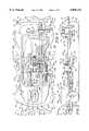
- FIG. 1is a perspective view of a stretcher in accordance with the present invention showing an IV pole extending upwardly above a head end of a patient-support deck, a pair of push bars in a push position having handle posts extending generally horizontally above the head end of the patient-support deck, a brake-steer butterfly pedal located below the push handles, a shroud positioned beneath the patient-support deck and having a top surface formed to include an upwardly-facing storage pan and a downwardly extending skirt appended to the top surface, the skirt defining first and second cavities beneath the top surface, three hydraulic release pedals positioned within the first cavity, and a pump pedal positioned within the second cavity;
- FIG. 2is an end elevation view of the stretcher of FIG. 1 showing the head end of the patient-support deck, a first push bar pivotably mounted to a frame beneath the patient-support deck and positioned in the upward push position having a handle post extending generally horizontally above a patient-support surface of the patient-support deck, a latch plate locking the first push bar in the push position, a second push bar (in phantom) in the push position opposing the first push bar, the second push bar in a down-out-of-the-way position having a handle post below the patient-support surface, and the first push bar (in phantom) in the down-out-of-the-way position opposing the second push bar;
- FIG. 3is a sectional view taken along line 3--3 of FIG. 2 showing the first push bar in the push position having the handle post above the patient-support deck and the first push bar (in phantom) in the down-out-of-the-way position having a portion of the push bar underneath the patient-support deck;
- FIG. 4is a perspective view of the first push bar and a latch assembly showing the first push bar in the down-out-of-the-way position and the latch plate of the latch assembly in an upward release position so that the push bar can swing between the push position and the down-out-of-the-way position;
- FIG. 5is a view similar to FIG. 4 showing the first push bar in the push position, the latch plate in a downward lock position, and an edge of the latch plate defining an opening receiving the first push bar, the edge engaging the first push bar locking the first push bar in the push position;
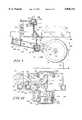
- FIG. 6is a sectional view taken along line 6--6 of FIG. 1 with portions broken away showing the elongated lower frame, movable pedals coupled to the lower frame, a brake-steer mechanism coupled to the lower frame, the brake-steer mechanism including a longitudinally-extending shaft coupled to the casters for controlling the rotational and swivelling movement of the casters and a brake-steer butterfly pedal fixed to the shaft for rotating the shaft when the pedal is depressed by a caregiver, a center wheel movably coupled to the lower frame and coupled to the shaft of the brake-steer mechanism by a linkage assembly, and a shroud carried by the lower frame, the shroud including a top surface having a perimetral edge and a downwardly-extending skirt appended to the edge and defining cavities recessed beneath the top surface, the cavities receiving foot pedals so that At least portions of upwardly-facing foot-engaging surfaces of the foot pedals are positioned beneath the top surface and exposed within the cavities;
- FIG. 7is a side elevation view of the lower frame and shroud with portions broken away showing the brake-steer pedal in a generally horizontal neutral position and the linkage assembly holding the center wheel in a neutral position spaced apart from the floor;
- FIG. 8is an enlarged perspective view of the linkage assembly and the center wheel of FIG. 7 showing the center wheel rotatably coupled to a wheel-mounting bracket and held in the neutral position by the linkage assembly, the linkage assembly including a pivot link fixed to the longitudinal shaft, a connecting link connecting the pivot link to both a frame link that is pivotably coupled to the frame and a bracket link that is pivotably coupled to the wheel-mounting bracket, the connecting link, frame link, and bracket link being coupled to a common pivot pin that translates as the shaft pivots the pivot link;
- FIG. 9is a side elevation view of the center wheel and linkage assembly of FIG. 8 showing the center wheel in the neutral position spaced apart from the floor and showing the center wheel (in phantom) and wheel-mounting bracket (in phantom) moved to a brake position by rotation of the shaft (not shown) to the brake position so that the linkage assembly pivots the wheel-mounting bracket upwardly increasing the separation between the center wheel and the floor;
- FIG. 10is a sectional view taken along line 10--10 of FIG. 9 showing the linkage assembly in the neutral position and movable to the brake position (in phantom) so that as the shaft rotates counter-clockwise in the illustration, the pivot link pulls the connecting link and the common pivot pin toward the shaft, closing the "scissors" defined by the frame link and bracket link so that the bracket link pulls the wheel-mounting bracket upwardly;
- FIG. 11is a view similar to FIG. 9 showing the center wheel lowered to a steer position engaging the floor and showing a first fork and a second fork of the wheel-mounting bracket in an angled configuration having a spring yieldably biasing the center wheel against the floor;
- FIG. 12is a sectional view similar to FIG. 10 taken along line 12--12 of FIG. 11 showing the linkage assembly in the steer position having the pivot link pivoted toward the center wheel thereby opening the scissors defined by the frame link and bracket link, pivoting the wheel-mounting bracket downwardly, and pushing the connecting link and the common pivot pin away from the longitudinal shaft and past the connections of the bracket link to the wheel-mounting bracket and the frame link to the frame to provide the linkage assembly with an "over center" lock;
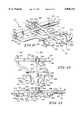
- FIG. 13is an enlarged perspective view of a portion of "single-pedal dual release mechanism" coupled to side members of the lower frame and extending outwardly therefrom showing first, second, and third pedals pivotably coupled to the lower frame by first, second, and third pedal arms, respectively, each pedal having a foot-engaging surface that can be engaged to selectively depress each of the first, second, and third pedals from an upward lock position to a downward release position, the first pedal arm being coupled to the head end of the patient-support surface so that movement of the first pedal to the release position lowers the head end of the patient-support surface relative to the lower frame, the second pedal arm being coupled to the foot end of the patient-support surface so that movement of the second pedal to the release position lowers the foot end of the patient-support surface relative to the lower frame, and the foot-engaging surface of the third pedal being positioned to lie between the foot-engaging surfaces of the first and second pedals, and a cross bar appended to the third pedal arm and engaging the first and second pedal arms so that when the
- FIG. 14is a top plan view of the single-pedal dual release mechanism of FIG. 13 showing an outer edge of the foot-engaging surface of the third pedal extending outwardly past outer edges of the foot-engaging surfaces of the first and second pedals so that a user can easily engage the foot-engaging surface of the third pedal without engaging the foot-engaging surfaces of either of the first and second pedals;
- FIG. 15is a side elevation view of the single-pedal dual release mechanism of FIG. 14 showing the foot-engaging surface of the third pedal positioned to lie above the foot-engaging surfaces of the first and second pedals when each of the first, second, and third pedals are in their respective lock positions so that a user can easily engage the foot-engaging surface of the third pedal without engaging the foot-engaging surfaces of either of the first and second pedals; and
- FIG. 16is a sectional view taken along line 16--16 of FIG. 6 showing the top surface of the shroud projecting above the foot-engaging surfaces of each of the pedals mounted along sides of the lower frame, the pedals being received by cavities defined by the downwardly and inwardly extending skirt of the shroud positioned underneath the top surface of the shroud so that the foot-engaging surfaces of the pedals are exposed and are available to the caregiver when the shroud is installed on the stretcher.
- a stretcher 20 in accordance with the present inventionincludes a frame 22 having an upper frame 24, a lower frame 26 covered by a shroud 52, a head end 32, a foot end 34, an elongated first side 36, and an elongated second side 38 as shown in FIG. 1.
- head end 32will be used to denote the end of any referred-to object that is positioned to lie nearest the head end 32 of stretcher 20
- foot end 34will be used to denote the end of any referred-to object that is positioned to lie nearest the foot end 34 of stretcher 20.
- first side 36will be used to denote the side of any referred-to object that is positioned to lie nearest the first side 36 of stretcher 20 and the phrase “second side 38" will be used to denote the side of any referred-to object that is positioned to lie nearest the second side 38 of stretcher 20.
- drive means 28includes a head end hydraulic cylinder 46 and a foot end hydraulic cylinder 48, shown in FIGS. 6 and 7, which are covered by flexible rubber boots 50 as shown in FIG. 1.
- Head end hydraulic cylinder 46controls the vertical position of head end 32 of upper frame 24 relative to lower frame 26 and foot end hydraulic cylinder 48 controls the vertical position of foot end 34 of upper frame 24 relative to lower frame 26. It will be appreciated that various mechanical and electro-mechanical actuators and drivers may be used to raise and lower the upper frame 24 relative to the lower frame 26 without exceeding the scope of the invention as presently perceived.
- drive meansin the specification and in the claims is intended to cover all types of mechanical, electromechanical, hydraulic, and pneumatic mechanisms for raising and lowering portions of stretcher 20, including manual cranking mechanisms of all types, and including combinations thereof such as hydraulic cylinders in combination with electromechanical pumps for pressurizing fluid received by the hydraulic cylinders.
- a patient-support deck 30is carried by upper frame 22 as shown in FIG. 1 and has a head end 32, a foot end 34, a first side 36, and a second side 38.
- a mattress 40 having an upwardly-facing patient-support surface 42is supported by the patient-support deck 30.
- Illustrative stretcher 20also includes a pair of collapsible side rails 62 mounted to upper frame 24 adjacent to first and second elongated sides 36, 38 of patient-support deck 30 as shown in FIG. 1.
- An IV pole 64 for holding solution containers or other objects at a position elevated above patient-support surface 42is pivotably attached to the upper frame 24 and can be pivoted between a lowered horizontal position alongside the patient-support deck 30 and a generally vertical raised position shown in FIG. 1.
- Casters 44are mounted to lower frame 26 so that the stretcher 20 can be rolled over a floor or other surface across which a patient is being transported, hereinafter referred to as floor 43.
- Several foot pedals 54are pivotably coupled to lower frame 26 and are coupled to drive means 28 to control the operation of drive means 28 and thus the vertical movement of head end 32 and foot end 34 of upper frame 24 relative to lower frame 26.
- a brake pedal 56is coupled to lower frame 26 to control braking of the casters 44 and a brake-steer butterfly pedal 58 is coupled to lower frame 26 to control both the braking of casters 44 and the release of braked casters 44.
- Each of foot pedals 54, brake pedal 56, and brake-steer pedal 58extends outwardly from lower frame 26.
- a shroud 52covers the lower frame 26 as shown in FIG. 1.
- Shroud 52includes a generally horizontal top surface 272 extending over lower frame 26 and over several of foot pedals 54 so that the size of top surface 272 of shroud 52 can be maximized.
- first push bar 66is mounted to head end 32 of upper frame 24 adjacent to first elongated side 36 of the patient-support deck 30 and a second push bar 68 is mounted to head end 32 of upper frame 24 adjacent to second elongated side 38 of patient-support deck 30 as shown in FIG. 1.
- first and second push bars 66, 68is independently movable between a raised push position shown in FIGS. 1-3 (second push bar 68 is in phantom in FIG. 2) and a lowered down-out-of-the-way position shown in FIGS. 2-4 (first push bar 66 is in phantom in FIGS. 2 and 3).
- Push bars 66, 68swing from the push position to the down-out-of-the-way position in the direction indicated by arrow 110 shown in FIG. 5, and from the down-out-of-the-way position to the push position in the direction of arrow 118 shown in FIG. 4.
- first and second push bars 66, 68When first and second push bars 66, 68 are in the push position, a caregiver can grip the push bars 66, 68 to maneuver the stretcher 20 over the floor 43. When the push bars 66, 68 are in the down-out-of-the-way position, push bars 66, 68 are below and out of the way of patient-support surface 42, thus maximizing the caregiver's access to a patient on patient-support surface 42 when the caregiver is positioned adjacent to head end 32 of stretcher 20.
- First and second push bars 66, 68each include a handle post 70 that is grasped by the caregiver when the caregiver moves stretcher 20, a pivot post 74 pivotably coupled to upper frame 24, and a bent extension post 72 connecting handle post 70 to pivot post 74.
- the respective handle post 70, extension post 72, and pivot post 74 of each push bar 66, 68are integrally connected in a serpentine-like configuration as shown in FIGS. 2-4.
- the pivot post 74 of push bar 66is pivotably coupled to a pair of spaced-apart flanges 76, shown best in FIG. 4, which receive pivot post 74 therebetween.
- Flanges 76are appended to a bracket 78 which is attached to a corner of upper frame 24 adjacent to head end 32 and adjacent to first side 36 of patient-support deck 30 as shown in FIGS. 2-5, and flanges 76 extend downwardly and inwardly therefrom away from first side 36 of upper frame 24.
- a pivot pin 80extends between flanges 76 and is received by opposing openings 81 formed in pivot post 74 to rotatably couple the pivot post 74 of push bar 66 to pivot pin 80 and to flanges 76 for pivoting movement of pivot post 74 and push bar 66 relative to flanges 76 about a pivot axis 82 shown in FIGS. 2 and 3 and defined by pivot pin 80 shown in FIG. 4.
- Push bar 68is similarly connected to the upper frame 24 but is configured to oppose push bar 66 and to pivot about pivot axis 84 shown in FIG. 2.
- Each angled pivot axis 82, 84projects downwardly and outwardly away from first and second sides 36, 38, respectively, of patient-support deck 30 as shown best in FIG. 2. Additionally, each angled pivot axis 82, 84 is positioned to lie in a transverse plane indicated by line c (plane c extends perpendicular to the page in the illustration) as shown best in FIG. 3.
- handle post 70 of each push bar 66, 68extends above patient-support surface 42 as shown in FIGS. 2 and 3.
- ends 86 of each handle post 70project inwardly toward one another as shown in FIG. 2.
- pivot post 74 of push bar 66extends from a first end 85 coupled to pivot pin 80 to a second end 87 that is integrally appended to extension post 72 at a position outside of head end 32 of upper frame 24 and adjacent to first side 36 of upper frame 24 when push bar 66 is in the push position as shown in FIGS. 3 and 5.
- extension post 72angles upwardly from second end 87 of pivot post 74 as shown in FIG. 3 and a second portion of extension post 72 extends generally vertically upwardly from the first portion of extension post 72.
- the second portion of extension post 72is integrally appended to handle post 70 above patient-support surface 42.
- pivot post 74, extension post 72, and handle post 70 of push bar 68are similarly oriented with respect to second elongated side 38 of upper frame 24 and in opposition to push bar 66 when push bar 68 is in the push position.
- Each push bar 66, 68can be independently pivoted about its respective pivot axis 82, 84 from the push position to the down-out-of-the-way position shown in FIGS. 2 and 3 so that push bars 66, 68 are beneath a horizontal plane indicated by line a defined by patient-support deck 30 (plane a extends perpendicular to the page in the illustration).
- push bars 66, 68are in the down-out-of-the-way position, push bars 66, 68 are fully beneath upper frame 24 and pivot post 74 is rotated around so that it extends from first end 85 of pivot post 74 coupled to pivot pin 80 to second end 87 of pivot post 74 generally toward foot end 34 of stretcher 20.
- push bars 66, 68When push bars 66, 68 are in the down-out-of-the-way position, push bars 66, 68 abut one another in a "folded-eyeglass" configuration as shown in FIG. 2 in which ends 86 of the handle posts 70 project generally upwardly and away from each other.
- second push bar 68When in the folded-eyeglass configuration, either second push bar 68 can be nearer head end 32 than first push bar 66 as shown in FIG. 2 or this arrangement can be reversed so that first push bar 66 is nearer head end 32 than second push bar 68.
- Each push bar 66, 68can be locked in its push position by respective first and second latch plates 88, 90.
- Each latch plate 88, 90is pivotably mounted to upper frame 24 adjacent to head end 32 of the patient-support deck 30 as shown in FIGS. 2-5.
- Latch plate 90 and the operation of latch plate 90is substantially similar to that of latch plate 88.
- latch plate 88 and the operation of latch plate 88applies as well to latch plate 90 unless specifically noted otherwise.
- Latch plate 88is mounted to upper frame 24 near side 36 of upper frame 24 for pivoting movement about a longitudinally-extending first latch pivot axis 92 as shown best in FIG. 3.
- Latch plate 88can swing about pivot axis 92 between an upward release position away from push bar 66 as shown in FIG. 4 and a downward lock position engaging push bar 66 as shown in FIGS. 2, 3, and 5.
- Latch plate 88pivots upwardly about pivot axis 92 in a direction indicated by arrow 112 from the lock position to the release position to release locked push bar 66 so that push bar 66 can swing freely in direction 110 and direction 118 between the push position and the down-out-of-the-way position.
- latch plate 88pivots downwardly under the force of gravity about longitudinal pivot axis 92 in a direction indicated by arrow 100 when latch plate 88 moves from the release position shown in FIG. 4 to the lock position shown in FIGS. 2, 3, and 5.
- Latch plate 88includes a release tab 114 that the caregiver can engage to manually pivot latch plate 88 upwardly from the lock position to the release position.
- Latch plate 88is also formed to include an edge 96 defining an opening 98 that receives pivot post 74 of push bar 66 when push bar 66 is in the push position and latch plate 88 is in the downward lock position.
- Edge 96includes a locking edge 97 engaging push bar 66 to lock push bar 66 in the push position when latch plate 88 is in the lock position, as shown in FIG. 2.
- Edge 96 of latch plate 88is additionally formed to include a curved cam edge 116 adjacent to opening 98 and locking edge 97.
- pivot post 74swings in direction 118 to engage cam edge 116 and apply a contact force thereto, pivoting latch plate 88 upwardly to the release position so that opening 98 can receive pivot post 74.
- latch plate 88automatically pivots in direction 100 under the force of gravity to the lock position so that locking edge 97 engages push bar 66 to lock push bar 66 in the push position.
- a stop tab 120is fixed to upper frame 24 adjacent to first side 36 of upper frame 24 as shown in FIGS. 4 and 5. Stop tab 120 is received in opening 98 of latch plate 88 to engage edge 96 of latch plate 88 when latch plate 88 is in the lock position and push bar 66 is in the down-out-of-the-way position to stop the downward movement of latch plate 88. Stop tab 120 is positioned to orient cam edge 116 of latch plate 88 to contact pivot post 74 of push bar 66 during movement of push bar 66 from the down-out-of-the-way position to the push position.
- stretcher 20includes first and second push bars 66, 68 each having a handle post 70 that is positioned for convenient access by a caregiver pushing stretcher 20 when first and second push bars 66, 68 are in the push position as shown in FIG. 1.
- Latch plates 88, 90are provided for locking push bars 66, 68 in the push position and each latch plate 88, 90 includes a release tab 114 that the caregiver can engage to rotate latch plates 66, 68 to the upward release position.
- Rotating latch plates 66, 68 to the release positionreleases push bars 66, 68 so that push bars 66, 68 can pivot downwardly about angled pivot axes 82, 84 to store below patient-support deck 30 in the down-out-of-the-way position.
- Push bars 66, 68can be independently folded downwardly about angled pivot axes 82, 84 to the respective down-out-of-the-way positions to maximize the access of the caregiver to the patient carried on patient-support surface 42 of stretcher 20.
- the caregivercan swing each push bar 66, 68 upwardly from the down-out-of-the-way positions to lock each push bar 66, 68 in the push position as shown in FIGS. 1 and 2.
- stop tab 120holds latch plate 88 so that cam edge 116 is positioned to lie adjacent to pivot post 74 of push bar 66.
- pivot post 74applies a contact force to cam edge 116 of latch plate 88 to automatically pivot latch plate 88 upwardly.
- latch plate 88automatically drops to the lock position so that locking edge 97 engages push bar 66 to automatically lock push bar 66 in the push position.
- stretcher 20includes brake pedal 56 positioned at the foot end 34 of stretcher 20 and brake-steer pedal 58 positioned at the head end 32 of stretcher 20 as shown in FIG. 1.
- a brake-steer shaft 60extends longitudinally along the length of the stretcher 20 underneath shroud 52 as shown in FIGS. 6 and 7 and is connected to both brake pedal 56 and brake-steer pedal 58.
- Brake-steer shaft 60is mounted to lower frame 26 to rotate about a longitudinal pivot axis 122. Movement of either brake pedal 56 or brake-steer pedal 58 by a caregiver causes shaft 60 to rotate about pivot axis 122.
- Brake-steer shaft 60is coupled to lower frame 26 by three sets of flanges 124 as shown in FIG. 6, each set including an upper flange 125 and a lower flange 127 extending outwardly from a lower frame member 126.
- One set of flanges 124is located near head end 32 of brake-steer shaft 60
- a second set of flanges 124is located near the middle of brake-steer shaft 60
- a third set of flanges(not shown) is located near foot end 34 of brake-steer shaft 60.
- a pair of caster-braking linkages 128are fixed to brake-steer shaft 60 at positions near head end 32 of brake-steer shaft 60 and foot end 34 of brake-steer shaft 60 as shown in FIGS. 6 and 7.
- the brake-steer pedal 58is in a generally horizontal position as shown in FIGS. 6 and 7 and the casters 44 are free to swivel and rotate.
- the caregivercan depress a braking portion 59 of brake-steer pedal 58 to rotate brake-steer shaft 60 about longitudinal pivot axis 122 in a braking direction indicated by arrow 140 shown in FIG.
- brake-steer shaft 60When brake-steer shaft 60 is in the brake position, braking portion 59 of brake-steer pedal 58 is angled downwardly toward first side 36 of stretcher 20. From the brake position, the caregiver can depress a steering portion 61 of brake-steer pedal 58 to rotate the brake-steer shaft 60 about longitudinal pivot axis 122 back to the neutral position. When brake-steer shaft 60 is in the neutral position, the caregiver can depress steering portion 61 of brake-steer pedal 58 to rotate brake-steer shaft 60 in a steering direction indicated by arrow 144 shown in FIG. 8 to a steer position having braking portion 59 angled upwardly and steering portion 61 of brake-steer pedal 58 angled downwardly toward second side 38 of stretcher 20.
- a center wheel 138is pivotably coupled to lower frame 26 by a wheel-mounting bracket 136 and wheel-mounting bracket 136 is coupled to the brake-steer shaft 60 by linkage assembly 134 as shown in FIGS. 6, 7, and 8.
- Rotation of brake-steer shaft 60 about axis 122changes the position of center wheel 138 relative to floor 43.
- linkage assembly 134holds wheel-mounting bracket 136 and center wheel 138 off of floor 43 by a slight distance 139.
- Preferred and illustrative center wheel 138is spaced apart from the floor 43 by approximately 0.5 inches (1.3 cm) when brake-steer shaft 60 is in the neutral position.
- Second distance 141is sufficient to allow equipment such as the base (not shown) of an overbed table (not shown) to be positioned underneath center wheel 138 of stretcher 20. Second distance 141 of preferred and illustrative center wheel 138 is approximately 3.5 inches (8.9 cm).
- Wheel-mounting bracket 136includes a first fork 148 and a second fork 150 pivotably coupled to first fork 148.
- First fork 148is pivotably coupled at a first end 147 to lower frame 26 for pivoting movement about a first transverse pivot axis 152 as shown in FIGS. 9 and 11.
- a second end 149 of first fork 148is pivotably coupled to second fork 150 so that first and second forks 148, 150 can pivot relative to one another about a second transverse pivot axis 154 shown in FIG. 8.
- a head end portion 151 of second fork 150extends from second transverse pivot axis 154 toward the head end 32 of stretcher 20.
- Center wheel 138is mounted to head end portion 151 of second fork 150 for rotation about an axis of rotation 156 as shown in FIG. 8.
- a foot end portion 153 of second fork 150extends from second transverse pivot axis 154 toward the foot end 34 of stretcher 20 and is received by a space 155 defined by two spaced-apart prongs 157, 159 of first fork 148.
- An end plate 158is fixed to foot end portion 153 of second fork 150 as shown best in FIGS. 8 and 11.
- a vertically oriented spring 160connects end plate 158 of second fork 150 to a frame bracket 162 mounted to lower frame 26 as shown in FIGS. 8-12.
- spring 160yieldably biases end plate 158 and foot end portion 153 of second fork 150 upwardly so that head end portion 151 of second fork 150 and center wheel 138 are yieldably biased downwardly.
- End plate 158has a pair of transversely extending barbs 164 that are appended to a lower end of end plate 158 and that are positioned to engage the bottom of first fork 148 when first and second forks 148, 150 are in an "in-line" configuration defining a straight bracket as shown in FIGS. 8 and 9.
- barbs 164stop the upward movement of end plate 158 at the in-line configuration to limit the downward movement of head end portion 151 and center wheel 138 relative to first fork 148 as spring 160 biases end plate 158 of second fork 150 upwardly.
- spring 160has a spring force between approximately 36 and 40 pounds-force (160-178N).
- spring 160biases second fork 150 away from the angled configuration of first and second forks 148, 150 and toward the in-line configuration so that center wheel 138 is biased to a position past the plane of floor 43 and past the plane defined by wheels 132 of casters 44 when center wheel 138 is deployed as shown best in FIG. 11.
- floor 43limits the downward movement of deployed center wheel 138.
- spring 160cooperates with first and second forks 148, 150 to maintain contact between center wheel 138 and floor 43.
- the plane defined by the bottoms of wheels 132 of casters 44is not necessarily coplanar with floor 43.
- spring 160 and first and second forks 148, 150cooperate to maintain engagement of the deployed center wheel 138 against floor 43.
- Illustrative and preferred wheel-mounting bracket 136can maintain engagement between deployed center wheel 138 and floor 43 when floor 43 beneath center wheel 138 is spaced apart up to approximately 1 inch (2.5 cm) beneath the plane defined by the bottoms of wheels 132 of casters 44. Additionally, illustrative and preferred wheel-mounting bracket 136 allows deployed center wheel 138 to pass over a threshold that is approximately 1 inch (2.5 cm) above the plane defined by the bottoms of wheels 132 of casters 44 without forcing second pivot axis 154 upwardly relative to lower frame 26 and causing linkage assembly 134 to move out of the steer position into the neutral position.
- a frame bracket 162is mounted to lower frame 26 as shown in FIG. 8.
- Linkage assembly 134is connected to frame bracket 162 by a first bent-cross bracket 190 positioned to lie generally above linkage assembly 134 and by an upper pivot pin 192 coupled to first bent-cross bracket 190.
- linkage assembly 134is connected to wheel-mounting bracket 136 by a second bent-cross bracket 194 positioned to lie generally beneath linkage assembly 134 and by a lower pivot pin 196 coupled to second bent-cross bracket 194.
- Linkage assembly 134is also connected to brake-steer shaft 60 as shown in FIG. 8.
- a pivot link 168 of linkage assembly 134is fixed to brake-steer shaft 60 and a connecting link 170 extends from pivot link 168 to a "common" pivot pin 188.
- a bracket link 174extends from common pivot pin 188 to lower pivot pin 196 of second bent-cross bracket 194 and a frame link 172 extends from common pivot pin 188 to upper pivot pin 192 of first bent-cross bracket 190 as shown in FIGS. 8, 10, and 12.
- Pivot link 168includes a first end 167 having an aperture 180 and a collar 184 surrounding aperture 180 and a second end 169 spaced apart from first end 167.
- Brake-steer shaft 60extends through aperture 180 of pivot link 168 and a set screw 182 is threaded through collar 184 to fix pivot link 168 to brake-steer shaft 60.
- pivot link 168is fixed to brake-steer shaft 60 and pivots about longitudinal axis 122 when brake-steer shaft 60 rotates about axis 122.
- Connecting link 170includes a link member 176 and an eye bolt 178.
- Second end 169 of pivot link 168is pivotably coupled to link member 176 as shown in FIGS. 8, 10, and 12.
- Link member 176is formed to include a flange 186 and eye bolt 178 screws into flange 186 to connect eye bolt 178 to link member 176.
- Eye bolt 178is formed to include an opening (not shown) that rotatably receives common pivot pin 188.
- Frame link 172is formed to include a first opening 171 rotatably receiving common pivot pin 188 and a second opening 173 spaced apart from first opening 171 and rotatably receiving upper pivot pin 192 of first bent-cross bracket 190 as best shown in FIGS. 9 and 11 so that frame link 172 can pivot relative to common pivot pin 188 and relative to first bent-cross bracket 190.
- Bracket link 174is also formed to include a first opening 175 rotatably receiving common pivot pin 188 and a second opening 177 spaced apart from first opening 175 and rotatably receiving lower pivot pin 196 of second bent-cross bracket 194 as shown in FIGS. 8, 9, and 11 so that bracket link 174 can pivot relative to common pivot pin 188 and relative to second bent-cross bracket 194.
- connecting link 170, frame link 172, and bracket link 174are each pivotably connected to common pivot pin 188.
- First bent-cross bracket 190 and upper pivot pin 192are positioned vertically above second bent-cross bracket 194 and lower pivot pin 196 as shown in FIGS. 10 and 12.
- eye bolt 178longitudinally separates frame link 172 and bracket link 174 as shown in FIGS. 9 and 11. To compensate for this separation, first bent-cross bracket 190 is disposed slightly toward foot end 34 of stretcher 20 relative to second bent-cross bracket 194.
- First bent-cross bracket 190includes a pair of downwardly extending side flanges 198 mounted to frame bracket 162 by pivot pins 199.
- First bent-cross bracket 190also includes a pair of downwardly extending center flanges 200 each of which is formed to include an aperture 210 through which upper pivot pin 192 extends as shown in FIG. 8.
- Frame link 172is coupled to upper pivot pin 192 between downwardly extending center flanges 200 of first bent-cross bracket 190.
- Second bent-cross bracket 194includes a pair of upwardly extending side flanges 212 rotatably mounted to both first and second forks 148, 150 by pivot pins 213 at second transverse pivot axis 154 so that pivot pins 213 define pivot axis 154 of second fork 150 relative to first fork 148.
- Second bent-cross bracketalso includes a pair of upwardly extending center flanges 214 each of which is formed to include an aperture 216 though which the lower pivot pin 196 extends.
- Bracket link 174is coupled to lower pivot pin 196 between upwardly extending center flanges 214 of second bent-cross bracket 194.
- Frame link 172 and bracket link 174form a "scissors-like" scissors arrangement as shown in FIG. 10.
- pivot link 168pivots away from wheel-mounting bracket 136 pulling connecting link 170 and common pivot pin 188 toward brake-steer shaft 60 in the direction indicated by arrow 218.
- First bent-cross bracket 190is vertically fixed relative to lower frame 26 and second bent-cross bracket 194 is fixed to wheel-mounting bracket 136 which is fixed in the transverse direction but is pivotably mounted to lower frame 26 for upward and downward pivoting movement relative to lower frame 26. Movement of common pivot pin 188 in direction 218 closes the scissors arrangement formed by frame link 172 and bracket link 174 pulling bracket link 174 upwardly. Pulling bracket link 174 upwardly pivots wheel-mounting bracket 136 in direction 142 and lifts center wheel 138 off of the floor 43.
- pivot link 168pivots toward wheel-mounting bracket 136 pushing connecting link 170 and common pivot pin 188 away from brake-steer shaft 60 in the direction indicated by arrow 220.
- Movement of common pivot pin 188 in direction 220opens the scissors arrangement formed by frame link 172 and bracket link 174 and pushes bracket link 174 downwardly.
- Pushing bracket link 174 downwardlypivots wheel-mounting bracket 136 in direction 146 thus deploying center wheel 138 into contact with the floor 43.
- pivot link 168contacts lower frame member 126 as shown in FIG. 12 stopping brake-steer shaft 60 from further rotation in direction 144.
- pivot link 168 contacts lower frame member 126common pivot pin 188 is in an "overcenter position" away from brake-steer shaft 60 and beyond a vertical plane defined by upper and lower pivot pins 192, 196 and indicated by line b (plane b extends perpendicular to the page in the illustration) so that the scissors arrangement formed by frame link 172 and bracket link 174 is in a generally fully-opened position.
- stretcher 20includes brake pedal 56 and brake-steer pedal 58 connected to longitudinally extending brake-steer shaft 60. Actuation of brake pedal 56 or brake-steer pedal 58 by the caregiver simultaneously controls the position of center wheel 138 and braking of casters 44. Brake-steer pedal 58 has a horizontal neutral position where center wheel 138 is distance 139 above floor 43 and casters 44 are free to rotate and swivel.
- the caregivercan push brake pedal 56 or braking portion 59 of brake-steer pedal 58 down to rotate brake-steer shaft 60 by 30° (degrees) to the brake position to brake casters 44.
- pivot link 168pivots away from wheel-mounting bracket 136 pulling connecting link 170 and common pivot pin 188 in direction 218 and closing the scissors arrangement of frame link 172 and bracket link 174 to lift center wheel 138 distance 141 above floor 43.
- the caregivercan also push steering portion 61 of brake-steer pedal 58 down to rotate brake-steer shaft 60 by 30° (degrees) past the neutral position to the steer position in which casters 44 are free to rotate and swivel.
- pivot link 168pivots toward the wheel-mounting bracket 136 pushing connecting link 170 and common pivot pin 188 in direction 220 and opening the scissors arrangement of frame link 172 and bracket link 174 to deploy center wheel 138 to engage floor 43 with enough pressure to facilitate steering stretcher 20.
- second fork 150 of wheel-mounting bracket 136pivots relative to first fork 148 and relative to lower frame 26.
- Second fork 150 and center wheel 138which is mounted to second fork 150, is spring-biased against floor 43 so that stretcher 20 or center wheel 138 can pass over an obstacle such as a 1 inch (2.5 cm) high threshold without disengaging center wheel 138 from floor 43.
- illustrative stretcher 20also includes foot pedals 54 which control the operation of drive means 28, which illustratively include head end and foot end hydraulic cylinders 46, 48.
- Foot pedals 54are coupled to drive means 28 and include pump pedals 264 illustratively located adjacent to each of the first and second sides 36, 38 as shown in FIG. 6 and that the caregiver can pump to raise patient-support surface 42.
- Each pump pedal 264is pivotably coupled to lower frame 26 and operatively coupled to both head end hydraulic cylinder 46 and foot end hydraulic cylinder 48. The caregiver can pump either pump pedal 264 to raise patient-support surface 42 relative to lower frame 26 from a lower down position until the desired elevation of patient-support surface 42 is achieved up to an upper raised position.
- foot pedals 54also include pedals 224, 226, 228, 266, 268 that are pivotably coupled to lower frame 26 along first side 36 and second side 38 of stretcher 20, that extend outwardly therefrom, and that are each operatively coupled to either one or both of head end and foot end hydraulic cylinders 46, 48.
- pedals 224, 226, 228, 266, 268can be depressed by the caregiver to lower at least a portion of patient-support surface 42 from the raised position until the desired elevation of patient-support surface 42 is achieved down to the down position.
- a first "single-pedal dual release mechanism” 222is located along first side 36 of stretcher 20 and a second single-pedal dual release mechanism 223 is located along second side 38 of stretcher 20 as shown in FIG. 6.
- Single pedal-dual release mechanism 222is described in detail below with respect to FIGS. 13-15.
- Second single pedal-dual release mechanism 223is configured and operated in substantially the same way as first single pedal-dual release mechanism 222.
- first single pedal-dual release mechanism 222 of first side 36 of stretcher 20is also descriptive of second single pedal-dual release mechanism 223 and applies thereto unless otherwise specified.
- Single-pedal dual release mechanism 222includes first foot pedal 224 which is attached to a first pedal arm 230, second foot pedal 226 which is attached to a second pedal arm 232, and third foot pedal 228 which is attached to a third pedal arm 234 as shown best in FIG. 13.
- First pedal arm 230is pivotably coupled to lower frame 26 and is operatively coupled to head end hydraulic cylinder 46 so that first foot pedal 224 is movable between an upward lock position and a downward release position. Depressing first foot pedal 224 to move first foot pedal to the release position lowers head end 32 of patient-support surface 42 relative to lower frame 26.
- second pedal arm 232is pivotably coupled to lower frame 26 and is operatively coupled to foot end hydraulic cylinder 48 for movement between an upward lock position and a downward release position so that depressing second foot pedal 226 to move second foot pedal 226 to the release position lowers foot end 34 of patient-support surface 42 relative to lower frame 26.
- Third pedal arm 234is positioned to lie between first and second pedal arms 230, 232 and is pivotably coupled to lower frame 26 for movement between an upward lock position and a downward release position.
- third pedal arm 234pivots about a longitudinally-extending pivot pin 236 mounted to a pivot bracket 238 which is fixed to a top surface 239 of lower frame member 126 as shown in FIG. 13.
- a cross bar 240is appended to third pedal arm 234 and extends longitudinally therefrom toward head end 32 of stretcher 20 and rests upon first pedal arm 230 as shown in FIGS. 13-15.
- Cross bar 240also extends longitudinally from third pedal arm 234 toward foot end 34 of stretcher 20 and rests upon second pedal arm 232.
- cross bar 240depresses first and second pedal arms 230, 232 and moves pedal arms 230, 232 from their respective lock positions to their respective release positions so that both head end and foot end hydraulic cylinders 46, 48 lower generally simultaneously and at approximately the same rate.
- a pedal arm first collar 242is fixed to a bottom surface 243 of lower frame 26 and is formed to include an opening 241 as shown in FIGS. 13 and 15.
- First pedal arm 230is rotatably received by opening 241 so that first pedal 224 is pivotably attached to lower frame 26 by first pedal arm 230 and collar 242.
- a pedal arm second collar 244is fixed to bottom surface 243 of lower frame 26, is spaced apart from first collar 242, and is formed to include an opening 245.
- Second pedal arm 232is rotatably received by opening 245 so that second foot pedal 226 is pivotably attached to lower frame 26 by second pedal arm 232 and collar 244.
- First pedal arms 230 of both single pedal-dual release mechanisms 222, 223are integrally connected to one another as a one-piece first bell crank 225 and as shown in FIG. 6 so that pivoting first foot pedal 224 of first single pedal-dual release mechanism 222 causes first foot pedal 224 of second single pedal-dual release mechanism 223 also to pivot.
- the second pedal arms 232 of both single pedal-dual release mechanisms 222, 223are integrally connected to one another as a one-piece second bell crank 227.
- First collar 242 of first mechanism 222 and first collar 242 of second mechanism 223cooperate to define a single transverse pivot axis 246 about which first pedal arms 230 pivot as shown in FIGS. 6, 7, and 13.
- second collar 244 of first mechanism 222 and second collar of 244 of second mechanism 223cooperate to define a single transverse pivot axis 248 about which second pedal arms 232 pivot.
- pivot pin 236defines a longitudinal pivot axis 250 about which third pedal arm 234 pivots.
- third pedal arm 234pivots about longidudinally-extending pivot axis 250 defined by pivot pin 236, it is within the scope of the invention as presently perceived to provide a third pedal arm that pivots about a pivot axis that extends in a direction other than the longitudinal direction so long as the third pedal arm interacts with first and second pedal arms 230, 232 as described above.
- the third pedal armcould be a bent "bell crank-shaped" arm mounted to a collar fixed to bottom surface 243 of lower frame 26 so that the third pedal arm pivots about a transversely-extending pivot axis, without exceeding the scope of the invention as presently perceived.
- First foot pedal 224has a first foot-engaging surface 252
- second foot pedal 226has a second foot-engaging surface 254
- third foot pedal 228has a third foot-engaging surface 256 as shown in FIGS. 13-16.
- Foot-engaging surfaces 252, 254, 256are configured to allow the caregiver to selectively step on a desired one of foot-engaging surfaces 252, 254, 256 without stepping on the other foot-engaging surfaces.
- both first and second foot-engaging surfaces 252, 254are angled downwardly and outwardly away from lower frame 26 as shown in FIGS. 15 and 16, whereas third foot-engaging surface 256 is a generally horizontal upwardly-facing surface.
- third foot-engaging surface 256is positioned to lie in an elevated position above first and second foot-engaging surfaces 252, 254 as shown in FIGS. 15 and 16.
- First foot pedal 224has a first outer edge 258, second foot pedal 226 has a second outer edge 260, and third foot pedal 228 has a third outer edge 262 as shown in FIG. 13.
- An extreme outer portion 263 of third outer edge 262 of third foot pedal 228extends to a position that is further away from lower frame 26 than extreme outer portions 259, 261 of first and second outer edges 258, 260, respectively, of first and second foot pedals 224, 226 as shown in FIG. 14.
- the positioning of first, second, and third outer edges 258, 260, 262 in this manneralso aids the caregiver in engaging only the desired foot-engaging surface.
- first pedal arm 230rotates about transversely-extending pivot axis 246 to actuate a release portion (not shown) of illustrative head end hydraulic cylinder 46, lowering head end 32 of patient-support surface 42.
- second pedal arm 232rotates about transversely-extending pivot axis 248 to actuate a release portion (not shown) of illustrative foot end hydraulic cylinder 48, lowering foot end 34 of patient-support surface 42.
- cross bar 240engages first and second pedal arms 230, 232 so that both pedal arms 230, 232 rotate downwardly about their respective transversely-extending pivot axes 246, 248 and reach their respective release positions at generally the same time.
- the caregivercan lower head end 32 and foot end 34 of patient-support surface 42 together or separately by selectively depressing third foot pedal 228 to lower head end 32 and foot end 34 of patient-support surface 42 together, or separately depressing one of first and second foot pedals 224, 226 of single-pedal dual hydraulic release mechanisms 222, 223 to separately lower head end 32 or foot end 34, respectively.
- stretcher 20includes two single pedal-dual release mechanisms 222, 223 that allow the caregiver to evenly lower head end 32 and foot end 34 of patient-support surface 42.
- Each single pedal-dual hydraulic release mechanism 222, 223includes first pedal 224 which lowers head end 32 of patient-support surface 42, second pedal 226 which lowers foot end 34 of patient-support surface 42, and third pedal 228 positioned between first and second pedals 226, 228.
- First, second, and third pedals 224, 226, 228are attached at ends of first, second, and third pedal arms 230, 232, 234.
- Pedal arms 230, 232, 234are pivotably coupled to lower frame 26 and first and second pedal arms 230, 232 pivot about transversely-extending pivot axes 246, 248.
- First pedal arm 230is spaced apart from second pedal arm 232 and third pedal arm 234 is positioned to lie therebetween.
- Cross bar 240is appended to third pedal arm 234 and rests on first and second pedal arms 230, 232 to hold third pedal 228 above first and second pedals 224, 226.
- first foot pedal 224 and then second foot pedal 226, second foot pedal 226 and then first foot pedal 224, or attempting to simultaneously engage and depress both first and second foot pedals 224, 226 to lower both head and foot ends 32, 34 of patient-support surface 42the caregiver, while standing along either first side 36 or second side 38 of stretcher 20 can depress third pedal 228 so that cross bar 240 lowers first and second pedal arms 230, 232 which, in turn, releases drive means 28 of both head end 32 and foot end 34 of stretcher 20 at the same time to evenly lower patient-support surface 42.
- the caregivercan depress first pedal 224 to lower only head end 32 of patient-support surface 42 or the caregiver can depress second pedal 226 to lower only foot end 34 of patient-support surface 42.
- stretcher 20has a redundant first lowering pedal 266, a redundant second lowering pedal 268, and a redundant pump pedal 270 all of which are positioned at foot end 34 of stretcher 20 as shown in FIGS. 1 and 6.
- First lowering pedal 266is pivotably coupled to lower frame 26 and is illustratively operatively coupled to head end hydraulic cylinder 46 for lowering head end 32 of patient-support surface 42.
- Second lowering pedal 268is pivotably coupled to lower frame 26 and is illustratively operatively coupled to foot end hydraulic cylinder 48 for lowering foot end 34 of patient-support surface 42.
- Pump pedal 270is pivotably coupled to lower frame 26 and is illustratively operatively coupled to both head and foot end hydraulic cylinders 46, 48 for raising patient-support surface 42.
- Stretcher 20is outfitted with a shroud 52 covering lower frame 26 and many components attached to lower frame 26 including casters 44, center wheel 138, brake-steer shaft 60, caster-braking linkages 128, transverse brake rods 130, linkage assembly 134, and wheel-mounting bracket 136 as shown in FIGS. 1, 6, and 16.
- Shroud 52has a top surface 272 formed to include a storage pan 274. Objects (not shown) can be placed in storage pan 274 and carried by stretcher 20.
- Top surface 272 of shroud 52extends laterally over portions of first, second, third, and pump pedals 224, 226, 228, 264 to a perimetral edge 277 of top surface 272 as shown in FIG. 6.
- the extension of top surface 272 over portions of first, second, third, and pump pedals 224, 226, 228, 264allows the size of top surface 272 and the size of a storage pan 274 formed in top surface 272 to be maximized.
- a peripheral skirt 276extends generally downwardly from perimetral edge 277 to a lowermost bottom edge 280 of shroud 52 which is positioned below at least portions of pedals 224, 226, 228, 264 so that portions of peripheral skirt 276 are positioned to lie behind pedals 224, 226, 228, 264.
- Peripheral skirt 276 and top surface 272cooperate to define an interior region 278 as shown in FIG. 16.
- Perimetral edge 277includes first and second spaced-apart straight side portions 279, 281 as shown in FIGS. 6 and 16.
- bottom edge 280includes first and second spaced-apart side portions 283, 285.
- side portions 283, 285 of bottom edge 280are "sickle-shaped" as shown in FIG. 6.
- Peripheral skirt 276includes first and second sides 273, 275 extending respectively between side portions 279, 281 of perimetral edge 277 and side portions 283, 285 of bottom edge 280. Each side 273, 275 of peripheral skirt 276 is formed to define a first cavity 282 and a second cavity 284 as shown in FIG. 16. Second cavity 284 is adjacent to first cavity 282 and both cavities 282, 284 are separated from interior region 278 by peripheral skirt 276.
- First cavities 282are each positioned to lie underneath top surface 272 and above portions of first, second, and third pedals 224, 226, 228 of single-pedal dual hydraulic release mechanisms 222, 223 so that foot-engaging surfaces 252, 254, 256 of foot pedals 224, 226, 228, respectively, are exposed within first cavity 282.
- the portions of peripheral skirt 276 forming first cavities 282are recessed sufficiently beneath top surface 272 to accommodate a caregiver's foot allowing the caregiver to depress first, second, and third pedals 224, 226, 228.
- First, second, and third pedal arms 230, 232, 234extend outwardly from underneath bottom edge 280 of shroud 52 so that portions of first, second, and third pedals 224, 226, 228 are positioned underneath the portion of peripheral skirt 276 defining first cavity 282 as shown in FIGS. 6 and 16.
- First and second pedal arms 230, 232 of preferred illustrative stretcher 20are each biased into the upward lock position by head end and foot end hydraulic cylinders 46, 48, respectively, and cross bar 240 rests on first and second pedal arms 230, 232 thus positioning third pedal arm 234 in the upward lock position.
- a notch 292is formed in bottom edge 280 of peripheral skirt 276 to accommodate an upper portion of third pedal arm 234 which is raised above cross bar 240.
- Second cavities 284are each positioned to lie above a portion of pump pedals 264 so that foot-engaging surfaces 265 of pump pedals 264 are exposed within second cavities 284.
- Each second cavity 284is "deeper" than each first cavity 282, the portion of bottom edge 280 defining each second cavity 284 extending further under top surface 272 than the portion of bottom edge 280 defining each first cavity 282, so that sufficient room is provided for the caregiver's foot during pumping motion of pump pedal 264 by the caregiver.
- peripheral skirt 276is appended to perimetral edge 277 of top surface 272 by sonically welding first and second sides 273, 275 of peripheral skirt 276 to top surface 272 along a longitudinally-extending overlapping joint 286 shown in FIG. 16.
- Shroud 52is additionally formed to include an oval-shaped head end aperture 288 having a transversely extending major axis and an oval-shaped foot end aperture 290 having a longitudinally extending major axis as shown in FIG. 6.
- Head end hydraulic cylinder 46extends upwardly through head end aperture 288 and foot end hydraulic cylinder 48 extends upwardly through foot end aperture 290.
- Brake-steer pedal 58, brake pedal 56, redundant first pedal 266, redundant second pedal 268, and redundant pump pedal 270each extends outwardly past ends 32, 34 of perimetral edge 277 of top surface 272 and past ends 32, 34 of bottom edge 280 as also shown in FIG. 6.
- stretcher 20includes a shroud 52 having a top surface 272 that laterally extends over portions of first, second, third, and pump pedals 224, 226, 228, 264 maximizing the size of top surface 272 and storage pan 274.
- Peripheral skirt 276includes sides 273, 275 that extend downwardly from perimetral edge 277 of top surface 272 and that are each formed to define first and second cavities 282, 284.
- First and second cavities 282, 284provide the caregiver with access to foot-engaging surfaces 252, 254, 256, 265 of first, second, third, and pump pedals 224, 226, 228, 264 which are positioned to lie within cavities 282, 284 and underneath sides 273, 275 of peripheral skirt 276.
- Providing cavities 282, 284thus allows the storage pan 274 to extend over portions of foot-engaging surfaces 252, 254, 256, 265 while still allowing the caregiver to have access to foot-engaging surfaces 252, 254, 256, 265.
Landscapes
- Health & Medical Sciences (AREA)
- Life Sciences & Earth Sciences (AREA)
- Animal Behavior & Ethology (AREA)
- General Health & Medical Sciences (AREA)
- Public Health (AREA)
- Veterinary Medicine (AREA)
- Nursing (AREA)
- Invalid Beds And Related Equipment (AREA)
- Accommodation For Nursing Or Treatment Tables (AREA)
Abstract
Description
Claims (43)
Priority Applications (7)
| Application Number | Priority Date | Filing Date | Title |
|---|---|---|---|
| US08/631,585US5806111A (en) | 1996-04-12 | 1996-04-12 | Stretcher controls |
| US09/150,917US6016580A (en) | 1996-04-12 | 1998-09-10 | Stretcher base shroud and pedal apparatus |
| US09/150,890US5987671A (en) | 1996-04-12 | 1998-09-10 | Stretcher center wheel mechanism |
| US09/481,259US6286165B1 (en) | 1996-04-12 | 2000-01-11 | Stretcher center wheel mechanism |
| US09/905,084US6505359B2 (en) | 1996-04-12 | 2001-07-13 | Stretcher center wheel mechanism |
| US10/264,215US6668402B2 (en) | 1996-04-12 | 2002-10-03 | Patient-support apparatus having grippable handle |
| US10/699,950US6772460B2 (en) | 1996-04-12 | 2003-11-03 | Pedal arrangement for stretcher apparatus |
Applications Claiming Priority (1)
| Application Number | Priority Date | Filing Date | Title |
|---|---|---|---|
| US08/631,585US5806111A (en) | 1996-04-12 | 1996-04-12 | Stretcher controls |
Related Child Applications (2)
| Application Number | Title | Priority Date | Filing Date |
|---|---|---|---|
| US09/150,917ContinuationUS6016580A (en) | 1996-04-12 | 1998-09-10 | Stretcher base shroud and pedal apparatus |
| US09/150,890ContinuationUS5987671A (en) | 1996-04-12 | 1998-09-10 | Stretcher center wheel mechanism |
Publications (1)
| Publication Number | Publication Date |
|---|---|
| US5806111Atrue US5806111A (en) | 1998-09-15 |
Family
ID=24531852
Family Applications (7)
| Application Number | Title | Priority Date | Filing Date |
|---|---|---|---|
| US08/631,585Expired - LifetimeUS5806111A (en) | 1996-04-12 | 1996-04-12 | Stretcher controls |
| US09/150,890Expired - LifetimeUS5987671A (en) | 1996-04-12 | 1998-09-10 | Stretcher center wheel mechanism |
| US09/150,917Expired - LifetimeUS6016580A (en) | 1996-04-12 | 1998-09-10 | Stretcher base shroud and pedal apparatus |
| US09/481,259Expired - LifetimeUS6286165B1 (en) | 1996-04-12 | 2000-01-11 | Stretcher center wheel mechanism |
| US09/905,084Expired - Fee RelatedUS6505359B2 (en) | 1996-04-12 | 2001-07-13 | Stretcher center wheel mechanism |
| US10/264,215Expired - Fee RelatedUS6668402B2 (en) | 1996-04-12 | 2002-10-03 | Patient-support apparatus having grippable handle |
| US10/699,950Expired - Fee RelatedUS6772460B2 (en) | 1996-04-12 | 2003-11-03 | Pedal arrangement for stretcher apparatus |
Family Applications After (6)
| Application Number | Title | Priority Date | Filing Date |
|---|---|---|---|
| US09/150,890Expired - LifetimeUS5987671A (en) | 1996-04-12 | 1998-09-10 | Stretcher center wheel mechanism |
| US09/150,917Expired - LifetimeUS6016580A (en) | 1996-04-12 | 1998-09-10 | Stretcher base shroud and pedal apparatus |
| US09/481,259Expired - LifetimeUS6286165B1 (en) | 1996-04-12 | 2000-01-11 | Stretcher center wheel mechanism |
| US09/905,084Expired - Fee RelatedUS6505359B2 (en) | 1996-04-12 | 2001-07-13 | Stretcher center wheel mechanism |
| US10/264,215Expired - Fee RelatedUS6668402B2 (en) | 1996-04-12 | 2002-10-03 | Patient-support apparatus having grippable handle |
| US10/699,950Expired - Fee RelatedUS6772460B2 (en) | 1996-04-12 | 2003-11-03 | Pedal arrangement for stretcher apparatus |
Country Status (1)
| Country | Link |
|---|---|
| US (7) | US5806111A (en) |
Cited By (125)
| Publication number | Priority date | Publication date | Assignee | Title |
|---|---|---|---|---|
| WO1999016402A1 (en)* | 1997-09-29 | 1999-04-08 | Huntleigh Technology Plc | Accident and emergency trolley |
| US6016580A (en)* | 1996-04-12 | 2000-01-25 | Hill-Rom, Inc. | Stretcher base shroud and pedal apparatus |
| US6059301A (en)* | 1998-01-06 | 2000-05-09 | Skarnulis; Cynthia L. | Baby carriage and adapter handle therefor |
| WO2000042884A1 (en) | 1999-01-22 | 2000-07-27 | Hill-Rom Services, Inc. | Convertible stretcher |
| WO2000054716A2 (en) | 1999-03-16 | 2000-09-21 | Hill-Rom, Inc. | Patient support with digital x-ray cassette |
| WO2000064398A1 (en) | 1999-04-23 | 2000-11-02 | Hill-Rom Services, Inc. | Storable trauma board support |
| WO2001019313A1 (en) | 1999-09-15 | 2001-03-22 | Hill-Rom Services, Inc. | Stretcher having a motorized wheel |
| US6230343B1 (en)* | 1998-01-07 | 2001-05-15 | Stryker Corporation | Unitary pedal control for height of a patient support |
| US6240583B1 (en) | 1996-12-03 | 2001-06-05 | Hill-Rom, Inc. | Ambulatory assist arm for a bed |
| US6256812B1 (en)* | 1999-01-15 | 2001-07-10 | Stryker Corporation | Wheeled carriage having auxiliary wheel spaced from center of gravity of wheeled base and cam apparatus controlling deployment of auxiliary wheel and deployable side rails for the wheeled carriage |
| US6397416B2 (en) | 1999-08-12 | 2002-06-04 | Hill-Rom Services, Inc. | Ambulatory assist arm for a bed |
| US6421854B1 (en)* | 2000-02-18 | 2002-07-23 | Hill-Rom Services, Inc. | Imaging stretcher |
| US6427269B1 (en)* | 2000-07-12 | 2002-08-06 | Stryker Corporation | Maternity patient support |
| US6473921B2 (en) | 1996-12-03 | 2002-11-05 | Hill-Rom Services, Inc. | Brake assembly for a bed |
| US6511105B1 (en)* | 1999-03-10 | 2003-01-28 | Delta Tooling Co., Ltd. | Locking device |
| US6564405B1 (en)* | 2002-08-02 | 2003-05-20 | Stryker Corporation | Maternity patient support |
| US6585206B2 (en) | 2000-06-05 | 2003-07-01 | Hill-Rom Services, Inc. | Medical accessory support |
| WO2003057126A1 (en) | 2002-01-04 | 2003-07-17 | Hill-Rom Services, Inc. | Braking apparatus for a patient support |
| US6598247B1 (en)* | 1999-10-27 | 2003-07-29 | Hill-Rom Services, Inc. | Stretcher with mechanical power assist |
| US20040020708A1 (en)* | 2000-04-03 | 2004-02-05 | Szabela William A. | Electric steering apparatus |
| US6691346B2 (en) | 1999-12-29 | 2004-02-17 | Hill-Rom Services, Inc. | Foot controls for a bed |
| WO2003075816A3 (en)* | 2002-03-05 | 2004-03-11 | Hill Rom Services Inc | Handle for hospital bed |
| US6728985B2 (en) | 2001-08-15 | 2004-05-04 | Hill-Rom Services, Inc. | Ambulatory assist arm apparatus |
| US6749034B2 (en) | 2000-05-11 | 2004-06-15 | Hill-Rom Services, Inc. | Motorized traction device for a patient support |
| US6752224B2 (en) | 2002-02-28 | 2004-06-22 | Stryker Corporation | Wheeled carriage having a powered auxiliary wheel, auxiliary wheel overtravel, and an auxiliary wheel drive and control system |
| US20040139545A1 (en)* | 2003-01-22 | 2004-07-22 | Reinke Christian H. | Side and end brake/steer mechanism for stretchers |
| US6772850B1 (en) | 2000-01-21 | 2004-08-10 | Stryker Corporation | Power assisted wheeled carriage |
| US6772456B2 (en) | 1995-09-13 | 2004-08-10 | Hill-Rom Services, Inc. | Portable device for patient pullup, rollover, and transfer and methods thereof |
| US20040159473A1 (en)* | 2000-05-11 | 2004-08-19 | Hill-Rom Services, Inc. | Motorized traction device for a patient support |
| US20040168254A1 (en)* | 2003-02-28 | 2004-09-02 | Kevin Rabska | Assist handle assembly for beds |
| US6792630B1 (en)* | 2003-09-11 | 2004-09-21 | Stryker Corporation | Fifth wheel assembly for bed |
| US6834402B2 (en) | 2001-09-20 | 2004-12-28 | Hill-Rom Services, Inc. | Combination bed mover and patient transfer apparatus |
| US20050057010A1 (en)* | 2003-09-17 | 2005-03-17 | Hopper Christopher J. | Pedal control of brake and auxiliary wheel deployment via side and end articulation |
| US20050126835A1 (en)* | 2003-12-16 | 2005-06-16 | Lenkman Thomas E. | Self propelled gurney and related structure confidential and proprietary document |
| US20060016008A1 (en)* | 2004-07-26 | 2006-01-26 | Choi Byung K | Stretcher with gear mechanism for adjustable height |
| US7018157B2 (en) | 2001-09-20 | 2006-03-28 | Hill-Rom Services, Inc. | Powered transport apparatus for a bed |
| US7111338B2 (en) | 2002-06-17 | 2006-09-26 | Hill-Rom Services, Inc. | Apparatus for pulling patient up in bed |
| US20070017029A1 (en)* | 2005-04-06 | 2007-01-25 | Wurdeman Byron W | Hospital beds with a rotating sleep surface that can translate into a chair configuration |
| US7243761B1 (en)* | 2000-10-17 | 2007-07-17 | Ge Medical Systems Global Technology Company, Llc | Rachet locking brake for medical devices |
| US20070170673A1 (en)* | 2006-01-19 | 2007-07-26 | Hill-Rom Services, Inc. | Stretcher having hand actuated caster braking apparatus |
| US20070176063A1 (en)* | 2006-01-19 | 2007-08-02 | Hill-Rom Services, Inc. | Patient support with mobile iv stand transport handle |
| US20070216117A1 (en)* | 2006-01-19 | 2007-09-20 | Hill-Rom Services, Inc. | Stretcher having hand actuated wheel braking apparatus |
| US7290299B2 (en) | 2004-01-09 | 2007-11-06 | Votel Thomas W | Device and method for positioning patients |
| US7296312B2 (en) | 2002-09-06 | 2007-11-20 | Hill-Rom Services, Inc. | Hospital bed |
| US20080120810A1 (en)* | 2005-11-17 | 2008-05-29 | Hill-Rom Services, Inc. | Hospital bed caster control system |
| US20080276372A1 (en)* | 2004-09-24 | 2008-11-13 | Stryker Corporation | Ambulance cot with retractable head section and control system therefor |
| US7523515B2 (en) | 1995-01-03 | 2009-04-28 | Hill-Rom Services, Inc. | Hospital bed and mattress having a retractable foot section |
| US7725964B2 (en) | 2004-08-27 | 2010-06-01 | Hill-Rom Services, Inc. | Apparatus with patient adjustment device coupled to architectural system |
| US7789187B2 (en)* | 2008-01-29 | 2010-09-07 | Hill-Rom Services, Inc. | Push handle with pivotable handle post |
| US20100242176A1 (en)* | 2009-03-31 | 2010-09-30 | Newkirk David C | Maternity Grip |
| US7882582B2 (en) | 2006-10-13 | 2011-02-08 | Hill-Rom Services, Inc. | User interface and control system for powered transport device of a patient support apparatus |
| US7886377B2 (en) | 2006-10-13 | 2011-02-15 | Hill-Rom Services, Inc. | Push handle with rotatable user interface |
| US20110037597A1 (en)* | 1999-03-05 | 2011-02-17 | Dixon Stephen A | Body position monitoring system |
| US20110087416A1 (en)* | 2009-10-12 | 2011-04-14 | Stryker Corporation | Speed control for patient handling device |
| US7953537B2 (en) | 2008-02-29 | 2011-05-31 | Hill-Rom Services, Inc. | Algorithm for power drive speed control |
| US20110150676A1 (en)* | 2009-12-23 | 2011-06-23 | Sebastien Buzit | Redundant Sump Pump System |
| US20110179590A1 (en)* | 2010-01-28 | 2011-07-28 | David Andrew Klimas | Swimming Pool Cleaners, and Associated Hoses and Connectors for Use with the Same |
| US8056162B2 (en) | 2007-04-26 | 2011-11-15 | Hill-Rom Services, Inc. | Patient support apparatus with motorized traction control |
| US20120205509A1 (en)* | 2010-11-11 | 2012-08-16 | Berchtold Holding Gmbh | Operating table |
| US8286282B2 (en) | 1995-08-04 | 2012-10-16 | Hill-Rom Services, Inc. | Bed frame and mattress synchronous control |
| US8336138B2 (en) | 2003-03-18 | 2012-12-25 | Hill-Rom Services, Inc. | Radial arm system for patient care equipment |
| US8341779B2 (en) | 2010-12-06 | 2013-01-01 | Hill-Rom Services, Inc. | Retractable foot caster supports |
| US8344860B2 (en) | 2004-08-02 | 2013-01-01 | Hill-Rom Services, Inc. | Patient support apparatus alert system |
| US8341777B2 (en) | 2003-05-21 | 2013-01-01 | Hill-Rom Services, Inc. | Hospital bed having caster braking alarm |
| US8413270B2 (en) | 2010-11-03 | 2013-04-09 | Hill-Rom Services, Inc. | Siderail assembly for patient support apparatus |
| US8432287B2 (en) | 2010-07-30 | 2013-04-30 | Hill-Rom Services, Inc. | Apparatus for controlling room lighting in response to bed exit |
| US8464380B2 (en) | 2005-07-08 | 2013-06-18 | Hill-Rom Services, Inc. | Patient support apparatus having alert light |
| US8537008B2 (en) | 2008-09-19 | 2013-09-17 | Hill-Rom Services, Inc. | Bed status indicators |
| US8621688B2 (en) | 2010-12-13 | 2014-01-07 | Hill-Rom Services, Inc. | Siderail assembly for patient support apparatus |
| WO2014040578A1 (en)* | 2012-09-14 | 2014-03-20 | Linet Spol. S.R.O. | Guiding wheel for a hospital bed |
| US8677535B2 (en) | 2010-10-08 | 2014-03-25 | Hill-Rom Services, Inc. | Patient support apparatus with storable egress handles |
| US8713727B2 (en) | 2010-07-30 | 2014-05-06 | Hill-Rom Services, Inc. | Siderail assembly for patient support apparatus |
| USRE44884E1 (en) | 2004-09-24 | 2014-05-13 | Stryker Corporation | Ambulance cot with pinch safety feature |
| US8745786B2 (en) | 2010-11-10 | 2014-06-10 | Hill-Rom Services, Inc. | Siderail assembly for patient support apparatus |
| US8757308B2 (en) | 2009-09-10 | 2014-06-24 | Hill-Rom Services Inc. | Powered transport system and control methods |
| US8756735B2 (en) | 2011-02-08 | 2014-06-24 | Hill-Rom Services, Inc. | Patient helper with egress handle |
| US20140331409A1 (en)* | 2007-11-13 | 2014-11-13 | Encore Medical Asset Corporation | Therapeutic treatment table |
| US20140375023A1 (en)* | 2013-06-19 | 2014-12-25 | Hon Hai Precision Industry Co., Ltd. | Wheel assembly for handcart |
| WO2015021950A1 (en) | 2013-08-15 | 2015-02-19 | Linet Spol. S.R.O. | Bed |
| WO2015048938A1 (en) | 2013-10-04 | 2015-04-09 | Linet Spol. S.R.O. | Controller of system for propelling the patient support |
| US9089459B2 (en) | 2013-11-18 | 2015-07-28 | Völker GmbH | Person support apparatus |
| US20150265480A1 (en)* | 2014-03-21 | 2015-09-24 | Medline Industries, Inc. | Locking Mechanism with Pivotable Foot Actuation Lever |
| FR3020267A1 (en)* | 2014-04-29 | 2015-10-30 | Acime Frame | KIT OF PROTECTION OF TROLLEY OF BRANCARD |
| US9205009B2 (en)* | 2012-12-17 | 2015-12-08 | Hill-Rom Services, Inc. | Patient support apparatus having movable handles |
| US20160022513A1 (en)* | 2012-10-12 | 2016-01-28 | Steelcase Inc. | Support Arrangement with Activation Mechanism |
| FR3025715A1 (en)* | 2014-09-12 | 2016-03-18 | Acime Frame | ROTATION SUPPORT DEVICE AND PERSON TRANSPORT TROLLEY COMPRISING SUCH A DEVICE. |
| US20170100289A1 (en)* | 2014-07-08 | 2017-04-13 | Stryker Corporation | A loading and unloading apparatus |
| US9655798B2 (en) | 2013-03-14 | 2017-05-23 | Hill-Rom Services, Inc. | Multi-alert lights for hospital bed |
| US9707143B2 (en) | 2012-08-11 | 2017-07-18 | Hill-Rom Services, Inc. | Person support apparatus power drive system |
| US9833368B2 (en) | 2012-11-01 | 2017-12-05 | Hill-Rom Services, Inc. | Person support apparatus with spring assistance for articulation |
| CN107569329A (en)* | 2017-09-11 | 2018-01-12 | 李满友 | Severe acute disease movement system |
| US20180168899A1 (en)* | 2016-12-15 | 2018-06-21 | Hill-Rom Services, Inc. | Patient bed with support assist |
| US10045893B2 (en) | 2015-12-22 | 2018-08-14 | Stryker Corporation | Patient transport apparatus with controllable auxiliary wheel assembly |
| US10080543B2 (en)* | 2014-12-01 | 2018-09-25 | General Electric Company | Integrated modular system for managing plurality of medical devices |
| US20180310895A1 (en)* | 2017-04-28 | 2018-11-01 | General Electric Company | Movable patient table |
| US10206836B2 (en) | 2011-11-11 | 2019-02-19 | Hill-Rom Services, Inc. | Bed exit alerts for person support apparatus |
| US10369063B2 (en)* | 2017-03-30 | 2019-08-06 | Stryker Corporation | Patient transport apparatus with adjustable handles |
| US10384539B2 (en)* | 2015-08-25 | 2019-08-20 | MAQUET GmbH | Operating handle |
| US10507148B2 (en)* | 2014-11-13 | 2019-12-17 | Kap Medical, Inc. | Powered drive bed systems and methods |
| CZ308155B6 (en)* | 2016-05-10 | 2020-01-29 | Linet Spol. S R.O. | Handle for pushing a transport bed and attaching the infusion fluid container and a transport bed with this handle |
| US10797524B2 (en) | 2017-10-24 | 2020-10-06 | Stryker Corporation | Techniques for power transfer through wheels of a patient support apparatus |
| US10799403B2 (en) | 2017-12-28 | 2020-10-13 | Stryker Corporation | Patient transport apparatus with controlled auxiliary wheel deployment |
| US10910888B2 (en) | 2017-10-24 | 2021-02-02 | Stryker Corporation | Power transfer system with patient transport apparatus and power transfer device to transfer power to the patient transport apparatus |
| US11039965B2 (en)* | 2018-10-11 | 2021-06-22 | Modsel Pty Ltd. | Handles for a patient conveyance apparatus |
| US11071662B2 (en) | 2017-12-28 | 2021-07-27 | Stryker Corporation | Patient transport apparatus with controlled auxiliary wheel speed |
| US11129760B2 (en) | 2017-11-30 | 2021-09-28 | Stryker Corporation | Patient transport apparatus with auxiliary wheel assembly |
| US11139666B2 (en) | 2017-10-24 | 2021-10-05 | Stryker Corporation | Energy harvesting and propulsion assistance techniques for a patient support apparatus |
| GB2595477A (en)* | 2020-05-27 | 2021-12-01 | Ferno Uk Ltd | A stretcher carriage |
| US20210378417A1 (en)* | 2020-06-05 | 2021-12-09 | Industrial Woodworking Corporation | Height adjustable bassinet |
| US11234872B2 (en)* | 2019-11-21 | 2022-02-01 | Stryker Corporation | Patient transport apparatus having coordinated user input devices |
| US11241345B2 (en)* | 2018-06-27 | 2022-02-08 | Stryker Corporation | Patient transport apparatus with adjustable handle |
| US20220110804A1 (en)* | 2019-10-22 | 2022-04-14 | Stryker Corporation | Patient Support Apparatus For Supporting A Patient For Movement Assisted By First And Second Caregivers |
| US11304860B2 (en) | 2018-11-21 | 2022-04-19 | Stryker Corporation | Patient transport apparatus with auxiliary wheel system |
| US11304861B2 (en)* | 2019-08-02 | 2022-04-19 | Stryker Corporation | Patient transport apparatus with movable end handle system |
| US11311439B2 (en)* | 2016-03-01 | 2022-04-26 | Huntleigh Technology Limited | Manual lift system for bed power assist wheel |
| US11389357B2 (en) | 2017-10-24 | 2022-07-19 | Stryker Corporation | Energy storage device management for a patient support apparatus |
| US11394252B2 (en) | 2017-10-24 | 2022-07-19 | Stryker Corporation | Power transfer system with patient support apparatus and power transfer device to transfer power to the patient support apparatus |
| US11484447B2 (en) | 2018-11-21 | 2022-11-01 | Stryker Corporation | Patient transport apparatus with controlled auxiliary wheel deployment |
| CN116115429A (en)* | 2022-10-11 | 2023-05-16 | 中国人民解放军西部战区总医院 | Transfer bed for nursing severe patients |
| US20230211633A1 (en)* | 2020-06-10 | 2023-07-06 | BORCAD Medical a.s. | Mechanism of an Adjustable Handling Wheel and Method of Positioning Thereof |
| US11806296B2 (en) | 2019-12-30 | 2023-11-07 | Stryker Corporation | Patient transport apparatus with controlled auxiliary wheel speed |
| US11826589B2 (en)* | 2021-10-05 | 2023-11-28 | Charles J. Mackarvich | Balance mobile anchor cart |
| US11890118B2 (en) | 2021-03-24 | 2024-02-06 | Stryker Corporation | Patient support apparatus with support assembly for medical device |
| USD1015040S1 (en)* | 2022-04-07 | 2024-02-20 | Linet Spol. S R.O. | Siderail |
| US12178757B2 (en) | 2019-12-30 | 2024-12-31 | Stryker Corporation | Patient transport apparatus with auxiliary wheel control systems |
Families Citing this family (50)
| Publication number | Priority date | Publication date | Assignee | Title |
|---|---|---|---|---|
| IT1310171B1 (en)* | 1999-02-10 | 2002-02-11 | Fantuzzi Reggiane Spa | STEERING GROUP FOR TRANSPORTATION VEHICLES. |
| US6546577B1 (en) | 1999-11-08 | 2003-04-15 | James Chinn | Mobile medical emergency and surgical table |
| US6729421B1 (en) | 2000-06-06 | 2004-05-04 | Kaback Enterprises Inc. | Motor-assist gurney unit and method |
| US6460205B1 (en)* | 2000-06-12 | 2002-10-08 | Stryker Corporation | Caster brake mechanism |
| US6643873B2 (en) | 2001-04-27 | 2003-11-11 | Hill-Rom Services, Inc. | Patient support apparatus having auto contour |
| US6575052B2 (en)* | 2001-07-31 | 2003-06-10 | Ge Medical Systems Global Technology Company, Llc | Pedal mechanism for operating brake and directional lock on lever-operated caster wheels |
| CA2435684A1 (en)* | 2002-07-19 | 2004-01-19 | Basic American Medical Products, Inc. | Height and angle adjustable bed |
| IL158683A0 (en) | 2003-10-30 | 2004-05-12 | Savion Ind 1987 Ltd | Power-driven maneuverable platform |
| US7690059B2 (en)* | 2005-12-19 | 2010-04-06 | Stryker Corporation | Hospital bed |
| US20070105694A1 (en)* | 2004-11-18 | 2007-05-10 | Rodolfo Panatta | Exercise machine with device for handling on wheels |
| GB2423500A (en)* | 2005-02-26 | 2006-08-30 | Leec Ltd | A trolley chassis with a sideways movement inhibiting guide member |
| US7828115B2 (en)* | 2005-03-15 | 2010-11-09 | Ballymore Company, Inc. | Weight-releasing ladder lockstep |
| US20070056141A1 (en)* | 2005-09-15 | 2007-03-15 | Sergio Armano | Powered locking caster wheel |
| US9107788B2 (en) | 2005-10-07 | 2015-08-18 | MediGlider Corp. | Cam mechanism to raise steering wheel of patient transfer device |
| US8214943B2 (en)* | 2005-10-07 | 2012-07-10 | Conmedisys, Inc. | Steering system for patient transfer device |
| US7603729B2 (en)* | 2005-10-07 | 2009-10-20 | Conmedisys, Inc. | Patient lift and transfer device |
| US8555433B2 (en)* | 2005-12-16 | 2013-10-15 | Ferno-Washington, Inc. | Devices for the assisted loading of a stretcher |
| ITBO20050770A1 (en)* | 2005-12-16 | 2007-06-17 | Ferno Washington Italia Srl | ASSISTED LOADER FOR A STRETCHER |
| US7533892B2 (en)* | 2006-01-05 | 2009-05-19 | Intuitive Surgical, Inc. | Steering system for heavy mobile medical equipment |
| TWM305003U (en)* | 2006-08-25 | 2007-01-21 | Sigma Care Dev Co Ltd | Moving manipulating device of sickbed |
| US8239988B2 (en) | 2006-10-16 | 2012-08-14 | Timothy Brenner | Leg elevating device, system and method |
| US20080086820A1 (en)* | 2006-10-16 | 2008-04-17 | Timothy Brenner | Leg elevating device, system, and method |
| CZ17216U1 (en) | 2006-11-09 | 2007-02-05 | Linet, Spol. S R. O. | Guide wheel assembly, especially for hospital bed |
| US7617549B2 (en)* | 2007-02-14 | 2009-11-17 | Ferno-Washington, Inc. | Ambulance cot with a centrally located loading wheel providing improved lowest position maneuverability and method of use |
| TWM319688U (en)* | 2007-05-03 | 2007-10-01 | Jiun-De Chen | Travelling case with capability of being pushed forward |
| GB0711005D0 (en)* | 2007-06-08 | 2007-07-18 | Univ Wolverhampton The | A bed moving device and methods for moving beds |
| US8122673B2 (en)* | 2007-10-27 | 2012-02-28 | Ellis J Nigel | Portable safety skylight replacement assembly |
| US7870624B1 (en)* | 2007-12-03 | 2011-01-18 | Winston Mary H | Height-adjustable examining table |
| NL2001387C2 (en)* | 2008-03-19 | 2009-09-22 | Actuant Corp | Person-supporting device, for example a hospital bed, provided with a hydraulic system. |
| US20100077548A1 (en)* | 2008-09-19 | 2010-04-01 | Joerns Healthcare, Inc. | Visual indicator assembly for brake for bed |
| US8297408B2 (en)* | 2008-12-03 | 2012-10-30 | Terhaar David J | Magnetic stabilizer for material handling equipment |
| EP2335999A1 (en)* | 2009-12-16 | 2011-06-22 | Inventias Engineering, SL | Steering assembly for a human-driven vehicle, and human-driven vehicle |
| US20120124746A1 (en)* | 2010-11-22 | 2012-05-24 | Kirill Andrienko | Patient support apparatus with egress units |
| US20120198620A1 (en)* | 2011-02-08 | 2012-08-09 | Hornbach David W | Motorized center wheel deployment mechanism for a patient support |
| DE102011000817A1 (en)* | 2011-02-18 | 2012-08-23 | Tente Gmbh & Co. Kg | additional role |
| US20130000040A1 (en)* | 2011-06-29 | 2013-01-03 | Edward Conley | Reclining Mobility Chair And Method Of Use |
| US8888110B2 (en)* | 2011-11-15 | 2014-11-18 | Polymer Logistics (Israel) Ltd. | Pallet dolly |
| US8752659B1 (en) | 2011-12-30 | 2014-06-17 | Thomas E. Lenkman | Drive unit for a carrier |
| US8781677B2 (en) | 2012-04-23 | 2014-07-15 | Hospital Therapy Products | High centering bases for hospital gurneys |
| US20140000030A1 (en)* | 2012-06-18 | 2014-01-02 | Hill-Rom Services, Inc. | Lift system for a person support apparatus |
| JP6087225B2 (en)* | 2013-06-25 | 2017-03-01 | パラマウントベッド株式会社 | Carrier |
| CN103637885A (en)* | 2013-11-29 | 2014-03-19 | 夏征梅 | Stretcher |
| US9603764B2 (en) | 2014-02-11 | 2017-03-28 | Medline Industries, Inc. | Method and apparatus for a locking caster |
| US9649239B2 (en)* | 2014-03-11 | 2017-05-16 | Rafael Barajas Reyes | Hydraulic chair with positioning apparatus |
| GB2537752B (en)* | 2015-04-24 | 2019-03-27 | Loadhog Ltd | Improvements in or relating to combination dolly-pallets |
| US10912685B2 (en) | 2015-07-24 | 2021-02-09 | Stryker Corporation | System and method of braking for a patient support apparatus |
| US10377403B2 (en)* | 2015-11-06 | 2019-08-13 | Caster Concepts, Inc. | Powered utility cart and compliant drive wheel therefor |
| US11628102B2 (en)* | 2018-05-21 | 2023-04-18 | Hill-Rom Services, Inc. | Patient support apparatus adaptable to multiple modes of transport |
| US12370096B2 (en) | 2018-11-07 | 2025-07-29 | Hill-Rom Services, Inc. | Braking and steering system for a mobile support |
| US12329697B1 (en) | 2023-12-14 | 2025-06-17 | Broda Enterprises Inc. | Transport wheelchair with IV pole lock |
Citations (23)
| Publication number | Priority date | Publication date | Assignee | Title |
|---|---|---|---|---|
| US1110838A (en)* | 1914-03-27 | 1914-09-15 | Edward Taylor | Portable hydraulic stretcher. |
| US1118931A (en)* | 1913-12-02 | 1914-12-01 | Walter J Hasley | Non-skid automobile device. |
| GB415450A (en)* | 1933-01-26 | 1934-08-27 | Norman Fyfe | Improvements in or relating to trolleys |
| US2224087A (en)* | 1938-04-08 | 1940-12-03 | Reichert Hans | Foldable stretcher |
| CH250239A (en)* | 1945-11-10 | 1947-08-15 | Marti Jakob | Trolley for transporting and inserting warp beams in textile machines. |
| US2599717A (en)* | 1950-06-16 | 1952-06-10 | Clifford G Menzies | Transport truck arrangement for hospital beds |
| US3304116A (en)* | 1965-03-16 | 1967-02-14 | Stryker Corp | Mechanical device |
| US4164355A (en)* | 1977-12-08 | 1979-08-14 | Stryker Corporation | Cadaver transport |
| US4175783A (en)* | 1978-02-06 | 1979-11-27 | Pioth Michael J | Stretcher |
| US4439879A (en)* | 1980-12-01 | 1984-04-03 | B-W Health Products, Inc. | Adjustable bed with improved castor control assembly |
| US4584989A (en)* | 1984-12-20 | 1986-04-29 | Rosemarie Stith | Life support stretcher bed |
| US4629242A (en)* | 1983-07-29 | 1986-12-16 | Colson Equipment, Inc. | Patient transporting vehicle |
| US4723808A (en)* | 1984-07-02 | 1988-02-09 | Colson Equipment Inc. | Stretcher foot pedal mechanical linkage system |
| US4724555A (en)* | 1987-03-20 | 1988-02-16 | Hill-Rom Company, Inc. | Hospital bed footboard |
| US4922574A (en)* | 1989-04-24 | 1990-05-08 | Snap-On Tools Corporation | Caster locking mechanism and carriage |
| US5060327A (en)* | 1990-10-18 | 1991-10-29 | Hill-Rom Company, Inc. | Labor grips for birthing bed |
| US5069465A (en)* | 1990-01-26 | 1991-12-03 | Stryker Corporation | Dual position push handles for hospital stretcher |
| US5083625A (en)* | 1990-07-02 | 1992-01-28 | Bleicher Joel N | Powdered maneuverable hospital cart |
| US5187824A (en)* | 1992-05-01 | 1993-02-23 | Stryker Corporation | Zero clearance support mechanism for hospital bed siderail, IV pole holder, and the like |
| US5348326A (en)* | 1993-03-02 | 1994-09-20 | Hill-Rom Company, Inc. | Carrier with deployable center wheels |
| US5377370A (en)* | 1993-06-10 | 1995-01-03 | Hill-Rom Company, Inc. | Hospital bed with collapsing wing |
| US5377372A (en)* | 1993-03-31 | 1995-01-03 | Hill-Rom Company, Inc. | Hospital bed castor control mechanism |
| US5388294A (en)* | 1993-06-11 | 1995-02-14 | Hill-Rom Company, Inc. | Pivoting handles for hospital bed |
Family Cites Families (132)
| Publication number | Priority date | Publication date | Assignee | Title |
|---|---|---|---|---|
| CA731839A (en)* | 1966-04-12 | Lavallee Robert | Hospital stretcher | |
| US1322788A (en) | 1919-11-25 | Eolliire-chaib | ||
| US813213A (en) | 1904-11-10 | 1906-02-20 | Warren S Johnson | Motor-propelled vehicle. |
| US934949A (en) | 1908-05-08 | 1909-09-21 | Elejustor Ltd | Truck or carriage for use in ship-building. |
| US1102153A (en) | 1914-05-16 | 1914-06-30 | Wilhelm Oscar Juergens | Perambulator. |
| US1270383A (en) | 1917-07-25 | 1918-06-25 | Thomas CRAWFORD | Ambulance-stretcher vehicle. |
| US1483607A (en)* | 1923-07-28 | 1924-02-12 | Liedtke Horst | Folding stretcher |
| US1598124A (en) | 1925-03-24 | 1926-08-31 | Evans Joshua | Motor attachment for carriages |
| US1639801A (en) | 1925-05-09 | 1927-08-23 | William H Heise | Stretcher |
| US1778698A (en) | 1928-10-10 | 1930-10-14 | Frank S Betz Company | Obstetrical table |
| US2295006A (en) | 1940-03-04 | 1942-09-08 | Herman B Philips | Invalid support |
| US2563919A (en) | 1947-06-16 | 1951-08-14 | Roll Rite Corp | Container truck with selective ground engaging auxiliary wheels |
| US2635899A (en) | 1948-03-23 | 1953-04-21 | Jr John William Osbon | Invalid bed |
| US2585660A (en) | 1949-01-31 | 1952-02-12 | Otto B Kjos | Patient's bedease |
| GB672557A (en) | 1950-03-02 | 1952-05-21 | Cromwell Tube & Plating Compan | Improvements relating to folding handles of perambulators, invalid carriages and the like |
| US2999555A (en) | 1957-08-29 | 1961-09-12 | Harry W Brelsford | Motorized litter |
| US2935331A (en) | 1958-06-06 | 1960-05-03 | Rol Away Truck Mfg Company Inc | Cart |
| US3004768A (en) | 1958-08-13 | 1961-10-17 | Columbus Auto Parts | Carrier for outboard motors |
| US2999331A (en)* | 1959-04-07 | 1961-09-12 | Wilmer R Northup | Fishing lures |
| US3112001A (en) | 1959-11-19 | 1963-11-26 | Charles W Wise | Drive means for an invalid's bed |
| GB1007276A (en)* | 1962-03-15 | 1965-10-13 | Peter Vincent Doeson | Improvements in and relating to trucks |
| US3222693A (en)* | 1963-01-14 | 1965-12-14 | Borg Warner | Adjustable bed |
| US3312986A (en) | 1964-04-25 | 1967-04-11 | Brock M Fahrni | Bedside support |
| US3286283A (en) | 1964-12-31 | 1966-11-22 | Joseph M Bertoldo | Hand grip attachment for hospital-type beds |
| US3380546A (en) | 1966-02-14 | 1968-04-30 | Rodney R. Rabjohn | Traction drive for small vehicles |
| US3393546A (en)* | 1966-02-24 | 1968-07-23 | Fay Pipe & Pile Co Inc | Control device for spiral pipe forming machine |
| US3305876A (en) | 1966-06-30 | 1967-02-28 | Clyde B Hutt | Adjustable height bed |
| US3393004A (en)* | 1966-10-06 | 1968-07-16 | Simmons Co | Hydraulic lift system for wheel stretchers |
| JPS4631490Y1 (en) | 1967-04-25 | 1971-10-30 | ||
| US3452371A (en) | 1967-10-16 | 1969-07-01 | Walter F Hirsch | Hospital stretcher cart |
| US3544127A (en)* | 1967-11-06 | 1970-12-01 | Peter V Dobson | Trucks |
| US3618988A (en)* | 1969-10-06 | 1971-11-09 | American Air Filter Co | Duct connector arrangement |
| US3680880A (en) | 1970-06-08 | 1972-08-01 | Case Co J I | Implement mounting and lift arrangement |
| US3618966A (en) | 1970-07-02 | 1971-11-09 | Sheldon & Co E H | Mobile cabinet and anchor means for supporting the wheels thereof in raised and lowered positions |
| ZA713429B (en)* | 1970-09-16 | 1972-01-26 | Stiegelmeyer & Co Gmbh | Adjustable bed |
| JPS47814U (en) | 1971-01-21 | 1972-08-08 | ||
| JPS4717495U (en) | 1971-03-26 | 1972-10-28 | ||
| US3730970A (en) | 1971-10-04 | 1973-05-01 | Minnesota Mining & Mfg | Terminal with grease retaining members |
| JPS4854494A (en) | 1971-11-12 | 1973-07-31 | ||
| JPS5039837B2 (en) | 1971-11-12 | 1975-12-19 | ||
| JPS4929855A (en) | 1972-07-13 | 1974-03-16 | ||
| US3814199A (en) | 1972-08-21 | 1974-06-04 | Cleveland Machine Controls | Motor control apparatus adapted for use with a motorized vehicle |
| US3820838A (en)* | 1972-10-06 | 1974-06-28 | Gendron Diemer Inc | Hydraulic system for wheeled stretchers |
| US3829116A (en)* | 1972-10-24 | 1974-08-13 | Rolair Syst Inc | Retractable guide mechanism |
| US3773758A (en) | 1972-12-01 | 1973-11-20 | Searle & Co | 7alpha-cyano-17-hydroxy-3-oxo-17alpha-pregn-4-ene-21-carboxylic acid ypsilon-lactone and related compounds |
| US3876024A (en) | 1972-12-07 | 1975-04-08 | Said Charles S Mitchell To Sai | Motorized vehicle for moving hospital beds and the like |
| FR2236481A1 (en) | 1973-07-09 | 1975-02-07 | Sciam | Invalid transport trolley with caster wheels - has large central non-steerable wheels adjustable in position |
| US3831210A (en)* | 1973-08-15 | 1974-08-27 | G Ow | Retractable wheel assembly |
| JPS5120491A (en) | 1974-08-13 | 1976-02-18 | Yaesu Rehabili Co Ltd | Shintaishogaishano hansosha |
| JPS539091A (en) | 1976-07-12 | 1978-01-27 | Yaesu Rehabili Co Ltd | Electrically operated wheeled carrier |
| US4084922A (en)* | 1976-12-27 | 1978-04-18 | Electric Power Research Institute, Inc. | Turbine rotor with pin mounted ceramic turbine blades |
| JPS5396397A (en) | 1977-01-29 | 1978-08-23 | Kawasaki Kiko Kk | Preparation rolling process in green tea preparation |
| US4137984A (en) | 1977-11-03 | 1979-02-06 | Jennings Frederick R | Self-guided automatic load transporter |
| US4178005A (en)* | 1978-03-09 | 1979-12-11 | Austin Industries, Inc. | Wheel mounting assembly |
| US4190280A (en)* | 1978-09-14 | 1980-02-26 | Donohoe Stephen C | Wheeled patient support |
| US4274503A (en) | 1979-09-24 | 1981-06-23 | Charles Mackintosh | Power operated wheelchair |
| US4417738A (en)* | 1980-12-22 | 1983-11-29 | Dynalectron Corporation | Retractable caster assembly having a lever in rolling engagement with a pressure plate |
| US4489449A (en)* | 1981-02-06 | 1984-12-25 | Simmons Universal Corporation | Trauma care wheeled stretcher |
| GB2096074B (en) | 1981-04-03 | 1984-11-21 | Taylor George | Facilitating passage of wheelchairs over obstacles |
| US4415049A (en) | 1981-09-14 | 1983-11-15 | Instrument Components Co., Inc. | Electrically powered vehicle control |
| US4566707A (en) | 1981-11-05 | 1986-01-28 | Nitzberg Leonard R | Wheel chair |
| SE431393B (en) | 1982-05-03 | 1984-02-06 | Permobil Ab | STEERABLE, ENGINE DRIVE WHEEL |
| US4475611A (en) | 1982-09-30 | 1984-10-09 | Up-Right, Inc. | Scaffold propulsion unit |
| US4475613A (en) | 1982-09-30 | 1984-10-09 | Walker Thomas E | Power operated chair |
| US4979582A (en) | 1983-08-24 | 1990-12-25 | Forster Lloyd M | Self-propelled roller drive unit |
| US4579381A (en)* | 1984-02-03 | 1986-04-01 | Williams James D | Flexible utility stretcher |
| EP0214387B1 (en) | 1985-08-23 | 1989-04-26 | JD-Technologie AG | Swiwel and spring mounted caster wheel |
| IL77966A (en) | 1986-02-24 | 1991-03-10 | Propel Partnership 1987 | Wheelchair drive |
| US5094314A (en) | 1986-06-30 | 1992-03-10 | Yamaha Hatsudoki Kabushiki Kaisha | Low slung small vehicle |
| US4811988A (en) | 1987-03-09 | 1989-03-14 | Erich Immel | Powered load carrier |
| US4891309A (en) | 1987-06-04 | 1990-01-02 | Konica Corporation | Process for producing silver halide photographic paper |
| FR2626535B1 (en) | 1988-01-29 | 1991-08-16 | Mic Sa | TRUCK |
| WO1989009590A1 (en)* | 1988-03-23 | 1989-10-19 | Robert Ferrand | Patient support system |
| FR2631548B1 (en) | 1988-05-19 | 1991-02-22 | Louit Sa | AUTONOMOUS INTENSIVE CARE AND RESUSCITATION MODULE |
| DE3825597A1 (en) | 1988-07-28 | 1990-02-01 | Wanzl Metallwarenfabrik Kg | STACKABLE CARRIAGE |
| US4921262A (en)* | 1988-09-06 | 1990-05-01 | Svitak Paul W | Carriages incorporating vertically adjustable wheel assemblies |
| US5060959A (en) | 1988-10-05 | 1991-10-29 | Ford Motor Company | Electrically powered active suspension for a vehicle |
| US5156226A (en) | 1988-10-05 | 1992-10-20 | Everest & Jennings, Inc. | Modular power drive wheelchair |
| CA2010543A1 (en) | 1989-03-17 | 1990-09-17 | Ryan A. Reeder | Motorized stretcher |
| US4932090A (en) | 1989-04-12 | 1990-06-12 | Johansson Paul J | Movable support bar |
| US5033757A (en) | 1989-06-10 | 1991-07-23 | Lloyd Gerald E | Trolley |
| WO1991000079A1 (en) | 1989-06-26 | 1991-01-10 | Tadashi Iura | Bed |
| US4981309A (en) | 1989-08-31 | 1991-01-01 | Bose Corporation | Electromechanical transducing along a path |
| US4949408A (en) | 1989-09-29 | 1990-08-21 | Trkla Theodore A | All purpose wheelchair |
| JP2876335B2 (en) | 1990-05-10 | 1999-03-31 | 有限会社タクマ精工 | Drive wheel lifting and lowering device for self-propelled bogie |
| US5337845A (en) | 1990-05-16 | 1994-08-16 | Hill-Rom Company, Inc. | Ventilator, care cart and motorized transport each capable of nesting within and docking with a hospital bed base |
| US5358265A (en) | 1990-08-13 | 1994-10-25 | Yaple Winfred E | Motorcycle lift stand and actuator |
| US5158319A (en) | 1991-01-04 | 1992-10-27 | Barbara Norcia | All-terrain baby carriage |
| FR2671720B1 (en) | 1991-01-17 | 1993-04-09 | Marliac Patrick | ALL TERRAIN MOTOR VEHICLE FOR PARAPLEGIC DISABLED. |
| US5121806A (en) | 1991-03-05 | 1992-06-16 | Johnson Richard N | Power wheelchair with torsional stability system |
| US5230522A (en) | 1991-06-25 | 1993-07-27 | Gehlsen Paul R | Apparatus for moving a wheelchair over stepped obstacles |
| DK0556157T3 (en)* | 1992-02-13 | 1998-08-10 | Novartis Ag | Fungicidal mixtures based on triazole fungicides and a 4,6-dimethyl-N-phenyl-2-pyrimidinamine. |
| US5257426A (en) | 1992-04-17 | 1993-11-02 | Thomas Leoutsakos | Manual support apparatus attachable to a bedframe |
| DE4317149C2 (en) | 1992-05-22 | 2001-09-20 | Weirich Hans Joachim | Dolly |
| US5231721A (en) | 1992-08-03 | 1993-08-03 | Michael Fish | Removable bedside grab bar (post) |
| US5244225A (en) | 1992-09-28 | 1993-09-14 | Frycek Charles E | Wheel chair handle extension assembly |
| US5384927A (en) | 1993-01-27 | 1995-01-31 | Canadian Aging & Rehabilitation Product Development Corp. | Security rail attachment for a bed |
| US5255403A (en) | 1993-02-08 | 1993-10-26 | Ortiz Camilo V | Bed control support apparatus |
| US5971091A (en) | 1993-02-24 | 1999-10-26 | Deka Products Limited Partnership | Transportation vehicles and methods |
| US5335385A (en) | 1993-05-10 | 1994-08-09 | Brown David J | Support mechanism for a bed |
| EP0630637B1 (en) | 1993-06-14 | 1998-12-09 | Helmut Schuster | Transporting device for patients or bedridden persons |
| DE4319516C2 (en) | 1993-06-14 | 1996-08-22 | Wissner Bosserhoff Gmbh | bed |
| US5402543A (en)* | 1993-07-26 | 1995-04-04 | Hausted, Inc. | Patient support apparatus including stabilizing mechanism |
| US5308094A (en)* | 1993-07-30 | 1994-05-03 | Mcwhorter Clyde C | Transport apparatus |
| US5477935A (en) | 1993-09-07 | 1995-12-26 | Chen; Sen-Jung | Wheelchair with belt transmission |
| US5495904A (en) | 1993-09-14 | 1996-03-05 | Fisher & Paykel Limited | Wheelchair power system |
| US5394581A (en) | 1993-10-07 | 1995-03-07 | Leoutsakos; Thomas | Manual support apparatus |
| GB2283950A (en) | 1993-11-16 | 1995-05-24 | Jonathan Moore | Powered trolley |
| BE1007895A3 (en) | 1993-12-21 | 1995-11-14 | Elaut N V | Device for moving beds. |
| JP2758825B2 (en)* | 1994-02-22 | 1998-05-28 | 山形日本電気株式会社 | Automatic transfer cart |
| GB9403848D0 (en)* | 1994-03-01 | 1994-04-20 | Smiths Ind Public Ltd | Trolleys |
| SE502910C2 (en) | 1994-06-22 | 1996-02-19 | Mickey Joergen Behrendts | combination Roll |
| CN1138825A (en) | 1994-11-18 | 1996-12-25 | 德冈达-雷哈伯有限公司 | A wheelchair that transports or assists at least one user, especially a disabled person, to move |
| US6035561A (en) | 1995-06-07 | 2000-03-14 | Paytas; Karen A. | Battery powered electric snow thrower |
| US5678267A (en) | 1995-07-11 | 1997-10-21 | Kinder; Florence E. | Medical examination table handle system |
| US5787530A (en) | 1995-09-29 | 1998-08-04 | Brix; Ruth | Apparatus and method for bed access assistance |
| DE29518502U1 (en) | 1995-11-22 | 1996-12-05 | Birle, Sigmund, 88239 Wangen | Driverless transport system |
| DE29518501U1 (en) | 1995-11-23 | 1996-02-01 | Filtertek, S.A., Plailly | Device for connecting the intake manifold of a fuel pump to a fuel filter made of plastic |
| IL116242A (en) | 1995-12-03 | 2000-07-16 | Ein Gal Moshe | Irradiation apparatus |
| US5806111A (en)* | 1996-04-12 | 1998-09-15 | Hill-Rom, Inc. | Stretcher controls |
| US5937961A (en) | 1996-06-12 | 1999-08-17 | Davidson; Wayne | Stroller including a motorized wheel assembly |
| US5944131A (en) | 1996-07-03 | 1999-08-31 | Pride Health Care, Inc. | Mid-wheel drive power wheelchair |
| CA2210037C (en) | 1996-07-30 | 2001-01-23 | The Raymond Corporation | Motion control system for a materials handling vehicle |
| DE69716209T2 (en) | 1996-09-12 | 2003-02-20 | Honda Giken Kogyo K.K., Tokio/Tokyo | Electrically powered wheelchair |
| US6076208A (en) | 1997-07-14 | 2000-06-20 | Hill-Rom, Inc. | Surgical stretcher |
| US5996149A (en) | 1997-07-17 | 1999-12-07 | Hill-Rom, Inc. | Trauma stretcher apparatus |
| US6240579B1 (en)* | 1998-01-07 | 2001-06-05 | Stryker Corporation | Unitary pedal control of brake and fifth wheel deployment via side and end articulation with additional unitary pedal control of height of patient support |
| JP2000118407A (en) | 1998-10-08 | 2000-04-25 | Kunihiro Michihashi | Carriage and travel assisting device for carriage |
| JP2000107230A (en) | 1998-10-09 | 2000-04-18 | S N Seiki:Kk | Fitting unit of stretcher |
| JP2000175974A (en) | 1998-12-17 | 2000-06-27 | Murata Mach Ltd | Multi-functional bed |
| US6256812B1 (en)* | 1999-01-15 | 2001-07-10 | Stryker Corporation | Wheeled carriage having auxiliary wheel spaced from center of gravity of wheeled base and cam apparatus controlling deployment of auxiliary wheel and deployable side rails for the wheeled carriage |
| US6264406B1 (en)* | 1999-09-28 | 2001-07-24 | Emerson Electric Co. | Support for mounting a tool on a pipe |
- 1996
- 1996-04-12USUS08/631,585patent/US5806111A/ennot_activeExpired - Lifetime
- 1998
- 1998-09-10USUS09/150,890patent/US5987671A/ennot_activeExpired - Lifetime
- 1998-09-10USUS09/150,917patent/US6016580A/ennot_activeExpired - Lifetime
- 2000
- 2000-01-11USUS09/481,259patent/US6286165B1/ennot_activeExpired - Lifetime
- 2001
- 2001-07-13USUS09/905,084patent/US6505359B2/ennot_activeExpired - Fee Related
- 2002
- 2002-10-03USUS10/264,215patent/US6668402B2/ennot_activeExpired - Fee Related
- 2003
- 2003-11-03USUS10/699,950patent/US6772460B2/ennot_activeExpired - Fee Related
Patent Citations (23)
| Publication number | Priority date | Publication date | Assignee | Title |
|---|---|---|---|---|
| US1118931A (en)* | 1913-12-02 | 1914-12-01 | Walter J Hasley | Non-skid automobile device. |
| US1110838A (en)* | 1914-03-27 | 1914-09-15 | Edward Taylor | Portable hydraulic stretcher. |
| GB415450A (en)* | 1933-01-26 | 1934-08-27 | Norman Fyfe | Improvements in or relating to trolleys |
| US2224087A (en)* | 1938-04-08 | 1940-12-03 | Reichert Hans | Foldable stretcher |
| CH250239A (en)* | 1945-11-10 | 1947-08-15 | Marti Jakob | Trolley for transporting and inserting warp beams in textile machines. |
| US2599717A (en)* | 1950-06-16 | 1952-06-10 | Clifford G Menzies | Transport truck arrangement for hospital beds |
| US3304116A (en)* | 1965-03-16 | 1967-02-14 | Stryker Corp | Mechanical device |
| US4164355A (en)* | 1977-12-08 | 1979-08-14 | Stryker Corporation | Cadaver transport |
| US4175783A (en)* | 1978-02-06 | 1979-11-27 | Pioth Michael J | Stretcher |
| US4439879A (en)* | 1980-12-01 | 1984-04-03 | B-W Health Products, Inc. | Adjustable bed with improved castor control assembly |
| US4629242A (en)* | 1983-07-29 | 1986-12-16 | Colson Equipment, Inc. | Patient transporting vehicle |
| US4723808A (en)* | 1984-07-02 | 1988-02-09 | Colson Equipment Inc. | Stretcher foot pedal mechanical linkage system |
| US4584989A (en)* | 1984-12-20 | 1986-04-29 | Rosemarie Stith | Life support stretcher bed |
| US4724555A (en)* | 1987-03-20 | 1988-02-16 | Hill-Rom Company, Inc. | Hospital bed footboard |
| US4922574A (en)* | 1989-04-24 | 1990-05-08 | Snap-On Tools Corporation | Caster locking mechanism and carriage |
| US5069465A (en)* | 1990-01-26 | 1991-12-03 | Stryker Corporation | Dual position push handles for hospital stretcher |
| US5083625A (en)* | 1990-07-02 | 1992-01-28 | Bleicher Joel N | Powdered maneuverable hospital cart |
| US5060327A (en)* | 1990-10-18 | 1991-10-29 | Hill-Rom Company, Inc. | Labor grips for birthing bed |
| US5187824A (en)* | 1992-05-01 | 1993-02-23 | Stryker Corporation | Zero clearance support mechanism for hospital bed siderail, IV pole holder, and the like |
| US5348326A (en)* | 1993-03-02 | 1994-09-20 | Hill-Rom Company, Inc. | Carrier with deployable center wheels |
| US5377372A (en)* | 1993-03-31 | 1995-01-03 | Hill-Rom Company, Inc. | Hospital bed castor control mechanism |
| US5377370A (en)* | 1993-06-10 | 1995-01-03 | Hill-Rom Company, Inc. | Hospital bed with collapsing wing |
| US5388294A (en)* | 1993-06-11 | 1995-02-14 | Hill-Rom Company, Inc. | Pivoting handles for hospital bed |
Non-Patent Citations (10)
| Title |
|---|
| "Extended Stay Model 1550", Stryker® Patient Handling brochure, five pages Sep. 1993. |
| "Renaissance Series Head & Neck Surgery Model 1068", Stryker® Patient Handling brochure, six pages Sep. 1993. |
| "Renaissance Series Head/neck Surgery Stretcher Model 1067", Stryker® Patient Handling brochure, two pages, Sep. 1993. |
| Extended Stay Model 1550 , Stryker Patient Handling brochure, five pages Sep. 1993.* |
| Reliance M 701 Surgical Stretcher, Mobile Surgical Stretcher Koenigkramer Dentsply brochure, six pages, date unknown.* |
| Reliance® M-701 Surgical Stretcher, Mobile Surgical Stretcher Koenigkramer Dentsply brochure, six pages, date unknown. |
| Renaissance Series Head & Neck Surgery Model 1068 , Stryker Patient Handling brochure, six pages Sep. 1993.* |
| Renaissance Series Head/neck Surgery Stretcher Model 1067 , Stryker Patient Handling brochure, two pages, Sep. 1993.* |
| Three photographs taken in Mar., 1996, of the Moduline stretcher made by Reliance, Inc.* |
| Three photographs taken in Mar., 1996, of the Moduline®stretcher made by Reliance, Inc. |
Cited By (299)
| Publication number | Priority date | Publication date | Assignee | Title |
|---|---|---|---|---|
| US7523515B2 (en) | 1995-01-03 | 2009-04-28 | Hill-Rom Services, Inc. | Hospital bed and mattress having a retractable foot section |
| US8286282B2 (en) | 1995-08-04 | 2012-10-16 | Hill-Rom Services, Inc. | Bed frame and mattress synchronous control |
| US6772456B2 (en) | 1995-09-13 | 2004-08-10 | Hill-Rom Services, Inc. | Portable device for patient pullup, rollover, and transfer and methods thereof |
| US6286165B1 (en) | 1996-04-12 | 2001-09-11 | Hill-Rom, Inc. | Stretcher center wheel mechanism |
| US6016580A (en)* | 1996-04-12 | 2000-01-25 | Hill-Rom, Inc. | Stretcher base shroud and pedal apparatus |
| US6772460B2 (en)* | 1996-04-12 | 2004-08-10 | Hill-Rom Services, Inc. | Pedal arrangement for stretcher apparatus |
| US6668402B2 (en)* | 1996-04-12 | 2003-12-30 | Hill-Rom Services, Inc. | Patient-support apparatus having grippable handle |
| US6505359B2 (en) | 1996-04-12 | 2003-01-14 | Hill-Rom Services, Inc. | Stretcher center wheel mechanism |
| US20040093668A1 (en)* | 1996-04-12 | 2004-05-20 | Heimbrock Richard H. | Pedal arrangement for stretcher apparatus |
| US6240583B1 (en) | 1996-12-03 | 2001-06-05 | Hill-Rom, Inc. | Ambulatory assist arm for a bed |
| US6829793B2 (en) | 1996-12-03 | 2004-12-14 | Hill - Rom Services, Inc. | Bed siderail extender apparatus |
| US6473921B2 (en) | 1996-12-03 | 2002-11-05 | Hill-Rom Services, Inc. | Brake assembly for a bed |
| WO1999016402A1 (en)* | 1997-09-29 | 1999-04-08 | Huntleigh Technology Plc | Accident and emergency trolley |
| US6401278B1 (en)* | 1997-09-29 | 2002-06-11 | Huntleigh Technology, Plc | Accident and emergency trolley |
| US6059301A (en)* | 1998-01-06 | 2000-05-09 | Skarnulis; Cynthia L. | Baby carriage and adapter handle therefor |
| US6264006B1 (en)* | 1998-01-07 | 2001-07-24 | Stryker Corporation | Brake for castered wheels |
| US6230343B1 (en)* | 1998-01-07 | 2001-05-15 | Stryker Corporation | Unitary pedal control for height of a patient support |
| US6256812B1 (en)* | 1999-01-15 | 2001-07-10 | Stryker Corporation | Wheeled carriage having auxiliary wheel spaced from center of gravity of wheeled base and cam apparatus controlling deployment of auxiliary wheel and deployable side rails for the wheeled carriage |
| US20040025253A1 (en)* | 1999-01-22 | 2004-02-12 | Heimbrock Richard H. | Convertible stretcher |
| US6446283B1 (en) | 1999-01-22 | 2002-09-10 | Hill-Rom Services, Inc. | Convertible stretcher |
| US6640361B2 (en) | 1999-01-22 | 2003-11-04 | Hill-Rom Services, Inc. | Convertible stretcher |
| WO2000042884A1 (en) | 1999-01-22 | 2000-07-27 | Hill-Rom Services, Inc. | Convertible stretcher |
| US6751815B2 (en) | 1999-01-22 | 2004-06-22 | Hill-Rom Services, Inc. | Convertible stretcher |
| US8830070B2 (en) | 1999-03-05 | 2014-09-09 | Hill-Rom Services, Inc. | Hospital bed having alert light |
| US8400311B2 (en) | 1999-03-05 | 2013-03-19 | Hill-Rom Services, Inc. | Hospital bed having alert light |
| US8258963B2 (en) | 1999-03-05 | 2012-09-04 | Hill-Rom Services, Inc. | Body position monitoring system |
| US8525682B2 (en) | 1999-03-05 | 2013-09-03 | Hill-Rom Services, Inc. | Hospital bed having alert light |
| US7978084B2 (en) | 1999-03-05 | 2011-07-12 | Hill-Rom Services, Inc. | Body position monitoring system |
| US20110037597A1 (en)* | 1999-03-05 | 2011-02-17 | Dixon Stephen A | Body position monitoring system |
| US6511105B1 (en)* | 1999-03-10 | 2003-01-28 | Delta Tooling Co., Ltd. | Locking device |
| WO2000054716A2 (en) | 1999-03-16 | 2000-09-21 | Hill-Rom, Inc. | Patient support with digital x-ray cassette |
| US6398409B1 (en) | 1999-03-16 | 2002-06-04 | Hill-Rom Services, Inc. | Patient support with digital X-ray cassette |
| WO2000064398A1 (en) | 1999-04-23 | 2000-11-02 | Hill-Rom Services, Inc. | Storable trauma board support |
| US6266831B1 (en) | 1999-04-23 | 2001-07-31 | Hill-Rom, Inc. | Storable trauma board support |
| US6397416B2 (en) | 1999-08-12 | 2002-06-04 | Hill-Rom Services, Inc. | Ambulatory assist arm for a bed |
| US8240410B2 (en) | 1999-09-15 | 2012-08-14 | Hill-Rom Services, Inc. | Patient support apparatus with powered wheel |
| US7011172B2 (en) | 1999-09-15 | 2006-03-14 | Hill-Rom Services | Patient support apparatus having a motorized wheel |
| US6588523B2 (en)* | 1999-09-15 | 2003-07-08 | Hill-Rom Services, Inc. | Stretcher having a motorized wheel |
| EP2198819A2 (en) | 1999-09-15 | 2010-06-23 | Hill-Rom Services, Inc. | Stretcher having a motorized wheel |
| US6902019B2 (en) | 1999-09-15 | 2005-06-07 | Hill-Rom Services, Inc. | Stretcher having a motorized wheel |
| US7530412B2 (en) | 1999-09-15 | 2009-05-12 | Hill-Rom Services, Inc. | Method of making and using a patient support apparatus having a motorized drive assembly |
| US8397846B2 (en) | 1999-09-15 | 2013-03-19 | Hill-Rom Services, Inc. | Patient support apparatus with powered wheel |
| WO2001019313A1 (en) | 1999-09-15 | 2001-03-22 | Hill-Rom Services, Inc. | Stretcher having a motorized wheel |
| US20080035396A1 (en)* | 1999-09-15 | 2008-02-14 | Heimbrock Richard H | Method of making and using a patient support apparatus having a motorized drive assembly |
| US6330926B1 (en) | 1999-09-15 | 2001-12-18 | Hill-Rom Services, Inc. | Stretcher having a motorized wheel |
| US6598247B1 (en)* | 1999-10-27 | 2003-07-29 | Hill-Rom Services, Inc. | Stretcher with mechanical power assist |
| US10251797B2 (en) | 1999-12-29 | 2019-04-09 | Hill-Rom Services, Inc. | Hospital bed |
| US6691346B2 (en) | 1999-12-29 | 2004-02-17 | Hill-Rom Services, Inc. | Foot controls for a bed |
| US7171708B2 (en)* | 1999-12-29 | 2007-02-06 | Hill-Rom Services, Inc. | Foot controls for a bed |
| US20060075560A1 (en)* | 1999-12-29 | 2006-04-13 | Osborne Eugene E | Foot controls for a bed |
| US9009893B2 (en) | 1999-12-29 | 2015-04-21 | Hill-Rom Services, Inc. | Hospital bed |
| US6978500B2 (en) | 1999-12-29 | 2005-12-27 | Hill-Rom Services, Inc. | Foot controls for a bed |
| US20040128765A1 (en)* | 1999-12-29 | 2004-07-08 | Hill-Rom Services, Inc. | Foot controls for a bed |
| US20040200646A1 (en)* | 2000-01-21 | 2004-10-14 | Stryker Corporation | Power Assisted wheeled carriage |
| US7007765B2 (en) | 2000-01-21 | 2006-03-07 | Stryker Corporation | Method for driving a wheeled carriage |
| US6772850B1 (en) | 2000-01-21 | 2004-08-10 | Stryker Corporation | Power assisted wheeled carriage |
| US6615430B2 (en) | 2000-02-18 | 2003-09-09 | Hill-Rom Services, Inc. | Imaging stretcher |
| US6701554B2 (en) | 2000-02-18 | 2004-03-09 | Hill-Rom Services, Inc. | Imaging stretcher with pivotable armboards, and handles, positioned over wheel assemblies |
| US6421854B1 (en)* | 2000-02-18 | 2002-07-23 | Hill-Rom Services, Inc. | Imaging stretcher |
| US20040020708A1 (en)* | 2000-04-03 | 2004-02-05 | Szabela William A. | Electric steering apparatus |
| US20050199430A1 (en)* | 2000-05-11 | 2005-09-15 | Vogel John D. | Motorized traction device for a patient support |
| US8267206B2 (en) | 2000-05-11 | 2012-09-18 | Hill-Rom Services, Inc. | Motorized traction device for a patient support |
| US7273115B2 (en) | 2000-05-11 | 2007-09-25 | Hill-Rom Services, Inc. | Control apparatus for a patient support |
| CN101791261B (en)* | 2000-05-11 | 2013-04-24 | 希尔-罗姆服务股份有限公司 | Motorized traction device for a patient support |
| US8051931B2 (en)* | 2000-05-11 | 2011-11-08 | Hill-Rom Services, Inc. | Motorized traction device for a patient support |
| US6877572B2 (en) | 2000-05-11 | 2005-04-12 | Hill-Rom Services, Inc. | Motorized traction device for a patient support |
| EP2308437A3 (en)* | 2000-05-11 | 2013-06-05 | Hill-Rom Services, Inc. | Motorized traction device for a patient support |
| US20080283329A1 (en)* | 2000-05-11 | 2008-11-20 | John David Vogel | Motorized traction device for a patient support |
| US7014000B2 (en) | 2000-05-11 | 2006-03-21 | Hill-Rom Services, Inc. | Braking apparatus for a patient support |
| US7407024B2 (en) | 2000-05-11 | 2008-08-05 | Hill-Rom Services, Inc. | Motorized traction device for a patient support |
| US20040163175A1 (en)* | 2000-05-11 | 2004-08-26 | Hill-Rom Services, Inc. | Motorized traction device for a patient support |
| US7828092B2 (en)* | 2000-05-11 | 2010-11-09 | Hill-Rom Services, Inc. | Motorized traction device for a patient support |
| US7195253B2 (en) | 2000-05-11 | 2007-03-27 | Hill Rom Services, Inc | Motorized traction device for a patient support |
| EP2308437A2 (en) | 2000-05-11 | 2011-04-13 | Hill-Rom Services, Inc. | Motorized traction device for a patient support |
| US7083012B2 (en) | 2000-05-11 | 2006-08-01 | Hill-Rom Service, Inc. | Motorized traction device for a patient support |
| US7090041B2 (en) | 2000-05-11 | 2006-08-15 | Hill-Rom Services, Inc. | Motorized traction device for a patient support |
| US20040159473A1 (en)* | 2000-05-11 | 2004-08-19 | Hill-Rom Services, Inc. | Motorized traction device for a patient support |
| US6749034B2 (en) | 2000-05-11 | 2004-06-15 | Hill-Rom Services, Inc. | Motorized traction device for a patient support |
| US20110035883A1 (en)* | 2000-05-11 | 2011-02-17 | John David Vogel | Motorized traction device for a patient support |
| US20030230687A1 (en)* | 2000-06-05 | 2003-12-18 | Hill-Rom Services, Inc. | Medical accessory support |
| US6966086B2 (en) | 2000-06-05 | 2005-11-22 | Hill-Rom Services, Inc. | Medical accessory support |
| US6585206B2 (en) | 2000-06-05 | 2003-07-01 | Hill-Rom Services, Inc. | Medical accessory support |
| US20060038098A1 (en)* | 2000-06-05 | 2006-02-23 | Metz Darrell L | Medical accessory support |
| US6427269B1 (en)* | 2000-07-12 | 2002-08-06 | Stryker Corporation | Maternity patient support |
| US7243761B1 (en)* | 2000-10-17 | 2007-07-17 | Ge Medical Systems Global Technology Company, Llc | Rachet locking brake for medical devices |
| US6728985B2 (en) | 2001-08-15 | 2004-05-04 | Hill-Rom Services, Inc. | Ambulatory assist arm apparatus |
| US6834402B2 (en) | 2001-09-20 | 2004-12-28 | Hill-Rom Services, Inc. | Combination bed mover and patient transfer apparatus |
| US7018157B2 (en) | 2001-09-20 | 2006-03-28 | Hill-Rom Services, Inc. | Powered transport apparatus for a bed |
| EP2135593A2 (en) | 2002-01-04 | 2009-12-23 | Hill-Rom Services, Inc. | Braking apparatus for a patient support |
| WO2003057126A1 (en) | 2002-01-04 | 2003-07-17 | Hill-Rom Services, Inc. | Braking apparatus for a patient support |
| EP2269552A1 (en) | 2002-01-04 | 2011-01-05 | Hill-Rom Services, Inc. | Braking apparatus for a patient support |
| US6752224B2 (en) | 2002-02-28 | 2004-06-22 | Stryker Corporation | Wheeled carriage having a powered auxiliary wheel, auxiliary wheel overtravel, and an auxiliary wheel drive and control system |
| WO2003075816A3 (en)* | 2002-03-05 | 2004-03-11 | Hill Rom Services Inc | Handle for hospital bed |
| US7039971B2 (en) | 2002-03-05 | 2006-05-09 | Hill-Rom Services, Inc. | Handle for hospital bed |
| US20050120485A1 (en)* | 2002-03-05 | 2005-06-09 | Gemeline Sebastien | Handle for hospital bed |
| US7111338B2 (en) | 2002-06-17 | 2006-09-26 | Hill-Rom Services, Inc. | Apparatus for pulling patient up in bed |
| US6564405B1 (en)* | 2002-08-02 | 2003-05-20 | Stryker Corporation | Maternity patient support |
| US7406731B2 (en) | 2002-09-06 | 2008-08-05 | Holl-Rom Services, Inc. | Hospital bed |
| US7703158B2 (en) | 2002-09-06 | 2010-04-27 | Hill-Rom Services, Inc. | Patient support apparatus having a diagnostic system |
| USRE43532E1 (en) | 2002-09-06 | 2012-07-24 | Hill-Rom Services, Inc. | Hospital bed |
| US7669263B2 (en) | 2002-09-06 | 2010-03-02 | Hill-Rom Services, Inc. | Mattress assembly including adjustable length foot |
| US7506390B2 (en) | 2002-09-06 | 2009-03-24 | Hill-Rom Services, Inc. | Patient support apparatus having controller area network |
| US7520006B2 (en) | 2002-09-06 | 2009-04-21 | Hill-Rom Services, Inc. | Hospital bed including moveable foot portion |
| US7296312B2 (en) | 2002-09-06 | 2007-11-20 | Hill-Rom Services, Inc. | Hospital bed |
| EP2283799A3 (en)* | 2003-01-22 | 2012-02-29 | Hill-Rom Services, Inc. | Side and end brake/steer mechanism for stretchers |
| US20040139545A1 (en)* | 2003-01-22 | 2004-07-22 | Reinke Christian H. | Side and end brake/steer mechanism for stretchers |
| US7480948B2 (en) | 2003-01-22 | 2009-01-27 | Hill-Rom Services , Inc. | Patient support apparatus having a brake/steer mechanism with a foot pedal gear reducer |
| WO2004064699A1 (en) | 2003-01-22 | 2004-08-05 | Hill-Rom Services, Inc. | Side and end brake/steer mechanism for stretchers |
| US20070271700A1 (en)* | 2003-01-22 | 2007-11-29 | Reinke Christian H | Patient Support Apparatus Having A Brake/Steer Mechanism With A Foot Pedal Gear Reducer |
| US7302717B2 (en) | 2003-01-22 | 2007-12-04 | Hill-Rom Services, Inc. | Side and end brake/steer mechanism for stretchers |
| EP2283799A2 (en) | 2003-01-22 | 2011-02-16 | Hill-Rom Services, Inc. | Side and end brake/steer mechanism for stretchers |
| US7346942B2 (en) | 2003-01-22 | 2008-03-25 | Hill-Rom Services, Inc. | Brake/steer mechanism for patient support apparatus |
| US20060137092A1 (en)* | 2003-01-22 | 2006-06-29 | Reinke Christian H | Brake/steer mechanism for patient support apparatus |
| US7150058B2 (en) | 2003-02-28 | 2006-12-19 | Sunrise Medical Hhg Inc. | Assist handle assembly for beds |
| US20040168254A1 (en)* | 2003-02-28 | 2004-09-02 | Kevin Rabska | Assist handle assembly for beds |
| US8336138B2 (en) | 2003-03-18 | 2012-12-25 | Hill-Rom Services, Inc. | Radial arm system for patient care equipment |
| US8341777B2 (en) | 2003-05-21 | 2013-01-01 | Hill-Rom Services, Inc. | Hospital bed having caster braking alarm |
| US6792630B1 (en)* | 2003-09-11 | 2004-09-21 | Stryker Corporation | Fifth wheel assembly for bed |
| US7062805B2 (en)* | 2003-09-17 | 2006-06-20 | Stryker Corporation | Pedal control of brake and auxiliary wheel deployment via side and end articulation |
| US20050057010A1 (en)* | 2003-09-17 | 2005-03-17 | Hopper Christopher J. | Pedal control of brake and auxiliary wheel deployment via side and end articulation |
| US20050126835A1 (en)* | 2003-12-16 | 2005-06-16 | Lenkman Thomas E. | Self propelled gurney and related structure confidential and proprietary document |
| US7191854B2 (en)* | 2003-12-16 | 2007-03-20 | Lenkman Thomas E | Self propelled gurney and related structure confidential and proprietary document |
| US7290299B2 (en) | 2004-01-09 | 2007-11-06 | Votel Thomas W | Device and method for positioning patients |
| US7003829B2 (en) | 2004-07-26 | 2006-02-28 | Byung Ki Choi | Stretcher with gear mechanism for adjustable height |
| US20060016008A1 (en)* | 2004-07-26 | 2006-01-26 | Choi Byung K | Stretcher with gear mechanism for adjustable height |
| US8344860B2 (en) | 2004-08-02 | 2013-01-01 | Hill-Rom Services, Inc. | Patient support apparatus alert system |
| US7725964B2 (en) | 2004-08-27 | 2010-06-01 | Hill-Rom Services, Inc. | Apparatus with patient adjustment device coupled to architectural system |
| USRE44884E1 (en) | 2004-09-24 | 2014-05-13 | Stryker Corporation | Ambulance cot with pinch safety feature |
| US7725968B2 (en) | 2004-09-24 | 2010-06-01 | Stryker Corporation | Ambulance cot with retractable head section and control system therefor |
| US20080276372A1 (en)* | 2004-09-24 | 2008-11-13 | Stryker Corporation | Ambulance cot with retractable head section and control system therefor |
| US8056950B2 (en) | 2004-09-24 | 2011-11-15 | Stryker Corporation | In-ambulance cot shut-off device |
| US7904978B2 (en) | 2005-04-06 | 2011-03-15 | Piedmont Global Solutions, Inc. | Hospital beds with a rotating sleep surface that can translate into a chair configuration |
| US8091162B2 (en) | 2005-04-06 | 2012-01-10 | Piedmont Global Solutions, Inc. | Arm rail mechanisms for hospital beds |
| US20100313355A1 (en)* | 2005-04-06 | 2010-12-16 | Byron Wade Wurdeman | Arm rail mechanisms for hospital beds |
| US7788748B2 (en) | 2005-04-06 | 2010-09-07 | Piedmont Global Solutions, Inc. | Hospital beds with a rotating sleep surface that can translate into a chair configuration |
| US20110138537A1 (en)* | 2005-04-06 | 2011-06-16 | Byron Wade Wurdeman | Hospital beds with a rotating sleep surface that can translate into a chair configuration |
| US20100293718A1 (en)* | 2005-04-06 | 2010-11-25 | Byron Wade Wurdeman | Hospital beds with a rotating sleep surface that can translate into a chair configuration |
| US8327479B2 (en) | 2005-04-06 | 2012-12-11 | Piedmont Global Solutions, Inc. | Steering mechanisms for hospital beds |
| US7979931B2 (en) | 2005-04-06 | 2011-07-19 | Piedmont Global Solutions, Inc. | Hospital beds with a rotating sleep surface that can translate into a chair configuration |
| US20070017029A1 (en)* | 2005-04-06 | 2007-01-25 | Wurdeman Byron W | Hospital beds with a rotating sleep surface that can translate into a chair configuration |
| US8438680B2 (en) | 2005-04-06 | 2013-05-14 | Piedmont 361, Llc | Hospital beds with four corner braking |
| US8127380B2 (en) | 2005-04-06 | 2012-03-06 | Piedmont Global Solutions, Inc. | Hospital beds with a rotating sleep surface that can translate into a chair configuration |
| US20100287705A1 (en)* | 2005-04-06 | 2010-11-18 | Byron Wade Wurdeman | Hospital beds with a rotating sleep surface that can translate into a chair configuration |
| US8464380B2 (en) | 2005-07-08 | 2013-06-18 | Hill-Rom Services, Inc. | Patient support apparatus having alert light |
| US9220650B2 (en) | 2005-07-08 | 2015-12-29 | Hill-Rom Services, Inc. | Patient support apparatus having alert light |
| US10561550B2 (en) | 2005-07-08 | 2020-02-18 | Hill-Rom Services, Inc. | Patient support apparatus having alert light |
| US8079101B2 (en) | 2005-11-17 | 2011-12-20 | Hill-Rom Services, Inc. | Over-molded limb support |
| EP2305201A1 (en)* | 2005-11-17 | 2011-04-06 | Hill-Rom Services, Inc. | Hospital bed caster control system |
| US8117697B2 (en) | 2005-11-17 | 2012-02-21 | Hill-Rom Services, Inc. | Patient-support apparatus with a locking deck section |
| US20080120810A1 (en)* | 2005-11-17 | 2008-05-29 | Hill-Rom Services, Inc. | Hospital bed caster control system |
| US20100275375A1 (en)* | 2005-11-17 | 2010-11-04 | Ganance Francis C | Birthing bed lift off foot section |
| US20100146705A1 (en)* | 2005-11-17 | 2010-06-17 | Hill-Rom Services, Inc. | Patient-support apparatus with a locking deck section |
| US7698760B2 (en) | 2005-11-17 | 2010-04-20 | Hill-Rom Services, Inc. | Hospital bed caster control system |
| US8640287B2 (en) | 2005-11-17 | 2014-02-04 | Hill-Rom Services, Inc. | Patient-support apparatus with a locking deck section |
| US8327480B2 (en) | 2005-11-17 | 2012-12-11 | Hill-Rom Services, Inc. | Birthing bed lift off foot section |
| US7810822B2 (en)* | 2006-01-19 | 2010-10-12 | Hill-Rom Services, Inc. | Stretcher having hand actuated caster braking apparatus |
| US20070176063A1 (en)* | 2006-01-19 | 2007-08-02 | Hill-Rom Services, Inc. | Patient support with mobile iv stand transport handle |
| US7637464B2 (en) | 2006-01-19 | 2009-12-29 | Hill-Rom Services, Inc. | Patient support with mobile IV stand transport handle |
| US7922183B2 (en)* | 2006-01-19 | 2011-04-12 | Hill-Rom Services, Inc. | Stretcher having hand actuated wheel braking apparatus |
| US20110000021A1 (en)* | 2006-01-19 | 2011-01-06 | Figel Gregory J | Stretcher foot pedal arrangement |
| US20070216117A1 (en)* | 2006-01-19 | 2007-09-20 | Hill-Rom Services, Inc. | Stretcher having hand actuated wheel braking apparatus |
| US20070170673A1 (en)* | 2006-01-19 | 2007-07-26 | Hill-Rom Services, Inc. | Stretcher having hand actuated caster braking apparatus |
| US8016301B2 (en)* | 2006-01-19 | 2011-09-13 | Hill-Rom Services, Inc. | Stretcher foot pedal arrangement |
| US8474073B2 (en) | 2006-10-13 | 2013-07-02 | Hill-Rom Services, Inc. | User interface for power drive system of a patient support apparatus |
| US8756726B2 (en) | 2006-10-13 | 2014-06-24 | Hill-Rom Services, Inc. | User interface for power drive system of a patient support apparatus |
| US7882582B2 (en) | 2006-10-13 | 2011-02-08 | Hill-Rom Services, Inc. | User interface and control system for powered transport device of a patient support apparatus |
| US7886377B2 (en) | 2006-10-13 | 2011-02-15 | Hill-Rom Services, Inc. | Push handle with rotatable user interface |
| EP1974706A1 (en) | 2007-03-28 | 2008-10-01 | Hill-Rom Services, Inc. | Stretcher having hand actuated wheel braking apparatus |
| US8056162B2 (en) | 2007-04-26 | 2011-11-15 | Hill-Rom Services, Inc. | Patient support apparatus with motorized traction control |
| US20140331409A1 (en)* | 2007-11-13 | 2014-11-13 | Encore Medical Asset Corporation | Therapeutic treatment table |
| US7789187B2 (en)* | 2008-01-29 | 2010-09-07 | Hill-Rom Services, Inc. | Push handle with pivotable handle post |
| US8260517B2 (en) | 2008-02-29 | 2012-09-04 | Hill-Rom Services, Inc. | Patient support apparatus with drive wheel speed control |
| US7953537B2 (en) | 2008-02-29 | 2011-05-31 | Hill-Rom Services, Inc. | Algorithm for power drive speed control |
| US8537008B2 (en) | 2008-09-19 | 2013-09-17 | Hill-Rom Services, Inc. | Bed status indicators |
| US8593284B2 (en) | 2008-09-19 | 2013-11-26 | Hill-Rom Services, Inc. | System and method for reporting status of a bed |
| US8847756B2 (en) | 2008-09-19 | 2014-09-30 | Hill-Rom Services, Inc. | Bed status indicators |
| US20100242176A1 (en)* | 2009-03-31 | 2010-09-30 | Newkirk David C | Maternity Grip |
| US8757308B2 (en) | 2009-09-10 | 2014-06-24 | Hill-Rom Services Inc. | Powered transport system and control methods |
| US20110087416A1 (en)* | 2009-10-12 | 2011-04-14 | Stryker Corporation | Speed control for patient handling device |
| US8442738B2 (en) | 2009-10-12 | 2013-05-14 | Stryker Corporation | Speed control for patient handling device |
| US8956130B2 (en) | 2009-12-23 | 2015-02-17 | Pentair Flow Technologies, Llc | Redundant sump pump system |
| US20110150676A1 (en)* | 2009-12-23 | 2011-06-23 | Sebastien Buzit | Redundant Sump Pump System |
| US20110179590A1 (en)* | 2010-01-28 | 2011-07-28 | David Andrew Klimas | Swimming Pool Cleaners, and Associated Hoses and Connectors for Use with the Same |
| US8432287B2 (en) | 2010-07-30 | 2013-04-30 | Hill-Rom Services, Inc. | Apparatus for controlling room lighting in response to bed exit |
| US8713727B2 (en) | 2010-07-30 | 2014-05-06 | Hill-Rom Services, Inc. | Siderail assembly for patient support apparatus |
| US8677535B2 (en) | 2010-10-08 | 2014-03-25 | Hill-Rom Services, Inc. | Patient support apparatus with storable egress handles |
| US8413270B2 (en) | 2010-11-03 | 2013-04-09 | Hill-Rom Services, Inc. | Siderail assembly for patient support apparatus |
| US9756954B2 (en) | 2010-11-10 | 2017-09-12 | Hill-Rom Services, Inc. | Siderail assembly for patient support appartatus |
| US8745786B2 (en) | 2010-11-10 | 2014-06-10 | Hill-Rom Services, Inc. | Siderail assembly for patient support apparatus |
| US20120205509A1 (en)* | 2010-11-11 | 2012-08-16 | Berchtold Holding Gmbh | Operating table |
| US8657243B2 (en)* | 2010-11-11 | 2014-02-25 | Silvio Marugg | Operating table |
| US8341779B2 (en) | 2010-12-06 | 2013-01-01 | Hill-Rom Services, Inc. | Retractable foot caster supports |
| US9173797B2 (en) | 2010-12-13 | 2015-11-03 | Hill-Rom Services, Inc. | Siderail assembly for patient support apparatus |
| US8621688B2 (en) | 2010-12-13 | 2014-01-07 | Hill-Rom Services, Inc. | Siderail assembly for patient support apparatus |
| US8756735B2 (en) | 2011-02-08 | 2014-06-24 | Hill-Rom Services, Inc. | Patient helper with egress handle |
| US9585804B2 (en) | 2011-02-08 | 2017-03-07 | Hill-Rom Services, Inc. | Accessory frame attachment apparatus |
| US10206836B2 (en) | 2011-11-11 | 2019-02-19 | Hill-Rom Services, Inc. | Bed exit alerts for person support apparatus |
| US10588803B2 (en) | 2012-08-11 | 2020-03-17 | Hill-Rom Services, Inc. | Person support apparatus power drive system |
| US9707143B2 (en) | 2012-08-11 | 2017-07-18 | Hill-Rom Services, Inc. | Person support apparatus power drive system |
| WO2014040578A1 (en)* | 2012-09-14 | 2014-03-20 | Linet Spol. S.R.O. | Guiding wheel for a hospital bed |
| CN104640530A (en)* | 2012-09-14 | 2015-05-20 | 林内特斯波尔有限公司 | Guiding wheel for a hospital bed |
| US20160022513A1 (en)* | 2012-10-12 | 2016-01-28 | Steelcase Inc. | Support Arrangement with Activation Mechanism |
| US9579241B2 (en)* | 2012-10-12 | 2017-02-28 | Steelcase Inc. | Support arrangement with activation mechanism |
| US9833368B2 (en) | 2012-11-01 | 2017-12-05 | Hill-Rom Services, Inc. | Person support apparatus with spring assistance for articulation |
| US9205009B2 (en)* | 2012-12-17 | 2015-12-08 | Hill-Rom Services, Inc. | Patient support apparatus having movable handles |
| US10512574B2 (en) | 2013-03-14 | 2019-12-24 | Hill-Rom Services, Inc. | Multi-alert lights for hospital bed |
| US11833090B2 (en) | 2013-03-14 | 2023-12-05 | Hill-Rom Services, Inc. | Multi-alert lights for hospital bed |
| US9655798B2 (en) | 2013-03-14 | 2017-05-23 | Hill-Rom Services, Inc. | Multi-alert lights for hospital bed |
| US10709625B2 (en) | 2013-03-14 | 2020-07-14 | Hill-Rom Services, Inc. | Foot end alert display for hospital bed |
| US10918546B2 (en) | 2013-03-14 | 2021-02-16 | Hill-Rom Services, Inc. | Multi-alert lights for hospital bed |
| US10413465B2 (en) | 2013-03-14 | 2019-09-17 | Hill-Rom Services, Inc. | Multi-alert lights for hospital bed |
| US12186249B2 (en) | 2013-03-14 | 2025-01-07 | Hill-Rom Services, Inc. | Multi-alert lights for hospital bed |
| US11464692B2 (en) | 2013-03-14 | 2022-10-11 | Hill-Rom Services, Inc. | Multi-alert lights for hospital bed |
| US20140375023A1 (en)* | 2013-06-19 | 2014-12-25 | Hon Hai Precision Industry Co., Ltd. | Wheel assembly for handcart |
| US10383780B2 (en) | 2013-08-15 | 2019-08-20 | Linet Spol. S R.O. | Bed |
| WO2015021950A1 (en) | 2013-08-15 | 2015-02-19 | Linet Spol. S.R.O. | Bed |
| US10206835B2 (en) | 2013-10-04 | 2019-02-19 | Linet Spol S.R.O. | Controller of system for propelling the patient support |
| WO2015048938A1 (en) | 2013-10-04 | 2015-04-09 | Linet Spol. S.R.O. | Controller of system for propelling the patient support |
| US9089459B2 (en) | 2013-11-18 | 2015-07-28 | Völker GmbH | Person support apparatus |
| US20150265480A1 (en)* | 2014-03-21 | 2015-09-24 | Medline Industries, Inc. | Locking Mechanism with Pivotable Foot Actuation Lever |
| US9918888B2 (en)* | 2014-03-21 | 2018-03-20 | Medline Industries, Inc. | Locking mechanism with pivotable foot actuation lever |
| FR3020267A1 (en)* | 2014-04-29 | 2015-10-30 | Acime Frame | KIT OF PROTECTION OF TROLLEY OF BRANCARD |
| EP2939644A1 (en)* | 2014-04-29 | 2015-11-04 | Acime Frame | Kit for protecting a wheeled stretcher |
| US10028868B2 (en)* | 2014-07-08 | 2018-07-24 | Stryker Corporation | Loading and unloading apparatus |
| US20170100289A1 (en)* | 2014-07-08 | 2017-04-13 | Stryker Corporation | A loading and unloading apparatus |
| US10617579B2 (en)* | 2014-07-08 | 2020-04-14 | Stryker Corporation | Loading and unloading apparatus |
| FR3025715A1 (en)* | 2014-09-12 | 2016-03-18 | Acime Frame | ROTATION SUPPORT DEVICE AND PERSON TRANSPORT TROLLEY COMPRISING SUCH A DEVICE. |
| US10507148B2 (en)* | 2014-11-13 | 2019-12-17 | Kap Medical, Inc. | Powered drive bed systems and methods |
| US11154445B2 (en) | 2014-11-13 | 2021-10-26 | Kap Medical, Inc. | Bed systems and methods |
| US10080543B2 (en)* | 2014-12-01 | 2018-09-25 | General Electric Company | Integrated modular system for managing plurality of medical devices |
| US10384539B2 (en)* | 2015-08-25 | 2019-08-20 | MAQUET GmbH | Operating handle |
| US11883333B2 (en) | 2015-12-22 | 2024-01-30 | Stryker Corporation | Patient transport apparatus with controllable auxiliary wheel assembly |
| US10045893B2 (en) | 2015-12-22 | 2018-08-14 | Stryker Corporation | Patient transport apparatus with controllable auxiliary wheel assembly |
| US11395777B2 (en) | 2015-12-22 | 2022-07-26 | Stryker Corporation | Patient transport apparatus with controllable auxiliary wheel assembly |
| US10682269B2 (en) | 2015-12-22 | 2020-06-16 | Stryker Corporation | Patient transport apparatus with controllable auxiliary wheel assembly |
| US11311439B2 (en)* | 2016-03-01 | 2022-04-26 | Huntleigh Technology Limited | Manual lift system for bed power assist wheel |
| CZ308155B6 (en)* | 2016-05-10 | 2020-01-29 | Linet Spol. S R.O. | Handle for pushing a transport bed and attaching the infusion fluid container and a transport bed with this handle |
| US20180168899A1 (en)* | 2016-12-15 | 2018-06-21 | Hill-Rom Services, Inc. | Patient bed with support assist |
| US11399993B2 (en)* | 2017-03-30 | 2022-08-02 | Stryker Corporation | Patient transport apparatus with adjustable handles |
| US11839572B2 (en) | 2017-03-30 | 2023-12-12 | Stryker Corporation | Patient transport apparatus with adjustable handles |
| US10369063B2 (en)* | 2017-03-30 | 2019-08-06 | Stryker Corporation | Patient transport apparatus with adjustable handles |
| US10869791B2 (en) | 2017-03-30 | 2020-12-22 | Stryker Corporation | Patient transport apparatus with adjustable handles |
| US20180310895A1 (en)* | 2017-04-28 | 2018-11-01 | General Electric Company | Movable patient table |
| US10736584B2 (en)* | 2017-04-28 | 2020-08-11 | GE Precision Healthcare LLC | Movable patient table |
| CN107569329A (en)* | 2017-09-11 | 2018-01-12 | 李满友 | Severe acute disease movement system |
| US11245288B2 (en) | 2017-10-24 | 2022-02-08 | Stryker Corporation | Techniques for power transfer through wheels of a patient support apparatus |
| US10910888B2 (en) | 2017-10-24 | 2021-02-02 | Stryker Corporation | Power transfer system with patient transport apparatus and power transfer device to transfer power to the patient transport apparatus |
| US11389357B2 (en) | 2017-10-24 | 2022-07-19 | Stryker Corporation | Energy storage device management for a patient support apparatus |
| US12350213B2 (en) | 2017-10-24 | 2025-07-08 | Stryker Corporation | Energy storage device management for a patient support apparatus |
| US11251663B2 (en) | 2017-10-24 | 2022-02-15 | Stryker Corporation | Power transfer system with patient transport apparatus and power transfer device to transfer power to the patient transport apparatus |
| US12261462B2 (en) | 2017-10-24 | 2025-03-25 | Stryker Corporation | Power transfer system with patient transport apparatus and power transfer device to transfer power to the patient transport apparatus |
| US10797524B2 (en) | 2017-10-24 | 2020-10-06 | Stryker Corporation | Techniques for power transfer through wheels of a patient support apparatus |
| US11646609B2 (en) | 2017-10-24 | 2023-05-09 | Stryker Corporation | Power transfer system with patient transport apparatus and power transfer device to transfer power to the patient transport apparatus |
| US11641135B2 (en) | 2017-10-24 | 2023-05-02 | Stryker Corporation | Techniques for power transfer through wheels of a patient support apparatus |
| US11139666B2 (en) | 2017-10-24 | 2021-10-05 | Stryker Corporation | Energy harvesting and propulsion assistance techniques for a patient support apparatus |
| US12029695B2 (en) | 2017-10-24 | 2024-07-09 | Stryker Corporation | Energy storage device management for a patient support apparatus |
| US11394252B2 (en) | 2017-10-24 | 2022-07-19 | Stryker Corporation | Power transfer system with patient support apparatus and power transfer device to transfer power to the patient support apparatus |
| US12062927B2 (en) | 2017-10-24 | 2024-08-13 | Stryker Corporation | Power transfer system with patient support apparatus and power transfer device to transfer power to the patient support apparatus |
| US11679041B2 (en) | 2017-11-30 | 2023-06-20 | Stryker Corporation | Patient transport apparatus with auxiliary wheel assembly |
| US11129760B2 (en) | 2017-11-30 | 2021-09-28 | Stryker Corporation | Patient transport apparatus with auxiliary wheel assembly |
| US11357675B2 (en) | 2017-12-28 | 2022-06-14 | Stryker Corporation | Patient transport apparatus with controlled auxiliary wheel deployment |
| US11559442B2 (en) | 2017-12-28 | 2023-01-24 | Stryker Corporation | Patient transport apparatus with controlled auxiliary wheel deployment |
| US11944577B2 (en) | 2017-12-28 | 2024-04-02 | Stryker Corporation | Patient transport apparatus with controlled drive member deployment |
| US10799403B2 (en) | 2017-12-28 | 2020-10-13 | Stryker Corporation | Patient transport apparatus with controlled auxiliary wheel deployment |
| US12268638B2 (en) | 2017-12-28 | 2025-04-08 | Stryker Corporation | Patient transport apparatus with controlled drive member deployment |
| US12318332B2 (en) | 2017-12-28 | 2025-06-03 | Stryker Corporation | Patient transport apparatus with controlled auxiliary wheel speed |
| US11071662B2 (en) | 2017-12-28 | 2021-07-27 | Stryker Corporation | Patient transport apparatus with controlled auxiliary wheel speed |
| US12167981B2 (en) | 2018-06-27 | 2024-12-17 | Stryker Corporation | Patient transport apparatus with adjustable handle |
| US11241345B2 (en)* | 2018-06-27 | 2022-02-08 | Stryker Corporation | Patient transport apparatus with adjustable handle |
| US11890235B2 (en) | 2018-06-27 | 2024-02-06 | Stryker Corporation | Patient transport apparatus with adjustable handle |
| US11039965B2 (en)* | 2018-10-11 | 2021-06-22 | Modsel Pty Ltd. | Handles for a patient conveyance apparatus |
| US11304860B2 (en) | 2018-11-21 | 2022-04-19 | Stryker Corporation | Patient transport apparatus with auxiliary wheel system |
| US11612527B2 (en) | 2018-11-21 | 2023-03-28 | Stryker Corporation | Patient transport apparatus with auxiliary wheel system |
| US11801174B2 (en) | 2018-11-21 | 2023-10-31 | Stryker Corporation | Patient transport apparatus with auxiliary wheel system |
| US11484447B2 (en) | 2018-11-21 | 2022-11-01 | Stryker Corporation | Patient transport apparatus with controlled auxiliary wheel deployment |
| US11883334B2 (en) | 2018-11-21 | 2024-01-30 | Stryker Corporation | Deployment patient transport apparatus with controlled auxiliary wheel deployment |
| US11723818B2 (en) | 2019-08-02 | 2023-08-15 | Stryker Corporation | Patient transport apparatus with movable end handle system |
| US11304861B2 (en)* | 2019-08-02 | 2022-04-19 | Stryker Corporation | Patient transport apparatus with movable end handle system |
| US11590037B2 (en)* | 2019-10-22 | 2023-02-28 | Stryker Corporation | Patient support apparatus for supporting a patient for movement assisted by first and second caregivers |
| US11844730B2 (en) | 2019-10-22 | 2023-12-19 | Stryker Corporation | Patient support apparatus for supporting a patient for movement assisted by first and second caregivers |
| US20220110804A1 (en)* | 2019-10-22 | 2022-04-14 | Stryker Corporation | Patient Support Apparatus For Supporting A Patient For Movement Assisted By First And Second Caregivers |
| US11779497B2 (en) | 2019-11-20 | 2023-10-10 | Stryker Corporation | Patient transport apparatus having coordinated user input devices |
| US11559443B2 (en) | 2019-11-21 | 2023-01-24 | Stryker Corporation | Patient transport apparatus having coordinated user input devices |
| US11234872B2 (en)* | 2019-11-21 | 2022-02-01 | Stryker Corporation | Patient transport apparatus having coordinated user input devices |
| US12178757B2 (en) | 2019-12-30 | 2024-12-31 | Stryker Corporation | Patient transport apparatus with auxiliary wheel control systems |
| US11806296B2 (en) | 2019-12-30 | 2023-11-07 | Stryker Corporation | Patient transport apparatus with controlled auxiliary wheel speed |
| GB2595477A (en)* | 2020-05-27 | 2021-12-01 | Ferno Uk Ltd | A stretcher carriage |
| GB2595477B (en)* | 2020-05-27 | 2022-08-24 | Ferno Uk Ltd | A stretcher carriage |
| US11641950B2 (en)* | 2020-06-05 | 2023-05-09 | Industrial Woodworking Corporation | Height adjustable bassinet |
| US20210378417A1 (en)* | 2020-06-05 | 2021-12-09 | Industrial Woodworking Corporation | Height adjustable bassinet |
| US20230211633A1 (en)* | 2020-06-10 | 2023-07-06 | BORCAD Medical a.s. | Mechanism of an Adjustable Handling Wheel and Method of Positioning Thereof |
| US12043062B2 (en)* | 2020-06-10 | 2024-07-23 | Linet Spol. S.R.O. | Mechanism of an adjustable handling wheel and method of positioning thereof |
| US12350075B2 (en) | 2021-03-24 | 2025-07-08 | Stryker Corporation | Patient support apparatus with support assembly for medical device |
| US11890118B2 (en) | 2021-03-24 | 2024-02-06 | Stryker Corporation | Patient support apparatus with support assembly for medical device |
| US20240050786A1 (en)* | 2021-10-05 | 2024-02-15 | Charles J. Mackarvich | Balance mobile anchor cart |
| US11826589B2 (en)* | 2021-10-05 | 2023-11-28 | Charles J. Mackarvich | Balance mobile anchor cart |
| USD1046700S1 (en)* | 2022-04-07 | 2024-10-15 | Linet Spol. S R.O. | Stretcher |
| USD1015040S1 (en)* | 2022-04-07 | 2024-02-20 | Linet Spol. S R.O. | Siderail |
| CN116115429A (en)* | 2022-10-11 | 2023-05-16 | 中国人民解放军西部战区总医院 | Transfer bed for nursing severe patients |
Also Published As
| Publication number | Publication date |
|---|---|
| US6668402B2 (en) | 2003-12-30 |
| US6772460B2 (en) | 2004-08-10 |
| US6505359B2 (en) | 2003-01-14 |
| US6286165B1 (en) | 2001-09-11 |
| US6016580A (en) | 2000-01-25 |
| US20010039679A1 (en) | 2001-11-15 |
| US20040093668A1 (en) | 2004-05-20 |
| US20030024048A1 (en) | 2003-02-06 |
| US5987671A (en) | 1999-11-23 |
Similar Documents
| Publication | Publication Date | Title |
|---|---|---|
| US5806111A (en) | Stretcher controls | |
| US11458056B2 (en) | Patient support with stand-up and sit features | |
| US6565112B2 (en) | Ambulatory care chair | |
| EP1974706B1 (en) | Stretcher having hand actuated wheel braking apparatus | |
| US7284626B2 (en) | Patient support apparatus with powered wheel | |
| US6726279B1 (en) | Hydraulic controls for ambulatory care chair |
Legal Events
| Date | Code | Title | Description |
|---|---|---|---|
| AS | Assignment | Owner name:HILL-ROM, INC., INDIANA Free format text:ASSIGNMENT OF ASSIGNORS INTEREST;ASSIGNORS:HEIMBROCK, RICHARD H.;MOORE, WILLIAM K.;SMITH, DONALD E.;AND OTHERS;REEL/FRAME:007948/0592;SIGNING DATES FROM 19960409 TO 19960411 | |
| STCF | Information on status: patent grant | Free format text:PATENTED CASE | |
| CC | Certificate of correction | ||
| AS | Assignment | Owner name:HILL-ROM SERVICES, INC., INDIANA Free format text:ASSIGNMENT OF ASSIGNORS INTEREST;ASSIGNOR:HILL-ROM, INC.;REEL/FRAME:011796/0440 Effective date:20010215 | |
| FEPP | Fee payment procedure | Free format text:PAYOR NUMBER ASSIGNED (ORIGINAL EVENT CODE: ASPN); ENTITY STATUS OF PATENT OWNER: LARGE ENTITY | |
| FPAY | Fee payment | Year of fee payment:4 | |
| REMI | Maintenance fee reminder mailed | ||
| FPAY | Fee payment | Year of fee payment:8 | |
| FPAY | Fee payment | Year of fee payment:12 | |
| AS | Assignment | Owner name:JPMORGAN CHASE BANK, N.A., AS COLLATERAL AGENT, ILLINOIS Free format text:SECURITY INTEREST;ASSIGNORS:ALLEN MEDICAL SYSTEMS, INC.;HILL-ROM SERVICES, INC.;ASPEN SURGICAL PRODUCTS, INC.;AND OTHERS;REEL/FRAME:036582/0123 Effective date:20150908 Owner name:JPMORGAN CHASE BANK, N.A., AS COLLATERAL AGENT, IL Free format text:SECURITY INTEREST;ASSIGNORS:ALLEN MEDICAL SYSTEMS, INC.;HILL-ROM SERVICES, INC.;ASPEN SURGICAL PRODUCTS, INC.;AND OTHERS;REEL/FRAME:036582/0123 Effective date:20150908 | |
| AS | Assignment | Owner name:VOALTE, INC., FLORIDA Free format text:RELEASE BY SECURED PARTY;ASSIGNOR:JPMORGAN CHASE BANK, N.A.;REEL/FRAME:050254/0513 Effective date:20190830 Owner name:WELCH ALLYN, INC., NEW YORK Free format text:RELEASE BY SECURED PARTY;ASSIGNOR:JPMORGAN CHASE BANK, N.A.;REEL/FRAME:050254/0513 Effective date:20190830 Owner name:ANODYNE MEDICAL DEVICE, INC., FLORIDA Free format text:RELEASE BY SECURED PARTY;ASSIGNOR:JPMORGAN CHASE BANK, N.A.;REEL/FRAME:050254/0513 Effective date:20190830 Owner name:MORTARA INSTRUMENT SERVICES, INC., WISCONSIN Free format text:RELEASE BY SECURED PARTY;ASSIGNOR:JPMORGAN CHASE BANK, N.A.;REEL/FRAME:050254/0513 Effective date:20190830 Owner name:MORTARA INSTRUMENT, INC., WISCONSIN Free format text:RELEASE BY SECURED PARTY;ASSIGNOR:JPMORGAN CHASE BANK, N.A.;REEL/FRAME:050254/0513 Effective date:20190830 Owner name:HILL-ROM, INC., ILLINOIS Free format text:RELEASE BY SECURED PARTY;ASSIGNOR:JPMORGAN CHASE BANK, N.A.;REEL/FRAME:050254/0513 Effective date:20190830 Owner name:HILL-ROM COMPANY, INC., ILLINOIS Free format text:RELEASE BY SECURED PARTY;ASSIGNOR:JPMORGAN CHASE BANK, N.A.;REEL/FRAME:050254/0513 Effective date:20190830 Owner name:HILL-ROM SERVICES, INC., ILLINOIS Free format text:RELEASE BY SECURED PARTY;ASSIGNOR:JPMORGAN CHASE BANK, N.A.;REEL/FRAME:050254/0513 Effective date:20190830 Owner name:ALLEN MEDICAL SYSTEMS, INC., ILLINOIS Free format text:RELEASE BY SECURED PARTY;ASSIGNOR:JPMORGAN CHASE BANK, N.A.;REEL/FRAME:050254/0513 Effective date:20190830 |