US5805767A - Electronically-controlled heater - Google Patents
Electronically-controlled heaterDownload PDFInfo
- Publication number
- US5805767A US5805767AUS08/585,098US58509896AUS5805767AUS 5805767 AUS5805767 AUS 5805767AUS 58509896 AUS58509896 AUS 58509896AUS 5805767 AUS5805767 AUS 5805767A
- Authority
- US
- United States
- Prior art keywords
- heater
- portable housing
- motion
- temperature
- heating element
- Prior art date
- Legal status (The legal status is an assumption and is not a legal conclusion. Google has not performed a legal analysis and makes no representation as to the accuracy of the status listed.)
- Expired - Fee Related
Links
- 238000010438heat treatmentMethods0.000claimsdescription88
- 230000004044responseEffects0.000claimsdescription25
- 238000001514detection methodMethods0.000claimsdescription24
- 230000002159abnormal effectEffects0.000claimsdescription23
- 230000000007visual effectEffects0.000claimsdescription7
- 238000003491arrayMethods0.000claimsdescription6
- 230000011664signalingEffects0.000claimsdescription6
- 238000012827research and developmentMethods0.000claimsdescription4
- 238000012544monitoring processMethods0.000claimsdescription2
- 238000007664blowingMethods0.000claims10
- 230000001052transient effectEffects0.000claims4
- 230000000630rising effectEffects0.000abstract1
- 238000010586diagramMethods0.000description4
- 230000009471actionEffects0.000description3
- 230000008859changeEffects0.000description2
- 230000000881depressing effectEffects0.000description2
- 230000005611electricityEffects0.000description2
- 238000009998heat settingMethods0.000description2
- 239000003350keroseneSubstances0.000description2
- 238000000034methodMethods0.000description2
- 230000001960triggered effectEffects0.000description2
- 208000027418Wounds and injuryDiseases0.000description1
- 239000003990capacitorSubstances0.000description1
- 230000006378damageEffects0.000description1
- 230000000994depressogenic effectEffects0.000description1
- 230000000694effectsEffects0.000description1
- 238000005485electric heatingMethods0.000description1
- 208000014674injuryDiseases0.000description1
- 239000000463materialSubstances0.000description1
- 230000008569processEffects0.000description1
- 238000005070samplingMethods0.000description1
- 238000010408sweepingMethods0.000description1
Images


Classifications
- F—MECHANICAL ENGINEERING; LIGHTING; HEATING; WEAPONS; BLASTING
- F24—HEATING; RANGES; VENTILATING
- F24H—FLUID HEATERS, e.g. WATER OR AIR HEATERS, HAVING HEAT-GENERATING MEANS, e.g. HEAT PUMPS, IN GENERAL
- F24H9/00—Details
- F24H9/20—Arrangement or mounting of control or safety devices
- F24H9/2064—Arrangement or mounting of control or safety devices for air heaters
- F24H9/2071—Arrangement or mounting of control or safety devices for air heaters using electrical energy supply
- F—MECHANICAL ENGINEERING; LIGHTING; HEATING; WEAPONS; BLASTING
- F24—HEATING; RANGES; VENTILATING
- F24H—FLUID HEATERS, e.g. WATER OR AIR HEATERS, HAVING HEAT-GENERATING MEANS, e.g. HEAT PUMPS, IN GENERAL
- F24H15/00—Control of fluid heaters
- F24H15/20—Control of fluid heaters characterised by control inputs
- F24H15/25—Temperature of the heat-generating means in the heater
- F—MECHANICAL ENGINEERING; LIGHTING; HEATING; WEAPONS; BLASTING
- F24—HEATING; RANGES; VENTILATING
- F24H—FLUID HEATERS, e.g. WATER OR AIR HEATERS, HAVING HEAT-GENERATING MEANS, e.g. HEAT PUMPS, IN GENERAL
- F24H15/00—Control of fluid heaters
- F24H15/20—Control of fluid heaters characterised by control inputs
- F24H15/254—Room temperature
- F—MECHANICAL ENGINEERING; LIGHTING; HEATING; WEAPONS; BLASTING
- F24—HEATING; RANGES; VENTILATING
- F24H—FLUID HEATERS, e.g. WATER OR AIR HEATERS, HAVING HEAT-GENERATING MEANS, e.g. HEAT PUMPS, IN GENERAL
- F24H15/00—Control of fluid heaters
- F24H15/20—Control of fluid heaters characterised by control inputs
- F24H15/281—Input from user
- F—MECHANICAL ENGINEERING; LIGHTING; HEATING; WEAPONS; BLASTING
- F24—HEATING; RANGES; VENTILATING
- F24H—FLUID HEATERS, e.g. WATER OR AIR HEATERS, HAVING HEAT-GENERATING MEANS, e.g. HEAT PUMPS, IN GENERAL
- F24H15/00—Control of fluid heaters
- F24H15/30—Control of fluid heaters characterised by control outputs; characterised by the components to be controlled
- F24H15/345—Control of fans, e.g. on-off control
- F—MECHANICAL ENGINEERING; LIGHTING; HEATING; WEAPONS; BLASTING
- F24—HEATING; RANGES; VENTILATING
- F24H—FLUID HEATERS, e.g. WATER OR AIR HEATERS, HAVING HEAT-GENERATING MEANS, e.g. HEAT PUMPS, IN GENERAL
- F24H15/00—Control of fluid heaters
- F24H15/30—Control of fluid heaters characterised by control outputs; characterised by the components to be controlled
- F24H15/355—Control of heat-generating means in heaters
- F24H15/37—Control of heat-generating means in heaters of electric heaters
- F—MECHANICAL ENGINEERING; LIGHTING; HEATING; WEAPONS; BLASTING
- F24—HEATING; RANGES; VENTILATING
- F24H—FLUID HEATERS, e.g. WATER OR AIR HEATERS, HAVING HEAT-GENERATING MEANS, e.g. HEAT PUMPS, IN GENERAL
- F24H15/00—Control of fluid heaters
- F24H15/30—Control of fluid heaters characterised by control outputs; characterised by the components to be controlled
- F24H15/395—Information to users, e.g. alarms
- F—MECHANICAL ENGINEERING; LIGHTING; HEATING; WEAPONS; BLASTING
- F24—HEATING; RANGES; VENTILATING
- F24H—FLUID HEATERS, e.g. WATER OR AIR HEATERS, HAVING HEAT-GENERATING MEANS, e.g. HEAT PUMPS, IN GENERAL
- F24H15/00—Control of fluid heaters
- F24H15/40—Control of fluid heaters characterised by the type of controllers
- F24H15/414—Control of fluid heaters characterised by the type of controllers using electronic processing, e.g. computer-based
- F—MECHANICAL ENGINEERING; LIGHTING; HEATING; WEAPONS; BLASTING
- F24—HEATING; RANGES; VENTILATING
- F24H—FLUID HEATERS, e.g. WATER OR AIR HEATERS, HAVING HEAT-GENERATING MEANS, e.g. HEAT PUMPS, IN GENERAL
- F24H15/00—Control of fluid heaters
- F24H15/40—Control of fluid heaters characterised by the type of controllers
- F24H15/486—Control of fluid heaters characterised by the type of controllers using timers
- G—PHYSICS
- G05—CONTROLLING; REGULATING
- G05D—SYSTEMS FOR CONTROLLING OR REGULATING NON-ELECTRIC VARIABLES
- G05D23/00—Control of temperature
- G05D23/19—Control of temperature characterised by the use of electric means
- G05D23/1902—Control of temperature characterised by the use of electric means characterised by the use of a variable reference value
- F—MECHANICAL ENGINEERING; LIGHTING; HEATING; WEAPONS; BLASTING
- F24—HEATING; RANGES; VENTILATING
- F24H—FLUID HEATERS, e.g. WATER OR AIR HEATERS, HAVING HEAT-GENERATING MEANS, e.g. HEAT PUMPS, IN GENERAL
- F24H15/00—Control of fluid heaters
- F24H15/40—Control of fluid heaters characterised by the type of controllers
- F24H15/407—Control of fluid heaters characterised by the type of controllers using electrical switching, e.g. TRIAC
- F—MECHANICAL ENGINEERING; LIGHTING; HEATING; WEAPONS; BLASTING
- F24—HEATING; RANGES; VENTILATING
- F24H—FLUID HEATERS, e.g. WATER OR AIR HEATERS, HAVING HEAT-GENERATING MEANS, e.g. HEAT PUMPS, IN GENERAL
- F24H3/00—Air heaters
- F24H3/02—Air heaters with forced circulation
- F24H3/04—Air heaters with forced circulation the air being in direct contact with the heating medium, e.g. electric heating element
- F24H3/0405—Air heaters with forced circulation the air being in direct contact with the heating medium, e.g. electric heating element using electric energy supply, e.g. the heating medium being a resistive element; Heating by direct contact, i.e. with resistive elements, electrodes and fins being bonded together without additional element in-between
- F24H3/0411—Air heaters with forced circulation the air being in direct contact with the heating medium, e.g. electric heating element using electric energy supply, e.g. the heating medium being a resistive element; Heating by direct contact, i.e. with resistive elements, electrodes and fins being bonded together without additional element in-between for domestic or space-heating systems
- F24H3/0417—Air heaters with forced circulation the air being in direct contact with the heating medium, e.g. electric heating element using electric energy supply, e.g. the heating medium being a resistive element; Heating by direct contact, i.e. with resistive elements, electrodes and fins being bonded together without additional element in-between for domestic or space-heating systems portable or mobile
Definitions
- the present inventionrelates to heaters (especially portable and other space heaters), and more particularly to heaters having electronic controls for operating and engaging various safety and convenience features of the heater.
- Space heaterstypically are used in situations where localized heating is desired. In many households, a lower general heat setting is maintained for the entire home, and one or more space heaters are used for additional warmth in the room or rooms of individuals who require greater warmth. Similarly, space heaters often are used by office workers who desire additional warmth, but have no control over the heat setting of their workspaces. In both instances, space heaters not only make the individuals using them more comfortable; they also help to reduce the expense of maintaining an unnecessarily high temperature throughout the entire home or office building.
- a typical space heateremploys one or more heating elements housed in a heat-resistant housing, and often includes a fan for forcing air over the heating elements.
- the heaterhas a conventional thermostat to select an ambient room temperature setting, so that the heating elements will energize and deenergize as appropriate to maintain the set temperature.
- the thermostats used in these heatersgenerally have no markings to indicate numerically the actual temperature setting. In practice, users generally select a thermostat setting that they know from prior experience to be satisfactory, or they go through a trial-and-error procedure whereby they eventually determine the most suitable and comfortable setting.
- U.S. Pat. No. 5,278,936discloses a microprocessor-controlled space heater.
- the heaterincludes a thermistor for monitoring the ambient room temperature, and an LCD device capable of numerically displaying both the ambient room temperature and the thermostat setting selected by the user. Disadvantages particular to this heater are that the LCD display shows only numeric data and may be difficult to read from a distance or in the dark.
- this heaterdoes provide several convenience features such as a temperature recall switch and an energy saving mode, it does not include any additional safety features beyond those that have previously been described in relation to the other heaters.
- the safety features of the described space heatersare purely reactive in nature.
- the space heater element described abovedeactivates only after the heater has been tipped over or has overheated.
- the buzzer and lights described aboveactivate only under the same sort of condition.
- the present safety systemsare adequate, better, proactive safety systems are desirable to improve the operating safety of heaters.
- the inventioncomprises an electronically-controlled space heater including a heating means for generating heat in response to an electrical current and further includes one or more of the following features for deenergizing the heating means when an abnormal condition is detected, or for signalling an alarm in response to such a condition, or both: a motion detection means for determining whether motion having predefined characteristics is taking place within the space near the front of the heater; a temperature sensing means for detecting the internal temperature of the heater; and, a temperature sensing means for detecting the rate of the temperature rise of the heater and for detecting the difference between an internal temperature (as defined below) of the heater and the ambient room temperature.
- the various temperature sensing means referred to above and throughout this applicationmay be embodied in a single temperature sensing device performing multiple functions, or may be multiple devices each performing one or more functions.
- Another object of the inventionis to deenergize the heating elements and/or trigger an alarm signal when the rate at which the internal temperature rise of the heater exceeds a predetermined rate.
- a further object of the inventionis to deenergize the heating elements and/or trigger an alarm signal when motion is detected near the front of the heater.
- Still a further object of the inventionis to provide a system whereby the space heater automatically turns on or off after predetermined time intervals.
- FIG. 1shows an elevational view of a preferred embodiment of the invention.
- FIG. 2shows a system level circuit diagram of the electrical circuit of a preferred embodiment.
- FIG. 3shows a system level circuit diagram of the control board of a preferred embodiment.
- FIG. 4shows a system level circuit diagram of the sensor board of a preferred embodiment.
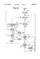
- FIG. 5is a flow diagram of the operating algorithm of the microcontroller in a preferred embodiment.
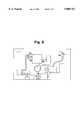
- FIG. 6shows the motion sensor used in a preferred embodiment of the invention.
- the present inventionis described below in reference to an electric space heater. It will be understood, however, that the invention may be applied equally well to other types of heaters in which safety features such as those described will be useful. Thus, in addition to electric space heaters, the invention may be applied to kerosene heaters and to portable heaters.
- a preferred embodiment of the inventioncomprises a space heater 11 including a heating element 12 (such as a radiant coil, an electrical resistance heating element, an electrically-controlled gas or kerosene burner, or other type of heating element) disposed within a housing 13, and a controller module 14.
- the housing 13is made from materials that are sufficiently heat resistant to withstand the heat generated by the heating element 12.
- a controller module 14is associated with one or more display elements, such as light emitting diodes (LEDs) 22, which, as will be discussed below, can be used to display the thermostat setting, provide visual feedback as to the operational mode of the heater 11, or indicate an alarm situation.
- LEDslight emitting diodes
- Other display elementssuch as LCD displays or incandescent lights, may be used.
- a power indicatorsuch as LED 23, also may be provided to indicate that controller module 14 is active and/or to indicate that timer mode (discussed below) has been entered.
- Controller module 14also includes at least one mode selector switch, shown in the drawings as a plurality of mode selector switches 39-1 through 39-5 that are used in various combinations as the ON/OFF selector, thermostat temperature selector, time selector, and motion sensing selector. These features are discussed below in greater detail.
- FIG. 2shows schematically the electrical circuit 30 of the heater 11.
- Circuit 30includes a printed circuit control board 35. Electricity is supplied to the control board 35 from a power source (not shown) through a power cord 36. Electricity also is used to energize the heating element 12 and, optionally, a fan 15 that are connected to the control board 35. The fan 15 is used to force cool air from the inlet over the heating elements and out of the housing 13.
- a temperature-limit switch 16is connected between the power source and heating element 12 to deenergize the heating element 12 by opening the circuit to the heating element 12 and fan 15 if the internal temperature rises above a preset reference temperature. Temperature-limit switch 16 is intended to function primarily as a fail-safe safety feature in the event that other temperature-regulating safety features fail to shut off the heater 11 when necessary.
- FIG. 3shows control board 35 schematically and in greater detail.
- Control board 35includes a first control block 41.
- a transformer T1 in block 41provides a stepped-down AC voltage to a standard bridge rectifier/filter capacitor circuit to convert the AC current from power cord 36 to DC (at, for instance, 9 volts).
- This DC voltagemay be passed through a voltage regulator, such as a 7805, in order to further reduce and regulate the DC voltage.
- the DC voltageis used to supply power to the electronic components.
- the AC current source from power cord 36is used to provide the power necessary to energize the heating element 12 and fan 15. In the embodiment shown in the figures, the DC power source is used to energize a relay RL1 that is connected between the heating element 12 and fan 15 and the AC current source from power cord 36.
- This arrangementallows the control circuitry to energize and deenergize the heating element 12 and fan 15 in response to various operating conditions detected by the heater, as discussed below.
- Solid-state switching devices(such as a triac) of suitable power-handling capability also may be used to control the power delivered to the heating element 12 and fan 15.
- a microcontroller U2as described more fully below, provides a control signal that determines when the relay RL1 is opened or closed in order to energize or deenergize the heating element 12 and the fan 15.
- Control board 35also includes a second control block 51 that includes microcontroller U2, such as a Zilog Z86C30.
- microcontroller U2such as a Zilog Z86C30.
- Other devicessuch as microprocessors, application-specific integrated circuits (ASICs), programmable gate arrays, programmable logic arrays, and even discrete components may be used as alternatives to microcontroller U2.
- ASICsapplication-specific integrated circuits
- One or more heater operating modesare selected by depressing mode selector switches 39 individually or in combination. This action causes microcontroller U2 to execute pertinent portions of a pre-programmed software algorithm discussed below.
- Microcontroller U2in addition to other functions, performs the input and output functions necessary for temperature sampling, monitors signals from the sensor board 37, and a tilt switch 19 that preferably is included in the heater 11 to detect when the heater is not standing in a proper operating position.
- Microcontroller U2also preferably is interfaced to one or more alarm devices, which may include a buzzer 34 that emits different sounds in response to alarm situations (such as tip-over, motion near the heater, or overheat) or a visual alarm means such as LEDs 22, or both.
- the alarm devicealso may provide aural feedback to indicate when various heater modes are set, or when mode selector switches 39 are depressed. For example, in the embodiment shown, tilt switch 19 activates if the heater 11 tilts beyond a predetermined angle, which in turn signals the microcontroller U2 to deenergize the heating element 12 and fan 15 while sounding the buzzer 34.
- Microcontroller U2also is interfaced to the LED array 22 that preferably illuminates in different patterns in accordance with the timer setting, thermostat setting, motion-sensing setting, and alarm situations.
- a limited number of LEDsmay be used to provide a visual display of temperature or other conditions of the heater, and each LED duty-cycled at different rates to provide a display unique to a particular condition. For example, if each LED may be duty-cycled at three different rates, each LED in the array may appear at one of three different levels of brightness (or off), thereby permitting the LED array 22 to indicate many different settings and patterns.
- Control board 35also includes analog-to-digital converter (ADC) circuitry shown as ADC control block 71.
- ADCanalog-to-digital converter
- the ADC 71is used to convert analog voltage levels into digital numbers for use by microcontroller U2. Any commercially available discrete ADC, such as an ADC0804 also may be used for this purpose.
- the ADC 71allows microcontroller U2 to interpret and respond to data collected from attached sensors.
- Control board 35is connected to a first thermistor 17 and a sensor board 37.
- Thermistors 17 and 38like other thermistors commonly found in industry, have a resistance that varies inversely with temperature.
- Thermistor 17is interfaced to the ADC 71 to provide to microcontroller U2 temperature information about the space near the heating element 12 where thermistor 17 is located; this temperature will be referred herein as the "internal temperature" of the heater.
- Temperature sensingalternatively may be accomplished using other commercially available devices, such as thermocouples, solid-state temperature sensors and RTDs.
- ADC 71Preferably also interfaced to ADC 71 is a circuit that monitors the AC voltage that is impressed upon the heating element 12 and fan 15 when relay RL1 is closed. This circuit produces a DC voltage that is proportional to the average of the AC voltage supplied to the heating element 12. Because the wattage of the electric heating element 12 is related to the voltage across it, this circuit provides the microcontroller U2 with a means of determining whether a rise in the temperature sensed by thermistor 17 is the result of a corresponding rise in the voltage supplied to heating element 12, rather than the result of abnormal conditions such as a blockage in front of the heater or an inoperative fan. Microcontroller U2 analyzes the average AC readings and, if a sudden rise in voltage is detected, ignores the corresponding rise in temperature sensed by thermistor 17.
- a second thermistor 38is located within the heater 11 (preferably on sensor board 37) to provide information relating to the ambient temperature of the heater's environment, and thus should not be in a location significantly affected by heat generated by heating means 12. Like first thermistor 17, second thermistor 38 also is interfaced to the ADC 71, so that ambient temperature information is provided to microcontroller U2.
- microcontroller U2will deenergize the heating element 12 if (i) the internal temperature sensed by thermistor 17 increases at an excessive rate, such as a rise of more than 10° F. in any 10 second period, (ii) the internal temperature exceeds the ambient temperature by an excessive amount such as 145° F., or (iii) the internal temperature exceeds an absolute temperature such as 250° F.
- the values against which the internal temperature is compared using microcontroller U2are selected to provide safe heating and are used to detect an abnormal heating condition such as a blocked outlet or inoperable fan. Of course, it is not necessary to program microcontroller U2 to detect all of these abnormal conditions, and the selection of which conditions will be detected in a given heater is at the discretion of the designer.
- microcontroller U2When the heating element 12 is deenergized in response to an abnormal heating condition in the embodiment depicted in the drawings, microcontroller U2 will direct the LED array 22 to flash on and off, and the buzzer 34 will sound loudly. This state is known as "manual reset mode," because it preferably requires the user to press one or more of the mode selector switches 39-1 through 39-5 to deactivate the visual and aural alarm. The heater 11 then may be reactivated as desired.
- sensor board 37preferably also includes a motion detector means that signals the microcontroller U2 if motion is detected too close to the heater 11.
- a motion detector meansthat signals the microcontroller U2 if motion is detected too close to the heater 11.
- One or more motion detector meansmay be employed so that motion is detected on all sides of the heater, or in only selected directions (such as in front of the heater).
- the preferred motion detector meansis commonly found in industry, and is referred to as a "field disturbance sensor.”
- This type of sensoremploys a microwave oscillator of which the resonant frequency is affected by objects of sufficient mass and velocity moving in the vicinity of the oscillator. The effect an object has on the oscillator is directly proportional to the object's mass and speed, and inversely proportional to the object's distance from the oscillator.
- the motion detector meansincludes an oscillator embodied in circuit traces that preferably are etched on one side of a printed circuit board as depicted in FIG. 6.
- the particular circuit shownhas been empirically designed to detect objects of average masses moving at average speeds. As a result, the circuit is able to detect, for such objects, the proximity of the object to the heater.
- the motion detector found on sensor board 37preferably includes a sensor block 91 that functions as a "far zone” detector and as a "near zone” detector to roughly correspond to the relative distances of objects from the heater.
- the motion detector found on sensor board 37preferably includes a sensor block 91 that determines the magnitude of the frequency variation due to the detected motion which is then classified as either a "near zone” disturbance (large magnitude) or "far zone” disturbance (small magnitude).
- Near zonedisturbances are generally small, relatively fast moving objects near the heater or large, slower moving objects farther from the heater.
- Flu zonedisturbances are all other detected motion which results in a frequency variation below the minimum value for it to be classified as a "near zone” disturbance, and meeting a minimum threshold for detection. Certain motion may be outside the thresholds of detection of a particular motion sensing means, which should be set as described above.
- the LED array 22illuminates in a sweeping pattern when motion sensing is enabled. If the sensor detects motion of predefined characteristics (with respect to the magnitude of disturbance in the case of a field disturbance-type motion sensor, or in the case of predefined distances, directions, and/or speeds in other cases) as a far zone disturbance, the sweep rate of the LED array 22 increases and the buzzer 34 beeps softly in warning. If further motion is not detected, buzzer 34 stops beeping and LED array 22 returns to the "normal" sweep rate. If further motion is detected, and is of a magnitude recognized by microcontroller U2 as a "near zone” disturbance, an alarm signal is generated, e.g., an L.E.D.
- an alarm signalis generated, e.g., an L.E.D.
- a timer functionalso may be provided to automatically activate or deactivate the heater 11 after a selected time interval.
- This timer functionmay be performed by microcontroller U2 using an oscillator X1 that is present within the microcontroller, or by other time-measuring means (such as an RC timing circuit, or mechanical timer).
- Mode selector switch 39-5is used to enter delay times into microcontroller U2, after which the heater 11 becomes active or inactive. In the depicted embodiment, when timer set mode is active, power LED 23 flashes on and off, and the LED array 22 indicates the desired amount of delay time.
- mode selector switch 39-5must be pressed when unit is on. This causes power LED 23 to flash on and off, indicating the microcontroller U2 is in timer set mode. In addition, the LED array 22 illuminates to indicate an off time of one time increment. Time increments can be any value deemed desirable (such as 1 hour or 2 hours per increment). Each subsequent press of mode selector switch 39-5 causes the buzzer 34 to "pip" and the next LED in the LED array 22 to illuminate, indicating an additional increment of off time. When all LEDs of LED array 22 are illuminated, a maximum off time is indicated.
- mode selector switch 39-5turns off all the LEDs in LED array 22, indicating no off time. Subsequent presses of mode selector switch 39-5 repeat the sequence. If mode selector switch 39-5 is not pressed within a certain time, the current setting is accepted and LED array 22 returns to its previous state. If a non-zero off time is set, power LED 23 continues to flash indicating an active timer setting. If no off time was set, power LED 23 returns to its previous state. The heater 11 will continue to operate normally until the off time has passed, at which point the heater 11 will turn off.
- mode selector switch 39-5must be pressed and held for a certain time while the heater 11 is off.
- Power LED 23flashes on and off to indicate timer set mode, the LED array 22 illuminates, and on time is set in the same manner as off time. If mode selector switch 39-5 is not pressed within a certain time, buzzer 34 sounds a "pip" and the current setting is accepted. If a non-zero on time is set, power LED 23 flashes on and off indicating an active timer setting and LED array 22 continues to display the on time setting, extinguishing LEDs in LED array 22 as the on time passes. After the on time has elapsed, the heater 11 will turn on and motion sensing is automatically enabled. If no on time is set, the power LED 23 and all LEDs in LED array 22 turn off, and the heater 11 remains off.
- microcontroller U2is preprogrammed with an operating algorithm that processes signals from sensor board 37 and control board 35, monitors the mode selector switches 39-1 through 39-5, and controls the LED array 22 and power LED 23 to form the user interface, and controls the various functional modes of the heater.
- FIG. 5the operating sequence of a preferred program now will be described. The sequence of FIG. 5 is not considered important to the invention, so long as each of the desired functions is performed. (It also should be understood that one or more of the steps described in the algorithm may be performed in hardware, rather than in software, without departing from the invention. Likewise, one or more of the functions, such as the tilt switch, may be excluded from a particular embodiment without departing from the invention.)
- microcontroller U2first checks the status of the tilt switch 19 and the temperature limit switch 16. If it detects that the heater 11 is tilted beyond a predetermined amount or the temperature limit switch 16 has opened, then the heating element 12 and fan 15 are deenergized and the heater 11 enters the manual reset mode 220. If the heater 11 is not tilted beyond a predetermined amount and the temperature limit switch 16 has not opened, then microcontroller U2 checks to see whether the heater 11 has been turned on or off in block 230. If the heater 11 has been turned off, the heating element 12 and fan 15 are deenergized, microcontroller U2 checks to see if the timer mode is set to turn the heater 11 on automatically (in blocks 240, 243, 245, and 247).
- timer modeIf timer mode is active, the heater 11 will turn on after the desired delay and automatically enable motion sensing. If the heater 11 is on, microcontroller U2 checks to see if timer mode is set to turn the heater 11 off automatically (in blocks 250, 253, and 257). If timer mode is set, then the heater 11 will turn off and deenergize the heating element 12 and fan 15 after the desired delay.
- microcontroller U2checks to see if motion sensing is enabled, in block 260. If motion sensing is enabled, microcontroller U2 checks input signals from the motion detector means. If the far zone detector detects an abnormal condition (in block 263), microcontroller U2 triggers an alarm by illuminating LEDs 22 and sounding buzzer 34. Microcontroller U2 then checks whether the near zone detector detects an abnormal condition (in block 267). If so, microcontroller U2 waits for a preset time to detect whether the pause button 39-1 is pressed and held for the predetermined period (as shown in block 290), and if so, microcontroller U2 cancels the alarm, and waits for controller buttons 39-1 to 39-5 to cease being adjusted.
- motion sensingis automatically restarted after a period of time to allow the operator to leave the immediate vicinity of the heater. If mode selector switches are not operated in the preset time, heating element 12 and fan 15 are deenergized, and the heater 11 enters manual reset mode. If the near zone motion is detected and no action is taken to pause or otherwise disable the motion sensor or heater, the heater enters manual reset mode 220.
- Microcontroller U2also checks whether the heating element 12 is currently energized in block 270. If heating element 12 is energized, microcontroller U2 checks (in block 275) the rate of internal temperature rise as sensed by first thermistor 17, along with the absolute temperature sensed by thermistor 17, and the difference in the temperature sensed by thermistor 17 and the ambient room temperature sensed by second thermistor 38. These values are compared by microcontroller U2 with predetermined safe values for each of the conditions, and if any abnormal condition is detected, heating element 12 and fan 15 are deenergized, an alarm is triggered, and the heater 11 enters manual reset mode.
- mode selector switch, 39-3 or 39-2is pressed to raise or to lower the setpoint, respectively.
- Buzzer 34sounds to indicate the change, and the LED array 22 illuminates to show the current thermostat setting.
- microcontroller U2checks whether heat is needed in block 280 by comparing the ambient room temperature sensed by thermistor 38 to the current setpoint. If heating is needed, as shown by blocks 283 and 287, heating element 12 and fan 15 are energized or remain energized; if heat is not needed, the heating element and/or fan are deenergized.
- the operating program of microcontroller U2repeats the operating algorithm from the start, beginning with the check of the tilt switch 19 and the temperature limit switch 16.
Landscapes
- Engineering & Computer Science (AREA)
- Physics & Mathematics (AREA)
- Thermal Sciences (AREA)
- Chemical & Material Sciences (AREA)
- Combustion & Propulsion (AREA)
- Mechanical Engineering (AREA)
- General Engineering & Computer Science (AREA)
- Computer Hardware Design (AREA)
- General Physics & Mathematics (AREA)
- Automation & Control Theory (AREA)
- Control Of Resistance Heating (AREA)
Abstract
Description
Claims (36)
Priority Applications (1)
| Application Number | Priority Date | Filing Date | Title |
|---|---|---|---|
| US08/585,098US5805767A (en) | 1996-01-16 | 1996-01-16 | Electronically-controlled heater |
Applications Claiming Priority (1)
| Application Number | Priority Date | Filing Date | Title |
|---|---|---|---|
| US08/585,098US5805767A (en) | 1996-01-16 | 1996-01-16 | Electronically-controlled heater |
Publications (1)
| Publication Number | Publication Date |
|---|---|
| US5805767Atrue US5805767A (en) | 1998-09-08 |
Family
ID=24340036
Family Applications (1)
| Application Number | Title | Priority Date | Filing Date |
|---|---|---|---|
| US08/585,098Expired - Fee RelatedUS5805767A (en) | 1996-01-16 | 1996-01-16 | Electronically-controlled heater |
Country Status (1)
| Country | Link |
|---|---|
| US (1) | US5805767A (en) |
Cited By (63)
| Publication number | Priority date | Publication date | Assignee | Title |
|---|---|---|---|---|
| US6013901A (en)* | 1997-09-18 | 2000-01-11 | Lavoie; Manon | Portable heated cup with motion sensor and timer |
| US6012538A (en)* | 1996-09-26 | 2000-01-11 | Mitsubishi Heavy Industries, Ltd. | Driving unit for an electric motor driven bicycle |
| USD420113S (en)* | 1998-12-11 | 2000-02-01 | Holmes Products, Corp. | Heater |
| USD424671S (en)* | 1998-08-14 | 2000-05-09 | Adobeair, Inc. | Portable space heater |
| US6091888A (en)* | 1995-05-15 | 2000-07-18 | Honeywell Consumer Products, Inc. | Portable environmental conditioning device with presence detector responsive shutoff |
| USD431640S (en)* | 1998-12-04 | 2000-10-03 | Chern-Bao Rong | Electric heater |
| US6167193A (en)* | 1999-11-26 | 2000-12-26 | Honeywell Inc. | Portable electric heater with digital display |
| US6169850B1 (en) | 1998-02-24 | 2001-01-02 | Menassa Cherif | Air heating device |
| US6712290B2 (en)* | 2002-07-17 | 2004-03-30 | Yen Sun Technology Corp. | Skin cleaner |
| US6748163B2 (en) | 2001-07-19 | 2004-06-08 | King Electrical Manufacturing Company | Electric heater with dual overheat limits |
| USD495795S1 (en) | 2002-06-10 | 2004-09-07 | Hp Intellectual Corp. | Heater |
| US20050109764A1 (en)* | 2003-11-25 | 2005-05-26 | National Environmental Products, Ltd. | Forced-air heater control system and method |
| US20050236388A1 (en)* | 2004-04-08 | 2005-10-27 | Maytag Corporation | Control system for cooking appliance employing convection and radiant cooking |
| EP1653165A1 (en)* | 2004-10-29 | 2006-05-03 | Osram Sylvania Inc. | Heater with burnout protection |
| US20060283405A1 (en)* | 2005-05-20 | 2006-12-21 | Hsien-Lung Chou | Atomizer used for facial treatment |
| US20070046107A1 (en)* | 2005-08-29 | 2007-03-01 | Sunbeam Products, Inc. | Portable electrical applicance with object sensing assembly |
| US7190887B1 (en) | 2005-03-28 | 2007-03-13 | Compton Stephan S | Portable thermal-stratifying space heater and powerplant package |
| US20070077042A1 (en)* | 2005-09-22 | 2007-04-05 | Sunbeam Products, Inc. | Portable electrical appliance with diagnostic system |
| US20070154193A1 (en)* | 2004-01-07 | 2007-07-05 | C-Tech Innovation Limited | Liquid heating apparatus and method |
| US20080018445A1 (en)* | 2004-12-24 | 2008-01-24 | The Yokohama Rubber Co., Ltd | Vehicle Abnormality Detection Method and Device Thereof and Sensor Unit Thereof |
| US7347669B1 (en) | 2005-02-25 | 2008-03-25 | Patrick Jeffrey D | Sensor-actuated power fan |
| US20090023105A1 (en)* | 2007-07-19 | 2009-01-22 | Chiaphua Winport International Ltd. | System for controlling gas supply to a gas burner of a patio heater |
| US20090214194A1 (en)* | 2008-02-21 | 2009-08-27 | Honor Tone, Ltd. | Outdoor heater |
| US20090304370A1 (en)* | 2008-06-09 | 2009-12-10 | Alain Dupuis | Device and method for controlling infrared lamp ovens |
| GB2461540A (en)* | 2008-07-02 | 2010-01-06 | Basic Holdings | A heater including an independent visual indicating means |
| US20100000714A1 (en)* | 2005-10-14 | 2010-01-07 | Yousef Daneshvar | Modern Korsi and methods |
| US20100027583A1 (en)* | 2007-02-06 | 2010-02-04 | Thorn Security Limited | Detector |
| US20100071258A1 (en)* | 2008-09-25 | 2010-03-25 | Christopher Molnar | Insect eradication system and method |
| US20100140062A1 (en)* | 2008-12-09 | 2010-06-10 | Stmicroelectronics, Inc. | Protective circuit for an apparatus |
| US20110163083A1 (en)* | 2008-09-09 | 2011-07-07 | Kevin Lin | Heating control device and method thereof |
| US20110205071A1 (en)* | 2010-02-24 | 2011-08-25 | Sony Corporation | Electronic apparatus and method of controlling electronic apparatus |
| US20120097662A1 (en)* | 2010-10-22 | 2012-04-26 | Ewell Jr Robert C | Device and method for monitoring a heating appliance |
| US20120103963A1 (en)* | 2009-03-20 | 2012-05-03 | Mensa Heating Aps | Heating apparatus for arranging under a table |
| USD671199S1 (en)* | 2012-05-09 | 2012-11-20 | Donald William Bryce | Heating apparatus |
| US8564158B2 (en) | 2010-04-21 | 2013-10-22 | Electrolux Home Products, Inc. | Appliance having user detection functionality for controlling operation thereof |
| US20130294477A1 (en)* | 2011-10-19 | 2013-11-07 | John Rankin | Method for Indirect Food Temperature Measurement |
| USD694380S1 (en)* | 2012-06-08 | 2013-11-26 | Twin-Star International, Inc. | Heater |
| US20140005834A1 (en)* | 2012-06-13 | 2014-01-02 | Ronald J. Hoffman | Device for Controlling a Coffee Maker |
| US8921743B2 (en) | 2010-10-22 | 2014-12-30 | Stovminder, Llc | Device and method for monitoring a heating appliance |
| US20150096734A1 (en)* | 2013-10-09 | 2015-04-09 | Ming-Chien Chang | Temperature control device |
| CN104697163A (en)* | 2015-03-04 | 2015-06-10 | 慈溪市沣锐电器有限公司 | Waterproof fan heater |
| GB2525439A (en)* | 2014-04-25 | 2015-10-28 | Tom Chandley Ltd | Monitor |
| CN105240905A (en)* | 2015-10-28 | 2016-01-13 | 桂林新艺制冷设备有限责任公司 | Safe warmer |
| CN105240904A (en)* | 2015-10-28 | 2016-01-13 | 桂林新艺制冷设备有限责任公司 | Fireproof heater |
| US20160021703A1 (en)* | 2013-03-06 | 2016-01-21 | Basic Holdings | Heating appliance |
| US9279599B2 (en)* | 2013-04-07 | 2016-03-08 | Lite-On Technology Corporation | Heating unit and heating system using the same |
| US9739489B2 (en) | 2010-10-22 | 2017-08-22 | Stovminder, Llc | Monitoring system and method for monitoring a room |
| US20170343240A1 (en)* | 2016-05-30 | 2017-11-30 | Steven Yu | Combination cooling and heating fan structure |
| CN107421130A (en)* | 2017-09-06 | 2017-12-01 | 泰州钊阳冷暖风机制造有限公司 | A kind of warm-air drier control intelligence instrument |
| JP2018190020A (en)* | 2017-04-28 | 2018-11-29 | アズビル株式会社 | Temperature Controller |
| JP2021021526A (en)* | 2019-07-26 | 2021-02-18 | 株式会社コロナ | Heating machine |
| US20210172651A1 (en)* | 2019-12-06 | 2021-06-10 | Matthew Alfred CROWE | Electric space heater |
| US11098268B2 (en)* | 2016-12-08 | 2021-08-24 | Jaeyun Jang | Device for manufacturing scented candle |
| US20210302068A1 (en)* | 2020-03-31 | 2021-09-30 | World & Main (Cranbury) LLC | PTC Heater with Energy Save Function |
| US20210302065A1 (en)* | 2020-03-31 | 2021-09-30 | World & Main (Cranbury) LLC | Segmented PTC Heating Element Array |
| US11181402B2 (en)* | 2011-11-11 | 2021-11-23 | Sony Group Corporation | System and method for the assisted calibration of sensors distributed across different devices |
| CN113797983A (en)* | 2021-09-13 | 2021-12-17 | 江苏拓米洛环境试验设备有限公司 | Door frame heating method, device and system of test box |
| USD972096S1 (en)* | 2022-07-29 | 2022-12-06 | JozieV, Inc. | Enhanced heating system |
| US20230028124A1 (en)* | 2019-08-05 | 2023-01-26 | The Merchant Of Tennis, Inc. | Portable heater with ceramic substrate |
| US20230097894A1 (en)* | 2021-09-24 | 2023-03-30 | Shanghai Kohler Electronics, Ltd. | Driving part of warm air heater and warm air heater |
| USD1005461S1 (en)* | 2022-08-03 | 2023-11-21 | Ningbo Youmin Electric Appliance Co., Ltd. | Heater |
| US12066192B2 (en) | 2018-11-29 | 2024-08-20 | Broan-Nutone Llc | Smart indoor air venting system |
| US20240377103A1 (en)* | 2023-05-12 | 2024-11-14 | Mitchell J. Francis | Portable electric heater |
Citations (37)
| Publication number | Priority date | Publication date | Assignee | Title |
|---|---|---|---|---|
| US2963627A (en)* | 1957-12-03 | 1960-12-06 | American Brake Shoe Co | Electronic guard |
| US3450862A (en)* | 1965-12-02 | 1969-06-17 | Edward M Kralovec Jr | Control of electric heat |
| US3560970A (en)* | 1964-04-30 | 1971-02-02 | Hitachi Ltd | Obstacle detector utilizing waveguide |
| US3594546A (en)* | 1968-09-13 | 1971-07-20 | Tronapplics Ltd | Air temperature control apparatus |
| US3916152A (en)* | 1972-05-31 | 1975-10-28 | Union Carbide Corp | Temperature control system for a centrifugal-type chemistry analyzer |
| DE3011678A1 (en)* | 1980-03-24 | 1981-10-01 | Manfred Dipl.-Volksw. 1000 Berlin Hirche | Automatic differential temp. control for room heating - uses movement sensors to raise maintained room temp. level when room is in use |
| JPS5749094A (en)* | 1980-09-08 | 1982-03-20 | Hitachi Ltd | Electric-fan controlling apparatus |
| DE3147085A1 (en)* | 1981-11-27 | 1983-06-09 | Bernd Dipl.-Ing. Dr. 4410 Warendorf Heiland | Device for energy saving, in particular in heated or air-conditioned rooms |
| JPS59209399A (en)* | 1983-05-13 | 1984-11-27 | 松下電器産業株式会社 | Temperature controller of clothing dryer |
| JPS60186630A (en)* | 1984-03-05 | 1985-09-24 | Nippon Denso Co Ltd | Hot air space heater |
| US4633062A (en)* | 1984-10-30 | 1986-12-30 | Matsushita Electric Industrial Co., Ltd. | Electric blanket |
| US4661720A (en)* | 1986-06-09 | 1987-04-28 | The Watt Watcher, Inc. | Occupancy sensor |
| JPS62202945A (en)* | 1986-02-28 | 1987-09-07 | Matsushita Electric Ind Co Ltd | Controller for combustion type warm air heater |
| JPS63135713A (en)* | 1986-11-27 | 1988-06-08 | Matsushita Electric Ind Co Ltd | hot air heater |
| US4755653A (en)* | 1987-01-05 | 1988-07-05 | Arvin Industries, Inc. | Heater with alert indicator |
| US4775913A (en)* | 1987-09-02 | 1988-10-04 | Ekblad Carl A | Safety shutoff device for a stove |
| JPS63284611A (en)* | 1987-05-15 | 1988-11-21 | Matsushita Electric Works Ltd | Environmental temperature controller |
| US4827627A (en)* | 1988-02-22 | 1989-05-09 | American Dryer Corporation | Apparatus and method for controlling a drying cycle of a clothes dryer |
| US4906818A (en)* | 1988-06-14 | 1990-03-06 | Toastmaster, Inc. | Heater safety mechanism |
| JPH02197727A (en)* | 1989-01-26 | 1990-08-06 | Matsushita Electric Works Ltd | Air cleaner with hot-air blowing function |
| JPH0320565A (en)* | 1989-06-16 | 1991-01-29 | Sanyo Electric Co Ltd | Controller for hot air heater |
| US5007103A (en)* | 1988-10-21 | 1991-04-09 | Rival Manufacturing Company | Automatic shut-off and alarm for electric heater |
| US5083011A (en)* | 1990-11-27 | 1992-01-21 | Coppus Engineering Corporation | Air heater with safety control circuit |
| JPH0464396A (en)* | 1990-07-02 | 1992-02-28 | Sanyo Electric Co Ltd | Controlling device for clothing drier |
| JPH04256798A (en)* | 1991-02-08 | 1992-09-11 | Matsushita Electric Ind Co Ltd | clothes dryer |
| US5163234A (en)* | 1989-03-15 | 1992-11-17 | Inax Corporation | Hand drier control apparatus |
| JPH05106853A (en)* | 1991-08-15 | 1993-04-27 | Mitsubishi Electric Home Appliance Co Ltd | Electric heater |
| US5245691A (en)* | 1989-07-03 | 1993-09-14 | Holmes Products Corp. | Electric heater circuit |
| US5278936A (en)* | 1991-12-23 | 1994-01-11 | Steve Shao | Thermostatically controlled portable electric space heater with automatic temperature setback for energy saving |
| US5281961A (en)* | 1990-07-06 | 1994-01-25 | Novitas, Inc. | Motion detection sensor with computer interface |
| US5291667A (en)* | 1990-04-26 | 1994-03-08 | White Consolidated Industries, Inc. | Electronic control of clothes dryer |
| US5295531A (en)* | 1991-09-02 | 1994-03-22 | Sanyo Electric Co., Ltd. | Air conditioner with outside air introduction path |
| JPH06142009A (en)* | 1992-11-12 | 1994-05-24 | Sekisui Chem Co Ltd | Heater and sanitary room with the heater |
| US5318224A (en)* | 1992-05-04 | 1994-06-07 | David Darby | Method and apparatus for heating and cooling control |
| US5345471A (en)* | 1993-04-12 | 1994-09-06 | The Regents Of The University Of California | Ultra-wideband receiver |
| US5361070A (en)* | 1993-04-12 | 1994-11-01 | Regents Of The University Of California | Ultra-wideband radar motion sensor |
| US5380985A (en)* | 1994-01-06 | 1995-01-10 | Graham; Larry J. | Presence delector for controlling an electric range |
- 1996
- 1996-01-16USUS08/585,098patent/US5805767A/ennot_activeExpired - Fee Related
Patent Citations (39)
| Publication number | Priority date | Publication date | Assignee | Title |
|---|---|---|---|---|
| US2963627A (en)* | 1957-12-03 | 1960-12-06 | American Brake Shoe Co | Electronic guard |
| US3560970A (en)* | 1964-04-30 | 1971-02-02 | Hitachi Ltd | Obstacle detector utilizing waveguide |
| US3450862A (en)* | 1965-12-02 | 1969-06-17 | Edward M Kralovec Jr | Control of electric heat |
| US3594546A (en)* | 1968-09-13 | 1971-07-20 | Tronapplics Ltd | Air temperature control apparatus |
| US3916152A (en)* | 1972-05-31 | 1975-10-28 | Union Carbide Corp | Temperature control system for a centrifugal-type chemistry analyzer |
| DE3011678A1 (en)* | 1980-03-24 | 1981-10-01 | Manfred Dipl.-Volksw. 1000 Berlin Hirche | Automatic differential temp. control for room heating - uses movement sensors to raise maintained room temp. level when room is in use |
| JPS5749094A (en)* | 1980-09-08 | 1982-03-20 | Hitachi Ltd | Electric-fan controlling apparatus |
| DE3147085A1 (en)* | 1981-11-27 | 1983-06-09 | Bernd Dipl.-Ing. Dr. 4410 Warendorf Heiland | Device for energy saving, in particular in heated or air-conditioned rooms |
| JPS59209399A (en)* | 1983-05-13 | 1984-11-27 | 松下電器産業株式会社 | Temperature controller of clothing dryer |
| JPS60186630A (en)* | 1984-03-05 | 1985-09-24 | Nippon Denso Co Ltd | Hot air space heater |
| US4633062A (en)* | 1984-10-30 | 1986-12-30 | Matsushita Electric Industrial Co., Ltd. | Electric blanket |
| JPS62202945A (en)* | 1986-02-28 | 1987-09-07 | Matsushita Electric Ind Co Ltd | Controller for combustion type warm air heater |
| US4661720A (en)* | 1986-06-09 | 1987-04-28 | The Watt Watcher, Inc. | Occupancy sensor |
| JPS63135713A (en)* | 1986-11-27 | 1988-06-08 | Matsushita Electric Ind Co Ltd | hot air heater |
| US4755653A (en)* | 1987-01-05 | 1988-07-05 | Arvin Industries, Inc. | Heater with alert indicator |
| US4755653B1 (en)* | 1987-01-05 | 1990-11-06 | Arvin Ind Inc | |
| JPS63284611A (en)* | 1987-05-15 | 1988-11-21 | Matsushita Electric Works Ltd | Environmental temperature controller |
| US4775913A (en)* | 1987-09-02 | 1988-10-04 | Ekblad Carl A | Safety shutoff device for a stove |
| US4827627A (en)* | 1988-02-22 | 1989-05-09 | American Dryer Corporation | Apparatus and method for controlling a drying cycle of a clothes dryer |
| US4906818A (en)* | 1988-06-14 | 1990-03-06 | Toastmaster, Inc. | Heater safety mechanism |
| US5007103A (en)* | 1988-10-21 | 1991-04-09 | Rival Manufacturing Company | Automatic shut-off and alarm for electric heater |
| JPH02197727A (en)* | 1989-01-26 | 1990-08-06 | Matsushita Electric Works Ltd | Air cleaner with hot-air blowing function |
| US5163234A (en)* | 1989-03-15 | 1992-11-17 | Inax Corporation | Hand drier control apparatus |
| JPH0320565A (en)* | 1989-06-16 | 1991-01-29 | Sanyo Electric Co Ltd | Controller for hot air heater |
| US5245691A (en)* | 1989-07-03 | 1993-09-14 | Holmes Products Corp. | Electric heater circuit |
| US5291667A (en)* | 1990-04-26 | 1994-03-08 | White Consolidated Industries, Inc. | Electronic control of clothes dryer |
| JPH0464396A (en)* | 1990-07-02 | 1992-02-28 | Sanyo Electric Co Ltd | Controlling device for clothing drier |
| US5281961A (en)* | 1990-07-06 | 1994-01-25 | Novitas, Inc. | Motion detection sensor with computer interface |
| US5083011A (en)* | 1990-11-27 | 1992-01-21 | Coppus Engineering Corporation | Air heater with safety control circuit |
| JPH04256798A (en)* | 1991-02-08 | 1992-09-11 | Matsushita Electric Ind Co Ltd | clothes dryer |
| JPH05106853A (en)* | 1991-08-15 | 1993-04-27 | Mitsubishi Electric Home Appliance Co Ltd | Electric heater |
| US5295531A (en)* | 1991-09-02 | 1994-03-22 | Sanyo Electric Co., Ltd. | Air conditioner with outside air introduction path |
| US5278936A (en)* | 1991-12-23 | 1994-01-11 | Steve Shao | Thermostatically controlled portable electric space heater with automatic temperature setback for energy saving |
| US5318224A (en)* | 1992-05-04 | 1994-06-07 | David Darby | Method and apparatus for heating and cooling control |
| JPH06142009A (en)* | 1992-11-12 | 1994-05-24 | Sekisui Chem Co Ltd | Heater and sanitary room with the heater |
| US5345471A (en)* | 1993-04-12 | 1994-09-06 | The Regents Of The University Of California | Ultra-wideband receiver |
| US5361070A (en)* | 1993-04-12 | 1994-11-01 | Regents Of The University Of California | Ultra-wideband radar motion sensor |
| US5361070B1 (en)* | 1993-04-12 | 2000-05-16 | Univ California | Ultra-wideband radar motion sensor |
| US5380985A (en)* | 1994-01-06 | 1995-01-10 | Graham; Larry J. | Presence delector for controlling an electric range |
Cited By (92)
| Publication number | Priority date | Publication date | Assignee | Title |
|---|---|---|---|---|
| US6091888A (en)* | 1995-05-15 | 2000-07-18 | Honeywell Consumer Products, Inc. | Portable environmental conditioning device with presence detector responsive shutoff |
| US6012538A (en)* | 1996-09-26 | 2000-01-11 | Mitsubishi Heavy Industries, Ltd. | Driving unit for an electric motor driven bicycle |
| US6013901A (en)* | 1997-09-18 | 2000-01-11 | Lavoie; Manon | Portable heated cup with motion sensor and timer |
| US6169850B1 (en) | 1998-02-24 | 2001-01-02 | Menassa Cherif | Air heating device |
| USD424671S (en)* | 1998-08-14 | 2000-05-09 | Adobeair, Inc. | Portable space heater |
| USD431640S (en)* | 1998-12-04 | 2000-10-03 | Chern-Bao Rong | Electric heater |
| USD420113S (en)* | 1998-12-11 | 2000-02-01 | Holmes Products, Corp. | Heater |
| US6167193A (en)* | 1999-11-26 | 2000-12-26 | Honeywell Inc. | Portable electric heater with digital display |
| WO2001039550A1 (en)* | 1999-11-26 | 2001-05-31 | Honeywell Inc. | Portable electric heater with digital display |
| US6748163B2 (en) | 2001-07-19 | 2004-06-08 | King Electrical Manufacturing Company | Electric heater with dual overheat limits |
| USD495795S1 (en) | 2002-06-10 | 2004-09-07 | Hp Intellectual Corp. | Heater |
| US6712290B2 (en)* | 2002-07-17 | 2004-03-30 | Yen Sun Technology Corp. | Skin cleaner |
| US20050109764A1 (en)* | 2003-11-25 | 2005-05-26 | National Environmental Products, Ltd. | Forced-air heater control system and method |
| US20060006167A1 (en)* | 2003-11-25 | 2006-01-12 | Zev Kopel | Forced-air heater control system and method |
| US7012223B2 (en) | 2003-11-25 | 2006-03-14 | National Environmental Products, Ltd. | Forced-air heater control system and method |
| US7119308B2 (en) | 2003-11-25 | 2006-10-10 | Zev Kopel | Forced-air heater control system and method |
| US7742689B2 (en)* | 2004-01-07 | 2010-06-22 | C-Tech Innovation Limited | Liquid heating apparatus and method |
| US20070154193A1 (en)* | 2004-01-07 | 2007-07-05 | C-Tech Innovation Limited | Liquid heating apparatus and method |
| US20050236388A1 (en)* | 2004-04-08 | 2005-10-27 | Maytag Corporation | Control system for cooking appliance employing convection and radiant cooking |
| US7109447B2 (en)* | 2004-04-08 | 2006-09-19 | Maytag Corporation | Control system for cooking appliance employing convection and radiant cooking |
| EP1653165A1 (en)* | 2004-10-29 | 2006-05-03 | Osram Sylvania Inc. | Heater with burnout protection |
| US7180039B2 (en) | 2004-10-29 | 2007-02-20 | Osram Sylvania Inc. | Heater with burnout protection |
| US20060091132A1 (en)* | 2004-10-29 | 2006-05-04 | Osram Sylvania Inc. | Heater with Burnout Protection |
| US8026802B2 (en)* | 2004-12-24 | 2011-09-27 | The Yokohama Rubber Co., Ltd. | Vehicle abnormality detection method and device thereof and sensor unit thereof |
| US20080018445A1 (en)* | 2004-12-24 | 2008-01-24 | The Yokohama Rubber Co., Ltd | Vehicle Abnormality Detection Method and Device Thereof and Sensor Unit Thereof |
| US7347669B1 (en) | 2005-02-25 | 2008-03-25 | Patrick Jeffrey D | Sensor-actuated power fan |
| US7190887B1 (en) | 2005-03-28 | 2007-03-13 | Compton Stephan S | Portable thermal-stratifying space heater and powerplant package |
| US20060283405A1 (en)* | 2005-05-20 | 2006-12-21 | Hsien-Lung Chou | Atomizer used for facial treatment |
| WO2007027637A3 (en)* | 2005-08-29 | 2008-11-06 | Sunbeam Products Inc | Portable electrical appliance with object sensing assembly |
| US7573158B2 (en) | 2005-08-29 | 2009-08-11 | Sunbeam Products, Inc. | Portable electrical appliance with object sensing assembly |
| US20070046107A1 (en)* | 2005-08-29 | 2007-03-01 | Sunbeam Products, Inc. | Portable electrical applicance with object sensing assembly |
| US20070077042A1 (en)* | 2005-09-22 | 2007-04-05 | Sunbeam Products, Inc. | Portable electrical appliance with diagnostic system |
| EP1926405A4 (en)* | 2005-09-22 | 2008-12-31 | Sunbeam Products Inc | Portable electrical appliance with diagnostic system |
| US8822885B2 (en)* | 2005-10-14 | 2014-09-02 | Yousef Daneshvar | Modern Korsi and methods |
| US20100000714A1 (en)* | 2005-10-14 | 2010-01-07 | Yousef Daneshvar | Modern Korsi and methods |
| US9134180B2 (en)* | 2007-02-06 | 2015-09-15 | Thorn Security Limited | Detector |
| US20100027583A1 (en)* | 2007-02-06 | 2010-02-04 | Thorn Security Limited | Detector |
| US20090023105A1 (en)* | 2007-07-19 | 2009-01-22 | Chiaphua Winport International Ltd. | System for controlling gas supply to a gas burner of a patio heater |
| US7974526B2 (en)* | 2008-02-21 | 2011-07-05 | Honor Tone, Ltd. | Outdoor heater |
| US20090214194A1 (en)* | 2008-02-21 | 2009-08-27 | Honor Tone, Ltd. | Outdoor heater |
| US20090304370A1 (en)* | 2008-06-09 | 2009-12-10 | Alain Dupuis | Device and method for controlling infrared lamp ovens |
| GB2461540B (en)* | 2008-07-02 | 2010-08-18 | Basic Holdings | A heater including an independent visual indicating means |
| GB2461540A (en)* | 2008-07-02 | 2010-01-06 | Basic Holdings | A heater including an independent visual indicating means |
| US8629378B2 (en)* | 2008-09-09 | 2014-01-14 | Kevin Lin | Heating control device and method thereof |
| US20110163083A1 (en)* | 2008-09-09 | 2011-07-07 | Kevin Lin | Heating control device and method thereof |
| US7926222B2 (en)* | 2008-09-25 | 2011-04-19 | Molnar Christopher J | Insect eradication system and method |
| US20100071258A1 (en)* | 2008-09-25 | 2010-03-25 | Christopher Molnar | Insect eradication system and method |
| US20100140062A1 (en)* | 2008-12-09 | 2010-06-10 | Stmicroelectronics, Inc. | Protective circuit for an apparatus |
| US10665405B2 (en) | 2008-12-09 | 2020-05-26 | Stmicroelectronics, Inc. | Protective circuit for an apparatus |
| US9899170B2 (en) | 2008-12-09 | 2018-02-20 | Stmicroelectronics, Inc. | Protective circuit for an apparatus |
| US20120103963A1 (en)* | 2009-03-20 | 2012-05-03 | Mensa Heating Aps | Heating apparatus for arranging under a table |
| US10648696B2 (en)* | 2009-03-20 | 2020-05-12 | Kss Made Holding | Heating apparatus for arranging under a table |
| US20110205071A1 (en)* | 2010-02-24 | 2011-08-25 | Sony Corporation | Electronic apparatus and method of controlling electronic apparatus |
| US8907800B2 (en)* | 2010-02-24 | 2014-12-09 | Sony Corporation | Electronic apparatus and method of controlling electronic apparatus |
| US8564158B2 (en) | 2010-04-21 | 2013-10-22 | Electrolux Home Products, Inc. | Appliance having user detection functionality for controlling operation thereof |
| US9739489B2 (en) | 2010-10-22 | 2017-08-22 | Stovminder, Llc | Monitoring system and method for monitoring a room |
| US8921743B2 (en) | 2010-10-22 | 2014-12-30 | Stovminder, Llc | Device and method for monitoring a heating appliance |
| US8610036B2 (en)* | 2010-10-22 | 2013-12-17 | Robert C. Ewell, Jr. | Device and method for monitoring a heating appliance |
| US20120097662A1 (en)* | 2010-10-22 | 2012-04-26 | Ewell Jr Robert C | Device and method for monitoring a heating appliance |
| US20130294477A1 (en)* | 2011-10-19 | 2013-11-07 | John Rankin | Method for Indirect Food Temperature Measurement |
| US9074948B2 (en)* | 2011-10-19 | 2015-07-07 | Connectivity Systems Incorporated | Method for indirect food temperature measurement |
| US9863820B2 (en) | 2011-10-19 | 2018-01-09 | Connectivity Systems Incoporated | Method for indirect temperature measurement of an object |
| US11181402B2 (en)* | 2011-11-11 | 2021-11-23 | Sony Group Corporation | System and method for the assisted calibration of sensors distributed across different devices |
| USD671199S1 (en)* | 2012-05-09 | 2012-11-20 | Donald William Bryce | Heating apparatus |
| USD694380S1 (en)* | 2012-06-08 | 2013-11-26 | Twin-Star International, Inc. | Heater |
| US9606522B2 (en)* | 2012-06-13 | 2017-03-28 | Ronald J. Hoffman | Device for controlling a coffee maker |
| US20140005834A1 (en)* | 2012-06-13 | 2014-01-02 | Ronald J. Hoffman | Device for Controlling a Coffee Maker |
| US20160021703A1 (en)* | 2013-03-06 | 2016-01-21 | Basic Holdings | Heating appliance |
| US9279599B2 (en)* | 2013-04-07 | 2016-03-08 | Lite-On Technology Corporation | Heating unit and heating system using the same |
| US20150096734A1 (en)* | 2013-10-09 | 2015-04-09 | Ming-Chien Chang | Temperature control device |
| GB2525439A (en)* | 2014-04-25 | 2015-10-28 | Tom Chandley Ltd | Monitor |
| CN104697163B (en)* | 2015-03-04 | 2017-05-31 | 慈溪市沣锐电器有限公司 | A kind of waterproof fan heater |
| CN104697163A (en)* | 2015-03-04 | 2015-06-10 | 慈溪市沣锐电器有限公司 | Waterproof fan heater |
| CN105240904A (en)* | 2015-10-28 | 2016-01-13 | 桂林新艺制冷设备有限责任公司 | Fireproof heater |
| CN105240905A (en)* | 2015-10-28 | 2016-01-13 | 桂林新艺制冷设备有限责任公司 | Safe warmer |
| US20170343240A1 (en)* | 2016-05-30 | 2017-11-30 | Steven Yu | Combination cooling and heating fan structure |
| US11098268B2 (en)* | 2016-12-08 | 2021-08-24 | Jaeyun Jang | Device for manufacturing scented candle |
| JP2018190020A (en)* | 2017-04-28 | 2018-11-29 | アズビル株式会社 | Temperature Controller |
| CN107421130A (en)* | 2017-09-06 | 2017-12-01 | 泰州钊阳冷暖风机制造有限公司 | A kind of warm-air drier control intelligence instrument |
| US12066192B2 (en) | 2018-11-29 | 2024-08-20 | Broan-Nutone Llc | Smart indoor air venting system |
| JP2021021526A (en)* | 2019-07-26 | 2021-02-18 | 株式会社コロナ | Heating machine |
| US20230028124A1 (en)* | 2019-08-05 | 2023-01-26 | The Merchant Of Tennis, Inc. | Portable heater with ceramic substrate |
| US11933522B2 (en)* | 2019-08-05 | 2024-03-19 | The Merchant Of Tennis, Inc. | Portable heater with ceramic substrate |
| US20210172651A1 (en)* | 2019-12-06 | 2021-06-10 | Matthew Alfred CROWE | Electric space heater |
| US20210302065A1 (en)* | 2020-03-31 | 2021-09-30 | World & Main (Cranbury) LLC | Segmented PTC Heating Element Array |
| US20210302068A1 (en)* | 2020-03-31 | 2021-09-30 | World & Main (Cranbury) LLC | PTC Heater with Energy Save Function |
| CN113797983A (en)* | 2021-09-13 | 2021-12-17 | 江苏拓米洛环境试验设备有限公司 | Door frame heating method, device and system of test box |
| US20230097894A1 (en)* | 2021-09-24 | 2023-03-30 | Shanghai Kohler Electronics, Ltd. | Driving part of warm air heater and warm air heater |
| USD972096S1 (en)* | 2022-07-29 | 2022-12-06 | JozieV, Inc. | Enhanced heating system |
| USD1005461S1 (en)* | 2022-08-03 | 2023-11-21 | Ningbo Youmin Electric Appliance Co., Ltd. | Heater |
| US20240377103A1 (en)* | 2023-05-12 | 2024-11-14 | Mitchell J. Francis | Portable electric heater |
| US12247763B2 (en)* | 2023-05-12 | 2025-03-11 | Mitchell J. Francis | Portable electric heater |
Similar Documents
| Publication | Publication Date | Title |
|---|---|---|
| US5805767A (en) | Electronically-controlled heater | |
| US5717188A (en) | Safety device for a heating appliance | |
| US9677772B2 (en) | Intelligent ventilating safety range hood control system | |
| US6484951B1 (en) | Thermostat with carbon monoxide warning feature | |
| US20050109333A1 (en) | Safety device for regulating electrical power to a cooking appliance | |
| WO2009073288A2 (en) | Thermostat with audible interconnect to threat detectors | |
| CA2623368A1 (en) | Portable electrical appliance with diagnostic system | |
| WO2007027637A2 (en) | Portable electrical appliance with object sensing assembly | |
| US6091888A (en) | Portable environmental conditioning device with presence detector responsive shutoff | |
| KR200445786Y1 (en) | Temperature controller of electrical mat | |
| US6555796B1 (en) | Heater having over temperature control | |
| JPH05746Y2 (en) | ||
| JP5272312B2 (en) | Heater with abnormality detection function | |
| GB2170326A (en) | Temperature control apparatus | |
| EP0727613B1 (en) | Method and apparatus for the control of flammable fluid heating apparatus | |
| KR100317899B1 (en) | Driving device and driving method of constant temperature control system using heat exchanger | |
| JPS5921932A (en) | Controlling device of ventilation fan | |
| GB2205973A (en) | Apparatus suitable for use in controlling the ambient temperature in a room | |
| KR101093244B1 (en) | Method and device for preventing overheating of food waste disposal device | |
| KR900006564B1 (en) | Burner overheat prevention circuit and control method of oil combustor | |
| CA2174812A1 (en) | Portable environmental conditioning device with presence detector responsive shutoff | |
| KR100280744B1 (en) | How to control overheating of heater | |
| KR20030004855A (en) | Thermistor controller of medical heating machine | |
| JPS6112181B2 (en) | ||
| KR0157490B1 (en) | Detection of blocked fan guard of fan heater and combustion control method accordingly |
Legal Events
| Date | Code | Title | Description |
|---|---|---|---|
| AS | Assignment | Owner name:FLEET CAPITAL CORPORATION, AS AGENT, CONNECTICUT Free format text:SECURITY INTEREST;ASSIGNOR:ADOBEAIR, INC.;REEL/FRAME:008223/0685 Effective date:19961226 | |
| AS | Assignment | Owner name:TKL INTERNATIONAL, INC., ARIZONA Free format text:ASSIGNMENT OF ASSIGNORS INTEREST;ASSIGNORS:DELUCA, GUY;TASSICKER, PHILLIP G.;JOUAS, GARY;AND OTHERS;REEL/FRAME:010121/0956;SIGNING DATES FROM 19990819 TO 19990907 Owner name:ADOBEAIR, INC., ARIZONA Free format text:ASSIGNMENT OF ASSIGNORS INTEREST;ASSIGNORS:DELUCA, GUY;TASSICKER, PHILLIP G.;JOUAS, GARY;AND OTHERS;REEL/FRAME:010121/0956;SIGNING DATES FROM 19990819 TO 19990907 | |
| AS | Assignment | Owner name:ADOBEAIR, INC., ARIZONA Free format text:RELEASE OF SECURITY INTEREST;ASSIGNOR:FLEET CAPITAL CORPORATION, AS AGENT;REEL/FRAME:010421/0731 Effective date:19991027 | |
| FEPP | Fee payment procedure | Free format text:PAYOR NUMBER ASSIGNED (ORIGINAL EVENT CODE: ASPN); ENTITY STATUS OF PATENT OWNER: LARGE ENTITY | |
| AS | Assignment | Owner name:CHURCHILL CAPITAL PARTNERS III, L.P., MINNESOTA Free format text:SECURITY AGREEMENT;ASSIGNORS:ADOBEAIR, INC.;H&C PURCHASE CORPORATION;REEL/FRAME:010984/0666 Effective date:20000503 | |
| FPAY | Fee payment | Year of fee payment:4 | |
| AS | Assignment | Owner name:FLEET NATIONAL BANK, MASSACHUSETTS Free format text:ASSIGNMENT OF ASSIGNORS INTEREST;ASSIGNOR:ADOBEAIR, INC.;REEL/FRAME:014090/0903 Effective date:20021213 | |
| AS | Assignment | Owner name:CHURCHILL CAPITAL PARTNERS III, L.P., MINNESOTA Free format text:SECURITY AGREEMENT;ASSIGNOR:ADOBEAIR, INC.;REEL/FRAME:015409/0774 Effective date:20021231 | |
| REMI | Maintenance fee reminder mailed | ||
| LAPS | Lapse for failure to pay maintenance fees | ||
| STCH | Information on status: patent discontinuation | Free format text:PATENT EXPIRED DUE TO NONPAYMENT OF MAINTENANCE FEES UNDER 37 CFR 1.362 | |
| FP | Lapsed due to failure to pay maintenance fee | Effective date:20060908 |