US5805677A - Apparatus for facilitating the display of information relating to the origin of a third source caller - Google Patents
Apparatus for facilitating the display of information relating to the origin of a third source callerDownload PDFInfo
- Publication number
- US5805677A US5805677AUS07/911,471US91147192AUS5805677AUS 5805677 AUS5805677 AUS 5805677AUS 91147192 AUS91147192 AUS 91147192AUS 5805677 AUS5805677 AUS 5805677A
- Authority
- US
- United States
- Prior art keywords
- information
- caller
- tele
- communication
- telephone
- Prior art date
- Legal status (The legal status is an assumption and is not a legal conclusion. Google has not performed a legal analysis and makes no representation as to the accuracy of the status listed.)
- Expired - Lifetime
Links
Images


Classifications
- H—ELECTRICITY
- H04—ELECTRIC COMMUNICATION TECHNIQUE
- H04M—TELEPHONIC COMMUNICATION
- H04M1/00—Substation equipment, e.g. for use by subscribers
- H04M1/57—Arrangements for indicating or recording the number of the calling subscriber at the called subscriber's set
- H04M1/575—Means for retrieving and displaying personal data about calling party
- H04M1/576—Means for retrieving and displaying personal data about calling party associated with a pictorial or graphical representation
- H—ELECTRICITY
- H04—ELECTRIC COMMUNICATION TECHNIQUE
- H04N—PICTORIAL COMMUNICATION, e.g. TELEVISION
- H04N21/00—Selective content distribution, e.g. interactive television or video on demand [VOD]
- H04N21/40—Client devices specifically adapted for the reception of or interaction with content, e.g. set-top-box [STB]; Operations thereof
- H04N21/41—Structure of client; Structure of client peripherals
- H04N21/4104—Peripherals receiving signals from specially adapted client devices
- H04N21/4112—Peripherals receiving signals from specially adapted client devices having fewer capabilities than the client, e.g. thin client having less processing power or no tuning capabilities
- H—ELECTRICITY
- H04—ELECTRIC COMMUNICATION TECHNIQUE
- H04N—PICTORIAL COMMUNICATION, e.g. TELEVISION
- H04N21/00—Selective content distribution, e.g. interactive television or video on demand [VOD]
- H04N21/40—Client devices specifically adapted for the reception of or interaction with content, e.g. set-top-box [STB]; Operations thereof
- H04N21/47—End-user applications
- H04N21/478—Supplemental services, e.g. displaying phone caller identification, shopping application
- H—ELECTRICITY
- H04—ELECTRIC COMMUNICATION TECHNIQUE
- H04N—PICTORIAL COMMUNICATION, e.g. TELEVISION
- H04N21/00—Selective content distribution, e.g. interactive television or video on demand [VOD]
- H04N21/40—Client devices specifically adapted for the reception of or interaction with content, e.g. set-top-box [STB]; Operations thereof
- H04N21/47—End-user applications
- H04N21/488—Data services, e.g. news ticker
- H—ELECTRICITY
- H04—ELECTRIC COMMUNICATION TECHNIQUE
- H04N—PICTORIAL COMMUNICATION, e.g. TELEVISION
- H04N7/00—Television systems
- H04N7/002—Special television systems not provided for by H04N7/007 - H04N7/18
- H—ELECTRICITY
- H04—ELECTRIC COMMUNICATION TECHNIQUE
- H04N—PICTORIAL COMMUNICATION, e.g. TELEVISION
- H04N7/00—Television systems
- H04N7/10—Adaptations for transmission by electrical cable
- H—ELECTRICITY
- H04—ELECTRIC COMMUNICATION TECHNIQUE
- H04M—TELEPHONIC COMMUNICATION
- H04M3/00—Automatic or semi-automatic exchanges
- H04M3/42—Systems providing special services or facilities to subscribers
- H04M3/50—Centralised arrangements for answering calls; Centralised arrangements for recording messages for absent or busy subscribers ; Centralised arrangements for recording messages
- H04M3/53—Centralised arrangements for recording incoming messages, i.e. mailbox systems
- H04M3/533—Voice mail systems
- H—ELECTRICITY
- H04—ELECTRIC COMMUNICATION TECHNIQUE
- H04M—TELEPHONIC COMMUNICATION
- H04M3/00—Automatic or semi-automatic exchanges
- H04M3/42—Systems providing special services or facilities to subscribers
- H04M3/50—Centralised arrangements for answering calls; Centralised arrangements for recording messages for absent or busy subscribers ; Centralised arrangements for recording messages
- H04M3/53—Centralised arrangements for recording incoming messages, i.e. mailbox systems
- H04M3/537—Arrangements for indicating the presence of a recorded message, whereby the presence information might include a preview or summary of the message
- H—ELECTRICITY
- H04—ELECTRIC COMMUNICATION TECHNIQUE
- H04N—PICTORIAL COMMUNICATION, e.g. TELEVISION
- H04N21/00—Selective content distribution, e.g. interactive television or video on demand [VOD]
- H04N21/40—Client devices specifically adapted for the reception of or interaction with content, e.g. set-top-box [STB]; Operations thereof
- H04N21/41—Structure of client; Structure of client peripherals
- H04N21/422—Input-only peripherals, i.e. input devices connected to specially adapted client devices, e.g. global positioning system [GPS]
- H04N21/42204—User interfaces specially adapted for controlling a client device through a remote control device; Remote control devices therefor
- H04N21/42206—User interfaces specially adapted for controlling a client device through a remote control device; Remote control devices therefor characterized by hardware details
- H04N21/4221—Dedicated function buttons, e.g. for the control of an EPG, subtitles, aspect ratio, picture-in-picture or teletext
- H—ELECTRICITY
- H04—ELECTRIC COMMUNICATION TECHNIQUE
- H04N—PICTORIAL COMMUNICATION, e.g. TELEVISION
- H04N21/00—Selective content distribution, e.g. interactive television or video on demand [VOD]
- H04N21/40—Client devices specifically adapted for the reception of or interaction with content, e.g. set-top-box [STB]; Operations thereof
- H04N21/41—Structure of client; Structure of client peripherals
- H04N21/422—Input-only peripherals, i.e. input devices connected to specially adapted client devices, e.g. global positioning system [GPS]
- H04N21/42204—User interfaces specially adapted for controlling a client device through a remote control device; Remote control devices therefor
- H04N21/42206—User interfaces specially adapted for controlling a client device through a remote control device; Remote control devices therefor characterized by hardware details
- H04N21/42221—Transmission circuitry, e.g. infrared [IR] or radio frequency [RF]
Definitions
- the present inventionrelates to a method and apparatus for transferring caller information to a video device adapted to convert video format signals into a medium of expression. More particularly, the present invention is directed to a method and apparatus for indicating telephone caller identifying information and/or voice messaging information in association with a video device adapted to convert video format signals into a medium of expression.
- the video devicemay comprise, for example, a television set, whereby the caller identifying information and/or message waiting information is displayed on a screen of the television set.
- the present inventionprovides a method and apparatus which are capable of displaying such information from a third party when a telephone is in use, thereby displaying, e.g., "call waiting" information on a video device.
- Calling name and number deliveryis a service provided by local exchange carriers which allow called customer premises equipment (e.g., a telephone) to receive and indicate a calling party's directory number and the date and time of the call during the ringing cycle.
- customer premises equipmente.g., a telephone
- caller IDVarious products have been introduced to expand the application of the calling number delivery service (caller ID).
- MHE's Classmate 10converts caller ID information into ASCII format for transmission via an RS232 port.
- the devicepasses ASCII information to personal computers, printers, or any device capable of receiving and processing ASCII information.
- the receiving deviceis then responsible for processing the ASCII information into the appropriate video/hard-copy display format.
- Rochell Communications' productknown as the Caller ID Plus, receives and processes caller ID information for input via an IBM compatible computer's serial interface port. This product utilizes the personal computer's internal circuitry to process the caller ID information into a signal for video display.
- the productalso includes database software which permits users to associate caller ID information with other database files (e.g., customer account information).
- Such personal computer-based caller ID productsin combination with compatible software packages, are intended to give the business personal computer users, e.g., direct access to their own account database files, triggered by receipt of incoming caller ID signal information.
- this applicationhas highly limited appeal, and usefulness.
- Japanese Patent Document 1-91560discloses an incoming display system in a telephone set.
- a circuitis provided which detects an incoming telephone call, outputs a video signal band frequency, relating to the incoming telephone call, and sends the video signal band frequency to a television receiver.
- the television receiverblanks the television screen or displays characters, to indicate the presence of an incoming call on the telephone line.
- the systemis used to inform people watching the television of the presence or arrival of an incoming call.
- the system disclosed by the Japanese patent documentdoes not provide caller identifying information and/or voice messaging information on the screen of a television set, and also does not provide such information from a "call waiting" format, i.e., from a third party call when a telephone is already in use.
- Other known systemsare capable of inputting telephone numbers to be called onto a television monitor via a remote control input system.
- one object of the present inventionis to provide an apparatus and method which process caller information (such as caller ID and/or voice messaging and/or call waiting information) and to translate the caller information (both second and third party) into a video format (such as NTSC) ready for display. Additionally, it is an object of the present invention to display the caller information on a video monitor or television screen.
- caller informationsuch as caller ID and/or voice messaging and/or call waiting information
- a video formatsuch as NTSC
- SPCSstored program control system
- a separate transfer devicewhich may be connected to a video device such as a television to allow indication of caller ID and/or message waiting information.
- the transfer devicemay, however, be incorporated within a video device such as a television set, monitor, VCR, or cable box.
- the present inventionis directed to an apparatus and method for transferring caller information to a video device adapted to convert video format signals into a medium of expression.
- a detecting deviceis provided for detecting the presence of a communication present on an incoming tele-communication line
- a decoder deviceis provided for decoding information present on a tele-communication line to produce caller information related to the communication.
- a transfer devicecauses the caller information to be converted to a medium of expression by the video device.
- the apparatusis provided with a device for indicating caller information in association with the video device.
- the caller informationmay comprise caller identifying information concerning the origin of a communication being detected by the detecting device (e.g., a telephone call from another party).
- the indicating devicecomprises a display device for causing the caller information to be displayed on a screen of a television.
- the caller identifying informationcomprises a telephone number of a telephone from which the communication is originating.
- the caller informationcomprises a message waiting indication.
- the apparatus of the present inventionmay be used with a video device which comprises a video signal input and displays video signals, which are connected to the video signal input, onto a screen.
- the apparatusmay further comprise a combining device for combining the caller information with video signals connected to the video signal input while the video signals are being displayed by the video device onto the screen.
- the video devicemay itself comprise a television.
- the caller informationcomprises a caller signal
- the apparatusis further provided with a synchronizing device for synchronizing the caller signal with a video signal to form a synchronized caller signal.
- a first combining deviceis provided having a device for combining the synchronized caller signal with the video signal to form a composite video signal.
- the synchronizing devicemay comprise a device for producing a synchronization signal
- the apparatusmay further comprise a second combining device for combining the synchronization signal with the composite video signal.
- the apparatusmay further comprise a separator device for separating video, audio and synchronization signals from an incoming composite video signal.
- the synchronizing devicemay be further provided with a device for outputting a plurality of synchronization signals to respectively control each of the decoding device and the second combining device.
- the separator devicemay comprise a device for demodulating the incoming composite video signal
- the second combining devicemay comprise a device for modulating the video, audio and synchronization signals.
- the modulating devicecomprises a device for modulating the video, audio, and synchronization signals to form a complete composite signal.
- the complete composite video signalmay, for example, comprise an NTSC signal.
- the apparatusis combined with a television receiver, VCR, or cable ready converter.
- the decoding devicemay comprise a message waiting detector for detecting a message waiting condition which may comprise, e.g., a stuttering voltage present on the tele-communication line, and the decoding device may also comprise a character generator for converting a coded signal to a video format signal representing characters.
- a message waiting conditionwhich may comprise, e.g., a stuttering voltage present on the tele-communication line
- the decoding devicemay also comprise a character generator for converting a coded signal to a video format signal representing characters.
- meansare provided for automatically causing the caller information to be displayed on the screen without substantial interruption of any video information already being displayed on the screen before detection of the presence of the communication by the detecting device.
- the apparatusmay further include a device for establishing a communication path between a caller and a receiver, wherein the detecting device comprises a device for detecting the presence of a communication request present on the incoming tele-communication line which is originating from a third source separate from the caller and receiver.
- the caller informationincludes information relating to the origin of the third source.
- the communication pathmay comprise a telephone call which is established between a caller and a receiver, and the communication request may comprise, for example, a device for signalling that a third source is requesting that an additional communication path be established.
- the caller informationmay include a telephone number of a telephone which comprises the third source, and the video device may include a television.
- the apparatusfurther includes a device for temporarily disconnecting the tele-communication line from the receiver, a device for simulating an off-hook condition on the tele-communication line, and a device for receiving the caller information from the tele-communication line.
- a determining devicemay be provided for determining whether additional phones are connected to the tele-communication line in an off-hook condition
- a controlling devicemay be provided for controlling the simulating device and the receiving device to be operative only when the determining device determines that no additional phones are connected to the tele-communication line in an off-hook condition.
- the disconnecting devicecomprises a switching device having both a normal position, in which the switching device maintains a connection between the caller and the receiver, and a reconfigured position, in which the switching device has reconfigured the connection between the tele-communication line and the receiver.
- a simulating loadis provided, connected to the tele-communication line when the switching device is in the reconfigured position, for simulating an off-hook condition of the receiver.
- the switching devicemay comprise, for example, a mechanism responsive to electrical power for switching the switching device to the reconfigured position, whereby the switching device remains in the normal position in the absence of electrical power.
- a methodfor transferring caller information to a video device adapted to convert video format signals into a medium of expression.
- the presence of a communication present on an incoming tele-communication lineis detected, and information present on the tele-communication line is decoded to produce caller information related to the communication. Thereafter, the caller information is caused to be converted to the medium of expression in association with the video device.
- the methodfurther comprises a step of causing the caller identification information to be displayed on a screen of a television.
- the caller informationmay comprise caller identifying information, which may concern the origin of a communication being detected at the step of detecting.
- the communicationmay comprise a telephone call from another party, or a stuttering voltage condition (or other signal condition) present on the telephone line which indicates the presence of a message waiting.
- the caller identifying informationmay comprise a telephone number of a telephone from which the communication is originating.
- the methodis used with a video device which comprises a video signal input and displays video signals, which are connected to the video signal input, on a screen.
- the caller informationis combined with video signals connected to the video signal input while the video signals are being displayed by the video device on the screen.
- the video devicemay comprise a television.
- the caller informationcomprises a caller signal
- the caller signalis synchronized with a video signal to form a synchronized caller signal.
- the synchronized signalis then combined with the video signal to form a composite video signal.
- the methodmay further comprise steps of producing a synchronization signal and, in a second step of combining, combining the synchronization signal with the composite video signal.
- the methodmay comprise a step of separating video, audio, and synchronization signals from an incoming composite video signal.
- the incoming composite video signalmay comprise a signal present at a video signal input of the video device.
- the step of separatingmay comprise a step of demodulating the incoming composite video signal
- the second step of combiningmay comprise an additional step of modulating the video, audio, and synchronization signals.
- the methodfurther comprises a step of outputting a plurality of synchronization signals to be used as guidance in the execution of the step of decoding and the second step of combining.
- the step of modulatingcomprises a step of modulating the video, audio, and synchronization signals to form a complete composite video signal.
- the complete composite video signalmay comprise an NTSC signal.
- the methodfurther includes establishing a communication path between a caller and a receiver, wherein the detecting step comprises detecting the presence of a communication request present on the incoming telephone line which is originating from a third source separate from the caller and receiver.
- the caller informationmay comprise information relating to the origin of the third source.
- the communication pathmay, for example, comprise a telephone call between the caller and receiver, and the communication request may comprise a signal that a third source is requesting that an additional communication path be established.
- the caller informationmay include a telephone number of a telephone which comprises the third source, and the video device may include a television.
- the methodalso includes the steps of temporarily disconnecting the telephone line from the receiver, simulating an off-hook condition on the telephone line, and receiving the caller information from the telephone line.
- additional stepsmay be provided, such as determining whether additional phones are connected to the telephone line in an off-hook condition, and controlling the simulating and receiving steps to be executed only when it is determined that no additional phones are connected to the telephone line in an off-hook condition.
- the disconnecting stepincludes a step of operating a switching device having both a normal position, in which the switching device maintains a connection between the caller and the receiver, and a reconfigured position, in which the switching device has reconfigured the connection between the tele-communication line and the receiver, wherein the operating step includes switching the switching device into the reconfigure position.
- a step of simulating an off-hook conditionmay be provided, wherein an off-hook condition of the receiver is simulated by connecting a simulating load to the telephone line when the switching device is in the reconfigure position.
- An additional stepmay be provided of supplying electrical power to the switching device to switch the switching device to the reconfigure position, and eliminating the electrical power to keep the switching device in the normal position.
- an apparatusfor indicating tele-communication information in association with a device adapted to convert video format signals into a medium of expression.
- a deviceis provided for converting the tele-communication information into a tele-communication information signal, and a device is provided for synchronizing the tele-communication information signal with a video signal to form a synchronized tele-communication signal.
- a combining devicethen combines the synchronized tele-communication signal with the video signal to form a composite video signal.
- the synchronization devicecomprises a device for producing a synchronization signal, and a second combining device (which may have a device for modulating video, audio, and synchronization signals) which combines the synchronization signal with the composite video signal.
- a further devicemay be provided for detecting the presence of the tele-communication information signal and, when a tele-communication signal is detected, activating the apparatus.
- the tele-communication informationmay comprise information regarding the identification of a caller on a telephone line.
- the synchronizing devicemay comprise a device for outputting a plurality of synchronization signals to respectively control each of the converting device and the second combining device.
- a separator deviceseparates video, audio and synchronization signals from an incoming composite video signal.
- the incoming composite video signalmay comprise an NTSC (National Television Standards Committee) signal.
- the separator devicemay comprise a device for demodulating the incoming composite video signal
- the second combining devicemay have a device for modulating the video, audio, and synchronization signals separated by the separator device.
- the modulating devicecomprises a device for modulating the video, audio and synchronization signals to form a complete video composite signal.
- the complete video composite signalmay comprise an NTSC signal.
- a methodfor indicating tele-communication information on a device adapted to convert video signals into a medium of expression.
- Tele-communication informationis converted into a tele-communication information signal, and the tele-communication information signal is synchronized with a video signal to form a synchronized signal.
- the synchronized signal and the video signalare combined to form a composite video signal.
- the composite video signalmay be sent to one or more compatible devices.
- the step of synchronizingfurther comprises a step of producing a synchronization signal.
- the synchronization signalis combined with the composite video signal.
- the tele-communication informationmay comprise telephone information, such as information regarding the identification of a caller.
- video, audio and synchronization signalsare separated from an incoming composite video signal, wherein the incoming composite video signal may comprise an NTSC signal.
- the methodfurther comprises a step of outputting a plurality of synchronization signals to respectfully control each of the steps of converting and combining.
- the incoming composite video signalis demodulated, and the second step of combining comprises a step of modulating the video, audio, and synchronization signals which are separated at the separating step.
- the step of modulatingcomprises a step of modulating the video, audio, and synchronization signals to form a complete video composite signal, wherein the complete composite signal may comprise an NTSC signal.
- a frequency band capability conversion apparatusfor accepting a composite signal and processing the composite signal so that it falls within the frequency band of a prescribed channel of a receiver.
- a filter deviceis provided having a plurality of filters. Each of the filters extract portions of the signal which fall within a prescribed frequency band.
- the filter devicealso has a device for selecting one of the plurality of filters. When one of the plurality of filters is selected, a composite signal falling within a desired frequency band is selected.
- a deviceis provided for demodulating the composite signal to produce a demodulated signal, and a further device processes the demodulated signal to produce a processed signal. Another device modulates the information of the processed signal so that it falls within a frequency band corresponding to a prescribed channel of the receiver.
- the apparatusis further provided with a tele-communication line interface, and a signal generating device, coupled between the tele-communication line interface and the processing device, for generating a signal.
- the tele-communication interfacecomprises a device for interfacing a telephone line with the signal generating device, a device for recognizing an occurrence of a telephone call, and a device for signalling information about the telephone call to the signal generating device.
- the signal generatoris provided with a device for converting the information about the telephone call into a video signal representing characters.
- a code detection devicemay be provided to detect the presence of a status code present on the telephone line, and in response to such detection, signal the occurrence of the status code to the signal generating device.
- the status codemay comprise a signal indicating that a message is waiting or a signal indicating a ringing condition representing that someone is calling on the telephone line.
- the tuner devicecomprises a device for providing remote control of the selecting device and a device for providing manual control of the selecting device.
- Both of the remote control device and the manual control devicecomprise a device for selectively switching between the plurality of filters.
- the prescribed channelmay be channel 3 or 4 of a standard NTSC television set.
- a cable-ready converterfor accepting a composite video signal and processing the composite video signal so that it falls within the frequency band of a prescribed VHF channel of a television.
- a tuner deviceis provided having a plurality of filters. Each of the filters extract portions of the signal which fall within a prescribed frequency band.
- the tuner devicealso comprises a device for selecting one of the plurality of filters. When one of the plurality of filters is selected, a composite video signal falling within a desired frequency band is selected.
- a demodulator devicedemodulates the video composite signal to produce a demodulator signal.
- a video processing deviceprocesses the demodulator signal to produce a processed signal, and a modulator device translates the information of the processed signal so that it falls within a frequency band corresponding to a VHF television channel.
- the apparatusis further provided with a telephone interface device and a character generator which is coupled between the telephone interface device and the processing device.
- an interfacefor interfacing a telephone line with the character generator.
- a devicerecognizes an occurrence of a telephone call, and another device signals information about the telephone call to the character generator.
- the character generatormay comprise a device for converting the information about the telephone call into a video signal.
- a code detection devicedetects the presence of a status code present on the telephone line, and in response to such detection, signals the occurrence of the status code to the character generator.
- the tuner devicemay comprise a remote control device and a manual control device. Both the remote control device and the manual control device are capable of selectively switching between the plurality of filters.
- the prescribed VHF channelcomprises channel 3 or 4 of a standard NTSC television.
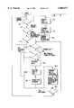
- FIG. 1illustrates a transfer device of the present invention connected to a television set, whereby caller information such as a telephone number of a calling party is displayed on a screen of the television set;
- FIG. 2illustrates a block diagram representing various components of one embodiment of the transfer device of the present invention
- FIG. 3illustrates another embodiment of the transfer device of the present invention, wherein means are provided which allow an indication of voice messaging information, received via the telephone line, onto a video screen;
- FIG. 4illustrates a particular embodiment of one remote control device which can be used with the transfer device of the present invention
- FIG. 5illustrates a particular embodiment of information processing circuitry which can be used with the transfer device of the present invention
- FIG. 6illustrates a flow diagram which represents the operation of various components of the information processing circuitry of FIG. 5;
- FIG. 7illustrates a particular implementation of a mute device to be used in the information processing circuitry shown in FIG. 5.
- FIG. 1shows a transfer device 10, in accordance with the present invention, connected to a television 20 via coaxial cable 22.
- Transfer device 10comprises a composite video input 12 and a telephone line input terminal 14.
- signal source 18comprises a composite video signal transmitted on an RF carrier.
- transfer device 10detects the presence of caller ID information passed by a telephone network through telephone line 16, and combines the caller ID information with a TV NTSC signal received at input terminal 12, thus placing the caller ID information on a television screen 24.
- the caller ID informationis displayed across the top of the screen in text form.
- the caller ID informationmay be placed on the screen of a TV using picture-in-picture technology, by using commercially available hardware.
- the phone directory number of a telephone, from which a communication present on the telephone line originatesis displayed on television screen 24.
- other information concerning the caller's identificatione.g., name or ID number
- the origine.g., the location or company name
- the present inventionis generally equally applicable to both, and reference to one will not preclude reference to the other.
- a microprocessor and memorymay be provided by which a user may store digital video images (from a camcorder, for example), for, e.g., representing parties who frequently call the user. Such images may be arranged in the form of a look-up table in the memory alongside their corresponding telephone numbers.
- transfer device 10having a microprocessor and memory, may compare the caller identifying information (i.e., the telephone number of the calling party) to the video images stored in the memory. Accordingly, once the video image corresponding to the detected telephone number is located, the corresponding video image may be displayed alone or in conjunction with the telephone number of the calling party on screen 24.
- the transfer device of the present inventionmay be provided with a look-up table and/or data retrieval system 72, as indicated by the dashed line in FIG. 3, used in conjunction with the aforementioned memory and microprocessor.
- the look-up table and/or data retrieval system 72may be configured to activate one of a plurality of preset messages to be transmitted to telephone line 16 upon use of a switch actuated by a user while watching the television.
- the television viewermay send a certain message to the party who is calling by simply pressing a button or message code.
- the television viewer/usermay send the caller a specific message.
- a list of preset messagesmay be stored in the memory which may be accessed by the microprocessor.
- the transfer device 10receives and decodes caller ID and/or voice messaging information via telephone line 16, and receives and demodulates an NTSC video signal 18 (e.g., from a cable service, TV antenna, or other NTSC compatible device) via composite video input terminal 12.
- Transfer device 10then decodes the caller ID and/or voice messaging information, demodulates the NTSC video signal to form a demodulated video signal, and combines the decoded caller ID and/or voice messaging information with the demodulated video signal. Thereafter, transfer device 10 remodulates and amplifies the demodulated video signal to form a final composite video signal at a standard NTSC television carrier frequency or channel.
- Transfer device 10outputs a final composite video signal via output terminal 11, which may be connected to any NTSC video signal compatible device, such as a television set, television monitor, VCR, cable box, and so on. While transfer device 10 as illustrated is a separate device, it could equally well be incorporated within, e.g., a television set, monitor, VCR, or cable box.
- a significant feature of the transfer device of the present inventionis that caller information or tele-communication information in conjunction with the transfer device of the present invention may be displayed on a standard television screen without interfering with a program currently being viewed by the user. Additionally, or in the alternative, transfer device 10 may decode signalling information provided by local exchange carriers (telephone companies) which would indicate the storage of voice, image or video messages at some remote location that has been placed there for the called party to retrieve at his or her convenience. This function is typically referred to as a "message waiting" indicator.
- FIG. 2illustrates, in more detail, a particular embodiment of the transfer device of the present invention.
- transfer device 10interfaces with a public switched telephone network via telephone line 16.
- Interface 48which comprises ring detect circuitry, is connected to caller ID decoder 46.
- the output of caller ID decoder 46is connected to a storage buffer 44, which is in turn connected to a processor 42.
- Processor 42is, in turn, connected to character generator 40.
- Composite video input terminal 12comprises an input terminal of tuner 26, the output of which is connected to the input of a demodulator 35.
- the output of demodulator 35is connected to the input terminal of a video/audio/sync separator 34.
- Each of three outputs of separator 34is respectively connected to audio detect device 32, video combiner 38, and sync switch 36.
- Sync switch 36comprises two output terminals, 37a, 37b, each of which is respectively connected to sync input 41b of character generator 40 and sync input 51c of NTSC modulator 50.
- Video format output 41c of character generator 40is connected to video combiner 38.
- Output terminal 39c of video combiner 38is connected to an input terminal 51b of NTSC modulator 50.
- Outputs of audio detect device 32, video combiner 38, and sync switch 36are each respectively connected to input terminals 51a, 51b, and 51c of NTSC modulator 50.
- Carrier or channel select switch 52is connected to a channel select input 51d of NTSC modulator 50.
- NTSC modulator 50comprises a transfer device output terminal 11.
- a remote tuner controller 30a, infrared or similar receiver 30b, and transmitter 30care connected in tandem to tuner 26.
- manual tuner control 28is connected to tuner 26.
- ring detect circuitryprovided within interface 48 determines the presence of an initial ring signal on telephone line 16. This information is detected by caller ID decoder 46, which prepares to receive and decode the caller ID information on telephone line 16. Caller ID decoder 46 receives this information (which is sent on telephone line 16 between the first and second rings), decodes the information, and places the information in storage buffer 44, where the information may be accessed by processor 42.
- Processor 42accesses the caller ID information stored in buffer 44, and provides it to character generator 40, which may comprise video display circuitry in the form of either PIP or overlay video display integrated circuits (ICs), in the appropriate video format.
- character generator 40may comprise video display circuitry in the form of either PIP or overlay video display integrated circuits (ICs), in the appropriate video format.
- Video display ICswill generate the appropriate video information (e.g., such as characters) in video format and provide this information, along with sync pulse information, in conjunction with sync pulse information received by character generator 40 at its sync input 41b.
- a composite video signal source 18is received at transfer device input 12 via tuner 26 and demodulator 35, and is passed to separator 34, which splits the composite video signal into its constituent parts for processing.
- separator device 34separates out audio, video, and sync signals from the demodulated composite video input signal.
- the separated video components of the demodulated composite video signalare input to video combiner 38, where they are combined with video formatted caller ID information, which is present at character input terminal 39b.
- a sync pulsealso separated out by separator circuit 34, is routed to sync switch 36 which, in conjunction with the sync signal which is input thereto, outputs two respective sync signals (or pulse signals) via output terminals 37a and 37b, which are respectively routed to sync inputs 41b and 51c of character generator 40 and NTSC modulator 50. Accordingly, video format caller ID information, output by character generator 40 at terminal 41c, is synchronized with input composite video signal source 18 which is input at transfer device input 12.
- Audio detect circuitry 32captures the audio signal components of the input composite video signal 18 for inclusion in the final composite video signal to be output by the transfer device at output 11.
- NTSC modulator circuitry 50Each of the constituent parts, output respectively from audio detecting circuitry 32, video combiner 38, and sync switch 36, are routed to NTSC modulator circuitry 50 where a final composite video signal is generated and processed for transmission to a compatible video device via transfer device output 11.
- NTSC modulator circuitrymodulates the signals input thereto to thereby translate the information into proper NTSC format, and moves the signals in the frequency domain by means of a carrier signal to a standard VHF channel, e.g., either of channels 3 or 4.
- the frequency band to which the final composite video signal is movedis centered around the frequency of the carrier signal which is selected by carrier or channel select switch 52.
- Channel select switch 52may be configured to choose, e.g., between carrier signal frequencies corresponding to either channel 3 or 4 of a standard VHF television channel.
- NTSC modulator circuitry 50recombines and modulates the audio signal, video signal, and sync signal, a final composite video signal is formed in proper NTSC format.
- the final composite video signalwhich contains video and audio information from composite video signal source 18, along with any caller ID or other information generated by character generator 40, will be displayed on the television screen.
- the final composite video signal input theretowill comprise the necessary information to cause such a concurrent or simultaneous display of the video, audio and caller ID information, should the final composite video signal be played back at any future time by the use of a monitor or television.
- FIG. 3partially illustrates another embodiment of the transfer device of the present invention, wherein a message waiting detector 56 is provided which allows the transfer device to indicate the presence of message waiting information on telephone line 16.
- the transfer device shown in FIG. 3in addition to providing caller ID information to a video format device, also decodes signalling information provided on telephone line 16 which would indicate the storage of voice, image, or video information at some remote location, whereby the information has been placed there for the called party to retrieve.
- similar elements as those shown in FIG. 2are depicted by the similar reference numerals.
- video demodulator means 35is shown connected to video processing device (video combiner) 38, the output of which is connected to NTSC modulator 50.
- Signal source 18is connected to a video input jack 64 which is connected to composite video input terminal 12 of transfer device 10.
- a remote control tuner device 30(which comprises controller 30a and receiver 30b; see FIG. 2) and remote control transmitter 30c are coupled to tuner 26.
- manual tuner control 28is connected to another input terminal of tuner 26.
- Output 27 of tuner 26is connected to the input of video demodulator 35.
- Transfer device 10is connected to a Public Switched Telephone Network via a standard modular telephone jack 54. Jack 54 is then connected to telephone interface 48, which comprises two outputs 49a and 49b. Interface output 49a is connected to message waiting detector 56, which has an output connected to input 43a of a processor 42. Interface output 49b is connected to a filter/demodulator device 46', which has an output connected to an input of a storage buffer 44. Storage buffer 44 is in turn connected to an input 43b of processor 42. The output 43c of processor 42 is connected to an input 41a of character generator 40. Output 41c of character generator device 40 is connected to a second input 39b of video processor (combiner) 38. Video output jack 74 is connected to output 11 of transfer device 10.
- telephone interface 48In order to process caller ID information, telephone interface 48 detects the presence of a standard telephone line ringing signal as defined in Bell System Voice Communications Technical Reference PUB 48005, January, 1980, the disclosure of which is expressly incorporated by reference herein in its entirety. In response to a detection of a first ring, telephone interface 48 sends a signal to filter/demodulator device 46' alerting device 46' to prepare for reception of caller ID data on telephone line 16. Information concerning the calling number, type of call, and other signalling information is passed to the customer via telephone line 16 (for both the embodiments and FIGS.
- the informationis transmitted between the first and second ringing periods as defined in Bellcore Publication TR-TSY-000031, entitled “Class (sm) Feature: Calling Number Delivery,” Issue 2, the disclosure of which is expressly incorporated by reference herein in its entirety).
- This informationis received from telephone line 16 by filter/demodulator device 46' and demodulated.
- Filter/demodulator device 46'demodulates the information so that it passes data in appropriate format to character generator 40 via buffer 44 and processor 42.
- Character generator 40in response to timing and data arrangement instructions from processor 42, generates characters (i.e., standard letters and numbers) in accordance with the data received from filter/demodulator device 46', and sends those characters to video processing device 38 via video process input 39b.
- Video processing device 38combines this information with the demodulated video signal which is present at the output of video demodulator 35.
- a composite video signalis present at the output of video processing device 38 that contains textual and icon information which may comprise the type of call, number of calls, and the identifying telephone number of the calling party.
- This composite (combined) video signal, output by video processing device 38 at output 39c,is input to NTSC modulator 50 which modulates the video signal by combining it with audio and sync information needed to produce an RF output that is compatible with standard televisions and VCRs (i.e., an NTSC format final composite video signal).
- the final composite video signalis then placed onto a standard VHF channel 3 or 4 by NTSC modulator 50, in accordance with the selected channel or carrier frequency selected by channel select switch 52.
- the final composite video signalis provided to video output jack 74, which may be connected to any NTSC compatible device for transfer of the information to a medium of expression.
- message waiting detector 56detects a condition representative of a message waiting or voice messaging status which is signalled on telephone line 16. Such a condition may comprise, e.g., a stuttering of the voltage present on telephone line 16. However, the condition detected may be of another form depending on the switch used by the local exchange carrier.
- message waiting detector 56sends a signal, indicating a message waiting status on telephone line 16, to processor 42, which instructs character generator device 40 to accordingly generate an appropriately chosen character or icon message to be sent to an NTSC compatible device such as a television, which is connected to transfer device output 11 via jack 74 (to be displayed on a screen).
- video processor 38combines the character message with a video signal output by video demodulator 35, and inputs the combined signal to NTSC modulator 50, which converts the signal into an appropriate final composite video signal to be sent to an NTSC compatible device.
- Character generator device 40may comprise any well known picture-in-picture or character display integrated circuit which may be purchased on the market.
- NECsupplies a CMOS LSI for 2 line ⁇ 12 column character display on an NTSC screen: Two types of standard LSI are provided: the ⁇ PD141C-001 and ⁇ PD6141G-101. Additionally, NEC also supplies a CMOS LSI for 2 line ⁇ 16 column character display on an NTSC screen. Two versions of this LSI are the ⁇ PD6143C-001 and ⁇ PD6143G-101.
- the transfer device of the present inventionis capable of operation as a "cable-ready" receiver, and provides users with first and second channel selection devices.
- the first channel selection devicecomprises a manual control key pad 28 which may display channel numbers representing the number of a channel being selected. Numbers selected on manual control key pad 28 are used to adjust the RF tuning of the tuner/receiver device 26, thus allowing selection of a predetermined filter present in tuner device 26 to choose the appropriate channel.
- Such television tuner and receiver performance characteristics and requirementsare well known to those in the art, and may be acquired through use of commercially available receivers. A list of known receivers may be found in column 2 of U.S. Pat. No. 4,405,946, which is expressly incorporated by reference herein in its entirety.
- a second channel changing devicemay comprise an infrared remote control device 30, 30c.
- Remote control transmitter 30csends signalling data, via the infrared spectrum, to remote tuner control device 30.
- the signalling device received by remote tuner control device 30is used to select an appropriate filter in the tuner device which corresponds to the desired television channel.
- An infrared remote control transmitter 30cmay also be configured to provide volume control capabilities.
- Tuner 26may comprise a plurality of band pass filters, whereby the center frequency of one or more of the band pass filters may be varied.
- a switching devicewhich in the embodiment of FIGS. 2 and 3 comprises tuner controls 28, 30 (30a and 30b), and 30c, is provided to allow selection between each of the band pass filters.
- the transfer devicemay be configured to provide caller ID or message waiting information on a television screen if connected to an ISDN line.
- the telephone line interface 48 and filter demodulator device 46would be replaced by an ISDN telephone line interface device, and a D channel filter/demodulator device capable of obtaining caller ID information provided by the ISDN architecture's D channel. Once this D channel caller ID information is obtained and passed to the character generator device 40, via buffer 44 and processor 42, the transfer device will operate exactly as previously described with reference to FIGS. 2 and 3.
- FIG. 4shows infrared remote control transmitter 30c according to the embodiment shown in FIG. 3 of the transfer device of the present invention.
- infrared remote control transmitter 30cmay be provided with a number of features, including a switch 60 for turning the transfer device on and off, a caller ID on/off switch 62 which may control the supply of power to the caller ID generation components of the transfer device, such as character generator device 40, processor 42, buffer 44, message waiting detector 56, filter/demodulator device 46', and telephone interface 48'.
- a numerical key pad 66is provided on infrared remote control transmitter 30c, and additionally channel increase and decrease buttons 68,68, along with volume increase and decrease buttons 70,70, may be provided to control decrementation and incrementation of the channel number (corresponding to certain defined filters selected in the tuner device) and volume level (i.e., the level of the final composite video signal output by the transfer device).
- FIGS. 2 and 3 of the transfer device of the present inventionhave been pointed out along with the function thereof. As to the specific implementations of certain elements, implementations of these elements is within the skill of the ordinary artisan. Many of these elements employed may be implemented with use of commercially available components and/or are described in previous patents or publications which would enable one of ordinary skill in the art to construct such components.
- apparatus for tuning and demodulating the composite video signal source 18including portions corresponding to tuner 26, manual tuner control 28, remote tuner control components 30 (30a, 30b) and 30c, and demodulator 35) may be implemented in the form of a commercially available television receiver. Tuning and demodulating apparatus along with other components depicted in the embodiments of FIGS.
- U.S. Pat. No. 4,924,496 issued to FIGA et al.discloses example configurations and implementations of similar or equivalent elements in greater detail in conjunction with an automatic incoming telephone call originating number and party display system.
- U.S. Pat. No. 4,924,496is thus also expressly incorporated by reference herein in its entirety.
- a telephone interface circuit 72which includes a filter and demodulation circuit 80, a ring interface circuit 78, a modular telephone jack 74, and a universal synchronous receiver/transmitter (UART) 84.
- UARTuniversal synchronous receiver/transmitter
- FIG. 5illustrates information processing circuitry 110 which can be used in conjunction with the transfer device of the present invention.
- a microprocessor 88is connected to video circuitry 114 via a bus 106.
- the video circuitrymay include, for example, an image generator, such as character generator 40 (see FIGS. 2 and 3), and various signal processing elements connected thereto, such as video combiner 38. Accordingly, by making such a connection, information processing circuitry 110, which is shown in FIG. 5, may be incorporated into either of the embodiments of the transfer device as shown in FIGS. 2 and 3 of the present invention.
- a ring detect circuit 90is connected between incoming telephone line 86 and an input of microprocessor 88.
- a message waiting detector 92is connected between telephone line 86 and an input of microprocessor 88.
- a tone detector 94 and a parallel phone detector 100are each connected between telephone line 86 and respective inputs of microprocessor 88.
- a tone generator 96is connected to telephone line 86, and includes an input which is connected to an output enable line of microprocessor 88.
- An FSK (Frequency Shift Keying) receiver 98is also coupled to telephone line 86, and comprises both an enabling terminal 99a and an output terminal 99b, both of which are connected to microprocessor 88.
- a mode setting switch SW1is connected to an input of microprocessor 88.
- a mute device 102is connected in series between a phone 104 and telephone line 86. Mute device 102 includes an enabling terminal 103 which is connected to microprocessor 88.
- Various devicesmonitor assorted activities on the Tip and Ring (TR) of telephone line 86, and under stored program control, microprocessor 88 interprets these monitored activities, and performs one or more necessary actions via enabling devices such as tone generator 96, FSK receiver 98, and mute device 102.
- TRTip and Ring
- a flow diagram shown in FIG. 6illustrates the operation of the various devices shown in FIG. 5, as controlled by microprocessor 88 under stored program control.
- information processing circuitry 110In order to provide on-hook Calling Identity Delivery (CID), information processing circuitry 110 must detect the presence of a power ringing on TR. Accordingly, at step S1, a determination is made as to whether or not power ringing exists on incoming telephone line 86. Once ringing is detected, as determined at step S1, the microprocessor will enable FSK receiver 98 to begin receiving data which is embedded between the first and second ring cycles on telephone line 86. This data is then forwarded in step S5 to the appropriate video circuitry for subsequent processing and conversion to a medium of expression, such as characters on a television screen.
- a medium of expressionsuch as characters on a television screen.
- microprocessor 88enables message waiting device 92 (FIG. 5) to detect whether or not a signal is present on incoming telephone line 86, which indicates the presence of a stored message in a remote message center. If the signal is present on the telephone line, microprocessor 88 proceeds to step S6, where the appropriate message waiting indicator or data is forwarded to video circuitry 114. Video circuitry 114 will accordingly process the indicator or data, and may, for example, display a predetermined message or signal which indicates the presence of a message in the remote messaging center.
- microprocessor 88will proceed to step S3, where a determination is made as to whether phone 104 is in an off-hook condition, and a connection is established between a caller and a receiver (for example, in a stable two party conversation). Upon detection of such an off-hook condition at step S3, a further determination is made at step S7, as to whether a Customer Premises Equipment (CPE) alerting tone is present on incoming telephone line 86.
- CPECustomer Premises Equipment
- a CPE alerting tonewill typically follow an audible tone which is sent to an ear piece of telephone 104 in response to a Calling Identity Delivery on Call Waiting condition being activated on telephone line 86. Subsequent to sending this audible tone, the SPCS will then transmit a Customer Premises Equipment (CPE) alerting tone to the telephone line 86 which will be detected by information processing circuitry 110 via tone detector 94 (FIG. 5). Tone detector 94 will receive this signal and accordingly alert microprocessor 88, which will then proceed from step S7 to S7.1.
- CPECustomer Premises Equipment
- step S7If CPE alerting tone is not detected as determined at step S7, microprocessor 88 will proceed to step S14. If telephone (FIG. 5) remains off-hook, step S7 will be repeated. If telephone 104 is on-hook at step S14, microprocessor will return to step S1.
- step S7.1microprocessor 88 determines if the device has been set in a primary call waiting receiver mode (i.e., if switch SW1 is closed). If so, microprocessor 88 proceeds to step S8. If the primary mode is not set, microprocessor 88 will jump to step S11.
- step S8microprocessor 88 will determine, via parallel phone detector 100, whether any parallel phones are connected to telephone line 86, in an off-hook condition. Upon detection that parallel phones, which are in an off-hook condition, are connected to telephone line 86, microprocessor 88 will proceed to step S14 to determine if telephone 104 (FIG. 5) remains off-hook. If so, step S7 will be repeated.
- microprocessor 88is programmed to wait (and not continue with a detection and transfer of data with the SPCS to thus perform a Caller Identity Delivery with Call Waiting function) until all parallel phones which are in an off-hook condition have been placed in an on-hook condition. This is to prevent any unwanted interference which may be provided via the parallel telephones, and in addition prevent the generation of data tones in the ear pieces of the one or more parallel telephones.
- microprocessor 88determines in step S8 that no off-hook parallel phones are connected to telephone line 86 (by receipt of the appropriate signal from parallel phone detector 100), microprocessor 88 will continue to step S9, and activate mute device 102 via enable terminal 103.
- mute device 102When activated, mute device 102 temporarily disconnects the telephone line 86 from telephone 104, and simulates an off-hook condition on telephone line 86, so that the SPCS does not detect an on-hook condition.
- microprocessor 88enables tone generator 96 to send an acknowledgement (ACK) tone to the SPCS.
- step S11microprocessor 88 enables FSK receiver 98, via enable terminal 99a, to receive the calling identity information from telephone line 86, which will be passed to microprocessor 88 via output terminal 99b.
- step S12microprocessor 88 accordingly forwards the data received in step S11 to video circuitry 114 (not shown). Subsequent to receiving and forwarding the data to video circuitry 114, i.e., once data transmission is complete, in step S13, microprocessor 88 disables FSK receiver 98, and deactivates mute device 102 (if necessary).
- step S14microprocessor 88 determines whether telephone 104 remains in an off-hook condition. If not, the process is returned to step S1. If the telephone is still in an off-hook condition, thus being capable of receiving further Calling Identity on Call Waiting information, the process is returned to step S7, where microprocessor 88 will await a CPE alerting tone.
- the transfer device of the present inventionin the embodiment illustrated in FIG. 5, has two modes of operation: a primary call waiting receiver mode, and a secondary call waiting receiver mode.
- a primary receiver modewhich is set by switch SW1 (when in the closed position) and determined by microprocessor 88 at step S7, microprocessor 88 performs steps S8-S10.
- microprocessor 88When in the secondary receiver mode, microprocessor 88 foregoes execution of steps S8-S10, and skips to step S11 to enable the FSK receiver.
- the secondary receiver modeis provided in the event a primary call waiting receiver (comprising, e.g., a peripheral/external device) is connected to telephone line 86, which will perform the functions of muting the telephone line 86 and generating an acknowledgement "ACK" tone.
- a primary call waiting receivercomprising, e.g., a peripheral/external device
- the transfer device of the present inventionis configured (by switch SW1--when in the open position) as a secondary receiver, and will not check for parallel phones, mute the telephone line or generate an acknowledgement (ACK) tone.
- a mute device 102which temporarily disconnects telephone set 104 from telephone line 86 in order to effect a CIDCW information transfer. Simultaneously, while temporarily disconnecting telephone line 86 from telephone set 104, mute device 102 simulates an off-hook condition on telephone line 86, by drawing the appropriate level of current from the central office which is connected to telephone lines 86. Thereafter, when the mute device is disabled, switching device 80 (see FIG. 7) is returned to a position at which telephone 104 is reconnected to telephone line 86.
- an entire unitary transfer device 10(see, e.g., FIG. 1), embodying the information processing circuit 110 of FIG. 5, may be connected between telephone line 86 and telephone 104.
- FIG. 7depicts one presently contemplated embodiment for implementing the mute device 102 in the information processing circuitry shown in FIG. 5.
- Alternative circuitswhich may be, e.g., commercially available, or readily constructed by one of ordinary skill in the art, may be utilized to implement mute device 102.
- a switching device 80is placed between the Ring and Tip of telephone line 86 and telephone 104.
- An isolation device 82e.g., a transformer, is connected between switching device 80 and a load 84, and serves to electrically isolate load 84 from switching device 80.
- Switching device 80when enabled by microprocessor 88 via enable input 103, disconnects telephone 104 from telephone line 86, and connects telephone line 86 with input terminals of isolation device 82. Upon receiving a disable signal from microprocessor 88, switching device 80 disconnects isolation device 82 from telephone line 86, and returns the connection between telephone line 86 and telephone 104.
- Switching device 80can comprise, e.g., a commercially available DPDT relay, such as W103MPCX-31, which is provided by Magnecraft.
- Load 84can comprise, e.g., any commercially available resistive load having the level of impedance needed to give the appropriate balance to remaining portions of the circuit, e.g., a resistor (having, e.g., a 600 ohm load) alone, or a resistor and capacitor used together.
- Isolation device 82may include, e.g., an appropriate commercially available telephone line transformer, such as FF-1700, which is provided by Young-Shin Electronics. Use of these devices, however should not be considered as limiting the present invention.
- isolation device 82will preferably have the appropriate DC resistance so as to draw the needed current which would serve to simulate an off-hook condition of a telephone connected to telephone line 86 and thus "fool" the central office.
- Switching device 80must successfully reconfigure the connection between telephone line 86 and telephone 104 within a predetermined time period, such as that defined in LSSGR (LATA Switching Systems Generic Requirements), Section 6.3.5.2, Bellcore document FR-NWT-000064, which is expressly incorporated by reference herein. If the reconfiguration (which includes switching of switching device 80 into a condition which temporarily disconnects telephone 104 from telephone line 86) is not completed within this time period, the activities of switching device 80 may be viewed by the central office as a switchhook flash which will cause the SPCS to place the current caller on "hold” and connect a third source (i.e., the call requesting party) directly to telephone line 86.
- LSSGRLATA Switching Systems Generic Requirements
- Section FR-NWT-000064Bellcore document FR-NWT-000064
- switching device 80is preferably configured to maintain a connection between telephone line 86 and telephone 104 when no power is applied.
- mute circuit 102will not impede the normal operation of the customer's telephone set 104.
Landscapes
- Engineering & Computer Science (AREA)
- Signal Processing (AREA)
- Multimedia (AREA)
- Telephone Function (AREA)
- Telephonic Communication Services (AREA)
Abstract
Description
Claims (8)
Priority Applications (4)
| Application Number | Priority Date | Filing Date | Title |
|---|---|---|---|
| US07/911,471US5805677A (en) | 1991-07-11 | 1992-07-10 | Apparatus for facilitating the display of information relating to the origin of a third source caller |
| IL106169AIL106169A0 (en) | 1992-07-10 | 1993-06-29 | Tele-communication information display system and method for transferring caller information to a video device |
| MX9304124AMX9304124A (en) | 1992-07-10 | 1993-07-08 | TELECOMMUNICATION INFORMATION DISPLAY SYSTEM. |
| US09/136,401US6052444A (en) | 1991-07-11 | 1998-08-19 | Tele-communication information display system |
Applications Claiming Priority (2)
| Application Number | Priority Date | Filing Date | Title |
|---|---|---|---|
| US72834191A | 1991-07-11 | 1991-07-11 | |
| US07/911,471US5805677A (en) | 1991-07-11 | 1992-07-10 | Apparatus for facilitating the display of information relating to the origin of a third source caller |
Related Parent Applications (1)
| Application Number | Title | Priority Date | Filing Date |
|---|---|---|---|
| US72834191AContinuation-In-Part | 1991-07-11 | 1991-07-11 |
Related Child Applications (1)
| Application Number | Title | Priority Date | Filing Date |
|---|---|---|---|
| US09/136,401ContinuationUS6052444A (en) | 1991-07-11 | 1998-08-19 | Tele-communication information display system |
Publications (1)
| Publication Number | Publication Date |
|---|---|
| US5805677Atrue US5805677A (en) | 1998-09-08 |
Family
ID=46202062
Family Applications (2)
| Application Number | Title | Priority Date | Filing Date |
|---|---|---|---|
| US07/911,471Expired - LifetimeUS5805677A (en) | 1991-07-11 | 1992-07-10 | Apparatus for facilitating the display of information relating to the origin of a third source caller |
| US09/136,401Expired - LifetimeUS6052444A (en) | 1991-07-11 | 1998-08-19 | Tele-communication information display system |
Family Applications After (1)
| Application Number | Title | Priority Date | Filing Date |
|---|---|---|---|
| US09/136,401Expired - LifetimeUS6052444A (en) | 1991-07-11 | 1998-08-19 | Tele-communication information display system |
Country Status (1)
| Country | Link |
|---|---|
| US (2) | US5805677A (en) |
Cited By (53)
| Publication number | Priority date | Publication date | Assignee | Title |
|---|---|---|---|---|
| US5907604A (en)* | 1997-03-25 | 1999-05-25 | Sony Corporation | Image icon associated with caller ID |
| US6014434A (en)* | 1996-06-27 | 2000-01-11 | Samsung Electronics Co., Ltd. | Method for controlling and processing an incoming call of a line-busy exchange system |
| US6052444A (en)* | 1991-07-11 | 2000-04-18 | Sbc Technology Resources, Inc. | Tele-communication information display system |
| US6061435A (en)* | 1997-10-03 | 2000-05-09 | Lucent Technologies Inc. | Cordless telephone system having a handset with non-telephone functionality |
| US6154531A (en)* | 1998-11-13 | 2000-11-28 | Intel Corporation | Telephone caller identification system |
| US6215515B1 (en)* | 1992-02-19 | 2001-04-10 | Netergy Networks, Inc. | Videocommunicating device with an on-screen telephone keypad user-interface method and arrangement |
| US6269159B1 (en)* | 1998-04-15 | 2001-07-31 | Agere Systems Guardian Corp. | Conferencing with a calling party |
| US6278773B1 (en)* | 1996-06-03 | 2001-08-21 | Webtv Networks, Inc. | Determining and disclosing the indentity of telephone caller |
| US6292544B1 (en)* | 1998-04-06 | 2001-09-18 | Ag Communcation Systems Corporation | Message waiting indicator in a computer integrated telephony system |
| US6366772B1 (en)* | 1999-07-22 | 2002-04-02 | Xircom Wireless, Inc. | Caller identification delivery in a wireless local loop or other systems |
| US6438216B1 (en)* | 1998-07-30 | 2002-08-20 | Siemens Information And Communication Networks, Inc. | Nonintrusive call notification method and system using content-specific information |
| WO2003005709A1 (en)* | 2001-07-04 | 2003-01-16 | Siemens Aktiengesellschaft | System for switching, controlling, programming and operating communications devices |
| US20030190018A1 (en)* | 2002-04-03 | 2003-10-09 | Bleile Leonard George | Apparatus, method, media and signals for controlling a wireless communication appliance |
| US6665375B1 (en)* | 2000-11-21 | 2003-12-16 | International Business Machines Corporation | Method and apparatus for providing accessibility to call connection status |
| US6714637B1 (en) | 1999-10-19 | 2004-03-30 | Nortel Networks Limited | Customer programmable caller ID alerting indicator |
| US6763095B1 (en)* | 2002-09-24 | 2004-07-13 | Verizon Laboratories Inc. | Unified messaging system and method |
| US6768722B1 (en) | 2000-06-23 | 2004-07-27 | At&T Corp. | Systems and methods for managing multiple communications |
| US20040161083A1 (en)* | 2002-02-19 | 2004-08-19 | Sbc Properties, L.P. | Method and system for presenting customized call alerts in a service for internet caller identification |
| US6816481B1 (en) | 1999-04-09 | 2004-11-09 | Sbc Technology Resources, Inc. | Internet caller identification system and method |
| US20040251887A1 (en)* | 2001-09-20 | 2004-12-16 | Sparrell Carlton J | Centralized resource manager with power switching system |
| EP1501072A4 (en)* | 2002-03-25 | 2005-07-20 | Yoshihiko Sano | Representation generation method, representation generation device, and representation generation system |
| US20050190903A1 (en)* | 2004-02-26 | 2005-09-01 | Nokia Corporation | Text-to-speech and midi ringing tone for communications devices |
| US20050190746A1 (en)* | 2004-02-27 | 2005-09-01 | Innomedia Pte Ltd. | Band signal detection and presentation for IP phone |
| US6981216B1 (en)* | 2000-11-09 | 2005-12-27 | Brandes George A | Method and system for subpoena generation including time-dependent reverse number search |
| US6996214B1 (en)* | 2001-08-31 | 2006-02-07 | Silicon Laboratories, Inc. | Utilization of in-band signaling to facilitate modem on hold |
| US7020488B1 (en) | 2000-07-19 | 2006-03-28 | Embedded Systems Products Inc. | Communications unit, system and methods for providing multiple access to a wireless transceiver |
| US7031453B1 (en) | 2001-03-19 | 2006-04-18 | Nortel Networks Limited | Telephony ring customization |
| US7263178B1 (en) | 2002-09-24 | 2007-08-28 | Verizon Laboratories Inc. | Automated communications assistant and method |
| US20070211139A1 (en)* | 2006-03-13 | 2007-09-13 | Oki Electric Industry Co., Ltd. | Video reproducing apparatus with telephone control functions |
| US20070226344A1 (en)* | 2004-07-23 | 2007-09-27 | General Instrument Corporation | Centralized Resource Manager With Power Switching System |
| US20070297580A1 (en)* | 1996-08-14 | 2007-12-27 | Corbett Joseph C | Video caller identification systems and methods |
| US20080019494A1 (en)* | 2004-10-04 | 2008-01-24 | Matsushita Electric Industrial Co., Ltd. | Telephone Device |
| US20080242293A1 (en)* | 2007-04-02 | 2008-10-02 | Cequint, Inc. | System and method for providing caller id name display in wireless communications system |
| US20090280788A1 (en)* | 2005-01-14 | 2009-11-12 | Riku Suomela | Method, device or computer program for enabling communication from a remote party to a user of a device while the user participates in an active application at the device |
| US20100075644A1 (en)* | 2008-09-22 | 2010-03-25 | Cequint, Inc. | Delivery of caller identification data to a mobile device using application directed short messaging service |
| USRE41416E1 (en) | 2000-09-05 | 2010-07-06 | Flexiworld Technologies, Inc. | Apparatus, methods and systems for anonymous communication |
| US7770196B1 (en) | 1992-12-09 | 2010-08-03 | Comcast Ip Holdings I, Llc | Set top terminal for organizing program options available in television delivery system |
| US7809121B2 (en) | 2001-06-22 | 2010-10-05 | At&T Intellectual Property I, L.P. | Identification of calling devices dialing a universal number to access a telecommunications relay service center |
| US20100261459A1 (en)* | 2009-04-13 | 2010-10-14 | Cequint, Incorporated | System and method for enhanced display of in-network caller information on a mobile device |
| US20100261462A1 (en)* | 2009-04-13 | 2010-10-14 | Cequint, Incorporated | System and method for local handset check of the nxx local exchange to determine carrier |
| US20100261461A1 (en)* | 2009-04-13 | 2010-10-14 | Cequint, Incorporated | System and method for refreshing caller directory data |
| US20110274255A1 (en)* | 2006-10-31 | 2011-11-10 | At&T Intellectual Property I, L.P. | System and Method of Audible Caller Identification Via a Multimedia Device |
| US20110310213A1 (en)* | 2010-06-18 | 2011-12-22 | Comcast Cable Communication, Llc | Centralized Communication Hub for Displaying Calls and Messages on a Display |
| US20120021844A1 (en)* | 2010-07-23 | 2012-01-26 | Dean Ronald Thompson | Pvc shell skatepark |
| US8248506B2 (en) | 1998-07-17 | 2012-08-21 | Sony Corporation | Imaging apparatus |
| US8364177B2 (en) | 2009-04-13 | 2013-01-29 | Cequint, Inc. | System and method for determination of network and conditional execution of applications and promotions |
| US8578410B2 (en) | 2001-08-03 | 2013-11-05 | Comcast Ip Holdings, I, Llc | Video and digital multimedia aggregator content coding and formatting |
| US8621521B2 (en) | 2001-08-03 | 2013-12-31 | Comcast Ip Holdings I, Llc | Video and digital multimedia aggregator |
| US8644470B2 (en) | 2008-04-15 | 2014-02-04 | Cequint, Inc. | Methods and systems for improved caller name identification on a telephone network |
| US8654943B2 (en) | 2006-04-14 | 2014-02-18 | At&T Intellectual Property I, L.P. | System and method of enhanced caller-ID display using a personal address book |
| US9078014B2 (en) | 2000-06-19 | 2015-07-07 | Comcast Ip Holdings I, Llc | Method and apparatus for targeting of interactive virtual objects |
| US9286294B2 (en) | 1992-12-09 | 2016-03-15 | Comcast Ip Holdings I, Llc | Video and digital multimedia aggregator content suggestion engine |
| US10278009B2 (en)* | 2012-11-30 | 2019-04-30 | Tribune Broadcasting Company, Llc | Systems and methods for using caller data to set an operational mode of a phone switch |
Families Citing this family (33)
| Publication number | Priority date | Publication date | Assignee | Title |
|---|---|---|---|---|
| US6058172A (en)* | 1997-07-10 | 2000-05-02 | Cybiotronics Limited | Telephone with novel FSK decoding means, simultaneous off-hook caller ID reception means, and set of configurable function key means |
| KR100547841B1 (en)* | 1998-12-26 | 2006-05-10 | 삼성전자주식회사 | Control Method of Operation Mode Switching of Television Mobile Phone |
| AU7074200A (en)* | 1999-08-27 | 2001-03-26 | Raj Mahadevaiah | Telephone interceptor |
| CN1196307C (en)* | 1999-11-04 | 2005-04-06 | 皇家菲利浦电子有限公司 | Communication device for integrating voice mail services and TV functions |
| KR100555703B1 (en)* | 1999-11-30 | 2006-03-03 | 엘지전자 주식회사 | How to Receive Ad Text Message Using Caller ID on Phone |
| US6690675B1 (en) | 1999-12-30 | 2004-02-10 | At&T Corp. | User programmable fail-proof IP hotline/warm-line |
| US7120139B1 (en) | 1999-12-30 | 2006-10-10 | At&T Corp. | Broadband cable telephony network architecture IP ITN network architecture reference model |
| US6678265B1 (en) | 1999-12-30 | 2004-01-13 | At&T Corp. | Local number portability database for on-net IP call |
| US6826173B1 (en) | 1999-12-30 | 2004-11-30 | At&T Corp. | Enhanced subscriber IP alerting |
| US7180889B1 (en)* | 1999-12-30 | 2007-02-20 | At&T Corp. | Personal control of address assignment and greeting options for multiple BRG ports |
| US6775267B1 (en) | 1999-12-30 | 2004-08-10 | At&T Corp | Method for billing IP broadband subscribers |
| US6937713B1 (en) | 1999-12-30 | 2005-08-30 | At&T Corp. | IP call forward profile |
| US6816469B1 (en) | 1999-12-30 | 2004-11-09 | At&T Corp. | IP conference call waiting |
| US6633635B2 (en) | 1999-12-30 | 2003-10-14 | At&T Corp. | Multiple call waiting in a packetized communication system |
| KR20010065803A (en)* | 1999-12-30 | 2001-07-11 | 윤종용 | Method for changing timbre during conversation in portable telephone |
| US6728239B1 (en) | 1999-12-30 | 2004-04-27 | At&T Corp. | Scaleable network server for low cost PBX |
| US6917610B1 (en) | 1999-12-30 | 2005-07-12 | At&T Corp. | Activity log for improved call efficiency |
| US6680935B1 (en) | 1999-12-30 | 2004-01-20 | At&T Corp. | Anonymous call rejection |
| US7075918B1 (en) | 1999-12-30 | 2006-07-11 | At&T Corp. | BRG with PBX capabilities |
| US6889321B1 (en) | 1999-12-30 | 2005-05-03 | At&T Corp. | Protected IP telephony calls using encryption |
| US6671262B1 (en) | 1999-12-30 | 2003-12-30 | At&T Corp. | Conference server for automatic x-way call port expansion feature |
| US6775273B1 (en) | 1999-12-30 | 2004-08-10 | At&T Corp. | Simplified IP service control |
| US6678362B2 (en)* | 2002-01-31 | 2004-01-13 | Sony Corporation | System and method for effectively managing telephone functionality by utilizing a settop box |
| DE20201823U1 (en)* | 2002-02-06 | 2002-05-02 | Meiloon Industrial Co., Ltd., Taipeh/T'ai-pei | Image / sound output device with identification and volume control |
| US6831969B2 (en)* | 2002-04-04 | 2004-12-14 | Innomedia Pre Ltd. | Caller ID display system for telephony over a packet switched network |
| US20040125929A1 (en)* | 2002-12-31 | 2004-07-01 | Pope Stephen M. | Projection caller ID |
| US7286799B2 (en)* | 2003-03-04 | 2007-10-23 | Steven Thrasher | Remote caller identification (ID) device |
| EP1501319B1 (en)* | 2003-07-24 | 2008-01-23 | France Telecom | Method and system for placing messages in the inbox of a message service |
| US20050249344A1 (en)* | 2004-05-07 | 2005-11-10 | Sbc Knowledge Ventures, L.P. | Network delivery of personalized caller identification |
| US7940746B2 (en) | 2004-08-24 | 2011-05-10 | Comcast Cable Holdings, Llc | Method and system for locating a voice over internet protocol (VoIP) device connected to a network |
| US8867524B1 (en)* | 2005-09-30 | 2014-10-21 | At&T Intellectual Property Ii, L.P. | Method and apparatus for activating an incoming call voice session on a video display device |
| US7515698B2 (en) | 2006-04-17 | 2009-04-07 | At & T Intellectual Property I, L.P. | System and method for providing telephone call notification and management in a network environment |
| US8953761B2 (en)* | 2008-12-30 | 2015-02-10 | Centurylink Intellectual Property Llc | System, method, and apparatus for inserting caller ID information into a digital video signal |
Citations (36)
| Publication number | Priority date | Publication date | Assignee | Title |
|---|---|---|---|---|
| US3934079A (en)* | 1973-10-26 | 1976-01-20 | Jerrold Electronics Corporation | Bilateral communications system for distributing commerical and premium video signaling on an accountable basis |
| FR2305078A1 (en)* | 1975-03-21 | 1976-10-15 | Acet Srl | Monitor television and internal telephone interconnection system - uses two conductor wires and system is controlled from push button selector |
| FR2320670A1 (en)* | 1975-08-07 | 1977-03-04 | Guichard Jacques | Information system for videophone network - automatically stores information transmitted to unattended installation for reconstitution later |
| US4338492A (en)* | 1980-01-02 | 1982-07-06 | Zenith Radio Corporation | Television receiver with two-way telephone conversation capability |
| US4349701A (en)* | 1980-01-02 | 1982-09-14 | Zenith Radio Corporation | Television receiver with two-way telephone conversation and dial-out capabilities |
| US4356509A (en)* | 1981-03-12 | 1982-10-26 | Zenith Radio Corporation | Microcomputer-controlled television/telephone system and method therefore |
| US4405946A (en)* | 1982-02-16 | 1983-09-20 | Rca Corporation | Television signal converting apparatus providing an on-screen tuning display |
| US4456925A (en)* | 1982-10-04 | 1984-06-26 | Zenith Radio Corporation | Television/telephone system with automatic dialing |
| US4582956A (en)* | 1983-07-12 | 1986-04-15 | At&T Bell Laboratories | Method and apparatus for displaying at a selected station special service information during a silent interval between ringing |
| BR8603764A (en)* | 1986-08-01 | 1988-05-17 | Digitro Sistema Eletronicos Lt | CALLING SUBSCRIBER IDENTIFICATION SYSTEM |
| US4805210A (en)* | 1987-09-10 | 1989-02-14 | Griffith Jr Herbert L | Automatic telephone line sharing and lockout apparatus |
| US4805205A (en)* | 1980-06-11 | 1989-02-14 | Andre Faye | Method and device for establishing bidirectional communications between persons located at different geographically distant stations |
| JPS6478059A (en)* | 1987-09-18 | 1989-03-23 | Fujitsu Ltd | Adaptor for telephone set |
| JPH0191560A (en)* | 1987-10-02 | 1989-04-11 | Nec Corp | Incoming display system in telephone set |
| US4852151A (en)* | 1988-02-24 | 1989-07-25 | Hayes Microcomputer Products, Inc. | Modem with call waiting |
| US4873719A (en)* | 1988-11-18 | 1989-10-10 | Morris Reese | Enhanced calling number delivery service system |
| GB2223911A (en)* | 1988-10-14 | 1990-04-18 | Hashimoto Corp | Telephone answering machine with TV |
| JPH02113657A (en)* | 1988-10-21 | 1990-04-25 | Nippon Telegr & Teleph Corp <Ntt> | Presentation screen system |
| US4922523A (en)* | 1984-12-29 | 1990-05-01 | Hashimoto Corporation | Videotex with telephone call screening system |
| US4924496A (en)* | 1988-05-12 | 1990-05-08 | Romek Figa D/B/A Abraham & Sons | Automatic incoming telephone call originating number and party display system |
| JPH02202278A (en)* | 1989-01-31 | 1990-08-10 | Nec Corp | Display telephone set for telephone incoming message to external monitoring television |
| JPH02229361A (en)* | 1989-03-02 | 1990-09-12 | Jutaku Manejimento:Kk | Installation structure of unit furniture for house |
| US4974085A (en)* | 1989-05-02 | 1990-11-27 | Bases Burke Institute, Inc. | Television signal substitution |
| US4989081A (en)* | 1988-11-14 | 1991-01-29 | Sony Corporation | Home-bus-information system |
| JPH0329456A (en)* | 1989-06-26 | 1991-02-07 | Nec Corp | Display system for telephone caller name |
| US4995074A (en)* | 1989-04-03 | 1991-02-19 | Goldman Bruce J | Switched line modem interface system |
| US5029199A (en)* | 1989-08-10 | 1991-07-02 | Boston Technology | Distributed control and storage for a large capacity messaging system |
| US5046093A (en)* | 1989-09-05 | 1991-09-03 | General Instrument Corporation | CATV subscriber apparatus with intelligent remote control |
| US5061992A (en)* | 1989-01-24 | 1991-10-29 | Kabushiki Kaisha Toshiba | Tv phone communication system and apparatus therefor |
| US5073927A (en)* | 1989-08-29 | 1991-12-17 | Motorola, Inc. | Imaging identification method for a communication system |
| US5083205A (en)* | 1989-07-18 | 1992-01-21 | Sony Corporation | Television receiver with memory recall of television broadcast channel and system |
| US5099331A (en)* | 1987-09-04 | 1992-03-24 | Texas Instruments Incorporated | Apparatus for overlaying a displayed image with a second image |
| US5109279A (en)* | 1988-03-28 | 1992-04-28 | Kabushiki Kaisha Toshiba | Television receiver with teletext receiving function and a method for superimposing a teletext picture on a television picture |
| US5117452A (en)* | 1989-09-29 | 1992-05-26 | David Callele | Telephone interface for a computer for receiving and transmitting information during the silent interval between ringing |
| US5138649A (en)* | 1990-11-16 | 1992-08-11 | General Instrument Corporation | Portable telephone handset with remote control |
| US5148275A (en)* | 1990-11-15 | 1992-09-15 | Thomson Consumer Electronics, Inc. | Second video program |
Family Cites Families (2)
| Publication number | Priority date | Publication date | Assignee | Title |
|---|---|---|---|---|
| US5343516A (en)* | 1989-09-29 | 1994-08-30 | Digital Systems Group, Inc. | Computer telecommunications signalling interface |
| US5805677A (en)* | 1991-07-11 | 1998-09-08 | Sbc Technology Resources, Inc. | Apparatus for facilitating the display of information relating to the origin of a third source caller |
- 1992
- 1992-07-10USUS07/911,471patent/US5805677A/ennot_activeExpired - Lifetime
- 1998
- 1998-08-19USUS09/136,401patent/US6052444A/ennot_activeExpired - Lifetime
Patent Citations (38)
| Publication number | Priority date | Publication date | Assignee | Title |
|---|---|---|---|---|
| US3934079A (en)* | 1973-10-26 | 1976-01-20 | Jerrold Electronics Corporation | Bilateral communications system for distributing commerical and premium video signaling on an accountable basis |
| FR2305078A1 (en)* | 1975-03-21 | 1976-10-15 | Acet Srl | Monitor television and internal telephone interconnection system - uses two conductor wires and system is controlled from push button selector |
| FR2320670A1 (en)* | 1975-08-07 | 1977-03-04 | Guichard Jacques | Information system for videophone network - automatically stores information transmitted to unattended installation for reconstitution later |
| US4338492A (en)* | 1980-01-02 | 1982-07-06 | Zenith Radio Corporation | Television receiver with two-way telephone conversation capability |
| US4349701A (en)* | 1980-01-02 | 1982-09-14 | Zenith Radio Corporation | Television receiver with two-way telephone conversation and dial-out capabilities |
| US4805205A (en)* | 1980-06-11 | 1989-02-14 | Andre Faye | Method and device for establishing bidirectional communications between persons located at different geographically distant stations |
| US4356509A (en)* | 1981-03-12 | 1982-10-26 | Zenith Radio Corporation | Microcomputer-controlled television/telephone system and method therefore |
| US4405946A (en)* | 1982-02-16 | 1983-09-20 | Rca Corporation | Television signal converting apparatus providing an on-screen tuning display |
| US4456925A (en)* | 1982-10-04 | 1984-06-26 | Zenith Radio Corporation | Television/telephone system with automatic dialing |
| US4582956A (en)* | 1983-07-12 | 1986-04-15 | At&T Bell Laboratories | Method and apparatus for displaying at a selected station special service information during a silent interval between ringing |
| US4582956B1 (en)* | 1983-07-12 | 1994-09-20 | Bell Telephone Labor Inc | Method and apparatus for displaying at a selected station special service information during a silent interval between ringing |
| US4922523A (en)* | 1984-12-29 | 1990-05-01 | Hashimoto Corporation | Videotex with telephone call screening system |
| BR8603764A (en)* | 1986-08-01 | 1988-05-17 | Digitro Sistema Eletronicos Lt | CALLING SUBSCRIBER IDENTIFICATION SYSTEM |
| US5099331A (en)* | 1987-09-04 | 1992-03-24 | Texas Instruments Incorporated | Apparatus for overlaying a displayed image with a second image |
| US4805210A (en)* | 1987-09-10 | 1989-02-14 | Griffith Jr Herbert L | Automatic telephone line sharing and lockout apparatus |
| JPS6478059A (en)* | 1987-09-18 | 1989-03-23 | Fujitsu Ltd | Adaptor for telephone set |
| JPH0191560A (en)* | 1987-10-02 | 1989-04-11 | Nec Corp | Incoming display system in telephone set |
| US4852151A (en)* | 1988-02-24 | 1989-07-25 | Hayes Microcomputer Products, Inc. | Modem with call waiting |
| US5109279A (en)* | 1988-03-28 | 1992-04-28 | Kabushiki Kaisha Toshiba | Television receiver with teletext receiving function and a method for superimposing a teletext picture on a television picture |
| US4924496A (en)* | 1988-05-12 | 1990-05-08 | Romek Figa D/B/A Abraham & Sons | Automatic incoming telephone call originating number and party display system |
| GB2223911A (en)* | 1988-10-14 | 1990-04-18 | Hashimoto Corp | Telephone answering machine with TV |
| US5046079A (en)* | 1988-10-14 | 1991-09-03 | Hashimoto Corporation | Telephone answering device with TV telephone |
| JPH02113657A (en)* | 1988-10-21 | 1990-04-25 | Nippon Telegr & Teleph Corp <Ntt> | Presentation screen system |
| US4989081A (en)* | 1988-11-14 | 1991-01-29 | Sony Corporation | Home-bus-information system |
| US4873719A (en)* | 1988-11-18 | 1989-10-10 | Morris Reese | Enhanced calling number delivery service system |
| US5061992A (en)* | 1989-01-24 | 1991-10-29 | Kabushiki Kaisha Toshiba | Tv phone communication system and apparatus therefor |
| JPH02202278A (en)* | 1989-01-31 | 1990-08-10 | Nec Corp | Display telephone set for telephone incoming message to external monitoring television |
| JPH02229361A (en)* | 1989-03-02 | 1990-09-12 | Jutaku Manejimento:Kk | Installation structure of unit furniture for house |
| US4995074A (en)* | 1989-04-03 | 1991-02-19 | Goldman Bruce J | Switched line modem interface system |
| US4974085A (en)* | 1989-05-02 | 1990-11-27 | Bases Burke Institute, Inc. | Television signal substitution |
| JPH0329456A (en)* | 1989-06-26 | 1991-02-07 | Nec Corp | Display system for telephone caller name |
| US5083205A (en)* | 1989-07-18 | 1992-01-21 | Sony Corporation | Television receiver with memory recall of television broadcast channel and system |
| US5029199A (en)* | 1989-08-10 | 1991-07-02 | Boston Technology | Distributed control and storage for a large capacity messaging system |
| US5073927A (en)* | 1989-08-29 | 1991-12-17 | Motorola, Inc. | Imaging identification method for a communication system |
| US5046093A (en)* | 1989-09-05 | 1991-09-03 | General Instrument Corporation | CATV subscriber apparatus with intelligent remote control |
| US5117452A (en)* | 1989-09-29 | 1992-05-26 | David Callele | Telephone interface for a computer for receiving and transmitting information during the silent interval between ringing |
| US5148275A (en)* | 1990-11-15 | 1992-09-15 | Thomson Consumer Electronics, Inc. | Second video program |
| US5138649A (en)* | 1990-11-16 | 1992-08-11 | General Instrument Corporation | Portable telephone handset with remote control |
Non-Patent Citations (26)
| Title |
|---|
| Advertising Brochure for Class Mate 10, 1989.* |
| Belcore Publication TR TSSY 000031, Class (sm) Feature: Calling Number Deliver Issue 3, Jan. 1990.* |
| Belcore Publication TR-TSSY-000031, "Class (sm) Feature: Calling Number Deliver" Issue 3, Jan. 1990. |
| Bellcore Technical Reference TR NWT 000283, Issue 2, Simplified Message Desk Interface (SMDI) Generic Requirements, (May 1991).* |
| Bellcore Technical Reference TR-NWT-000283, Issue 2, "Simplified Message Desk Interface (SMDI) Generic Requirements," (May 1991). |
| Class Hardware, Jupiter Communications Publication, Jan. Feb. 1991, pp. 7 8.* |
| Class Hardware, Jupiter Communications Publication, Jan.-Feb. 1991, pp. 7-8. |
| Class Mate Systems Corporation Brochure, Mar. 1, 1990.* |
| Consumer Information Appliance; p. 8, Published by Jupiter Communications; Oct. 1991.* |
| D. Wachob. "Consumer-Friendly Cable/Telco Intergration: Today and Tomorrow," Communication Technology, Oct. 1991. |
| D. Wachob. Consumer Friendly Cable/Telco Intergration: Today and Tomorrow, Communication Technology, Oct. 1991.* |
| English Abstract to Japanese Patent No. 1 91560.* |
| English Abstract to Japanese Patent No. 1-91560. |
| English Language Translation of JP 2 113,657.* |
| English Language Translation of JP 2-113,657. |
| International Search Report.* |
| J. Quain. "Why a Monitor Isn't a TV", PC Magazine, May 14, 1991, pp. 352-353. |
| J. Quain. Why a Monitor Isn t a TV , PC Magazine, May 14, 1991, pp. 352 353.* |
| McGraw Hill Electronics Dictionary, p. 356, (5th ed 1994) by John Markus & Neil Sclater.* |
| McGraw-Hill Electronics Dictionary, p. 356, (5th ed 1994) by John Markus & Neil Sclater. |
| Modification of Final Judgement, United States v. Western Electric Company (DDC. 1992), Civil Action No. 82 0192.* |
| Modification of Final Judgement, United States v. Western Electric Company (DDC. 1992), Civil Action No. 82-0192. |
| Opinion of Dec. 3, 1987, United States v. Western Electric Company, (DDC. 1987), Civil Action No. 82 0192.* |
| Opinion of Dec. 3, 1987, United States v. Western Electric Company, (DDC. 1987), Civil Action No. 82-0192. |
| Specification Description for MOS integrated circuit PD 6141.* |
| Specification Description for MOS integrated circuit μPD 6141. |
Cited By (96)
| Publication number | Priority date | Publication date | Assignee | Title |
|---|---|---|---|---|
| US6052444A (en)* | 1991-07-11 | 2000-04-18 | Sbc Technology Resources, Inc. | Tele-communication information display system |
| US6215515B1 (en)* | 1992-02-19 | 2001-04-10 | Netergy Networks, Inc. | Videocommunicating device with an on-screen telephone keypad user-interface method and arrangement |
| US8060905B1 (en) | 1992-12-09 | 2011-11-15 | Comcast Ip Holdings I, Llc | Television delivery system having interactive electronic program guide |
| US9286294B2 (en) | 1992-12-09 | 2016-03-15 | Comcast Ip Holdings I, Llc | Video and digital multimedia aggregator content suggestion engine |
| US7770196B1 (en) | 1992-12-09 | 2010-08-03 | Comcast Ip Holdings I, Llc | Set top terminal for organizing program options available in television delivery system |
| US7836481B1 (en) | 1992-12-09 | 2010-11-16 | Comcast Ip Holdings I, Llc | Set top terminal for generating an interactive electronic program guide for use with television delivery system |
| US6278773B1 (en)* | 1996-06-03 | 2001-08-21 | Webtv Networks, Inc. | Determining and disclosing the indentity of telephone caller |
| US6014434A (en)* | 1996-06-27 | 2000-01-11 | Samsung Electronics Co., Ltd. | Method for controlling and processing an incoming call of a line-busy exchange system |
| US20070297580A1 (en)* | 1996-08-14 | 2007-12-27 | Corbett Joseph C | Video caller identification systems and methods |
| US5907604A (en)* | 1997-03-25 | 1999-05-25 | Sony Corporation | Image icon associated with caller ID |
| US6061435A (en)* | 1997-10-03 | 2000-05-09 | Lucent Technologies Inc. | Cordless telephone system having a handset with non-telephone functionality |
| US6292544B1 (en)* | 1998-04-06 | 2001-09-18 | Ag Communcation Systems Corporation | Message waiting indicator in a computer integrated telephony system |
| US6269159B1 (en)* | 1998-04-15 | 2001-07-31 | Agere Systems Guardian Corp. | Conferencing with a calling party |
| US8248506B2 (en) | 1998-07-17 | 2012-08-21 | Sony Corporation | Imaging apparatus |
| US9628710B2 (en) | 1998-07-17 | 2017-04-18 | Sony Corporation | Imaging apparatus |
| US8830355B2 (en) | 1998-07-17 | 2014-09-09 | Sony Corporation | Imaging apparatus |
| US9210340B2 (en) | 1998-07-17 | 2015-12-08 | Sony Corporation | Imaging apparatus |
| US6438216B1 (en)* | 1998-07-30 | 2002-08-20 | Siemens Information And Communication Networks, Inc. | Nonintrusive call notification method and system using content-specific information |
| US6154531A (en)* | 1998-11-13 | 2000-11-28 | Intel Corporation | Telephone caller identification system |
| US20040240651A1 (en)* | 1999-04-09 | 2004-12-02 | Sbc Technology Resources, Inc. | Internet caller identification system and method |
| US6816481B1 (en) | 1999-04-09 | 2004-11-09 | Sbc Technology Resources, Inc. | Internet caller identification system and method |
| US7995563B2 (en) | 1999-04-09 | 2011-08-09 | At&T Labs, Inc. | Internet caller identification system and method |
| US20070268892A1 (en)* | 1999-04-09 | 2007-11-22 | At&T Labs, Inc. | Internet caller identification system and method |
| US7336653B2 (en) | 1999-04-09 | 2008-02-26 | At&T Labs, Inc. | Internet caller identification system and method |
| US6366772B1 (en)* | 1999-07-22 | 2002-04-02 | Xircom Wireless, Inc. | Caller identification delivery in a wireless local loop or other systems |
| US6714637B1 (en) | 1999-10-19 | 2004-03-30 | Nortel Networks Limited | Customer programmable caller ID alerting indicator |
| US9813641B2 (en) | 2000-06-19 | 2017-11-07 | Comcast Ip Holdings I, Llc | Method and apparatus for targeting of interactive virtual objects |
| US9078014B2 (en) | 2000-06-19 | 2015-07-07 | Comcast Ip Holdings I, Llc | Method and apparatus for targeting of interactive virtual objects |
| US6768722B1 (en) | 2000-06-23 | 2004-07-27 | At&T Corp. | Systems and methods for managing multiple communications |
| US7020488B1 (en) | 2000-07-19 | 2006-03-28 | Embedded Systems Products Inc. | Communications unit, system and methods for providing multiple access to a wireless transceiver |
| USRE43181E1 (en) | 2000-09-05 | 2012-02-14 | Flexiworld Technologies, Inc. | Communication between parties or stations over a network |
| USRE48088E1 (en) | 2000-09-05 | 2020-07-07 | Flexiworld Technologies, Inc. | Methods, devices, or applications for accessing a service provided over the internet for connecting to another user or device, the service data mines transactions and information of its user |
| USRE42828E1 (en) | 2000-09-05 | 2011-10-11 | Flexiworld Technologies, Inc. | Communication between parties over the internet without revealing personal or security information |
| USRE48066E1 (en) | 2000-09-05 | 2020-06-23 | Flexiworld Technologies, Inc. | Services that are provided, at least partly, over the internet for data mining user information |
| USRE41882E1 (en) | 2000-09-05 | 2010-10-26 | Flexiworld Technologies, Inc. | Apparatus, methods and systems for anonymous communication |
| USRE41689E1 (en) | 2000-09-05 | 2010-09-14 | Flexiworld Technologies, Inc. | Apparatus, methods and systems for anonymous communication |
| USRE41487E1 (en) | 2000-09-05 | 2010-08-10 | Flexiworld Technologies, Inc. | Apparatus, methods and systems for anonymous communication |
| USRE41416E1 (en) | 2000-09-05 | 2010-07-06 | Flexiworld Technologies, Inc. | Apparatus, methods and systems for anonymous communication |
| USRE49176E1 (en) | 2000-09-05 | 2022-08-16 | Flexiworld Technologies, Inc. | Apparatus, methods, or software for data mining user information by providing services over the internet for connecting people |
| USRE41532E1 (en) | 2000-09-05 | 2010-08-17 | Flixiworld Technologies, Inc. | Apparatus, methods and systems for anonymous communication |
| USRE46637E1 (en) | 2000-09-05 | 2017-12-12 | Flexiworld Technologies, Inc. | Apparatus, methods, and systems for data mining user information |
| US6981216B1 (en)* | 2000-11-09 | 2005-12-27 | Brandes George A | Method and system for subpoena generation including time-dependent reverse number search |
| US6665375B1 (en)* | 2000-11-21 | 2003-12-16 | International Business Machines Corporation | Method and apparatus for providing accessibility to call connection status |
| US7031453B1 (en) | 2001-03-19 | 2006-04-18 | Nortel Networks Limited | Telephony ring customization |
| US7809121B2 (en) | 2001-06-22 | 2010-10-05 | At&T Intellectual Property I, L.P. | Identification of calling devices dialing a universal number to access a telecommunications relay service center |
| US7953437B2 (en)* | 2001-07-04 | 2011-05-31 | Siemens Enterprise Communications Gmbh & Co. Kg | System for switching, controlling, programming and operating communication devices |
| WO2003005709A1 (en)* | 2001-07-04 | 2003-01-16 | Siemens Aktiengesellschaft | System for switching, controlling, programming and operating communications devices |
| US20040162110A1 (en)* | 2001-07-04 | 2004-08-19 | Ralf Neuhaus | System for switching, controlling, programming and operating communication devices |
| US8621521B2 (en) | 2001-08-03 | 2013-12-31 | Comcast Ip Holdings I, Llc | Video and digital multimedia aggregator |
| US10349096B2 (en) | 2001-08-03 | 2019-07-09 | Comcast Ip Holdings I, Llc | Video and digital multimedia aggregator content coding and formatting |
| US8578410B2 (en) | 2001-08-03 | 2013-11-05 | Comcast Ip Holdings, I, Llc | Video and digital multimedia aggregator content coding and formatting |
| US10140433B2 (en) | 2001-08-03 | 2018-11-27 | Comcast Ip Holdings I, Llc | Video and digital multimedia aggregator |
| US6996214B1 (en)* | 2001-08-31 | 2006-02-07 | Silicon Laboratories, Inc. | Utilization of in-band signaling to facilitate modem on hold |
| US20040251887A1 (en)* | 2001-09-20 | 2004-12-16 | Sparrell Carlton J | Centralized resource manager with power switching system |
| US20040161083A1 (en)* | 2002-02-19 | 2004-08-19 | Sbc Properties, L.P. | Method and system for presenting customized call alerts in a service for internet caller identification |
| US7450701B2 (en) | 2002-02-19 | 2008-11-11 | At&T Intellectual Property I, L.P. | Method and system for presenting customized call alerts in a service for internet caller identification |
| US20060025968A1 (en)* | 2002-03-25 | 2006-02-02 | Yoshihiko Sano | Representation generation method, representation generation device, and representation generation system |
| US7272539B2 (en) | 2002-03-25 | 2007-09-18 | Yoshihiko Sano | Representation generation method, representation generation device, and representation generation system |
| EP1501072A4 (en)* | 2002-03-25 | 2005-07-20 | Yoshihiko Sano | Representation generation method, representation generation device, and representation generation system |
| US20030190018A1 (en)* | 2002-04-03 | 2003-10-09 | Bleile Leonard George | Apparatus, method, media and signals for controlling a wireless communication appliance |
| US7162228B2 (en) | 2002-04-03 | 2007-01-09 | Embedded Systems Products Inc. | Apparatus, method, media and signals for controlling a wireless communication appliance |
| US6763095B1 (en)* | 2002-09-24 | 2004-07-13 | Verizon Laboratories Inc. | Unified messaging system and method |
| US7263178B1 (en) | 2002-09-24 | 2007-08-28 | Verizon Laboratories Inc. | Automated communications assistant and method |
| US6944277B1 (en)* | 2004-02-26 | 2005-09-13 | Nokia Corporation | Text-to-speech and MIDI ringing tone for communications devices |
| US20050190903A1 (en)* | 2004-02-26 | 2005-09-01 | Nokia Corporation | Text-to-speech and midi ringing tone for communications devices |
| US20050190746A1 (en)* | 2004-02-27 | 2005-09-01 | Innomedia Pte Ltd. | Band signal detection and presentation for IP phone |
| US7471671B2 (en)* | 2004-02-27 | 2008-12-30 | Innomedia Pte Ltd. | Band signal detection and presentation for IP phone |
| US20070226344A1 (en)* | 2004-07-23 | 2007-09-27 | General Instrument Corporation | Centralized Resource Manager With Power Switching System |
| US8204193B2 (en)* | 2004-10-04 | 2012-06-19 | Panasonic Corporation | Telephone device |
| US20080019494A1 (en)* | 2004-10-04 | 2008-01-24 | Matsushita Electric Industrial Co., Ltd. | Telephone Device |
| US20090280788A1 (en)* | 2005-01-14 | 2009-11-12 | Riku Suomela | Method, device or computer program for enabling communication from a remote party to a user of a device while the user participates in an active application at the device |
| EP2285079A3 (en)* | 2005-01-14 | 2011-04-27 | Nokia Corp. | A method, device or computer program for enabling communication from a remote party to a user of a device while the user participates in an active application at the device |
| US20070211139A1 (en)* | 2006-03-13 | 2007-09-13 | Oki Electric Industry Co., Ltd. | Video reproducing apparatus with telephone control functions |
| US8654943B2 (en) | 2006-04-14 | 2014-02-18 | At&T Intellectual Property I, L.P. | System and method of enhanced caller-ID display using a personal address book |
| US9900661B2 (en) | 2006-04-14 | 2018-02-20 | At&T Intellectual Property I, L.P. | System and method of enhanced caller-ID display using a personal address book |
| US9219823B2 (en) | 2006-04-14 | 2015-12-22 | AT&T Intellectual I, L.P. | System and method of enhanced caller-ID display using a personal address book |
| US20110274255A1 (en)* | 2006-10-31 | 2011-11-10 | At&T Intellectual Property I, L.P. | System and Method of Audible Caller Identification Via a Multimedia Device |
| US8625751B2 (en)* | 2006-10-31 | 2014-01-07 | At&T Intellectual Property I, L.P. | System and method of audible caller identification via a multimedia device |
| US20080242293A1 (en)* | 2007-04-02 | 2008-10-02 | Cequint, Inc. | System and method for providing caller id name display in wireless communications system |
| US8644470B2 (en) | 2008-04-15 | 2014-02-04 | Cequint, Inc. | Methods and systems for improved caller name identification on a telephone network |
| US10063695B2 (en) | 2008-09-22 | 2018-08-28 | Cequint, Inc. | Delivery of caller identification data to a mobile device using application directed short messaging service |
| US8983540B2 (en) | 2008-09-22 | 2015-03-17 | Cequint, Inc. | Delivery of caller identification data to a mobile device using application directed short messaging service |
| US20100075644A1 (en)* | 2008-09-22 | 2010-03-25 | Cequint, Inc. | Delivery of caller identification data to a mobile device using application directed short messaging service |
| US20100261462A1 (en)* | 2009-04-13 | 2010-10-14 | Cequint, Incorporated | System and method for local handset check of the nxx local exchange to determine carrier |
| US20100261459A1 (en)* | 2009-04-13 | 2010-10-14 | Cequint, Incorporated | System and method for enhanced display of in-network caller information on a mobile device |
| US8620281B2 (en) | 2009-04-13 | 2013-12-31 | Cequint, Inc. | System and method for determination and display of “in-network caller” notification on a mobile device |
| US20100261461A1 (en)* | 2009-04-13 | 2010-10-14 | Cequint, Incorporated | System and method for refreshing caller directory data |
| US8364177B2 (en) | 2009-04-13 | 2013-01-29 | Cequint, Inc. | System and method for determination of network and conditional execution of applications and promotions |
| US8160554B2 (en) | 2009-04-13 | 2012-04-17 | Cequint, Inc. | System and method for enhanced display of in-network caller information on a mobile device |
| US8160556B2 (en) | 2009-04-13 | 2012-04-17 | Cequint, Inc. | System and method for local handset check of the NXX local exchange to determine carrier |
| US9007423B2 (en) | 2010-06-18 | 2015-04-14 | Comcast Cable Communications, Llc | Centralized communication hub |
| US8428232B2 (en)* | 2010-06-18 | 2013-04-23 | Comcast Cable Communications, Llc | Centralized communication hub for displaying calls and messages on a display |
| US20110310213A1 (en)* | 2010-06-18 | 2011-12-22 | Comcast Cable Communication, Llc | Centralized Communication Hub for Displaying Calls and Messages on a Display |
| US20120021844A1 (en)* | 2010-07-23 | 2012-01-26 | Dean Ronald Thompson | Pvc shell skatepark |
| US8425337B2 (en)* | 2010-07-23 | 2013-04-23 | Dean Ronald Thompson | PVC shell skatepark |
| US10278009B2 (en)* | 2012-11-30 | 2019-04-30 | Tribune Broadcasting Company, Llc | Systems and methods for using caller data to set an operational mode of a phone switch |
Also Published As
| Publication number | Publication date |
|---|---|
| US6052444A (en) | 2000-04-18 |
Similar Documents
| Publication | Publication Date | Title |
|---|---|---|
| US5805677A (en) | Apparatus for facilitating the display of information relating to the origin of a third source caller | |
| WO1993001685A1 (en) | Telecommunication information display system____________________ | |
| US6990181B2 (en) | Methods for displaying caller identification information on an integrated display/telephone system capable of displaying images | |
| US6061434A (en) | Video caller identification systems and methods | |
| US5774857A (en) | Conversion of communicated speech to text for tranmission as RF modulated base band video | |
| US5898919A (en) | Cordless phone back link for interactive television system | |
| US5978014A (en) | Video TTY device and method for videoconferencing | |
| US7266834B1 (en) | Sharing functions between a television-based information appliance and remote control devices | |
| EP0867085B1 (en) | Interactive services | |
| US5892537A (en) | Audio-visual telecommunications unit designed to form a videophone terminal | |
| JPH1174977A (en) | Visitor notifying system | |
| WO2006120677A2 (en) | Method, system and device for displaying caller identification information and sms messages on a television screen | |
| JP3876470B2 (en) | Receiver and digital broadcast receiver | |
| WO2001011872A1 (en) | The method of display calling number of telephone in tv set | |
| JPH09331395A (en) | Image transmission equipment | |
| KR19990043044A (en) | Method for displaying designated receiver in internet television receiver and its device | |
| JPH10257198A (en) | Communication device | |
| JP2001285738A (en) | Digital broadcasting receiver | |
| GB2318022A (en) | Apparatus, method and system for wireline audio and video conferencing and telephony | |
| JPH06197338A (en) | Automatic answering video telephone set | |
| KR19990043043A (en) | How to make a call using a remote control on an internet television receiver | |
| JPH0221767A (en) | Information transmission reception system utilizing general subscriber line | |
| JPH03239050A (en) | Television receiver with telephone set | |
| JPH0591229A (en) | Handwriting communication terminal | |
| JPH11284975A (en) | Interactive television receiver |
Legal Events
| Date | Code | Title | Description |
|---|---|---|---|
| AS | Assignment | Owner name:SOUTHWESTERN BELL TECHNOLOGY RESOURCES, INC. A Free format text:ASSIGNMENT OF ASSIGNORS INTEREST.;ASSIGNORS:FERRY, THOMAS;WILSON, JANN;REEL/FRAME:006226/0520 Effective date:19920804 | |
| AS | Assignment | Owner name:SBC TECHNOLOGY RESOURCES, INC., TEXAS Free format text:CHANGE OF NAME;ASSIGNOR:SOUTHWESTERN BELL TECHNOLOGY RESOURCES, INC.;REEL/FRAME:009328/0372 Effective date:19970829 | |
| STCF | Information on status: patent grant | Free format text:PATENTED CASE | |
| FPAY | Fee payment | Year of fee payment:4 | |
| AS | Assignment | Owner name:SBC LABORATORIES, INC., TEXAS Free format text:CHANGE OF NAME;ASSIGNOR:SBC TECHNOLOGY RESOURCES, INC.;REEL/FRAME:014220/0626 Effective date:20030515 | |
| FPAY | Fee payment | Year of fee payment:8 | |
| FPAY | Fee payment | Year of fee payment:12 | |
| AS | Assignment | Owner name:AT&T LABS, INC., TEXAS Free format text:CHANGE OF NAME;ASSIGNOR:SBC LABORATORIES, INC.;REEL/FRAME:027688/0967 Effective date:20060417 | |
| AS | Assignment | Owner name:TEXAS TECHNOLOGY VENTURES, TEXAS Free format text:ASSIGNMENT OF ASSIGNORS INTEREST;ASSIGNOR:AT&T INTELLECTUAL PROPERTY I, L.P.;REEL/FRAME:028204/0089 Effective date:20111128 | |
| AS | Assignment | Owner name:AT&T INTELLECTUAL PROPERTY I, L.P., GEORGIA Free format text:ASSIGNMENT OF ASSIGNORS INTEREST;ASSIGNOR:AT&T LABS, INC.;REEL/FRAME:028349/0022 Effective date:20101231 |