US5805140A - High bandwidth force feedback interface using voice coils and flexures - Google Patents
High bandwidth force feedback interface using voice coils and flexuresDownload PDFInfo
- Publication number
- US5805140A US5805140AUS08/560,091US56009195AUS5805140AUS 5805140 AUS5805140 AUS 5805140AUS 56009195 AUS56009195 AUS 56009195AUS 5805140 AUS5805140 AUS 5805140A
- Authority
- US
- United States
- Prior art keywords
- user
- coupled
- freedom
- recited
- interface
- Prior art date
- Legal status (The legal status is an assumption and is not a legal conclusion. Google has not performed a legal analysis and makes no representation as to the accuracy of the status listed.)
- Expired - Lifetime
Links
Images


Classifications
- G—PHYSICS
- G06—COMPUTING OR CALCULATING; COUNTING
- G06F—ELECTRIC DIGITAL DATA PROCESSING
- G06F3/00—Input arrangements for transferring data to be processed into a form capable of being handled by the computer; Output arrangements for transferring data from processing unit to output unit, e.g. interface arrangements
- G06F3/01—Input arrangements or combined input and output arrangements for interaction between user and computer
- G06F3/016—Input arrangements with force or tactile feedback as computer generated output to the user
- B—PERFORMING OPERATIONS; TRANSPORTING
- B25—HAND TOOLS; PORTABLE POWER-DRIVEN TOOLS; MANIPULATORS
- B25J—MANIPULATORS; CHAMBERS PROVIDED WITH MANIPULATION DEVICES
- B25J9/00—Programme-controlled manipulators
- B25J9/16—Programme controls
- B25J9/1679—Programme controls characterised by the tasks executed
- B25J9/1692—Calibration of manipulator
- G—PHYSICS
- G01—MEASURING; TESTING
- G01B—MEASURING LENGTH, THICKNESS OR SIMILAR LINEAR DIMENSIONS; MEASURING ANGLES; MEASURING AREAS; MEASURING IRREGULARITIES OF SURFACES OR CONTOURS
- G01B21/00—Measuring arrangements or details thereof, where the measuring technique is not covered by the other groups of this subclass, unspecified or not relevant
- G01B21/02—Measuring arrangements or details thereof, where the measuring technique is not covered by the other groups of this subclass, unspecified or not relevant for measuring length, width, or thickness
- G01B21/04—Measuring arrangements or details thereof, where the measuring technique is not covered by the other groups of this subclass, unspecified or not relevant for measuring length, width, or thickness by measuring coordinates of points
- G—PHYSICS
- G01—MEASURING; TESTING
- G01B—MEASURING LENGTH, THICKNESS OR SIMILAR LINEAR DIMENSIONS; MEASURING ANGLES; MEASURING AREAS; MEASURING IRREGULARITIES OF SURFACES OR CONTOURS
- G01B5/00—Measuring arrangements characterised by the use of mechanical techniques
- G01B5/004—Measuring arrangements characterised by the use of mechanical techniques for measuring coordinates of points
- G01B5/008—Measuring arrangements characterised by the use of mechanical techniques for measuring coordinates of points using coordinate measuring machines
- G—PHYSICS
- G01—MEASURING; TESTING
- G01B—MEASURING LENGTH, THICKNESS OR SIMILAR LINEAR DIMENSIONS; MEASURING ANGLES; MEASURING AREAS; MEASURING IRREGULARITIES OF SURFACES OR CONTOURS
- G01B7/00—Measuring arrangements characterised by the use of electric or magnetic techniques
- G01B7/004—Measuring arrangements characterised by the use of electric or magnetic techniques for measuring coordinates of points
- G—PHYSICS
- G05—CONTROLLING; REGULATING
- G05B—CONTROL OR REGULATING SYSTEMS IN GENERAL; FUNCTIONAL ELEMENTS OF SUCH SYSTEMS; MONITORING OR TESTING ARRANGEMENTS FOR SUCH SYSTEMS OR ELEMENTS
- G05B19/00—Programme-control systems
- G05B19/02—Programme-control systems electric
- G05B19/42—Recording and playback systems, i.e. in which the programme is recorded from a cycle of operations, e.g. the cycle of operations being manually controlled, after which this record is played back on the same machine
- G05B19/4202—Recording and playback systems, i.e. in which the programme is recorded from a cycle of operations, e.g. the cycle of operations being manually controlled, after which this record is played back on the same machine preparation of the programme medium using a drawing, a model
- G05B19/4207—Recording and playback systems, i.e. in which the programme is recorded from a cycle of operations, e.g. the cycle of operations being manually controlled, after which this record is played back on the same machine preparation of the programme medium using a drawing, a model in which a model is traced or scanned and corresponding data recorded
- G—PHYSICS
- G05—CONTROLLING; REGULATING
- G05G—CONTROL DEVICES OR SYSTEMS INSOFAR AS CHARACTERISED BY MECHANICAL FEATURES ONLY
- G05G9/00—Manually-actuated control mechanisms provided with one single controlling member co-operating with two or more controlled members, e.g. selectively, simultaneously
- G05G9/02—Manually-actuated control mechanisms provided with one single controlling member co-operating with two or more controlled members, e.g. selectively, simultaneously the controlling member being movable in different independent ways, movement in each individual way actuating one controlled member only
- G05G9/04—Manually-actuated control mechanisms provided with one single controlling member co-operating with two or more controlled members, e.g. selectively, simultaneously the controlling member being movable in different independent ways, movement in each individual way actuating one controlled member only in which movement in two or more ways can occur simultaneously
- G05G9/047—Manually-actuated control mechanisms provided with one single controlling member co-operating with two or more controlled members, e.g. selectively, simultaneously the controlling member being movable in different independent ways, movement in each individual way actuating one controlled member only in which movement in two or more ways can occur simultaneously the controlling member being movable by hand about orthogonal axes, e.g. joysticks
- G—PHYSICS
- G06—COMPUTING OR CALCULATING; COUNTING
- G06F—ELECTRIC DIGITAL DATA PROCESSING
- G06F3/00—Input arrangements for transferring data to be processed into a form capable of being handled by the computer; Output arrangements for transferring data from processing unit to output unit, e.g. interface arrangements
- G06F3/01—Input arrangements or combined input and output arrangements for interaction between user and computer
- G06F3/03—Arrangements for converting the position or the displacement of a member into a coded form
- G06F3/033—Pointing devices displaced or positioned by the user, e.g. mice, trackballs, pens or joysticks; Accessories therefor
- G06F3/0346—Pointing devices displaced or positioned by the user, e.g. mice, trackballs, pens or joysticks; Accessories therefor with detection of the device orientation or free movement in a 3D space, e.g. 3D mice, 6-DOF [six degrees of freedom] pointers using gyroscopes, accelerometers or tilt-sensors
- G—PHYSICS
- G06—COMPUTING OR CALCULATING; COUNTING
- G06F—ELECTRIC DIGITAL DATA PROCESSING
- G06F3/00—Input arrangements for transferring data to be processed into a form capable of being handled by the computer; Output arrangements for transferring data from processing unit to output unit, e.g. interface arrangements
- G06F3/01—Input arrangements or combined input and output arrangements for interaction between user and computer
- G06F3/03—Arrangements for converting the position or the displacement of a member into a coded form
- G06F3/033—Pointing devices displaced or positioned by the user, e.g. mice, trackballs, pens or joysticks; Accessories therefor
- G06F3/038—Control and interface arrangements therefor, e.g. drivers or device-embedded control circuitry
- G06F3/0383—Signal control means within the pointing device
- G—PHYSICS
- G09—EDUCATION; CRYPTOGRAPHY; DISPLAY; ADVERTISING; SEALS
- G09B—EDUCATIONAL OR DEMONSTRATION APPLIANCES; APPLIANCES FOR TEACHING, OR COMMUNICATING WITH, THE BLIND, DEAF OR MUTE; MODELS; PLANETARIA; GLOBES; MAPS; DIAGRAMS
- G09B23/00—Models for scientific, medical, or mathematical purposes, e.g. full-sized devices for demonstration purposes
- G09B23/28—Models for scientific, medical, or mathematical purposes, e.g. full-sized devices for demonstration purposes for medicine
- G09B23/285—Models for scientific, medical, or mathematical purposes, e.g. full-sized devices for demonstration purposes for medicine for injections, endoscopy, bronchoscopy, sigmoidscopy, insertion of contraceptive devices or enemas
- G—PHYSICS
- G09—EDUCATION; CRYPTOGRAPHY; DISPLAY; ADVERTISING; SEALS
- G09B—EDUCATIONAL OR DEMONSTRATION APPLIANCES; APPLIANCES FOR TEACHING, OR COMMUNICATING WITH, THE BLIND, DEAF OR MUTE; MODELS; PLANETARIA; GLOBES; MAPS; DIAGRAMS
- G09B9/00—Simulators for teaching or training purposes
- G09B9/02—Simulators for teaching or training purposes for teaching control of vehicles or other craft
- G09B9/08—Simulators for teaching or training purposes for teaching control of vehicles or other craft for teaching control of aircraft, e.g. Link trainer
- G09B9/28—Simulation of stick forces or the like
- A—HUMAN NECESSITIES
- A61—MEDICAL OR VETERINARY SCIENCE; HYGIENE
- A61B—DIAGNOSIS; SURGERY; IDENTIFICATION
- A61B90/00—Instruments, implements or accessories specially adapted for surgery or diagnosis and not covered by any of the groups A61B1/00 - A61B50/00, e.g. for luxation treatment or for protecting wound edges
- A61B90/50—Supports for surgical instruments, e.g. articulated arms
- A—HUMAN NECESSITIES
- A63—SPORTS; GAMES; AMUSEMENTS
- A63F—CARD, BOARD, OR ROULETTE GAMES; INDOOR GAMES USING SMALL MOVING PLAYING BODIES; VIDEO GAMES; GAMES NOT OTHERWISE PROVIDED FOR
- A63F2300/00—Features of games using an electronically generated display having two or more dimensions, e.g. on a television screen, showing representations related to the game
- A63F2300/10—Features of games using an electronically generated display having two or more dimensions, e.g. on a television screen, showing representations related to the game characterized by input arrangements for converting player-generated signals into game device control signals
- A63F2300/1037—Features of games using an electronically generated display having two or more dimensions, e.g. on a television screen, showing representations related to the game characterized by input arrangements for converting player-generated signals into game device control signals being specially adapted for converting control signals received from the game device into a haptic signal, e.g. using force feedback
- G—PHYSICS
- G05—CONTROLLING; REGULATING
- G05G—CONTROL DEVICES OR SYSTEMS INSOFAR AS CHARACTERISED BY MECHANICAL FEATURES ONLY
- G05G9/00—Manually-actuated control mechanisms provided with one single controlling member co-operating with two or more controlled members, e.g. selectively, simultaneously
- G05G9/02—Manually-actuated control mechanisms provided with one single controlling member co-operating with two or more controlled members, e.g. selectively, simultaneously the controlling member being movable in different independent ways, movement in each individual way actuating one controlled member only
- G05G9/04—Manually-actuated control mechanisms provided with one single controlling member co-operating with two or more controlled members, e.g. selectively, simultaneously the controlling member being movable in different independent ways, movement in each individual way actuating one controlled member only in which movement in two or more ways can occur simultaneously
- G05G9/047—Manually-actuated control mechanisms provided with one single controlling member co-operating with two or more controlled members, e.g. selectively, simultaneously the controlling member being movable in different independent ways, movement in each individual way actuating one controlled member only in which movement in two or more ways can occur simultaneously the controlling member being movable by hand about orthogonal axes, e.g. joysticks
- G05G2009/0474—Manually-actuated control mechanisms provided with one single controlling member co-operating with two or more controlled members, e.g. selectively, simultaneously the controlling member being movable in different independent ways, movement in each individual way actuating one controlled member only in which movement in two or more ways can occur simultaneously the controlling member being movable by hand about orthogonal axes, e.g. joysticks characterised by means converting mechanical movement into electric signals
- G05G2009/04759—Light-sensitive detector, e.g. photoelectric
- G—PHYSICS
- G05—CONTROLLING; REGULATING
- G05G—CONTROL DEVICES OR SYSTEMS INSOFAR AS CHARACTERISED BY MECHANICAL FEATURES ONLY
- G05G9/00—Manually-actuated control mechanisms provided with one single controlling member co-operating with two or more controlled members, e.g. selectively, simultaneously
- G05G9/02—Manually-actuated control mechanisms provided with one single controlling member co-operating with two or more controlled members, e.g. selectively, simultaneously the controlling member being movable in different independent ways, movement in each individual way actuating one controlled member only
- G05G9/04—Manually-actuated control mechanisms provided with one single controlling member co-operating with two or more controlled members, e.g. selectively, simultaneously the controlling member being movable in different independent ways, movement in each individual way actuating one controlled member only in which movement in two or more ways can occur simultaneously
- G05G9/047—Manually-actuated control mechanisms provided with one single controlling member co-operating with two or more controlled members, e.g. selectively, simultaneously the controlling member being movable in different independent ways, movement in each individual way actuating one controlled member only in which movement in two or more ways can occur simultaneously the controlling member being movable by hand about orthogonal axes, e.g. joysticks
- G05G2009/04766—Manually-actuated control mechanisms provided with one single controlling member co-operating with two or more controlled members, e.g. selectively, simultaneously the controlling member being movable in different independent ways, movement in each individual way actuating one controlled member only in which movement in two or more ways can occur simultaneously the controlling member being movable by hand about orthogonal axes, e.g. joysticks providing feel, e.g. indexing means, means to create counterforce
- G—PHYSICS
- G05—CONTROLLING; REGULATING
- G05G—CONTROL DEVICES OR SYSTEMS INSOFAR AS CHARACTERISED BY MECHANICAL FEATURES ONLY
- G05G9/00—Manually-actuated control mechanisms provided with one single controlling member co-operating with two or more controlled members, e.g. selectively, simultaneously
- G05G9/02—Manually-actuated control mechanisms provided with one single controlling member co-operating with two or more controlled members, e.g. selectively, simultaneously the controlling member being movable in different independent ways, movement in each individual way actuating one controlled member only
- G05G9/04—Manually-actuated control mechanisms provided with one single controlling member co-operating with two or more controlled members, e.g. selectively, simultaneously the controlling member being movable in different independent ways, movement in each individual way actuating one controlled member only in which movement in two or more ways can occur simultaneously
- G05G9/047—Manually-actuated control mechanisms provided with one single controlling member co-operating with two or more controlled members, e.g. selectively, simultaneously the controlling member being movable in different independent ways, movement in each individual way actuating one controlled member only in which movement in two or more ways can occur simultaneously the controlling member being movable by hand about orthogonal axes, e.g. joysticks
- G05G9/04737—Manually-actuated control mechanisms provided with one single controlling member co-operating with two or more controlled members, e.g. selectively, simultaneously the controlling member being movable in different independent ways, movement in each individual way actuating one controlled member only in which movement in two or more ways can occur simultaneously the controlling member being movable by hand about orthogonal axes, e.g. joysticks with six degrees of freedom
- G—PHYSICS
- G06—COMPUTING OR CALCULATING; COUNTING
- G06F—ELECTRIC DIGITAL DATA PROCESSING
- G06F2203/00—Indexing scheme relating to G06F3/00 - G06F3/048
- G06F2203/01—Indexing scheme relating to G06F3/01
- G06F2203/015—Force feedback applied to a joystick
- H—ELECTRICITY
- H01—ELECTRIC ELEMENTS
- H01H—ELECTRIC SWITCHES; RELAYS; SELECTORS; EMERGENCY PROTECTIVE DEVICES
- H01H3/00—Mechanisms for operating contacts
- H01H2003/008—Mechanisms for operating contacts with a haptic or a tactile feedback controlled by electrical means, e.g. a motor or magnetofriction
Definitions
- the present inventionrelates generally to interface devices between humans and computers, and more particularly to computer interface devices that provide force feedback to the user.
- Virtual reality computer systemsprovide users with the illusion that they are part of a "virtual" environment.
- a virtual reality systemwill typically include a computer processor, such as a personal computer or workstation, specialized virtual reality software, and virtual reality I/O devices such as head mounted displays, sensor gloves, three dimensional (“3D”) pointers, etc.
- Virtual reality computer systemscan be used for training.
- virtual reality systemsIn many fields, such as aviation and vehicle and systems operation, virtual reality systems have been used successfully to allow a user to learn from and experience a realistic "virtual" environment.
- the appeal of using virtual reality computer systems for trainingrelates, in part, to the ability of such systems to allow trainees the luxury of confidently operating in a highly realistic environment and making mistakes without "real world” consequences.
- a virtual reality computer systemcan allow a doctor-trainee or other human operator or user to "manipulate" a scalpel or probe within a computer-simulated "body", and thereby perform medical procedures on a virtual patient.
- the I/O devicewhich is typically a 3D pointer, stylus, or the like is used to represent a surgical instrument such as a scalpel or probe.
- a surgical instrumentsuch as a scalpel or probe.
- results of such movementare updated and displayed in a body image displayed on the screen of the computer system so that the operator can gain the experience of performing such a procedure without practicing on an actual human being or a cadaver.
- virtual reality computer systemsallow a user to handle and manipulate the controls of complicated and expensive vehicles and machinery for training and/or entertainment purposes.
- a pilot or astronaut in trainingcan operate a fighter aircraft or spacecraft by manipulating controls such as a control joystick and other buttons and view the results of controlling the aircraft on a virtual reality simulation of the aircraft in flight.
- controlssuch as a control joystick and other buttons
- a usercan manipulate objects and tools in the real world, such as a stylus, and view the results of the manipulation in a virtual reality world with a "virtual stylus" viewed on a screen, in 3-D goggles, etc.
- a human interface mechanismshould also provide force or tactile ("haptic") feedback to the user.
- hapticforce or tactile
- the need for the user to obtain realistic tactile information and experience tactile sensationis extensive in many kinds of simulation and other applications.
- the "feel" of a probe or scalpel simulatoris important as the probe is moved within the simulated body. It would invaluable to a medical trainee to learn how an instrument moves within a body, how much force is required depending on the operation performed, the space available in a body to manipulate an instrument, etc.
- force feedback for controlssuch as a joystick can be necessary to realistically teach a user the force required to move the joystick when steering in specific situations, such as in a high acceleration environment of an aircraft.
- force feedbackis necessary to realistically simulate physical objects; for example, if a user touches a pen to a table, the user should feel the impact of the pen on the table.
- An effective human/computer interfacenot only acts as an input device for tracking motion, but also as an output device for producing realistic tactile sensations.
- a "high bandwidth" interface systemwhich is an interface that accurately responds to signals having fast changes and a broad range of frequencies as well as providing such signals accurately to a control system, is therefore desirable in these and other applications.
- joysticks and other interface devicescan be used to provide force feedback to a user playing a video game or experiencing a simulation for entertainment purposes.
- a computer systemcan convey to the user the physical sensation of colliding into a wall, moving through a liquid, driving over a bumpy road, and other sensations. The user can thus experience an entire sensory dimension in the gaming experience that was previously absent.
- Force feedback interfacescan provide a whole new modality for human-computer interaction.
- a 3-dimensional human/computer interface toolsold under the trademark Immersion PROBE tm is marketed by Immersion Human Interface Corporation of Santa Clara, Calif., and allows manual control in 3-dimensional virtual reality computer environments.
- a pen-like stylusallows for dexterous 3-dimensional manipulation in six degrees of freedom, and the position and orientation of the stylus is communicated to a host computer.
- the Immersion PROBEdoes not provide force feedback to a user and thus does not allow a user to experience an entire sensory dimension in virtual reality simulations.
- Prior art force feedback joysticksprovide physical sensations to the user by controlling motors that are coupled to the joystick.
- actuators which supply force feedbacktend to be heavier and larger than sensors, they would provide inertial constraints if added to a device such as the Immersion PROBE.
- coupled actuatorsIn a typical force feedback device, a serial chain of links and actuators is implemented to achieve multiple degrees of freedom in a desired object positioned at the end of the chain, i.e., each actuator is coupled to the previous actuator. The user who manipulates the object must carry the inertia of all of the subsequent actuators and links except for the first actuator in the chain, which is grounded.
- the forces applied to the user in Kramerare with reference to the body of the user; the absolute location of the user's appendages are not easily calculated.
- the exoskeleton devices of Kramercan be cumbersome or even dangerous to the user if extensive devices are worn over the user's appendages.
- the devices disclosed in Kramerare complex mechanisms in which many actuators must be used to provide force feedback to the user.
- the prior art devicesrequire high speed control signals from a controlling computer for stability, which usually requires more expensive and complex electronics.
- the prior art force feedback devicesare typically large and noisy. These factors provide many obstacles to the would-be manufacturer of force-feedback interfaces to the home computer market.
- the present inventionprovides a human/computer interface apparatus and method which can provide from one to six degrees of freedom to a user-manipulable object and low cost, highly realistic force feedback to the user of the apparatus.
- the structure of the apparatuspermits transducers to be positioned such that their inertial contribution to the system is very low.
- a number of the members of the mechanical interfacecan be manufactured as a single member, providing a low cost interface for a high volume market.
- a friction drive mechanism and voice coil actuatorsprovide additional low cost alternatives for the interface.
- An interface apparatus and method of the present invention for interfacing the motion of a user-manipulable object with an electrical systemincludes a user object physically contacted by a user.
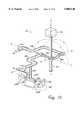
- a gimbal mechanismis coupled to the user object, such as a joystick or a medical tool, and provides at least two degrees of freedom to the user object, where the gimbal mechanism includes multiple members. A selected number of those members are segments formed as a unitary member which provides flex between the selected members.
- An actuatorapplies a force along a degree of freedom to the user object in response to electrical signals produced by the electrical system.
- a sensordetects a position of the user object along the degree of freedom and outputs sensor signals to the electrical system. The actuator and sensor thus provide an electromechanical interface between the user object and the electrical system.
- An actuatorprovides force to the user object along each degree of freedom, and the actuators are decoupled from each other.
- the gimbal mechanismpreferably provides at least two revolute degrees of freedom to the user object about axes of rotation.
- the gimbal mechanismcan provide at least two linear degrees of freedom along linear axes.
- the multiple members of the gimbal mechanismare formed as a closed-loop linkage.
- the linkagecan include four members that are flexibly coupled to each other as segments of the unitary member.
- the four membersinclude first and second extension members and first and second flexible central members, where the central members are each coupled to an extension member and to each other at the user object.
- a ground memberis coupled to a ground surface and is rotatably coupled to the unitary flexible member by bearings.
- Other embodimentsinclude coupling an object member to the user object and to the central members, and rotating the object member in a third "spin" degree of freedom, where the rotation in the third degree of freedom is allowed by the flexibility of the central members.
- the ends of the central membersare rotatably coupled to the extension members by bearings, and the central members are flexibly coupled to the user object.
- the ends of the central membersare flexibly coupled to the extension members and the central members are rotatably coupled to the user object by a bearing.
- a third central memberis flexibly coupled between one of the extension members and the user object.
- a linear axis membercan be coupled to the gimbal mechanism to provide the user object with a third linear degree of freedom.
- a passive damper elementcan also be coupled to at least one member of the gimbal mechanism to increase dynamic stability of the interface system.
- a capstan drive mechanismincluding a cable and pully, can used to transmit forces to and from the actuator/sensor and the user with no substantial backlash.
- the interface apparatusinterfaces the motion of the user object with the electrical system, which is a host computer.
- the host computer systemcan display images to the user on a display screen.
- a local microprocessorseparate from the host computer and controlled by software instructions, is used to communicate with the host computer via a communication interface by receiving a host command from the host computer.
- the actuatorapplies a force to the gimbal mechanism along a degree of freedom to the user object in accordance with a processor command received from the processor.
- the processor commandis derived from the host command.
- the sensordetects positions of the user object along a degree of freedom and outputs the sensor signals to the host computer system.
- the sensor signalsinclude information representative of the position of the user object.
- the senoris electrically coupled to the processor and outputs the sensor signals to the processor, and the processor sends the sensor signals to the host computer.
- the processorprovides the processor command to the actuator using a processor subroutine selected in accordance with the host command and stored in a memory device.
- the processoralso utilizes the sensor signals to help determine a force output by the actuator.
- the processorpreferably can use timing information from a clock coupled to the processor to determine the force output by the actuator.
- the communication interfacecan include a serial interface which, although relatively slow, may be used to provide accurate force feedback by using the local microprocessor.
- the actuators for applying forces to the user objectinclude voice coil actuators. These actuators apply a current to a wire coil within a magnetic field to produce a force on the coil and a moveable member to which the coil is attached. The produced force has a particular direction depending on the direction of a current flowed through said coil and a magnitude depending on the magnitude of the current.
- an electrical interfaceis electrically coupled between the voice coil actuators and the electrical system/host computer, and the electrical interface preferably includes a voice coil driver chip for driving the voice coil actuators.
- the voice coil driver chippreferably has a variable gain of voltage input to current output to provide more realistic and a greater range of forces.
- the wire coilincludes multiple sub-coils that each include a different number of loops. Constant magnitude currents can thus be flowed through selected sub-coils to create different force values on the user object.
- the voice coilmay includes one coil of wire to apply the force to the user object, and a second coil of wire used as a sensor for sensing a velocity of the user-manipulable object.
- the user objectis coupled to a planar member, such as a circuit board.
- the circuit boardis translatable in two degrees of freedom, and this translation causes the user object to move in two user object degrees of freedom.
- the user objectis coupled to a ball joint that is rotatable in a socket, such that translation of the circuit board causes the ball joint to rotate in the socket and thus causes the user object to pivot in two rotary two degrees of freedom.
- the user objectis coupled directly to the circuit board and is translated in linear degrees of freedom as the planar member is translated.
- the coils of wire included in the voice coil actuatorscan be etched onto the circuit board.
- the voice coil driver chips used for driving the voice coil actuators, and other electronic componentscan be included on the circuit board.
- the interface apparatusincludes a friction drive mechanism coupled between an actuator and a gimbal mechanism of the interface apparatus. Force from the actuator is transmitted to the gimbal mechanism through frictional contact of members of the friction drive mechanism.
- the friction drive mechanismpreferably includes a rotatable drum having a drive bar.
- a drive rolleris coupled to the actuator and frictionally engages the drive bar to rotate the drum and transmit a force to the object in a degree of freedom.
- one or more passive rollersare frictionally engaged with the drive bar on the opposite side of the drive bar to the drive roller, so that a greater compression force is provided between the drive roller and the drive bar.
- the passive rollerscan be spring loaded to the drive roller to provide greater compression force.
- a friction drive mechanismis provided for a second degree of freedom actuator as well.
- the friction drive mechanismincludes a translatable drum having a drive bar, where the drive roller frictionally engages the drive bar to translate the drum and apply a linear force to the object in a linear degree of freedom.
- the interface apparatus of the present inventionincludes several low cost components that are suitable for providing accurate force feedback for the home market and other markets.
- the flexible unitary member of the preferred gimbal mechanismcan be produced as one part without incurring expenses for bearings and assembly procedures.
- the embodiments of the present invention including the voice coil actuatorsutilize readily-available, cheap components that are able to produce realistic forces for the user.
- the friction drive mechanism of the present inventionis able to transmit forces and provide mechanical advantage using low cost parts.
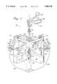
- FIG. 1is a perspective view of a virtual reality system which employs an apparatus of the present invention to interface a laparoscope tool handle with a computer system;
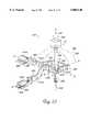
- FIG. 2is a perspective view of a mechanical apparatus of the present invention for providing mechanical input and output to a computer system
- FIG. 3is a perspective front view of a preferred embodiment of the mechanical apparatus of FIG. 2;
- FIG. 4is a perspective rear view of the embodiment of the mechanical apparatus of FIG. 3;
- FIG. 5is a perspective detailed view of a capstan drive mechanism used for two degrees of motion in the present invention.
- FIG. 5ais a side elevational view of the capstan drive mechanism shown in FIG. 5;
- FIG. 5bis a detailed side view of a pulley and cable of the capstan drive mechanism of FIG. 5;
- FIG. 6is a perspective view of a center capstan drive mechanism for a linear axis member of the mechanical apparatus shown in FIG. 3;
- FIG. 6ais a cross sectional top view of a pulley and linear axis member used in the capstan drive mechanism of FIG. 6;
- FIG. 6bis a cross sectional side view of the linear axis member and transducer shown in FIG. 6;
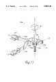
- FIG. 7is a perspective view of an embodiment of the apparatus of FIG. 2 having a stylus object for the user;
- FIG. 8is a perspective view of an embodiment of the apparatus of FIG. 2 having a joystick object for the user;
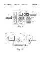
- FIG. 9is a block diagram of a computer and the interface between the computer and the mechanical apparatus of FIG. 2;
- FIG. 10is a schematic diagram of a suitable circuit for a digital to analog controller of the interface of FIG. 9;
- FIG. 11is a schematic diagram of a suitable power amplification circuit for powering the actuators of the present invention as shown in FIG. 9;
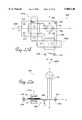
- FIG. 12is a perspective view of an alternate embodiment of the mechanical apparatus of FIG. 2 including flexible members;
- FIG. 13is a top plan view of the mechanical apparatus of FIG. 12;
- FIG. 14is a perspective view of a second alternate embodiment of the mechanical apparatus of FIG. 12;
- FIG. 15is a perspective view of a third alternate embodiment of the mechanical apparatus of FIG. 12;
- FIG. 16is a perspective view of a fourth alternate embodiment of the mechanical apparatus of FIG. 12;
- FIG. 17is a perspective view of a fifth alternate embodiment of the mechanical apparatus of FIG. 12;
- FIG. 18is a perspective view of the mechanical apparatus of FIG. 2 including a voice coil actuator
- FIG. 19ais a side sectional view of the voice coil actuator of FIG. 18;
- FIG. 19bis a top plan view of the voice coil actuator of FIG. 19a;
- FIGS. 20a-20eare schematic diagrams of an alternate embodiment of the voice coil actuator of FIG. 19a;
- FIG. 21ais a perspective view of an interface apparatus of the present invention including linear voice coil actuators
- FIG. 21bis a side sectional view showing a linear voice coil actuator of FIG. 21a;
- FIG. 21cis a perspective view of an alternate embodiment of the interface apparatus of FIG. 21a;
- FIG. 22ais a top plan view of an interface apparatus of the present invention having linear voice coil actuators on a circuit board and in which the user object can be moved in rotary degrees of freedom;
- FIG. 22bis a side elevational view of the interface apparatus of FIG. 22a;
- FIG. 22cis a top plan view of an alternate embodiment of the interface apparatus of FIG. 22a using a different anti-rotation flexure;
- FIG. 22dis a top plan view of an alternate embodiment of the interface apparatus of FIG. 22a in which the user object can be moved in linear degrees of freedom;
- FIG. 22eis a side elevational view of the interface apparatus of FIG. 22c;
- FIGS. 23a to 23fare side elevational views of a friction drive of the present invention suitable for use with the interface apparatus of the present invention.
- FIG. 24is a block diagram of a host computer and an alternative embodiment of the electronic interface between the computer and an interface apparatus of the present invention.
- FIG. 1illustrates an example of the use of the present invention for medical simulation purposes.
- a virtual reality system 10 used to simulate a medical procedureincludes a human/computer interface apparatus 12, an electronic interface 14, and a host computer 16.
- the illustrated virtual reality system 10is directed to a virtual reality simulation of a laparoscopic surgery procedure.
- the handle 26 of a laparoscopic tool 18 used in conjunction with the present inventionis manipulated by an operator and virtual reality images are displayed on a display screen 20 of the digital processing system in response to such manipulations.
- Display screen 20can be a standard display screen or CRT, 3-D goggles, or any other visual interface.
- the digital processing systemis typically a host computer 16.
- the host computeris a personal computer or workstation, such as an IBM-PC AT or Macintosh personal computer, or a SUN or Silicon Graphics workstation.
- the computer 16can operate under the MS-DOS operating system in conformance with an IBM PC AT standard.
- host computer system 12can be one of a variety of home video game systems commonly connected to a television set, such as systems available from Nintendo, Sega, or Sony.
- home computer system 12can be a "set top box" which can be used, for example, to provide interactive television functions to users.
- Host computer 16implements a host application program with which a user is interacting via peripherals and interface device 14.
- the host application programcan be a video game, medical simulation, scientific analysis program, or even an operating system or other application program that utilizes force feedback.
- the host applicationprovides images to be displayed on a display output device, as described below, and/or other feedback, such as auditory signals.
- the medical simulation example of FIG. 1includes a host medical simulation application program.
- Such softwareis commercially available as, for example, TeleosTM from High Techsplanations of Rockville, Md. Suitable software drivers which interface such simulation software with computer input/output (I/O) devices are available from Immersion Human Interface Corporation of Santa Clara, Calif.
- display screen 20can display images from a game application program. For example, images describing a point of view from a first-person perspective can be displayed, as in a virtual reality game. Or, images describing a third-person perspective of objects, backgrounds, etc. can be displayed.
- a human/interface apparatus 12as illustrated herein is used to simulate a laparoscopic medical procedure.
- the human/interface apparatus 12may include a barrier 22 and a standard laparoscopic trocar 24 (or a facsimile of a trocar).
- the barrier 22is used to represent portion of the skin covering the body of a patient.
- Trocar 24is inserted into the body of the virtual patient to provide an entry and removal point from the body of the patient for the laparoscopic tool 18, and to allow the manipulation of the laparoscopic tool.
- Laparoscopic tools and trocars 24are commercially available from sources such as U.S. Surgical of Connecticut. Barrier 22 and trocar 24 can be omitted from apparatus 12 in other embodiments.
- the laparoscopic tool 18is modified; in the preferred embodiment, the shaft is replaced by a linear axis member of the present invention, as described below.
- the end of the shaft of the tool(such as any cutting edges) can be removed.
- the end of the laparoscopic tool 18is not required for the virtual reality simulation, and is removed to prevent any potential damage to persons or property.
- the laparoscopic tool 18includes a handle or "grip" portion 26 and a shaft portion 28.
- the shaft portionis an elongated mechanical object and, in particular, is an elongated cylindrical object, described in greater detail below.
- the present inventionis concerned with tracking the movement of the shaft portion 28 in three-dimensional space, where the movement has been constrained such that the shaft portion 28 has only three or four free degrees of motion. This is a good simulation of the real use of a laparoscopic tool 18 in that once it is inserted into a trocar 24 and through the mechanical apparatus 25, it is limited to about four degrees of freedom. More particularly, the shaft 28 is constrained at some point of along its length such that it can move with four degrees of freedom within the patient's body.
- a mechanical apparatus 25 for interfacing mechanical input and outputis shown within the "body" of the patient in phantom lines.
- the computerwill send feedback signals to the tool 18 and mechanical apparatus 25, which has actuators for generating forces in response to the position of a virtual laparoscopic tool relative to the surface depicted on the computer screen. Force is applied for example, by powering the actuators appropriate to the images portrayed on the screen.
- Mechanical apparatus 25is shown in greater detail with respect to FIGS. 2 and 12.
- the present inventioncan be used with any mechanical object where it is desirable to provide a human/computer interface with one to six degrees of freedom.
- Such objectsmay include endoscopic or other similar surgical tools used in medical procedures, catheters, hypodermic needles, wires, fiber optic bundles, styluses, joysticks, screw drivers, pool cues, etc.
- the electronic interface 14is a component of the human/computer interface apparatus 12 and may couple the apparatus 12 to the host computer 16.
- Electronic interface 14can be included within a housing of mechanical apparatus 25 or be provided as a separate unit, as shown in FIG. 1. More particularly, interface 14 is used in preferred embodiments to couple the various actuators and sensors of apparatus 25 (described in detail below) to computer 16.
- One suitable embodiment of interface 14is described in detail with reference to FIG. 9, in which the interface can include a dedicated interface card to be plugged into computer 16.
- a different embodiment 14' of interface 14is described in detail with respect to FIG. 20, in which the interface includes a microprocessor local to the apparatus 12 and can be coupled to computer 16 through a slower, serial interface or a parallel interface.
- the electronic interface 14can be coupled to mechanical apparatus 25 of the apparatus 12 by a cable 30 (or may be included within the housing of apparatus 12) and is coupled to the computer 16 by a cable 32 (or may be directly connected to the computer using a interface card). In other embodiments, signals can be sent to and from interface 14 and computer 16 by wireless transmission and reception. In some embodiments of the present invention, interface 14 serves solely as an input device for the computer 16. In other embodiments of the present invention, interface 14 serves solely as an output device for the computer 16. In preferred embodiments of the present invention, the interface 14 serves as an input/output (I/O) device for the computer 16. The interface 14 can also receive inputs from other input devices or controls that are associated with apparatus 12 and can relay those inputs to computer 16. For example, commands sent by the user activating a button on apparatus 12 can be relayed to computer 16 to implement a command or cause the computer 16 to output a command to the apparatus 12. Such input devices are described in greater detail with respect to FIG. 24.
- FIG. 2a perspective view of mechanical apparatus 25 for providing mechanical input and output in accordance with the present invention is shown.
- Apparatus 25includes a gimbal mechanism 38 and a linear axis member 40.
- a user object 44is preferably coupled to linear axis member 40.
- Gimbal mechanism 38in the described embodiment, provides support for apparatus 25 on a grounded surface 56 (schematically shown as part of member 46).
- Gimbal mechanism 38is preferably a five-member linkage that includes a ground member 46, extension members 48a and 48b, and central members 50a and 50b.
- Ground member 46is coupled to a base or surface which provides stability for apparatus 25.
- Ground member 46is shown in FIG. 2 as two separate members coupled together through grounded surface 56.
- the members of gimbal mechanism 38are rotatably coupled to one another through the use of rotatable bearings or pivots, wherein extension member 48a is rotatably coupled to ground member 46 by bearing 43a and can rotate about an axis A, central member 50a is rotatably coupled to extension member 48a by bearing 45a and can rotate about a floating axis D, extension member 48b is rotatably coupled to ground member 46 by bearing 43b and can rotate about axis B, central member 50b is rotatably coupled to extension member 48b by bearing 45b and can rotate about floating axis E, and central member 50a is rotatably coupled to central member 50b by bearing 47 at a center point P at the intersection of axes D and E.
- central member 50ais coupled to one rotatable portion 47a of bearing 47
- central member 50bis coupled to the other rotatable portion 47b of bearing 47.
- the axes D and Eare "floating" in the sense that they are not fixed in one position as are axes A and B.
- Axes A and Bare substantially mutually perpendicular.
- substantially perpendicularwill mean that two objects or axis are exactly or almost perpendicular, i.e. at least within five degrees or ten degrees of perpendicular, or more preferably within less than one degree of perpendicular.
- substantially parallelwill mean that two objects or axis are exactly or almost parallel, i.e. are at least within five or ten degrees of parallel, and are preferably within less than one degree of parallel.
- Gimbal mechanism 38is formed as a five member closed chain. Each end of one member is coupled to the end of a another member.
- the five-member linkageis arranged such that extension member 48a, central member 50a, and central member 50b can be rotated about axis A in a first degree of freedom.
- the linkageis also arranged such that extension member 48b, central member 50b, and central member 50a can be rotated about axis B in a second degree of freedom.
- an angle ⁇ between the central members 50a and 50bis about 90 degrees.
- central membersmove in two fashions: rotation about axis D or E by bearing 45b and/or 45a, and rotation about axis C by bearing 47 such that angle ⁇ changes. For example, if the object 44 is moved into the page of FIG. 2 away from the viewer, or out of the plane of the page toward the viewer, then the angle ⁇ will decrease. If the object is moved to the left or right as shown in FIG. 2, the angle ⁇ will increase.
- Linear axis member 40is preferably an elongated rod-like member which is coupled to central member 50a and central member 50b at the point of intersection P of axes A and B. As shown in FIG. 1, linear axis member 40 can be used as shaft 28 of user object 44. In other embodiments, linear axis member 40 is coupled to a different object. Linear axis member 40 is coupled to gimbal mechanism 38 such that it extends out of the plane defined by axis A and axis B. Linear axis member 40 can be rotated about axis A by rotating extension member 48a, central member 50a, and central member 50b in a first revolute degree of freedom, shown as arrow line 51.
- Member 40can also be rotated about axis B by rotating extension member 50b and the two central members about axis B in a second revolute degree of freedom, shown by arrow line 52. Being also translatably coupled to the ends of central members 50a and 50b, linear axis member 40 can be linearly translated, independently with respect to the gimbal mechanism 38, along floating axis C, providing a third degree of freedom as shown by arrows 53.
- Axis Ccan, of course, be rotated about one or both axes A and B as member 40 is rotated about these axes.
- transducerssuch as sensors and actuators.
- Such transducersare preferably coupled at the link points between members of the apparatus and provide input to and output from an electrical system, such as computer 16.
- Transducers that can be used with the present inventionare described in greater detail with respect to FIG. 3.
- User object 44is coupled to apparatus 25 and is preferably an interface object for a user to grasp or otherwise manipulate in three dimensional (3D) space.
- a user object 44is the grip 26 of a laparoscopic tool 18, as shown in FIG. 1.
- Shaft 28 of tool 18can be implemented as part of linear axis member 40.
- Other examples described in subsequent embodimentsinclude a stylus and joystick.
- User object 44may be moved in all three degrees of freedom provided by gimbal mechanism 38 and linear axis member 40 and additional degrees of freedom as described below.
- floating axis Dvaries its position
- floating axis Efloating axis E varies its position.
- the floating axes E and Dare coincident with the fixed axes A and B, respectively, when the user object is in a center position as shown in FIG. 2.
- FIGS. 3 and 4are perspective views of a specific embodiment of a mechanical apparatus 25' for providing mechanical input and output to a computer system in accordance with the present invention.
- FIG. 3shows a front view of apparatus 25'
- FIG. 4shows a rear view of the apparatus.
- Apparatus 25'includes a gimbal mechanism 38, a linear axis member 40, and transducers 42.
- a user object 44shown in this embodiment as a laparoscopic instrument having a grip portion 26, is coupled to apparatus 25'.
- Apparatus 25'operates in substantially the same fashion as apparatus 25 described with reference to FIG. 2.
- Gimbal mechanism 38provides support for apparatus 25' on a grounded surface 56, such as a table top or similar surface.
- the members and joints ("bearings") of gimbal mechanism 38are preferably made of a lightweight, rigid, stiff metal, such as aluminum, but can also be made of other rigid materials such as other metals, plastic, etc.
- Gimbal mechanism 38includes a ground member 46, capstan drive mechanisms 58, extension members 48a and 48b, central drive member 50a, and central link member 50b.
- Ground member 46includes a base member 60 and vertical support members 62.
- Base member 60is coupled to grounded surface 56 and provides two outer vertical surfaces 61 which are in a substantially perpendicular relation which each other.
- a vertical support member 62is coupled to each of these outer surfaces of base member 60 such that vertical members 62 are in a similar substantially 90-degree relation with each other.
- a capstan drive mechanism 58is preferably coupled to each vertical member 62. Capstan drive mechanisms 58 are included in gimbal mechanism 38 to provide mechanical advantage without introducing friction and backlash to the system. A capstan drum 59 of each capstan drive mechanism is rotatably coupled to a corresponding vertical support member 62 to form axes of rotation A and B, which correspond to axes A and B as shown in FIG. 1. The capstan drive mechanisms 58 are described in greater detail with respect to FIG. 5.
- Extension member 48ais rigidly coupled to capstan drum 59 and is rotated about axis A as capstan drum 59 is rotated.
- extension member 48bis rigidly coupled to the other capstan drum 59 and can be rotated about axis B. Both extension members 48a and 48b are formed into a substantially 90-degree angle with a short end 49 coupled to capstan drum 59.
- Central drive member 50ais rotatably coupled to a long end 55 of extension member 48a and extends at a substantially parallel relation with axis B.
- central link member 50bis rotatably coupled to the long end of extension member 48b and extends at a substantially parallel relation to axis A (as better viewed in FIG. 4).
- Central drive member 50a and central link member 50bare rotatably coupled to each other at the center of rotation of the gimbal mechanism, which is the point of intersection P of axes A and B.
- Bearing 64connects the two central members 50a and 50b together at the intersection point P.
- Gimbal mechanism 38provides two degrees of freedom to an object positioned at or coupled to the center point P of rotation.
- An object at or coupled to point Pcan be rotated about axis A and B or have a combination of rotational movement about these axes.
- Linear axis member 40is a cylindrical member that is preferably coupled to central members 50a and 50b at intersection point P.
- linear axis member 40can be a non-cylindrical member having a cross-section of, for example, a square or other polygon.
- Member 40is positioned through the center of bearing 64 and through holes in the central members 50a and 50b.
- the linear axis membercan be linearly translated along axis C, providing a third degree of freedom to user object 44 coupled to the linear axis member.
- Linear axis member 40can preferably be translated by a transducer 42 using a capstan drive mechanism similar to capstan drive mechanism 58. The translation of linear axis member 40 is described in greater detail with respect to FIG. 6.
- Transducers 42are preferably coupled to gimbal mechanism 38 to provide input and output signals between mechanical apparatus 25' and computer 16.
- transducers 42include two grounded transducers 66a and 66b, central transducer 68, and shaft transducer 70.
- the housing of grounded transducer 66ais preferably coupled to vertical support member 62 and preferably includes both an actuator for providing force in or otherwise influencing the first revolute degree of freedom about axis A and a sensor for measuring the position of object 44 in or otherwise influenced by the first degree of freedom about axis A, i.e., the transducer 66a is "associated with" or "related to" the first degree of freedom.
- a rotational shaft of actuator 66ais coupled to a pulley of capstan drive mechanism 58 to transmit input and output along the first degree of freedom.
- the capstan drive mechanism 58is described in greater detail with respect to FIG. 5.
- Grounded transducer 66bpreferably corresponds to grounded transducer 66a in function and operation.
- Transducer 66bis coupled to the other vertical support member 62 and is an actuator/sensor which influences or is influenced by the second revolute degree of freedom about axis B.
- Grounded transducers 66a and 66bare preferably bi-directional transducers which include sensors and actuators.
- the sensorsare preferably relative optical encoders which provide signals to measure the angular rotation of a shaft of the transducer.
- the electrical outputs of the encodersare routed to computer interface 14 via buses 67a and 67b and are detailed with reference to FIG. 9.
- Other types of sensorscan also be used, such as potentiometers, etc.
- a Polhemus (magnetic) sensorcan detect magnetic fields from objects; or, an optical sensor such as lateral effect photo diode includes a emitter/detector pair that detects positions of the emitter with respect to the detector in one or more degrees of freedom; for example, a photo diode by Hamamatsu Co., part S1743, can be used.
- sensorsare able to detect the position of object 44 in particular degrees of freedom without having to be coupled to a joint of the mechanical apparatus.
- sensorscan be positioned at other locations of relative motion or joints of mechanical apparatus 25.
- an absolute sensoris one which the angle of the sensor is known in absolute terms, such as with an analog potentiometer.
- Relative sensorsonly provide relative angle information, and thus require some form of calibration step which provide a reference position for the relative angle information.
- the sensors described hereinare primarily relative sensors. In consequence, there is an implied calibration step after system power-up wherein the sensor's shaft is placed in a known position within the apparatus 25' and a calibration signal is provided to the system to provide the reference position mentioned above. All angles provided by the sensors are thereafter relative to that reference position.
- Such calibration methodsare well known to those skilled in the art and, therefore, will not be discussed in any great detail herein.
- Transducers 66a and 66balso preferably include actuators. These actuators can be of two types: active actuators and passive actuators. Active actuators include linear current control motors, stepper motors, pneumatic/hydraulic active actuators, and other types of actuators that transmit a force to move an object. For example, active actuators can drive a rotational shaft about an axis in a rotary degree of freedom, or drive a linear shaft along a linear degree of freedom. Active transducers of the present invention are preferably bi-directional, meaning they can selectively transmit force along either direction of a degree of freedom. For example, DC servo motors can receive force control signals to control the direction and torque (force output) that is produced on a shaft.
- active linear current control motorssuch as DC servo motors
- the control signals for the motorare produced by computer interface 14 on control buses 67a and 67b and are detailed with respect to FIG. 9.
- the motorsmay include brakes which allow the rotation of the shaft to be halted in a short span of time.
- the sensors and actuators in transducers 42can be included together as a sensor/actuator pair transducers.
- a suitable transducer for the present invention including both an optical encoder and current controlled motoris a 20 W basket wound servo motor manufactured by Maxon.
- stepper motorscan also be used, such as a stepper motor, brushless DC motors, pneumatic/hydraulic actuators, a torquer (motor with limited angular range), or a voice coil, which are well known to those skilled in the art.
- Voice coilsare described in greater detail with respect to FIG. 18. Stepper motors and the like are not as well suited because stepper motor control involves the use of steps or pulses which can be felt as pulsations by the user, thus corrupting the virtual simulation.
- the present inventionis better suited to the use of linear current controlled motors, which do not have this noise.
- Passive actuatorscan also be used in transducers 66a, 66b, and 68. Magnetic particle brakes, friction brakes, or pneumatic/hydraulic passive actuators can be used in addition to or instead of a motor to generate a damping resistance or friction in a degree of motion.
- An alternate preferred embodiment only including passive actuatorsmay not be as realistic as an embodiment including motors; however, the passive actuators are typically safer for a user since the user does not have to fight generated forces.
- Passive actuatorstypically can only provide bi-directional resistance to a degree of motion.
- a suitable magnetic particle brake for interface device 14is available from Force Limited, Inc. of Santa Monica, Calif.
- transducers 42can include only sensors to provide an apparatus without force feedback along designated degrees of freedom. Similarly, all or some of transducers 42 can be implemented as actuators without sensors to provide only force feedback.
- passive damper elementscan be provided on the bearings of apparatus 25 to remove energy from the system and intentionally increase the dynamic stability of the mechanical system. This may have the side effect of degrading the bandwidth of the system; however, if other factors such as the speed of processor 410 (see FIG. 24), rate of actuator control, and position sensing resolution already degrade the bandwidth, then such dampers may be acceptable.
- inexpensive plastic damperssuch as rotational dampers produced by Fastex/Deltar, can be placed at desired bearing positions and have one end grounded.
- this passive dampingcan be introduced by using the back electromotive force (EMF) of the actuators 42 to remove energy from the system.
- EMFback electromotive force
- Central transducer 68is coupled to central drive member 50a and preferably includes an actuator for providing force in the linear third degree of freedom along axis C and a sensor for measuring the position of object 44 along the third degree of freedom.
- the rotational shaft of central transducer 68is coupled to a translation interface coupled to central drive member 50a which is described in greater detail with respect to FIG. 6.
- central transducer 68is an optical encoder and DC servo motor combination similar to the actuators 66a and 66b described above.
- the transducers 66a, 66b and 68 of the described embodimentare advantageously positioned to provide a very low amount of inertia to the user handling object 44.
- Transducer 66a and transducer 66bare decoupled, meaning that the transducers are both directly coupled to ground member 46 which is coupled to ground surface 56, i.e. the ground surface carries the weight of the transducers, not the user handling object 44.
- the weights and inertia of the transducers 66a and 66bare thus substantially negligible to a user handling and moving object 44. This provides a more realistic interface to a virtual reality system, since the computer can control the transducers to provide substantially all of the forces felt by the user in these degrees of motion.
- Apparatus 25'is a high bandwidth force feedback system, meaning that high frequency signals can be used to control transducers 42 and these high frequency signals will be applied to the user object with high precision, accuracy, and dependability. The user feels very little compliance or "mushiness" when handling object 44 due to the high bandwidth.
- one actuator"rides” upon another actuator in a serial chain of links and actuators. This low bandwidth arrangement causes the user to feel the inertia of coupled actuators when manipulating an object.
- Central transducer 68is positioned near the center of rotation of two revolute degrees of freedom. Though the transducer 68 is not grounded, its central position permits a minimal inertial contribution to the mechanical apparatus 25' along the provided degrees of freedom. A user manipulating object 44 thus will feel minimal internal effects from the weight of transducers 66a, 66b and 68.
- Shaft transducer 70preferably includes a sensor and is provided in the described embodiment to measure a fourth degree of freedom for object 44.
- Shaft transducer 70is preferably positioned at the end of linear axis member 40 that is opposite to the object 44 and measures the rotational position of object 44 about axis C in the fourth degree of freedom, as indicated by arrow 72.
- Shaft transducer 70is described in greater detail with respect to FIG. 6 and 6b.
- shaft transducer 72is implemented using an optical encoder similar to the encoders described above.
- a suitable input transducer for use in the present inventionis an optical encoder model SI marketed by U.S. Digital of Vancouver, Wash.
- shaft transducer 70only includes a sensor and not an actuator.
- an actuatorsuch as a motor can be included in shaft transducer 70 similar to transducers 66a, 66b, and 68.
- Object 44is shown in FIGS. 3 and 4 as a grip portion 26 of a laparoscopic tool similar to the tool shown in FIG. 1.
- Shaft portion 28is implemented as linear axis member 40.
- a usercan move the laparoscopic tool about axes A and B, and can translate the tool along axis C and rotate the tool about axis C. The movements in these four degrees of freedom will be sensed and tracked by computer system 16. Forces can be applied preferably in the first three degrees of freedom by the computer system to simulate the tool impacting a portion of subject body, experiencing resistance moving through tissues, etc.
- additional transducerscan be added to apparatus 25' to provide additional degrees of freedom for object 44.
- a transducercan be added to grip 26 of laparoscopic tool 18 to sense when the user moves the two portions 26a and 26b relative to each other to simulate extending the cutting blade of the tool.
- Such a laparoscopic tool sensoris described in U.S. Pat. No. 5,623,582, filed Jul. 14, 1994 and entitled "Method and Apparatus for Providing Mechanical I/O for Computer Systems" assigned to the assignee of the present invention and incorporated herein by reference in its entirety.
- FIG. 5is a perspective view of a capstan drive mechanism 58 shown in some detail.
- the drive mechanism 58 coupled to extension arm 48bis shown; the other capstan drive 58 coupled to extension arm 48a is substantially similar to the mechanism presented here.
- Capstan drive mechanism 58includes capstan drum 59, capstan pulley 76, and stop 78.
- Capstan drum 59is preferably a wedge-shaped member having leg portion 82 and a curved portion 84. Other shapes of member 59 can also be used.
- Leg portion 82is pivotally coupled to vertical support member 62 at axis B (or axis A for the opposing capstan drive mechanism).
- Extension member 48bis rigidly coupled to leg portion 82 such that when capstan drum 59 is rotated about axis B, extension member 48b is also rotated and maintains the position relative to leg portion 82 as shown in FIG. 5.
- Curved portion 84couples the two ends of leg portion 82 together and is preferably formed in an arc centered about axis B. Curved portion 84 is preferably positioned such that its bottom edge 86 is about 0.030 inches above pulley 76.
- Cable 80is preferably a thin metal cable connected to curved portion 84 of the capstan drum. Other types of durable cables, cords, wire, etc. can be used as well. Cable 80 is attached at a first end to curved portion 84 near an end of leg portion 82 and is drawn tautly against the outer surface 86 of curved portion 84. Cable 80 is wrapped around pulley 76 a number of times and is then again drawn tautly against outer surface 86. The second end of cable 80 is firmly attached to the other end of curved portion 84 near the opposite leg of leg portion 82. The cable transmits rotational force from pulley 76 to the capstan drum 59, causing capstan drum 59 to rotate about axis B as explained below.
- the cablealso transmits rotational force from drum 59 to the pulley and transducer 66b.
- the tension in cable 80should be at a level so that negligible backlash or play occurs between capstan drum 59 and pulley 76.
- the tension of cable 80can be adjusted by pulling more (or less) cable length through an end of curved portion 84.
- Caps 81 on the ends of curved portion 84can be used to easily tighten cable 80.
- Each cap 81is preferably tightly coupled to cable 80 and includes a pivot and tightening screw which allow the cap to move in a direction indicated by arrow 83 to tighten cable 80.
- Capstan pulley 76is a threaded metal cylinder which transfers rotational force from transducer 66b to capstan drum 59 and from capstan drum 59 to transducer 66b.
- Pulley 76is rotationally coupled to vertical support member 62 by a shaft 88 (shown in FIG. 5a) positioned through a bore of vertical member 62 and rigidly attached to pulley 76.
- Transducer 66bis coupled to pulley 76 by shaft 88 through vertical support member 62. Rotational force is applied from transducer 66b to pulley 76 when the actuator of transducer 66b rotates the shaft.
- the pulleytransmits the rotational force to cable 80 and thus forces capstan drum 59 to rotate in a direction about axis B.
- Extension member 48brotates with capstan drum 59, thus causing force along the second degree of freedom for object 44.
- pulley 76, capstan drum 59 and extension member 48bwill only actually rotate if the user is not applying the same amount or a greater amount of rotational force to object 44 in the opposite direction to cancel the rotational movement. In any event, the user will feel the rotational force along the second degree of freedom in object 44 as force feedback.
- the capstan mechanism 58provides a mechanical advantage to apparatus 25' so that the force output of the actuators can be increased.
- the ratio of the diameter of pulley 76 to the diameter of capstan drum 59dictates the amount of mechanical advantage, similar to a gear system.
- the ratio of drum to pulleyis equal to 15:1, although other ratios can be used in other embodiments.
- extension member 48brotates about axis B and rotates capstan drum 59 about axis B as well.
- This movementcauses cable 80 to move, which transmits the rotational force to pulley 76.
- Pulley 76rotates and causes shaft 88 to rotate, and the direction and magnitude of the movement is detected by the sensor of transducer 66b.
- a similar processoccurs along the first degree of freedom for the other capstan drive mechanism 58.
- the capstan drive mechanismprovides a mechanical advantage to amplify the sensor resolution by a ratio of drum 59 to pulley 76 (15:1 in the preferred embodiment).
- Stop 78is rigidly coupled to vertical support member 62 a few millimeters above curved portion 84 of capstan drum 59. Stop 78 is used to prevent capstan drum 59 from moving beyond a designated angular limit. Thus, drum 59 is constrained to movement within a range defined by the arc length between the ends of leg portion 82. This constrained movement, in turn, constrains the movement of object 44 in the first two degrees of freedom.
- stop 78is a cylindrical member inserted into a threaded bore in vertical support member 62.
- FIG. 5ais a side elevational view of capstan mechanism 58 as shown in FIG. 5.
- Cable 80is shown routed along the bottom side 86 of curved portion 84 of capstan drum 59.
- Cable 80is preferably wrapped around pulley 76 so that the cable is positioned between threads 90, i.e., the cable is guided by the threads as shown in greater detail in FIG. 5b.
- the portion of cable 80 wrapped around the pulleytravels closer to or further from vertical support member 62, depending on the direction that pulley 76 rotates. For example, if pulley 76 is rotated counterclockwise (when viewing the pulley as in FIG.
- pulley 76are used mainly to provide cable 80 with a better grip on pulley 76.
- pulley 76includes no threads, and the high tension in cable 80 allows cable 80 to grip pulley 76.
- Capstan drive mechanism 58is advantageously used in the present invention to provide transmission of forces and mechanical advantage between transducers 66a and 66b and object 44 without introducing substantial compliance, friction, or backlash to the system.
- a capstan driveprovides increased stiffness, so that forces are transmitted with negligible stretch and compression of the components. The amount of friction is also reduced with a capstan drive mechanism so that substantially “noiseless” tactile signals can be provided to the user.
- the amount of backlash contributed by a capstan driveis also negligible. "Backlash” is the amount of play that occurs between two coupled rotating objects in a gear or pulley system.
- gears, belts, or other types of drive mechanismscould also be used in place of capstan drive mechanism 58 in alternate embodiments to transmit forces between transducer 66a and extension member 48b.
- gears and the liketypically introduce some backlash in the system.
- a usermight be able to feel the interlocking and grinding of gear teeth during rotation of gears when manipulating object 44; the rotation in a capstan drive mechanism is much less noticeable.
- FIG. 6is a perspective view of central drive member 50a and linear axis member 40 shown in some detail.
- Central drive member 50ais shown in a partial cutaway view to expose the interior of member 50a.
- Central transducer 68is coupled to one side of central drive member 50a.
- a capstan drive mechanismis used to transmit forces between transducer 68 and linear axis member 40 along the third degree of freedom.
- a rotatable shaft 98 of transducer 68extends through a bore in the side wall of central drive member 50a and is coupled to a capstan pulley 100. Pulley 100 is described in greater detail below with respect to FIG. 6a.
- Linear axis member 40preferably includes an exterior sleeve 91 and an interior shaft 93 (described with reference to FIG. 6b, below).
- Exterior sleeve 91is preferably a partially cylindrical member having a flat 41 provided along its length. Flat 41 prevents sleeve 91 from rotating about axis C in the fourth degree of freedom described above.
- Linear axis member 40is provided with a cable 99 which is secured on each end of member 40 by tension caps 101. Cable 99 preferably runs down a majority of the length of exterior sleeve 91 on the surface of flat 41 and can be tightened, for example, by releasing a screw 97, pulling an end of cable 99 until the desired tension is achieved, and tightening screw 97. Similarly to the cable of the capstan mechanism described with reference to FIG. 5, cable 99 should have a relatively high tension.
- Pulley 100preferably includes a central axle portion 103 and end lip portions 105. Exterior sleeve 91 is preferably positioned such that flat 41 of the sleeve is touching or is very close to lip portions 105 on both sides of axle portion 103.
- the cable 99 portion around pulley 100is wrapped around central axle portion 103 and moves along portion 103 towards and away from shaft 98 as the pulley is rotated clockwise and counterclockwise, respectively.
- the diameter of axle portion 103is smaller than lip portion 105, providing space between the pulley 100 and flat 41 where cable 99 is attached and allowing free movement of the cable.
- Pulley 100preferably does not include threads, unlike pulley 76, since the tension in cable 99 allows the cable to grip pulley 100 tightly.
- pulley 100can be a threaded or unthreaded cylinder similar to capstan pulley 76 described with reference to FIG. 5.
- transducer 68can translate linear axis member 40 along axis C when the pulley is rotated by the actuator of transducer 68. Likewise, when linear axis member 40 is translated along axis C by the user manipulating object 44, pulley 100 and shaft 98 are rotated; this rotation is detected by the sensor of transducer 68.
- the capstan drive mechanismprovides low friction and smooth, rigid operation for precise movement of linear axis member 40 and accurate position measurement of the member 40.
- a drive wheelmade of a rubber-like material or other frictional material can be positioned on shaft 98 to contact linear axis member 40 along the edge of the wheel. The wheel can cause forces along member 40 from the friction between wheel and linear axis member.
- a drive wheel mechanismis disclosed in the abovementioned Pat. No. 5,623,582 as well as in U.S. Patent application Ser. No. 08/344,148, filed Nov.
- Linear axis member 40can also be a single shaft in alternate embodiments instead of a dual part sleeve and shaft.
- interior shaft 93is positioned inside hollow exterior sleeve 91 and is rotatably coupled to sleeve 91.
- a first end 107 of shaft 93preferably extends beyond sleeve 91 and is coupled to object 44.
- shaft 93is also rotated about axis C in the fourth degree of freedom within sleeve 91.
- Shaft 93is translated along axis C in the third degree of freedom when sleeve 91 is translated.
- interior shaft 93can be coupled to a shaft of object 44 within exterior sleeve 91.
- a short portion of shaft 28 of laparoscopic tool 18, as shown in FIG. 1,can extend into sleeve 91 and be coupled to shaft 93 within the sleeve, or shaft 28 can extend all the way to transducer 70 and functionally be used as shaft 93.
- Shaft 93is coupled at its second end 109 to transducer 70, which, in the preferred embodiment, is an optical encoder sensor.
- the housing 111 of transducer 70is rigidly coupled to exterior sleeve 91 by a cap 115, and a shaft 113 of transducer 70 is coupled to interior shaft 93 so that transducer 70 can measure the rotational position of shaft 93 and object 44.
- an actuatorcan also be included in transducer 70 to provide rotational forces about axis C to shaft 93.
- FIG. 7is a perspective view of an alternate embodiment of the mechanical apparatus 25" and user object 44 of the present invention.
- Mechanical apparatus 25" shown in FIG. 7operates substantially the same as apparatus 25' shown in FIGS. 3 and 4.
- User object 44is a stylus 102 which the user can grasp and move in six degrees of freedom.
- “grasp”it is meant that users may releasably engage a grip portion of the object in some fashion, such as by hand, with their fingertips, or even orally in the case of handicapped persons.
- Stylus 102can be sensed and force can be applied in various degrees of freedom by a computer system and interface such as computer 16 and interface 14 of FIG. 1.
- Stylus 102can be used in virtual reality simulations in which the user can move the stylus in 3D space to point to objects, write words, drawings, or other images, etc.
- a usercan view a virtual environment generated on a computer screen or in 3D goggles.
- a virtual styluscan be presented in a virtual hand of the user.
- the computer systemtracks the position of the stylus with sensors as the user moves it.
- the computer systemalso provides force feedback to the stylus when the user moves the stylus against a virtual desk top, writes on a virtual pad of paper, etc. It thus appears and feels to the user that the stylus is contacting a real surface.
- Stylus 102preferably is coupled to a floating gimbal mechanism 104 which provides two degrees of freedom in addition to the four degrees of freedom provided by apparatus 25' described with reference to FIGS. 3 and 4.
- Floating gimbal mechanism 104includes a U-shaped member 106 which is rotatably coupled to an axis member 108 by a shaft 109 so that U-shaped member 106 can rotate about axis F.
- Axis member 108is rigidly coupled to linear axis member 40.
- the housing of a transducer 110is coupled to U-shaped member 106 and a shaft of transducer 110 is coupled to shaft 109.
- Transducer 110is preferably a sensor, such as an optical encoder as described above with reference to transducer 70, which measures the rotation of U-shaped member 106 about axis F in a fifth degree of freedom and provides electrical signals indicating such movement to interface 14.
- Stylus 102is preferably rotatably coupled to U-shaped member 106 by a shaft (not shown) extending through the U-shaped member. This shaft is coupled to a shaft of transducer 112, the housing of which is coupled to U-shaped member 106 as shown.
- Transducer 112is preferably a sensor, such as an optical encoder as described above, which measures the rotation of stylus 102 about the lengthwise axis G of the stylus in a sixth degree of freedom.
- actuatorsare preferably not included for the fourth, fifth, and sixth degrees of freedom in the described embodiment, since actuators are typically heavier than sensors and, when positioned at the locations of transducers 70, 100, and 112, would create more inertia in the system.
- the force feedback for the designated three degrees of freedomallows impacts and resistance to be simulated, which is typically adequate in many virtual reality applications. Force feedback in the fourth, fifth, and sixth degrees of freedom would allow torques on stylus 102 to be simulated as well, which may or may not be useful in a simulation.
- FIG. 8is a perspective view of a second alternate embodiment of the mechanical apparatus 25'" and user object 44 of the present invention.
- Mechanical apparatus 25'" shown in FIG. 8operates substantially the same as apparatus 25' shown in FIGS. 3 and 4.
- User object 44is a joystick 112 which the user can preferably move in two degrees of freedom.
- Joystick 112can be sensed and force can be applied in both degrees of freedom by a computer system and interface similar to computer system 16 and interface 14 of FIG. 1.
- joystick 112is coupled to cylindrical fastener 64 so that the user can move the joystick in the two degrees of freedom provided by gimbal mechanism 38 as described above.
- Linear axis member 40is not typically included in the embodiment of FIG.
- joystick 112can be coupled to linear axis member 40 similarly to stylus 102 as shown in FIG. 7 to provide a third degree of freedom.
- linear axis member 40can rotate about axis C and transducer 70 can be coupled to apparatus 25'" to provide a fourth degree of freedom.
- a floating gimbal mechanismas shown in FIG. 7, or a different mechanism, can be added to the joystick to allow a five or six degrees of freedom.
- Joystick 112can be used in virtual reality simulations in which the user can move the joystick to move a vehicle, point to objects, control a mechanism, etc.
- a usercan view a virtual environment generated on a computer screen or in 3D goggles in which joystick 112 controls an aircraft.
- the computer systemtracks the position of the joystick as the user moves it around with sensors and updates the virtual reality display accordingly to make the aircraft move in the indicated direction, etc.
- the computer systemalso provides force feedback to the joystick, for example, when the aircraft is banking or accelerating in a turn or in other situations where the user may experience forces on the joystick or find it more difficult to steer the aircraft.
- FIG. 9is a schematic view of a computer 16 and an interface circuit 120 that may be used in interface 14 to send and receive signals from mechanical apparatus 25.
- Interface circuit 120includes computer 16, interface card 120, DAC 122, power amplifier circuit 124, digital sensors 128, and sensor interface 130.
- analog sensors 132instead of or in addition to digital sensors 128, and ADC 134.
- the interface 14 between computer 16 and mechanical apparatus 25 as shown in FIG. 1can be considered functionally equivalent to the interface circuits enclosed within the dashed line in FIG. 14.
- Other types of interfaces 14can also be used.
- another type of interface circuitis described below with respect to FIG. 20.
- Interface card 120can be implemented as a standard card which fits into an interface slot of computer 16.
- interface card 14can be implemented as an ISA or other well-known standard interface card which plugs into the motherboard of the computer and provides input and output ports connected to the main data bus of the computer.
- Digital to analog converter (DAC) 122is coupled to interface card 120 and receives a digital signal from computer 16.
- DAC 122converts the digital signal to analog voltages which are then sent to power amplifier circuit 124.
- a DAC circuit suitable for use with the present inventionis described with reference to FIG. 10.
- Power amplifier circuit 124receives an analog low-power control voltage from DAC 122 and amplifies the voltage to control actuators 126.
- Power amplifier circuit 124is described in greater detail with reference to FIG. 11
- Actuators 126are preferably DC servo motors incorporated into the transducers 66a, 66b, and 68, and any additional actuators, as described with reference to the embodiments shown in FIGS. 3, 7, and 8 for providing force feedback to a user manipulating object 44 coupled to mechanical apparatus 25.
- Digital sensors 128provide signals to computer 16 relating the position of the user object 44 in 3D space.
- sensors 128are relative optical encoders, which are electro-optical devices that respond to a shaft's rotation by producing two phase-related signals.
- sensor interface circuit 130which is preferably a single chip, receives the signals from digital sensors 128 and converts the two signals from each sensor into another pair of clock signals, which drive a bi-directional binary counter. The output of the binary counter is received by computer 16 as a binary number representing the angular position of the encoded shaft.
- Each sensor 28can be provided with its own sensor interface, or one sensor interface may handle data from multiple sensors.
- the electronic interface described in Pat. No. 5,576,727describes a sensor interface including a separate processing chip dedicated to each sensor that provides input data.
- Analog sensors 132can be included instead of digital sensors 128 for all or some of the transducers of the present invention.
- a strain gaugecan be connected to measure forces on object 44 rather than positions of the object.
- velocity sensors and/or accelerometerscan be used to directly measure velocities and accelerations on object 44.
- Analog sensors 132can provide an analog signal representative of the position/velocity/acceleration of the user object in a particular degree of freedom.
- An analog to digital converter (ADC)can convert the analog signal to a digital signal that is received and interpreted by computer 16, as is well known to those skilled in the art. The resolution of the detected motion of object 44 would be limited by the resolution of the ADC.
- FIG. 10is a schematic view of a DAC circuit 122 of FIG. 9 suitable for converting an input digital signal to an analog voltage that is output to power amplifier circuit 124.
- circuit 122includes a parallel DAC 136, such as the DAC1220 manufactured by National Semiconductor, which is designed to operate with an external generic op amp 138.
- Op amp 138for example, outputs a signal from zero to -5 volts proportional to the binary number at its input.
- Op amp 140is an inverting summing amplifier that converts the output voltage to a symmetrical bipolar range.
- Op amp 140produces an output signal between -2.5 V and +2.5 V by inverting the output of op amp 138 and subtracting 2.5 volts from that output; this output signal is suitable for power amplification in amplification circuit 124.
- circuit 122is intended as one example of many possible circuits that can be used to convert a digital signal to a desired analog signal.
- FIG. 11is a schematic view of a power amplifier circuit 124 suitable for use in the interface circuit 14 shown in FIG. 9.
- Power amplifier circuitreceives a low power control voltage from DAC circuit 122 to control high-power, current-controlled servo motor 126.
- the input control voltagecontrols a transconductance stage composed of amplifier 142 and several resistors.
- the transconductance stage(commonly referred to as a Howland current pump) produces an output current proportional to the input voltage to drive motor 126 while drawing very little current from the input voltage source.
- the second amplifier stageincluding amplifier 144, resistors, and a capacitor C, provides additional current capacity by enhancing the voltage swing of the second terminal 147 of motor 146.
- circuit 124is intended as one example of many possible circuits that can be used to amplify voltages to drive actuators 126.
- FIG. 12is a perspective view of an alternate embodiment 200 of the mechanical interface apparatus 25 of the present invention.
- Apparatus 200includes a gimbal mechanism 202 and an optional linear axis member 204.
- User object 44is preferably coupled to linear axis member 204.
- user object 44can be coupled directly to the gimbal mechanism 202.
- Gimbal mechanism 202is similar in some respects to gimbal mechanism 38 as described above with reference to FIG. 2.
- Gimbal mechanism 202can be supported on a grounded surface 206 (schematically shown as part of ground member 208).
- Grounded surface 206can be a tabletop or other fixed, stable surface.
- the grounded surfacecan also be fixed relative to only apparatus 200 such that the grounded surface and apparatus 200 can be moved by user as an entire unit.
- Gimbal mechanism 202preferably includes a multi-segment flexure that is rotatably coupled to a ground member 208.
- Gimbal mechanism 202includes a ground member 208, extension members 210a and 210b, and central members 212a and 212b.
- Ground member 208shown schematically, is coupled to grounded surface 206 which provides stability for apparatus 200.
- Ground member 208is shown in FIG. 12 as two separate symbols coupled together through grounded surface 206, but ground member 208 can be considered to be one "member” that is grounded.
- An example of a ground member 208 including members 60 and 62is shown above in FIG. 3.
- members 210a, 210b, 212a, and 212bare referred to herein as “members” due to the similarity of the rotatably-coupled members described with reference to FIG. 2.
- these "members” of gimbal 202can be considered “segments” of a “multi-segment flexure” or a “unitary member,” that is rotatably coupled to ground member 208.
- the central members 212a and 212bare flexible members having a torsion flex (twist) and bending compliance so that the object 44 can be moved in two or three degrees of freedom about axes A, B, and C, as explained below.
- Axes A and Bare fixed in position with respect to the ground surface 206 (i.e., grounded) and are substantially mutually perpendicular.
- floating axes C, D and Eare not fixed in one position as are axes A and B.
- Floating axes D and Eare coincident with axes B and A, respectively, when the user object 44 is in a central position as shown in FIG. 12.
- Floating axis Cpreferably extends approximately through the point of intersection P of axes A and B.
- Extension member 210ais rotatably coupled to ground member 206 at a first end.
- a rotary bearing 214ais provided between the extension member 210a and ground member 206 such that the extension member 210a is rotatable about grounded axis A.
- bearing 214acan be part of a transducer 42 as described above, such as an actuator and/or a sensor.
- Such a transducerincludes a rotatable shaft to which the extension member 210a can be rigidly coupled.
- Extension member 210ais a rigid member similar to the extension member 48a as shown with respect to FIG. 2, and can be made of a material such as rigid plastic, metal, or the like. Extension member 210a rotates about axis A as shown by arrow 220.
- the second end of extension member 210ais rigidly coupled to a first end of central member 212a.
- Central member 212ais aligned parallel with a floating axis D and is made of a material such as flexible plastic, rubber, metal, or the like, that provides torsion flex (twist) and bending in a particular desired degree of freedom. Compliance or flex can also be provided with spring members and the like.
- flexis intended to refer to any sort of flexibility in a member or segment. Types of flex described herein include twist (torsion flex) and bending. Twist is the torque twisting motion about a member's lengthwise axis, and bending is the relative movement of the two ends of a member towards or away from each other.
- central member 212acan flex about the floating axis D.
- central member 212ais relatively narrow in the dimension that the central member is to flex, and relatively wide in the dimensions in which the central member is desired to remain rigid. Since the central member 212a has a relatively large width in the dimensions of axes C and D, the member will not easily flex in those dimensions. However, the central member 212a has a relatively small width in the dimension of a floating axis E, and is thus compliant in that dimension. This allows the central member 212a to twist about floating axis D, as shown by arrow 222, when object 44 is rotated about axis D.
- This twisting motionsubstitutes for the rotary motion of central member 50a about axis D as allowed by rotary bearing 45a, as described above for FIG. 2.
- central member 212acan bend in the plane of axes D and E.
- This bending motionsubstitutes for the rotary motion of the central member 50a about axis C as allowed by rotary bearing 47, as explained with respect to FIG. 2. Since central member 212a can flex, this member is "flexibly coupled" to extension member 210a.
- central members 212a and 212bcan be provided with other geometries that allow the twisting and bending motions described above.
- the second end of central member 212ais rigidly coupled to object member 216, which is positioned about at the center point P at the intersection of axes D and E.
- Object member 216can support linear axis member 204 or user object 44.
- the size and shape of object member 216can vary widely in different embodiments.
- Object member 216preferably includes an aperture through which a linear axis member 204 or user object 44 can translate. In alternate embodiments where object 44 does not translate, object member 216 can be omitted and the second end of central member 212a and the first end of central member 212b can be directly and rigidly coupled to the user object 44, which can be placed at about the center point P at the intersection of the axes D and E.
- a joystick handlecan be coupled directly to central members 212a and 212b (shown in FIG. 13).
- Central member 212bis similar to central member 212a and includes a first end that is rigidly coupled to object 216.
- Central member 212bis preferably aligned with floating axis E and is narrow in the dimension of axis D and wide in the dimensions of axes E and C. This allows the central member 212b to twist about floating axis E, as indicated by arrow 224.
- Central member 212bmay also bend in the plane of axes D and E.
- a first end of extension member 210bis rigidly coupled to the second end of central member 212b.
- Extension member 210bis rigid similarly to extension member 210a and extends in a fashion such that the second end of the extension member 210b is positioned on axis B.
- a rotatable bearing 214bis rotatably coupled to the second end of extension member 210b, thus allowing extension member 210b to rotate about axis B as indicated by arrow 226.
- bearing 214abearing 214b can be part of a transducer such as a actuator or sensor.
- Bearing 214bis rigidly coupled to ground member 208 to complete the closed loop of members.
- Gimbal mechanism 202is formed as a closed chain or "flexure" of five “members.” Each end of one member is coupled to the end of another member.
- the flexureis arranged such that extension member 210a, central member 212a, and central member 212b can be rotated about axis A in a first degree of freedom.
- the linkageis also arranged such that extension member 210b, central member 212b, and central member 212a can be rotated about axis B in a second degree of freedom.
- the gimbal mechanism 202is similar to mechanism 38 shown in FIG. 2. When object 44 is moved, the bending ability of the central members 212a and 212b cause the angle ⁇ between the central members to increase or decrease.
- the angle ⁇is about 90 degrees. If object 44 is moved such that the top of linear axis member 204 moves away from the viewer ("into" the paper) or toward the viewer (out of the paper), then the angle ⁇ between the central members will decrease. Likewise, if the top of linear axis member 204 is moved to the sides as shown in FIG. 12, then the angle ⁇ will increase.
- members 210a, 210b, 212a and 212bcan be provided as a "unitary member," where these four members are formed and produced coupled together as segments of a single part or "flexure.”
- Gimbal mechanism 202can thus also be considered a closed loop two member linkage, where one member is a complex unitary member (including these four segments) and the other member is ground member 208 that is rotatably coupled to the unitary member.
- the members 210a, 210b, 212a, and 212bare formed as a unitary part, bearings or joints between these members do not need to be separately manufactured and the extensive assembly process for these members is not necessary.
- the embodiment of FIG. 2requires joints between equivalent members to these four members to be produced and for these joints and members to be assembled and fastened together.
- the gimbal mechanism 202is significantly less expensive to produce than the mechanism 25 of FIG. 2. This allows the mechanical apparatus 200 to be manufactured and provided to the high-volume consumer market while still providing an accurate and realistic force feedback interface to the user.
- some of the members 210a, 210b, 212a, and 212bcan be formed together as unitary members and some members can be formed separately.
- extension member 210a and central member 212acan be formed together as segments of one unitary member, while extension member 210b and central member 212b can be formed together as segments of a second unitary member.
- central members 212a and 212bcan be formed together as a unitary member (with or without object member 216 formed between them).
- Linear axis member 204is preferably an elongated rod-like member which is translatably coupled to central member 212a and central member 212b near the point of intersection P of axes D and E, and is similar to linear axis member 40 described with reference to FIG. 2.
- Linear axis member 204can be used as the object 44 or as part of the object 44, as in shaft 28 of user object 44 as shown in FIG. 1, or as a joystick handle, pool cue, etc.
- linear axis member 204can be coupled between an object 44 and gimbal mechanism 202.
- Linear axis member 204is coupled to gimbal mechanism 202 such that it extends out of the plane defined by floating axis D and floating axis E.
- Linear axis member 204can be rotated about axis E by rotating extension member 210a, central member 212a, and central member 212b in a first revolute degree of freedom, shown as arrow line 230. Member 204 can also be rotated about axis D by rotating extension member 212b and the two central members about axis D in a second revolute degree of freedom, shown by arrow line 232.
- linear axis member 204can be linearly and independently translated along floating axis C with respect to the gimbal mechanism 202, thus providing a third linear degree of freedom as shown by arrows 234.
- Axis Ccan, of course, be rotated about one or both axes A and B as member 204 is rotated about these axes.
- a transducercan also be coupled to linear axis member 204 for the linear degree of freedom along axis C.
- the transducercan include an actuator for applying forces in the linear degree of freedom, and/or a sensor for detecting the position of the linear axis member in the linear degree of freedom. Such transducers are described in greater detail in the above embodiments.
- a rotary fourth degree of freedomcan be provided to linear axis member 204 (and/or object 44) by rotating or "spinning" the linear axis member about axis C, as indicated by arrow 236.
- This fourth degree of freedomcan be provided by spinning linear axis member 204 within a rotatable bearing of object member 216.
- a more limited form of spincan be provided by bending the central members to spin the entire object 44 and object member 216. This is described in greater detail with respect to FIG. 13.
- transducerscan be provided to apply forces and/or sense motion in the rotary fourth degree of freedom, as described in previous embodiments.
- transducerssuch as sensors and actuators.
- Such transducersare preferably included as part of the bearings 214a and 214b and provide input to and output from an electrical system, such as computer 16.
- Transducers that can be used with the present inventionare described above with respect to FIG. 3.
- strain gaugescan be used on the flexible members of the present embodiment (and other embodiments having flexible members) to measure the degree of bending and flex of a selected member.
- the strain gaugecan be placed over the length of a central member 212a or 212b to measure the member's position or the force applied to the member.
- User object 44is coupled to gimbal mechanism 202 either directly or via linear axis member 204.
- One possible user object 44is the grip 26 of a laparoscopic tool 18, as shown in FIG. 1, where the shaft 28 of tool 18 can be implemented as part of linear axis member 40.
- Other examples of user objectsinclude a joystick, as described below.
- FIG. 13is a top plan view of mechanical apparatus 200 of FIG. 12. Axes A and B are shown substantially perpendicular to each other. If linear axis member 204 is rotatably coupled to object member 216, then a fourth degree of freedom about axis C can be provided. However, in other embodiments, linear axis member 204 can be rigidly coupled to object member 216 in the degree of freedom providing the spin about axis C. This spin can still be provided by flexing central members 212a and 212b. This is shown in FIG. 13, where the solid line representation of object member 216 and central members 212a and 212b show these members in a center, neutral position.
- Dashed line representation 238shows object member 216 in a rotated position after the object member 216 and linear axis member 204 have been rotated counterclockwise as shown by arrows 240.
- Central members 212a and 212bhave flexed to allow this rotation to take place, as shown by the dotted lines.
- the linear axis member 204 and object 44can be rotated in a limited amount clockwise or counterclockwise about axis C.
- the linear axis member 204can be translatable in a third degree of freedom while being "rigidly" coupled to the object member 216 with respect to the fourth degree of freedom (spin). This would allow the linear axis member to be translated along axis C but would prevent the linear axis member from spinning independently of the object member.
- Such an embodimentcan be implemented, for example, by including one or more grooves within the central aperture of the object member 216 oriented along axis C.
- the linear axis membercould include a corresponding number of catch members that engage the grooves to allow translation but not rotation with respect to the object member 216.
- FIG. 14is a perspective view of an alternate embodiment 200b of the mechanical apparatus 200 shown in FIG. 12.
- Apparatus 200bincludes a gimbal mechanism 202b that is similar to gimbal mechanism 202 and includes ground member 208 (shown schematically coupled to ground surface 206), rigid extension members 210a and 210b, and flexible central members 212a and 212b.
- central member 212a and central member 212bare rigidly coupled to object 44, which is shown as a joystick 240.
- Object 44thus may not translate along axis C in this embodiment.
- Object 44can rotate in a limited angular range about axis C as explained above with reference to FIG. 13.
- extension members 210a and 210b of mechanism 202bare shown in a slightly different position to those of mechanism 202. Extension member 210b has been "flipped" to be coupled to object 44 via central member 212b on the opposite side of the object. Either this configuration or the configuration shown in FIG. 12 may be used without significant functional differences.
- Transducer 214cis shown coupled to one end of the object 44.
- Transducer 214cis preferably grounded to ground member 208 (or a different member that is coupled to ground).
- Transducer 214ccan include an actuator, such as a motor or brake, for imparting forces on object 44 in the rotary degree of freedom about axis C, and/or a sensor for detecting the motion and position of object 44 in the same rotary degree of freedom.
- Transducer 214cis coupled to object 44 by a torsion resistant flexure 242, which flexes to allow the object 44 to rotate about axes A and B but does not flex about axis C (i.e., resists torsion forces).
- Flexure 242may rotate with a shaft of transducer 214c and thus allow the object 44 to rotate about axis C.
- the flexuremay relay forces and positions of object 44 about axis C even when the flexure is in a flexed position.
- Such a flexurecan take many possible forms, such as a coil or spring, as are well known to those skilled in the art.
- the grounded transducer 214c and flex coupling 242can also be coupled to object 44 in other embodiments disclosed herein.
- torsion resistant flexure 242can couple object 44 directly to ground member 208 (or ground surface 206), i.e., transducer 214c is omitted.
- object 44cannot rotate about axis C due to the flexure's resistance to motion in that degree of freedom.
- the torsion resistant flexure 242can allow such translation.
- Flexure 242can be hollow, e.g., the interior space of a coil or spring.
- a linear axis member 204 or other thin object 44can be translated through the hollow portion of the flexure 242.
- object 44such as a joystick handle
- object 44can be extended and coupled to ground member 208 or ground surface 206.
- a ball jointcan be used to provide freedom of motion to object 44 and yet stabilize the object.
- a sphere, or a portion of a spherecan be provided on the end of object 44 and fitted to a receiving socket positioned on ground surface 206, as is well known to those skilled in the art.
- Such a jointis shown and described with reference to FIGS. 22a and 22b. The ball joint allows object 44 to be moved about either axis D or E.
- FIG. 15is a perspective view of a third embodiment 200c of the mechanical apparatus 200 shown in FIG. 12.
- Apparatus 200cincludes a gimbal mechanism 202c that includes ground member 208 (shown schematically coupled to ground surface 206) and rigid extension members 210a and 210b, similar to equivalent members shown in FIGS. 12 and 14.
- Gimbal mechanism 202calso includes three flexible central members 212a, 212b, and 212c.
- Central members 212a and 212bare similar to the central members described above with respect to FIGS.
- central member 212ahas a small width in the dimension of axis A so that the member can be twisted about axis B and bent in the plane of axes D and E.
- Central members 212a and 212bcouple the object 44 to the extension members 210a and 210b and allow the object 44 to rotate about axes A and B (and floating axes D and E).
- Central member 212cis coupled between object member 216 (or object 44) and extension member 210a along axis A and floating axis E.
- Member 212cis flexible like members 212a and 212b, but has a small width in the dimension of the C axis and a relatively large width in the dimensions of axes A and B. These dimensions allow flexible member 212c to twist about axes E and A and bend in the plane of axes A and C. Since flexible member 212a also twists about axes A and E, object 44 can be rotated about axes A and E. However, the relatively large width of flexible member 212c in the plane defined by axes A and B prevents object member 216 from rotating about axis C. This structure provides more stiffness and stability to object 44 in the object's rotation about axes A and E.
- a flexible member 212dcan be provided instead of flexible member 212c.
- Member 212dcouples object member 216 and object 44 to extension member 210a on the opposite side of object 44 from flexible member 212b.
- Member 212dis wide in the dimensions of axes A and B and narrow in the dimension of axis C. Member 212d may twist about axes B and D, and bend in the plane of axes B and C, thus providing object 44 a rotary degree of freedom about axes B and D.
- the larger width of member 212d in the A-B planeprevents object member 216 from rotating about axis C.
- only member 212d or 212cis necessary for stability reasons. Both members 212c and 212d can be provided in alternate embodiments.
- object 44can be rotatably coupled to object member 216 to allow the object 44 to spin about axis C, if desired.
- the object 44can be directly coupled to flexible members 212a-c.
- object 44can also be translated along axis C in a linear degree of freedom, as described above with respect to FIG. 12.
- a third grounded transducer 214ccan also be coupled to object 44 as shown in FIG. 14.
- FIG. 16is a perspective view of a fourth embodiment 200d of the mechanical apparatus 200 shown in FIG. 12.
- Apparatus 200dincludes a gimbal mechanism 202d that includes ground member 208 (shown schematically coupled to ground surface 206) and rigid extension members 210a and 210b. These members are similar to the equivalent members as described above with respect to FIG. 2.
- Gimbal mechanism 202dalso includes two flexible central members 212a and 212b.
- Central members 212a and 212bare similar to the central members described above with respect to FIGS. 12 and 13, where the members are both wide in the dimension of axis C and narrow in the respect dimensions in which the members may be rotated.
- Central members 212a and 212bcouple the object 44 to the extension members 210a and 210b and allow the object 44 to rotate about axes A and B (and floating axes D and E).
- a difference in the embodiment of FIG. 16is that flexible members 212a and 212b are rigidly coupled to object 44 (or object member 216) and are rotatably coupled to extension members 210a and 210b, respectively, by bearings 213a and 213b.
- Thisallows the flexible members to bend and change the angle ⁇ with respect to each other due to flexure when object 44 is rotated about axes A and B.
- the flexible members 212a and 212bare rotatably coupled to the extension members, they will not twist when object 44 is moved, but will rotate.
- the flexureonly comes into effect at the ends of flexible members 212a and 212b that are coupled to object 44 or object member 216.
- This configurationis a compromise between the configurations of FIGS. 2 and 12 and provides more parts and assembly complexity than the embodiment of FIG. 12 due to the extra required bearings 213a and 213b.
- this embodimentallows the flexible members 212a and 212b to rotate more easily and thus provides more realistic force feedback to the user.
- FIG. 17is a perspective view of a fifth embodiment 200e of the mechanical apparatus 200 shown in FIG. 12.
- Apparatus 200eincludes a gimbal mechanism 202e which includes a ground member 208, extension members 210a and 210b, and flexible central members 212a and 212b coupled together similarly to the above embodiments.
- apparatus 200efunctions similarly to apparatus 200 of FIG. 12.
- Flexible members 212a and 212bare rigidly coupled to extension members 210a and 210b, respectively, as in the embodiment of FIG. 12. However, the flexible members are rotatably coupled to object 44 via bearing 215.
- Bearing 215provides a rotatable connection between central members 212a and 212b and to object 44 (or linear axis member 204), thus allowing the object or linear axis member to rotate or spin about axis C.
- the angle ⁇ between the central memberschanges due to rotation of bearing 215 instead of due to the bending of the members.
- the flexible members 212a and 212btwist due to being rigidly coupled to bearing 215 and extension members 210a and 210b.
- This configurationlike the configuration of FIG. 16, is a compromise between the embodiments of FIGS. 2 and 12 which is more costly than the embodiment of FIG. 12, but also provides more realistic forces to the user.
- FIG. 18is a perspective view of mechanical apparatus 25 (or 200) in which a voice coil actuator 240 acts as an actuator 126 to apply forces to object 44 in a degree of freedom.
- Voice coil actuatorshave been used in the prior art in a single degree of freedom for disk drives and similar rotating devices.
- Voice coil actuator 240includes a pendulum shaft 242, a pendulum head 244, a magnetic assembly 246, and a magnetic flux guide 247.
- Pendulum shaft 242is rigidly coupled to extension member 48a such that when extension member 48a rotates about axis B, pendulum shaft 242 also rotates about axis B.
- Pendulum head 244is coupled to shaft 242 and rotates with the shaft.
- Pendulum head 244is positioned between two magnets 248 of magnet guide 246.
- pendulum headextends out from and is exposed partially on both sides of the magnet assembly 246.
- pendulum head 244is positioned between magnets 248a and 248b and is thus affected by the magnetic fields of both magnets.
- Magnets 248a and 248beach include north polarity surfaces 250 and south polarity surfaces 252, thus providing four magnetic polarities to the interior region 255 of the guide 47 (opposite polarities are provided on opposing surfaces of magnets 248).
- four different magnetscan be provided (two north polarity magnets, and two south polarity magnets.)
- one magnet 248a or 248bcan be provided, and the other magnet can be a similarly-shaped piece of metal that provides a flux return path.
- Magnetic flux guide 247is a housing that allows magnetic flux to travel from one end of the magnets 248 to the other end, as is well known to those skilled in the art.
- Pendulum head 244includes a coil of wire 256 which is preferably wound around the perimeter of the pendulum head.
- An electric current Iis flowed through the coil 256 via electrical connections 257.
- the electric current in the coilgenerates a magnetic field.
- the magnetic field from the coilthen interacts with the magnetic fields generated by magnets 248 to produce a motion.
- the motion or torque of the pendulum head 244is indicated by arrows 258.
- the magnitude or strength of the torqueis dependent on the magnitude of the current that is applied to the coil.
- the direction of the torquedepends on the direction of the current to the coil.
- the operation and implementation of such pendulum movement from magnetic fieldsis well known to those skilled in the art.
- the voice coil actuatorthus may be provided as a substitute for other actuators such as DC motors and brakes having rotatable shafts.
- a voice coil actuatorcan be provided for each degree of freedom of mechanical apparatus to which force is desired to be applied.
- a second voice coil 240is preferably coupled to extension member 48a in a similar manner to apply forces to object 44 in the rotary degree of freedom about axes A and E.
- the other embodiments of mechanical apparatus 25 as shown in FIGS. 12-17can use the voice coil actuator 240 as an actuator.
- other known mechanical interface devicessuch as slotted yoke mechanisms or other gimbal mechanisms, can use voice coils to provide force feedback to a user of the interface in desired degrees of freedom.
- the voice coil actuator 240can be used as a sensor.
- a second coilhaving an appropriate number of loops, can be placed on pendulum head 244. Motion about axis B within magnetic field induces a voltage across the second coil. The voltage can be sensed across this second coil. This voltage is proportional to the rotational velocity of the pendulum head 244. From this derived velocity, acceleration or position of the pendulum head can be derived using timing information, for example, from a clock (described below).
- the coil 256can be used for both applying forces and sensing velocity, as is well known to those skilled in the art.
- the voice coil actuator 240has several advantages. One is that a limited angular range is defined for a particular degree of freedom of object 44 by the length of the magnetic assembly 246. In many interface devices, such as joysticks, such a limited angular range is desired to limit the movement of object 44. Also, the voice coil actuator provides good mechanical advantage due to the larger radius of the magnetic assembly 246. Thus, when using voice coil actuators for transducers 42, a capstan drive as described above with respect to FIG. 5, or friction drive as described below, are not necessary. Also, control of the voice coil actuator is simpler than other actuators since output torque is a linear function of input coil current.
- voice coil actuatorsdo not require mechanical or electrical commutation as do other types of motors, the voice coil actuator has a longer life expectancy, less maintenance, and quiet operation. The actuation is frictionless, resulting in greater haptic fidelity. Finally, the parts for voice coil actuators are inexpensive to produce and are readily available, resulting in a low cost way to provide realistic force feedback.
- a linear voice coilcan be used to provide forces in and detect motion in a linear degree of freedom.
- a linear voice coilhas magnets similar to magnets 248 described above, except that they form a linear channel through which a coil head (similar to pendulum head 244) translates.
- a linear voice coilis described with reference to FIGS. 21a-b and 22a-e and can be used, for example, with the translating motion of linear axis member 40 or 204 and/or object 44 along axis C.
- FIGS. 20a-20eare schematic views of an alternate embodiment 240' of a voice coil actuator for use in the present invention.
- Pendulum head 244'is an alteration of the pendulum head 244 of FIGS. 19a and 19b.
- Coil 260is positioned around the perimeter of pendulum head 244' and includes multiple separate "sub-coils" of wire.
- Terminals 261include a set of terminals for each different sub-coil in pendulum head 244'. These different sub-coils are shown in FIGS. 20b-20e.
- FIG. 20bshows one sub-coil 262 that forms one loop around the perimeter of head 244'.
- FIG. 20cshows a sub-coil 264 that forms two loops
- FIG. 20dshows a sub-coil 266 that forms four loops.
- FIG. 20eshows a sub-coil 268 that forms eight loops of wire. All of these sub-coils can be provided on pendulum 244' as coil 260.
- Each sub-coil shown in FIGS. 20b-20eincludes its own set of terminals 261 to be connected to a source of current I.
- each sub-coilproduces a torque that is a factor of 2 greater than the previous coil.
- a voice coil actuator having N sub-coils, each of which can be driven in one of three states (positive polarity, 0, negative polarity)can produce 2 N+1 -1 torque values.
- each sub-coilcan be provided with a set of four switches (commonly referred to as an "H-bridge") to select the direction of the current in the sub-coil.
- H-bridgeswitches
- additional sets of coilscan be provided to create additional torque values.
- another set of four sub-coilsidentical to the set described above, can be added to coil 260 and oriented so that the second set of sub-coils creates torques in the opposite direction to the first set.
- the number of switchescan be reduced.
- the coilscan be provided as traces on a printed circuit board for easy manufacture.
- FIG. 21ais a perspective view of an interface system 270 in which two linear degrees of freedom are provided to user object 44 and linear voice coil actuators 272a and 272b are used to apply forces to the user object.
- Computer 16(not shown) is preferably coupled to the voice coil actuators to apply current as desired.
- Linear voice coil actuator 272ais a grounded actuator and include a cylindrical magnetic flux housing 274a and a coil head 276a.
- Housing 274acan be made of iron or other ferrous metal and includes a radially polarized, tubular magnet 275a (which, alternatively, can be made up of multiple, smaller magnets) positioned along the inside length of the housing and which are radially magnetized.
- a core portion 277a of housing 274apreferably extends down the center of housing 274a through the center of coil head 276a.
- Coil head 276aincludes a coil 278a which is wrapped around the coil head, similar to the coil 256 of FIG.
- An optional coil support 281acan be provided around which to wrap coil 278a.
- the coil head 276amoves within the housing 274a along a linear degree of freedom, indicated by arrows 279, when a current is flowed through coil 278a, similarly as described above.
- the direction of the coil head 276adepends on the direction of the applied current.
- the linear voice coil actuatorcan be used to sense the position of coil head 276a along the linear degree of freedom by sensing velocity as described above with reference to FIG. 19a and 19b.
- separate linear motion sensorscan be coupled to the object 44 or other members; such linear sensors are well known to those skilled in the art.
- the coil head 276acan be made longer than the housing 274a.
- Linear voice coil actuatorsare well known to those skilled in the art and are described in Precision Machine Design, by Alexander Slocum, Prentice Hall, 1992, page 64.
- coil head 276ais preferably coupled to a first end of a shaft 282a, and a second end of shaft 282a is coupled to a first end of a joint member 284a.
- a rotary joint 283acouples shaft 282a to joint member 284a and allows joint member 284a to rotate about floating axis Z 1 .
- a second end of joint member 284ais rotatably coupled to a second end of joint member 284b by a rotary joint 286.
- User object 44is preferably coupled to joint member 284b (or, alternatively, 284a).
- Linear voice coil actuator 272bhas equivalent components to actuator 272a as shown in FIG. 21b. Joint member 284b can thus rotate about floating axis Z 2 .
- the second end of joint member 284bis rotatably coupled to the second end of joint member 284a by rotary joint 286, which provides an axis of rotation Z 3 .
- Object 44can be translated by a user along linear axis X or linear axis Y, or along a combination of these axes.
- coil head 276a, shaft 282a, and joint member 284aare correspondingly moved toward or away from housing 274a and retain the same relative position as shown in FIG. 21a.
- joint member 284brotates about floating axis Z 2 and floating axis Z 3 in accordance with the movement of joint member 284a.
- Shafts 282a and 282b and joint members 284a and 284bcan be rectilinear members that may be rotatably coupled to each other at flat surfaces of the members with rotary couplings or hinges 283a, 283b, and 286.
- one joint member 284ais coupled under shaft 282a and the other joint member 284b is coupled over shaft 282b.
- the shafts and joint memberscan be coupled together in many different configurations.
- FIG. 21cis a schematic diagram of an alternate embodiment 270' of the interface system 270 shown in FIG. 21a.
- two linear voice coil actuators 272a and 272b as shown in FIG. 21aare included to apply forces and sense positions in two linear degrees of freedom to object 44.
- Voice coil actuator 272aincludes housing 274a, coil head 276a, and shaft 282a, and actuator 272b includes equivalent components.
- Computer 16(not shown) is preferably coupled to the voice coil actuators to apply current as desired.
- coil heads 276a and 276btranslate along linear degrees of freedom, indicated by arrows 279, within housings 274a and 274b, respectively.
- Currentcan be applied by computer 16 to apply force to the coil heads or sense velocity.
- Shaft 282ais coupled to a flexible member 288a.
- Flexible members 288a and 288bare preferably made of a resilient material such as flexible plastic, rubber, metal, or the like and can flex similarly to the flexible members described above with respect to FIG. 12. As described above, flexible members 288a and 288b are preferably narrow in the dimension that the rod is to bend, and wide in the dimensions in which the rod is to remain rigid.
- Shaft 282ais a rigid member that couples member 288a to coil head 276a, and can be provided with different lengths in different embodiments.
- Flexible member 288ais rigidly coupled to an object member 289 at the other end of the flexible member. Member 289 can be a part of object 44 or a platform or other base for supporting object 44.
- Shaft 282bis coupled to object 44 through flexible member 288b in a similar manner. Flexible member 288b is coupled to object member 289 at its other end.
- Object 44can be moved by a user along linear axis X or linear axis Y.
- Flexible members 288a and 288bflex (bend) appropriately as the object is moved. For example, if object 44 and member 289 are moved along axis X, flexible member 288a does not bend since the direction of movement is directed down (substantially parallel to) the longitudinal axis of flexible member 288a. However, since housing 274b is grounded and fixed in place relative to object 44, flexible member 288a bends toward or away from actuator 272a (depending on the object's direction along axis X) to allow the translation of object 44. This occurs when the direction of movement of object 44 is substantially perpendicular to the longitudinal axis of flexible member 288a.
- flexible member 288bdoes not flex since the direction of movement is directed substantially parallel to the longitudinal axis of flexible member 288b.
- Flexible member 288abends toward or away from actuator 272b to allow the translation of object 44.
- both flexible members 288a and 288bflex in conjunction with the movement.
- the flexible members 288a and 288bdo not need to twist (i.e. provide torsion flex) like the flexible members of FIG. 12. Only a bending motion is required of members 288a and 288b in the embodiment of FIG. 21c.
- FIG. 22ais a top plan view and FIG. 22b is a side elevational view of an interface apparatus 300 including voice coil actuators similar to those described above with reference to FIGS. 18, 19a, and 19b.
- Interface apparatus 300includes user object 44, a ball joint 302, a socket 304, a drive pin 306, a circuit board 308, and voice coil actuators 310a and 310b.
- User object 44is shown as a joystick that is coupled to ball joint 302.
- User object 44has two rotary degrees of freedom about axis X and axis Y, respectively, as indicated by arrows 312 and 314. These degrees of freedom result from ball joint 302 rotating within socket 304.
- Socket 304is grounded and remains stationary relative to user object 44, ball joint 302, and the other moving components of apparatus 300.
- Ball socket 302is shown as a partial sphere with a portion of the sphere cut off. Other similar types of joints can be used in other embodiments.
- Drive pin 306is coupled to ball joint 302 and extends along an axis Z out of the plane defined by axes X and Y.
- Drive pin 306extends through an aperture 316 in a circuit board 308.
- a grommet 322made of rubber or a similar compliant material is positioned between the drive pin 306 and the circuit board 308.
- open spacecan be provided between the pin and the board.
- Circuit board 308is positioned in a plane substantially parallel to the X-Y plane and floats, i.e., circuit board 308 is not grounded.
- Board 308is preferably guided by guides 318, which serve to keep circuit board 308 substantially within the plane parallel to the X-Y plane and allow the circuit board to translate in that plane, as shown by arrows 320.
- Guides 318are shown as round, cylindrical members, but have a variety of shapes in alternate embodiments. In this embodiment, circuit board 308 translates in linear degrees of freedom, while user object 44 rotates in rotary degrees of freedom.
- Circuit board 308is provided in a substantially right-angle orientation having one extended portion 324 at 90 degrees from the other extended portion 324b. In alternate embodiments, circuit board 308 can be provided as other shapes.
- Voice coil actuators 310a and 310bare positioned on circuit board 368 such that one actuator 310a is provided on portion 324a and the other actuator is provided on portion 324b.
- Wire coil 326a of actuator 310ais coupled to portion 324a of circuit board 308.
- wire coil 324aincludes at least two loops and is etched onto board 308 as a printed circuit board trace using well-known techniques.
- Terminals 328aare coupled to actuator drivers of actuator interface 414, as described below, so that computer 16 (or microprocessor 410) can control the direction and/or magnitude of the current in wire coil 326a.
- computer 16or microprocessor 410 can control the direction and/or magnitude of the current in wire coil 326a.
- additional coilscan be provided on portion 324a for sensing velocity and/or implementing the alternate embodiment of FIGS. 20a-20e.
- Voice coil actuator 310aalso includes a magnet assembly 330a, which preferably includes four magnets 332 and is grounded. Alternatively, two magnets with two polarities each can be included. Each magnet has a north polarity N and a south polarity S on opposing sides of the magnet. Opposite polarities of magnets 332 face each other such that coil 326a is positioned between opposing polarities on either side of the coil.
- the magnetic fields from magnets 332interact with the magnetic field produced from wire coil 326a when current is flowed in coil 326a similarly as described above with reference to FIGS. 19a and 19b to produce a linear force to circuit board 308 in a direction parallel to axis Y, as shown by arrow 320a.
- circuit board 308 and wire coil 326aare moved parallel to axis Y until coil 326a is moved out from under the magnet 332 on the side where the coil was moved.
- circuit board 308can be moved to the limits shown by dotted lines 334.
- physical stopscan be positioned at the edges of the board 308 to provide this movement limit.
- drive pin 306is also moved through contact with board 308 (and grommet 322). This, in turn, rotates ball joint 302 within socket 304 and moves user object 44 so that the user feels the forces in the rotary degree of freedom about axis X, as shown by arrows 312.
- the movement of user object 44can be limited by stops positioned outside the edge of circuit board 308 and/or by stops placed on ball joint 302 to limit the movement of object 44.
- Voice coil actuator 310acan also be used, as described in above embodiments, to sense the velocity of circuit board 308 along axis Y as the user moves user object 44 about axis X and to derive position and other values from that velocity.
- voice coil actuatorsproduce analog sensor values, subject to noise, and the filtering of such noise typically requires expensive components, it is preferred that separate digital sensors be used to sense the position, motion, etc. of object 44 for low cost interface devices.
- a lateral effect photo diode sensor 338can be used.
- Sensor 338can include a rectangular detector 340 positioned in a plane parallel to the X-Y plane onto which a beam of energy 342 is emitted from a grounded emitter 344.
- the position of the circuit board 308, and thus the position of object 44,can be determined by the location of the beam 342 on the detector.
- other types of sensorscan be used, such as an optical encoder having a rotating shaft coupled to a roller that is frictionally engaged with circuit board 308.
- Voice coil actuator 310boperates similarly to actuator 310a.
- a currentis flowed through coil 326b to induce magnetic forces that translate circuit board 308 in a direction parallel to axis X, as shown by arrow 320b.
- Thismoves drive pin 306 and causes forces to be applied to user object 44 in the rotary degree of freedom about axis Y, as shown by arrows 314.
- a separate sensorcan also be provided for the motion of object 44 about axis Y, or a single sensor 338 can be used to detect motion in both degrees of freedom.
- an anti-rotation flexure 336can be coupled between a grounded surface and circuit board 308.
- This flexure 336preferably prevents board 308 from rotating about axis Z in the plane parallel to the X-Y plane.
- flexure 336can provide a restoring force through circuit board 308 to object 44 to bring the object back to a center position as shown in FIG. 22b when no other forces are being applied to the object.
- Flexure 336can be a helical spring-like member (as shown), an Oldham style shaft coupling (allowing slotted movement), or a flexure assembly similar to the one shown in FIG. 22c.
- the flexurecan take other forms in other embodiments.
- FIGS. 22a and 22bhas several advantages.
- the preferred voice coil driver chips(described with reference to FIG. 24), as well as other electronic components of interface 14 or 14', can be coupled directly to circuit board 308 and interconnected with traces on board 308. This provides a simple and low cost method to manufacture and provide the electronic components of the interface apparatus.
- FIG. 22cis a top plan view of an alternate embodiment of the interface apparatus 300 shown in FIG. 22a, in which a different anti-rotation flexure 336' is used instead of the helical flexure 336 shown in FIG. 22b.
- Anti-rotation flexure 336'includes flexible members 354 oriented in the direction of axis X, flexible members 356 oriented in the direction of axis Y, and a rigid L-shaped member 358.
- Members 354are coupled to circuit board 308 on one end and to L-shaped member 358 on the other end.
- Members 356are coupled to L-shaped member 358 on one end and to ground on the other end.
- Members 354 and 356can be narrow in one dimension and relatively wide in the other dimensions, similar to flexible members 212a and 212b shown in FIG. 12, so that the members can bend within the X-Y plane.
- the flexure 336'allows the circuit board 308 to move along the axes X and Y, but prevents the circuit board 308 from rotating within the X-Y plane. Flexure 336' is more complex to implement than the helical flexure 336, but provides less resistance to the circuit board's motion along the X and Y axes and thus allows more accurate force feedback.
- FIGS. 22d and 22eshow an alternate embodiment 300' of the interface apparatus 300 shown in FIGS. 22a and 22b.
- Interface apparatus 300'provides two linear degrees of freedom to object 44 so that the user can translate object 44 along the X axis, along the Y axis, or along both axes (diagonal movement).
- Apparatus 300'includes a circuit board 308 that includes voice coil actuators 310a and 310b and guides 318. These components operate substantially similar to the equivalent components in apparatus 300.
- FIGS. 22a-b and FIGS. 22d-eA main difference between the embodiments of FIGS. 22a-b and FIGS. 22d-e is that object 44 is rigidly coupled to circuit board 308.
- object 44is translated in the same directions, as shown by arrows 350 and 352, respectively, providing the object with linear degrees of freedom.
- both user object 44 and circuit board 308move in linear degrees of freedom. This is unlike the apparatus 300, in which the linear motion of circuit board 308 was converted into rotary degrees of freedom for object 44 by ball joint 302.
- FIG. 23ais a front elevational view of an embodiment for a friction drive 360 that can be used, for example, in place of capstan drive mechanism 58 of the present invention.
- Drum 162is similar to capstan drum 59 and can be coupled to mechanical apparatus 25 or 200 similarly as described above.
- drum 362can be rigidly coupled to extension member 48a or 48b and can rotate about axis A or axis B, respectively.
- Axis Ais shown in FIG. 23a as an example.
- a drive bar 366is coupled between the leg portions 364.
- Drive bar 366is a curved, preferably round, rigid wire that has an interior frictional surface 370 and an exterior frictional surface 372.
- drive barcan be a flat or square-cross sectional member and/or can be either rigid or flexible.
- a drive roller 374is frictionally engaged with the external frictional surface 372 and is rotatably coupled to a ground member.
- drive roller 374can be coupled to ground member 62 of apparatus 25 similarly to pully 76 as shown in FIG. 5.
- Drive roller 374is preferably coupled to a shaft of a transducer 42, similarly to pulley 76 of FIG. 5.
- transducer 42includes an actuator that rotates driver roller 374.
- a passive roller 376is frictionally engaged with the interior frictional surface 370 of drive bar 366 opposite to drive roller 374 and extends substantially parallel to the drive roller.
- Passive roller 376is preferably spring loaded such that the passive roller is forced towards driver roller 374. This force is indicated by spring 378.
- spring memberscan couple the passive roller to driver roller 374. A clamping force is thus created between the passive roller 376 and the drive roller 374, which creates a high compressive force between the drive bar 366 and the drive roller 374. This force enables the drive roller to impart a tangential driving force to the drive bar 366 and thus move the drive bar, in turn rotating drum 362 about axis A.
- an actuator in transducer 42can impart rotary forces to drum 362 and, for example, extension member 48a or 48b.
- a sensor in transducer 42can sense the position of an extension member 48a or 48b by reading the position of drum 60. The motion of drum 60 is transmitted to drive roller 374 through the compressive force, and is read by the sensor as the drive roller rotates.
- passive roller 376can be rotatably coupled to ground member 62 and thus fixed in position.
- the spring memberscan be placed between a moveable or compliant passive roller and ground and between a moveable/compliant drive roller 374 and ground in an alternate embodiment. This would allow the passive roller and the drive roller to both be pulled against the drive bar 366.
- the friction drive 360has several advantages.
- a mechanical advantageis provided between an actuator and the rotation of object 44, as explained above for capstan drive mechanism 58.
- substantially no backlashis created with the friction drive and the friction drive operates very smoothly to provide realistic forces to the user.
- no cable or wireis required in the present drive mechanism, thus providing a simpler and easier to assemble drive mechanism than the capstan drive.
- the friction driveis also inexpensive, since the parts of the drive are simple to manufacture.
- high speed-reduction ratios between the actuator coupled to drive roller 374 and the motion of drum 362 about axis Aare possible when, for example, a small drive roller 374 drives a drive bar 366 having a large operating radius.
- FIG. 23bis a detailed view (defined by dotted line 368 of FIG. 23a) of a different embodiment of the rollers and drive bar of the friction drive 360.
- two passive rollers 376a and 376bare provided to be frictionally engaged with the interior surface 370 of drive bar 366.
- Each passive roller 376a and 376bis spring loaded to drive roller 374 by spring members 378a and 378b, respectively.
- the two passive rollers 376a and 376bprovide a greater clamping force and compressive force between the drive and passive rollers, thus preventing more slip of drive bar 366 than the embodiment of FIG. 23a.
- FIG. 23cis a detailed view of a third embodiment of the rollers and drive bar of the friction drive 360.
- Drive bar 366is preferably round or square wire that is flexible in at least one direction.
- Two passive rollers 376a and 376bcan be coupled together and to drive roller 374 by non-tensile connections 380.
- the flexibility in drive bar 366allows the drive bar to bend around the rollers and creates a higher friction, thus preventing slippage of the drive bar.
- FIG. 23dis a detailed view of a fourth embodiment of the rollers and driver bar which is similar to the embodiment shown in FIG. 23b except that one of the passive rollers 376a and 376b is not spring loaded.
- passive roller 376a(or 376b) is coupled to drive roller 374 by a rotatable plate 382 or other rigid member, which acts as the non-compliant connection 380. Since the spring 378 forces the drive roller 374 toward drive bar 366, the plate 382 rotates as shown by arrows 384. This forces the passive roller 376a against drive bar 366 and thus increases the compression force between the rollers and the drive bar 366.
- FIG. 23eis an alternate embodiment of the friction drive 360 in which the rollers 376a, 376b, and 374 are provided in a different orientation.
- the rollersare positioned 90 degrees offset from their position in the embodiment of FIG. 23a.
- the function of the rollersis substantially the same as described above.
- FIG. 23fis an alternative embodiment showing a linear friction drive 360'.
- Friction drive 360'includes a sliding member 388 which is supported by guides 390. Guides 390 are preferably grounded so that sliding member 388 can translate between the guides, as shown by arrows 386.
- a drive bar 366is coupled between two leg portions 392 of the sliding member 388. Drive bar 366 can be a wire or member as described above with respect to FIG. 23a.
- Passive roller 376 and drive roller 374are frictionally engaged with drive bar 366. As described above, drive roller 374 is rotated by an actuator and causes a tangential force on drive bar 366. This causes sliding member 388 to translate in either direction 386.
- a spring 378can be coupled between the passive and drive rollers as described above.
- the other embodiments of rollers 374 and 376 as described with reference to FIGS. 23b-23ecan also be used with linear friction drive 360'.
- Linear friction drive 360'can be used to provide forces in a linear degree of freedom. For example, linear forces can be applied to linear axis member 40 or 204 (or object 44, if appropriate) using drive 360'.
- the linear axis membercan be coupled to sliding member 388 and thus translate when member 388 translates.
- FIG. 24is a block diagram showing another embodiment of an electronic interface 14' and host computer 16 suitable for use with the present invention.
- This embodimentincludes a local microprocessor which can perform much of the signal processing necessary to control the sensors and actuators of the mechanical apparatus 25.
- User object 44may be grasped or otherwise contacted or controlled by a user and is coupled to mechanical apparatus 25, as described above.
- Host computer 16preferably includes a host microprocessor 400, a clock 402, and display screen 20.
- Host microprocessor 400can include a variety of available microprocessors from Intel, Motorola, or other manufacturers. Microprocessor 400 can be single microprocessor chip, or can include multiple primary and/or co-processors.
- host computer 16preferably includes standard components such as random access memory (RAM), read-only memory (ROM), and input/output (I/O) electronics (not shown).
- RAMrandom access memory
- ROMread-only memory
- I/Oinput/output
- host computer system 16can receive sensor data or a sensor signal via interface 404 from sensors of mechanical apparatus 25 and other information. Host computer 16 can also output a "force command" to mechanical apparatus 25 via interface 404 to cause force feedback for the interface device.
- Clock 402is a standard clock crystal or equivalent component used by host computer 16 to provide timing to electrical signals used by microprocessor 400 and other components of the computer. Clock 402 can be accessed by host computer 16 in the control process of the present invention, as described subsequently.
- Audio output device 406such as speakers, is preferably coupled to host microprocessor 400 via amplifiers, filters, and other circuitry well known to those skilled in the art.
- Host processoroutputs signals to speakers 406 to provide sound output to the user when a "audio event" occurs during the implementation of the host application program.
- Other types of peripheralscan also be coupled to host processor 400, such as storage devices (hard disk drive, CD ROM drive, floppy disk drive, etc.), printers, and other input and output devices.
- Bus 404is a serial interface bus providing data according to a serial communication protocol.
- USBUniversal Serial Bus
- MIDIMIDI
- IrDAIrDA
- USBprovides a relatively high speed serial interface that can provide force feedback signals in the present invention with a high degree of realism.
- An advantage of the present embodiment 14'is that low-bandwidth serial communication signals can be used to interface with mechanical apparatus 25, thus allowing a standard built-in serial interface of many computers to be used directly.
- a parallel port of host computer 16can be coupled to a parallel bus 404 and communicate with interface device using a parallel protocol, such as SCSI or PC Parallel Printer Bus.
- bus 404can be connected directly to a data bus of host computer 16 using, for example, a plug-in card and slot or other access of computer 16.
- the interface cardcan be implemented as an ISA, EISA, VESA local bus, PCI, or other well-known standard interface card which plugs into the motherboard of the computer and provides input and output ports connected to the main data bus of the computer.
- the embodiment of FIG. 9can be used with the local microprocessor of the present embodiment.
- an additional bus 405can be included to communicate between host computer 16 and electronic interface 14'. Since the speed requirement for communication signals is relatively high for outputting force feedback signals, the single serial interface used with bus 404 may not provide signals to and from the interface device at a high enough rate to achieve realistic force feedback.
- bus 404can be coupled to the standard serial port of host computer 16, while additional bus 405 can be coupled to a second port of the host computer.
- many computer systemsinclude a "game port" in addition to a serial RS-232 port to connect a joystick or similar game controller to the computer.
- the two buses 404 and 405can be used simultaneously to provide an increased data bandwidth.
- microprocessor 410can send sensor signals to host computer 16 via a uni-directional bus 405 and a game port, while host computer 16 can output force feedback signals from a serial port to microprocessor 410 via uni-directional bus 404.
- Other combinations of data flow configurationscan be implemented in other embodiments.
- Electronic interface 14'includes a local microprocessor 410, sensors 128, actuators 126, optional sensor interface 130, an optional actuator interface 412, and other optional input devices 414. Interface 14' may also include additional electronic components for communicating via standard protocols on bus 404.
- multiple mechanical apparatuses 25 and interfaces 14'can be coupled to a single host computer 16 through bus 404 (or multiple buses 404) so that multiple users can simultaneously interface with the host application program (in a multi-player game or simulation, for example).
- multiple playerscan interact in the host application program with multiple mechanical apparatuses 25/interfaces 14' using networked host computers 16, as is well known to those skilled in the art.
- Local microprocessor 410is coupled to bus 404 and is preferably included within the housing of interface 14' (and mechanical interface apparatus 25) to allow quick communication with other components of the interface device.
- Processor 410is considered “local” to mechanical apparatus 25 and interface 14', where "local” herein refers to processor 410 being a separate microprocessor from any processors in host computer 16.
- Localalso preferably refers to processor 410 being dedicated to force feedback and sensor I/O of mechanical apparatus 25, and being closely coupled to sensors 128 and actuators 126, such as within or coupled closely to the housing for the mechanical apparatus 25.
- Microprocessor 410can be provided with software instructions to wait for commands or requests from computer 16, decode the command or request, and handle/control input and output signals according to the command or request.
- processor 410preferably operates independent of host computer 16 by reading sensor signals and calculating appropriate forces from those sensor signals, time signals, and a subroutine or "reflex process" selected in accordance with a host command.
- Suitable microprocessors for use as local microprocessor 410include the MC68HC711E9 by Motorola and the PIC16C74 by Microchip, for example.
- Microprocessor 410can include one microprocessor chip, or multiple processors and/or co-processor chips. In other embodiments, microprocessor 410 can include a digital signal processor (DSP) chip.
- Local memory 411such as RAM and/or ROM, is preferably coupled to microprocessor 410 in interface 14' to store instructions for microprocessor 410 and store temporary data.
- a local clock 413can be coupled to the microprocessor to provide absolute timing information, similar to system clock 402 of host computer 16; the timing information might be required, for example, to compute forces output by actuators 126 (e.g., forces dependent on calculated velocities or other time dependent factors).
- Microprocessor 410can receive signals from sensors 128 and provide signals to actuators 126 of the interface 14' in accordance with instructions provided by host computer 16 over bus 404.
- host computer 16can provide low-level force commands over bus 404, which microprocessor 410 directly provides to actuators 126.
- host computer 16can provide high level supervisory commands to microprocessor 410 over bus 404, and microprocessor 410 manages low level force control ("reflex") loops to sensors 128 and actuators 126 in accordance with the high level commands.
- Host computer 16can send host commands to the microprocessor to select a type of force for the microprocessor to independently implement in a reflex loop.
- Microprocessor 410can continually read data from sensors 128 for the position and motion of object 44 and compute forces on the object according to the sensor data, timing data from clock 413, and/or subroutines or reflex processes selected in accordance with the host commands. The processor then outputs a processor command to an actuator to apply the computed force. Such a process is described in greater detail in U.S. Pat. No. 5,739,811, assigned to the same assignee as the present application and incorporated by reference herein.
- Microprocessor 410can also receive commands from any other input devices 412 included on mechanical apparatus 25 or interface 14' and provides appropriate signals to host computer 16 to indicate that the input information has been received and any information included in the input information. For example, buttons, switches, dials, or other input controls associated with apparatus 25 14 can provide signals to microprocessor 410
- interface 14'is included in a housing to which mechanical apparatus 25 and user object 44 is directly or indirectly coupled.
- microprocessor 410 and/or other electronic components of interface device 14'can be provided in a separate housing from user object 44, apparatus 25, sensors 128, and actuators 126.
- Sensors 128sense the position, motion, and/or other characteristics of user object 44 of the mechanical apparatus 25 along one or more degrees of freedom and provide signals to microprocessor 410 including information representative of those characteristics. Examples of embodiments of user objects and movement within provided degrees of freedom are described above with respect to FIGS. 2-8. Typically, a sensor 128 is provided for each degree of freedom along which object 44 can be moved. Alternatively, a single compound sensor can be used to sense position or movement in multiple degrees of freedom. Examples of sensors suitable for several embodiments described herein, such as digital optical rotary encoders, are described above. Linear optical encoders may similarly sense the change in position of object 44 along a linear degree of freedom.
- Sensors 128provide an electrical signal to an optional sensor interface 130, which can be used to convert sensor signals to signals that are provided to and can be interpreted by the microprocessor 410 and/or host computer 16. Alternately, microprocessor 410 can perform these sensor interface functions without the need for a separate sensor interface 130.
- the sensor signalscan be processed by microprocessor 410 and may also be sent to host computer 16 which updates the host application program and sends force control signals as appropriate. Other interface mechanisms can also be used to provide an appropriate signal to host computer 16.
- sensor signals from sensors 128can be provided directly to host computer 16, bypassing microprocessor 410.
- sensor interface 130can be included within host computer 16, such as on an interface board or card. Alternatively, as described above, an analog sensor can be used instead of digital sensor for all or some of the sensors 128.
- interface circuitry 36can also be used.
- an electronic interfaceis described in abovementioned U.S. Pat. No. 5,576,727.
- the electronic interface described thereinhas six channels corresponding to the six degrees of freedom of a stylus.
- the interfaceallows the position of the mouse or stylus to be tracked and provides force feedback to the mouse using sensors and actuators.
- Sensor interface 130can include angle determining chips to pre-process angle signals reads from sensors 128 before sending them to the microprocessor 410.
- a data bus plus chip-enable linesallow any of the angle determining chips to communicate with the microprocessor.
- a configuration without angle-determining chipsis most applicable in an embodiment having absolute sensors, which have output signals directly indicating the angles without any further processing, thereby requiring less computation for the microprocessor 410 and thus little if any pre-processing. If the sensors 128 are relative sensors, which indicate only the change in an angle and which require further processing for complete determination of the angle, then angle-determining chips are more appropriate.
- the microprocessor 410can compute object 44 position and/or orientation (or motion, if desired) on board the embodiment and send this final data through any standard communications interface such as bus 404 on to the host computer 16 and to display screen 20. If the microprocessor 410 is not fast enough, then the angles can be sent to the host computer 16 which can perform the calculations on its own.
- microprocessor 410which reads other input devices 412, obtains angles, possibly computes coordinates and orientation of the object 44, and supervises communication with the host computer 16.
- Another variationmay consist of dedicated subcircuits and specialized or off-the-shelf chips which read the other input devices, monitor the sensors 128, determine angles, and handle communications with the host computer 16, all without software or a microprocessor 410.
- Actuators 126transmit forces to user object 44 of mechanical apparatus 25 in one or more directions along one or more degrees of freedom in response to signals received from microprocessor 410.
- an actuator 126is provided for each degree of freedom along which forces are desired to be transmitted.
- actuators 126can include active actuators and/or passive actuators.
- Actuator interface 414can be optionally connected between actuators 126 and microprocessor 410.
- Interface 414converts signals from microprocessor 410 into signals appropriate to drive actuators 126.
- Interface 414can include power amplifiers, switches, digital to analog controllers (DACs), and other components.
- DACsdigital to analog controllers
- An example of an actuator interface for active actuatorsis described above with reference to FIGS. 9, 10 and 11.
- interface 414 circuitrycan be provided within microprocessor 410 or in actuators 126.
- voice coil driver chipsthat can be provided in actuator interface 414. These chips typically include a self-contained transconductance amplifier, with a current control feedback loop, to output current to the voice coil actuator.
- a preferred voice coil driver chipincludes a switchable transconductance gain circuit that allows the user to choose between two different voltage-to-current gains. When smaller, more fine forces are to be output, the gain can be switched from a high gain to a low gain, thus decreasing the current step size.
- Suitable voice coil driver chipsinclude the Siliconex Si9961 (with gain control), the Allegro 8932-A (with gain control), the Allegro 8958 (no gain control), and the Unitrode UC3176 (no gain control). The operation and implementation of these drivers is well known to those skilled in the art.
- voice coil driver chipscan be advantageously used with actuators other than voice coil actuators. For example, a servo motor can be provided with current and switchable gains from a voice coil driver chip that is inexpensive and conveniently implemented.
- Other input devices 412can optionally be included in the housing for mechanical apparatus 25 and send input signals to microprocessor 410.
- Such input devicescan include buttons, dials, switches, or other mechanisms.
- user object 44is a joystick (as in FIG. 8)
- other input devicescan include one or more buttons provided, for example, on the joystick handle or base and used to supplement the input from the user to a game or simulation. The operation of such input devices is well known to those skilled in the art.
- Power supply 416can optionally be coupled to actuator interface 414 and/or actuators 126 to provide electrical power. Active actuators typically require a separate power source to be driven. Power supply 416 can be included within the housing of mechanical apparatus 25, or can be provided as a separate component, for example, connected by an electrical power cord.
- Safety switch 418is preferably included in interface device to provide a mechanism to allow a user to override and deactivate actuators 126, or require a user to activate actuators 126, for safety reasons. Certain types of actuators, especially active actuators such as motors, can pose a safety issue for the user if the actuators unexpectedly move user object 44 against the user with a strong force. In addition, if a failure in the interface system occurs, the user may desire to quickly deactivate the actuators to avoid any injury. To provide this option, safety switch 418 is coupled to actuators 126. Safety switch 418 can be implemented such that the user must always hold or close the switch, so that if the user lets go, power to the actuators is cut off.
- the linked members of apparatus 25can take a number of actual physical sizes and forms while maintaining the disclosed linkage structure.
- other gimbal mechanismscan also be provided with a linear axis member 40 to provide three degrees of freedom.
- other types of gimbal mechanisms or different mechanisms providing multiple degrees of freedomcan be used with the capstan drive mechanisms disclosed herein to reduce inertia, friction, and backlash in a system.
- a variety of devicescan also be used to sense the position of an object in the provided degrees of freedom and to drive the object along those degrees of freedom.
- the senor and actuator used in the transducer system having desired playcan take a variety of forms.
- other types of couplingscan be used to provide the desired play between the object and actuator.
- certain terminologyhas been used for the purposes of descriptive clarity, and not to limit the present invention. It is therefore intended that the following appended claims include all such alterations, modifications and permutations as fall within the true spirit and scope of the present invention.
Landscapes
- Engineering & Computer Science (AREA)
- Physics & Mathematics (AREA)
- General Physics & Mathematics (AREA)
- Theoretical Computer Science (AREA)
- General Engineering & Computer Science (AREA)
- Human Computer Interaction (AREA)
- Health & Medical Sciences (AREA)
- Educational Technology (AREA)
- Educational Administration (AREA)
- Business, Economics & Management (AREA)
- Computational Mathematics (AREA)
- Chemical & Material Sciences (AREA)
- Medicinal Chemistry (AREA)
- Algebra (AREA)
- General Health & Medical Sciences (AREA)
- Mathematical Analysis (AREA)
- Mathematical Optimization (AREA)
- Mathematical Physics (AREA)
- Pure & Applied Mathematics (AREA)
- Medical Informatics (AREA)
- Automation & Control Theory (AREA)
- Pulmonology (AREA)
- Radiology & Medical Imaging (AREA)
- Aviation & Aerospace Engineering (AREA)
- Robotics (AREA)
- Mechanical Engineering (AREA)
- Position Input By Displaying (AREA)
- Mechanical Control Devices (AREA)
- User Interface Of Digital Computer (AREA)
Abstract
Description
Claims (79)
Priority Applications (18)
| Application Number | Priority Date | Filing Date | Title |
|---|---|---|---|
| US08/560,091US5805140A (en) | 1993-07-16 | 1995-11-17 | High bandwidth force feedback interface using voice coils and flexures |
| DE1996631487DE69631487T2 (en) | 1995-11-17 | 1996-11-05 | DEVICE FOR PROVIDING A COST-EFFECTIVE FORCED FEEDBACK AND MECHANICAL INPUT / OUTPUT FOR COMPUTER SYSTEMS |
| CA002237977ACA2237977C (en) | 1995-11-17 | 1996-11-05 | Method and apparatus for providing low cost force feedback and mechanical i/o for computer systems |
| EP96938779AEP0870296B1 (en) | 1995-11-17 | 1996-11-05 | Apparatus for providing low cost force feedback and mechanical input/output for computer systems |
| PCT/US1996/017737WO1997019440A1 (en) | 1995-11-17 | 1996-11-05 | Method and apparatus for providing low cost force feedback and mechanical i/o for computer systems |
| US08/869,584US5929846A (en) | 1993-07-16 | 1997-06-05 | Force feedback interface device including grounded sensor system |
| US08/881,691US6100874A (en) | 1995-11-17 | 1997-06-24 | Force feedback mouse interface |
| US08/965,720US6166723A (en) | 1995-11-17 | 1997-11-07 | Mouse interface device providing force feedback |
| US09/140,717US6201533B1 (en) | 1995-01-18 | 1998-08-26 | Method and apparatus for applying force in force feedback devices using friction |
| US09/376,649US6639581B1 (en) | 1995-11-17 | 1999-08-18 | Flexure mechanism for interface device |
| US09/401,044US6191774B1 (en) | 1995-11-17 | 1999-09-22 | Mouse interface for providing force feedback |
| US09/431,383US6704001B1 (en) | 1995-11-17 | 1999-11-01 | Force feedback device including actuator with moving magnet |
| US09/734,953US7106313B2 (en) | 1995-11-17 | 2000-12-11 | Force feedback interface device with force functionality button |
| US09/748,051US6697048B2 (en) | 1995-01-18 | 2000-12-22 | Computer interface apparatus including linkage having flex |
| US09/755,383US7253803B2 (en) | 1995-11-17 | 2001-01-05 | Force feedback interface device with sensor |
| US10/389,892US7193607B2 (en) | 1995-11-17 | 2003-03-17 | Flexure mechanism for interface device |
| US10/780,852US7821496B2 (en) | 1995-01-18 | 2004-02-19 | Computer interface apparatus including linkage having flex |
| US10/794,053US7944433B2 (en) | 1995-11-17 | 2004-03-08 | Force feedback device including actuator with moving magnet |
Applications Claiming Priority (4)
| Application Number | Priority Date | Filing Date | Title |
|---|---|---|---|
| US9297493A | 1993-07-16 | 1993-07-16 | |
| US08/374,288US5731804A (en) | 1995-01-18 | 1995-01-18 | Method and apparatus for providing high bandwidth, low noise mechanical I/O for computer systems |
| US08/461,170US5576727A (en) | 1993-07-16 | 1995-06-05 | Electromechanical human-computer interface with force feedback |
| US08/560,091US5805140A (en) | 1993-07-16 | 1995-11-17 | High bandwidth force feedback interface using voice coils and flexures |
Related Parent Applications (3)
| Application Number | Title | Priority Date | Filing Date |
|---|---|---|---|
| US08/374,288Continuation-In-PartUS5731804A (en) | 1993-07-16 | 1995-01-18 | Method and apparatus for providing high bandwidth, low noise mechanical I/O for computer systems |
| US08/461,170Continuation-In-PartUS5576727A (en) | 1993-07-16 | 1995-06-05 | Electromechanical human-computer interface with force feedback |
| US08/756,745Continuation-In-PartUS5825308A (en) | 1995-11-17 | 1996-11-26 | Force feedback interface having isotonic and isometric functionality |
Related Child Applications (5)
| Application Number | Title | Priority Date | Filing Date |
|---|---|---|---|
| US08/756,745Continuation-In-PartUS5825308A (en) | 1995-11-17 | 1996-11-26 | Force feedback interface having isotonic and isometric functionality |
| US08/869,584ContinuationUS5929846A (en) | 1993-07-16 | 1997-06-05 | Force feedback interface device including grounded sensor system |
| US08/881,691Continuation-In-PartUS6100874A (en) | 1995-11-17 | 1997-06-24 | Force feedback mouse interface |
| US08/965,720Continuation-In-PartUS6166723A (en) | 1995-06-09 | 1997-11-07 | Mouse interface device providing force feedback |
| US09/140,717DivisionUS6201533B1 (en) | 1995-01-18 | 1998-08-26 | Method and apparatus for applying force in force feedback devices using friction |
Publications (1)
| Publication Number | Publication Date |
|---|---|
| US5805140Atrue US5805140A (en) | 1998-09-08 |
Family
ID=24236338
Family Applications (5)
| Application Number | Title | Priority Date | Filing Date |
|---|---|---|---|
| US08/560,091Expired - LifetimeUS5805140A (en) | 1993-07-16 | 1995-11-17 | High bandwidth force feedback interface using voice coils and flexures |
| US08/869,584Expired - LifetimeUS5929846A (en) | 1993-07-16 | 1997-06-05 | Force feedback interface device including grounded sensor system |
| US09/140,717Expired - LifetimeUS6201533B1 (en) | 1995-01-18 | 1998-08-26 | Method and apparatus for applying force in force feedback devices using friction |
| US09/748,051Expired - Fee RelatedUS6697048B2 (en) | 1995-01-18 | 2000-12-22 | Computer interface apparatus including linkage having flex |
| US10/780,852Expired - Fee RelatedUS7821496B2 (en) | 1995-01-18 | 2004-02-19 | Computer interface apparatus including linkage having flex |
Family Applications After (4)
| Application Number | Title | Priority Date | Filing Date |
|---|---|---|---|
| US08/869,584Expired - LifetimeUS5929846A (en) | 1993-07-16 | 1997-06-05 | Force feedback interface device including grounded sensor system |
| US09/140,717Expired - LifetimeUS6201533B1 (en) | 1995-01-18 | 1998-08-26 | Method and apparatus for applying force in force feedback devices using friction |
| US09/748,051Expired - Fee RelatedUS6697048B2 (en) | 1995-01-18 | 2000-12-22 | Computer interface apparatus including linkage having flex |
| US10/780,852Expired - Fee RelatedUS7821496B2 (en) | 1995-01-18 | 2004-02-19 | Computer interface apparatus including linkage having flex |
Country Status (5)
| Country | Link |
|---|---|
| US (5) | US5805140A (en) |
| EP (1) | EP0870296B1 (en) |
| CA (1) | CA2237977C (en) |
| DE (1) | DE69631487T2 (en) |
| WO (1) | WO1997019440A1 (en) |
Cited By (371)
| Publication number | Priority date | Publication date | Assignee | Title |
|---|---|---|---|---|
| US5999168A (en)* | 1995-09-27 | 1999-12-07 | Immersion Corporation | Haptic accelerator for force feedback computer peripherals |
| US6020875A (en)* | 1997-10-31 | 2000-02-01 | Immersion Corporation | High fidelity mechanical transmission system and interface device |
| US6020876A (en)* | 1997-04-14 | 2000-02-01 | Immersion Corporation | Force feedback interface with selective disturbance filter |
| US6024576A (en)* | 1996-09-06 | 2000-02-15 | Immersion Corporation | Hemispherical, high bandwidth mechanical interface for computer systems |
| US6028593A (en) | 1995-12-01 | 2000-02-22 | Immersion Corporation | Method and apparatus for providing simulated physical interactions within computer generated environments |
| US6057828A (en)* | 1993-07-16 | 2000-05-02 | Immersion Corporation | Method and apparatus for providing force sensations in virtual environments in accordance with host software |
| US6061004A (en)* | 1995-11-26 | 2000-05-09 | Immersion Corporation | Providing force feedback using an interface device including an indexing function |
| US6067077A (en) | 1998-04-10 | 2000-05-23 | Immersion Corporation | Position sensing for force feedback devices |
| US6078308A (en)* | 1995-12-13 | 2000-06-20 | Immersion Corporation | Graphical click surfaces for force feedback applications to provide user selection using cursor interaction with a trigger position within a boundary of a graphical object |
| US6084587A (en)* | 1996-08-02 | 2000-07-04 | Sensable Technologies, Inc. | Method and apparatus for generating and interfacing with a haptic virtual reality environment |
| US6088185A (en)* | 1998-06-05 | 2000-07-11 | Seagate Technology, Inc. | Rotational vibration detection using a velocity sense coil |
| US6088019A (en)* | 1998-06-23 | 2000-07-11 | Immersion Corporation | Low cost force feedback device with actuator for non-primary axis |
| WO2000043090A1 (en)* | 1999-01-21 | 2000-07-27 | Sony Computer Entertainment Inc. | Resistance force generator |
| US6101530A (en)* | 1995-12-13 | 2000-08-08 | Immersion Corporation | Force feedback provided over a computer network |
| US6100874A (en)* | 1995-11-17 | 2000-08-08 | Immersion Corporation | Force feedback mouse interface |
| US6104382A (en) | 1997-10-31 | 2000-08-15 | Immersion Corporation | Force feedback transmission mechanisms |
| US6106301A (en)* | 1996-09-04 | 2000-08-22 | Ht Medical Systems, Inc. | Interventional radiology interface apparatus and method |
| US6125385A (en)* | 1996-08-01 | 2000-09-26 | Immersion Corporation | Force feedback implementation in web pages |
| US6128006A (en)* | 1998-03-26 | 2000-10-03 | Immersion Corporation | Force feedback mouse wheel and other control wheels |
| US6131097A (en)* | 1992-12-02 | 2000-10-10 | Immersion Corporation | Haptic authoring |
| US6147674A (en)* | 1995-12-01 | 2000-11-14 | Immersion Corporation | Method and apparatus for designing force sensations in force feedback computer applications |
| US6154201A (en)* | 1996-11-26 | 2000-11-28 | Immersion Corporation | Control knob with multiple degrees of freedom and force feedback |
| DE19923848A1 (en)* | 1999-05-25 | 2000-12-07 | Reinhard Maenner | Virtual reality generator for making virtual objects tactile controls current flowing in conductor loops based on data representing object to exert force on human body |
| US6161126A (en)* | 1995-12-13 | 2000-12-12 | Immersion Corporation | Implementing force feedback over the World Wide Web and other computer networks |
| US6166723A (en)* | 1995-11-17 | 2000-12-26 | Immersion Corporation | Mouse interface device providing force feedback |
| US6169540B1 (en) | 1995-12-01 | 2001-01-02 | Immersion Corporation | Method and apparatus for designing force sensations in force feedback applications |
| EP0870296A4 (en)* | 1995-11-17 | 2001-01-17 | Immersion Corp | Method and apparatus for providing low cost force feedback and mechanical i/o for computer systems |
| US6184868B1 (en) | 1998-09-17 | 2001-02-06 | Immersion Corp. | Haptic feedback control devices |
| US6191796B1 (en) | 1998-01-21 | 2001-02-20 | Sensable Technologies, Inc. | Method and apparatus for generating and interfacing with rigid and deformable surfaces in a haptic virtual reality environment |
| WO2001013354A1 (en)* | 1999-08-18 | 2001-02-22 | Immersion Corporation | Vibrotactile haptic feedback devices |
| US6195592B1 (en) | 1991-10-24 | 2001-02-27 | Immersion Corporation | Method and apparatus for providing tactile sensations using an interface device |
| US6219032B1 (en) | 1995-12-01 | 2001-04-17 | Immersion Corporation | Method for providing force feedback to a user of an interface device based on interactions of a controlled cursor with graphical elements in a graphical user interface |
| US6219033B1 (en) | 1993-07-16 | 2001-04-17 | Immersion Corporation | Method and apparatus for controlling force feedback interface systems utilizing a host computer |
| US6232891B1 (en) | 1996-11-26 | 2001-05-15 | Immersion Corporation | Force feedback interface device having isometric functionality |
| US6239786B1 (en)* | 1998-11-30 | 2001-05-29 | Cts Corporation | Pointing stick with top mounted z-axis sensor |
| US6243078B1 (en) | 1998-06-23 | 2001-06-05 | Immersion Corporation | Pointing device with forced feedback button |
| US6252579B1 (en) | 1997-08-23 | 2001-06-26 | Immersion Corporation | Interface device and method for providing enhanced cursor control with force feedback |
| US6252583B1 (en) | 1997-11-14 | 2001-06-26 | Immersion Corporation | Memory and force output management for a force feedback system |
| US6259433B1 (en)* | 1996-05-14 | 2001-07-10 | Norman H. Meyers | Digital optical joystick with mechanically magnified resolution |
| US6271833B1 (en) | 1995-09-27 | 2001-08-07 | Immersion Corp. | Low cost force feedback peripheral with button activated feel sensations |
| US6275213B1 (en) | 1995-11-30 | 2001-08-14 | Virtual Technologies, Inc. | Tactile feedback man-machine interface device |
| US20010016804A1 (en)* | 1996-09-04 | 2001-08-23 | Cunningham Richard L. | Surgical simulation interface device and method |
| US6281651B1 (en) | 1997-11-03 | 2001-08-28 | Immersion Corporation | Haptic pointing devices |
| US6285351B1 (en) | 1997-04-25 | 2001-09-04 | Immersion Corporation | Designing force sensations for computer applications including sounds |
| US6292174B1 (en) | 1997-08-23 | 2001-09-18 | Immersion Corporation | Enhanced cursor control using limited-workspace force feedback devices |
| US6292170B1 (en) | 1997-04-25 | 2001-09-18 | Immersion Corporation | Designing compound force sensations for computer applications |
| US6300937B1 (en) | 1993-07-16 | 2001-10-09 | Immersion Corporation | Method and apparatus for controlling force feedback for a computer interface device |
| US6300936B1 (en) | 1997-11-14 | 2001-10-09 | Immersion Corporation | Force feedback system including multi-tasking graphical host environment and interface device |
| US6317119B1 (en)* | 1998-11-13 | 2001-11-13 | Creative Technology Ltd | Speed-compensated joystick |
| US6320284B1 (en) | 1998-12-23 | 2001-11-20 | Engineering Matters, Inc. | Motor assembly allowing output in multiple degrees of freedom |
| US6323837B1 (en) | 1994-07-14 | 2001-11-27 | Immersion Corporation | Method and apparatus for interfacing an elongated object with a computer system |
| US6337678B1 (en) | 1999-07-21 | 2002-01-08 | Tactiva Incorporated | Force feedback computer input and output device with coordinated haptic elements |
| US6339419B1 (en)* | 1998-11-10 | 2002-01-15 | Lord Corporation | Magnetically-controllable, semi-active haptic interface system and apparatus |
| USRE37528E1 (en) | 1994-11-03 | 2002-01-22 | Immersion Corporation | Direct-drive manipulator for pen-based force display |
| US6361323B1 (en)* | 1999-04-02 | 2002-03-26 | J. Morita Manufacturing Corporation | Skill acquisition, transfer and verification system hardware and point tracking system applied to health care procedures |
| USH2017H1 (en)* | 1998-04-02 | 2002-04-02 | The United States Of America As Represented By The Secretary Of The Air Force | Virtual reality force emulation |
| US6374255B1 (en) | 1996-05-21 | 2002-04-16 | Immersion Corporation | Haptic authoring |
| US6405158B1 (en) | 1993-10-01 | 2002-06-11 | Massachusetts Institute Of Technology | Force reflecting haptic inteface |
| US6411934B1 (en)* | 1996-03-07 | 2002-06-25 | Daimlerchrysler Ag | Operating system, particularly for components in a motor vehicle using speech recognition |
| US6421048B1 (en) | 1998-07-17 | 2002-07-16 | Sensable Technologies, Inc. | Systems and methods for interacting with virtual objects in a haptic virtual reality environment |
| US6433771B1 (en)* | 1992-12-02 | 2002-08-13 | Cybernet Haptic Systems Corporation | Haptic device attribute control |
| US6437770B1 (en) | 1998-01-26 | 2002-08-20 | University Of Washington | Flat-coil actuator having coil embedded in linkage |
| US6437771B1 (en) | 1995-01-18 | 2002-08-20 | Immersion Corporation | Force feedback device including flexure member between actuator and user object |
| US20020142701A1 (en)* | 2001-03-30 | 2002-10-03 | Rosenberg Louis B. | Haptic remote control for toys |
| US6470302B1 (en) | 1998-01-28 | 2002-10-22 | Immersion Medical, Inc. | Interface device and method for interfacing instruments to vascular access simulation systems |
| US6486872B2 (en) | 1995-06-09 | 2002-11-26 | Immersion Corporation | Method and apparatus for providing passive fluid force feedback |
| US6490121B1 (en) | 2000-03-31 | 2002-12-03 | Seagate Technology Llc | Accelerated servo control calculations method and apparatus for a disc drive |
| US6552722B1 (en) | 1998-07-17 | 2003-04-22 | Sensable Technologies, Inc. | Systems and methods for sculpting virtual objects in a haptic virtual reality environment |
| EP1046151A4 (en)* | 1998-11-04 | 2003-06-25 | Immersion Corp | Force feedback device including actuator with moving magnet |
| US6587091B2 (en) | 2001-04-23 | 2003-07-01 | Michael Lawrence Serpa | Stabilized tactile output mechanism for computer interface devices |
| US6639581B1 (en) | 1995-11-17 | 2003-10-28 | Immersion Corporation | Flexure mechanism for interface device |
| US20030201975A1 (en)* | 2002-04-25 | 2003-10-30 | David Bailey | Haptic feedback using rotary harmonic moving mass |
| US20030214265A1 (en)* | 2002-05-20 | 2003-11-20 | Vanderzee Joel C. | Stepper driver system with current feedback |
| US6664666B2 (en) | 1998-12-23 | 2003-12-16 | Engineering Matters, Inc. | Motor assembly allowing output in multiple degrees of freedom |
| US6671651B2 (en) | 2002-04-26 | 2003-12-30 | Sensable Technologies, Inc. | 3-D selection and manipulation with a multiple dimension haptic interface |
| US6686911B1 (en) | 1996-11-26 | 2004-02-03 | Immersion Corporation | Control knob with control modes and force feedback |
| US6693622B1 (en)* | 1999-07-01 | 2004-02-17 | Immersion Corporation | Vibrotactile haptic feedback devices |
| US6697043B1 (en) | 1999-12-21 | 2004-02-24 | Immersion Corporation | Haptic interface device and actuator assembly providing linear haptic sensations |
| US6704001B1 (en)* | 1995-11-17 | 2004-03-09 | Immersion Corporation | Force feedback device including actuator with moving magnet |
| US20040045561A1 (en)* | 1996-09-04 | 2004-03-11 | Immersion Medical, Inc. | Interface device and method for interfacing instruments to medical procedure simulation systems |
| US20040056840A1 (en)* | 1999-09-28 | 2004-03-25 | Goldenberg Alex S. | Controlling haptic sensations for vibrotactile feedback interface devices |
| US20040113887A1 (en)* | 2002-08-27 | 2004-06-17 | University Of Southern California | partially real and partially simulated modular interactive environment |
| US20040130526A1 (en)* | 1999-12-07 | 2004-07-08 | Rosenberg Louis B. | Haptic feedback using a keyboard device |
| US6762745B1 (en) | 1999-05-10 | 2004-07-13 | Immersion Corporation | Actuator control providing linear and continuous force output |
| US6781569B1 (en) | 1999-06-11 | 2004-08-24 | Immersion Corporation | Hand controller |
| US20040233161A1 (en)* | 1999-07-01 | 2004-11-25 | Shahoian Erik J. | Vibrotactile haptic feedback devices |
| US20050030284A1 (en)* | 2000-09-28 | 2005-02-10 | Braun Adam C. | Directional tactile feedback for haptic feedback interface devices |
| US6859819B1 (en) | 1995-12-13 | 2005-02-22 | Immersion Corporation | Force feedback enabled over a computer network |
| US6857878B1 (en) | 1998-01-26 | 2005-02-22 | Simbionix Ltd. | Endoscopic tutorial system |
| US20050042587A1 (en)* | 2001-12-11 | 2005-02-24 | Wallaker Daniel Mark | Apparatus for use in training an operator in the use of an endoscope system |
| US6867770B2 (en) | 2000-12-14 | 2005-03-15 | Sensable Technologies, Inc. | Systems and methods for voxel warping |
| US20050088408A1 (en)* | 1999-05-11 | 2005-04-28 | Braun Adam C. | Method and apparatus for compensating for position slip in interface devices |
| US20050093874A1 (en)* | 2003-10-30 | 2005-05-05 | Sensable Technologies, Inc. | Apparatus and methods for texture mapping |
| WO2005015592A3 (en)* | 2003-08-08 | 2005-05-19 | Marquardt Gmbh | Electric switch |
| US20050156877A1 (en)* | 2001-10-29 | 2005-07-21 | Albert Schaeffer | Input device operating on the parallel kinematic principle with haptic feedback |
| US20050162383A1 (en)* | 1995-01-18 | 2005-07-28 | Rosenberg Louis B. | Laparoscopic simulation interface |
| US20050162389A1 (en)* | 2002-04-12 | 2005-07-28 | Obermeyer Henry K. | Multi-axis joystick and transducer means therefore |
| US20050183532A1 (en)* | 2004-02-25 | 2005-08-25 | University Of Manitoba | Hand controller and wrist device |
| US6946812B1 (en) | 1996-10-25 | 2005-09-20 | Immersion Corporation | Method and apparatus for providing force feedback using multiple grounded actuators |
| US6956558B1 (en) | 1998-03-26 | 2005-10-18 | Immersion Corporation | Rotary force feedback wheels for remote control devices |
| US6958752B2 (en) | 2001-01-08 | 2005-10-25 | Sensable Technologies, Inc. | Systems and methods for three-dimensional modeling |
| US20050264528A1 (en)* | 2004-05-26 | 2005-12-01 | Burry Stephen W | Low profile pointing device with tactile feedback |
| US6982696B1 (en) | 1999-07-01 | 2006-01-03 | Immersion Corporation | Moving magnet actuator for providing haptic feedback |
| US6985133B1 (en) | 1998-07-17 | 2006-01-10 | Sensable Technologies, Inc. | Force reflecting haptic interface |
| US6995744B1 (en) | 2000-09-28 | 2006-02-07 | Immersion Corporation | Device and assembly for providing linear tactile sensations |
| US7027032B2 (en) | 1995-12-01 | 2006-04-11 | Immersion Corporation | Designing force sensations for force feedback computer applications |
| US7038667B1 (en) | 1998-10-26 | 2006-05-02 | Immersion Corporation | Mechanisms for control knobs and other interface devices |
| US20060117258A1 (en)* | 2004-11-30 | 2006-06-01 | Raymond Yu | User interface device |
| US20060127867A1 (en)* | 2002-12-03 | 2006-06-15 | Jan Grund-Pedersen | Interventional simulator system |
| US20060127864A1 (en)* | 2002-12-03 | 2006-06-15 | Fredrik Ohlsson | Interventional simulation device |
| US7113166B1 (en) | 1995-06-09 | 2006-09-26 | Immersion Corporation | Force feedback devices using fluid braking |
| US20060234195A1 (en)* | 2002-12-03 | 2006-10-19 | Jan Grund-Pedersen | Interventional simulator control system |
| US7136045B2 (en) | 1998-06-23 | 2006-11-14 | Immersion Corporation | Tactile mouse |
| US7149596B2 (en) | 2004-01-13 | 2006-12-12 | Sensable Technologies, Inc. | Apparatus and methods for modifying a model of an object to enforce compliance with a manufacturing constraint |
| US7148875B2 (en) | 1998-06-23 | 2006-12-12 | Immersion Corporation | Haptic feedback for touchpads and other touch controls |
| US7182691B1 (en) | 2000-09-28 | 2007-02-27 | Immersion Corporation | Directional inertial tactile feedback using rotating masses |
| WO2007031071A1 (en) | 2005-09-15 | 2007-03-22 | Albert Schaeffer | Joint for the coupling of a plurality of, in particular, rod-shaped coupling parts |
| US7209028B2 (en) | 2001-06-27 | 2007-04-24 | Immersion Corporation | Position sensor with resistive element |
| US7225404B1 (en) | 1996-04-04 | 2007-05-29 | Massachusetts Institute Of Technology | Method and apparatus for determining forces to be applied to a user through a haptic interface |
| US20070141543A1 (en)* | 2002-12-03 | 2007-06-21 | Jan Grund-Pedersen | Interventional simulator system |
| US7241263B2 (en) | 2004-09-30 | 2007-07-10 | Scimed Life Systems, Inc. | Selectively rotatable shaft coupler |
| US20070188453A1 (en)* | 2006-02-15 | 2007-08-16 | Logitech Europe S.A. | Input device roller with hybrid magnetic ratchet system |
| US20070188454A1 (en)* | 2006-02-15 | 2007-08-16 | Logitech Europe S.A. | Magnetic ratchet for input device roller |
| US7307619B2 (en) | 2001-05-04 | 2007-12-11 | Immersion Medical, Inc. | Haptic interface for palpation simulation |
| US7327348B2 (en) | 1996-11-26 | 2008-02-05 | Immersion Corporation | Haptic feedback effects for control knobs and other interface devices |
| US7369115B2 (en) | 2002-04-25 | 2008-05-06 | Immersion Corporation | Haptic devices having multiple operational modes including at least one resonant mode |
| USRE40341E1 (en) | 1992-10-23 | 2008-05-27 | Immersion Corporation | Controller |
| US7382378B2 (en) | 2003-10-30 | 2008-06-03 | Sensable Technologies, Inc. | Apparatus and methods for stenciling an image |
| US7404716B2 (en) | 2001-07-16 | 2008-07-29 | Immersion Corporation | Interface apparatus with cable-driven force feedback and four grounded actuators |
| US7411576B2 (en) | 2003-10-30 | 2008-08-12 | Sensable Technologies, Inc. | Force reflecting haptic interface |
| US7413543B2 (en) | 2003-04-01 | 2008-08-19 | Scimed Life Systems, Inc. | Endoscope with actively cooled illumination sources |
| US7423631B2 (en) | 1998-06-23 | 2008-09-09 | Immersion Corporation | Low-cost haptic mouse implementations |
| US20080316171A1 (en)* | 2000-01-14 | 2008-12-25 | Immersion Corporation | Low-Cost Haptic Mouse Implementations |
| US7479106B2 (en) | 2004-09-30 | 2009-01-20 | Boston Scientific Scimed, Inc. | Automated control of irrigation and aspiration in a single-use endoscope |
| US7489309B2 (en) | 1996-11-26 | 2009-02-10 | Immersion Corporation | Control knob with multiple degrees of freedom and force feedback |
| US20090095108A1 (en)* | 2004-12-20 | 2009-04-16 | Shahram Payandeh | Spherical linkage and force feedback controls |
| US20090153365A1 (en)* | 2004-11-18 | 2009-06-18 | Fabio Salsedo | Portable haptic interface |
| JP2009174906A (en)* | 2008-01-22 | 2009-08-06 | Nippon Denshi Gijutsu Kk | Position detection unit for magnetized-object, and position detection apparatus for magnetized object using the same |
| US7578786B2 (en) | 2003-04-01 | 2009-08-25 | Boston Scientific Scimed, Inc. | Video endoscope |
| US7591783B2 (en) | 2003-04-01 | 2009-09-22 | Boston Scientific Scimed, Inc. | Articulation joint for video endoscope |
| US20090248042A1 (en)* | 2008-03-27 | 2009-10-01 | Kirschenman Mark B | Model catheter input device |
| US7597662B2 (en) | 2004-09-30 | 2009-10-06 | Boston Scientific Scimed, Inc. | Multi-fluid delivery system |
| US7626589B2 (en) | 2003-12-10 | 2009-12-01 | Sensable Technologies, Inc. | Haptic graphical user interface for adjusting mapped texture |
| US20100013613A1 (en)* | 2008-07-08 | 2010-01-21 | Jonathan Samuel Weston | Haptic feedback projection system |
| US7656388B2 (en) | 1999-07-01 | 2010-02-02 | Immersion Corporation | Controlling vibrotactile sensations for haptic feedback devices |
| US7710399B2 (en) | 1998-06-23 | 2010-05-04 | Immersion Corporation | Haptic trackball device |
| US7742036B2 (en) | 2003-12-22 | 2010-06-22 | Immersion Corporation | System and method for controlling haptic devices having multiple operational modes |
| US20100167820A1 (en)* | 2008-12-29 | 2010-07-01 | Houssam Barakat | Human interface device |
| US20100207745A1 (en)* | 2009-02-16 | 2010-08-19 | Korea Advanced Institute Of Science And Technology | Human interaction systems using kinesthetic feedback and operating method thereof |
| US7806696B2 (en) | 1998-01-28 | 2010-10-05 | Immersion Corporation | Interface device and method for interfacing instruments to medical procedure simulation systems |
| US7846107B2 (en) | 2005-05-13 | 2010-12-07 | Boston Scientific Scimed, Inc. | Endoscopic apparatus with integrated multiple biopsy device |
| US7850456B2 (en) | 2003-07-15 | 2010-12-14 | Simbionix Ltd. | Surgical simulation device, system and method |
| US7889209B2 (en) | 2003-12-10 | 2011-02-15 | Sensable Technologies, Inc. | Apparatus and methods for wrapping texture onto the surface of a virtual object |
| US7955255B2 (en) | 2006-04-20 | 2011-06-07 | Boston Scientific Scimed, Inc. | Imaging assembly with transparent distal cap |
| US7967759B2 (en) | 2006-01-19 | 2011-06-28 | Boston Scientific Scimed, Inc. | Endoscopic system with integrated patient respiratory status indicator |
| US20110178508A1 (en)* | 2010-01-15 | 2011-07-21 | Ullrich Christopher J | Systems and Methods for Minimally Invasive Surgical Tools with Haptic Feedback |
| US20110195783A1 (en)* | 2010-02-09 | 2011-08-11 | Sony Computer Entertainment Inc. | Operation device |
| WO2011121375A1 (en)* | 2010-03-31 | 2011-10-06 | Nokia Corporation | Apparatuses, methods and computer programs for a virtual stylus |
| US8052597B2 (en) | 2005-08-30 | 2011-11-08 | Boston Scientific Scimed, Inc. | Method for forming an endoscope articulation joint |
| US8059088B2 (en) | 2002-12-08 | 2011-11-15 | Immersion Corporation | Methods and systems for providing haptic messaging to handheld communication devices |
| US8059104B2 (en) | 2000-01-19 | 2011-11-15 | Immersion Corporation | Haptic interface for touch screen embodiments |
| US8083671B2 (en) | 2004-09-30 | 2011-12-27 | Boston Scientific Scimed, Inc. | Fluid delivery system for use with an endoscope |
| EP1643208A3 (en)* | 2004-09-30 | 2012-01-11 | Carl Zeiss Industrielle Messtechnik GmbH | Feeler head and changeable feeler head holder for a coordinates measuring apparatus |
| US8097003B2 (en) | 2005-05-13 | 2012-01-17 | Boston Scientific Scimed, Inc. | Endoscopic apparatus with integrated variceal ligation device |
| US8118732B2 (en) | 2003-04-01 | 2012-02-21 | Boston Scientific Scimed, Inc. | Force feedback control system for video endoscope |
| US8169402B2 (en) | 1999-07-01 | 2012-05-01 | Immersion Corporation | Vibrotactile haptic feedback devices |
| US8199187B2 (en) | 2004-09-30 | 2012-06-12 | Boston Scientific Scimed, Inc. | Adapter for use with digital imaging medical device |
| US8202265B2 (en) | 2006-04-20 | 2012-06-19 | Boston Scientific Scimed, Inc. | Multiple lumen assembly for use in endoscopes or other medical devices |
| US8308558B2 (en) | 1994-09-21 | 2012-11-13 | Craig Thorner | Universal tactile feedback system for computer video games and simulations |
| US8316166B2 (en) | 2002-12-08 | 2012-11-20 | Immersion Corporation | Haptic messaging in handheld communication devices |
| US8353860B2 (en) | 2004-09-30 | 2013-01-15 | Boston Scientific Scimed, Inc. | Device for obstruction removal with specific tip structure |
| US8357148B2 (en) | 2004-09-30 | 2013-01-22 | Boston Scientific Scimed, Inc. | Multi-functional endoscopic system for use in electrosurgical applications |
| US8441444B2 (en) | 2000-09-28 | 2013-05-14 | Immersion Corporation | System and method for providing directional tactile sensations |
| US8500451B2 (en) | 2007-01-16 | 2013-08-06 | Simbionix Ltd. | Preoperative surgical simulation |
| US8508469B1 (en) | 1995-12-01 | 2013-08-13 | Immersion Corporation | Networked applications including haptic feedback |
| US8535219B2 (en) | 2003-04-01 | 2013-09-17 | Boston Scientific Scimed, Inc. | Fluid manifold for endoscope system |
| US8543338B2 (en) | 2007-01-16 | 2013-09-24 | Simbionix Ltd. | System and method for performing computerized simulations for image-guided procedures using a patient specific model |
| US8542105B2 (en) | 2009-11-24 | 2013-09-24 | Immersion Corporation | Handheld computer interface with haptic feedback |
| US20140005682A1 (en)* | 2012-06-29 | 2014-01-02 | Ethicon Endo-Surgery, Inc. | Haptic feedback devices for surgical robot |
| US20140135949A1 (en)* | 2012-11-13 | 2014-05-15 | Honeywell International Inc. | Active human-machine interface with force sensor overload protection |
| US8830161B2 (en) | 2002-12-08 | 2014-09-09 | Immersion Corporation | Methods and systems for providing a virtual touch haptic effect to handheld communication devices |
| US8834272B2 (en) | 2012-09-28 | 2014-09-16 | Wms Gaming, Inc. | Dynamically reconfigurable joystick |
| US8888684B2 (en) | 2006-03-27 | 2014-11-18 | Boston Scientific Scimed, Inc. | Medical devices with local drug delivery capabilities |
| US8992322B2 (en) | 2003-06-09 | 2015-03-31 | Immersion Corporation | Interactive gaming systems with haptic feedback |
| US9056244B2 (en) | 2012-09-12 | 2015-06-16 | Wms Gaming Inc. | Gaming apparatus incorporating targeted haptic feedback |
| US9066747B2 (en) | 2007-11-30 | 2015-06-30 | Ethicon Endo-Surgery, Inc. | Ultrasonic surgical instrument blades |
| US20150330810A1 (en)* | 2012-12-19 | 2015-11-19 | Sagem Defense Securite | Device for detecting an angular travel of a vehicle control member |
| US9220527B2 (en) | 2007-07-27 | 2015-12-29 | Ethicon Endo-Surgery, Llc | Surgical instruments |
| US9226767B2 (en) | 2012-06-29 | 2016-01-05 | Ethicon Endo-Surgery, Inc. | Closed feedback control for electrosurgical device |
| US9226766B2 (en) | 2012-04-09 | 2016-01-05 | Ethicon Endo-Surgery, Inc. | Serial communication protocol for medical device |
| US9232979B2 (en) | 2012-02-10 | 2016-01-12 | Ethicon Endo-Surgery, Inc. | Robotically controlled surgical instrument |
| US9237921B2 (en) | 2012-04-09 | 2016-01-19 | Ethicon Endo-Surgery, Inc. | Devices and techniques for cutting and coagulating tissue |
| US9245428B2 (en) | 2012-08-02 | 2016-01-26 | Immersion Corporation | Systems and methods for haptic remote control gaming |
| US9241728B2 (en) | 2013-03-15 | 2016-01-26 | Ethicon Endo-Surgery, Inc. | Surgical instrument with multiple clamping mechanisms |
| US9241731B2 (en) | 2012-04-09 | 2016-01-26 | Ethicon Endo-Surgery, Inc. | Rotatable electrical connection for ultrasonic surgical instruments |
| US9283045B2 (en) | 2012-06-29 | 2016-03-15 | Ethicon Endo-Surgery, Llc | Surgical instruments with fluid management system |
| US20160117956A1 (en)* | 2013-06-07 | 2016-04-28 | Surgical Science Sweden Ab | A user interface for a surgical simulation system |
| US9326788B2 (en) | 2012-06-29 | 2016-05-03 | Ethicon Endo-Surgery, Llc | Lockout mechanism for use with robotic electrosurgical device |
| US20160120437A1 (en)* | 2013-05-09 | 2016-05-05 | Sunnybrook Research Institute | Systems and methods for providing visual feedback of touch panel input during magnetic resonance imaging |
| US9351754B2 (en) | 2012-06-29 | 2016-05-31 | Ethicon Endo-Surgery, Llc | Ultrasonic surgical instruments with distally positioned jaw assemblies |
| US9393037B2 (en) | 2012-06-29 | 2016-07-19 | Ethicon Endo-Surgery, Llc | Surgical instruments with articulating shafts |
| US9408622B2 (en) | 2012-06-29 | 2016-08-09 | Ethicon Endo-Surgery, Llc | Surgical instruments with articulating shafts |
| US9414853B2 (en) | 2007-07-27 | 2016-08-16 | Ethicon Endo-Surgery, Llc | Ultrasonic end effectors with increased active length |
| US9427249B2 (en) | 2010-02-11 | 2016-08-30 | Ethicon Endo-Surgery, Llc | Rotatable cutting implements with friction reducing material for ultrasonic surgical instruments |
| US9439668B2 (en) | 2012-04-09 | 2016-09-13 | Ethicon Endo-Surgery, Llc | Switch arrangements for ultrasonic surgical instruments |
| US9445832B2 (en) | 2007-07-31 | 2016-09-20 | Ethicon Endo-Surgery, Llc | Surgical instruments |
| US9501955B2 (en) | 2001-05-20 | 2016-11-22 | Simbionix Ltd. | Endoscopic ultrasonography simulation |
| US9504483B2 (en) | 2007-03-22 | 2016-11-29 | Ethicon Endo-Surgery, Llc | Surgical instruments |
| US9504855B2 (en) | 2008-08-06 | 2016-11-29 | Ethicon Surgery, LLC | Devices and techniques for cutting and coagulating tissue |
| US9510850B2 (en) | 2010-02-11 | 2016-12-06 | Ethicon Endo-Surgery, Llc | Ultrasonic surgical instruments |
| US9554846B2 (en) | 2010-10-01 | 2017-01-31 | Ethicon Endo-Surgery, Llc | Surgical instrument with jaw member |
| US9554854B2 (en) | 2014-03-18 | 2017-01-31 | Ethicon Endo-Surgery, Llc | Detecting short circuits in electrosurgical medical devices |
| US9582178B2 (en) | 2011-11-07 | 2017-02-28 | Immersion Corporation | Systems and methods for multi-pressure interaction on touch-sensitive surfaces |
| US9623237B2 (en) | 2009-10-09 | 2017-04-18 | Ethicon Endo-Surgery, Llc | Surgical generator for ultrasonic and electrosurgical devices |
| US9636135B2 (en) | 2007-07-27 | 2017-05-02 | Ethicon Endo-Surgery, Llc | Ultrasonic surgical instruments |
| US9649126B2 (en) | 2010-02-11 | 2017-05-16 | Ethicon Endo-Surgery, Llc | Seal arrangements for ultrasonically powered surgical instruments |
| US9700333B2 (en) | 2014-06-30 | 2017-07-11 | Ethicon Llc | Surgical instrument with variable tissue compression |
| US9700339B2 (en) | 2009-05-20 | 2017-07-11 | Ethicon Endo-Surgery, Inc. | Coupling arrangements and methods for attaching tools to ultrasonic surgical instruments |
| US9707027B2 (en) | 2010-05-21 | 2017-07-18 | Ethicon Endo-Surgery, Llc | Medical device |
| US9724118B2 (en) | 2012-04-09 | 2017-08-08 | Ethicon Endo-Surgery, Llc | Techniques for cutting and coagulating tissue for ultrasonic surgical instruments |
| US9737355B2 (en) | 2014-03-31 | 2017-08-22 | Ethicon Llc | Controlling impedance rise in electrosurgical medical devices |
| US9757186B2 (en) | 2014-04-17 | 2017-09-12 | Ethicon Llc | Device status feedback for bipolar tissue spacer |
| US9764164B2 (en) | 2009-07-15 | 2017-09-19 | Ethicon Llc | Ultrasonic surgical instruments |
| US9795405B2 (en) | 2012-10-22 | 2017-10-24 | Ethicon Llc | Surgical instrument |
| US9802364B2 (en) | 2011-10-18 | 2017-10-31 | 3D Systems, Inc. | Systems and methods for construction of an instruction set for three-dimensional printing of a user-customizableimage of a three-dimensional structure |
| US9801648B2 (en) | 2007-03-22 | 2017-10-31 | Ethicon Llc | Surgical instruments |
| US9808308B2 (en) | 2010-04-12 | 2017-11-07 | Ethicon Llc | Electrosurgical cutting and sealing instruments with cam-actuated jaws |
| US9823686B1 (en)* | 2016-08-15 | 2017-11-21 | Clause Technology | Three-axis motion joystick |
| US9820768B2 (en) | 2012-06-29 | 2017-11-21 | Ethicon Llc | Ultrasonic surgical instruments with control mechanisms |
| US9827050B2 (en)* | 2012-11-30 | 2017-11-28 | Surgical Science Sweden Ab | User interface device for surgical simulation system |
| US9848901B2 (en) | 2010-02-11 | 2017-12-26 | Ethicon Llc | Dual purpose surgical instrument for cutting and coagulating tissue |
| US9848937B2 (en) | 2014-12-22 | 2017-12-26 | Ethicon Llc | End effector with detectable configurations |
| US9848902B2 (en) | 2007-10-05 | 2017-12-26 | Ethicon Llc | Ergonomic surgical instruments |
| US9872725B2 (en) | 2015-04-29 | 2018-01-23 | Ethicon Llc | RF tissue sealer with mode selection |
| US9877776B2 (en) | 2014-08-25 | 2018-01-30 | Ethicon Llc | Simultaneous I-beam and spring driven cam jaw closure mechanism |
| US9883884B2 (en) | 2007-03-22 | 2018-02-06 | Ethicon Llc | Ultrasonic surgical instruments |
| US9889874B1 (en)* | 2016-08-15 | 2018-02-13 | Clause Technology | Three-axis motion joystick |
| US9913680B2 (en) | 2014-04-15 | 2018-03-13 | Ethicon Llc | Software algorithms for electrosurgical instruments |
| US9949788B2 (en) | 2013-11-08 | 2018-04-24 | Ethicon Endo-Surgery, Llc | Electrosurgical devices |
| US9962182B2 (en) | 2010-02-11 | 2018-05-08 | Ethicon Llc | Ultrasonic surgical instruments with moving cutting implement |
| US10010339B2 (en) | 2007-11-30 | 2018-07-03 | Ethicon Llc | Ultrasonic surgical blades |
| US10034684B2 (en) | 2015-06-15 | 2018-07-31 | Ethicon Llc | Apparatus and method for dissecting and coagulating tissue |
| US10034704B2 (en) | 2015-06-30 | 2018-07-31 | Ethicon Llc | Surgical instrument with user adaptable algorithms |
| US10092310B2 (en) | 2014-03-27 | 2018-10-09 | Ethicon Llc | Electrosurgical devices |
| US10092348B2 (en) | 2014-12-22 | 2018-10-09 | Ethicon Llc | RF tissue sealer, shear grip, trigger lock mechanism and energy activation |
| US10111699B2 (en) | 2014-12-22 | 2018-10-30 | Ethicon Llc | RF tissue sealer, shear grip, trigger lock mechanism and energy activation |
| US10117702B2 (en) | 2015-04-10 | 2018-11-06 | Ethicon Llc | Surgical generator systems and related methods |
| US10130410B2 (en) | 2015-04-17 | 2018-11-20 | Ethicon Llc | Electrosurgical instrument including a cutting member decouplable from a cutting member trigger |
| US10154852B2 (en) | 2015-07-01 | 2018-12-18 | Ethicon Llc | Ultrasonic surgical blade with improved cutting and coagulation features |
| US10159524B2 (en) | 2014-12-22 | 2018-12-25 | Ethicon Llc | High power battery powered RF amplifier topology |
| US10166060B2 (en) | 2011-08-30 | 2019-01-01 | Ethicon Llc | Surgical instruments comprising a trigger assembly |
| US10172669B2 (en) | 2009-10-09 | 2019-01-08 | Ethicon Llc | Surgical instrument comprising an energy trigger lockout |
| US10179022B2 (en) | 2015-12-30 | 2019-01-15 | Ethicon Llc | Jaw position impedance limiter for electrosurgical instrument |
| US10194973B2 (en) | 2015-09-30 | 2019-02-05 | Ethicon Llc | Generator for digitally generating electrical signal waveforms for electrosurgical and ultrasonic surgical instruments |
| US10194976B2 (en) | 2014-08-25 | 2019-02-05 | Ethicon Llc | Lockout disabling mechanism |
| US10194972B2 (en) | 2014-08-26 | 2019-02-05 | Ethicon Llc | Managing tissue treatment |
| US10201365B2 (en) | 2012-10-22 | 2019-02-12 | Ethicon Llc | Surgeon feedback sensing and display methods |
| US10201382B2 (en) | 2009-10-09 | 2019-02-12 | Ethicon Llc | Surgical generator for ultrasonic and electrosurgical devices |
| US10226273B2 (en) | 2013-03-14 | 2019-03-12 | Ethicon Llc | Mechanical fasteners for use with surgical energy devices |
| US10231788B2 (en) | 2008-03-27 | 2019-03-19 | St. Jude Medical, Atrial Fibrillation Division, Inc. | Robotic catheter system |
| US10245517B2 (en) | 2017-03-27 | 2019-04-02 | Pacific Cycle, Llc | Interactive ride-on toy apparatus |
| US10245064B2 (en) | 2016-07-12 | 2019-04-02 | Ethicon Llc | Ultrasonic surgical instrument with piezoelectric central lumen transducer |
| US10251664B2 (en) | 2016-01-15 | 2019-04-09 | Ethicon Llc | Modular battery powered handheld surgical instrument with multi-function motor via shifting gear assembly |
| US10278721B2 (en) | 2010-07-22 | 2019-05-07 | Ethicon Llc | Electrosurgical instrument with separate closure and cutting members |
| USD847990S1 (en) | 2016-08-16 | 2019-05-07 | Ethicon Llc | Surgical instrument |
| US20190138046A1 (en)* | 2017-11-07 | 2019-05-09 | Patrick A. McFadden | Array for hemispherical actuation |
| US10285724B2 (en) | 2014-07-31 | 2019-05-14 | Ethicon Llc | Actuation mechanisms and load adjustment assemblies for surgical instruments |
| US10285723B2 (en) | 2016-08-09 | 2019-05-14 | Ethicon Llc | Ultrasonic surgical blade with improved heel portion |
| US10314638B2 (en) | 2015-04-07 | 2019-06-11 | Ethicon Llc | Articulating radio frequency (RF) tissue seal with articulating state sensing |
| US10321950B2 (en) | 2015-03-17 | 2019-06-18 | Ethicon Llc | Managing tissue treatment |
| US10342602B2 (en) | 2015-03-17 | 2019-07-09 | Ethicon Llc | Managing tissue treatment |
| US10357303B2 (en) | 2015-06-30 | 2019-07-23 | Ethicon Llc | Translatable outer tube for sealing using shielded lap chole dissector |
| US10376305B2 (en) | 2016-08-05 | 2019-08-13 | Ethicon Llc | Methods and systems for advanced harmonic energy |
| US10420580B2 (en) | 2016-08-25 | 2019-09-24 | Ethicon Llc | Ultrasonic transducer for surgical instrument |
| US10426507B2 (en) | 2007-07-31 | 2019-10-01 | Ethicon Llc | Ultrasonic surgical instruments |
| US10433900B2 (en) | 2011-07-22 | 2019-10-08 | Ethicon Llc | Surgical instruments for tensioning tissue |
| US10441345B2 (en) | 2009-10-09 | 2019-10-15 | Ethicon Llc | Surgical generator for ultrasonic and electrosurgical devices |
| US10456193B2 (en) | 2016-05-03 | 2019-10-29 | Ethicon Llc | Medical device with a bilateral jaw configuration for nerve stimulation |
| US10463421B2 (en) | 2014-03-27 | 2019-11-05 | Ethicon Llc | Two stage trigger, clamp and cut bipolar vessel sealer |
| WO2019218081A1 (en)* | 2018-05-18 | 2019-11-21 | Marion Surgical Inc. | A virtual reality surgical system including a surgical tool assembly with haptic feedback |
| US10485607B2 (en) | 2016-04-29 | 2019-11-26 | Ethicon Llc | Jaw structure with distal closure for electrosurgical instruments |
| US10524852B1 (en) | 2014-03-28 | 2020-01-07 | Ethicon Llc | Distal sealing end effector with spacers |
| US10524854B2 (en) | 2010-07-23 | 2020-01-07 | Ethicon Llc | Surgical instrument |
| US10537352B2 (en) | 2004-10-08 | 2020-01-21 | Ethicon Llc | Tissue pads for use with surgical instruments |
| US10555769B2 (en) | 2016-02-22 | 2020-02-11 | Ethicon Llc | Flexible circuits for electrosurgical instrument |
| US10575892B2 (en) | 2015-12-31 | 2020-03-03 | Ethicon Llc | Adapter for electrical surgical instruments |
| US10595929B2 (en) | 2015-03-24 | 2020-03-24 | Ethicon Llc | Surgical instruments with firing system overload protection mechanisms |
| US10595930B2 (en) | 2015-10-16 | 2020-03-24 | Ethicon Llc | Electrode wiping surgical device |
| US10603064B2 (en) | 2016-11-28 | 2020-03-31 | Ethicon Llc | Ultrasonic transducer |
| US10603117B2 (en) | 2017-06-28 | 2020-03-31 | Ethicon Llc | Articulation state detection mechanisms |
| US10613629B2 (en) | 2015-03-27 | 2020-04-07 | Chad Laurendeau | System and method for force feedback interface devices |
| US10639092B2 (en) | 2014-12-08 | 2020-05-05 | Ethicon Llc | Electrode configurations for surgical instruments |
| US10646269B2 (en) | 2016-04-29 | 2020-05-12 | Ethicon Llc | Non-linear jaw gap for electrosurgical instruments |
| USRE47996E1 (en) | 2009-10-09 | 2020-05-19 | Ethicon Llc | Surgical generator for ultrasonic and electrosurgical devices |
| US10702329B2 (en) | 2016-04-29 | 2020-07-07 | Ethicon Llc | Jaw structure with distal post for electrosurgical instruments |
| US10716615B2 (en) | 2016-01-15 | 2020-07-21 | Ethicon Llc | Modular battery powered handheld surgical instrument with curved end effectors having asymmetric engagement between jaw and blade |
| US10751117B2 (en) | 2016-09-23 | 2020-08-25 | Ethicon Llc | Electrosurgical instrument with fluid diverter |
| US10765470B2 (en) | 2015-06-30 | 2020-09-08 | Ethicon Llc | Surgical system with user adaptable techniques employing simultaneous energy modalities based on tissue parameters |
| US10779848B2 (en) | 2006-01-20 | 2020-09-22 | Ethicon Llc | Ultrasound medical instrument having a medical ultrasonic blade |
| US10779845B2 (en) | 2012-06-29 | 2020-09-22 | Ethicon Llc | Ultrasonic surgical instruments with distally positioned transducers |
| US10779876B2 (en) | 2011-10-24 | 2020-09-22 | Ethicon Llc | Battery powered surgical instrument |
| US20200307966A1 (en)* | 2017-12-21 | 2020-10-01 | Hans Kunz GmbH | Crane controller |
| US10799284B2 (en) | 2017-03-15 | 2020-10-13 | Ethicon Llc | Electrosurgical instrument with textured jaws |
| US10820920B2 (en) | 2017-07-05 | 2020-11-03 | Ethicon Llc | Reusable ultrasonic medical devices and methods of their use |
| US10835307B2 (en) | 2001-06-12 | 2020-11-17 | Ethicon Llc | Modular battery powered handheld surgical instrument containing elongated multi-layered shaft |
| US10842522B2 (en) | 2016-07-15 | 2020-11-24 | Ethicon Llc | Ultrasonic surgical instruments having offset blades |
| US10856929B2 (en) | 2014-01-07 | 2020-12-08 | Ethicon Llc | Harvesting energy from a surgical generator |
| US10856934B2 (en) | 2016-04-29 | 2020-12-08 | Ethicon Llc | Electrosurgical instrument with electrically conductive gap setting and tissue engaging members |
| US10856896B2 (en) | 2005-10-14 | 2020-12-08 | Ethicon Llc | Ultrasonic device for cutting and coagulating |
| US10874418B2 (en) | 2004-02-27 | 2020-12-29 | Ethicon Llc | Ultrasonic surgical shears and method for sealing a blood vessel using same |
| US10881449B2 (en) | 2012-09-28 | 2021-01-05 | Ethicon Llc | Multi-function bi-polar forceps |
| US10893883B2 (en) | 2016-07-13 | 2021-01-19 | Ethicon Llc | Ultrasonic assembly for use with ultrasonic surgical instruments |
| US10898256B2 (en) | 2015-06-30 | 2021-01-26 | Ethicon Llc | Surgical system with user adaptable techniques based on tissue impedance |
| US10912580B2 (en) | 2013-12-16 | 2021-02-09 | Ethicon Llc | Medical device |
| US10925659B2 (en) | 2013-09-13 | 2021-02-23 | Ethicon Llc | Electrosurgical (RF) medical instruments for cutting and coagulating tissue |
| US10926404B2 (en) | 2015-07-22 | 2021-02-23 | Cmr Surgical Limited | Gear packaging for robot arms |
| US10952759B2 (en) | 2016-08-25 | 2021-03-23 | Ethicon Llc | Tissue loading of a surgical instrument |
| US10959806B2 (en) | 2015-12-30 | 2021-03-30 | Ethicon Llc | Energized medical device with reusable handle |
| US10959771B2 (en) | 2015-10-16 | 2021-03-30 | Ethicon Llc | Suction and irrigation sealing grasper |
| US10987123B2 (en) | 2012-06-28 | 2021-04-27 | Ethicon Llc | Surgical instruments with articulating shafts |
| US10987156B2 (en) | 2016-04-29 | 2021-04-27 | Ethicon Llc | Electrosurgical instrument with electrically conductive gap setting member and electrically insulative tissue engaging members |
| US11020140B2 (en) | 2015-06-17 | 2021-06-01 | Cilag Gmbh International | Ultrasonic surgical blade for use with ultrasonic surgical instruments |
| JP2021089735A (en)* | 2019-12-05 | 2021-06-10 | メソード・エレクトロニクス・マルタ・リミテッドMethode Electronics Malta Ltd. | Joystick comprising lever and housing |
| US11033325B2 (en) | 2017-02-16 | 2021-06-15 | Cilag Gmbh International | Electrosurgical instrument with telescoping suction port and debris cleaner |
| US11033292B2 (en) | 2013-12-16 | 2021-06-15 | Cilag Gmbh International | Medical device |
| US11033323B2 (en) | 2017-09-29 | 2021-06-15 | Cilag Gmbh International | Systems and methods for managing fluid and suction in electrosurgical systems |
| US11051873B2 (en) | 2015-06-30 | 2021-07-06 | Cilag Gmbh International | Surgical system with user adaptable techniques employing multiple energy modalities based on tissue parameters |
| US11058447B2 (en) | 2007-07-31 | 2021-07-13 | Cilag Gmbh International | Temperature controlled ultrasonic surgical instruments |
| US11090104B2 (en) | 2009-10-09 | 2021-08-17 | Cilag Gmbh International | Surgical generator for ultrasonic and electrosurgical devices |
| US11103787B1 (en) | 2010-06-24 | 2021-08-31 | Gregory S. Rabin | System and method for generating a synthetic video stream |
| US11129669B2 (en) | 2015-06-30 | 2021-09-28 | Cilag Gmbh International | Surgical system with user adaptable techniques based on tissue type |
| US11129670B2 (en) | 2016-01-15 | 2021-09-28 | Cilag Gmbh International | Modular battery powered handheld surgical instrument with selective application of energy based on button displacement, intensity, or local tissue characterization |
| US11141228B2 (en) | 2015-07-22 | 2021-10-12 | Cmr Surgical Limited | Gear packaging for robotic arms |
| US11154371B2 (en) | 2015-07-22 | 2021-10-26 | Cmr Surgical Limited | Drive mechanisms for robot arms |
| US11229471B2 (en) | 2016-01-15 | 2022-01-25 | Cilag Gmbh International | Modular battery powered handheld surgical instrument with selective application of energy based on tissue characterization |
| US11266430B2 (en) | 2016-11-29 | 2022-03-08 | Cilag Gmbh International | End effector control and calibration |
| US11311326B2 (en) | 2015-02-06 | 2022-04-26 | Cilag Gmbh International | Electrosurgical instrument with rotation and articulation mechanisms |
| US11324527B2 (en) | 2012-11-15 | 2022-05-10 | Cilag Gmbh International | Ultrasonic and electrosurgical devices |
| US11335212B2 (en)* | 2017-04-11 | 2022-05-17 | Follou Ab | Surgical simulation arrangement |
| US11452525B2 (en) | 2019-12-30 | 2022-09-27 | Cilag Gmbh International | Surgical instrument comprising an adjustment system |
| US11484358B2 (en) | 2017-09-29 | 2022-11-01 | Cilag Gmbh International | Flexible electrosurgical instrument |
| US11490951B2 (en) | 2017-09-29 | 2022-11-08 | Cilag Gmbh International | Saline contact with electrodes |
| US11497546B2 (en) | 2017-03-31 | 2022-11-15 | Cilag Gmbh International | Area ratios of patterned coatings on RF electrodes to reduce sticking |
| US11589916B2 (en) | 2019-12-30 | 2023-02-28 | Cilag Gmbh International | Electrosurgical instruments with electrodes having variable energy densities |
| US11660089B2 (en) | 2019-12-30 | 2023-05-30 | Cilag Gmbh International | Surgical instrument comprising a sensing system |
| US11684412B2 (en) | 2019-12-30 | 2023-06-27 | Cilag Gmbh International | Surgical instrument with rotatable and articulatable surgical end effector |
| US11696776B2 (en) | 2019-12-30 | 2023-07-11 | Cilag Gmbh International | Articulatable surgical instrument |
| US11723716B2 (en) | 2019-12-30 | 2023-08-15 | Cilag Gmbh International | Electrosurgical instrument with variable control mechanisms |
| US11759251B2 (en) | 2019-12-30 | 2023-09-19 | Cilag Gmbh International | Control program adaptation based on device status and user input |
| US11779329B2 (en) | 2019-12-30 | 2023-10-10 | Cilag Gmbh International | Surgical instrument comprising a flex circuit including a sensor system |
| US11779387B2 (en) | 2019-12-30 | 2023-10-10 | Cilag Gmbh International | Clamp arm jaw to minimize tissue sticking and improve tissue control |
| US20230321526A1 (en)* | 2020-12-14 | 2023-10-12 | Asahi Kasei Microdevices Corporation | Input device, controller, and error detection method |
| US11786291B2 (en) | 2019-12-30 | 2023-10-17 | Cilag Gmbh International | Deflectable support of RF energy electrode with respect to opposing ultrasonic blade |
| US11812957B2 (en) | 2019-12-30 | 2023-11-14 | Cilag Gmbh International | Surgical instrument comprising a signal interference resolution system |
| US11911063B2 (en) | 2019-12-30 | 2024-02-27 | Cilag Gmbh International | Techniques for detecting ultrasonic blade to electrode contact and reducing power to ultrasonic blade |
| US11937866B2 (en) | 2019-12-30 | 2024-03-26 | Cilag Gmbh International | Method for an electrosurgical procedure |
| US11937863B2 (en) | 2019-12-30 | 2024-03-26 | Cilag Gmbh International | Deflectable electrode with variable compression bias along the length of the deflectable electrode |
| US11944366B2 (en) | 2019-12-30 | 2024-04-02 | Cilag Gmbh International | Asymmetric segmented ultrasonic support pad for cooperative engagement with a movable RF electrode |
| US11950797B2 (en) | 2019-12-30 | 2024-04-09 | Cilag Gmbh International | Deflectable electrode with higher distal bias relative to proximal bias |
| US11957342B2 (en) | 2021-11-01 | 2024-04-16 | Cilag Gmbh International | Devices, systems, and methods for detecting tissue and foreign objects during a surgical operation |
| US11986201B2 (en) | 2019-12-30 | 2024-05-21 | Cilag Gmbh International | Method for operating a surgical instrument |
| US12023086B2 (en) | 2019-12-30 | 2024-07-02 | Cilag Gmbh International | Electrosurgical instrument for delivering blended energy modalities to tissue |
| US12053224B2 (en) | 2019-12-30 | 2024-08-06 | Cilag Gmbh International | Variation in electrode parameters and deflectable electrode to modify energy density and tissue interaction |
| US12064109B2 (en) | 2019-12-30 | 2024-08-20 | Cilag Gmbh International | Surgical instrument comprising a feedback control circuit |
| US12076006B2 (en) | 2019-12-30 | 2024-09-03 | Cilag Gmbh International | Surgical instrument comprising an orientation detection system |
| US12082808B2 (en) | 2019-12-30 | 2024-09-10 | Cilag Gmbh International | Surgical instrument comprising a control system responsive to software configurations |
| US12114912B2 (en) | 2019-12-30 | 2024-10-15 | Cilag Gmbh International | Non-biased deflectable electrode to minimize contact between ultrasonic blade and electrode |
| US12193698B2 (en) | 2016-01-15 | 2025-01-14 | Cilag Gmbh International | Method for self-diagnosing operation of a control switch in a surgical instrument system |
| US12262937B2 (en) | 2019-12-30 | 2025-04-01 | Cilag Gmbh International | User interface for surgical instrument with combination energy modality end-effector |
| US12336747B2 (en) | 2019-12-30 | 2025-06-24 | Cilag Gmbh International | Method of operating a combination ultrasonic / bipolar RF surgical device with a combination energy modality end-effector |
| US12343063B2 (en) | 2019-12-30 | 2025-07-01 | Cilag Gmbh International | Multi-layer clamp arm pad for enhanced versatility and performance of a surgical device |
Families Citing this family (640)
| Publication number | Priority date | Publication date | Assignee | Title |
|---|---|---|---|---|
| US20030161889A1 (en)* | 1984-03-16 | 2003-08-28 | Reid Robert H. | Vaccines against diseases caused by enteropathogenic organisms using antigens encapsulated within biodegradable-biocompatible microspheres |
| US7168084B1 (en) | 1992-12-09 | 2007-01-23 | Sedna Patent Services, Llc | Method and apparatus for targeting virtual objects |
| US6850222B1 (en) | 1995-01-18 | 2005-02-01 | Immersion Corporation | Passive force feedback for computer interface devices |
| US6111577A (en) | 1996-04-04 | 2000-08-29 | Massachusetts Institute Of Technology | Method and apparatus for determining forces to be applied to a user through a haptic interface |
| JP3575205B2 (en)* | 1996-12-13 | 2004-10-13 | ソニー株式会社 | Remote commander and network connection system |
| DE19880445D2 (en) | 1997-04-16 | 2002-08-14 | Storz Karl Gmbh & Co Kg | Endoscopic system |
| EP0931285B1 (en)* | 1997-07-21 | 2003-12-17 | Koninklijke Philips Electronics N.V. | Information processing system |
| TW389918B (en)* | 1997-08-24 | 2000-05-11 | Sony Computer Entertainment Inc | Game apparatus, game machine manipulation device, game system and interactive communication method for game apparatus |
| US6776717B2 (en) | 1997-08-24 | 2004-08-17 | Sony Computer Entertainment, Inc. | Game apparatus, game machine manipulation device, game system and interactive communication method for game apparatus |
| AU746990B2 (en)* | 1997-08-24 | 2002-05-09 | Sony Interactive Entertainment Inc. | Game apparatus, game machine manipulation device, game system and interactive communication method for game apparatus |
| FR2771202B1 (en) | 1997-11-19 | 2000-01-21 | Inst Nat Rech Inf Automat | ELECTRONIC IMAGE DATA PROCESSING DEVICE, FOR SIMULATION OF THE DEFORMABLE BEHAVIOR OF AN OBJECT |
| US6375471B1 (en)* | 1998-07-10 | 2002-04-23 | Mitsubishi Electric Research Laboratories, Inc. | Actuator for independent axial and rotational actuation of a catheter or similar elongated object |
| US6181327B1 (en)* | 1998-08-04 | 2001-01-30 | Primax Electronics Ltd | Computer joystick |
| US6412011B1 (en)* | 1998-09-14 | 2002-06-25 | At&T Corp. | Method and apparatus to enhance a multicast information stream in a communication network |
| US6283859B1 (en)* | 1998-11-10 | 2001-09-04 | Lord Corporation | Magnetically-controllable, active haptic interface system and apparatus |
| US6246391B1 (en)* | 1998-12-01 | 2001-06-12 | Lucent Technologies Inc. | Three-dimensional tactile feedback computer input device |
| JP2000195370A (en)* | 1998-12-28 | 2000-07-14 | Sony Computer Entertainment Inc | Reaction force generator |
| US6501459B1 (en)* | 1999-02-19 | 2002-12-31 | Alps Electric Co., Ltd. | Input device for game machine, and method of controlling position of controller thereof |
| US7749089B1 (en) | 1999-02-26 | 2010-07-06 | Creative Kingdoms, Llc | Multi-media interactive play system |
| US7061466B1 (en)* | 1999-05-07 | 2006-06-13 | Immersion Corporation | Force feedback device including single-phase, fixed-coil actuators |
| FI112400B (en)* | 1999-05-12 | 2003-11-28 | Nokia Corp | Procedure for marking information and marking |
| US6564168B1 (en) | 1999-09-14 | 2003-05-13 | Immersion Corporation | High-resolution optical encoder with phased-array photodetectors |
| US6623194B1 (en)* | 1999-10-27 | 2003-09-23 | Chung Ching Lip | Position encoder system |
| US7445550B2 (en) | 2000-02-22 | 2008-11-04 | Creative Kingdoms, Llc | Magical wand and interactive play experience |
| US6761637B2 (en) | 2000-02-22 | 2004-07-13 | Creative Kingdoms, Llc | Method of game play using RFID tracking device |
| US7878905B2 (en) | 2000-02-22 | 2011-02-01 | Creative Kingdoms, Llc | Multi-layered interactive play experience |
| GB0006350D0 (en) | 2000-03-17 | 2000-05-03 | Penny & Giles Controls Ltd | Joystick controller |
| AU2001276768A1 (en)* | 2000-08-01 | 2002-03-13 | Yongsun Kim | Touch pad system |
| US7066781B2 (en) | 2000-10-20 | 2006-06-27 | Denise Chapman Weston | Children's toy with wireless tag/transponder |
| DE10055294C2 (en)* | 2000-11-03 | 2002-10-31 | Storz Karl Gmbh & Co Kg | Simulator device with at least two degrees of freedom of movement for use with a real instrument |
| CH695041A5 (en)* | 2000-11-22 | 2005-11-30 | Xitact Sa | Device for simulation of a rod-shaped surgical instrument with force feedback. |
| US7532901B1 (en)* | 2001-03-16 | 2009-05-12 | Radeum, Inc. | Methods and apparatus to detect location and orientation in an inductive system |
| US7024723B2 (en)* | 2001-06-15 | 2006-04-11 | Headwaters R&D, Inc. | Duster cleaning member for a vacuum cleaner |
| US6657617B2 (en) | 2001-06-25 | 2003-12-02 | International Business Machines Corporation | Method, apparatus and computer program product for three dimensional text creation |
| WO2003021553A1 (en)* | 2001-09-03 | 2003-03-13 | Xitact S.A. | Device for simulating a rod-shaped surgical instrument for generating a feedback signal |
| CH696009A5 (en)* | 2001-09-12 | 2006-11-15 | Xitact Sa | Device for simulation of a rod-shaped surgical instrument with force feedback. |
| FI20020582A7 (en)* | 2002-03-26 | 2003-09-27 | Nokia Oyj | User interface for a portable communications device |
| US6967566B2 (en) | 2002-04-05 | 2005-11-22 | Creative Kingdoms, Llc | Live-action interactive adventure game |
| US20070066396A1 (en) | 2002-04-05 | 2007-03-22 | Denise Chapman Weston | Retail methods for providing an interactive product to a consumer |
| SE524700C2 (en)* | 2002-07-05 | 2004-09-21 | Melerit Medical Ab | Device for simulating eye surgery |
| KR100463757B1 (en)* | 2002-07-30 | 2004-12-29 | 비엔비넷(주) | 2-DOF haptic device having a passive DOF |
| CA2533552C (en)* | 2002-08-06 | 2012-07-17 | Engineering Matters, Inc. | Direct drive controller with haptic feedback |
| US7331868B2 (en)* | 2002-09-13 | 2008-02-19 | Igt | Wagering gaming device providing physical stimulation responses to various components of the gaming device |
| US7789756B2 (en)* | 2002-09-13 | 2010-09-07 | Igt | Wagering gaming device having simulated control of movement of game functional elements |
| SE0202862D0 (en)* | 2002-09-30 | 2002-09-30 | Goeteborgs University Surgical | Arrangement in a computer-based minimally invasive surgery simulation system |
| FR2848870B1 (en)* | 2002-12-18 | 2008-11-28 | Sylvius | GAME SYSTEM WITH IMPROVED CONTROL FOR DISPLACING DISPLAY VIRTUAL OBJECTS |
| US7138977B2 (en) | 2003-01-15 | 2006-11-21 | Motorola, Inc. | Proportional force input apparatus for an electronic device |
| US9446319B2 (en) | 2003-03-25 | 2016-09-20 | Mq Gaming, Llc | Interactive gaming toy |
| US20070084897A1 (en) | 2003-05-20 | 2007-04-19 | Shelton Frederick E Iv | Articulating surgical stapling instrument incorporating a two-piece e-beam firing mechanism |
| US9060770B2 (en) | 2003-05-20 | 2015-06-23 | Ethicon Endo-Surgery, Inc. | Robotically-driven surgical instrument with E-beam driver |
| US6836982B1 (en) | 2003-08-14 | 2005-01-04 | Caterpillar Inc | Tactile feedback system for a remotely controlled work machine |
| US7668375B2 (en)* | 2003-09-26 | 2010-02-23 | Khomo Malome T | Method of employing a chirographic stylus |
| US8036465B2 (en)* | 2003-09-26 | 2011-10-11 | Khomo Malome T | Method of text interaction using chirographic techniques |
| WO2005039835A1 (en)* | 2003-10-24 | 2005-05-06 | The University Of Western Ontario | Force reflective robotic control system and minimally invasive surgical device |
| USD510739S1 (en) | 2003-10-30 | 2005-10-18 | Sensable Technologies, Inc. | Computer interface |
| EP1728187A4 (en)* | 2003-11-14 | 2011-04-06 | Malome T Khomo | A method of text interaction using chirographic techniques |
| FI118149B (en)* | 2003-12-05 | 2007-07-31 | Elisa Oyj | A method, system, measuring device, and receiving device for providing feedback |
| JP4408045B2 (en)* | 2004-02-17 | 2010-02-03 | 富士通コンポーネント株式会社 | Actuator |
| NL1025722C2 (en) | 2004-03-15 | 2005-09-16 | Univ Delft Tech | Joystick. |
| US7289106B2 (en) | 2004-04-01 | 2007-10-30 | Immersion Medical, Inc. | Methods and apparatus for palpation simulation |
| US20050231468A1 (en)* | 2004-04-15 | 2005-10-20 | University Of Northern British Columbia | Methods and systems for interacting with virtual objects |
| US7495654B2 (en)* | 2004-06-04 | 2009-02-24 | University Of Southern California | Haptic apparatus |
| EP3123922B1 (en) | 2004-06-25 | 2019-11-27 | Carnegie Mellon University | Steerable, follow the leader device |
| DE602005027638D1 (en)* | 2004-07-21 | 2011-06-09 | Panasonic Elec Works Co Ltd | System for measuring body activity |
| US11998198B2 (en) | 2004-07-28 | 2024-06-04 | Cilag Gmbh International | Surgical stapling instrument incorporating a two-piece E-beam firing mechanism |
| US9072535B2 (en) | 2011-05-27 | 2015-07-07 | Ethicon Endo-Surgery, Inc. | Surgical stapling instruments with rotatable staple deployment arrangements |
| US11890012B2 (en) | 2004-07-28 | 2024-02-06 | Cilag Gmbh International | Staple cartridge comprising cartridge body and attached support |
| US8215531B2 (en) | 2004-07-28 | 2012-07-10 | Ethicon Endo-Surgery, Inc. | Surgical stapling instrument having a medical substance dispenser |
| DE102004045067B4 (en)* | 2004-09-15 | 2009-01-15 | Wergen, Gerhard, Dipl.-Ing. (FH) | Analog actuator |
| GB0420977D0 (en)* | 2004-09-21 | 2004-10-20 | Keymed Medicals & Ind Equip | An instrument for use in a medical simulator |
| US20060073455A1 (en)* | 2004-09-30 | 2006-04-06 | Cardiac Pacemakers, Inc. | Virtual reality based prototyping system for medical devices |
| DE102004051504A1 (en)* | 2004-10-21 | 2006-05-18 | Zf Friedrichshafen Ag | Force measuring system with at least one ball joint |
| WO2006072703A2 (en)* | 2005-01-03 | 2006-07-13 | France Telecom | Workstation for assisting in the learning of manuscript writing and method for assisting in corresponding learning |
| WO2006074184A2 (en)* | 2005-01-04 | 2006-07-13 | Coactive Drive Corporation | Vibration device |
| US7489979B2 (en) | 2005-01-27 | 2009-02-10 | Outland Research, Llc | System, method and computer program product for rejecting or deferring the playing of a media file retrieved by an automated process |
| US7542816B2 (en)* | 2005-01-27 | 2009-06-02 | Outland Research, Llc | System, method and computer program product for automatically selecting, suggesting and playing music media files |
| US20070189544A1 (en) | 2005-01-15 | 2007-08-16 | Outland Research, Llc | Ambient sound responsive media player |
| ES2270687B1 (en)* | 2005-01-19 | 2008-06-01 | Universidad Rey Juan Carlos | HAPTIC DEVICE FOR VIRTUAL SURGERY. |
| US20070276870A1 (en)* | 2005-01-27 | 2007-11-29 | Outland Research, Llc | Method and apparatus for intelligent media selection using age and/or gender |
| JPWO2006085387A1 (en)* | 2005-02-08 | 2008-06-26 | 高樹 長宗 | Non-invasive moving body analysis system and method of use thereof |
| US20070150188A1 (en)* | 2005-05-27 | 2007-06-28 | Outland Research, Llc | First-person video-based travel planning system |
| DE502006008264D1 (en)* | 2005-06-24 | 2010-12-23 | Marquardt Gmbh | Actuator, in particular in the nature of an electric switch |
| US9459632B2 (en) | 2005-06-27 | 2016-10-04 | Coactive Drive Corporation | Synchronized array of vibration actuators in a network topology |
| US9764357B2 (en) | 2005-06-27 | 2017-09-19 | General Vibration Corporation | Synchronized array of vibration actuators in an integrated module |
| EP2380640A3 (en) | 2005-06-27 | 2011-12-28 | Coactive Drive Corporation | Synchronized vibration device for haptic feedback |
| US11203041B2 (en) | 2005-06-27 | 2021-12-21 | General Vibration Corporation | Haptic game controller with dual linear vibration actuators |
| US7519537B2 (en) | 2005-07-19 | 2009-04-14 | Outland Research, Llc | Method and apparatus for a verbo-manual gesture interface |
| US7669746B2 (en) | 2005-08-31 | 2010-03-02 | Ethicon Endo-Surgery, Inc. | Staple cartridges for forming staples having differing formed staple heights |
| US7934630B2 (en) | 2005-08-31 | 2011-05-03 | Ethicon Endo-Surgery, Inc. | Staple cartridges for forming staples having differing formed staple heights |
| US10159482B2 (en) | 2005-08-31 | 2018-12-25 | Ethicon Llc | Fastener cartridge assembly comprising a fixed anvil and different staple heights |
| US11246590B2 (en) | 2005-08-31 | 2022-02-15 | Cilag Gmbh International | Staple cartridge including staple drivers having different unfired heights |
| US9237891B2 (en) | 2005-08-31 | 2016-01-19 | Ethicon Endo-Surgery, Inc. | Robotically-controlled surgical stapling devices that produce formed staples having different lengths |
| US11484312B2 (en) | 2005-08-31 | 2022-11-01 | Cilag Gmbh International | Staple cartridge comprising a staple driver arrangement |
| US9552686B2 (en) | 2005-09-02 | 2017-01-24 | Igt | Video and mechanical spinning bonus wheel |
| US7518745B2 (en)* | 2005-09-28 | 2009-04-14 | Xerox Corporation | Imaging system with haptic interface |
| US7577522B2 (en) | 2005-12-05 | 2009-08-18 | Outland Research, Llc | Spatially associated personal reminder system and method |
| US7586032B2 (en) | 2005-10-07 | 2009-09-08 | Outland Research, Llc | Shake responsive portable media player |
| US20070106317A1 (en) | 2005-11-09 | 2007-05-10 | Shelton Frederick E Iv | Hydraulically and electrically actuated articulation joints for surgical instruments |
| US20070135264A1 (en)* | 2005-12-09 | 2007-06-14 | Outland Research, Llc | Portable exercise scripting and monitoring device |
| US20070145680A1 (en)* | 2005-12-15 | 2007-06-28 | Outland Research, Llc | Shake Responsive Portable Computing Device for Simulating a Randomization Object Used In a Game Of Chance |
| US20070075127A1 (en)* | 2005-12-21 | 2007-04-05 | Outland Research, Llc | Orientation-based power conservation for portable media devices |
| US8820603B2 (en) | 2006-01-31 | 2014-09-02 | Ethicon Endo-Surgery, Inc. | Accessing data stored in a memory of a surgical instrument |
| US8708213B2 (en) | 2006-01-31 | 2014-04-29 | Ethicon Endo-Surgery, Inc. | Surgical instrument having a feedback system |
| US8186555B2 (en) | 2006-01-31 | 2012-05-29 | Ethicon Endo-Surgery, Inc. | Motor-driven surgical cutting and fastening instrument with mechanical closure system |
| US20110024477A1 (en) | 2009-02-06 | 2011-02-03 | Hall Steven G | Driven Surgical Stapler Improvements |
| US11224427B2 (en) | 2006-01-31 | 2022-01-18 | Cilag Gmbh International | Surgical stapling system including a console and retraction assembly |
| US7845537B2 (en) | 2006-01-31 | 2010-12-07 | Ethicon Endo-Surgery, Inc. | Surgical instrument having recording capabilities |
| US7753904B2 (en) | 2006-01-31 | 2010-07-13 | Ethicon Endo-Surgery, Inc. | Endoscopic surgical instrument with a handle that can articulate with respect to the shaft |
| US20120292367A1 (en) | 2006-01-31 | 2012-11-22 | Ethicon Endo-Surgery, Inc. | Robotically-controlled end effector |
| US11793518B2 (en) | 2006-01-31 | 2023-10-24 | Cilag Gmbh International | Powered surgical instruments with firing system lockout arrangements |
| US11278279B2 (en) | 2006-01-31 | 2022-03-22 | Cilag Gmbh International | Surgical instrument assembly |
| US20110295295A1 (en) | 2006-01-31 | 2011-12-01 | Ethicon Endo-Surgery, Inc. | Robotically-controlled surgical instrument having recording capabilities |
| US8992422B2 (en) | 2006-03-23 | 2015-03-31 | Ethicon Endo-Surgery, Inc. | Robotically-controlled endoscopic accessory channel |
| US8236010B2 (en) | 2006-03-23 | 2012-08-07 | Ethicon Endo-Surgery, Inc. | Surgical fastener and cutter with mimicking end effector |
| FI120133B (en)* | 2006-05-29 | 2009-07-15 | Polar Electro Oy | A wrist unit and a method for determining motion information |
| US8322455B2 (en) | 2006-06-27 | 2012-12-04 | Ethicon Endo-Surgery, Inc. | Manually driven surgical cutting and fastening instrument |
| US8545323B2 (en)* | 2006-06-30 | 2013-10-01 | Logitech Europe S.A. | Video game controller with compact and efficient force feedback mechanism |
| FR2903505B1 (en) | 2006-07-04 | 2008-12-05 | Commissariat Energie Atomique | MECHANICAL INTERFACE WITH TWO DEGREES OF FREEDOM IN ROTATION |
| JP5415950B2 (en)* | 2006-07-25 | 2014-02-12 | アルコン,インコーポレイティド | Surgical console operable to play multimedia content |
| US20080032870A1 (en)* | 2006-08-02 | 2008-02-07 | Shen Yi Wu | Method and apparatus of counting steps for treadmill |
| BRPI0714489B8 (en) | 2006-08-14 | 2021-06-22 | Cardiorobotics Inc | airship multi-articulated device |
| US10568652B2 (en) | 2006-09-29 | 2020-02-25 | Ethicon Llc | Surgical staples having attached drivers of different heights and stapling instruments for deploying the same |
| US7506791B2 (en) | 2006-09-29 | 2009-03-24 | Ethicon Endo-Surgery, Inc. | Surgical stapling instrument with mechanical mechanism for limiting maximum tissue compression |
| US11980366B2 (en) | 2006-10-03 | 2024-05-14 | Cilag Gmbh International | Surgical instrument |
| US20080085499A1 (en)* | 2006-10-05 | 2008-04-10 | Christopher Horvath | Surgical console operable to simulate surgical procedures |
| ES2420962T3 (en)* | 2006-10-24 | 2013-08-28 | Carnegie Mellon University | Adjustable multi-articulated device that has a modular joint assembly |
| US7750593B2 (en)* | 2006-10-26 | 2010-07-06 | Honeywell International Inc. | Active human-machine interface system without a force sensor |
| US20090189749A1 (en)* | 2006-11-17 | 2009-07-30 | Salada Mark A | Haptic Interface Device and Method for Using Such |
| US20080146416A1 (en)* | 2006-12-13 | 2008-06-19 | Motorola, Inc. | Generation of user activity feedback |
| US8684253B2 (en) | 2007-01-10 | 2014-04-01 | Ethicon Endo-Surgery, Inc. | Surgical instrument with wireless communication between a control unit of a robotic system and remote sensor |
| US11291441B2 (en) | 2007-01-10 | 2022-04-05 | Cilag Gmbh International | Surgical instrument with wireless communication between control unit and remote sensor |
| US8632535B2 (en) | 2007-01-10 | 2014-01-21 | Ethicon Endo-Surgery, Inc. | Interlock and surgical instrument including same |
| US8652120B2 (en) | 2007-01-10 | 2014-02-18 | Ethicon Endo-Surgery, Inc. | Surgical instrument with wireless communication between control unit and sensor transponders |
| US11039836B2 (en) | 2007-01-11 | 2021-06-22 | Cilag Gmbh International | Staple cartridge for use with a surgical stapling instrument |
| US20080169333A1 (en) | 2007-01-11 | 2008-07-17 | Shelton Frederick E | Surgical stapler end effector with tapered distal end |
| ES2432083T3 (en) | 2007-02-27 | 2013-11-29 | Carnegie Mellon University | A multi-rod device that has a reinforcing member |
| US20080211771A1 (en)* | 2007-03-02 | 2008-09-04 | Naturalpoint, Inc. | Approach for Merging Scaled Input of Movable Objects to Control Presentation of Aspects of a Shared Virtual Environment |
| WO2008112778A2 (en) | 2007-03-12 | 2008-09-18 | Touchsensor Technologies Llc | Haptic feedback system and method |
| US7673782B2 (en) | 2007-03-15 | 2010-03-09 | Ethicon Endo-Surgery, Inc. | Surgical stapling instrument having a releasable buttress material |
| US7510185B2 (en)* | 2007-03-26 | 2009-03-31 | Jerry Tsai | Pusher of a hockey game table |
| US8893946B2 (en) | 2007-03-28 | 2014-11-25 | Ethicon Endo-Surgery, Inc. | Laparoscopic tissue thickness and clamp load measuring devices |
| US8502776B2 (en)* | 2007-05-14 | 2013-08-06 | Bokam Engineering, Inc. | Joystick controller |
| US8931682B2 (en) | 2007-06-04 | 2015-01-13 | Ethicon Endo-Surgery, Inc. | Robotically-controlled shaft based rotary drive systems for surgical instruments |
| US11564682B2 (en) | 2007-06-04 | 2023-01-31 | Cilag Gmbh International | Surgical stapler device |
| US7753245B2 (en) | 2007-06-22 | 2010-07-13 | Ethicon Endo-Surgery, Inc. | Surgical stapling instruments |
| CA2636150C (en)* | 2007-06-25 | 2016-05-24 | Quanser Consulting Inc. | Mechanical linkage |
| US11849941B2 (en) | 2007-06-29 | 2023-12-26 | Cilag Gmbh International | Staple cartridge having staple cavities extending at a transverse angle relative to a longitudinal cartridge axis |
| US20090104964A1 (en)* | 2007-10-17 | 2009-04-23 | Igt | Gaming system, gaming device and gaming method providing player physical activation of the symbol generator |
| WO2009062031A1 (en)* | 2007-11-07 | 2009-05-14 | Alcon Research, Ltd. | Surgical console information display system and method |
| US8573465B2 (en) | 2008-02-14 | 2013-11-05 | Ethicon Endo-Surgery, Inc. | Robotically-controlled surgical end effector system with rotary actuated closure systems |
| JP5410110B2 (en) | 2008-02-14 | 2014-02-05 | エシコン・エンド−サージェリィ・インコーポレイテッド | Surgical cutting / fixing instrument with RF electrode |
| US9179912B2 (en) | 2008-02-14 | 2015-11-10 | Ethicon Endo-Surgery, Inc. | Robotically-controlled motorized surgical cutting and fastening instrument |
| US8636736B2 (en) | 2008-02-14 | 2014-01-28 | Ethicon Endo-Surgery, Inc. | Motorized surgical cutting and fastening instrument |
| US7819298B2 (en) | 2008-02-14 | 2010-10-26 | Ethicon Endo-Surgery, Inc. | Surgical stapling apparatus with control features operable with one hand |
| US11986183B2 (en) | 2008-02-14 | 2024-05-21 | Cilag Gmbh International | Surgical cutting and fastening instrument comprising a plurality of sensors to measure an electrical parameter |
| US7866527B2 (en) | 2008-02-14 | 2011-01-11 | Ethicon Endo-Surgery, Inc. | Surgical stapling apparatus with interlockable firing system |
| US8758391B2 (en) | 2008-02-14 | 2014-06-24 | Ethicon Endo-Surgery, Inc. | Interchangeable tools for surgical instruments |
| US11272927B2 (en) | 2008-02-15 | 2022-03-15 | Cilag Gmbh International | Layer arrangements for surgical staple cartridges |
| US9585657B2 (en) | 2008-02-15 | 2017-03-07 | Ethicon Endo-Surgery, Llc | Actuator for releasing a layer of material from a surgical end effector |
| DE102008013496A1 (en) | 2008-03-10 | 2009-09-17 | Polydimensions Gmbh | Device for form-fit coupling of multiple instruments to equipment with haptic feedback, comprises coupling function, and combination of friction clutch for repeated taking of parking position is provided |
| DE102008013495A1 (en) | 2008-03-10 | 2009-09-24 | Polydimensions Gmbh | Haptic impression producing device for laparoscopic surgical simulation, has upper and lower joints fastened at pivot and working points, where Cartesian movements of kinematic device are transformed into rotatory and translatory movements |
| US9005114B2 (en)* | 2008-04-14 | 2015-04-14 | Carnegie Mellon University | Articulated device with visualization system |
| ES2658968T3 (en)* | 2008-06-05 | 2018-03-13 | Carnegie Mellon University | Extendable articulated probe device |
| US8087619B2 (en)* | 2008-07-30 | 2012-01-03 | Honeywell International, Inc. | Active control stick assembly including traction drive |
| IT1391274B1 (en)* | 2008-08-08 | 2011-12-01 | Medica S R L Ab | IRRIGATION AND SUCTION SYSTEM, IN PARTICULAR FOR LAPAROSCOPIC SURGERY |
| CN104887170B (en) | 2008-09-05 | 2017-06-09 | 卡内基梅隆大学 | More piece endoscopic apparatus with spherical distal ends component |
| US9005230B2 (en) | 2008-09-23 | 2015-04-14 | Ethicon Endo-Surgery, Inc. | Motorized surgical instrument |
| US9386983B2 (en) | 2008-09-23 | 2016-07-12 | Ethicon Endo-Surgery, Llc | Robotically-controlled motorized surgical instrument |
| US11648005B2 (en) | 2008-09-23 | 2023-05-16 | Cilag Gmbh International | Robotically-controlled motorized surgical instrument with an end effector |
| US8210411B2 (en) | 2008-09-23 | 2012-07-03 | Ethicon Endo-Surgery, Inc. | Motor-driven surgical cutting instrument |
| US8608045B2 (en) | 2008-10-10 | 2013-12-17 | Ethicon Endo-Sugery, Inc. | Powered surgical cutting and stapling apparatus with manually retractable firing system |
| US20100134327A1 (en)* | 2008-11-28 | 2010-06-03 | Dinh Vincent Vinh | Wireless haptic glove for language and information transference |
| FR2940846B1 (en)* | 2009-01-05 | 2011-03-18 | Guillemot Corp | DEVICE FOR DETECTING THE MOTION OF A HALL EFFECT SHAFT, MANUFACTURING METHOD AND HANDLE THEREFOR |
| US8517239B2 (en) | 2009-02-05 | 2013-08-27 | Ethicon Endo-Surgery, Inc. | Surgical stapling instrument comprising a magnetic element driver |
| RU2525225C2 (en) | 2009-02-06 | 2014-08-10 | Этикон Эндо-Серджери, Инк. | Improvement of drive surgical suturing instrument |
| US8444036B2 (en) | 2009-02-06 | 2013-05-21 | Ethicon Endo-Surgery, Inc. | Motor driven surgical fastener device with mechanisms for adjusting a tissue gap within the end effector |
| US9711066B2 (en) | 2009-08-18 | 2017-07-18 | Airway Limited | Endoscope simulator |
| JP4935875B2 (en)* | 2009-09-04 | 2012-05-23 | 株式会社デンソー | Operating device |
| US8220688B2 (en) | 2009-12-24 | 2012-07-17 | Ethicon Endo-Surgery, Inc. | Motor-driven surgical cutting instrument with electric actuator directional control assembly |
| US8851354B2 (en) | 2009-12-24 | 2014-10-07 | Ethicon Endo-Surgery, Inc. | Surgical cutting instrument that analyzes tissue thickness |
| FR2954835B1 (en)* | 2009-12-30 | 2012-04-13 | Ratier Figeac Soc | DEVICE FOR CONTROLLING A VEHICLE WITH ELECTROMAGNETIC ACTUATOR |
| US8619064B2 (en) | 2010-04-28 | 2013-12-31 | Microsoft Corporation | Dynamic resistance control of a stylus |
| US8783543B2 (en) | 2010-07-30 | 2014-07-22 | Ethicon Endo-Surgery, Inc. | Tissue acquisition arrangements and methods for surgical stapling devices |
| KR20120028003A (en)* | 2010-09-14 | 2012-03-22 | 삼성전자주식회사 | Apparatus and method for 3-dimensional tactile display |
| US9364233B2 (en) | 2010-09-30 | 2016-06-14 | Ethicon Endo-Surgery, Llc | Tissue thickness compensators for circular surgical staplers |
| US9788834B2 (en) | 2010-09-30 | 2017-10-17 | Ethicon Llc | Layer comprising deployable attachment members |
| US9220501B2 (en) | 2010-09-30 | 2015-12-29 | Ethicon Endo-Surgery, Inc. | Tissue thickness compensators |
| US9351730B2 (en) | 2011-04-29 | 2016-05-31 | Ethicon Endo-Surgery, Llc | Tissue thickness compensator comprising channels |
| US9386988B2 (en) | 2010-09-30 | 2016-07-12 | Ethicon End-Surgery, LLC | Retainer assembly including a tissue thickness compensator |
| US9277919B2 (en) | 2010-09-30 | 2016-03-08 | Ethicon Endo-Surgery, Llc | Tissue thickness compensator comprising fibers to produce a resilient load |
| US11298125B2 (en) | 2010-09-30 | 2022-04-12 | Cilag Gmbh International | Tissue stapler having a thickness compensator |
| US12213666B2 (en) | 2010-09-30 | 2025-02-04 | Cilag Gmbh International | Tissue thickness compensator comprising layers |
| US9232941B2 (en) | 2010-09-30 | 2016-01-12 | Ethicon Endo-Surgery, Inc. | Tissue thickness compensator comprising a reservoir |
| US10945731B2 (en) | 2010-09-30 | 2021-03-16 | Ethicon Llc | Tissue thickness compensator comprising controlled release and expansion |
| RU2013119928A (en) | 2010-09-30 | 2014-11-10 | Этикон Эндо-Серджери, Инк. | A STAPLING SYSTEM CONTAINING A RETAINING MATRIX AND A LEVELING MATRIX |
| US9301753B2 (en) | 2010-09-30 | 2016-04-05 | Ethicon Endo-Surgery, Llc | Expandable tissue thickness compensator |
| US9629814B2 (en) | 2010-09-30 | 2017-04-25 | Ethicon Endo-Surgery, Llc | Tissue thickness compensator configured to redistribute compressive forces |
| US9055941B2 (en) | 2011-09-23 | 2015-06-16 | Ethicon Endo-Surgery, Inc. | Staple cartridge including collapsible deck |
| US11812965B2 (en) | 2010-09-30 | 2023-11-14 | Cilag Gmbh International | Layer of material for a surgical end effector |
| US11925354B2 (en) | 2010-09-30 | 2024-03-12 | Cilag Gmbh International | Staple cartridge comprising staples positioned within a compressible portion thereof |
| US9016542B2 (en) | 2010-09-30 | 2015-04-28 | Ethicon Endo-Surgery, Inc. | Staple cartridge comprising compressible distortion resistant components |
| US8695866B2 (en) | 2010-10-01 | 2014-04-15 | Ethicon Endo-Surgery, Inc. | Surgical instrument having a power control circuit |
| US8809824B1 (en) | 2010-12-13 | 2014-08-19 | The Boeing Company | Cryogenically cooled radiation shield device and associated method |
| US9921712B2 (en) | 2010-12-29 | 2018-03-20 | Mako Surgical Corp. | System and method for providing substantially stable control of a surgical tool |
| US9119655B2 (en) | 2012-08-03 | 2015-09-01 | Stryker Corporation | Surgical manipulator capable of controlling a surgical instrument in multiple modes |
| IT1406207B1 (en) | 2011-02-21 | 2014-02-14 | Humanware S R L | APTIC ROBOTIC PLANAR DEVICE ON OMNIDIRECTIONAL WHEELS |
| US8716973B1 (en)* | 2011-02-28 | 2014-05-06 | Moog Inc. | Haptic user interface |
| KR20140112386A (en) | 2011-03-17 | 2014-09-23 | 코액티브 드라이브 코포레이션 | Asymmetric and general vibration waveforms from multiple synchronized vibration actuators |
| AU2012250197B2 (en) | 2011-04-29 | 2017-08-10 | Ethicon Endo-Surgery, Inc. | Staple cartridge comprising staples positioned within a compressible portion thereof |
| US11207064B2 (en) | 2011-05-27 | 2021-12-28 | Cilag Gmbh International | Automated end effector component reloading system for use with a robotic system |
| US9050084B2 (en) | 2011-09-23 | 2015-06-09 | Ethicon Endo-Surgery, Inc. | Staple cartridge including collapsible deck arrangement |
| US9925034B2 (en)* | 2011-09-30 | 2018-03-27 | Verily Life Sciences Llc | Stabilizing unintentional muscle movements |
| US10368669B2 (en) | 2011-09-30 | 2019-08-06 | Verily Life Sciences Llc | System and method for stabilizing unintentional muscle movements |
| US9044230B2 (en) | 2012-02-13 | 2015-06-02 | Ethicon Endo-Surgery, Inc. | Surgical cutting and fastening instrument with apparatus for determining cartridge and firing motion status |
| KR101181505B1 (en)* | 2012-02-28 | 2012-09-10 | 한국과학기술원 | Haptic interface having asymmetric reflecting points |
| JP6224070B2 (en) | 2012-03-28 | 2017-11-01 | エシコン・エンド−サージェリィ・インコーポレイテッドEthicon Endo−Surgery,Inc. | Retainer assembly including tissue thickness compensator |
| BR112014024098B1 (en) | 2012-03-28 | 2021-05-25 | Ethicon Endo-Surgery, Inc. | staple cartridge |
| MX358135B (en) | 2012-03-28 | 2018-08-06 | Ethicon Endo Surgery Inc | Tissue thickness compensator comprising a plurality of layers. |
| US9588582B2 (en) | 2013-09-17 | 2017-03-07 | Medibotics Llc | Motion recognition clothing (TM) with two different sets of tubes spanning a body joint |
| US9582035B2 (en) | 2014-02-25 | 2017-02-28 | Medibotics Llc | Wearable computing devices and methods for the wrist and/or forearm |
| US10314492B2 (en) | 2013-05-23 | 2019-06-11 | Medibotics Llc | Wearable spectroscopic sensor to measure food consumption based on interaction between light and the human body |
| US9101358B2 (en) | 2012-06-15 | 2015-08-11 | Ethicon Endo-Surgery, Inc. | Articulatable surgical instrument comprising a firing drive |
| US12383267B2 (en) | 2012-06-28 | 2025-08-12 | Cilag Gmbh International | Robotically powered surgical device with manually-actuatable reversing system |
| US20140005718A1 (en) | 2012-06-28 | 2014-01-02 | Ethicon Endo-Surgery, Inc. | Multi-functional powered surgical device with external dissection features |
| JP6290201B2 (en) | 2012-06-28 | 2018-03-07 | エシコン・エンド−サージェリィ・インコーポレイテッドEthicon Endo−Surgery,Inc. | Lockout for empty clip cartridge |
| US9289256B2 (en) | 2012-06-28 | 2016-03-22 | Ethicon Endo-Surgery, Llc | Surgical end effectors having angled tissue-contacting surfaces |
| US11278284B2 (en) | 2012-06-28 | 2022-03-22 | Cilag Gmbh International | Rotary drive arrangements for surgical instruments |
| BR112014032776B1 (en) | 2012-06-28 | 2021-09-08 | Ethicon Endo-Surgery, Inc | SURGICAL INSTRUMENT SYSTEM AND SURGICAL KIT FOR USE WITH A SURGICAL INSTRUMENT SYSTEM |
| US9408606B2 (en) | 2012-06-28 | 2016-08-09 | Ethicon Endo-Surgery, Llc | Robotically powered surgical device with manually-actuatable reversing system |
| US9282974B2 (en) | 2012-06-28 | 2016-03-15 | Ethicon Endo-Surgery, Llc | Empty clip cartridge lockout |
| US20140001231A1 (en) | 2012-06-28 | 2014-01-02 | Ethicon Endo-Surgery, Inc. | Firing system lockout arrangements for surgical instruments |
| US8779908B2 (en)* | 2012-07-16 | 2014-07-15 | Shmuel Ur | System and method for social dancing |
| US9226796B2 (en) | 2012-08-03 | 2016-01-05 | Stryker Corporation | Method for detecting a disturbance as an energy applicator of a surgical instrument traverses a cutting path |
| CN107198567B (en) | 2012-08-03 | 2021-02-09 | 史赛克公司 | Systems and methods for robotic surgery |
| US9820818B2 (en) | 2012-08-03 | 2017-11-21 | Stryker Corporation | System and method for controlling a surgical manipulator based on implant parameters |
| EP2935000B1 (en) | 2012-12-20 | 2019-06-26 | BAE Systems PLC | Inceptor apparatus |
| EP2746153A1 (en)* | 2012-12-20 | 2014-06-25 | BAE Systems PLC | Inceptor apparatus |
| RU2672520C2 (en) | 2013-03-01 | 2018-11-15 | Этикон Эндо-Серджери, Инк. | Hingedly turnable surgical instruments with conducting ways for signal transfer |
| BR112015021082B1 (en) | 2013-03-01 | 2022-05-10 | Ethicon Endo-Surgery, Inc | surgical instrument |
| US9629629B2 (en) | 2013-03-14 | 2017-04-25 | Ethicon Endo-Surgey, LLC | Control systems for surgical instruments |
| US9808244B2 (en) | 2013-03-14 | 2017-11-07 | Ethicon Llc | Sensor arrangements for absolute positioning system for surgical instruments |
| US9826976B2 (en) | 2013-04-16 | 2017-11-28 | Ethicon Llc | Motor driven surgical instruments with lockable dual drive shafts |
| BR112015026109B1 (en) | 2013-04-16 | 2022-02-22 | Ethicon Endo-Surgery, Inc | surgical instrument |
| EP2811478A1 (en)* | 2013-06-07 | 2014-12-10 | Surgical Science Sweden AB | User interface for camera simulating device |
| KR101634516B1 (en) | 2013-06-13 | 2016-06-28 | 코어포토닉스 리미티드 | Dual aperture zoom digital camera |
| JP2016523389A (en) | 2013-07-04 | 2016-08-08 | コアフォトニクス リミテッド | Compact telephoto lens assembly |
| CN108989649B (en) | 2013-08-01 | 2021-03-19 | 核心光电有限公司 | Slim multi-aperture imaging system with autofocus and method of use |
| US9775609B2 (en) | 2013-08-23 | 2017-10-03 | Ethicon Llc | Tamper proof circuit for surgical instrument battery pack |
| MX369362B (en) | 2013-08-23 | 2019-11-06 | Ethicon Endo Surgery Llc | Firing member retraction devices for powered surgical instruments. |
| RU2546406C1 (en)* | 2013-11-29 | 2015-04-10 | Общество с ограниченной ответственностью "Эйдос-Медицина" | Drive for tactile feedback generation to load instrument |
| EP3066973B8 (en)* | 2013-12-26 | 2019-09-11 | Olympus Corporation | Pneumoperitoneum apparatus |
| US9962161B2 (en) | 2014-02-12 | 2018-05-08 | Ethicon Llc | Deliverable surgical instrument |
| JP6462004B2 (en) | 2014-02-24 | 2019-01-30 | エシコン エルエルシー | Fastening system with launcher lockout |
| US20140166724A1 (en) | 2014-02-24 | 2014-06-19 | Ethicon Endo-Surgery, Inc. | Staple cartridge including a barbed staple |
| US10429888B2 (en) | 2014-02-25 | 2019-10-01 | Medibotics Llc | Wearable computer display devices for the forearm, wrist, and/or hand |
| US12232723B2 (en) | 2014-03-26 | 2025-02-25 | Cilag Gmbh International | Systems and methods for controlling a segmented circuit |
| US9913642B2 (en)* | 2014-03-26 | 2018-03-13 | Ethicon Llc | Surgical instrument comprising a sensor system |
| US10013049B2 (en) | 2014-03-26 | 2018-07-03 | Ethicon Llc | Power management through sleep options of segmented circuit and wake up control |
| BR112016021943B1 (en) | 2014-03-26 | 2022-06-14 | Ethicon Endo-Surgery, Llc | SURGICAL INSTRUMENT FOR USE BY AN OPERATOR IN A SURGICAL PROCEDURE |
| US20150272580A1 (en) | 2014-03-26 | 2015-10-01 | Ethicon Endo-Surgery, Inc. | Verification of number of battery exchanges/procedure count |
| US10004497B2 (en) | 2014-03-26 | 2018-06-26 | Ethicon Llc | Interface systems for use with surgical instruments |
| BR112016023825B1 (en) | 2014-04-16 | 2022-08-02 | Ethicon Endo-Surgery, Llc | STAPLE CARTRIDGE FOR USE WITH A SURGICAL STAPLER AND STAPLE CARTRIDGE FOR USE WITH A SURGICAL INSTRUMENT |
| US10470768B2 (en) | 2014-04-16 | 2019-11-12 | Ethicon Llc | Fastener cartridge including a layer attached thereto |
| US20150297225A1 (en) | 2014-04-16 | 2015-10-22 | Ethicon Endo-Surgery, Inc. | Fastener cartridges including extensions having different configurations |
| US10327764B2 (en) | 2014-09-26 | 2019-06-25 | Ethicon Llc | Method for creating a flexible staple line |
| CN106456176B (en) | 2014-04-16 | 2019-06-28 | 伊西康内外科有限责任公司 | Fastener Cartridge Including Extensions With Different Configurations |
| CN106456159B (en) | 2014-04-16 | 2019-03-08 | 伊西康内外科有限责任公司 | Fastener Cartridge Assembly and Nail Retainer Cover Arrangement |
| US10600596B2 (en) | 2014-04-21 | 2020-03-24 | Verily Life Sciences Llc | Adapter to attach implements to an actively controlled human tremor cancellation platform |
| GB2526630B (en)* | 2014-05-30 | 2016-05-04 | Contacta Systems Ltd | Amplifier for induction loop |
| US10045781B2 (en) | 2014-06-13 | 2018-08-14 | Ethicon Llc | Closure lockout systems for surgical instruments |
| US20160009178A1 (en)* | 2014-07-14 | 2016-01-14 | Klaus Busse | Disassociated articulating display device for a vehicle interior |
| US9392188B2 (en) | 2014-08-10 | 2016-07-12 | Corephotonics Ltd. | Zoom dual-aperture camera with folded lens |
| EP2988288A1 (en)* | 2014-08-22 | 2016-02-24 | Moog B.V. | Medical simulator handpiece |
| US11311294B2 (en) | 2014-09-05 | 2022-04-26 | Cilag Gmbh International | Powered medical device including measurement of closure state of jaws |
| BR112017004361B1 (en) | 2014-09-05 | 2023-04-11 | Ethicon Llc | ELECTRONIC SYSTEM FOR A SURGICAL INSTRUMENT |
| US10135242B2 (en) | 2014-09-05 | 2018-11-20 | Ethicon Llc | Smart cartridge wake up operation and data retention |
| US10105142B2 (en) | 2014-09-18 | 2018-10-23 | Ethicon Llc | Surgical stapler with plurality of cutting elements |
| CN107427300B (en) | 2014-09-26 | 2020-12-04 | 伊西康有限责任公司 | Surgical suture buttresses and auxiliary materials |
| US11523821B2 (en) | 2014-09-26 | 2022-12-13 | Cilag Gmbh International | Method for creating a flexible staple line |
| US10902745B2 (en)* | 2014-10-08 | 2021-01-26 | All India Institute Of Medical Sciences | Neuro-endoscope box trainer |
| US10076325B2 (en) | 2014-10-13 | 2018-09-18 | Ethicon Llc | Surgical stapling apparatus comprising a tissue stop |
| US9924944B2 (en) | 2014-10-16 | 2018-03-27 | Ethicon Llc | Staple cartridge comprising an adjunct material |
| US11141153B2 (en) | 2014-10-29 | 2021-10-12 | Cilag Gmbh International | Staple cartridges comprising driver arrangements |
| US10517594B2 (en) | 2014-10-29 | 2019-12-31 | Ethicon Llc | Cartridge assemblies for surgical staplers |
| US9844376B2 (en) | 2014-11-06 | 2017-12-19 | Ethicon Llc | Staple cartridge comprising a releasable adjunct material |
| US10736636B2 (en) | 2014-12-10 | 2020-08-11 | Ethicon Llc | Articulatable surgical instrument system |
| US10188385B2 (en) | 2014-12-18 | 2019-01-29 | Ethicon Llc | Surgical instrument system comprising lockable systems |
| US9987000B2 (en) | 2014-12-18 | 2018-06-05 | Ethicon Llc | Surgical instrument assembly comprising a flexible articulation system |
| MX389118B (en) | 2014-12-18 | 2025-03-20 | Ethicon Llc | SURGICAL INSTRUMENT WITH AN ANVIL THAT CAN BE SELECTIVELY MOVED ON A DISCRETE, NON-MOBILE AXIS RELATIVE TO A STAPLE CARTRIDGE. |
| US10085748B2 (en) | 2014-12-18 | 2018-10-02 | Ethicon Llc | Locking arrangements for detachable shaft assemblies with articulatable surgical end effectors |
| US9844375B2 (en) | 2014-12-18 | 2017-12-19 | Ethicon Llc | Drive arrangements for articulatable surgical instruments |
| US9943309B2 (en) | 2014-12-18 | 2018-04-17 | Ethicon Llc | Surgical instruments with articulatable end effectors and movable firing beam support arrangements |
| US9844374B2 (en) | 2014-12-18 | 2017-12-19 | Ethicon Llc | Surgical instrument systems comprising an articulatable end effector and means for adjusting the firing stroke of a firing member |
| US10117649B2 (en) | 2014-12-18 | 2018-11-06 | Ethicon Llc | Surgical instrument assembly comprising a lockable articulation system |
| CN112433331B (en) | 2015-01-03 | 2022-07-08 | 核心光电有限公司 | Miniature telephoto lens module and camera using the same |
| US10271770B2 (en) | 2015-02-20 | 2019-04-30 | Verily Life Sciences Llc | Measurement and collection of human tremors through a handheld tool |
| US11154301B2 (en) | 2015-02-27 | 2021-10-26 | Cilag Gmbh International | Modular stapling assembly |
| US9993258B2 (en) | 2015-02-27 | 2018-06-12 | Ethicon Llc | Adaptable surgical instrument handle |
| US10180463B2 (en) | 2015-02-27 | 2019-01-15 | Ethicon Llc | Surgical apparatus configured to assess whether a performance parameter of the surgical apparatus is within an acceptable performance band |
| US10159483B2 (en) | 2015-02-27 | 2018-12-25 | Ethicon Llc | Surgical apparatus configured to track an end-of-life parameter |
| US9993248B2 (en) | 2015-03-06 | 2018-06-12 | Ethicon Endo-Surgery, Llc | Smart sensors with local signal processing |
| US10045776B2 (en) | 2015-03-06 | 2018-08-14 | Ethicon Llc | Control techniques and sub-processor contained within modular shaft with select control processing from handle |
| US10245033B2 (en) | 2015-03-06 | 2019-04-02 | Ethicon Llc | Surgical instrument comprising a lockable battery housing |
| JP2020121162A (en) | 2015-03-06 | 2020-08-13 | エシコン エルエルシーEthicon LLC | Time dependent evaluation of sensor data to determine stability element, creep element and viscoelastic element of measurement |
| US10548504B2 (en) | 2015-03-06 | 2020-02-04 | Ethicon Llc | Overlaid multi sensor radio frequency (RF) electrode system to measure tissue compression |
| US9924961B2 (en) | 2015-03-06 | 2018-03-27 | Ethicon Endo-Surgery, Llc | Interactive feedback system for powered surgical instruments |
| US10441279B2 (en) | 2015-03-06 | 2019-10-15 | Ethicon Llc | Multiple level thresholds to modify operation of powered surgical instruments |
| US10617412B2 (en) | 2015-03-06 | 2020-04-14 | Ethicon Llc | System for detecting the mis-insertion of a staple cartridge into a surgical stapler |
| US9808246B2 (en) | 2015-03-06 | 2017-11-07 | Ethicon Endo-Surgery, Llc | Method of operating a powered surgical instrument |
| US9895148B2 (en) | 2015-03-06 | 2018-02-20 | Ethicon Endo-Surgery, Llc | Monitoring speed control and precision incrementing of motor for powered surgical instruments |
| US10687806B2 (en) | 2015-03-06 | 2020-06-23 | Ethicon Llc | Adaptive tissue compression techniques to adjust closure rates for multiple tissue types |
| US9901342B2 (en) | 2015-03-06 | 2018-02-27 | Ethicon Endo-Surgery, Llc | Signal and power communication system positioned on a rotatable shaft |
| US9943430B2 (en) | 2015-03-25 | 2018-04-17 | Verily Life Sciences Llc | Handheld tool for leveling uncoordinated motion |
| US10433844B2 (en) | 2015-03-31 | 2019-10-08 | Ethicon Llc | Surgical instrument with selectively disengageable threaded drive systems |
| CN112394467B (en) | 2015-04-16 | 2023-06-09 | 核心光电有限公司 | Autofocus and Optical Image Stabilization in a Compact Folding Camera |
| EP3096197B1 (en)* | 2015-05-11 | 2020-11-25 | Grammer Ag | Control system for vehicles |
| DE102016108472B4 (en)* | 2015-05-11 | 2021-03-04 | Grammer Aktiengesellschaft | Control system for vehicles |
| US10154841B2 (en) | 2015-06-18 | 2018-12-18 | Ethicon Llc | Surgical stapling instruments with lockout arrangements for preventing firing system actuation when a cartridge is spent or missing |
| US10230898B2 (en) | 2015-08-13 | 2019-03-12 | Corephotonics Ltd. | Dual aperture zoom camera with video support and switching / non-switching dynamic control |
| US10835249B2 (en) | 2015-08-17 | 2020-11-17 | Ethicon Llc | Implantable layers for a surgical instrument |
| US10980538B2 (en) | 2015-08-26 | 2021-04-20 | Ethicon Llc | Surgical stapling configurations for curved and circular stapling instruments |
| US10238386B2 (en) | 2015-09-23 | 2019-03-26 | Ethicon Llc | Surgical stapler having motor control based on an electrical parameter related to a motor current |
| US10085751B2 (en) | 2015-09-23 | 2018-10-02 | Ethicon Llc | Surgical stapler having temperature-based motor control |
| US10105139B2 (en) | 2015-09-23 | 2018-10-23 | Ethicon Llc | Surgical stapler having downstream current-based motor control |
| US10363036B2 (en) | 2015-09-23 | 2019-07-30 | Ethicon Llc | Surgical stapler having force-based motor control |
| US10327769B2 (en) | 2015-09-23 | 2019-06-25 | Ethicon Llc | Surgical stapler having motor control based on a drive system component |
| US10076326B2 (en) | 2015-09-23 | 2018-09-18 | Ethicon Llc | Surgical stapler having current mirror-based motor control |
| US10299878B2 (en) | 2015-09-25 | 2019-05-28 | Ethicon Llc | Implantable adjunct systems for determining adjunct skew |
| US11890015B2 (en) | 2015-09-30 | 2024-02-06 | Cilag Gmbh International | Compressible adjunct with crossing spacer fibers |
| US10980539B2 (en) | 2015-09-30 | 2021-04-20 | Ethicon Llc | Implantable adjunct comprising bonded layers |
| US10478188B2 (en) | 2015-09-30 | 2019-11-19 | Ethicon Llc | Implantable layer comprising a constricted configuration |
| US10433846B2 (en) | 2015-09-30 | 2019-10-08 | Ethicon Llc | Compressible adjunct with crossing spacer fibers |
| DE102015219332A1 (en)* | 2015-10-07 | 2017-04-13 | Robert Bosch Gmbh | Sensor device and robot assembly with the sensor device |
| US10293253B2 (en)* | 2015-11-27 | 2019-05-21 | Gree, Inc. | Program, game control method, and information processing apparatus |
| US10265068B2 (en) | 2015-12-30 | 2019-04-23 | Ethicon Llc | Surgical instruments with separable motors and motor control circuits |
| US10368865B2 (en) | 2015-12-30 | 2019-08-06 | Ethicon Llc | Mechanisms for compensating for drivetrain failure in powered surgical instruments |
| US10292704B2 (en) | 2015-12-30 | 2019-05-21 | Ethicon Llc | Mechanisms for compensating for battery pack failure in powered surgical instruments |
| BR112018016098B1 (en) | 2016-02-09 | 2023-02-23 | Ethicon Llc | SURGICAL INSTRUMENT |
| US10413291B2 (en) | 2016-02-09 | 2019-09-17 | Ethicon Llc | Surgical instrument articulation mechanism with slotted secondary constraint |
| US11213293B2 (en) | 2016-02-09 | 2022-01-04 | Cilag Gmbh International | Articulatable surgical instruments with single articulation link arrangements |
| US10448948B2 (en) | 2016-02-12 | 2019-10-22 | Ethicon Llc | Mechanisms for compensating for drivetrain failure in powered surgical instruments |
| US10258331B2 (en) | 2016-02-12 | 2019-04-16 | Ethicon Llc | Mechanisms for compensating for drivetrain failure in powered surgical instruments |
| US11224426B2 (en) | 2016-02-12 | 2022-01-18 | Cilag Gmbh International | Mechanisms for compensating for drivetrain failure in powered surgical instruments |
| US10518172B2 (en)* | 2016-03-07 | 2019-12-31 | Htc Corporation | Accessory management of virtual reality system |
| US10413297B2 (en) | 2016-04-01 | 2019-09-17 | Ethicon Llc | Surgical stapling system configured to apply annular rows of staples having different heights |
| US10617413B2 (en) | 2016-04-01 | 2020-04-14 | Ethicon Llc | Closure system arrangements for surgical cutting and stapling devices with separate and distinct firing shafts |
| US10335145B2 (en) | 2016-04-15 | 2019-07-02 | Ethicon Llc | Modular surgical instrument with configurable operating mode |
| US10405859B2 (en) | 2016-04-15 | 2019-09-10 | Ethicon Llc | Surgical instrument with adjustable stop/start control during a firing motion |
| US11179150B2 (en) | 2016-04-15 | 2021-11-23 | Cilag Gmbh International | Systems and methods for controlling a surgical stapling and cutting instrument |
| US10828028B2 (en) | 2016-04-15 | 2020-11-10 | Ethicon Llc | Surgical instrument with multiple program responses during a firing motion |
| US10456137B2 (en) | 2016-04-15 | 2019-10-29 | Ethicon Llc | Staple formation detection mechanisms |
| US10492783B2 (en) | 2016-04-15 | 2019-12-03 | Ethicon, Llc | Surgical instrument with improved stop/start control during a firing motion |
| US11607239B2 (en) | 2016-04-15 | 2023-03-21 | Cilag Gmbh International | Systems and methods for controlling a surgical stapling and cutting instrument |
| US10357247B2 (en) | 2016-04-15 | 2019-07-23 | Ethicon Llc | Surgical instrument with multiple program responses during a firing motion |
| US10426467B2 (en) | 2016-04-15 | 2019-10-01 | Ethicon Llc | Surgical instrument with detection sensors |
| US11317917B2 (en) | 2016-04-18 | 2022-05-03 | Cilag Gmbh International | Surgical stapling system comprising a lockable firing assembly |
| US10363037B2 (en) | 2016-04-18 | 2019-07-30 | Ethicon Llc | Surgical instrument system comprising a magnetic lockout |
| US20170296173A1 (en) | 2016-04-18 | 2017-10-19 | Ethicon Endo-Surgery, Llc | Method for operating a surgical instrument |
| KR102002718B1 (en) | 2016-05-30 | 2019-10-18 | 코어포토닉스 리미티드 | Rotary Ball-Guid Voice Coil Motor |
| KR20240036133A (en) | 2016-06-19 | 2024-03-19 | 코어포토닉스 리미티드 | Frame synchronization in a dual-aperture camera system |
| KR20240051317A (en) | 2016-07-07 | 2024-04-19 | 코어포토닉스 리미티드 | Linear ball guided voice coil motor for folded optic |
| US10500000B2 (en) | 2016-08-16 | 2019-12-10 | Ethicon Llc | Surgical tool with manual control of end effector jaws |
| CN106541390B (en)* | 2016-10-31 | 2018-11-20 | 南京航空航天大学 | A kind of mixed connection six degree of freedom force feedback equipment and application method |
| US11202682B2 (en) | 2016-12-16 | 2021-12-21 | Mako Surgical Corp. | Techniques for modifying tool operation in a surgical robotic system based on comparing actual and commanded states of the tool relative to a surgical site |
| JP2020501815A (en) | 2016-12-21 | 2020-01-23 | エシコン エルエルシーEthicon LLC | Surgical stapling system |
| US10582928B2 (en) | 2016-12-21 | 2020-03-10 | Ethicon Llc | Articulation lock arrangements for locking an end effector in an articulated position in response to actuation of a jaw closure system |
| US10813638B2 (en) | 2016-12-21 | 2020-10-27 | Ethicon Llc | Surgical end effectors with expandable tissue stop arrangements |
| US10758229B2 (en) | 2016-12-21 | 2020-09-01 | Ethicon Llc | Surgical instrument comprising improved jaw control |
| US10426471B2 (en) | 2016-12-21 | 2019-10-01 | Ethicon Llc | Surgical instrument with multiple failure response modes |
| US10980536B2 (en) | 2016-12-21 | 2021-04-20 | Ethicon Llc | No-cartridge and spent cartridge lockout arrangements for surgical staplers |
| US20180168615A1 (en) | 2016-12-21 | 2018-06-21 | Ethicon Endo-Surgery, Llc | Method of deforming staples from two different types of staple cartridges with the same surgical stapling instrument |
| JP7010957B2 (en) | 2016-12-21 | 2022-01-26 | エシコン エルエルシー | Shaft assembly with lockout |
| US10898186B2 (en) | 2016-12-21 | 2021-01-26 | Ethicon Llc | Staple forming pocket arrangements comprising primary sidewalls and pocket sidewalls |
| US10568625B2 (en) | 2016-12-21 | 2020-02-25 | Ethicon Llc | Staple cartridges and arrangements of staples and staple cavities therein |
| US11090048B2 (en) | 2016-12-21 | 2021-08-17 | Cilag Gmbh International | Method for resetting a fuse of a surgical instrument shaft |
| US11419606B2 (en) | 2016-12-21 | 2022-08-23 | Cilag Gmbh International | Shaft assembly comprising a clutch configured to adapt the output of a rotary firing member to two different systems |
| US10485543B2 (en) | 2016-12-21 | 2019-11-26 | Ethicon Llc | Anvil having a knife slot width |
| US20180168625A1 (en) | 2016-12-21 | 2018-06-21 | Ethicon Endo-Surgery, Llc | Surgical stapling instruments with smart staple cartridges |
| CN110087565A (en) | 2016-12-21 | 2019-08-02 | 爱惜康有限责任公司 | Surgical stapling system |
| US11134942B2 (en) | 2016-12-21 | 2021-10-05 | Cilag Gmbh International | Surgical stapling instruments and staple-forming anvils |
| MX2019007295A (en) | 2016-12-21 | 2019-10-15 | Ethicon Llc | Surgical instrument system comprising an end effector lockout and a firing assembly lockout. |
| JP7010956B2 (en) | 2016-12-21 | 2022-01-26 | エシコン エルエルシー | How to staple tissue |
| JP6983893B2 (en) | 2016-12-21 | 2021-12-17 | エシコン エルエルシーEthicon LLC | Lockout configuration for surgical end effectors and replaceable tool assemblies |
| US10542982B2 (en) | 2016-12-21 | 2020-01-28 | Ethicon Llc | Shaft assembly comprising first and second articulation lockouts |
| US10695055B2 (en) | 2016-12-21 | 2020-06-30 | Ethicon Llc | Firing assembly comprising a lockout |
| US10973516B2 (en) | 2016-12-21 | 2021-04-13 | Ethicon Llc | Surgical end effectors and adaptable firing members therefor |
| EP3842853B1 (en) | 2016-12-28 | 2024-03-06 | Corephotonics Ltd. | Folded camera structure with an extended light-folding-element scanning range |
| US10884321B2 (en) | 2017-01-12 | 2021-01-05 | Corephotonics Ltd. | Compact folded camera |
| KR102530535B1 (en) | 2017-03-15 | 2023-05-08 | 코어포토닉스 리미티드 | Cameras with panoramic scanning range |
| US10420663B2 (en) | 2017-05-01 | 2019-09-24 | Verily Life Sciences Llc | Handheld articulated user-assistive device with behavior control modes |
| US11609655B2 (en)* | 2017-05-24 | 2023-03-21 | Murata Manufacturing Co., Ltd. | Stimulus transmission device |
| US11344180B2 (en) | 2017-06-15 | 2022-05-31 | Children's National Medical Center | System, apparatus, and method for calibrating oblique-viewing rigid endoscope |
| USD879809S1 (en) | 2017-06-20 | 2020-03-31 | Ethicon Llc | Display panel with changeable graphical user interface |
| USD890784S1 (en) | 2017-06-20 | 2020-07-21 | Ethicon Llc | Display panel with changeable graphical user interface |
| US11382638B2 (en) | 2017-06-20 | 2022-07-12 | Cilag Gmbh International | Closed loop feedback control of motor velocity of a surgical stapling and cutting instrument based on measured time over a specified displacement distance |
| US10888321B2 (en) | 2017-06-20 | 2021-01-12 | Ethicon Llc | Systems and methods for controlling velocity of a displacement member of a surgical stapling and cutting instrument |
| US10980537B2 (en) | 2017-06-20 | 2021-04-20 | Ethicon Llc | Closed loop feedback control of motor velocity of a surgical stapling and cutting instrument based on measured time over a specified number of shaft rotations |
| USD879808S1 (en) | 2017-06-20 | 2020-03-31 | Ethicon Llc | Display panel with graphical user interface |
| US10779820B2 (en) | 2017-06-20 | 2020-09-22 | Ethicon Llc | Systems and methods for controlling motor speed according to user input for a surgical instrument |
| US10390841B2 (en) | 2017-06-20 | 2019-08-27 | Ethicon Llc | Control of motor velocity of a surgical stapling and cutting instrument based on angle of articulation |
| US10881399B2 (en) | 2017-06-20 | 2021-01-05 | Ethicon Llc | Techniques for adaptive control of motor velocity of a surgical stapling and cutting instrument |
| US10368864B2 (en) | 2017-06-20 | 2019-08-06 | Ethicon Llc | Systems and methods for controlling displaying motor velocity for a surgical instrument |
| US11517325B2 (en) | 2017-06-20 | 2022-12-06 | Cilag Gmbh International | Closed loop feedback control of motor velocity of a surgical stapling and cutting instrument based on measured displacement distance traveled over a specified time interval |
| US10307170B2 (en) | 2017-06-20 | 2019-06-04 | Ethicon Llc | Method for closed loop control of motor velocity of a surgical stapling and cutting instrument |
| US11653914B2 (en) | 2017-06-20 | 2023-05-23 | Cilag Gmbh International | Systems and methods for controlling motor velocity of a surgical stapling and cutting instrument according to articulation angle of end effector |
| US11071554B2 (en) | 2017-06-20 | 2021-07-27 | Cilag Gmbh International | Closed loop feedback control of motor velocity of a surgical stapling and cutting instrument based on magnitude of velocity error measurements |
| US10327767B2 (en) | 2017-06-20 | 2019-06-25 | Ethicon Llc | Control of motor velocity of a surgical stapling and cutting instrument based on angle of articulation |
| US10624633B2 (en) | 2017-06-20 | 2020-04-21 | Ethicon Llc | Systems and methods for controlling motor velocity of a surgical stapling and cutting instrument |
| US10646220B2 (en) | 2017-06-20 | 2020-05-12 | Ethicon Llc | Systems and methods for controlling displacement member velocity for a surgical instrument |
| US10881396B2 (en) | 2017-06-20 | 2021-01-05 | Ethicon Llc | Surgical instrument with variable duration trigger arrangement |
| US10813639B2 (en) | 2017-06-20 | 2020-10-27 | Ethicon Llc | Closed loop feedback control of motor velocity of a surgical stapling and cutting instrument based on system conditions |
| US11090046B2 (en) | 2017-06-20 | 2021-08-17 | Cilag Gmbh International | Systems and methods for controlling displacement member motion of a surgical stapling and cutting instrument |
| US10856869B2 (en) | 2017-06-27 | 2020-12-08 | Ethicon Llc | Surgical anvil arrangements |
| US11324503B2 (en) | 2017-06-27 | 2022-05-10 | Cilag Gmbh International | Surgical firing member arrangements |
| US11266405B2 (en) | 2017-06-27 | 2022-03-08 | Cilag Gmbh International | Surgical anvil manufacturing methods |
| US10993716B2 (en) | 2017-06-27 | 2021-05-04 | Ethicon Llc | Surgical anvil arrangements |
| US11090049B2 (en) | 2017-06-27 | 2021-08-17 | Cilag Gmbh International | Staple forming pocket arrangements |
| US10772629B2 (en) | 2017-06-27 | 2020-09-15 | Ethicon Llc | Surgical anvil arrangements |
| US10758232B2 (en) | 2017-06-28 | 2020-09-01 | Ethicon Llc | Surgical instrument with positive jaw opening features |
| US11246592B2 (en) | 2017-06-28 | 2022-02-15 | Cilag Gmbh International | Surgical instrument comprising an articulation system lockable to a frame |
| USD869655S1 (en) | 2017-06-28 | 2019-12-10 | Ethicon Llc | Surgical fastener cartridge |
| USD854151S1 (en) | 2017-06-28 | 2019-07-16 | Ethicon Llc | Surgical instrument shaft |
| US10765427B2 (en) | 2017-06-28 | 2020-09-08 | Ethicon Llc | Method for articulating a surgical instrument |
| EP3420947B1 (en) | 2017-06-28 | 2022-05-25 | Cilag GmbH International | Surgical instrument comprising selectively actuatable rotatable couplers |
| US10211586B2 (en) | 2017-06-28 | 2019-02-19 | Ethicon Llc | Surgical shaft assemblies with watertight housings |
| US11484310B2 (en) | 2017-06-28 | 2022-11-01 | Cilag Gmbh International | Surgical instrument comprising a shaft including a closure tube profile |
| US10903685B2 (en) | 2017-06-28 | 2021-01-26 | Ethicon Llc | Surgical shaft assemblies with slip ring assemblies forming capacitive channels |
| USD906355S1 (en) | 2017-06-28 | 2020-12-29 | Ethicon Llc | Display screen or portion thereof with a graphical user interface for a surgical instrument |
| US11259805B2 (en) | 2017-06-28 | 2022-03-01 | Cilag Gmbh International | Surgical instrument comprising firing member supports |
| US10716614B2 (en) | 2017-06-28 | 2020-07-21 | Ethicon Llc | Surgical shaft assemblies with slip ring assemblies with increased contact pressure |
| US11564686B2 (en) | 2017-06-28 | 2023-01-31 | Cilag Gmbh International | Surgical shaft assemblies with flexible interfaces |
| USD851762S1 (en) | 2017-06-28 | 2019-06-18 | Ethicon Llc | Anvil |
| US10898183B2 (en) | 2017-06-29 | 2021-01-26 | Ethicon Llc | Robotic surgical instrument with closed loop feedback techniques for advancement of closure member during firing |
| US10258418B2 (en) | 2017-06-29 | 2019-04-16 | Ethicon Llc | System for controlling articulation forces |
| US10398434B2 (en) | 2017-06-29 | 2019-09-03 | Ethicon Llc | Closed loop velocity control of closure member for robotic surgical instrument |
| US11007022B2 (en) | 2017-06-29 | 2021-05-18 | Ethicon Llc | Closed loop velocity control techniques based on sensed tissue parameters for robotic surgical instrument |
| US10932772B2 (en) | 2017-06-29 | 2021-03-02 | Ethicon Llc | Methods for closed loop velocity control for robotic surgical instrument |
| KR20190012695A (en)* | 2017-07-28 | 2019-02-11 | 양재혁 | Sharing method for information including tag contents |
| US11974742B2 (en) | 2017-08-03 | 2024-05-07 | Cilag Gmbh International | Surgical system comprising an articulation bailout |
| US11944300B2 (en) | 2017-08-03 | 2024-04-02 | Cilag Gmbh International | Method for operating a surgical system bailout |
| US11304695B2 (en) | 2017-08-03 | 2022-04-19 | Cilag Gmbh International | Surgical system shaft interconnection |
| US11471155B2 (en) | 2017-08-03 | 2022-10-18 | Cilag Gmbh International | Surgical system bailout |
| IT201700091381A1 (en)* | 2017-08-07 | 2019-02-07 | Vincenzo Cennamo | COMMAND PERIPHERALS FOR THE SIMULATION OF ENDOSCOPIC PROCEDURES. |
| US10729501B2 (en) | 2017-09-29 | 2020-08-04 | Ethicon Llc | Systems and methods for language selection of a surgical instrument |
| USD917500S1 (en) | 2017-09-29 | 2021-04-27 | Ethicon Llc | Display screen or portion thereof with graphical user interface |
| USD907647S1 (en) | 2017-09-29 | 2021-01-12 | Ethicon Llc | Display screen or portion thereof with animated graphical user interface |
| US11399829B2 (en) | 2017-09-29 | 2022-08-02 | Cilag Gmbh International | Systems and methods of initiating a power shutdown mode for a surgical instrument |
| US10796471B2 (en) | 2017-09-29 | 2020-10-06 | Ethicon Llc | Systems and methods of displaying a knife position for a surgical instrument |
| US10743872B2 (en) | 2017-09-29 | 2020-08-18 | Ethicon Llc | System and methods for controlling a display of a surgical instrument |
| USD907648S1 (en) | 2017-09-29 | 2021-01-12 | Ethicon Llc | Display screen or portion thereof with animated graphical user interface |
| US10765429B2 (en) | 2017-09-29 | 2020-09-08 | Ethicon Llc | Systems and methods for providing alerts according to the operational state of a surgical instrument |
| US11134944B2 (en) | 2017-10-30 | 2021-10-05 | Cilag Gmbh International | Surgical stapler knife motion controls |
| US11090075B2 (en) | 2017-10-30 | 2021-08-17 | Cilag Gmbh International | Articulation features for surgical end effector |
| US10842490B2 (en) | 2017-10-31 | 2020-11-24 | Ethicon Llc | Cartridge body design with force reduction based on firing completion |
| US10779903B2 (en) | 2017-10-31 | 2020-09-22 | Ethicon Llc | Positive shaft rotation lock activated by jaw closure |
| DE102017127075B4 (en)* | 2017-11-17 | 2019-06-06 | Ifm Electronic Gmbh | Communication system of the automation and process technology as well as Y-turnout unit for such a communication system |
| US11333955B2 (en) | 2017-11-23 | 2022-05-17 | Corephotonics Ltd. | Compact folded camera structure |
| US11033267B2 (en) | 2017-12-15 | 2021-06-15 | Ethicon Llc | Systems and methods of controlling a clamping member firing rate of a surgical instrument |
| US10687813B2 (en) | 2017-12-15 | 2020-06-23 | Ethicon Llc | Adapters with firing stroke sensing arrangements for use in connection with electromechanical surgical instruments |
| US10828033B2 (en) | 2017-12-15 | 2020-11-10 | Ethicon Llc | Handheld electromechanical surgical instruments with improved motor control arrangements for positioning components of an adapter coupled thereto |
| US10743874B2 (en) | 2017-12-15 | 2020-08-18 | Ethicon Llc | Sealed adapters for use with electromechanical surgical instruments |
| US10966718B2 (en) | 2017-12-15 | 2021-04-06 | Ethicon Llc | Dynamic clamping assemblies with improved wear characteristics for use in connection with electromechanical surgical instruments |
| US10869666B2 (en) | 2017-12-15 | 2020-12-22 | Ethicon Llc | Adapters with control systems for controlling multiple motors of an electromechanical surgical instrument |
| US10779825B2 (en) | 2017-12-15 | 2020-09-22 | Ethicon Llc | Adapters with end effector position sensing and control arrangements for use in connection with electromechanical surgical instruments |
| US11071543B2 (en) | 2017-12-15 | 2021-07-27 | Cilag Gmbh International | Surgical end effectors with clamping assemblies configured to increase jaw aperture ranges |
| US10743875B2 (en) | 2017-12-15 | 2020-08-18 | Ethicon Llc | Surgical end effectors with jaw stiffener arrangements configured to permit monitoring of firing member |
| US11006955B2 (en) | 2017-12-15 | 2021-05-18 | Ethicon Llc | End effectors with positive jaw opening features for use with adapters for electromechanical surgical instruments |
| US10779826B2 (en) | 2017-12-15 | 2020-09-22 | Ethicon Llc | Methods of operating surgical end effectors |
| US11197670B2 (en) | 2017-12-15 | 2021-12-14 | Cilag Gmbh International | Surgical end effectors with pivotal jaws configured to touch at their respective distal ends when fully closed |
| US10729509B2 (en) | 2017-12-19 | 2020-08-04 | Ethicon Llc | Surgical instrument comprising closure and firing locking mechanism |
| USD910847S1 (en) | 2017-12-19 | 2021-02-16 | Ethicon Llc | Surgical instrument assembly |
| US11045270B2 (en) | 2017-12-19 | 2021-06-29 | Cilag Gmbh International | Robotic attachment comprising exterior drive actuator |
| US10835330B2 (en) | 2017-12-19 | 2020-11-17 | Ethicon Llc | Method for determining the position of a rotatable jaw of a surgical instrument attachment assembly |
| US11020112B2 (en) | 2017-12-19 | 2021-06-01 | Ethicon Llc | Surgical tools configured for interchangeable use with different controller interfaces |
| US10716565B2 (en) | 2017-12-19 | 2020-07-21 | Ethicon Llc | Surgical instruments with dual articulation drivers |
| US11129680B2 (en) | 2017-12-21 | 2021-09-28 | Cilag Gmbh International | Surgical instrument comprising a projector |
| US11311290B2 (en) | 2017-12-21 | 2022-04-26 | Cilag Gmbh International | Surgical instrument comprising an end effector dampener |
| US11076853B2 (en) | 2017-12-21 | 2021-08-03 | Cilag Gmbh International | Systems and methods of displaying a knife position during transection for a surgical instrument |
| US11179151B2 (en) | 2017-12-21 | 2021-11-23 | Cilag Gmbh International | Surgical instrument comprising a display |
| US12336705B2 (en) | 2017-12-21 | 2025-06-24 | Cilag Gmbh International | Continuous use self-propelled stapling instrument |
| CN114609746A (en) | 2018-02-05 | 2022-06-10 | 核心光电有限公司 | Folding camera device |
| CN113568251B (en) | 2018-02-12 | 2022-08-30 | 核心光电有限公司 | Digital camera and method for providing focus and compensating for camera tilt |
| KR20250053984A (en) | 2018-04-23 | 2025-04-22 | 코어포토닉스 리미티드 | An optical-path folding-element with an extended two degree of freedom rotation range |
| US11045192B2 (en) | 2018-08-20 | 2021-06-29 | Cilag Gmbh International | Fabricating techniques for surgical stapler anvils |
| US10842492B2 (en) | 2018-08-20 | 2020-11-24 | Ethicon Llc | Powered articulatable surgical instruments with clutching and locking arrangements for linking an articulation drive system to a firing drive system |
| US10912559B2 (en) | 2018-08-20 | 2021-02-09 | Ethicon Llc | Reinforced deformable anvil tip for surgical stapler anvil |
| US11324501B2 (en) | 2018-08-20 | 2022-05-10 | Cilag Gmbh International | Surgical stapling devices with improved closure members |
| US11207065B2 (en) | 2018-08-20 | 2021-12-28 | Cilag Gmbh International | Method for fabricating surgical stapler anvils |
| US11253256B2 (en) | 2018-08-20 | 2022-02-22 | Cilag Gmbh International | Articulatable motor powered surgical instruments with dedicated articulation motor arrangements |
| US11039834B2 (en) | 2018-08-20 | 2021-06-22 | Cilag Gmbh International | Surgical stapler anvils with staple directing protrusions and tissue stability features |
| US11083458B2 (en) | 2018-08-20 | 2021-08-10 | Cilag Gmbh International | Powered surgical instruments with clutching arrangements to convert linear drive motions to rotary drive motions |
| US10779821B2 (en) | 2018-08-20 | 2020-09-22 | Ethicon Llc | Surgical stapler anvils with tissue stop features configured to avoid tissue pinch |
| USD914878S1 (en) | 2018-08-20 | 2021-03-30 | Ethicon Llc | Surgical instrument anvil |
| US10856870B2 (en) | 2018-08-20 | 2020-12-08 | Ethicon Llc | Switching arrangements for motor powered articulatable surgical instruments |
| US11291440B2 (en) | 2018-08-20 | 2022-04-05 | Cilag Gmbh International | Method for operating a powered articulatable surgical instrument |
| US20200054321A1 (en) | 2018-08-20 | 2020-02-20 | Ethicon Llc | Surgical instruments with progressive jaw closure arrangements |
| US11635596B2 (en) | 2018-08-22 | 2023-04-25 | Corephotonics Ltd. | Two-state zoom folded camera |
| CN109333528B (en)* | 2018-09-19 | 2022-04-22 | 深圳普瑞赛思检测技术有限公司 | Universal 6-degree-of-freedom force feedback device |
| US11287081B2 (en) | 2019-01-07 | 2022-03-29 | Corephotonics Ltd. | Rotation mechanism with sliding joint |
| EP4224841B1 (en) | 2019-03-09 | 2025-06-25 | Corephotonics Ltd. | Method for dynamic stereoscopic calibration |
| US11147551B2 (en) | 2019-03-25 | 2021-10-19 | Cilag Gmbh International | Firing drive arrangements for surgical systems |
| US11147553B2 (en) | 2019-03-25 | 2021-10-19 | Cilag Gmbh International | Firing drive arrangements for surgical systems |
| US11696761B2 (en) | 2019-03-25 | 2023-07-11 | Cilag Gmbh International | Firing drive arrangements for surgical systems |
| US11172929B2 (en) | 2019-03-25 | 2021-11-16 | Cilag Gmbh International | Articulation drive arrangements for surgical systems |
| US11432816B2 (en) | 2019-04-30 | 2022-09-06 | Cilag Gmbh International | Articulation pin for a surgical instrument |
| US11471157B2 (en) | 2019-04-30 | 2022-10-18 | Cilag Gmbh International | Articulation control mapping for a surgical instrument |
| US11253254B2 (en) | 2019-04-30 | 2022-02-22 | Cilag Gmbh International | Shaft rotation actuator on a surgical instrument |
| US11903581B2 (en) | 2019-04-30 | 2024-02-20 | Cilag Gmbh International | Methods for stapling tissue using a surgical instrument |
| US11426251B2 (en) | 2019-04-30 | 2022-08-30 | Cilag Gmbh International | Articulation directional lights on a surgical instrument |
| US11452528B2 (en) | 2019-04-30 | 2022-09-27 | Cilag Gmbh International | Articulation actuators for a surgical instrument |
| US11648009B2 (en) | 2019-04-30 | 2023-05-16 | Cilag Gmbh International | Rotatable jaw tip for a surgical instrument |
| US11553971B2 (en) | 2019-06-28 | 2023-01-17 | Cilag Gmbh International | Surgical RFID assemblies for display and communication |
| US11219455B2 (en) | 2019-06-28 | 2022-01-11 | Cilag Gmbh International | Surgical instrument including a lockout key |
| US11627959B2 (en) | 2019-06-28 | 2023-04-18 | Cilag Gmbh International | Surgical instruments including manual and powered system lockouts |
| US11224497B2 (en) | 2019-06-28 | 2022-01-18 | Cilag Gmbh International | Surgical systems with multiple RFID tags |
| US11241235B2 (en) | 2019-06-28 | 2022-02-08 | Cilag Gmbh International | Method of using multiple RFID chips with a surgical assembly |
| US11051807B2 (en) | 2019-06-28 | 2021-07-06 | Cilag Gmbh International | Packaging assembly including a particulate trap |
| US11771419B2 (en) | 2019-06-28 | 2023-10-03 | Cilag Gmbh International | Packaging for a replaceable component of a surgical stapling system |
| US11523822B2 (en) | 2019-06-28 | 2022-12-13 | Cilag Gmbh International | Battery pack including a circuit interrupter |
| US11464601B2 (en) | 2019-06-28 | 2022-10-11 | Cilag Gmbh International | Surgical instrument comprising an RFID system for tracking a movable component |
| US11426167B2 (en) | 2019-06-28 | 2022-08-30 | Cilag Gmbh International | Mechanisms for proper anvil attachment surgical stapling head assembly |
| US11376098B2 (en) | 2019-06-28 | 2022-07-05 | Cilag Gmbh International | Surgical instrument system comprising an RFID system |
| US12004740B2 (en) | 2019-06-28 | 2024-06-11 | Cilag Gmbh International | Surgical stapling system having an information decryption protocol |
| US11259803B2 (en) | 2019-06-28 | 2022-03-01 | Cilag Gmbh International | Surgical stapling system having an information encryption protocol |
| US11660163B2 (en) | 2019-06-28 | 2023-05-30 | Cilag Gmbh International | Surgical system with RFID tags for updating motor assembly parameters |
| US11497492B2 (en) | 2019-06-28 | 2022-11-15 | Cilag Gmbh International | Surgical instrument including an articulation lock |
| US11478241B2 (en) | 2019-06-28 | 2022-10-25 | Cilag Gmbh International | Staple cartridge including projections |
| US11291451B2 (en) | 2019-06-28 | 2022-04-05 | Cilag Gmbh International | Surgical instrument with battery compatibility verification functionality |
| US11638587B2 (en) | 2019-06-28 | 2023-05-02 | Cilag Gmbh International | RFID identification systems for surgical instruments |
| US11298132B2 (en) | 2019-06-28 | 2022-04-12 | Cilag GmbH Inlernational | Staple cartridge including a honeycomb extension |
| US11399837B2 (en) | 2019-06-28 | 2022-08-02 | Cilag Gmbh International | Mechanisms for motor control adjustments of a motorized surgical instrument |
| US11246678B2 (en) | 2019-06-28 | 2022-02-15 | Cilag Gmbh International | Surgical stapling system having a frangible RFID tag |
| US11684434B2 (en) | 2019-06-28 | 2023-06-27 | Cilag Gmbh International | Surgical RFID assemblies for instrument operational setting control |
| US11298127B2 (en) | 2019-06-28 | 2022-04-12 | Cilag GmbH Interational | Surgical stapling system having a lockout mechanism for an incompatible cartridge |
| CN114424140B (en)* | 2019-08-30 | 2023-08-04 | 阿尔卑斯阿尔派株式会社 | Operating device |
| US11949976B2 (en) | 2019-12-09 | 2024-04-02 | Corephotonics Ltd. | Systems and methods for obtaining a smart panoramic image |
| US11529139B2 (en) | 2019-12-19 | 2022-12-20 | Cilag Gmbh International | Motor driven surgical instrument |
| US11911032B2 (en) | 2019-12-19 | 2024-02-27 | Cilag Gmbh International | Staple cartridge comprising a seating cam |
| US11304696B2 (en) | 2019-12-19 | 2022-04-19 | Cilag Gmbh International | Surgical instrument comprising a powered articulation system |
| US11701111B2 (en) | 2019-12-19 | 2023-07-18 | Cilag Gmbh International | Method for operating a surgical stapling instrument |
| US11529137B2 (en) | 2019-12-19 | 2022-12-20 | Cilag Gmbh International | Staple cartridge comprising driver retention members |
| US11291447B2 (en) | 2019-12-19 | 2022-04-05 | Cilag Gmbh International | Stapling instrument comprising independent jaw closing and staple firing systems |
| US11446029B2 (en) | 2019-12-19 | 2022-09-20 | Cilag Gmbh International | Staple cartridge comprising projections extending from a curved deck surface |
| US11576672B2 (en) | 2019-12-19 | 2023-02-14 | Cilag Gmbh International | Surgical instrument comprising a closure system including a closure member and an opening member driven by a drive screw |
| US11504122B2 (en) | 2019-12-19 | 2022-11-22 | Cilag Gmbh International | Surgical instrument comprising a nested firing member |
| US11464512B2 (en) | 2019-12-19 | 2022-10-11 | Cilag Gmbh International | Staple cartridge comprising a curved deck surface |
| US11607219B2 (en) | 2019-12-19 | 2023-03-21 | Cilag Gmbh International | Staple cartridge comprising a detachable tissue cutting knife |
| US12035913B2 (en) | 2019-12-19 | 2024-07-16 | Cilag Gmbh International | Staple cartridge comprising a deployable knife |
| US11931033B2 (en) | 2019-12-19 | 2024-03-19 | Cilag Gmbh International | Staple cartridge comprising a latch lockout |
| US11234698B2 (en) | 2019-12-19 | 2022-02-01 | Cilag Gmbh International | Stapling system comprising a clamp lockout and a firing lockout |
| US11559304B2 (en) | 2019-12-19 | 2023-01-24 | Cilag Gmbh International | Surgical instrument comprising a rapid closure mechanism |
| US11844520B2 (en) | 2019-12-19 | 2023-12-19 | Cilag Gmbh International | Staple cartridge comprising driver retention members |
| FR3105170B1 (en)* | 2019-12-20 | 2021-11-26 | Safran Electronics & Defense | Cockpit of an aircraft comprising an improved overall reduction ratio and method of using such a handle |
| FR3105171B1 (en) | 2019-12-20 | 2022-04-15 | Safran Electronics & Defense | Force application device for an aircraft control stick and method of using such a stick |
| EP4097773A4 (en) | 2020-04-26 | 2023-11-01 | Corephotonics Ltd. | TEMPERATURE CONTROL FOR HALL BAR SENSOR CORRECTION |
| CN117372249A (en) | 2020-05-17 | 2024-01-09 | 核心光电有限公司 | Image stitching of full field of view reference images |
| US11770609B2 (en) | 2020-05-30 | 2023-09-26 | Corephotonics Ltd. | Systems and methods for obtaining a super macro image |
| USD975850S1 (en) | 2020-06-02 | 2023-01-17 | Cilag Gmbh International | Staple cartridge |
| USD975278S1 (en) | 2020-06-02 | 2023-01-10 | Cilag Gmbh International | Staple cartridge |
| USD967421S1 (en) | 2020-06-02 | 2022-10-18 | Cilag Gmbh International | Staple cartridge |
| USD975851S1 (en) | 2020-06-02 | 2023-01-17 | Cilag Gmbh International | Staple cartridge |
| USD976401S1 (en) | 2020-06-02 | 2023-01-24 | Cilag Gmbh International | Staple cartridge |
| USD974560S1 (en) | 2020-06-02 | 2023-01-03 | Cilag Gmbh International | Staple cartridge |
| USD966512S1 (en) | 2020-06-02 | 2022-10-11 | Cilag Gmbh International | Staple cartridge |
| JP7424926B2 (en)* | 2020-06-26 | 2024-01-30 | 株式会社日立製作所 | digitization system |
| US11637977B2 (en) | 2020-07-15 | 2023-04-25 | Corephotonics Ltd. | Image sensors and sensing methods to obtain time-of-flight and phase detection information |
| KR102862382B1 (en) | 2020-07-15 | 2025-09-18 | 코어포토닉스 리미티드 | Point of view aberrations correction in a scanning folded camera |
| US11871925B2 (en) | 2020-07-28 | 2024-01-16 | Cilag Gmbh International | Surgical instruments with dual spherical articulation joint arrangements |
| CN118433505A (en) | 2020-07-31 | 2024-08-02 | 核心光电有限公司 | camera |
| WO2022034402A1 (en) | 2020-08-12 | 2022-02-17 | Corephotonics Ltd. | Optical image stabilization in a scanning folded camera |
| US11534259B2 (en) | 2020-10-29 | 2022-12-27 | Cilag Gmbh International | Surgical instrument comprising an articulation indicator |
| US11617577B2 (en) | 2020-10-29 | 2023-04-04 | Cilag Gmbh International | Surgical instrument comprising a sensor configured to sense whether an articulation drive of the surgical instrument is actuatable |
| US11517390B2 (en) | 2020-10-29 | 2022-12-06 | Cilag Gmbh International | Surgical instrument comprising a limited travel switch |
| US11717289B2 (en) | 2020-10-29 | 2023-08-08 | Cilag Gmbh International | Surgical instrument comprising an indicator which indicates that an articulation drive is actuatable |
| US11896217B2 (en) | 2020-10-29 | 2024-02-13 | Cilag Gmbh International | Surgical instrument comprising an articulation lock |
| US11931025B2 (en) | 2020-10-29 | 2024-03-19 | Cilag Gmbh International | Surgical instrument comprising a releasable closure drive lock |
| USD1013170S1 (en) | 2020-10-29 | 2024-01-30 | Cilag Gmbh International | Surgical instrument assembly |
| US11779330B2 (en) | 2020-10-29 | 2023-10-10 | Cilag Gmbh International | Surgical instrument comprising a jaw alignment system |
| US11452526B2 (en) | 2020-10-29 | 2022-09-27 | Cilag Gmbh International | Surgical instrument comprising a staged voltage regulation start-up system |
| USD980425S1 (en) | 2020-10-29 | 2023-03-07 | Cilag Gmbh International | Surgical instrument assembly |
| US11844518B2 (en) | 2020-10-29 | 2023-12-19 | Cilag Gmbh International | Method for operating a surgical instrument |
| US12053175B2 (en) | 2020-10-29 | 2024-08-06 | Cilag Gmbh International | Surgical instrument comprising a stowed closure actuator stop |
| US11944296B2 (en) | 2020-12-02 | 2024-04-02 | Cilag Gmbh International | Powered surgical instruments with external connectors |
| US11737751B2 (en) | 2020-12-02 | 2023-08-29 | Cilag Gmbh International | Devices and methods of managing energy dissipated within sterile barriers of surgical instrument housings |
| US11653915B2 (en) | 2020-12-02 | 2023-05-23 | Cilag Gmbh International | Surgical instruments with sled location detection and adjustment features |
| US11849943B2 (en) | 2020-12-02 | 2023-12-26 | Cilag Gmbh International | Surgical instrument with cartridge release mechanisms |
| US11627960B2 (en) | 2020-12-02 | 2023-04-18 | Cilag Gmbh International | Powered surgical instruments with smart reload with separately attachable exteriorly mounted wiring connections |
| US11653920B2 (en) | 2020-12-02 | 2023-05-23 | Cilag Gmbh International | Powered surgical instruments with communication interfaces through sterile barrier |
| US11890010B2 (en) | 2020-12-02 | 2024-02-06 | Cllag GmbH International | Dual-sided reinforced reload for surgical instruments |
| US11744581B2 (en) | 2020-12-02 | 2023-09-05 | Cilag Gmbh International | Powered surgical instruments with multi-phase tissue treatment |
| US11678882B2 (en) | 2020-12-02 | 2023-06-20 | Cilag Gmbh International | Surgical instruments with interactive features to remedy incidental sled movements |
| US11730473B2 (en) | 2021-02-26 | 2023-08-22 | Cilag Gmbh International | Monitoring of manufacturing life-cycle |
| US11744583B2 (en) | 2021-02-26 | 2023-09-05 | Cilag Gmbh International | Distal communication array to tune frequency of RF systems |
| US11723657B2 (en) | 2021-02-26 | 2023-08-15 | Cilag Gmbh International | Adjustable communication based on available bandwidth and power capacity |
| US11812964B2 (en) | 2021-02-26 | 2023-11-14 | Cilag Gmbh International | Staple cartridge comprising a power management circuit |
| US11749877B2 (en) | 2021-02-26 | 2023-09-05 | Cilag Gmbh International | Stapling instrument comprising a signal antenna |
| US11793514B2 (en) | 2021-02-26 | 2023-10-24 | Cilag Gmbh International | Staple cartridge comprising sensor array which may be embedded in cartridge body |
| US11925349B2 (en) | 2021-02-26 | 2024-03-12 | Cilag Gmbh International | Adjustment to transfer parameters to improve available power |
| US11751869B2 (en) | 2021-02-26 | 2023-09-12 | Cilag Gmbh International | Monitoring of multiple sensors over time to detect moving characteristics of tissue |
| US11696757B2 (en) | 2021-02-26 | 2023-07-11 | Cilag Gmbh International | Monitoring of internal systems to detect and track cartridge motion status |
| US12324580B2 (en) | 2021-02-26 | 2025-06-10 | Cilag Gmbh International | Method of powering and communicating with a staple cartridge |
| US11701113B2 (en) | 2021-02-26 | 2023-07-18 | Cilag Gmbh International | Stapling instrument comprising a separate power antenna and a data transfer antenna |
| US11950777B2 (en) | 2021-02-26 | 2024-04-09 | Cilag Gmbh International | Staple cartridge comprising an information access control system |
| US12108951B2 (en) | 2021-02-26 | 2024-10-08 | Cilag Gmbh International | Staple cartridge comprising a sensing array and a temperature control system |
| US11980362B2 (en) | 2021-02-26 | 2024-05-14 | Cilag Gmbh International | Surgical instrument system comprising a power transfer coil |
| US11950779B2 (en) | 2021-02-26 | 2024-04-09 | Cilag Gmbh International | Method of powering and communicating with a staple cartridge |
| KR102589548B1 (en) | 2021-03-11 | 2023-10-13 | 코어포토닉스 리미티드 | Pop-out camera system |
| US11717291B2 (en) | 2021-03-22 | 2023-08-08 | Cilag Gmbh International | Staple cartridge comprising staples configured to apply different tissue compression |
| US11737749B2 (en) | 2021-03-22 | 2023-08-29 | Cilag Gmbh International | Surgical stapling instrument comprising a retraction system |
| US11826012B2 (en) | 2021-03-22 | 2023-11-28 | Cilag Gmbh International | Stapling instrument comprising a pulsed motor-driven firing rack |
| US11826042B2 (en) | 2021-03-22 | 2023-11-28 | Cilag Gmbh International | Surgical instrument comprising a firing drive including a selectable leverage mechanism |
| US11806011B2 (en) | 2021-03-22 | 2023-11-07 | Cilag Gmbh International | Stapling instrument comprising tissue compression systems |
| US11759202B2 (en) | 2021-03-22 | 2023-09-19 | Cilag Gmbh International | Staple cartridge comprising an implantable layer |
| US11723658B2 (en) | 2021-03-22 | 2023-08-15 | Cilag Gmbh International | Staple cartridge comprising a firing lockout |
| US11793516B2 (en) | 2021-03-24 | 2023-10-24 | Cilag Gmbh International | Surgical staple cartridge comprising longitudinal support beam |
| US11896218B2 (en) | 2021-03-24 | 2024-02-13 | Cilag Gmbh International | Method of using a powered stapling device |
| US11786243B2 (en) | 2021-03-24 | 2023-10-17 | Cilag Gmbh International | Firing members having flexible portions for adapting to a load during a surgical firing stroke |
| US11903582B2 (en) | 2021-03-24 | 2024-02-20 | Cilag Gmbh International | Leveraging surfaces for cartridge installation |
| US12102323B2 (en) | 2021-03-24 | 2024-10-01 | Cilag Gmbh International | Rotary-driven surgical stapling assembly comprising a floatable component |
| US11849945B2 (en) | 2021-03-24 | 2023-12-26 | Cilag Gmbh International | Rotary-driven surgical stapling assembly comprising eccentrically driven firing member |
| US11857183B2 (en) | 2021-03-24 | 2024-01-02 | Cilag Gmbh International | Stapling assembly components having metal substrates and plastic bodies |
| US11849944B2 (en) | 2021-03-24 | 2023-12-26 | Cilag Gmbh International | Drivers for fastener cartridge assemblies having rotary drive screws |
| US11944336B2 (en) | 2021-03-24 | 2024-04-02 | Cilag Gmbh International | Joint arrangements for multi-planar alignment and support of operational drive shafts in articulatable surgical instruments |
| US11896219B2 (en) | 2021-03-24 | 2024-02-13 | Cilag Gmbh International | Mating features between drivers and underside of a cartridge deck |
| US11786239B2 (en) | 2021-03-24 | 2023-10-17 | Cilag Gmbh International | Surgical instrument articulation joint arrangements comprising multiple moving linkage features |
| US11744603B2 (en) | 2021-03-24 | 2023-09-05 | Cilag Gmbh International | Multi-axis pivot joints for surgical instruments and methods for manufacturing same |
| US11832816B2 (en) | 2021-03-24 | 2023-12-05 | Cilag Gmbh International | Surgical stapling assembly comprising nonplanar staples and planar staples |
| US11826047B2 (en) | 2021-05-28 | 2023-11-28 | Cilag Gmbh International | Stapling instrument comprising jaw mounts |
| US12007671B2 (en) | 2021-06-08 | 2024-06-11 | Corephotonics Ltd. | Systems and cameras for tilting a focal plane of a super-macro image |
| US11980363B2 (en) | 2021-10-18 | 2024-05-14 | Cilag Gmbh International | Row-to-row staple array variations |
| US11877745B2 (en) | 2021-10-18 | 2024-01-23 | Cilag Gmbh International | Surgical stapling assembly having longitudinally-repeating staple leg clusters |
| US12239317B2 (en) | 2021-10-18 | 2025-03-04 | Cilag Gmbh International | Anvil comprising an arrangement of forming pockets proximal to tissue stop |
| US11957337B2 (en) | 2021-10-18 | 2024-04-16 | Cilag Gmbh International | Surgical stapling assembly with offset ramped drive surfaces |
| US12432790B2 (en) | 2021-10-28 | 2025-09-30 | Cilag Gmbh International | Method and device for transmitting UART communications over a security short range wireless communication |
| US12089841B2 (en) | 2021-10-28 | 2024-09-17 | Cilag CmbH International | Staple cartridge identification systems |
| US11937816B2 (en) | 2021-10-28 | 2024-03-26 | Cilag Gmbh International | Electrical lead arrangements for surgical instruments |
| US12328505B2 (en) | 2022-03-24 | 2025-06-10 | Corephotonics Ltd. | Slim compact lens optical image stabilization |
| US11980409B2 (en) | 2022-08-08 | 2024-05-14 | Crossfire Medical Inc | Segmental vascular ablation |
| EP4571452A1 (en)* | 2023-12-15 | 2025-06-18 | elobau GmbH & Co. KG | Operating element for a machine |
| WO2025125401A1 (en)* | 2023-12-15 | 2025-06-19 | Elobau Gmbh & Co. Kg | Operating element for a machine |
Citations (129)
| Publication number | Priority date | Publication date | Assignee | Title |
|---|---|---|---|---|
| US2906179A (en)* | 1957-01-28 | 1959-09-29 | North American Aviation Inc | Vector gage |
| US3490059A (en)* | 1966-06-06 | 1970-01-13 | Martin Marietta Corp | Three axis mounting and torque sensing apparatus |
| US3531868A (en)* | 1968-04-18 | 1970-10-06 | Ford Motor Co | Surface scanner for measuring the coordinates of points on a three-dimensional surface |
| US3795150A (en)* | 1972-12-13 | 1974-03-05 | Us Air Force | System for rapidly positioning gimbaled objects |
| US3875488A (en)* | 1973-02-15 | 1975-04-01 | Raytheon Co | Inertially stabilized gimbal platform |
| US3890958A (en)* | 1974-04-08 | 1975-06-24 | Moog Automotive Inc | Physiological diagnostic apparatus |
| US3944798A (en)* | 1974-04-18 | 1976-03-16 | Eaton-Leonard Corporation | Method and apparatus for measuring direction |
| US4148014A (en)* | 1977-04-06 | 1979-04-03 | Texas Instruments Incorporated | System with joystick to control velocity vector of a display cursor |
| US4216467A (en)* | 1977-12-22 | 1980-08-05 | Westinghouse Electric Corp. | Hand controller |
| US4398889A (en)* | 1980-11-07 | 1983-08-16 | Fokker B.V. | Flight simulator |
| US4436188A (en)* | 1981-11-18 | 1984-03-13 | Jones Cecil R | Controlled motion apparatus |
| US4448083A (en)* | 1981-04-13 | 1984-05-15 | Yamato Scale Company, Ltd. | Device for measuring components of force and moment in plural directions |
| US4477043A (en)* | 1982-12-15 | 1984-10-16 | The United States Of America As Represented By The Secretary Of The Air Force | Biodynamic resistant control stick |
| US4477973A (en)* | 1982-07-14 | 1984-10-23 | Micro Control Systems, Inc. | Three dimensional graphics tablet |
| US4550221A (en)* | 1983-10-07 | 1985-10-29 | Scott Mabusth | Touch sensitive control device |
| US4550617A (en)* | 1983-05-06 | 1985-11-05 | Societe Nationale D'etude Et De Construction De Moteurs D'aviation "S.N.E.C.M.A." | Multi axis force and moments transducer |
| US4571834A (en)* | 1984-02-17 | 1986-02-25 | Orthotronics Limited Partnership | Knee laxity evaluator and motion module/digitizer arrangement |
| US4593470A (en)* | 1982-07-14 | 1986-06-10 | Micro Control Systems, Inc. | Portable three dimensional graphics tablet |
| US4601206A (en)* | 1983-09-16 | 1986-07-22 | Ferranti Plc | Accelerometer system |
| US4632341A (en)* | 1985-02-06 | 1986-12-30 | The United States Of America As Represented By The Secretary Of The Air Force | Stabilizing force feedback in bio-actuated control systems |
| US4638798A (en)* | 1980-09-10 | 1987-01-27 | Shelden C Hunter | Stereotactic method and apparatus for locating and treating or removing lesions |
| US4653011A (en)* | 1984-10-29 | 1987-03-24 | Mitutoyo Mfg. Co., Ltd. | Method of measuring by coordinate measuring instrument and coordinate measuring instrument |
| US4654648A (en)* | 1984-12-17 | 1987-03-31 | Herrington Richard A | Wireless cursor control system |
| US4676002A (en)* | 1984-06-25 | 1987-06-30 | Slocum Alexander H | Mechanisms to determine position and orientation in space |
| US4679331A (en)* | 1985-08-26 | 1987-07-14 | Ppg Industries, Inc. | Apparatus and method for determining contour characteristics of a contoured article |
| US4689449A (en)* | 1986-10-03 | 1987-08-25 | Massachusetts Institute Of Technology | Tremor suppressing hand controls |
| US4688983A (en)* | 1984-05-21 | 1987-08-25 | Unimation Inc. | Low cost robot |
| US4703443A (en)* | 1984-02-16 | 1987-10-27 | Kabushiki Kaisha Toshiba | Device for measuring the shape of a three-dimensional object |
| US4704909A (en)* | 1985-07-22 | 1987-11-10 | Grahn Allen R | Multicomponent force-torque sensor |
| US4750487A (en)* | 1986-11-24 | 1988-06-14 | Zanetti Paul H | Stereotactic frame |
| US4769763A (en)* | 1985-06-28 | 1988-09-06 | Carl-Zeiss-Stiftung | Control for coordinate measuring instruments |
| US4775289A (en)* | 1987-09-25 | 1988-10-04 | Regents Of The University Of Minnesota | Statically-balanced direct-drive robot arm |
| US4787051A (en)* | 1986-05-16 | 1988-11-22 | Tektronix, Inc. | Inertial mouse system |
| US4791934A (en)* | 1986-08-07 | 1988-12-20 | Picker International, Inc. | Computer tomography assisted stereotactic surgery system and method |
| US4798919A (en)* | 1987-04-28 | 1989-01-17 | International Business Machines Corporation | Graphics input tablet with three-dimensional data |
| US4800721A (en)* | 1987-02-13 | 1989-01-31 | Caterpillar Inc. | Force feedback lever |
| US4803413A (en)* | 1986-07-15 | 1989-02-07 | Honeywell Inc. | Magnetic isolating and pointing gimbal apparatus |
| US4811608A (en)* | 1985-12-18 | 1989-03-14 | Spatial Systems Pty Limited | Force and torque converter |
| US4819195A (en)* | 1987-01-20 | 1989-04-04 | The Warner & Swasey Company | Method for calibrating a coordinate measuring machine and the like and system therefor |
| US4839838A (en)* | 1987-03-30 | 1989-06-13 | Labiche Mitchell | Spatial input apparatus |
| US4849692A (en)* | 1986-10-09 | 1989-07-18 | Ascension Technology Corporation | Device for quantitatively measuring the relative position and orientation of two bodies in the presence of metals utilizing direct current magnetic fields |
| US4879556A (en)* | 1986-10-27 | 1989-11-07 | Huka Developments B.V. | Joystick control unit using multiple substrates |
| US4888877A (en)* | 1987-11-26 | 1989-12-26 | Carl-Zeiss-Stiftung, Heidenhein/Brenz | Articulating head for a coordinate-measuring instrument |
| US4891889A (en)* | 1987-05-05 | 1990-01-09 | Garda Impianti S.R.L. | Apparatus for measure and/or check the position and orientation of characteristic spots or areas in structures, particularly in motor-vehicle bodies |
| US4907970A (en)* | 1988-03-30 | 1990-03-13 | Grumman Aerospace Corporation | Sidestick-type thrust control simulator |
| US4907973A (en)* | 1988-11-14 | 1990-03-13 | Hon David C | Expert system simulator for modeling realistic internal environments and performance |
| US4942545A (en)* | 1988-06-06 | 1990-07-17 | Combustion Engineering, Inc. | Calibration of eddy current profilometry |
| US4945305A (en)* | 1986-10-09 | 1990-07-31 | Ascension Technology Corporation | Device for quantitatively measuring the relative position and orientation of two bodies in the presence of metals utilizing direct current magnetic fields |
| US4945501A (en)* | 1987-01-20 | 1990-07-31 | The Warner & Swasey Company | Method for determining position within the measuring volume of a coordinate measuring machine and the like and system therefor |
| US4961138A (en)* | 1987-05-01 | 1990-10-02 | General Datacomm, Inc. | System and apparatus for providing three dimensions of input into a host processor |
| US4961267A (en)* | 1987-05-23 | 1990-10-09 | Carl-Zeiss-Stiftung | Method and apparatus for making coordinate measurements |
| US4962591A (en)* | 1988-10-03 | 1990-10-16 | Carl-Zeiss-Stiftung, Heidenheim/Brenz | Calibration-test member for a coordinate-measuring instrument |
| US4982504A (en)* | 1988-02-18 | 1991-01-08 | C.E. Johansson Ab | Method for determining positional errors and for compensating for such errors, and apparatus for carrying out the method |
| US4983786A (en)* | 1990-01-17 | 1991-01-08 | The University Of British Columbia | XY velocity controller |
| US5007085A (en)* | 1988-10-28 | 1991-04-09 | International Business Machines Corporation | Remotely sensed personal stylus |
| US5007300A (en)* | 1989-03-03 | 1991-04-16 | United Kingdom Atomic Energy Authority | Multi-axis hand controller |
| US5040306A (en)* | 1988-02-18 | 1991-08-20 | Renishaw Plc | Surface-sensing device |
| US5044956A (en)* | 1989-01-12 | 1991-09-03 | Atari Games Corporation | Control device such as a steering wheel for video vehicle simulator with realistic feedback forces |
| US5050608A (en)* | 1988-07-12 | 1991-09-24 | Medirand, Inc. | System for indicating a position to be operated in a patient's body |
| US5072361A (en)* | 1990-02-01 | 1991-12-10 | Sarcos Group | Force-reflective teleoperation control system |
| US5088046A (en)* | 1987-12-19 | 1992-02-11 | Renishaw Plc | Mounting for surface-sensing stylus and a method of using said mounting |
| US5088055A (en)* | 1989-02-22 | 1992-02-11 | Kabushiki Kaisha Okuma Tekkosho | Coordinate measuring apparatus having a stylus friction compensating means |
| US5095303A (en)* | 1990-03-27 | 1992-03-10 | Apple Computer, Inc. | Six degree of freedom graphic object controller |
| US5103404A (en)* | 1985-12-06 | 1992-04-07 | Tensor Development, Inc. | Feedback for a manipulator |
| US5107080A (en)* | 1989-12-01 | 1992-04-21 | Massachusetts Institute Of Technology | Multiple degree of freedom damped hand controls |
| US5116051A (en)* | 1989-01-12 | 1992-05-26 | Atari Games Corporation | Strain gauge pressure-sensitive video game control |
| US5126948A (en)* | 1989-11-08 | 1992-06-30 | Ltv Aerospace And Defense Company | Digital position encoder and data optimizer |
| US5128671A (en)* | 1990-04-12 | 1992-07-07 | Ltv Aerospace And Defense Company | Control device having multiple degrees of freedom |
| US5131844A (en)* | 1991-04-08 | 1992-07-21 | Foster-Miller, Inc. | Contact digitizer, particularly for dental applications |
| US5132672A (en)* | 1990-03-27 | 1992-07-21 | Apple Computer, Inc. | Three degree of freedom graphic object controller |
| US5139261A (en)* | 1989-09-15 | 1992-08-18 | Openiano Renato M | Foot-actuated computer game controller serving as a joystick |
| US5142506A (en)* | 1990-10-22 | 1992-08-25 | Logitech, Inc. | Ultrasonic position locating method and apparatus therefor |
| US5143505A (en)* | 1991-02-26 | 1992-09-01 | Rutgers University | Actuator system for providing force feedback to a dextrous master glove |
| US5142931A (en)* | 1991-02-14 | 1992-09-01 | Honeywell Inc. | 3 degree of freedom hand controller |
| US5148377A (en)* | 1986-12-10 | 1992-09-15 | Mcdonald Gregory J | Coordinate measuring system |
| US5178012A (en)* | 1991-05-31 | 1993-01-12 | Rockwell International Corporation | Twisting actuator accelerometer |
| US5181181A (en)* | 1990-09-27 | 1993-01-19 | Triton Technologies, Inc. | Computer apparatus input device for three-dimensional information |
| US5182557A (en)* | 1989-09-20 | 1993-01-26 | Semborg Recrob, Corp. | Motorized joystick |
| US5184319A (en)* | 1990-02-02 | 1993-02-02 | Kramer James F | Force feedback and textures simulating interface device |
| US5184306A (en)* | 1989-06-09 | 1993-02-02 | Regents Of The University Of Minnesota | Automated high-precision fabrication of objects of complex and unique geometry |
| US5185561A (en)* | 1991-07-23 | 1993-02-09 | Digital Equipment Corporation | Torque motor as a tactile feedback device in a computer system |
| US5186629A (en)* | 1991-08-22 | 1993-02-16 | International Business Machines Corporation | Virtual graphics display capable of presenting icons and windows to the blind computer user and method |
| US5187874A (en)* | 1989-04-28 | 1993-02-23 | Mitutoyo Corporation | Coordinate measuring machine with protected origin point blocks |
| US5189806A (en)* | 1988-12-19 | 1993-03-02 | Renishaw Plc | Method of and apparatus for scanning the surface of a workpiece |
| US5204824A (en)* | 1989-08-29 | 1993-04-20 | Mitutoyo Corporation | Method of and apparatus for copy controlling coordinate measuring probe with rotary table |
| US5209131A (en)* | 1989-11-03 | 1993-05-11 | Rank Taylor Hobson | Metrology |
| US5220260A (en)* | 1991-10-24 | 1993-06-15 | Lex Computer And Management Corporation | Actuator having electronically controllable tactile responsiveness |
| US5223776A (en)* | 1990-12-31 | 1993-06-29 | Honeywell Inc. | Six-degree virtual pivot controller |
| US5228356A (en)* | 1991-11-25 | 1993-07-20 | Chuang Keh Shih K | Variable effort joystick |
| US5230623A (en)* | 1991-12-10 | 1993-07-27 | Radionics, Inc. | Operating pointer with interactive computergraphics |
| US5243266A (en)* | 1991-07-05 | 1993-09-07 | Kabushiki Kaisha Daihen | Teaching control device for manual operation in an industrial robots-system |
| US5251127A (en)* | 1988-02-01 | 1993-10-05 | Faro Medical Technologies Inc. | Computer-aided surgery apparatus |
| US5251156A (en)* | 1990-08-25 | 1993-10-05 | Carl-Zeiss-Stiftung, Heidenheim/Brenz | Method and apparatus for non-contact measurement of object surfaces |
| US5259894A (en)* | 1990-01-26 | 1993-11-09 | Sampson Richard K | Method for solvent bonding non-porous materials to automatically create variable bond characteristics |
| US5259120A (en)* | 1991-07-27 | 1993-11-09 | Renishaw Transducer Systems Limited | Calibration and measurement device |
| US5262777A (en)* | 1991-11-16 | 1993-11-16 | Sri International | Device for generating multidimensional input signals to a computer |
| US5264768A (en)* | 1992-10-06 | 1993-11-23 | Honeywell, Inc. | Active hand controller feedback loop |
| US5275565A (en)* | 1991-05-23 | 1994-01-04 | Atari Games Corporation | Modular display simulator and method |
| US5296846A (en)* | 1990-10-15 | 1994-03-22 | National Biomedical Research Foundation | Three-dimensional cursor control device |
| US5351692A (en)* | 1993-06-09 | 1994-10-04 | Capistrano Labs Inc. | Laparoscopic ultrasonic probe |
| US5354162A (en) | 1991-02-26 | 1994-10-11 | Rutgers University | Actuator system for providing force feedback to portable master support |
| GB2254911B (en) | 1991-04-20 | 1994-12-14 | Ind Limited W | Haptic computer output device |
| US5379663A (en) | 1992-03-02 | 1995-01-10 | Mitsui Engineering & Shipbuilding Co., Ltd. | Multi-axial joy stick device |
| US5384460A (en) | 1993-11-03 | 1995-01-24 | Silitek Corporation | Encoder with a light emitting editing wheel |
| US5389865A (en) | 1992-12-02 | 1995-02-14 | Cybernet Systems Corporation | Method and system for providing a tactile virtual reality and manipulator defining an interface device therefor |
| US5396266A (en) | 1993-06-08 | 1995-03-07 | Technical Research Associates, Inc. | Kinesthetic feedback apparatus and method |
| US5396267A (en) | 1992-07-09 | 1995-03-07 | Thrustmaster, Inc. | Reconfigurable video game system |
| US5397323A (en) | 1992-10-30 | 1995-03-14 | International Business Machines Corporation | Remote center-of-motion robot for surgery |
| US5402582A (en) | 1993-02-23 | 1995-04-04 | Faro Technologies Inc. | Three dimensional coordinate measuring apparatus |
| US5405152A (en) | 1993-06-08 | 1995-04-11 | The Walt Disney Company | Method and apparatus for an interactive video game with physical feedback |
| US5412880A (en) | 1993-02-23 | 1995-05-09 | Faro Technologies Inc. | Method of constructing a 3-dimensional map of a measurable quantity using three dimensional coordinate measuring apparatus |
| US5417696A (en) | 1991-02-13 | 1995-05-23 | Howmedica Inc. | Acetabular cup positioning insert with release mechanism |
| US5428748A (en) | 1992-09-24 | 1995-06-27 | National Semiconductor Corporation | Method and apparatus for automatically configuring a computer peripheral |
| US5429140A (en) | 1993-06-04 | 1995-07-04 | Greenleaf Medical Systems, Inc. | Integrated virtual reality rehabilitation system |
| US5436640A (en) | 1993-10-29 | 1995-07-25 | Thrustmaster, Inc. | Video game and simulator joystick controller with geared potentiometer actuation |
| US5436542A (en) | 1994-01-28 | 1995-07-25 | Surgix, Inc. | Telescopic camera mount with remotely controlled positioning |
| US5445166A (en) | 1991-06-13 | 1995-08-29 | International Business Machines Corporation | System for advising a surgeon |
| US5451294A (en) | 1994-05-31 | 1995-09-19 | The United States Of America As Represented By The Administrator Of The National Aeronautics And Space Administration | Optical fiber cable chemical stripping fixture |
| US5467763A (en) | 1992-01-21 | 1995-11-21 | Mcmahon; Michael J. | Surgical instruments |
| US5513100A (en) | 1993-06-10 | 1996-04-30 | The University Of British Columbia | Velocity controller with force feedback stiffness control |
| US5512919A (en) | 1992-03-31 | 1996-04-30 | Pioneer Electronic Corporation | Three-dimensional coordinates input apparatus |
| US5576727A (en) | 1993-07-16 | 1996-11-19 | Immersion Human Interface Corporation | Electromechanical human-computer interface with force feedback |
| US5587937A (en) | 1993-10-01 | 1996-12-24 | Massachusetts Institute Of Technology | Force reflecting haptic interface |
| US5589828A (en) | 1992-03-05 | 1996-12-31 | Armstrong; Brad A. | 6 Degrees of freedom controller with capability of tactile feedback |
| US5589854A (en) | 1995-06-22 | 1996-12-31 | Tsai; Ming-Chang | Touching feedback device |
| US5591924A (en) | 1985-12-18 | 1997-01-07 | Spacetec Imc Corporation | Force and torque converter |
| US5623582A (en) | 1994-07-14 | 1997-04-22 | Immersion Human Interface Corporation | Computer interface or control input device for laparoscopic surgical instrument and other elongated mechanical objects |
| US5629594A (en) | 1992-12-02 | 1997-05-13 | Cybernet Systems Corporation | Force feedback system |
| US5642469A (en) | 1994-11-03 | 1997-06-24 | University Of Washington | Direct-drive manipulator for pen-based force display |
Family Cites Families (153)
| Publication number | Priority date | Publication date | Assignee | Title |
|---|---|---|---|---|
| US3157853A (en) | 1957-12-06 | 1964-11-17 | Hirsch Joseph | Tactile communication system |
| US2972140A (en) | 1958-09-23 | 1961-02-14 | Hirsch Joseph | Apparatus and method for communication through the sense of touch |
| GB958325A (en) | 1962-07-08 | 1964-05-21 | Communications Patents Ltd | Improvements in or relating to ground-based flight training or simulating apparatus |
| US3497668A (en) | 1966-08-25 | 1970-02-24 | Joseph Hirsch | Tactile control system |
| US3517446A (en) | 1967-04-19 | 1970-06-30 | Singer General Precision | Vehicle trainer controls and control loading |
| US3623064A (en) | 1968-10-11 | 1971-11-23 | Bell & Howell Co | Paging receiver having cycling eccentric mass |
| US3903614A (en) | 1970-03-27 | 1975-09-09 | Singer Co | Apparatus for simulating aircraft control loading |
| US3919691A (en) | 1971-05-26 | 1975-11-11 | Bell Telephone Labor Inc | Tactile man-machine communication system |
| SE368369B (en)* | 1972-10-18 | 1974-07-01 | Saab Scania Ab | |
| US3902687A (en) | 1973-06-25 | 1975-09-02 | Robert E Hightower | Aircraft indicator system |
| US3911416A (en) | 1974-08-05 | 1975-10-07 | Motorola Inc | Silent call pager |
| US4160508A (en) | 1977-08-19 | 1979-07-10 | Nasa | Controller arm for a remotely related slave arm |
| US4127752A (en) | 1977-10-13 | 1978-11-28 | Sheldahl, Inc. | Tactile touch switch panel |
| FR2411603A2 (en) | 1977-12-19 | 1979-07-13 | Zarudiansky Alain | DEVICE AND METHOD FOR RECORDING OF RESTITUTION AND SYNTHESIS OF TACTILE SENSATIONS |
| US4262549A (en) | 1978-05-10 | 1981-04-21 | Schwellenbach Donald D | Variable mechanical vibrator |
| US4236325A (en) | 1978-12-26 | 1980-12-02 | The Singer Company | Simulator control loading inertia compensator |
| GB2063474B (en) | 1979-10-24 | 1984-06-06 | Olympus Optical Co | Coeliac cavity ultrasonic diagnosis apparatus |
| US4794388A (en)* | 1980-02-20 | 1988-12-27 | Summagraphics Corporation | Method of and apparatus for controlling a display |
| US4464117A (en) | 1980-08-27 | 1984-08-07 | Dr. Ing. Reiner Foerst Gmbh | Driving simulator apparatus |
| US4333070A (en) | 1981-02-06 | 1982-06-01 | Barnes Robert W | Motor vehicle fuel-waste indicator |
| US4599070A (en) | 1981-07-29 | 1986-07-08 | Control Interface Company Limited | Aircraft simulator and simulated control system therefor |
| DE3382431D1 (en) | 1982-01-22 | 1991-11-14 | British Aerospace | CONTROL UNIT. |
| US4484191A (en) | 1982-06-14 | 1984-11-20 | Vavra George S | Tactile signaling systems for aircraft |
| US4560983A (en) | 1982-09-17 | 1985-12-24 | Ampex Corporation | Dynamically interactive responsive control device and system |
| US4538035A (en) | 1983-02-11 | 1985-08-27 | Pool Danny J | Joystick occlusion gate control for video games |
| US4489304A (en) | 1983-07-22 | 1984-12-18 | Hayes Charles L | Spring disconnect mechanism for self centering multiple axis analog control stick |
| US4604016A (en) | 1983-08-03 | 1986-08-05 | Joyce Stephen A | Multi-dimensional force-torque hand controller having force feedback |
| US4581491A (en) | 1984-05-04 | 1986-04-08 | Research Corporation | Wearable tactile sensory aid providing information on voice pitch and intonation patterns |
| US4603284A (en) | 1984-06-05 | 1986-07-29 | Unimation, Inc. | Control system for manipulator apparatus with resolved compliant motion control |
| US4712101A (en)* | 1984-12-04 | 1987-12-08 | Cheetah Control, Inc. | Control mechanism for electronic apparatus |
| US4712971A (en) | 1985-02-13 | 1987-12-15 | The Charles Stark Draper Laboratory, Inc. | Control arm assembly |
| US4677355A (en) | 1985-04-01 | 1987-06-30 | Baumann Peter H | Electric-powered spring-return actuating device |
| JPH0537531Y2 (en) | 1985-06-11 | 1993-09-22 | ||
| US5078152A (en) | 1985-06-23 | 1992-01-07 | Loredan Biomedical, Inc. | Method for diagnosis and/or training of proprioceptor feedback capabilities in a muscle and joint system of a human patient |
| US4713007A (en) | 1985-10-11 | 1987-12-15 | Alban Eugene P | Aircraft controls simulator |
| US5275174B1 (en) | 1985-10-30 | 1998-08-04 | Jonathan A Cook | Repetitive strain injury assessment |
| NL8503096A (en) | 1985-11-11 | 1987-06-01 | Fokker Bv | SIMULATOR OF MECHANICAL PROPERTIES OF OPERATING SYSTEM. |
| US4891764A (en) | 1985-12-06 | 1990-01-02 | Tensor Development Inc. | Program controlled force measurement and control system |
| US4934694A (en) | 1985-12-06 | 1990-06-19 | Mcintosh James L | Computer controlled exercise system |
| US4795296A (en) | 1986-11-17 | 1989-01-03 | California Institute Of Technology | Hand-held robot end effector controller having movement and force control |
| US4794392A (en) | 1987-02-20 | 1988-12-27 | Motorola, Inc. | Vibrator alert device for a communication receiver |
| US4868549A (en) | 1987-05-18 | 1989-09-19 | International Business Machines Corporation | Feedback mouse |
| US4758692A (en)* | 1987-05-19 | 1988-07-19 | Otto Engineering, Inc. | Joystick type control device |
| US4874998A (en)* | 1987-06-11 | 1989-10-17 | International Business Machines Corporation | Magnetically levitated fine motion robot wrist with programmable compliance |
| US4896554A (en)* | 1987-11-03 | 1990-01-30 | Culver Craig F | Multifunction tactile manipulatable control |
| US4823634A (en) | 1987-11-03 | 1989-04-25 | Culver Craig F | Multifunction tactile manipulatable control |
| US5038089A (en) | 1988-03-23 | 1991-08-06 | The United States Of America As Represented By The Administrator Of The National Aeronautics And Space Administration | Synchronized computational architecture for generalized bilateral control of robot arms |
| US4861269A (en) | 1988-03-30 | 1989-08-29 | Grumman Aerospace Corporation | Sidestick flight control simulator |
| US4878374A (en) | 1988-05-20 | 1989-11-07 | Nelson Richard E | Five bar linkage mechanism |
| US4885565A (en) | 1988-06-01 | 1989-12-05 | General Motors Corporation | Touchscreen CRT with tactile feedback |
| NL8801653A (en) | 1988-06-29 | 1990-01-16 | Stork Kwant Bv | OPERATING SYSTEM. |
| US4857881A (en) | 1988-07-08 | 1989-08-15 | Hayes Technology | Joystick with spring disconnect |
| US5116180A (en) | 1988-07-18 | 1992-05-26 | Spar Aerospace Limited | Human-in-the-loop machine control loop |
| US4962448A (en) | 1988-09-30 | 1990-10-09 | Demaio Joseph | Virtual pivot handcontroller |
| FR2638010B1 (en) | 1988-10-13 | 1991-01-18 | Acroe | MODULAR RETROACTIVE KEYBOARD AND FLAT MODULAR ACTUATOR |
| US4930770A (en) | 1988-12-01 | 1990-06-05 | Baker Norman A | Eccentrically loaded computerized positive/negative exercise machine |
| US4949119A (en) | 1989-01-12 | 1990-08-14 | Atari Games Corporation | Gearshift for a vehicle simulator using computer controlled realistic real world forces |
| US5186695A (en) | 1989-02-03 | 1993-02-16 | Loredan Biomedical, Inc. | Apparatus for controlled exercise and diagnosis of human performance |
| US5019761A (en) | 1989-02-21 | 1991-05-28 | Kraft Brett W | Force feedback control for backhoe |
| US4983901A (en) | 1989-04-21 | 1991-01-08 | Allergan, Inc. | Digital electronic foot control for medical apparatus and the like |
| FR2648633B1 (en)* | 1989-06-16 | 1991-10-04 | Moving Magnet Tech | LOW SIZE SINGLE PHASE ELECTROMAGNETIC ACTUATOR |
| US5076517A (en) | 1989-08-14 | 1991-12-31 | United Technologies Corporation | Programmable, linear collective control system for a helicopter |
| US5452615A (en) | 1989-10-25 | 1995-09-26 | Spacetec Imc Corporation | Force and torque converter |
| US4976008B1 (en)* | 1989-11-06 | 1996-11-26 | Roton Barrier Inc | Multi-piece bearing assembly for a hinge structure |
| FR2654271B1 (en)* | 1989-11-06 | 1992-01-24 | Moving Magnet Tech | ANGULAR SINGLE PHASE ELECTROMAGNETIC ACTUATOR. |
| US5022407A (en) | 1990-01-24 | 1991-06-11 | Topical Testing, Inc. | Apparatus for automated tactile testing |
| US5035242A (en) | 1990-04-16 | 1991-07-30 | David Franklin | Method and apparatus for sound responsive tactile stimulation of deaf individuals |
| US5022384A (en) | 1990-05-14 | 1991-06-11 | Capitol Systems | Vibrating/massage chair |
| US5547382A (en) | 1990-06-28 | 1996-08-20 | Honda Giken Kogyo Kabushiki Kaisha | Riding simulation system for motorcycles |
| US4994669A (en)* | 1990-07-29 | 1991-02-19 | Stern Michael A | Opto-electrical joystick switch having a resilient, rigidly mounted central shaft |
| US5197003A (en) | 1990-08-01 | 1993-03-23 | Atari Games Corporation | Gearshift for a vehicle simulator having a solenoid for imposing a resistance force |
| US5165897A (en) | 1990-08-10 | 1992-11-24 | Tini Alloy Company | Programmable tactile stimulator array system and method of operation |
| US5107719A (en) | 1990-08-28 | 1992-04-28 | The University Of Michigan | Adjustable robotic mechanism |
| US5209661A (en) | 1990-10-29 | 1993-05-11 | Systems Control Technology, Inc. | Motor control desired dynamic load of a simulating system and method |
| US5193963A (en) | 1990-10-31 | 1993-03-16 | The United States Of America As Represented By The Administrator Of The National Aeronautics And Space Administration | Force reflecting hand controller |
| NL194053C (en) | 1990-12-05 | 2001-05-03 | Koninkl Philips Electronics Nv | Device with a rotationally symmetrical body. |
| US5212473A (en) | 1991-02-21 | 1993-05-18 | Typeright Keyboard Corp. | Membrane keyboard and method of using same |
| US5334027A (en) | 1991-02-25 | 1994-08-02 | Terry Wherlock | Big game fish training and exercise device and method |
| US5240417A (en) | 1991-03-14 | 1993-08-31 | Atari Games Corporation | System and method for bicycle riding simulation |
| DE69212149D1 (en) | 1991-03-21 | 1996-08-14 | Atari Games Corp | DRIVING SIMULATOR WITH CROSS-CROSS NETWORK FEEDBACK |
| US5146566A (en) | 1991-05-29 | 1992-09-08 | Ibm Corporation | Input/output system for computer user interface using magnetic levitation |
| US5351412A (en) | 1991-06-11 | 1994-10-04 | International Business Machines Corporation | Micro positioning device |
| US5175459A (en) | 1991-08-19 | 1992-12-29 | Motorola, Inc. | Low profile vibratory alerting device |
| US5235868A (en) | 1991-10-02 | 1993-08-17 | Culver Craig F | Mechanism for generating control signals |
| US5889670A (en) | 1991-10-24 | 1999-03-30 | Immersion Corporation | Method and apparatus for tactilely responsive user interface |
| US5271290A (en) | 1991-10-29 | 1993-12-21 | United Kingdom Atomic Energy Authority | Actuator assembly |
| US5309140A (en) | 1991-11-26 | 1994-05-03 | The United States Of America As Represented By The Secretary Of The Navy | Feedback system for remotely operated vehicles |
| DE4205875A1 (en) | 1992-02-26 | 1993-09-02 | Vdo Schindling | Rotary selector e.g. for manual input of data in to electronic equipment - has movement of rotary input knob controlled by motor and generator with positions defined by load data in memory |
| US6906700B1 (en) | 1992-03-05 | 2005-06-14 | Anascape | 3D controller with vibration |
| ES2098729T3 (en)* | 1992-03-25 | 1997-05-01 | Penny & Giles Blackwood Ltd | CONTROL LEVER CONTROLLERS. |
| US5189355A (en) | 1992-04-10 | 1993-02-23 | Ampex Corporation | Interactive rotary controller system with tactile feedback |
| FR2691534B1 (en) | 1992-05-19 | 1994-08-26 | Moving Magnet Tech | Permanent magnet position sensor and hall sensor. |
| US5437607A (en) | 1992-06-02 | 1995-08-01 | Hwe, Inc. | Vibrating massage apparatus |
| US5277281A (en) | 1992-06-18 | 1994-01-11 | Lord Corporation | Magnetorheological fluid dampers |
| US5296871A (en) | 1992-07-27 | 1994-03-22 | Paley W Bradford | Three-dimensional mouse with tactile feedback |
| US5283970A (en) | 1992-09-25 | 1994-02-08 | Strombecker Corporation | Toy guns |
| US5286203A (en) | 1992-10-07 | 1994-02-15 | Aai Microflite Simulation International | Simulating horizontal stabilizer trimming in an aircraft |
| US5666473A (en) | 1992-10-08 | 1997-09-09 | Science & Technology Corporation & Unm | Tactile computer aided sculpting device |
| US5790108A (en) | 1992-10-23 | 1998-08-04 | University Of British Columbia | Controller |
| US5769640A (en) | 1992-12-02 | 1998-06-23 | Cybernet Systems Corporation | Method and system for simulating medical procedures including virtual reality and control method and system for use therein |
| US5355148A (en) | 1993-01-14 | 1994-10-11 | Ast Research, Inc. | Fingerpoint mouse |
| US5451924A (en) | 1993-01-14 | 1995-09-19 | Massachusetts Institute Of Technology | Apparatus for providing sensory substitution of force feedback |
| US5785630A (en) | 1993-02-02 | 1998-07-28 | Tectrix Fitness Equipment, Inc. | Interactive exercise apparatus |
| US5690582A (en) | 1993-02-02 | 1997-11-25 | Tectrix Fitness Equipment, Inc. | Interactive exercise apparatus |
| US5456341A (en) | 1993-04-23 | 1995-10-10 | Moog Inc. | Method and apparatus for actively adjusting and controlling a resonant mass-spring system |
| US5436622A (en) | 1993-07-06 | 1995-07-25 | Motorola, Inc. | Variable frequency vibratory alert method and structure |
| US5466213A (en) | 1993-07-06 | 1995-11-14 | Massachusetts Institute Of Technology | Interactive robotic therapist |
| US5739811A (en) | 1993-07-16 | 1998-04-14 | Immersion Human Interface Corporation | Method and apparatus for controlling human-computer interface systems providing force feedback |
| US5767839A (en) | 1995-01-18 | 1998-06-16 | Immersion Human Interface Corporation | Method and apparatus for providing passive force feedback to human-computer interface systems |
| US5731804A (en)* | 1995-01-18 | 1998-03-24 | Immersion Human Interface Corp. | Method and apparatus for providing high bandwidth, low noise mechanical I/O for computer systems |
| US5721566A (en)* | 1995-01-18 | 1998-02-24 | Immersion Human Interface Corp. | Method and apparatus for providing damping force feedback |
| US6057828A (en) | 1993-07-16 | 2000-05-02 | Immersion Corporation | Method and apparatus for providing force sensations in virtual environments in accordance with host software |
| US5734373A (en) | 1993-07-16 | 1998-03-31 | Immersion Human Interface Corporation | Method and apparatus for controlling force feedback interface systems utilizing a host computer |
| US5805140A (en)* | 1993-07-16 | 1998-09-08 | Immersion Corporation | High bandwidth force feedback interface using voice coils and flexures |
| US5659334A (en) | 1993-12-15 | 1997-08-19 | Interlink Electronics, Inc. | Force-sensing pointing device |
| US5473235A (en) | 1993-12-21 | 1995-12-05 | Honeywell Inc. | Moment cell counterbalance for active hand controller |
| US5577981A (en) | 1994-01-19 | 1996-11-26 | Jarvik; Robert | Virtual reality exercise machine and computer controlled video system |
| WO1995020787A1 (en) | 1994-01-27 | 1995-08-03 | Exos, Inc. | Multimode feedback display technology |
| JP2665313B2 (en) | 1994-04-22 | 1997-10-22 | 国際電業株式会社 | Reaction force generator |
| US6004134A (en) | 1994-05-19 | 1999-12-21 | Exos, Inc. | Interactive simulation including force feedback |
| US6160489A (en) | 1994-06-23 | 2000-12-12 | Motorola, Inc. | Wireless communication device adapted to generate a plurality of distinctive tactile alert patterns |
| US5821920A (en) | 1994-07-14 | 1998-10-13 | Immersion Human Interface Corporation | Control input device for interfacing an elongated flexible object with a computer system |
| US5575761A (en) | 1994-07-27 | 1996-11-19 | Hajianpour; Mohammed-Ali | Massage device applying variable-frequency vibration in a variable pulse sequence |
| US5565840A (en) | 1994-09-21 | 1996-10-15 | Thorner; Craig | Tactile sensation generator |
| US6422941B1 (en) | 1994-09-21 | 2002-07-23 | Craig Thorner | Universal tactile feedback system for computer video games and simulations |
| US5766016A (en) | 1994-11-14 | 1998-06-16 | Georgia Tech Research Corporation | Surgical simulator and method for simulating surgical procedure |
| US5666138A (en) | 1994-11-22 | 1997-09-09 | Culver; Craig F. | Interface control |
| JP3236180B2 (en) | 1994-12-05 | 2001-12-10 | 日本電気株式会社 | Coordinate pointing device |
| US5591082A (en) | 1995-01-05 | 1997-01-07 | Thrustmaster, Inc. | Side-mounted throttle and weapons controller for computer video games and flight simulation |
| JPH10500516A (en) | 1995-03-13 | 1998-01-13 | フィリップス エレクトロニクス ネムローゼ フェンノートシャップ | Enables true 3D input by vertical movement of mouse or trackball |
| US5542672A (en) | 1995-03-17 | 1996-08-06 | Meredith; Chris | Fishing rod and reel electronic game controller |
| US5882206A (en) | 1995-03-29 | 1999-03-16 | Gillio; Robert G. | Virtual surgery system |
| TW353171B (en) | 1995-05-10 | 1999-02-21 | Nintendo Co Ltd | Manipulator provided with an analog joy stick |
| US5847528A (en) | 1995-05-19 | 1998-12-08 | Canadian Space Agency | Mechanism for control of position and orientation in three dimensions |
| US5691898A (en) | 1995-09-27 | 1997-11-25 | Immersion Human Interface Corp. | Safe and low cost computer peripherals with force feedback for consumer applications |
| US5694153A (en) | 1995-07-31 | 1997-12-02 | Microsoft Corporation | Input device for providing multi-dimensional position coordinate signals to a computer |
| DE19528457C2 (en) | 1995-08-03 | 2001-03-08 | Mannesmann Vdo Ag | Control device |
| US5724068A (en) | 1995-09-07 | 1998-03-03 | Microsoft Corporation | Joystick with uniform center return force |
| US5999168A (en)* | 1995-09-27 | 1999-12-07 | Immersion Corporation | Haptic accelerator for force feedback computer peripherals |
| US5754023A (en) | 1995-10-26 | 1998-05-19 | Cybernet Systems Corporation | Gyro-stabilized platforms for force-feedback applications |
| US6639581B1 (en)* | 1995-11-17 | 2003-10-28 | Immersion Corporation | Flexure mechanism for interface device |
| US6704001B1 (en) | 1995-11-17 | 2004-03-09 | Immersion Corporation | Force feedback device including actuator with moving magnet |
| EP0864145A4 (en) | 1995-11-30 | 1998-12-16 | Virtual Technologies Inc | Tactile feedback man-machine interface device |
| US6028593A (en) | 1995-12-01 | 2000-02-22 | Immersion Corporation | Method and apparatus for providing simulated physical interactions within computer generated environments |
| US5914705A (en) | 1996-02-09 | 1999-06-22 | Lucent Technologies Inc. | Apparatus and method for providing detent-like tactile feedback |
| US6050718A (en) | 1996-03-28 | 2000-04-18 | Immersion Corporation | Method and apparatus for providing high bandwidth force feedback with improved actuator feel |
| US6111577A (en) | 1996-04-04 | 2000-08-29 | Massachusetts Institute Of Technology | Method and apparatus for determining forces to be applied to a user through a haptic interface |
| US5823876A (en) | 1996-05-03 | 1998-10-20 | Unbehand; Erick Michael | Steering wheel simulation assembly |
| US5816105A (en) | 1996-07-26 | 1998-10-06 | The United States Of America As Represented By The Administrator Of The National Aeronautics And Space Administration | Three degree of freedom parallel mechanical linkage |
| US5821921A (en) | 1996-08-09 | 1998-10-13 | Osborn; John J. | Cursor controller having cross-translating platforms with a cantilevered handle |
| US6104382A (en) | 1997-10-31 | 2000-08-15 | Immersion Corporation | Force feedback transmission mechanisms |
| US6067077A (en) | 1998-04-10 | 2000-05-23 | Immersion Corporation | Position sensing for force feedback devices |
| US5979892A (en) | 1998-05-15 | 1999-11-09 | Xerox Corporation | Controlled cilia for object manipulation |
- 1995
- 1995-11-17USUS08/560,091patent/US5805140A/ennot_activeExpired - Lifetime
- 1996
- 1996-11-05WOPCT/US1996/017737patent/WO1997019440A1/enactiveIP Right Grant
- 1996-11-05DEDE1996631487patent/DE69631487T2/ennot_activeExpired - Lifetime
- 1996-11-05CACA002237977Apatent/CA2237977C/ennot_activeExpired - Lifetime
- 1996-11-05EPEP96938779Apatent/EP0870296B1/ennot_activeExpired - Lifetime
- 1997
- 1997-06-05USUS08/869,584patent/US5929846A/ennot_activeExpired - Lifetime
- 1998
- 1998-08-26USUS09/140,717patent/US6201533B1/ennot_activeExpired - Lifetime
- 2000
- 2000-12-22USUS09/748,051patent/US6697048B2/ennot_activeExpired - Fee Related
- 2004
- 2004-02-19USUS10/780,852patent/US7821496B2/ennot_activeExpired - Fee Related
Patent Citations (132)
| Publication number | Priority date | Publication date | Assignee | Title |
|---|---|---|---|---|
| US2906179A (en)* | 1957-01-28 | 1959-09-29 | North American Aviation Inc | Vector gage |
| US3490059A (en)* | 1966-06-06 | 1970-01-13 | Martin Marietta Corp | Three axis mounting and torque sensing apparatus |
| US3531868A (en)* | 1968-04-18 | 1970-10-06 | Ford Motor Co | Surface scanner for measuring the coordinates of points on a three-dimensional surface |
| US3795150A (en)* | 1972-12-13 | 1974-03-05 | Us Air Force | System for rapidly positioning gimbaled objects |
| US3875488A (en)* | 1973-02-15 | 1975-04-01 | Raytheon Co | Inertially stabilized gimbal platform |
| US3890958A (en)* | 1974-04-08 | 1975-06-24 | Moog Automotive Inc | Physiological diagnostic apparatus |
| US3944798A (en)* | 1974-04-18 | 1976-03-16 | Eaton-Leonard Corporation | Method and apparatus for measuring direction |
| US4148014A (en)* | 1977-04-06 | 1979-04-03 | Texas Instruments Incorporated | System with joystick to control velocity vector of a display cursor |
| US4216467A (en)* | 1977-12-22 | 1980-08-05 | Westinghouse Electric Corp. | Hand controller |
| US4638798A (en)* | 1980-09-10 | 1987-01-27 | Shelden C Hunter | Stereotactic method and apparatus for locating and treating or removing lesions |
| US4398889A (en)* | 1980-11-07 | 1983-08-16 | Fokker B.V. | Flight simulator |
| US4448083A (en)* | 1981-04-13 | 1984-05-15 | Yamato Scale Company, Ltd. | Device for measuring components of force and moment in plural directions |
| US4436188A (en)* | 1981-11-18 | 1984-03-13 | Jones Cecil R | Controlled motion apparatus |
| US4477973A (en)* | 1982-07-14 | 1984-10-23 | Micro Control Systems, Inc. | Three dimensional graphics tablet |
| US4593470A (en)* | 1982-07-14 | 1986-06-10 | Micro Control Systems, Inc. | Portable three dimensional graphics tablet |
| US4477043A (en)* | 1982-12-15 | 1984-10-16 | The United States Of America As Represented By The Secretary Of The Air Force | Biodynamic resistant control stick |
| US4550617A (en)* | 1983-05-06 | 1985-11-05 | Societe Nationale D'etude Et De Construction De Moteurs D'aviation "S.N.E.C.M.A." | Multi axis force and moments transducer |
| US4601206A (en)* | 1983-09-16 | 1986-07-22 | Ferranti Plc | Accelerometer system |
| US4550221A (en)* | 1983-10-07 | 1985-10-29 | Scott Mabusth | Touch sensitive control device |
| US4703443A (en)* | 1984-02-16 | 1987-10-27 | Kabushiki Kaisha Toshiba | Device for measuring the shape of a three-dimensional object |
| US4571834A (en)* | 1984-02-17 | 1986-02-25 | Orthotronics Limited Partnership | Knee laxity evaluator and motion module/digitizer arrangement |
| US4688983A (en)* | 1984-05-21 | 1987-08-25 | Unimation Inc. | Low cost robot |
| US4676002A (en)* | 1984-06-25 | 1987-06-30 | Slocum Alexander H | Mechanisms to determine position and orientation in space |
| US4653011A (en)* | 1984-10-29 | 1987-03-24 | Mitutoyo Mfg. Co., Ltd. | Method of measuring by coordinate measuring instrument and coordinate measuring instrument |
| US4654648A (en)* | 1984-12-17 | 1987-03-31 | Herrington Richard A | Wireless cursor control system |
| US4632341A (en)* | 1985-02-06 | 1986-12-30 | The United States Of America As Represented By The Secretary Of The Air Force | Stabilizing force feedback in bio-actuated control systems |
| US4769763A (en)* | 1985-06-28 | 1988-09-06 | Carl-Zeiss-Stiftung | Control for coordinate measuring instruments |
| US4704909A (en)* | 1985-07-22 | 1987-11-10 | Grahn Allen R | Multicomponent force-torque sensor |
| US4679331A (en)* | 1985-08-26 | 1987-07-14 | Ppg Industries, Inc. | Apparatus and method for determining contour characteristics of a contoured article |
| US5103404A (en)* | 1985-12-06 | 1992-04-07 | Tensor Development, Inc. | Feedback for a manipulator |
| US4811608A (en)* | 1985-12-18 | 1989-03-14 | Spatial Systems Pty Limited | Force and torque converter |
| US5591924A (en) | 1985-12-18 | 1997-01-07 | Spacetec Imc Corporation | Force and torque converter |
| US4787051A (en)* | 1986-05-16 | 1988-11-22 | Tektronix, Inc. | Inertial mouse system |
| US4803413A (en)* | 1986-07-15 | 1989-02-07 | Honeywell Inc. | Magnetic isolating and pointing gimbal apparatus |
| US4791934A (en)* | 1986-08-07 | 1988-12-20 | Picker International, Inc. | Computer tomography assisted stereotactic surgery system and method |
| US4689449A (en)* | 1986-10-03 | 1987-08-25 | Massachusetts Institute Of Technology | Tremor suppressing hand controls |
| US4849692A (en)* | 1986-10-09 | 1989-07-18 | Ascension Technology Corporation | Device for quantitatively measuring the relative position and orientation of two bodies in the presence of metals utilizing direct current magnetic fields |
| US4945305A (en)* | 1986-10-09 | 1990-07-31 | Ascension Technology Corporation | Device for quantitatively measuring the relative position and orientation of two bodies in the presence of metals utilizing direct current magnetic fields |
| US4879556A (en)* | 1986-10-27 | 1989-11-07 | Huka Developments B.V. | Joystick control unit using multiple substrates |
| US4750487A (en)* | 1986-11-24 | 1988-06-14 | Zanetti Paul H | Stereotactic frame |
| US5148377A (en)* | 1986-12-10 | 1992-09-15 | Mcdonald Gregory J | Coordinate measuring system |
| US4819195A (en)* | 1987-01-20 | 1989-04-04 | The Warner & Swasey Company | Method for calibrating a coordinate measuring machine and the like and system therefor |
| US4945501A (en)* | 1987-01-20 | 1990-07-31 | The Warner & Swasey Company | Method for determining position within the measuring volume of a coordinate measuring machine and the like and system therefor |
| US4800721A (en)* | 1987-02-13 | 1989-01-31 | Caterpillar Inc. | Force feedback lever |
| US4839838A (en)* | 1987-03-30 | 1989-06-13 | Labiche Mitchell | Spatial input apparatus |
| US4798919A (en)* | 1987-04-28 | 1989-01-17 | International Business Machines Corporation | Graphics input tablet with three-dimensional data |
| US4961138A (en)* | 1987-05-01 | 1990-10-02 | General Datacomm, Inc. | System and apparatus for providing three dimensions of input into a host processor |
| US4891889A (en)* | 1987-05-05 | 1990-01-09 | Garda Impianti S.R.L. | Apparatus for measure and/or check the position and orientation of characteristic spots or areas in structures, particularly in motor-vehicle bodies |
| US4961267A (en)* | 1987-05-23 | 1990-10-09 | Carl-Zeiss-Stiftung | Method and apparatus for making coordinate measurements |
| US4775289A (en)* | 1987-09-25 | 1988-10-04 | Regents Of The University Of Minnesota | Statically-balanced direct-drive robot arm |
| US4888877A (en)* | 1987-11-26 | 1989-12-26 | Carl-Zeiss-Stiftung, Heidenhein/Brenz | Articulating head for a coordinate-measuring instrument |
| US5088046A (en)* | 1987-12-19 | 1992-02-11 | Renishaw Plc | Mounting for surface-sensing stylus and a method of using said mounting |
| US5251127A (en)* | 1988-02-01 | 1993-10-05 | Faro Medical Technologies Inc. | Computer-aided surgery apparatus |
| US4982504A (en)* | 1988-02-18 | 1991-01-08 | C.E. Johansson Ab | Method for determining positional errors and for compensating for such errors, and apparatus for carrying out the method |
| US5040306A (en)* | 1988-02-18 | 1991-08-20 | Renishaw Plc | Surface-sensing device |
| US4907970A (en)* | 1988-03-30 | 1990-03-13 | Grumman Aerospace Corporation | Sidestick-type thrust control simulator |
| US4942545A (en)* | 1988-06-06 | 1990-07-17 | Combustion Engineering, Inc. | Calibration of eddy current profilometry |
| US5050608A (en)* | 1988-07-12 | 1991-09-24 | Medirand, Inc. | System for indicating a position to be operated in a patient's body |
| US4962591A (en)* | 1988-10-03 | 1990-10-16 | Carl-Zeiss-Stiftung, Heidenheim/Brenz | Calibration-test member for a coordinate-measuring instrument |
| US5007085A (en)* | 1988-10-28 | 1991-04-09 | International Business Machines Corporation | Remotely sensed personal stylus |
| US4907973A (en)* | 1988-11-14 | 1990-03-13 | Hon David C | Expert system simulator for modeling realistic internal environments and performance |
| US5189806A (en)* | 1988-12-19 | 1993-03-02 | Renishaw Plc | Method of and apparatus for scanning the surface of a workpiece |
| US5116051A (en)* | 1989-01-12 | 1992-05-26 | Atari Games Corporation | Strain gauge pressure-sensitive video game control |
| US5044956A (en)* | 1989-01-12 | 1991-09-03 | Atari Games Corporation | Control device such as a steering wheel for video vehicle simulator with realistic feedback forces |
| US5088055A (en)* | 1989-02-22 | 1992-02-11 | Kabushiki Kaisha Okuma Tekkosho | Coordinate measuring apparatus having a stylus friction compensating means |
| US5007300A (en)* | 1989-03-03 | 1991-04-16 | United Kingdom Atomic Energy Authority | Multi-axis hand controller |
| US5187874A (en)* | 1989-04-28 | 1993-02-23 | Mitutoyo Corporation | Coordinate measuring machine with protected origin point blocks |
| US5184306A (en)* | 1989-06-09 | 1993-02-02 | Regents Of The University Of Minnesota | Automated high-precision fabrication of objects of complex and unique geometry |
| US5204824A (en)* | 1989-08-29 | 1993-04-20 | Mitutoyo Corporation | Method of and apparatus for copy controlling coordinate measuring probe with rotary table |
| US5139261A (en)* | 1989-09-15 | 1992-08-18 | Openiano Renato M | Foot-actuated computer game controller serving as a joystick |
| US5182557A (en)* | 1989-09-20 | 1993-01-26 | Semborg Recrob, Corp. | Motorized joystick |
| US5209131A (en)* | 1989-11-03 | 1993-05-11 | Rank Taylor Hobson | Metrology |
| US5126948A (en)* | 1989-11-08 | 1992-06-30 | Ltv Aerospace And Defense Company | Digital position encoder and data optimizer |
| US5107080A (en)* | 1989-12-01 | 1992-04-21 | Massachusetts Institute Of Technology | Multiple degree of freedom damped hand controls |
| US4983786A (en)* | 1990-01-17 | 1991-01-08 | The University Of British Columbia | XY velocity controller |
| US5259894A (en)* | 1990-01-26 | 1993-11-09 | Sampson Richard K | Method for solvent bonding non-porous materials to automatically create variable bond characteristics |
| US5072361A (en)* | 1990-02-01 | 1991-12-10 | Sarcos Group | Force-reflective teleoperation control system |
| US5184319A (en)* | 1990-02-02 | 1993-02-02 | Kramer James F | Force feedback and textures simulating interface device |
| US5132672A (en)* | 1990-03-27 | 1992-07-21 | Apple Computer, Inc. | Three degree of freedom graphic object controller |
| US5095303A (en)* | 1990-03-27 | 1992-03-10 | Apple Computer, Inc. | Six degree of freedom graphic object controller |
| US5128671A (en)* | 1990-04-12 | 1992-07-07 | Ltv Aerospace And Defense Company | Control device having multiple degrees of freedom |
| US5251156A (en)* | 1990-08-25 | 1993-10-05 | Carl-Zeiss-Stiftung, Heidenheim/Brenz | Method and apparatus for non-contact measurement of object surfaces |
| US5181181A (en)* | 1990-09-27 | 1993-01-19 | Triton Technologies, Inc. | Computer apparatus input device for three-dimensional information |
| US5296846A (en)* | 1990-10-15 | 1994-03-22 | National Biomedical Research Foundation | Three-dimensional cursor control device |
| US5142506A (en)* | 1990-10-22 | 1992-08-25 | Logitech, Inc. | Ultrasonic position locating method and apparatus therefor |
| US5223776A (en)* | 1990-12-31 | 1993-06-29 | Honeywell Inc. | Six-degree virtual pivot controller |
| US5417696A (en) | 1991-02-13 | 1995-05-23 | Howmedica Inc. | Acetabular cup positioning insert with release mechanism |
| US5142931A (en)* | 1991-02-14 | 1992-09-01 | Honeywell Inc. | 3 degree of freedom hand controller |
| US5354162A (en) | 1991-02-26 | 1994-10-11 | Rutgers University | Actuator system for providing force feedback to portable master support |
| US5143505A (en)* | 1991-02-26 | 1992-09-01 | Rutgers University | Actuator system for providing force feedback to a dextrous master glove |
| US5131844A (en)* | 1991-04-08 | 1992-07-21 | Foster-Miller, Inc. | Contact digitizer, particularly for dental applications |
| GB2254911B (en) | 1991-04-20 | 1994-12-14 | Ind Limited W | Haptic computer output device |
| US5275565A (en)* | 1991-05-23 | 1994-01-04 | Atari Games Corporation | Modular display simulator and method |
| US5178012A (en)* | 1991-05-31 | 1993-01-12 | Rockwell International Corporation | Twisting actuator accelerometer |
| US5445166A (en) | 1991-06-13 | 1995-08-29 | International Business Machines Corporation | System for advising a surgeon |
| US5243266A (en)* | 1991-07-05 | 1993-09-07 | Kabushiki Kaisha Daihen | Teaching control device for manual operation in an industrial robots-system |
| US5185561A (en)* | 1991-07-23 | 1993-02-09 | Digital Equipment Corporation | Torque motor as a tactile feedback device in a computer system |
| US5259120A (en)* | 1991-07-27 | 1993-11-09 | Renishaw Transducer Systems Limited | Calibration and measurement device |
| US5186629A (en)* | 1991-08-22 | 1993-02-16 | International Business Machines Corporation | Virtual graphics display capable of presenting icons and windows to the blind computer user and method |
| US5220260A (en)* | 1991-10-24 | 1993-06-15 | Lex Computer And Management Corporation | Actuator having electronically controllable tactile responsiveness |
| US5414337A (en) | 1991-10-24 | 1995-05-09 | Lex Computer And Management Corporation | Actuator having electronically controllable tactile responsiveness |
| US5262777A (en)* | 1991-11-16 | 1993-11-16 | Sri International | Device for generating multidimensional input signals to a computer |
| US5228356A (en)* | 1991-11-25 | 1993-07-20 | Chuang Keh Shih K | Variable effort joystick |
| US5230623A (en)* | 1991-12-10 | 1993-07-27 | Radionics, Inc. | Operating pointer with interactive computergraphics |
| US5467763A (en) | 1992-01-21 | 1995-11-21 | Mcmahon; Michael J. | Surgical instruments |
| US5379663A (en) | 1992-03-02 | 1995-01-10 | Mitsui Engineering & Shipbuilding Co., Ltd. | Multi-axial joy stick device |
| US5589828A (en) | 1992-03-05 | 1996-12-31 | Armstrong; Brad A. | 6 Degrees of freedom controller with capability of tactile feedback |
| US5512919A (en) | 1992-03-31 | 1996-04-30 | Pioneer Electronic Corporation | Three-dimensional coordinates input apparatus |
| US5396267A (en) | 1992-07-09 | 1995-03-07 | Thrustmaster, Inc. | Reconfigurable video game system |
| US5428748A (en) | 1992-09-24 | 1995-06-27 | National Semiconductor Corporation | Method and apparatus for automatically configuring a computer peripheral |
| US5264768A (en)* | 1992-10-06 | 1993-11-23 | Honeywell, Inc. | Active hand controller feedback loop |
| US5397323A (en) | 1992-10-30 | 1995-03-14 | International Business Machines Corporation | Remote center-of-motion robot for surgery |
| US5629594A (en) | 1992-12-02 | 1997-05-13 | Cybernet Systems Corporation | Force feedback system |
| US5389865A (en) | 1992-12-02 | 1995-02-14 | Cybernet Systems Corporation | Method and system for providing a tactile virtual reality and manipulator defining an interface device therefor |
| US5459382B1 (en) | 1992-12-02 | 1998-06-09 | Cybernet Systems Corp | Method and system for providing a tactile virtual reality and manipulator defining an interface device therefor |
| US5459382A (en) | 1992-12-02 | 1995-10-17 | Cybernet Systems Corporation | Method and system for providing a tactile virtual reality and manipulator defining an interface device therefor |
| US5412880A (en) | 1993-02-23 | 1995-05-09 | Faro Technologies Inc. | Method of constructing a 3-dimensional map of a measurable quantity using three dimensional coordinate measuring apparatus |
| US5402582A (en) | 1993-02-23 | 1995-04-04 | Faro Technologies Inc. | Three dimensional coordinate measuring apparatus |
| US5429140A (en) | 1993-06-04 | 1995-07-04 | Greenleaf Medical Systems, Inc. | Integrated virtual reality rehabilitation system |
| US5396266A (en) | 1993-06-08 | 1995-03-07 | Technical Research Associates, Inc. | Kinesthetic feedback apparatus and method |
| US5405152A (en) | 1993-06-08 | 1995-04-11 | The Walt Disney Company | Method and apparatus for an interactive video game with physical feedback |
| US5351692A (en)* | 1993-06-09 | 1994-10-04 | Capistrano Labs Inc. | Laparoscopic ultrasonic probe |
| US5513100A (en) | 1993-06-10 | 1996-04-30 | The University Of British Columbia | Velocity controller with force feedback stiffness control |
| US5576727A (en) | 1993-07-16 | 1996-11-19 | Immersion Human Interface Corporation | Electromechanical human-computer interface with force feedback |
| US5587937A (en) | 1993-10-01 | 1996-12-24 | Massachusetts Institute Of Technology | Force reflecting haptic interface |
| US5436640A (en) | 1993-10-29 | 1995-07-25 | Thrustmaster, Inc. | Video game and simulator joystick controller with geared potentiometer actuation |
| US5384460A (en) | 1993-11-03 | 1995-01-24 | Silitek Corporation | Encoder with a light emitting editing wheel |
| US5436542A (en) | 1994-01-28 | 1995-07-25 | Surgix, Inc. | Telescopic camera mount with remotely controlled positioning |
| US5451294A (en) | 1994-05-31 | 1995-09-19 | The United States Of America As Represented By The Administrator Of The National Aeronautics And Space Administration | Optical fiber cable chemical stripping fixture |
| US5623582A (en) | 1994-07-14 | 1997-04-22 | Immersion Human Interface Corporation | Computer interface or control input device for laparoscopic surgical instrument and other elongated mechanical objects |
| US5642469A (en) | 1994-11-03 | 1997-06-24 | University Of Washington | Direct-drive manipulator for pen-based force display |
| US5589854A (en) | 1995-06-22 | 1996-12-31 | Tsai; Ming-Chang | Touching feedback device |
Non-Patent Citations (119)
| Title |
|---|
| "12-V Voice Coil Motor Driver," Si9961 Jun. 6, 1994, pp. 4-10-4-16. |
| "Foot-Operated Mouse," IBM Technical Disclosure Bulletin, Apr. 1986, vol. 28, No. 11. |
| "High Performance Model of the Immersion Probe," Immersion Probe-MD™, Immersion Human Interface Corporation. |
| "Proceedings of the IFIP Congress 65," International Federation for Information Processing, Information Processing 1965, vol. 3, New York, May 24-29, 1965, pp. 506 |
| "The Personal Digitizer™," Immersion Human Interface Corporation 1994. |
| "Useful Technology for Your Idea File," Design News, Mar. 7, 1994, pp. 63. |
| 12 V Voice Coil Motor Driver, Si9961 Jun. 6, 1994, pp. 4 10 4 16.* |
| 3D Human Interface Tool, Immersion Probe , Immersion Human Interface Corporation 1994.* |
| 3D Human Interface Tool, Immersion Probe™, Immersion Human Interface Corporation 1994. |
| Adelstein Bernard D. et al., "A High Performance Two Degree-of-Freedom Kinesthetic Interface," Massachusetts Institute of Technology 1992, pp. 108-112. |
| Adelstein Bernard D. et al., A High Performance Two Degree of Freedom Kinesthetic Interface, Massachusetts Institute of Technology 1992, pp. 108 112.* |
| Adlestein, Bernard D. et al., "Design and Implementation of a Force Reflecting Manipulandum for Manual Control Research," 1992, pp. 1-24. |
| Adlestein, Bernard D. et al., Design and Implementation of a Force Reflecting Manipulandum for Manual Control Research, 1992, pp. 1 24.* |
| Atkinston, William D. et al, "Computing with Feeling," Comput. & Graphics, vol. 2, No. 2-E, pp. 97-103. |
| Atkinston, William D. et al, Computing with Feeling, Comput. & Graphics, vol. 2, No. 2 E, pp. 97 103.* |
| Batter, James J. et al., "Grope-1: A Computer Display to the Sense of Feel," pp. TA-4-188-TA-4-192. |
| Batter, James J. et al., Grope 1: A Computer Display to the Sense of Feel, pp. TA 4 188 TA 4 192.* |
| Bejczy, Antal K., "The Phantom Robot: Predictive Displays for Teleoperation with Time Delay," IEEE 1990, pp. 546-550. |
| Bejczy, Antal K., The Phantom Robot: Predictive Displays for Teleoperation with Time Delay, IEEE 1990, pp. 546 550.* |
| Burdea, Girgore et al., "Dextrous Telerobotics with Force Feedback-An Overview," Robotica 1991, vol. 9. |
| Burdea, Girgore et al., Dextrous Telerobotics with Force Feedback An Overview, Robotica 1991, vol. 9.* |
| Burdea, Grigore et al., "A Portable Dextrous Master with Force Feedback," Presence: Teleoperators and Virtual Enviroments, MIT Press, Jun. 1991. |
| Burdea, Grigore et al., "Distributed Virtual Force Feeback," IEEE, May 2, 1993, pp. 25-44. |
| Burdea, Grigore et al., A Portable Dextrous Master with Force Feedback, Presence: Teleoperators and Virtual Enviroments, MIT Press, Jun. 1991.* |
| Burdea, Grigore et al., Distributed Virtual Force Feeback, IEEE, May 2, 1993, pp. 25 44.* |
| Buttolo et al., "Hard Disk Actuators for Mini Teleoperation", Proceedings SPIE Telemanipulator and Telepresence Technologies, Oct. 31, 1994, pp. 1-8. |
| Buttolo et al., Hard Disk Actuators for Mini Teleoperation , Proceedings SPIE Telemanipulator and Telepresence Technologies, Oct. 31, 1994, pp. 1 8.* |
| Buttolo, Pietro et al., "Pen-Based Force Display for Precision Manipulation in Virtual Environments," IEEE Mar. 1995, pp. 1-8. |
| Buttolo, Pietro et al., Pen Based Force Display for Precision Manipulation in Virtual Environments, IEEE Mar. 1995, pp. 1 8.* |
| Colgate J. Edward et al., Implementation of Stiff Virtual Walls in Force Reflecting Interfaces, Sep. 22, 1993.* |
| Colgate J. Edward et al., Implementation of Stiff Virtual Walls in Force-Reflecting Interfaces, Sep. 22, 1993. |
| Colgate, J. Edward et al., "Implementation of Stiff Virtual Walls in Force-Reflecting Interfaces," 1993, pp. 1-9. |
| Colgate, J. Edward et al., Implementation of Stiff Virtual Walls in Force Reflecting Interfaces, 1993, pp. 1 9.* |
| Ellis, R.E. et al., "Design and Evaluation of a High-Performance Prototype Planar Haptic Interface," ASME Dec. 3, 1993, DSC-vol. 49, pp. 55-64. |
| Ellis, R.E. et al., Design and Evaluation of a High Performance Prototype Planar Haptic Interface, ASME Dec. 3, 1993, DSC vol. 49, pp. 55 64.* |
| Fischer, Patrick et al., "Specification and Design of Input Devices for Teleoperation," 1990. |
| Fischer, Patrick et al., Specification and Design of Input Devices for Teleoperation, 1990.* |
| Fisher, S.S. et al., "Virtual Environment Display System," ACM Interactive 3D Graphics, Oct. 1986. |
| Fisher, S.S. et al., Virtual Environment Display System, ACM Interactive 3D Graphics, Oct. 1986.* |
| Foot Operated Mouse, IBM Technical Disclosure Bulletin, Apr. 1986, vol. 28, No. 11.* |
| Gotow, J.K., et al., "Perception of Mechanical Properties at the Man-Machine Interface," IEEE 1987, pp. 688-689. |
| Gotow, J.K., et al., Perception of Mechanical Properties at the Man Machine Interface, IEEE 1987, pp. 688 689.* |
| Hannaford, Blake et al., "Performance Evaluation of a Six-Axis Generalized Force-Reflecting Teleoperator," IEEE May/Jun. 1991, vol. 21, No. 3, pp. 620-633. |
| Hannaford, Blake et al., Performance Evaluation of a Six Axis Generalized Force Reflecting Teleoperator, IEEE May/Jun. 1991, vol. 21, No. 3, pp. 620 633.* |
| Herndon, J.N. et al., "The State-of-the-Art Model M-2 Maintenance System," Proceedings of the 1984 National Topical Meeting on Robotics and Remote Handling in Hostile Environments, American Nuclear Society, pp. 59-65. |
| Herndon, J.N. et al., The State of the Art Model M 2 Maintenance System, Proceedings of the 1984 National Topical Meeting on Robotics and Remote Handling in Hostile Environments, American Nuclear Society, pp. 59 65.* |
| High Performance Model of the Immersion Probe, Immersion Probe MD , Immersion Human Interface Corporation.* |
| Howe, Robert D., "Task Performance with a Dextrous Teleoperated Hand System," Proceedings of SPIE, Nov. 1992, vol. 1833, pp. 1-9*. |
| Howe, Robert D., Task Performance with a Dextrous Teleoperated Hand System, Proceedings of SPIE, Nov. 1992, vol. 1833, pp. 1 9*.* |
| Iwata, Hiroo et al, Volume Haptization, IEEE 1993, pp. 16 18.* |
| Iwata, Hiroo et al, Volume Haptization, IEEE 1993, pp. 16-18. |
| Iwata, Hiroo, "Pen-based Haptic Virtual Environment," Institute of Engineering Mechanics, University of Tsukuba, Japan, pp. 287-292. |
| Iwata, Hiroo, Pen based Haptic Virtual Environment, Institute of Engineering Mechanics, University of Tsukuba, Japan, pp. 287 292.* |
| Jacobsen, S.C. et al., "High Performance, High Dexterity, Force Reflective Teleoperator II," ANS Topical Meeting on Robotics & Remote Systems, Albuquerque, New Mexico Feb. 24-27, 1991, pp. 1-10. |
| Jacobsen, S.C. et al., High Performance, High Dexterity, Force Reflective Teleoperator II, ANS Topical Meeting on Robotics & Remote Systems, Albuquerque, New Mexico Feb. 24 27, 1991, pp. 1 10.* |
| Jones, L.A., et al., "A Perceptual Analysis of Stiffness," Experimental Brain Research 1990, pp. 151-156. |
| Jones, L.A., et al., A Perceptual Analysis of Stiffness, Experimental Brain Research 1990, pp. 151 156.* |
| Kilpatrick, Paul Jerome, "The Use of a Kinesthetic Supplement in an Interactive Graphics System", University of North Carolina at Chapel Hill, 1976, pp. 1-175. |
| Kilpatrick, Paul Jerome, The Use of a Kinesthetic Supplement in an Interactive Graphics System , University of North Carolina at Chapel Hill, 1976, pp. 1 175.* |
| Kim, Won S. et al., "Graphics Displays for Operator Aid in Telemanipulation," IEEE 1991, pp. 1059-1067. |
| Kim, Won S. et al., A Teleoperation Training Simulator with Visual and Kinesthetic Force Virtual Reality.* |
| Kim, Won S. et al., Graphics Displays for Operator Aid in Telemanipulation, IEEE 1991, pp. 1059 1067.* |
| Kotoku, Tetsuo et al., "Enviroment Modeling for the Interactive Display (EMID) Used in Telerobotic Systems," IEEE Nov. 3-5, 1991, pp. 99-1004. |
| Kotoku, Tetsuo et al., Enviroment Modeling for the Interactive Display (EMID) Used in Telerobotic Systems, IEEE Nov. 3 5, 1991, pp. 99 1004.* |
| Kotoku, Tetsuo, "A Predictive Display with Force Feedback and its Application to Remote Manipulation System with Transmission Time Display," IEEE 1992, Jul. 7-10, 1992, pp. 239-246. |
| Kotoku, Tetsuo, A Predictive Display with Force Feedback and its Application to Remote Manipulation System with Transmission Time Display, IEEE 1992, Jul. 7 10, 1992, pp. 239 246.* |
| Krueger, Myron W., Artificial Reality 1988, pp. 54 75.* |
| Krueger, Myron W., Artificial Reality 1988, pp. 54-75. |
| McAffee, Douglas A., "Teleoperator System/Telerobot Demonstrator: Force Reflecting Hand Controller Equipment Manual," JPL Jan. 1988, pp. 3-8, 11, and A-34. |
| McAffee, Douglas A., Teleoperator System/Telerobot Demonstrator: Force Reflecting Hand Controller Equipment Manual, JPL Jan. 1988, pp. 3 8, 11, and A 34.* |
| Meyer, Kenneth et al., "A Survey of Position Trackers," The Massachusetts Institute of Technology 1992, Presence, vol. 1, No. 2. |
| Meyer, Kenneth et al., A Survey of Position Trackers, The Massachusetts Institute of Technology 1992, Presence, vol. 1, No. 2.* |
| Minsky, Margaret et al., "Feeling and Seeing: Issues in Force Display," ACM 1990, pp. 235-242. |
| Minsky, Margaret et al., Feeling and Seeing: Issues in Force Display, ACM 1990, pp. 235 242.* |
| Noll, A. Michael, "Man-Machine Tactile Communication Dissertation,"Polytechnic Institute of Brooklyn, Jun. 1971, pp. 1-8. |
| Noll, A. Michael, Man Machine Tactile Communication Dissertation, Polytechnic Institute of Brooklyn, Jun. 1971, pp. 1 8.* |
| Ouh young, Ming et al., Force Display Performs Better than Visual Display in a Simple 6 D Docking Task, IEEE 1989, pp. 1462 1466.* |
| Ouh Young, Ming et al., Using a Manipulator for Force Display in Molecular Docking, IEEE 1988, pp. 1824 1829.* |
| Ouh Young, Ming, Force Display in Molecular Docking, Chapel Hill 1990, pp. 1 85.* |
| Ouh-young, Ming et al., "Force Display Performs Better than Visual Display in a Simple 6-D Docking Task," IEEE 1989, pp. 1462-1466. |
| Ouh-Young, Ming et al., "Using a Manipulator for Force Display in Molecular Docking," IEEE 1988, pp. 1824-1829. |
| Ouh-Young, Ming, "Force Display in Molecular Docking," Chapel Hill 1990, pp. 1-85. |
| Proceedings of the IFIP Congress 65, International Federation for Information Processing, Information Processing 1965, vol. 3, New York, May 24 29, 1965, pp. 506* |
| Rosenberg, Louis B. et al., "Perceptual Decomposition of Virtual Haptic Surfaces," IEEE, Oct. 1993. |
| Rosenberg, Louis B. et al., Perceptual Decomposition of Virtual Haptic Surfaces, IEEE, Oct. 1993.* |
| Rosenberg, Louis B., "Perceptual Design of a Virtual Rigid Surface Contact," Center for Design Research Stanford University, Air Force Material Command, Apr. 1993, pp. 1-41. |
| Rosenberg, Louis B., "The Use of Virtual Fixtures as Perceptual Overlays to Enhance Operator Performance in Remote Environments," Air Force Material Command, Sep. 1992, pp. 1-42. |
| Rosenberg, Louis B., "Virtual Fixtures as Tools to Enhance Operator Performance in Telepresence Environments" SPIE Telemanipulator Technology, Mar. 1993. |
| Rosenberg, Louis B., "Virtual Haptic Overlays Enhance Performance in Telepresence Tasks," SPIE 1994. |
| Rosenberg, Louis B., Perceptual Design of a Virtual Rigid Surface Contact, Center for Design Research Stanford University, Air Force Material Command, Apr. 1993, pp. 1 41.* |
| Rosenberg, Louis B., The Use of Virtual Fixtures as Perceptual Overlays to Enhance Operator Performance in Remote Environments, Air Force Material Command, Sep. 1992, pp. 1 42.* |
| Rosenberg, Louis B., The Use of Virtual Fixtures to Enhances Operator Performance in Time Delayed Teleoperation, Mar. 1993, pp. 1 45.* |
| Rosenberg, Louis B., The Use of Virtual Fixtures to Enhances Operator Performance in Time Delayed Teleoperation, Mar. 1993, pp. 1-45. |
| Rosenberg, Louis B., Virtual Fixtures as Tools to Enhance Operator Performance in Telepresence Environments SPIE Telemanipulator Technology, Mar. 1993.* |
| Rosenberg, Louis B., Virtual Haptic Overlays Enhance Performance in Telepresence Tasks, SPIE 1994.* |
| Russo, Massimo Andrea, "The Design and Implementation of a Three Degree-of-Freedom Force Output Joystick," Department of Mechanical Engineering, May 11, 1990, pp. 9-40 & 96 &97. |
| Russo, Massimo Andrea, The Design and Implementation of a Three Degree of Freedom Force Output Joystick, Department of Mechanical Engineering, May 11, 1990, pp. 9 40 & 96 &97.* |
| Schmult, Brian et al., "Application Areas for a Force-Feedback Joystick," ASME 1993, DSC-vol. 49, pp. 47-54. |
| Schmult, Brian et al., Application Areas for a Force Feedback Joystick, ASME 1993, DSC vol. 49, pp. 47 54.* |
| Slocum, Alexander H., Precision Machine Design, Prentice Hall, 1992, pp. 661 664.* |
| Slocum, Alexander H., Precision Machine Design, Prentice Hall, 1992, pp. 661-664. |
| Smith, Geoffrey, "Call It Palpable Progress," Business Week, Oct. 9, 1995, pp. 93, 96. |
| Smith, Geoffrey, Call It Palpable Progress, Business Week, Oct. 9, 1995, pp. 93, 96.* |
| Snow, E. et al., "Compact Force-Reflecting Hand Controller," JPL, Apr. 1991, vol. 15, No. 3, Item No. 153, pp. 1-15a. |
| Snow, E. et al., Compact Force Reflecting Hand Controller, JPL, Apr. 1991, vol. 15, No. 3, Item No. 153, pp. 1 15a.* |
| Tan, Hong Z et al., "Manual Resolution of Compliance When Work and Force Cues are Minimized," ASME 1993, DSC-vol. 49, pp. 99-104. |
| Tan, Hong Z et al., Manual Resolution of Compliance When Work and Force Cues are Minimized, ASME 1993, DSC vol. 49, pp. 99 104.* |
| Tan, Hong Z., et al., "Human Factors for the Design of Force-Reflecting Haptic Interfaces," Tan, Srinivasan, Eberman, & Chang, ASME WAM 1994, pp. 1-11. |
| Tan, Hong Z., et al., Human Factors for the Design of Force Reflecting Haptic Interfaces, Tan, Srinivasan, Eberman, & Chang, ASME WAM 1994, pp. 1 11.* |
| Tavkhelidze, D.S. "Kinematic Anaylsis of Five-Link Spherical Mechanisms," Mechanism and Machine Theory 1974, vol. 9, pp. 181-190. |
| Tavkhelidze, D.S. Kinematic Anaylsis of Five Link Spherical Mechanisms, Mechanism and Machine Theory 1974, vol. 9, pp. 181 190.* |
| The Personal Digitizer , Immersion Human Interface Corporation 1994.* |
| Useful Technology for Your Idea File, Design News, Mar. 7, 1994, pp. 63.* |
| Wiker, Steven F. et al., "Development of Tactile Mice for Blind Access to Computers: Importance of Stimulation Locus, Object Size, and Vibrotactile Display Resolution," Proceedings of the Human Factors Society 35th Annual Meeting 1991, pp. 708-712. |
| Wiker, Steven F. et al., Development of Tactile Mice for Blind Access to Computers: Importance of Stimulation Locus, Object Size, and Vibrotactile Display Resolution, Proceedings of the Human Factors Society 35th Annual Meeting 1991, pp. 708 712.* |
| Winey III, Calvin Mccoy, "Computer Simulated Visual and Tactile Feedback as an Aid to Manipulator and Vehicle Control," MIT,, Jun. 1981, pp. 1-79. |
| Winey III, Calvin Mccoy, Computer Simulated Visual and Tactile Feedback as an Aid to Manipulator and Vehicle Control, MIT,, Jun. 1981, pp. 1 79.* |
| Yamakita, M. et al., Tele Virtual Reality of Dynamic Mechanical Model, IEEE Jul. 7 10, 1992, pp. 1103 1110.* |
| Yamakita, M. et al., Tele-Virtual Reality of Dynamic Mechanical Model, IEEE Jul. 7-10, 1992, pp. 1103-1110. |
Cited By (693)
| Publication number | Priority date | Publication date | Assignee | Title |
|---|---|---|---|---|
| US7812820B2 (en) | 1991-10-24 | 2010-10-12 | Immersion Corporation | Interface device with tactile responsiveness |
| US6876891B1 (en) | 1991-10-24 | 2005-04-05 | Immersion Corporation | Method and apparatus for providing tactile responsiveness in an interface device |
| US6195592B1 (en) | 1991-10-24 | 2001-02-27 | Immersion Corporation | Method and apparatus for providing tactile sensations using an interface device |
| USRE40341E1 (en) | 1992-10-23 | 2008-05-27 | Immersion Corporation | Controller |
| US6433771B1 (en)* | 1992-12-02 | 2002-08-13 | Cybernet Haptic Systems Corporation | Haptic device attribute control |
| US6131097A (en)* | 1992-12-02 | 2000-10-10 | Immersion Corporation | Haptic authoring |
| US7061467B2 (en) | 1993-07-16 | 2006-06-13 | Immersion Corporation | Force feedback device with microprocessor receiving low level commands |
| US6057828A (en)* | 1993-07-16 | 2000-05-02 | Immersion Corporation | Method and apparatus for providing force sensations in virtual environments in accordance with host software |
| US6300937B1 (en) | 1993-07-16 | 2001-10-09 | Immersion Corporation | Method and apparatus for controlling force feedback for a computer interface device |
| US7605800B2 (en) | 1993-07-16 | 2009-10-20 | Immersion Corporation | Method and apparatus for controlling human-computer interface systems providing force feedback |
| US8077145B2 (en) | 1993-07-16 | 2011-12-13 | Immersion Corporation | Method and apparatus for controlling force feedback interface systems utilizing a host computer |
| US7091950B2 (en) | 1993-07-16 | 2006-08-15 | Immersion Corporation | Force feedback device including non-rigid coupling |
| US6982700B2 (en) | 1993-07-16 | 2006-01-03 | Immersion Corporation | Method and apparatus for controlling force feedback interface systems utilizing a host computer |
| US6219033B1 (en) | 1993-07-16 | 2001-04-17 | Immersion Corporation | Method and apparatus for controlling force feedback interface systems utilizing a host computer |
| US6580417B2 (en) | 1993-07-16 | 2003-06-17 | Immersion Corporation | Tactile feedback device providing tactile sensations from host commands |
| US6405158B1 (en) | 1993-10-01 | 2002-06-11 | Massachusetts Institute Of Technology | Force reflecting haptic inteface |
| US7215326B2 (en) | 1994-07-14 | 2007-05-08 | Immersion Corporation | Physically realistic computer simulation of medical procedures |
| US8184094B2 (en) | 1994-07-14 | 2012-05-22 | Immersion Corporation | Physically realistic computer simulation of medical procedures |
| US6654000B2 (en) | 1994-07-14 | 2003-11-25 | Immersion Corporation | Physically realistic computer simulation of medical procedures |
| US6323837B1 (en) | 1994-07-14 | 2001-11-27 | Immersion Corporation | Method and apparatus for interfacing an elongated object with a computer system |
| US8308558B2 (en) | 1994-09-21 | 2012-11-13 | Craig Thorner | Universal tactile feedback system for computer video games and simulations |
| US8328638B2 (en) | 1994-09-21 | 2012-12-11 | Craig Thorner | Method and apparatus for generating tactile feedback via relatively low-burden and/or zero burden telemetry |
| USRE37528E1 (en) | 1994-11-03 | 2002-01-22 | Immersion Corporation | Direct-drive manipulator for pen-based force display |
| US6437771B1 (en) | 1995-01-18 | 2002-08-20 | Immersion Corporation | Force feedback device including flexure member between actuator and user object |
| US7460104B2 (en)* | 1995-01-18 | 2008-12-02 | Immersion Corporation | Laparoscopic simulation interface |
| US20050162383A1 (en)* | 1995-01-18 | 2005-07-28 | Rosenberg Louis B. | Laparoscopic simulation interface |
| US7821496B2 (en) | 1995-01-18 | 2010-10-26 | Immersion Corporation | Computer interface apparatus including linkage having flex |
| US6697048B2 (en)* | 1995-01-18 | 2004-02-24 | Immersion Corporation | Computer interface apparatus including linkage having flex |
| US6486872B2 (en) | 1995-06-09 | 2002-11-26 | Immersion Corporation | Method and apparatus for providing passive fluid force feedback |
| US7113166B1 (en) | 1995-06-09 | 2006-09-26 | Immersion Corporation | Force feedback devices using fluid braking |
| US6348911B1 (en) | 1995-09-27 | 2002-02-19 | Immersion Corporation | Force feedback device including safety switch and force magnitude ramping |
| US6271833B1 (en) | 1995-09-27 | 2001-08-07 | Immersion Corp. | Low cost force feedback peripheral with button activated feel sensations |
| US6342880B2 (en) | 1995-09-27 | 2002-01-29 | Immersion Corporation | Force feedback system including multiple force processors |
| US5999168A (en)* | 1995-09-27 | 1999-12-07 | Immersion Corporation | Haptic accelerator for force feedback computer peripherals |
| US7038657B2 (en) | 1995-09-27 | 2006-05-02 | Immersion Corporation | Power management for interface devices applying forces |
| US7253803B2 (en) | 1995-11-17 | 2007-08-07 | Immersion Corporation | Force feedback interface device with sensor |
| EP0870296A4 (en)* | 1995-11-17 | 2001-01-17 | Immersion Corp | Method and apparatus for providing low cost force feedback and mechanical i/o for computer systems |
| US6639581B1 (en) | 1995-11-17 | 2003-10-28 | Immersion Corporation | Flexure mechanism for interface device |
| US7944433B2 (en)* | 1995-11-17 | 2011-05-17 | Immersion Corporation | Force feedback device including actuator with moving magnet |
| US7106313B2 (en) | 1995-11-17 | 2006-09-12 | Immersion Corporation | Force feedback interface device with force functionality button |
| US6704001B1 (en)* | 1995-11-17 | 2004-03-09 | Immersion Corporation | Force feedback device including actuator with moving magnet |
| US6100874A (en)* | 1995-11-17 | 2000-08-08 | Immersion Corporation | Force feedback mouse interface |
| US6166723A (en)* | 1995-11-17 | 2000-12-26 | Immersion Corporation | Mouse interface device providing force feedback |
| US6061004A (en)* | 1995-11-26 | 2000-05-09 | Immersion Corporation | Providing force feedback using an interface device including an indexing function |
| US9690379B2 (en) | 1995-11-30 | 2017-06-27 | Immersion Corporation | Tactile feedback interface device |
| US6275213B1 (en) | 1995-11-30 | 2001-08-14 | Virtual Technologies, Inc. | Tactile feedback man-machine interface device |
| US7755602B2 (en) | 1995-11-30 | 2010-07-13 | Immersion Corporation | Tactile feedback man-machine interface device |
| US6424333B1 (en) | 1995-11-30 | 2002-07-23 | Immersion Corporation | Tactile feedback man-machine interface device |
| US8368641B2 (en) | 1995-11-30 | 2013-02-05 | Immersion Corporation | Tactile feedback man-machine interface device |
| US7636080B2 (en) | 1995-12-01 | 2009-12-22 | Immersion Corporation | Networked applications including haptic feedback |
| US6366272B1 (en) | 1995-12-01 | 2002-04-02 | Immersion Corporation | Providing interactions between simulated objects using force feedback |
| US8508469B1 (en) | 1995-12-01 | 2013-08-13 | Immersion Corporation | Networked applications including haptic feedback |
| US6028593A (en) | 1995-12-01 | 2000-02-22 | Immersion Corporation | Method and apparatus for providing simulated physical interactions within computer generated environments |
| US7199790B2 (en) | 1995-12-01 | 2007-04-03 | Immersion Corporation | Providing force feedback to a user of an interface device based on interactions of a user-controlled cursor in a graphical user interface |
| US7158112B2 (en)* | 1995-12-01 | 2007-01-02 | Immersion Corporation | Interactions between simulated objects with force feedback |
| US6219032B1 (en) | 1995-12-01 | 2001-04-17 | Immersion Corporation | Method for providing force feedback to a user of an interface device based on interactions of a controlled cursor with graphical elements in a graphical user interface |
| US6169540B1 (en) | 1995-12-01 | 2001-01-02 | Immersion Corporation | Method and apparatus for designing force sensations in force feedback applications |
| US7039866B1 (en) | 1995-12-01 | 2006-05-02 | Immersion Corporation | Method and apparatus for providing dynamic force sensations for force feedback computer applications |
| US6147674A (en)* | 1995-12-01 | 2000-11-14 | Immersion Corporation | Method and apparatus for designing force sensations in force feedback computer applications |
| US8072422B2 (en) | 1995-12-01 | 2011-12-06 | Immersion Corporation | Networked applications including haptic feedback |
| US7027032B2 (en) | 1995-12-01 | 2006-04-11 | Immersion Corporation | Designing force sensations for force feedback computer applications |
| US6161126A (en)* | 1995-12-13 | 2000-12-12 | Immersion Corporation | Implementing force feedback over the World Wide Web and other computer networks |
| US6353850B1 (en) | 1995-12-13 | 2002-03-05 | Immersion Corporation | Force feedback provided in web pages |
| US6101530A (en)* | 1995-12-13 | 2000-08-08 | Immersion Corporation | Force feedback provided over a computer network |
| US7131073B2 (en) | 1995-12-13 | 2006-10-31 | Immersion Corporation | Force feedback applications based on cursor engagement with graphical targets |
| US6859819B1 (en) | 1995-12-13 | 2005-02-22 | Immersion Corporation | Force feedback enabled over a computer network |
| US6078308A (en)* | 1995-12-13 | 2000-06-20 | Immersion Corporation | Graphical click surfaces for force feedback applications to provide user selection using cursor interaction with a trigger position within a boundary of a graphical object |
| US6411934B1 (en)* | 1996-03-07 | 2002-06-25 | Daimlerchrysler Ag | Operating system, particularly for components in a motor vehicle using speech recognition |
| US7225404B1 (en) | 1996-04-04 | 2007-05-29 | Massachusetts Institute Of Technology | Method and apparatus for determining forces to be applied to a user through a haptic interface |
| US6259433B1 (en)* | 1996-05-14 | 2001-07-10 | Norman H. Meyers | Digital optical joystick with mechanically magnified resolution |
| US6374255B1 (en) | 1996-05-21 | 2002-04-16 | Immersion Corporation | Haptic authoring |
| US20020109708A1 (en)* | 1996-05-21 | 2002-08-15 | Cybernet Haptic Systems Corporation, A Wholly-Owned Subsidiary Of Immersion Corp. | Haptic authoring |
| US7191191B2 (en) | 1996-05-21 | 2007-03-13 | Immersion Corporation | Haptic authoring |
| US6125385A (en)* | 1996-08-01 | 2000-09-26 | Immersion Corporation | Force feedback implementation in web pages |
| US6084587A (en)* | 1996-08-02 | 2000-07-04 | Sensable Technologies, Inc. | Method and apparatus for generating and interfacing with a haptic virtual reality environment |
| US7319466B1 (en) | 1996-08-02 | 2008-01-15 | Sensable Technologies, Inc. | Method and apparatus for generating and interfacing with a haptic virtual reality environment |
| US7800609B2 (en) | 1996-08-02 | 2010-09-21 | Sensable Technologies, Inc. | Method and apparatus for generating and interfacing with a haptic virtual reality environment |
| US7833018B2 (en)* | 1996-09-04 | 2010-11-16 | Immersion Corporation | Interface device and method for interfacing instruments to medical procedure simulation systems |
| US7931470B2 (en) | 1996-09-04 | 2011-04-26 | Immersion Medical, Inc. | Interface device and method for interfacing instruments to medical procedure simulation systems |
| US6929481B1 (en) | 1996-09-04 | 2005-08-16 | Immersion Medical, Inc. | Interface device and method for interfacing instruments to medical procedure simulation systems |
| US20040045561A1 (en)* | 1996-09-04 | 2004-03-11 | Immersion Medical, Inc. | Interface device and method for interfacing instruments to medical procedure simulation systems |
| US6106301A (en)* | 1996-09-04 | 2000-08-22 | Ht Medical Systems, Inc. | Interventional radiology interface apparatus and method |
| US7815436B2 (en)* | 1996-09-04 | 2010-10-19 | Immersion Corporation | Surgical simulation interface device and method |
| US20010016804A1 (en)* | 1996-09-04 | 2001-08-23 | Cunningham Richard L. | Surgical simulation interface device and method |
| US8480406B2 (en) | 1996-09-04 | 2013-07-09 | Immersion Medical, Inc. | Interface device and method for interfacing instruments to medical procedure simulation systems |
| US20040183777A1 (en)* | 1996-09-06 | 2004-09-23 | Bevirt Joeben | Method and apparatus for providing an interface mechanism for a computer simulation |
| US6705871B1 (en) | 1996-09-06 | 2004-03-16 | Immersion Corporation | Method and apparatus for providing an interface mechanism for a computer simulation |
| US6024576A (en)* | 1996-09-06 | 2000-02-15 | Immersion Corporation | Hemispherical, high bandwidth mechanical interface for computer systems |
| US7249951B2 (en) | 1996-09-06 | 2007-07-31 | Immersion Corporation | Method and apparatus for providing an interface mechanism for a computer simulation |
| US6946812B1 (en) | 1996-10-25 | 2005-09-20 | Immersion Corporation | Method and apparatus for providing force feedback using multiple grounded actuators |
| US8188989B2 (en) | 1996-11-26 | 2012-05-29 | Immersion Corporation | Control knob with multiple degrees of freedom and force feedback |
| US6259382B1 (en)* | 1996-11-26 | 2001-07-10 | Immersion Corporation | Isotonic-isometric force feedback interface |
| US7327348B2 (en) | 1996-11-26 | 2008-02-05 | Immersion Corporation | Haptic feedback effects for control knobs and other interface devices |
| US7102541B2 (en) | 1996-11-26 | 2006-09-05 | Immersion Corporation | Isotonic-isometric haptic feedback interface |
| US6686911B1 (en) | 1996-11-26 | 2004-02-03 | Immersion Corporation | Control knob with control modes and force feedback |
| US6154201A (en)* | 1996-11-26 | 2000-11-28 | Immersion Corporation | Control knob with multiple degrees of freedom and force feedback |
| US7489309B2 (en) | 1996-11-26 | 2009-02-10 | Immersion Corporation | Control knob with multiple degrees of freedom and force feedback |
| US6232891B1 (en) | 1996-11-26 | 2001-05-15 | Immersion Corporation | Force feedback interface device having isometric functionality |
| US7557794B2 (en) | 1997-04-14 | 2009-07-07 | Immersion Corporation | Filtering sensor data to reduce disturbances from force feedback |
| US6310605B1 (en) | 1997-04-14 | 2001-10-30 | Immersion Corporation | Force feedback interface with selective disturbance filter |
| US6020876A (en)* | 1997-04-14 | 2000-02-01 | Immersion Corporation | Force feedback interface with selective disturbance filter |
| US6285351B1 (en) | 1997-04-25 | 2001-09-04 | Immersion Corporation | Designing force sensations for computer applications including sounds |
| US6292170B1 (en) | 1997-04-25 | 2001-09-18 | Immersion Corporation | Designing compound force sensations for computer applications |
| EP1988446A1 (en) | 1997-04-25 | 2008-11-05 | Immersion Corporation | Method and apparatus for designing and controlling force sensations in force feedback computer applications |
| US7696978B2 (en) | 1997-08-23 | 2010-04-13 | Immersion Corporation | Enhanced cursor control using interface devices |
| US6894678B2 (en) | 1997-08-23 | 2005-05-17 | Immersion Corporation | Cursor control using a tactile feedback device |
| US20050057509A1 (en)* | 1997-08-23 | 2005-03-17 | Mallett Jeffrey R. | Enhanced cursor control using interface devices |
| US6288705B1 (en) | 1997-08-23 | 2001-09-11 | Immersion Corporation | Interface device and method for providing indexed cursor control with force feedback |
| US6252579B1 (en) | 1997-08-23 | 2001-06-26 | Immersion Corporation | Interface device and method for providing enhanced cursor control with force feedback |
| US6292174B1 (en) | 1997-08-23 | 2001-09-18 | Immersion Corporation | Enhanced cursor control using limited-workspace force feedback devices |
| US6020875A (en)* | 1997-10-31 | 2000-02-01 | Immersion Corporation | High fidelity mechanical transmission system and interface device |
| US6380925B1 (en) | 1997-10-31 | 2002-04-30 | Immersion Corporation | Force feedback device with spring selection mechanism |
| US6104382A (en) | 1997-10-31 | 2000-08-15 | Immersion Corporation | Force feedback transmission mechanisms |
| US6281651B1 (en) | 1997-11-03 | 2001-08-28 | Immersion Corporation | Haptic pointing devices |
| US9778745B2 (en) | 1997-11-14 | 2017-10-03 | Immersion Corporation | Force feedback system including multi-tasking graphical host environment and interface device |
| US6300936B1 (en) | 1997-11-14 | 2001-10-09 | Immersion Corporation | Force feedback system including multi-tasking graphical host environment and interface device |
| US8527873B2 (en) | 1997-11-14 | 2013-09-03 | Immersion Corporation | Force feedback system including multi-tasking graphical host environment and interface device |
| US6252583B1 (en) | 1997-11-14 | 2001-06-26 | Immersion Corporation | Memory and force output management for a force feedback system |
| US7168042B2 (en) | 1997-11-14 | 2007-01-23 | Immersion Corporation | Force effects for object types in a graphical user interface |
| US6343349B1 (en) | 1997-11-14 | 2002-01-29 | Immersion Corporation | Memory caching for force feedback effects |
| US9740287B2 (en) | 1997-11-14 | 2017-08-22 | Immersion Corporation | Force feedback system including multi-tasking graphical host environment and interface device |
| US6191796B1 (en) | 1998-01-21 | 2001-02-20 | Sensable Technologies, Inc. | Method and apparatus for generating and interfacing with rigid and deformable surfaces in a haptic virtual reality environment |
| US6863536B1 (en) | 1998-01-26 | 2005-03-08 | Simbionix Ltd. | Endoscopic tutorial system with a bleeding complication |
| US6437770B1 (en) | 1998-01-26 | 2002-08-20 | University Of Washington | Flat-coil actuator having coil embedded in linkage |
| US6857878B1 (en) | 1998-01-26 | 2005-02-22 | Simbionix Ltd. | Endoscopic tutorial system |
| US6470302B1 (en) | 1998-01-28 | 2002-10-22 | Immersion Medical, Inc. | Interface device and method for interfacing instruments to vascular access simulation systems |
| US7806696B2 (en) | 1998-01-28 | 2010-10-05 | Immersion Corporation | Interface device and method for interfacing instruments to medical procedure simulation systems |
| US7308831B2 (en) | 1998-01-28 | 2007-12-18 | Immersion Medical, Inc. | Interface device and method for interfacing instruments to vascular access simulation systems |
| US6128006A (en)* | 1998-03-26 | 2000-10-03 | Immersion Corporation | Force feedback mouse wheel and other control wheels |
| EP2246770A2 (en) | 1998-03-26 | 2010-11-03 | Immersion Corporation | Force feedback control wheels and knobs |
| US6956558B1 (en) | 1998-03-26 | 2005-10-18 | Immersion Corporation | Rotary force feedback wheels for remote control devices |
| USH2017H1 (en)* | 1998-04-02 | 2002-04-02 | The United States Of America As Represented By The Secretary Of The Air Force | Virtual reality force emulation |
| US6704002B1 (en) | 1998-04-10 | 2004-03-09 | Immersion Corporation | Position sensing methods for interface devices |
| US6067077A (en) | 1998-04-10 | 2000-05-23 | Immersion Corporation | Position sensing for force feedback devices |
| US8552982B2 (en) | 1998-04-10 | 2013-10-08 | Immersion Corporation | Position sensing methods for interface devices |
| US6088185A (en)* | 1998-06-05 | 2000-07-11 | Seagate Technology, Inc. | Rotational vibration detection using a velocity sense coil |
| US7982720B2 (en) | 1998-06-23 | 2011-07-19 | Immersion Corporation | Haptic feedback for touchpads and other touch controls |
| US7710399B2 (en) | 1998-06-23 | 2010-05-04 | Immersion Corporation | Haptic trackball device |
| US8031181B2 (en) | 1998-06-23 | 2011-10-04 | Immersion Corporation | Haptic feedback for touchpads and other touch controls |
| US7728820B2 (en) | 1998-06-23 | 2010-06-01 | Immersion Corporation | Haptic feedback for touchpads and other touch controls |
| US7423631B2 (en) | 1998-06-23 | 2008-09-09 | Immersion Corporation | Low-cost haptic mouse implementations |
| US8462116B2 (en) | 1998-06-23 | 2013-06-11 | Immersion Corporation | Haptic trackball device |
| US7148875B2 (en) | 1998-06-23 | 2006-12-12 | Immersion Corporation | Haptic feedback for touchpads and other touch controls |
| US7432910B2 (en) | 1998-06-23 | 2008-10-07 | Immersion Corporation | Haptic interface device and actuator assembly providing linear haptic sensations |
| US8049734B2 (en) | 1998-06-23 | 2011-11-01 | Immersion Corporation | Haptic feedback for touchpads and other touch control |
| US6469692B2 (en) | 1998-06-23 | 2002-10-22 | Immersion Corporation | Interface device with tactile feedback button |
| US6243078B1 (en) | 1998-06-23 | 2001-06-05 | Immersion Corporation | Pointing device with forced feedback button |
| USRE40808E1 (en)* | 1998-06-23 | 2009-06-30 | Immersion Corporation | Low-cost haptic mouse implementations |
| US8063893B2 (en) | 1998-06-23 | 2011-11-22 | Immersion Corporation | Haptic feedback for touchpads and other touch controls |
| US7265750B2 (en) | 1998-06-23 | 2007-09-04 | Immersion Corporation | Haptic feedback stylus and other devices |
| US7136045B2 (en) | 1998-06-23 | 2006-11-14 | Immersion Corporation | Tactile mouse |
| US6088019A (en)* | 1998-06-23 | 2000-07-11 | Immersion Corporation | Low cost force feedback device with actuator for non-primary axis |
| US8059105B2 (en) | 1998-06-23 | 2011-11-15 | Immersion Corporation | Haptic feedback for touchpads and other touch controls |
| US7944435B2 (en) | 1998-06-23 | 2011-05-17 | Immersion Corporation | Haptic feedback for touchpads and other touch controls |
| US7978183B2 (en) | 1998-06-23 | 2011-07-12 | Immersion Corporation | Haptic feedback for touchpads and other touch controls |
| US6792398B1 (en) | 1998-07-17 | 2004-09-14 | Sensable Technologies, Inc. | Systems and methods for creating virtual objects in a sketch mode in a haptic virtual reality environment |
| US6421048B1 (en) | 1998-07-17 | 2002-07-16 | Sensable Technologies, Inc. | Systems and methods for interacting with virtual objects in a haptic virtual reality environment |
| US7102635B2 (en) | 1998-07-17 | 2006-09-05 | Sensable Technologies, Inc. | Systems and methods for sculpting virtual objects in a haptic virtual reality environment |
| US7864173B2 (en) | 1998-07-17 | 2011-01-04 | Sensable Technologies, Inc. | Systems and methods for creating virtual objects in a sketch mode in a haptic virtual reality environment |
| US7259761B2 (en) | 1998-07-17 | 2007-08-21 | Sensable Technologies, Inc. | Systems and methods for sculpting virtual objects in a haptic virtual reality environment |
| US8576222B2 (en) | 1998-07-17 | 2013-11-05 | 3D Systems, Inc. | Systems and methods for interfacing with a virtual object in a haptic virtual environment |
| US6552722B1 (en) | 1998-07-17 | 2003-04-22 | Sensable Technologies, Inc. | Systems and methods for sculpting virtual objects in a haptic virtual reality environment |
| US7714836B2 (en) | 1998-07-17 | 2010-05-11 | Sensable Technologies, Inc. | Force reflecting haptic interface |
| US6985133B1 (en) | 1998-07-17 | 2006-01-10 | Sensable Technologies, Inc. | Force reflecting haptic interface |
| US7561141B2 (en) | 1998-09-17 | 2009-07-14 | Immersion Corporation | Haptic feedback device with button forces |
| US6697044B2 (en) | 1998-09-17 | 2004-02-24 | Immersion Corporation | Haptic feedback device with button forces |
| US6184868B1 (en) | 1998-09-17 | 2001-02-06 | Immersion Corp. | Haptic feedback control devices |
| US7978186B2 (en) | 1998-10-26 | 2011-07-12 | Immersion Corporation | Mechanisms for control knobs and other interface devices |
| US7038667B1 (en) | 1998-10-26 | 2006-05-02 | Immersion Corporation | Mechanisms for control knobs and other interface devices |
| EP1046151A4 (en)* | 1998-11-04 | 2003-06-25 | Immersion Corp | Force feedback device including actuator with moving magnet |
| US6339419B1 (en)* | 1998-11-10 | 2002-01-15 | Lord Corporation | Magnetically-controllable, semi-active haptic interface system and apparatus |
| US6317119B1 (en)* | 1998-11-13 | 2001-11-13 | Creative Technology Ltd | Speed-compensated joystick |
| US6239786B1 (en)* | 1998-11-30 | 2001-05-29 | Cts Corporation | Pointing stick with top mounted z-axis sensor |
| US6320284B1 (en) | 1998-12-23 | 2001-11-20 | Engineering Matters, Inc. | Motor assembly allowing output in multiple degrees of freedom |
| US6664666B2 (en) | 1998-12-23 | 2003-12-16 | Engineering Matters, Inc. | Motor assembly allowing output in multiple degrees of freedom |
| US20030127863A1 (en)* | 1999-01-21 | 2003-07-10 | Yasuhiro Ootori | Resistance force generator for use in a game machine |
| WO2000043090A1 (en)* | 1999-01-21 | 2000-07-27 | Sony Computer Entertainment Inc. | Resistance force generator |
| US6784561B2 (en) | 1999-01-21 | 2004-08-31 | Sony Computer Entertainment Inc. | Resistance force generator for use in a game machine |
| US6361323B1 (en)* | 1999-04-02 | 2002-03-26 | J. Morita Manufacturing Corporation | Skill acquisition, transfer and verification system hardware and point tracking system applied to health care procedures |
| US6762745B1 (en) | 1999-05-10 | 2004-07-13 | Immersion Corporation | Actuator control providing linear and continuous force output |
| US6903721B2 (en) | 1999-05-11 | 2005-06-07 | Immersion Corporation | Method and apparatus for compensating for position slip in interface devices |
| US20050088408A1 (en)* | 1999-05-11 | 2005-04-28 | Braun Adam C. | Method and apparatus for compensating for position slip in interface devices |
| US8103472B2 (en) | 1999-05-11 | 2012-01-24 | Immersion Corporation | Method and apparatus for compensating for position slip in interface devices |
| US20080303789A1 (en)* | 1999-05-11 | 2008-12-11 | Immersion Corporation | Method and Apparatus for Compensating for Position Slip in Interface Devices |
| US7447604B2 (en) | 1999-05-11 | 2008-11-04 | Immersion Corporation | Method and apparatus for compensating for position slip in interface devices |
| DE19923848A1 (en)* | 1999-05-25 | 2000-12-07 | Reinhard Maenner | Virtual reality generator for making virtual objects tactile controls current flowing in conductor loops based on data representing object to exert force on human body |
| US6781569B1 (en) | 1999-06-11 | 2004-08-24 | Immersion Corporation | Hand controller |
| US20040233161A1 (en)* | 1999-07-01 | 2004-11-25 | Shahoian Erik J. | Vibrotactile haptic feedback devices |
| US8169402B2 (en) | 1999-07-01 | 2012-05-01 | Immersion Corporation | Vibrotactile haptic feedback devices |
| US6693622B1 (en)* | 1999-07-01 | 2004-02-17 | Immersion Corporation | Vibrotactile haptic feedback devices |
| US6982696B1 (en) | 1999-07-01 | 2006-01-03 | Immersion Corporation | Moving magnet actuator for providing haptic feedback |
| US7656388B2 (en) | 1999-07-01 | 2010-02-02 | Immersion Corporation | Controlling vibrotactile sensations for haptic feedback devices |
| US7561142B2 (en) | 1999-07-01 | 2009-07-14 | Immersion Corporation | Vibrotactile haptic feedback devices |
| US6337678B1 (en) | 1999-07-21 | 2002-01-08 | Tactiva Incorporated | Force feedback computer input and output device with coordinated haptic elements |
| US6819312B2 (en) | 1999-07-21 | 2004-11-16 | Tactiva Incorporated | Force feedback computer input and output device with coordinated haptic elements |
| USRE42064E1 (en) | 1999-07-21 | 2011-01-25 | Apple Inc. | Force feedback computer input and output device with coordinated haptic elements |
| WO2001013354A1 (en)* | 1999-08-18 | 2001-02-22 | Immersion Corporation | Vibrotactile haptic feedback devices |
| US7821493B2 (en) | 1999-09-28 | 2010-10-26 | Immersion Corporation | Providing enhanced haptic feedback effects |
| US20070285216A1 (en)* | 1999-09-28 | 2007-12-13 | Immersion Corporation | Providing enhanced haptic feedback effects |
| US7446752B2 (en) | 1999-09-28 | 2008-11-04 | Immersion Corporation | Controlling haptic sensations for vibrotactile feedback interface devices |
| US20040056840A1 (en)* | 1999-09-28 | 2004-03-25 | Goldenberg Alex S. | Controlling haptic sensations for vibrotactile feedback interface devices |
| US9492847B2 (en) | 1999-09-28 | 2016-11-15 | Immersion Corporation | Controlling haptic sensations for vibrotactile feedback interface devices |
| US7106305B2 (en) | 1999-12-07 | 2006-09-12 | Immersion Corporation | Haptic feedback using a keyboard device |
| US20040130526A1 (en)* | 1999-12-07 | 2004-07-08 | Rosenberg Louis B. | Haptic feedback using a keyboard device |
| US9280205B2 (en) | 1999-12-17 | 2016-03-08 | Immersion Corporation | Haptic feedback for touchpads and other touch controls |
| US8212772B2 (en) | 1999-12-21 | 2012-07-03 | Immersion Corporation | Haptic interface device and actuator assembly providing linear haptic sensations |
| US6697043B1 (en) | 1999-12-21 | 2004-02-24 | Immersion Corporation | Haptic interface device and actuator assembly providing linear haptic sensations |
| US6909205B2 (en) | 1999-12-22 | 2005-06-21 | Engineering Matters, Inc. | Motor assembly allowing output in multiple degrees of freedom |
| US20040124717A1 (en)* | 1999-12-22 | 2004-07-01 | Corcoran Christopher J. | Motor assembly allowing output in multiple degrees of freedom |
| US20080316171A1 (en)* | 2000-01-14 | 2008-12-25 | Immersion Corporation | Low-Cost Haptic Mouse Implementations |
| US8188981B2 (en) | 2000-01-19 | 2012-05-29 | Immersion Corporation | Haptic interface for touch screen embodiments |
| US8063892B2 (en) | 2000-01-19 | 2011-11-22 | Immersion Corporation | Haptic interface for touch screen embodiments |
| US8059104B2 (en) | 2000-01-19 | 2011-11-15 | Immersion Corporation | Haptic interface for touch screen embodiments |
| US6490121B1 (en) | 2000-03-31 | 2002-12-03 | Seagate Technology Llc | Accelerated servo control calculations method and apparatus for a disc drive |
| US6864877B2 (en) | 2000-09-28 | 2005-03-08 | Immersion Corporation | Directional tactile feedback for haptic feedback interface devices |
| US6995744B1 (en) | 2000-09-28 | 2006-02-07 | Immersion Corporation | Device and assembly for providing linear tactile sensations |
| US20050030284A1 (en)* | 2000-09-28 | 2005-02-10 | Braun Adam C. | Directional tactile feedback for haptic feedback interface devices |
| US7182691B1 (en) | 2000-09-28 | 2007-02-27 | Immersion Corporation | Directional inertial tactile feedback using rotating masses |
| US9134795B2 (en) | 2000-09-28 | 2015-09-15 | Immersion Corporation | Directional tactile feedback for haptic feedback interface devices |
| US20050052415A1 (en)* | 2000-09-28 | 2005-03-10 | Braun Adam C. | Directional tactile feedback for haptic feedback interface devices |
| US8441444B2 (en) | 2000-09-28 | 2013-05-14 | Immersion Corporation | System and method for providing directional tactile sensations |
| US7212203B2 (en) | 2000-12-14 | 2007-05-01 | Sensable Technologies, Inc. | Systems and methods for voxel warping |
| US6867770B2 (en) | 2000-12-14 | 2005-03-15 | Sensable Technologies, Inc. | Systems and methods for voxel warping |
| US7710415B2 (en) | 2001-01-08 | 2010-05-04 | Sensable Technologies, Inc. | Systems and methods for three-dimensional modeling |
| US6958752B2 (en) | 2001-01-08 | 2005-10-25 | Sensable Technologies, Inc. | Systems and methods for three-dimensional modeling |
| US9625905B2 (en) | 2001-03-30 | 2017-04-18 | Immersion Corporation | Haptic remote control for toys |
| US20020142701A1 (en)* | 2001-03-30 | 2002-10-03 | Rosenberg Louis B. | Haptic remote control for toys |
| US6587091B2 (en) | 2001-04-23 | 2003-07-01 | Michael Lawrence Serpa | Stabilized tactile output mechanism for computer interface devices |
| US8638308B2 (en) | 2001-05-04 | 2014-01-28 | Immersion Medical, Inc. | Haptic interface for palpation simulation |
| US7307619B2 (en) | 2001-05-04 | 2007-12-11 | Immersion Medical, Inc. | Haptic interface for palpation simulation |
| US9501955B2 (en) | 2001-05-20 | 2016-11-22 | Simbionix Ltd. | Endoscopic ultrasonography simulation |
| US10835307B2 (en) | 2001-06-12 | 2020-11-17 | Ethicon Llc | Modular battery powered handheld surgical instrument containing elongated multi-layered shaft |
| US11229472B2 (en) | 2001-06-12 | 2022-01-25 | Cilag Gmbh International | Modular battery powered handheld surgical instrument with multiple magnetic position sensors |
| US7209028B2 (en) | 2001-06-27 | 2007-04-24 | Immersion Corporation | Position sensor with resistive element |
| US7404716B2 (en) | 2001-07-16 | 2008-07-29 | Immersion Corporation | Interface apparatus with cable-driven force feedback and four grounded actuators |
| US8007282B2 (en) | 2001-07-16 | 2011-08-30 | Immersion Corporation | Medical simulation interface apparatus and method |
| US20050156877A1 (en)* | 2001-10-29 | 2005-07-21 | Albert Schaeffer | Input device operating on the parallel kinematic principle with haptic feedback |
| US7356448B2 (en) | 2001-10-29 | 2008-04-08 | Albert Schaeffer | Input device operating on the parallel kinematic principle with haptic feedback |
| US20050042587A1 (en)* | 2001-12-11 | 2005-02-24 | Wallaker Daniel Mark | Apparatus for use in training an operator in the use of an endoscope system |
| US6926531B2 (en)* | 2001-12-11 | 2005-08-09 | Keymed (Medical & Industrial Equipment) Limited | Apparatus for use in training an operator in the use of an endoscope system |
| US20050162389A1 (en)* | 2002-04-12 | 2005-07-28 | Obermeyer Henry K. | Multi-axis joystick and transducer means therefore |
| US7474296B2 (en) | 2002-04-12 | 2009-01-06 | Obermeyer Henry K | Multi-axis joystick and transducer means therefore |
| US8816962B2 (en) | 2002-04-12 | 2014-08-26 | Henry K. Obermeyer | Multi-axis input apparatus |
| US8094121B2 (en) | 2002-04-12 | 2012-01-10 | Henry K. Obermeyer | Multi-axis joystick and transducer means therefore |
| US20090213073A1 (en)* | 2002-04-12 | 2009-08-27 | Obermeyer Henry K | Multi-Axis Joystick and Transducer Means Therefore |
| US7369115B2 (en) | 2002-04-25 | 2008-05-06 | Immersion Corporation | Haptic devices having multiple operational modes including at least one resonant mode |
| US20030201975A1 (en)* | 2002-04-25 | 2003-10-30 | David Bailey | Haptic feedback using rotary harmonic moving mass |
| US7161580B2 (en) | 2002-04-25 | 2007-01-09 | Immersion Corporation | Haptic feedback using rotary harmonic moving mass |
| US8576174B2 (en) | 2002-04-25 | 2013-11-05 | Immersion Corporation | Haptic devices having multiple operational modes including at least one resonant mode |
| US7103499B2 (en) | 2002-04-26 | 2006-09-05 | Sensable Technologies, Inc. | 3-D selection and manipulation with a multiple dimension haptic interface |
| US6671651B2 (en) | 2002-04-26 | 2003-12-30 | Sensable Technologies, Inc. | 3-D selection and manipulation with a multiple dimension haptic interface |
| US20030214265A1 (en)* | 2002-05-20 | 2003-11-20 | Vanderzee Joel C. | Stepper driver system with current feedback |
| US20040113887A1 (en)* | 2002-08-27 | 2004-06-17 | University Of Southern California | partially real and partially simulated modular interactive environment |
| US8491307B2 (en) | 2002-12-03 | 2013-07-23 | Mentice Ab | Interventional simulator control system |
| US7520749B2 (en)* | 2002-12-03 | 2009-04-21 | Mentice Ab | Interventional simulation device |
| US20060127864A1 (en)* | 2002-12-03 | 2006-06-15 | Fredrik Ohlsson | Interventional simulation device |
| US20060127867A1 (en)* | 2002-12-03 | 2006-06-15 | Jan Grund-Pedersen | Interventional simulator system |
| US20070141543A1 (en)* | 2002-12-03 | 2007-06-21 | Jan Grund-Pedersen | Interventional simulator system |
| US8083524B2 (en) | 2002-12-03 | 2011-12-27 | Mentice Ab | Interventional simulator system |
| US20060234195A1 (en)* | 2002-12-03 | 2006-10-19 | Jan Grund-Pedersen | Interventional simulator control system |
| US7993141B2 (en) | 2002-12-03 | 2011-08-09 | Mentice Ab | Interventional simulator system |
| US8803795B2 (en) | 2002-12-08 | 2014-08-12 | Immersion Corporation | Haptic communication devices |
| US8059088B2 (en) | 2002-12-08 | 2011-11-15 | Immersion Corporation | Methods and systems for providing haptic messaging to handheld communication devices |
| US8316166B2 (en) | 2002-12-08 | 2012-11-20 | Immersion Corporation | Haptic messaging in handheld communication devices |
| US8830161B2 (en) | 2002-12-08 | 2014-09-09 | Immersion Corporation | Methods and systems for providing a virtual touch haptic effect to handheld communication devices |
| US11324395B2 (en) | 2003-04-01 | 2022-05-10 | Boston Scientific Scimed, Inc. | Endoscopic imaging system |
| US8118732B2 (en) | 2003-04-01 | 2012-02-21 | Boston Scientific Scimed, Inc. | Force feedback control system for video endoscope |
| US7413543B2 (en) | 2003-04-01 | 2008-08-19 | Scimed Life Systems, Inc. | Endoscope with actively cooled illumination sources |
| US9913573B2 (en) | 2003-04-01 | 2018-03-13 | Boston Scientific Scimed, Inc. | Endoscopic imaging system |
| US8475366B2 (en) | 2003-04-01 | 2013-07-02 | Boston Scientific Scimed, Inc. | Articulation joint for a medical device |
| US8425408B2 (en) | 2003-04-01 | 2013-04-23 | Boston Scientific Scimed, Inc. | Articulation joint for video endoscope |
| US8622894B2 (en) | 2003-04-01 | 2014-01-07 | Boston Scientific Scimed, Inc. | Articulation joint |
| US8608648B2 (en) | 2003-04-01 | 2013-12-17 | Boston Scientific Scimed, Inc. | Articulation joint |
| US10765307B2 (en) | 2003-04-01 | 2020-09-08 | Boston Scientific Scimed, Inc. | Endoscopic imaging system |
| US7578786B2 (en) | 2003-04-01 | 2009-08-25 | Boston Scientific Scimed, Inc. | Video endoscope |
| US8535219B2 (en) | 2003-04-01 | 2013-09-17 | Boston Scientific Scimed, Inc. | Fluid manifold for endoscope system |
| US7591783B2 (en) | 2003-04-01 | 2009-09-22 | Boston Scientific Scimed, Inc. | Articulation joint for video endoscope |
| US8992322B2 (en) | 2003-06-09 | 2015-03-31 | Immersion Corporation | Interactive gaming systems with haptic feedback |
| US7850456B2 (en) | 2003-07-15 | 2010-12-14 | Simbionix Ltd. | Surgical simulation device, system and method |
| US7242390B2 (en)* | 2003-08-08 | 2007-07-10 | Marquardt Gmbh | Electric switch |
| US20060124438A1 (en)* | 2003-08-08 | 2006-06-15 | Marquardt Gmbh | Electric switch |
| WO2005015592A3 (en)* | 2003-08-08 | 2005-05-19 | Marquardt Gmbh | Electric switch |
| US7382378B2 (en) | 2003-10-30 | 2008-06-03 | Sensable Technologies, Inc. | Apparatus and methods for stenciling an image |
| US7411576B2 (en) | 2003-10-30 | 2008-08-12 | Sensable Technologies, Inc. | Force reflecting haptic interface |
| US20070018993A1 (en)* | 2003-10-30 | 2007-01-25 | Sensable Technologies, Inc. | Apparatus and methods for texture mapping |
| US7808509B2 (en) | 2003-10-30 | 2010-10-05 | Sensable Technologies, Inc. | Apparatus and methods for stenciling an image |
| US7400331B2 (en) | 2003-10-30 | 2008-07-15 | Sensable Technologies, Inc. | Apparatus and methods for texture mapping |
| US20050093874A1 (en)* | 2003-10-30 | 2005-05-05 | Sensable Technologies, Inc. | Apparatus and methods for texture mapping |
| US7095418B2 (en) | 2003-10-30 | 2006-08-22 | Sensable Technologies, Inc. | Apparatus and methods for texture mapping |
| US8994643B2 (en) | 2003-10-30 | 2015-03-31 | 3D Systems, Inc. | Force reflecting haptic interface |
| US8456484B2 (en) | 2003-12-10 | 2013-06-04 | 3D Systems, Inc. | Apparatus and methods for wrapping texture onto the surface of a virtual object |
| US7889209B2 (en) | 2003-12-10 | 2011-02-15 | Sensable Technologies, Inc. | Apparatus and methods for wrapping texture onto the surface of a virtual object |
| US8174535B2 (en) | 2003-12-10 | 2012-05-08 | Sensable Technologies, Inc. | Apparatus and methods for wrapping texture onto the surface of a virtual object |
| US7626589B2 (en) | 2003-12-10 | 2009-12-01 | Sensable Technologies, Inc. | Haptic graphical user interface for adjusting mapped texture |
| US7742036B2 (en) | 2003-12-22 | 2010-06-22 | Immersion Corporation | System and method for controlling haptic devices having multiple operational modes |
| US7149596B2 (en) | 2004-01-13 | 2006-12-12 | Sensable Technologies, Inc. | Apparatus and methods for modifying a model of an object to enforce compliance with a manufacturing constraint |
| US7204168B2 (en) | 2004-02-25 | 2007-04-17 | The University Of Manitoba | Hand controller and wrist device |
| US20050183532A1 (en)* | 2004-02-25 | 2005-08-25 | University Of Manitoba | Hand controller and wrist device |
| US11730507B2 (en) | 2004-02-27 | 2023-08-22 | Cilag Gmbh International | Ultrasonic surgical shears and method for sealing a blood vessel using same |
| US10874418B2 (en) | 2004-02-27 | 2020-12-29 | Ethicon Llc | Ultrasonic surgical shears and method for sealing a blood vessel using same |
| US20050264528A1 (en)* | 2004-05-26 | 2005-12-01 | Burry Stephen W | Low profile pointing device with tactile feedback |
| US8083671B2 (en) | 2004-09-30 | 2011-12-27 | Boston Scientific Scimed, Inc. | Fluid delivery system for use with an endoscope |
| US8435172B2 (en) | 2004-09-30 | 2013-05-07 | Boston Scientific Scimed, Inc. | Automated control of irrigation and aspiration in a single-use endoscope |
| US8357148B2 (en) | 2004-09-30 | 2013-01-22 | Boston Scientific Scimed, Inc. | Multi-functional endoscopic system for use in electrosurgical applications |
| US7479106B2 (en) | 2004-09-30 | 2009-01-20 | Boston Scientific Scimed, Inc. | Automated control of irrigation and aspiration in a single-use endoscope |
| US8353860B2 (en) | 2004-09-30 | 2013-01-15 | Boston Scientific Scimed, Inc. | Device for obstruction removal with specific tip structure |
| US8199187B2 (en) | 2004-09-30 | 2012-06-12 | Boston Scientific Scimed, Inc. | Adapter for use with digital imaging medical device |
| US7597662B2 (en) | 2004-09-30 | 2009-10-06 | Boston Scientific Scimed, Inc. | Multi-fluid delivery system |
| US8197400B2 (en) | 2004-09-30 | 2012-06-12 | Boston Scientific Scimed, Inc. | Selectively rotatable shaft coupler |
| USRE46007E1 (en) | 2004-09-30 | 2016-05-24 | Boston Scientific Scimed, Inc. | Automated control of irrigation and aspiration in a single-use endoscope |
| EP1643208A3 (en)* | 2004-09-30 | 2012-01-11 | Carl Zeiss Industrielle Messtechnik GmbH | Feeler head and changeable feeler head holder for a coordinates measuring apparatus |
| US7241263B2 (en) | 2004-09-30 | 2007-07-10 | Scimed Life Systems, Inc. | Selectively rotatable shaft coupler |
| US11006971B2 (en) | 2004-10-08 | 2021-05-18 | Ethicon Llc | Actuation mechanism for use with an ultrasonic surgical instrument |
| US10537352B2 (en) | 2004-10-08 | 2020-01-21 | Ethicon Llc | Tissue pads for use with surgical instruments |
| US20090153365A1 (en)* | 2004-11-18 | 2009-06-18 | Fabio Salsedo | Portable haptic interface |
| US20060117258A1 (en)* | 2004-11-30 | 2006-06-01 | Raymond Yu | User interface device |
| US7456821B2 (en) | 2004-11-30 | 2008-11-25 | Immersion Corporation | User interface device |
| US20090095108A1 (en)* | 2004-12-20 | 2009-04-16 | Shahram Payandeh | Spherical linkage and force feedback controls |
| US8371187B2 (en)* | 2004-12-20 | 2013-02-12 | Simon Fraser University | Spherical linkage and force feedback controls |
| US8097003B2 (en) | 2005-05-13 | 2012-01-17 | Boston Scientific Scimed, Inc. | Endoscopic apparatus with integrated variceal ligation device |
| US7846107B2 (en) | 2005-05-13 | 2010-12-07 | Boston Scientific Scimed, Inc. | Endoscopic apparatus with integrated multiple biopsy device |
| US8585715B2 (en) | 2005-05-13 | 2013-11-19 | Boston Scientific Scimed, Inc. | Endoscopic apparatus with integrated variceal ligation device |
| US9439557B2 (en) | 2005-08-30 | 2016-09-13 | Boston Scientific Scimed, Inc. | Articulation joint |
| US11957312B2 (en) | 2005-08-30 | 2024-04-16 | Boston Scientific Scimed, Inc. | Method for forming an endoscope articulation joint |
| US11191424B2 (en) | 2005-08-30 | 2021-12-07 | Boston Scientific Scimed, Inc. | Method for forming an endoscope articulation joint |
| US10052013B2 (en) | 2005-08-30 | 2018-08-21 | Boston Scientific Scimed, Inc. | Medical device comprising segments |
| US8052597B2 (en) | 2005-08-30 | 2011-11-08 | Boston Scientific Scimed, Inc. | Method for forming an endoscope articulation joint |
| WO2007031071A1 (en) | 2005-09-15 | 2007-03-22 | Albert Schaeffer | Joint for the coupling of a plurality of, in particular, rod-shaped coupling parts |
| US10856896B2 (en) | 2005-10-14 | 2020-12-08 | Ethicon Llc | Ultrasonic device for cutting and coagulating |
| US11998229B2 (en) | 2005-10-14 | 2024-06-04 | Cilag Gmbh International | Ultrasonic device for cutting and coagulating |
| US7967759B2 (en) | 2006-01-19 | 2011-06-28 | Boston Scientific Scimed, Inc. | Endoscopic system with integrated patient respiratory status indicator |
| US10779848B2 (en) | 2006-01-20 | 2020-09-22 | Ethicon Llc | Ultrasound medical instrument having a medical ultrasonic blade |
| US12042168B2 (en) | 2006-01-20 | 2024-07-23 | Cilag Gmbh International | Ultrasound medical instrument having a medical ultrasonic blade |
| US20070188453A1 (en)* | 2006-02-15 | 2007-08-16 | Logitech Europe S.A. | Input device roller with hybrid magnetic ratchet system |
| US20070188454A1 (en)* | 2006-02-15 | 2007-08-16 | Logitech Europe S.A. | Magnetic ratchet for input device roller |
| US8888684B2 (en) | 2006-03-27 | 2014-11-18 | Boston Scientific Scimed, Inc. | Medical devices with local drug delivery capabilities |
| US9358363B2 (en) | 2006-04-20 | 2016-06-07 | Boston Scientific Scimed, Inc. | Multiple lumen assembly for use in endoscopes or other medical devices |
| US7955255B2 (en) | 2006-04-20 | 2011-06-07 | Boston Scientific Scimed, Inc. | Imaging assembly with transparent distal cap |
| US8202265B2 (en) | 2006-04-20 | 2012-06-19 | Boston Scientific Scimed, Inc. | Multiple lumen assembly for use in endoscopes or other medical devices |
| US8870753B2 (en) | 2006-04-20 | 2014-10-28 | Boston Scientific Scimed, Inc. | Imaging assembly with transparent distal cap |
| US8543338B2 (en) | 2007-01-16 | 2013-09-24 | Simbionix Ltd. | System and method for performing computerized simulations for image-guided procedures using a patient specific model |
| US8500451B2 (en) | 2007-01-16 | 2013-08-06 | Simbionix Ltd. | Preoperative surgical simulation |
| US10828057B2 (en) | 2007-03-22 | 2020-11-10 | Ethicon Llc | Ultrasonic surgical instruments |
| US9987033B2 (en) | 2007-03-22 | 2018-06-05 | Ethicon Llc | Ultrasonic surgical instruments |
| US9504483B2 (en) | 2007-03-22 | 2016-11-29 | Ethicon Endo-Surgery, Llc | Surgical instruments |
| US10722261B2 (en) | 2007-03-22 | 2020-07-28 | Ethicon Llc | Surgical instruments |
| US9883884B2 (en) | 2007-03-22 | 2018-02-06 | Ethicon Llc | Ultrasonic surgical instruments |
| US9801648B2 (en) | 2007-03-22 | 2017-10-31 | Ethicon Llc | Surgical instruments |
| US10531910B2 (en) | 2007-07-27 | 2020-01-14 | Ethicon Llc | Surgical instruments |
| US10398466B2 (en) | 2007-07-27 | 2019-09-03 | Ethicon Llc | Ultrasonic end effectors with increased active length |
| US9636135B2 (en) | 2007-07-27 | 2017-05-02 | Ethicon Endo-Surgery, Llc | Ultrasonic surgical instruments |
| US11690641B2 (en) | 2007-07-27 | 2023-07-04 | Cilag Gmbh International | Ultrasonic end effectors with increased active length |
| US9913656B2 (en) | 2007-07-27 | 2018-03-13 | Ethicon Llc | Ultrasonic surgical instruments |
| US9642644B2 (en) | 2007-07-27 | 2017-05-09 | Ethicon Endo-Surgery, Llc | Surgical instruments |
| US9220527B2 (en) | 2007-07-27 | 2015-12-29 | Ethicon Endo-Surgery, Llc | Surgical instruments |
| US12324602B2 (en) | 2007-07-27 | 2025-06-10 | Cilag Gmbh International | Ultrasonic end effectors with increased active length |
| US9414853B2 (en) | 2007-07-27 | 2016-08-16 | Ethicon Endo-Surgery, Llc | Ultrasonic end effectors with increased active length |
| US11607268B2 (en) | 2007-07-27 | 2023-03-21 | Cilag Gmbh International | Surgical instruments |
| US9707004B2 (en) | 2007-07-27 | 2017-07-18 | Ethicon Llc | Surgical instruments |
| US9445832B2 (en) | 2007-07-31 | 2016-09-20 | Ethicon Endo-Surgery, Llc | Surgical instruments |
| US11058447B2 (en) | 2007-07-31 | 2021-07-13 | Cilag Gmbh International | Temperature controlled ultrasonic surgical instruments |
| US10426507B2 (en) | 2007-07-31 | 2019-10-01 | Ethicon Llc | Ultrasonic surgical instruments |
| US12268900B2 (en) | 2007-07-31 | 2025-04-08 | Cilag Gmbh International | Surgical instruments |
| US11666784B2 (en) | 2007-07-31 | 2023-06-06 | Cilag Gmbh International | Surgical instruments |
| US10420579B2 (en) | 2007-07-31 | 2019-09-24 | Ethicon Llc | Surgical instruments |
| US12220143B2 (en) | 2007-07-31 | 2025-02-11 | Cilag Gmbh International | Temperature controlled ultrasonic surgical instruments |
| US11877734B2 (en) | 2007-07-31 | 2024-01-23 | Cilag Gmbh International | Ultrasonic surgical instruments |
| US9848902B2 (en) | 2007-10-05 | 2017-12-26 | Ethicon Llc | Ergonomic surgical instruments |
| US10828059B2 (en) | 2007-10-05 | 2020-11-10 | Ethicon Llc | Ergonomic surgical instruments |
| US11253288B2 (en) | 2007-11-30 | 2022-02-22 | Cilag Gmbh International | Ultrasonic surgical instrument blades |
| US10245065B2 (en) | 2007-11-30 | 2019-04-02 | Ethicon Llc | Ultrasonic surgical blades |
| US9339289B2 (en) | 2007-11-30 | 2016-05-17 | Ehticon Endo-Surgery, LLC | Ultrasonic surgical instrument blades |
| US11266433B2 (en) | 2007-11-30 | 2022-03-08 | Cilag Gmbh International | Ultrasonic surgical instrument blades |
| US10433865B2 (en) | 2007-11-30 | 2019-10-08 | Ethicon Llc | Ultrasonic surgical blades |
| US10433866B2 (en) | 2007-11-30 | 2019-10-08 | Ethicon Llc | Ultrasonic surgical blades |
| US11690643B2 (en) | 2007-11-30 | 2023-07-04 | Cilag Gmbh International | Ultrasonic surgical blades |
| US10441308B2 (en) | 2007-11-30 | 2019-10-15 | Ethicon Llc | Ultrasonic surgical instrument blades |
| US10463887B2 (en) | 2007-11-30 | 2019-11-05 | Ethicon Llc | Ultrasonic surgical blades |
| US9066747B2 (en) | 2007-11-30 | 2015-06-30 | Ethicon Endo-Surgery, Inc. | Ultrasonic surgical instrument blades |
| US10265094B2 (en) | 2007-11-30 | 2019-04-23 | Ethicon Llc | Ultrasonic surgical blades |
| US11766276B2 (en) | 2007-11-30 | 2023-09-26 | Cilag Gmbh International | Ultrasonic surgical blades |
| US12369939B2 (en) | 2007-11-30 | 2025-07-29 | Cilag Gmbh International | Ultrasonic surgical blades |
| US12383296B2 (en) | 2007-11-30 | 2025-08-12 | Cilag Gmbh International | Ultrasonic surgical instrument blades |
| US10045794B2 (en) | 2007-11-30 | 2018-08-14 | Ethicon Llc | Ultrasonic surgical blades |
| US10888347B2 (en) | 2007-11-30 | 2021-01-12 | Ethicon Llc | Ultrasonic surgical blades |
| US11439426B2 (en) | 2007-11-30 | 2022-09-13 | Cilag Gmbh International | Ultrasonic surgical blades |
| US10010339B2 (en) | 2007-11-30 | 2018-07-03 | Ethicon Llc | Ultrasonic surgical blades |
| JP2009174906A (en)* | 2008-01-22 | 2009-08-06 | Nippon Denshi Gijutsu Kk | Position detection unit for magnetized-object, and position detection apparatus for magnetized object using the same |
| US10231788B2 (en) | 2008-03-27 | 2019-03-19 | St. Jude Medical, Atrial Fibrillation Division, Inc. | Robotic catheter system |
| US20090248042A1 (en)* | 2008-03-27 | 2009-10-01 | Kirschenman Mark B | Model catheter input device |
| US20100013613A1 (en)* | 2008-07-08 | 2010-01-21 | Jonathan Samuel Weston | Haptic feedback projection system |
| US10022568B2 (en) | 2008-08-06 | 2018-07-17 | Ethicon Llc | Devices and techniques for cutting and coagulating tissue |
| US10335614B2 (en) | 2008-08-06 | 2019-07-02 | Ethicon Llc | Devices and techniques for cutting and coagulating tissue |
| US9795808B2 (en) | 2008-08-06 | 2017-10-24 | Ethicon Llc | Devices and techniques for cutting and coagulating tissue |
| US11890491B2 (en) | 2008-08-06 | 2024-02-06 | Cilag Gmbh International | Devices and techniques for cutting and coagulating tissue |
| US9504855B2 (en) | 2008-08-06 | 2016-11-29 | Ethicon Surgery, LLC | Devices and techniques for cutting and coagulating tissue |
| US10022567B2 (en) | 2008-08-06 | 2018-07-17 | Ethicon Llc | Devices and techniques for cutting and coagulating tissue |
| US20100167820A1 (en)* | 2008-12-29 | 2010-07-01 | Houssam Barakat | Human interface device |
| US20100207745A1 (en)* | 2009-02-16 | 2010-08-19 | Korea Advanced Institute Of Science And Technology | Human interaction systems using kinesthetic feedback and operating method thereof |
| US9700339B2 (en) | 2009-05-20 | 2017-07-11 | Ethicon Endo-Surgery, Inc. | Coupling arrangements and methods for attaching tools to ultrasonic surgical instruments |
| US10709906B2 (en) | 2009-05-20 | 2020-07-14 | Ethicon Llc | Coupling arrangements and methods for attaching tools to ultrasonic surgical instruments |
| US9764164B2 (en) | 2009-07-15 | 2017-09-19 | Ethicon Llc | Ultrasonic surgical instruments |
| US11717706B2 (en) | 2009-07-15 | 2023-08-08 | Cilag Gmbh International | Ultrasonic surgical instruments |
| US10688321B2 (en) | 2009-07-15 | 2020-06-23 | Ethicon Llc | Ultrasonic surgical instruments |
| US10441345B2 (en) | 2009-10-09 | 2019-10-15 | Ethicon Llc | Surgical generator for ultrasonic and electrosurgical devices |
| US9623237B2 (en) | 2009-10-09 | 2017-04-18 | Ethicon Endo-Surgery, Llc | Surgical generator for ultrasonic and electrosurgical devices |
| US11871982B2 (en) | 2009-10-09 | 2024-01-16 | Cilag Gmbh International | Surgical generator for ultrasonic and electrosurgical devices |
| US10263171B2 (en) | 2009-10-09 | 2019-04-16 | Ethicon Llc | Surgical generator for ultrasonic and electrosurgical devices |
| US11090104B2 (en) | 2009-10-09 | 2021-08-17 | Cilag Gmbh International | Surgical generator for ultrasonic and electrosurgical devices |
| USRE47996E1 (en) | 2009-10-09 | 2020-05-19 | Ethicon Llc | Surgical generator for ultrasonic and electrosurgical devices |
| US10265117B2 (en) | 2009-10-09 | 2019-04-23 | Ethicon Llc | Surgical generator method for controlling and ultrasonic transducer waveform for ultrasonic and electrosurgical devices |
| US10172669B2 (en) | 2009-10-09 | 2019-01-08 | Ethicon Llc | Surgical instrument comprising an energy trigger lockout |
| US12408967B2 (en) | 2009-10-09 | 2025-09-09 | Cilag Gmbh International | Surgical generator for ultrasonic and electrosurgical devices |
| US10201382B2 (en) | 2009-10-09 | 2019-02-12 | Ethicon Llc | Surgical generator for ultrasonic and electrosurgical devices |
| US8542105B2 (en) | 2009-11-24 | 2013-09-24 | Immersion Corporation | Handheld computer interface with haptic feedback |
| US9227137B2 (en) | 2009-11-24 | 2016-01-05 | Immersion Corporation | Handheld computer interface with haptic feedback |
| US9358072B2 (en)* | 2010-01-15 | 2016-06-07 | Immersion Corporation | Systems and methods for minimally invasive surgical tools with haptic feedback |
| US20110178508A1 (en)* | 2010-01-15 | 2011-07-21 | Ullrich Christopher J | Systems and Methods for Minimally Invasive Surgical Tools with Haptic Feedback |
| US8485904B2 (en)* | 2010-02-09 | 2013-07-16 | Sony Corporation | Operation device |
| US20110195783A1 (en)* | 2010-02-09 | 2011-08-11 | Sony Computer Entertainment Inc. | Operation device |
| US9848901B2 (en) | 2010-02-11 | 2017-12-26 | Ethicon Llc | Dual purpose surgical instrument for cutting and coagulating tissue |
| US9427249B2 (en) | 2010-02-11 | 2016-08-30 | Ethicon Endo-Surgery, Llc | Rotatable cutting implements with friction reducing material for ultrasonic surgical instruments |
| US9510850B2 (en) | 2010-02-11 | 2016-12-06 | Ethicon Endo-Surgery, Llc | Ultrasonic surgical instruments |
| US10835768B2 (en) | 2010-02-11 | 2020-11-17 | Ethicon Llc | Dual purpose surgical instrument for cutting and coagulating tissue |
| US10117667B2 (en) | 2010-02-11 | 2018-11-06 | Ethicon Llc | Control systems for ultrasonically powered surgical instruments |
| US10299810B2 (en) | 2010-02-11 | 2019-05-28 | Ethicon Llc | Rotatable cutting implements with friction reducing material for ultrasonic surgical instruments |
| US9649126B2 (en) | 2010-02-11 | 2017-05-16 | Ethicon Endo-Surgery, Llc | Seal arrangements for ultrasonically powered surgical instruments |
| US11382642B2 (en) | 2010-02-11 | 2022-07-12 | Cilag Gmbh International | Rotatable cutting implements with friction reducing material for ultrasonic surgical instruments |
| US9962182B2 (en) | 2010-02-11 | 2018-05-08 | Ethicon Llc | Ultrasonic surgical instruments with moving cutting implement |
| US11369402B2 (en) | 2010-02-11 | 2022-06-28 | Cilag Gmbh International | Control systems for ultrasonically powered surgical instruments |
| WO2011121375A1 (en)* | 2010-03-31 | 2011-10-06 | Nokia Corporation | Apparatuses, methods and computer programs for a virtual stylus |
| US20130021288A1 (en)* | 2010-03-31 | 2013-01-24 | Nokia Corporation | Apparatuses, Methods and Computer Programs for a Virtual Stylus |
| US9808308B2 (en) | 2010-04-12 | 2017-11-07 | Ethicon Llc | Electrosurgical cutting and sealing instruments with cam-actuated jaws |
| US9707027B2 (en) | 2010-05-21 | 2017-07-18 | Ethicon Endo-Surgery, Llc | Medical device |
| US11090103B2 (en) | 2010-05-21 | 2021-08-17 | Cilag Gmbh International | Medical device |
| US11103787B1 (en) | 2010-06-24 | 2021-08-31 | Gregory S. Rabin | System and method for generating a synthetic video stream |
| US10278721B2 (en) | 2010-07-22 | 2019-05-07 | Ethicon Llc | Electrosurgical instrument with separate closure and cutting members |
| US10524854B2 (en) | 2010-07-23 | 2020-01-07 | Ethicon Llc | Surgical instrument |
| US9707030B2 (en) | 2010-10-01 | 2017-07-18 | Ethicon Endo-Surgery, Llc | Surgical instrument with jaw member |
| US9554846B2 (en) | 2010-10-01 | 2017-01-31 | Ethicon Endo-Surgery, Llc | Surgical instrument with jaw member |
| US10433900B2 (en) | 2011-07-22 | 2019-10-08 | Ethicon Llc | Surgical instruments for tensioning tissue |
| US10166060B2 (en) | 2011-08-30 | 2019-01-01 | Ethicon Llc | Surgical instruments comprising a trigger assembly |
| US9802364B2 (en) | 2011-10-18 | 2017-10-31 | 3D Systems, Inc. | Systems and methods for construction of an instruction set for three-dimensional printing of a user-customizableimage of a three-dimensional structure |
| US10779876B2 (en) | 2011-10-24 | 2020-09-22 | Ethicon Llc | Battery powered surgical instrument |
| US9582178B2 (en) | 2011-11-07 | 2017-02-28 | Immersion Corporation | Systems and methods for multi-pressure interaction on touch-sensitive surfaces |
| US10152131B2 (en) | 2011-11-07 | 2018-12-11 | Immersion Corporation | Systems and methods for multi-pressure interaction on touch-sensitive surfaces |
| US10775895B2 (en) | 2011-11-07 | 2020-09-15 | Immersion Corporation | Systems and methods for multi-pressure interaction on touch-sensitive surfaces |
| US9925003B2 (en) | 2012-02-10 | 2018-03-27 | Ethicon Endo-Surgery, Llc | Robotically controlled surgical instrument |
| US9232979B2 (en) | 2012-02-10 | 2016-01-12 | Ethicon Endo-Surgery, Inc. | Robotically controlled surgical instrument |
| US10729494B2 (en) | 2012-02-10 | 2020-08-04 | Ethicon Llc | Robotically controlled surgical instrument |
| US9439668B2 (en) | 2012-04-09 | 2016-09-13 | Ethicon Endo-Surgery, Llc | Switch arrangements for ultrasonic surgical instruments |
| US10517627B2 (en) | 2012-04-09 | 2019-12-31 | Ethicon Llc | Switch arrangements for ultrasonic surgical instruments |
| US9700343B2 (en) | 2012-04-09 | 2017-07-11 | Ethicon Endo-Surgery, Llc | Devices and techniques for cutting and coagulating tissue |
| US9237921B2 (en) | 2012-04-09 | 2016-01-19 | Ethicon Endo-Surgery, Inc. | Devices and techniques for cutting and coagulating tissue |
| US9226766B2 (en) | 2012-04-09 | 2016-01-05 | Ethicon Endo-Surgery, Inc. | Serial communication protocol for medical device |
| US9241731B2 (en) | 2012-04-09 | 2016-01-26 | Ethicon Endo-Surgery, Inc. | Rotatable electrical connection for ultrasonic surgical instruments |
| US12167866B2 (en) | 2012-04-09 | 2024-12-17 | Cilag Gmbh International | Switch arrangements for ultrasonic surgical instruments |
| US11419626B2 (en) | 2012-04-09 | 2022-08-23 | Cilag Gmbh International | Switch arrangements for ultrasonic surgical instruments |
| US9724118B2 (en) | 2012-04-09 | 2017-08-08 | Ethicon Endo-Surgery, Llc | Techniques for cutting and coagulating tissue for ultrasonic surgical instruments |
| US10987123B2 (en) | 2012-06-28 | 2021-04-27 | Ethicon Llc | Surgical instruments with articulating shafts |
| US9326788B2 (en) | 2012-06-29 | 2016-05-03 | Ethicon Endo-Surgery, Llc | Lockout mechanism for use with robotic electrosurgical device |
| US9820768B2 (en) | 2012-06-29 | 2017-11-21 | Ethicon Llc | Ultrasonic surgical instruments with control mechanisms |
| US10398497B2 (en) | 2012-06-29 | 2019-09-03 | Ethicon Llc | Lockout mechanism for use with robotic electrosurgical device |
| US20140005682A1 (en)* | 2012-06-29 | 2014-01-02 | Ethicon Endo-Surgery, Inc. | Haptic feedback devices for surgical robot |
| US10842580B2 (en) | 2012-06-29 | 2020-11-24 | Ethicon Llc | Ultrasonic surgical instruments with control mechanisms |
| US10966747B2 (en) | 2012-06-29 | 2021-04-06 | Ethicon Llc | Haptic feedback devices for surgical robot |
| US10993763B2 (en) | 2012-06-29 | 2021-05-04 | Ethicon Llc | Lockout mechanism for use with robotic electrosurgical device |
| US10335183B2 (en) | 2012-06-29 | 2019-07-02 | Ethicon Llc | Feedback devices for surgical control systems |
| US10335182B2 (en) | 2012-06-29 | 2019-07-02 | Ethicon Llc | Surgical instruments with articulating shafts |
| US11096752B2 (en) | 2012-06-29 | 2021-08-24 | Cilag Gmbh International | Closed feedback control for electrosurgical device |
| US12268408B2 (en) | 2012-06-29 | 2025-04-08 | Cilag Gmbh International | Haptic feedback devices for surgical robot |
| US10441310B2 (en) | 2012-06-29 | 2019-10-15 | Ethicon Llc | Surgical instruments with curved section |
| US10779845B2 (en) | 2012-06-29 | 2020-09-22 | Ethicon Llc | Ultrasonic surgical instruments with distally positioned transducers |
| US11426191B2 (en) | 2012-06-29 | 2022-08-30 | Cilag Gmbh International | Ultrasonic surgical instruments with distally positioned jaw assemblies |
| US9737326B2 (en) | 2012-06-29 | 2017-08-22 | Ethicon Endo-Surgery, Llc | Haptic feedback devices for surgical robot |
| US9198714B2 (en)* | 2012-06-29 | 2015-12-01 | Ethicon Endo-Surgery, Inc. | Haptic feedback devices for surgical robot |
| US9226767B2 (en) | 2012-06-29 | 2016-01-05 | Ethicon Endo-Surgery, Inc. | Closed feedback control for electrosurgical device |
| US11583306B2 (en) | 2012-06-29 | 2023-02-21 | Cilag Gmbh International | Surgical instruments with articulating shafts |
| US11602371B2 (en) | 2012-06-29 | 2023-03-14 | Cilag Gmbh International | Ultrasonic surgical instruments with control mechanisms |
| US9713507B2 (en) | 2012-06-29 | 2017-07-25 | Ethicon Endo-Surgery, Llc | Closed feedback control for electrosurgical device |
| US10524872B2 (en) | 2012-06-29 | 2020-01-07 | Ethicon Llc | Closed feedback control for electrosurgical device |
| US11717311B2 (en) | 2012-06-29 | 2023-08-08 | Cilag Gmbh International | Surgical instruments with articulating shafts |
| US9283045B2 (en) | 2012-06-29 | 2016-03-15 | Ethicon Endo-Surgery, Llc | Surgical instruments with fluid management system |
| US9408622B2 (en) | 2012-06-29 | 2016-08-09 | Ethicon Endo-Surgery, Llc | Surgical instruments with articulating shafts |
| US9393037B2 (en) | 2012-06-29 | 2016-07-19 | Ethicon Endo-Surgery, Llc | Surgical instruments with articulating shafts |
| US10543008B2 (en) | 2012-06-29 | 2020-01-28 | Ethicon Llc | Ultrasonic surgical instruments with distally positioned jaw assemblies |
| US11871955B2 (en) | 2012-06-29 | 2024-01-16 | Cilag Gmbh International | Surgical instruments with articulating shafts |
| US9351754B2 (en) | 2012-06-29 | 2016-05-31 | Ethicon Endo-Surgery, Llc | Ultrasonic surgical instruments with distally positioned jaw assemblies |
| US9753540B2 (en) | 2012-08-02 | 2017-09-05 | Immersion Corporation | Systems and methods for haptic remote control gaming |
| US9245428B2 (en) | 2012-08-02 | 2016-01-26 | Immersion Corporation | Systems and methods for haptic remote control gaming |
| US9056244B2 (en) | 2012-09-12 | 2015-06-16 | Wms Gaming Inc. | Gaming apparatus incorporating targeted haptic feedback |
| US10881449B2 (en) | 2012-09-28 | 2021-01-05 | Ethicon Llc | Multi-function bi-polar forceps |
| US8834272B2 (en) | 2012-09-28 | 2014-09-16 | Wms Gaming, Inc. | Dynamically reconfigurable joystick |
| US9795405B2 (en) | 2012-10-22 | 2017-10-24 | Ethicon Llc | Surgical instrument |
| US10201365B2 (en) | 2012-10-22 | 2019-02-12 | Ethicon Llc | Surgeon feedback sensing and display methods |
| US11179173B2 (en) | 2012-10-22 | 2021-11-23 | Cilag Gmbh International | Surgical instrument |
| US20140135949A1 (en)* | 2012-11-13 | 2014-05-15 | Honeywell International Inc. | Active human-machine interface with force sensor overload protection |
| US9122309B2 (en)* | 2012-11-13 | 2015-09-01 | Honeywell International Inc. | Active human-machine interface with force sensor overload protection |
| US11324527B2 (en) | 2012-11-15 | 2022-05-10 | Cilag Gmbh International | Ultrasonic and electrosurgical devices |
| US9827050B2 (en)* | 2012-11-30 | 2017-11-28 | Surgical Science Sweden Ab | User interface device for surgical simulation system |
| US20150330810A1 (en)* | 2012-12-19 | 2015-11-19 | Sagem Defense Securite | Device for detecting an angular travel of a vehicle control member |
| US11272952B2 (en) | 2013-03-14 | 2022-03-15 | Cilag Gmbh International | Mechanical fasteners for use with surgical energy devices |
| US10226273B2 (en) | 2013-03-14 | 2019-03-12 | Ethicon Llc | Mechanical fasteners for use with surgical energy devices |
| US9743947B2 (en) | 2013-03-15 | 2017-08-29 | Ethicon Endo-Surgery, Llc | End effector with a clamp arm assembly and blade |
| US9241728B2 (en) | 2013-03-15 | 2016-01-26 | Ethicon Endo-Surgery, Inc. | Surgical instrument with multiple clamping mechanisms |
| US10582878B2 (en)* | 2013-05-09 | 2020-03-10 | Sunnybrook Research Institute | Systems and methods for providing visual feedback of touch panel input during magnetic resonance imaging |
| US20160120437A1 (en)* | 2013-05-09 | 2016-05-05 | Sunnybrook Research Institute | Systems and methods for providing visual feedback of touch panel input during magnetic resonance imaging |
| US20160117956A1 (en)* | 2013-06-07 | 2016-04-28 | Surgical Science Sweden Ab | A user interface for a surgical simulation system |
| US10925659B2 (en) | 2013-09-13 | 2021-02-23 | Ethicon Llc | Electrosurgical (RF) medical instruments for cutting and coagulating tissue |
| US10912603B2 (en) | 2013-11-08 | 2021-02-09 | Ethicon Llc | Electrosurgical devices |
| US9949788B2 (en) | 2013-11-08 | 2018-04-24 | Ethicon Endo-Surgery, Llc | Electrosurgical devices |
| US10912580B2 (en) | 2013-12-16 | 2021-02-09 | Ethicon Llc | Medical device |
| US11033292B2 (en) | 2013-12-16 | 2021-06-15 | Cilag Gmbh International | Medical device |
| US10856929B2 (en) | 2014-01-07 | 2020-12-08 | Ethicon Llc | Harvesting energy from a surgical generator |
| US10932847B2 (en) | 2014-03-18 | 2021-03-02 | Ethicon Llc | Detecting short circuits in electrosurgical medical devices |
| US9554854B2 (en) | 2014-03-18 | 2017-01-31 | Ethicon Endo-Surgery, Llc | Detecting short circuits in electrosurgical medical devices |
| US10779879B2 (en) | 2014-03-18 | 2020-09-22 | Ethicon Llc | Detecting short circuits in electrosurgical medical devices |
| US10463421B2 (en) | 2014-03-27 | 2019-11-05 | Ethicon Llc | Two stage trigger, clamp and cut bipolar vessel sealer |
| US10092310B2 (en) | 2014-03-27 | 2018-10-09 | Ethicon Llc | Electrosurgical devices |
| US11399855B2 (en) | 2014-03-27 | 2022-08-02 | Cilag Gmbh International | Electrosurgical devices |
| US10524852B1 (en) | 2014-03-28 | 2020-01-07 | Ethicon Llc | Distal sealing end effector with spacers |
| US9737355B2 (en) | 2014-03-31 | 2017-08-22 | Ethicon Llc | Controlling impedance rise in electrosurgical medical devices |
| US10349999B2 (en) | 2014-03-31 | 2019-07-16 | Ethicon Llc | Controlling impedance rise in electrosurgical medical devices |
| US11471209B2 (en) | 2014-03-31 | 2022-10-18 | Cilag Gmbh International | Controlling impedance rise in electrosurgical medical devices |
| US11337747B2 (en) | 2014-04-15 | 2022-05-24 | Cilag Gmbh International | Software algorithms for electrosurgical instruments |
| US9913680B2 (en) | 2014-04-15 | 2018-03-13 | Ethicon Llc | Software algorithms for electrosurgical instruments |
| US9757186B2 (en) | 2014-04-17 | 2017-09-12 | Ethicon Llc | Device status feedback for bipolar tissue spacer |
| US9700333B2 (en) | 2014-06-30 | 2017-07-11 | Ethicon Llc | Surgical instrument with variable tissue compression |
| US11413060B2 (en) | 2014-07-31 | 2022-08-16 | Cilag Gmbh International | Actuation mechanisms and load adjustment assemblies for surgical instruments |
| US10285724B2 (en) | 2014-07-31 | 2019-05-14 | Ethicon Llc | Actuation mechanisms and load adjustment assemblies for surgical instruments |
| US9877776B2 (en) | 2014-08-25 | 2018-01-30 | Ethicon Llc | Simultaneous I-beam and spring driven cam jaw closure mechanism |
| US10194976B2 (en) | 2014-08-25 | 2019-02-05 | Ethicon Llc | Lockout disabling mechanism |
| US10194972B2 (en) | 2014-08-26 | 2019-02-05 | Ethicon Llc | Managing tissue treatment |
| US10639092B2 (en) | 2014-12-08 | 2020-05-05 | Ethicon Llc | Electrode configurations for surgical instruments |
| US9848937B2 (en) | 2014-12-22 | 2017-12-26 | Ethicon Llc | End effector with detectable configurations |
| US10159524B2 (en) | 2014-12-22 | 2018-12-25 | Ethicon Llc | High power battery powered RF amplifier topology |
| US10111699B2 (en) | 2014-12-22 | 2018-10-30 | Ethicon Llc | RF tissue sealer, shear grip, trigger lock mechanism and energy activation |
| US10751109B2 (en) | 2014-12-22 | 2020-08-25 | Ethicon Llc | High power battery powered RF amplifier topology |
| US10092348B2 (en) | 2014-12-22 | 2018-10-09 | Ethicon Llc | RF tissue sealer, shear grip, trigger lock mechanism and energy activation |
| US11311326B2 (en) | 2015-02-06 | 2022-04-26 | Cilag Gmbh International | Electrosurgical instrument with rotation and articulation mechanisms |
| US10342602B2 (en) | 2015-03-17 | 2019-07-09 | Ethicon Llc | Managing tissue treatment |
| US10321950B2 (en) | 2015-03-17 | 2019-06-18 | Ethicon Llc | Managing tissue treatment |
| US10595929B2 (en) | 2015-03-24 | 2020-03-24 | Ethicon Llc | Surgical instruments with firing system overload protection mechanisms |
| US10613629B2 (en) | 2015-03-27 | 2020-04-07 | Chad Laurendeau | System and method for force feedback interface devices |
| US10314638B2 (en) | 2015-04-07 | 2019-06-11 | Ethicon Llc | Articulating radio frequency (RF) tissue seal with articulating state sensing |
| US10117702B2 (en) | 2015-04-10 | 2018-11-06 | Ethicon Llc | Surgical generator systems and related methods |
| US10130410B2 (en) | 2015-04-17 | 2018-11-20 | Ethicon Llc | Electrosurgical instrument including a cutting member decouplable from a cutting member trigger |
| US9872725B2 (en) | 2015-04-29 | 2018-01-23 | Ethicon Llc | RF tissue sealer with mode selection |
| US10034684B2 (en) | 2015-06-15 | 2018-07-31 | Ethicon Llc | Apparatus and method for dissecting and coagulating tissue |
| US11020140B2 (en) | 2015-06-17 | 2021-06-01 | Cilag Gmbh International | Ultrasonic surgical blade for use with ultrasonic surgical instruments |
| US12156674B2 (en) | 2015-06-17 | 2024-12-03 | Cilag Gmbh International | Ultrasonic surgical blade for use with ultrasonic surgical instruments |
| US11051873B2 (en) | 2015-06-30 | 2021-07-06 | Cilag Gmbh International | Surgical system with user adaptable techniques employing multiple energy modalities based on tissue parameters |
| US11903634B2 (en) | 2015-06-30 | 2024-02-20 | Cilag Gmbh International | Surgical instrument with user adaptable techniques |
| US10952788B2 (en) | 2015-06-30 | 2021-03-23 | Ethicon Llc | Surgical instrument with user adaptable algorithms |
| US11553954B2 (en) | 2015-06-30 | 2023-01-17 | Cilag Gmbh International | Translatable outer tube for sealing using shielded lap chole dissector |
| US10898256B2 (en) | 2015-06-30 | 2021-01-26 | Ethicon Llc | Surgical system with user adaptable techniques based on tissue impedance |
| US10034704B2 (en) | 2015-06-30 | 2018-07-31 | Ethicon Llc | Surgical instrument with user adaptable algorithms |
| US11141213B2 (en) | 2015-06-30 | 2021-10-12 | Cilag Gmbh International | Surgical instrument with user adaptable techniques |
| US10765470B2 (en) | 2015-06-30 | 2020-09-08 | Ethicon Llc | Surgical system with user adaptable techniques employing simultaneous energy modalities based on tissue parameters |
| US10357303B2 (en) | 2015-06-30 | 2019-07-23 | Ethicon Llc | Translatable outer tube for sealing using shielded lap chole dissector |
| US11129669B2 (en) | 2015-06-30 | 2021-09-28 | Cilag Gmbh International | Surgical system with user adaptable techniques based on tissue type |
| US10154852B2 (en) | 2015-07-01 | 2018-12-18 | Ethicon Llc | Ultrasonic surgical blade with improved cutting and coagulation features |
| US10926404B2 (en) | 2015-07-22 | 2021-02-23 | Cmr Surgical Limited | Gear packaging for robot arms |
| US11141228B2 (en) | 2015-07-22 | 2021-10-12 | Cmr Surgical Limited | Gear packaging for robotic arms |
| US11154371B2 (en) | 2015-07-22 | 2021-10-26 | Cmr Surgical Limited | Drive mechanisms for robot arms |
| US11559882B2 (en) | 2015-07-22 | 2023-01-24 | Cmr Surgical Limited | Torque sensor |
| US10610286B2 (en) | 2015-09-30 | 2020-04-07 | Ethicon Llc | Techniques for circuit topologies for combined generator |
| US11033322B2 (en) | 2015-09-30 | 2021-06-15 | Ethicon Llc | Circuit topologies for combined generator |
| US10736685B2 (en) | 2015-09-30 | 2020-08-11 | Ethicon Llc | Generator for digitally generating combined electrical signal waveforms for ultrasonic surgical instruments |
| US10751108B2 (en) | 2015-09-30 | 2020-08-25 | Ethicon Llc | Protection techniques for generator for digitally generating electrosurgical and ultrasonic electrical signal waveforms |
| US10687884B2 (en) | 2015-09-30 | 2020-06-23 | Ethicon Llc | Circuits for supplying isolated direct current (DC) voltage to surgical instruments |
| US10624691B2 (en) | 2015-09-30 | 2020-04-21 | Ethicon Llc | Techniques for operating generator for digitally generating electrical signal waveforms and surgical instruments |
| US11766287B2 (en) | 2015-09-30 | 2023-09-26 | Cilag Gmbh International | Methods for operating generator for digitally generating electrical signal waveforms and surgical instruments |
| US11058475B2 (en) | 2015-09-30 | 2021-07-13 | Cilag Gmbh International | Method and apparatus for selecting operations of a surgical instrument based on user intention |
| US10194973B2 (en) | 2015-09-30 | 2019-02-05 | Ethicon Llc | Generator for digitally generating electrical signal waveforms for electrosurgical and ultrasonic surgical instruments |
| US11559347B2 (en) | 2015-09-30 | 2023-01-24 | Cilag Gmbh International | Techniques for circuit topologies for combined generator |
| US11666375B2 (en) | 2015-10-16 | 2023-06-06 | Cilag Gmbh International | Electrode wiping surgical device |
| US10959771B2 (en) | 2015-10-16 | 2021-03-30 | Ethicon Llc | Suction and irrigation sealing grasper |
| US10595930B2 (en) | 2015-10-16 | 2020-03-24 | Ethicon Llc | Electrode wiping surgical device |
| US10959806B2 (en) | 2015-12-30 | 2021-03-30 | Ethicon Llc | Energized medical device with reusable handle |
| US10179022B2 (en) | 2015-12-30 | 2019-01-15 | Ethicon Llc | Jaw position impedance limiter for electrosurgical instrument |
| US10575892B2 (en) | 2015-12-31 | 2020-03-03 | Ethicon Llc | Adapter for electrical surgical instruments |
| US12193698B2 (en) | 2016-01-15 | 2025-01-14 | Cilag Gmbh International | Method for self-diagnosing operation of a control switch in a surgical instrument system |
| US11129670B2 (en) | 2016-01-15 | 2021-09-28 | Cilag Gmbh International | Modular battery powered handheld surgical instrument with selective application of energy based on button displacement, intensity, or local tissue characterization |
| US10251664B2 (en) | 2016-01-15 | 2019-04-09 | Ethicon Llc | Modular battery powered handheld surgical instrument with multi-function motor via shifting gear assembly |
| US10537351B2 (en) | 2016-01-15 | 2020-01-21 | Ethicon Llc | Modular battery powered handheld surgical instrument with variable motor control limits |
| US11229471B2 (en) | 2016-01-15 | 2022-01-25 | Cilag Gmbh International | Modular battery powered handheld surgical instrument with selective application of energy based on tissue characterization |
| US11229450B2 (en) | 2016-01-15 | 2022-01-25 | Cilag Gmbh International | Modular battery powered handheld surgical instrument with motor drive |
| US10842523B2 (en) | 2016-01-15 | 2020-11-24 | Ethicon Llc | Modular battery powered handheld surgical instrument and methods therefor |
| US11134978B2 (en) | 2016-01-15 | 2021-10-05 | Cilag Gmbh International | Modular battery powered handheld surgical instrument with self-diagnosing control switches for reusable handle assembly |
| US10779849B2 (en) | 2016-01-15 | 2020-09-22 | Ethicon Llc | Modular battery powered handheld surgical instrument with voltage sag resistant battery pack |
| US12402906B2 (en) | 2016-01-15 | 2025-09-02 | Cilag Gmbh International | Modular battery powered handheld surgical instrument and methods therefor |
| US10828058B2 (en) | 2016-01-15 | 2020-11-10 | Ethicon Llc | Modular battery powered handheld surgical instrument with motor control limits based on tissue characterization |
| US11684402B2 (en) | 2016-01-15 | 2023-06-27 | Cilag Gmbh International | Modular battery powered handheld surgical instrument with selective application of energy based on tissue characterization |
| US11974772B2 (en) | 2016-01-15 | 2024-05-07 | Cilag GmbH Intemational | Modular battery powered handheld surgical instrument with variable motor control limits |
| US10299821B2 (en) | 2016-01-15 | 2019-05-28 | Ethicon Llc | Modular battery powered handheld surgical instrument with motor control limit profile |
| US11896280B2 (en) | 2016-01-15 | 2024-02-13 | Cilag Gmbh International | Clamp arm comprising a circuit |
| US10709469B2 (en) | 2016-01-15 | 2020-07-14 | Ethicon Llc | Modular battery powered handheld surgical instrument with energy conservation techniques |
| US12239360B2 (en) | 2016-01-15 | 2025-03-04 | Cilag Gmbh International | Modular battery powered handheld surgical instrument with selective application of energy based on button displacement, intensity, or local tissue characterization |
| US11751929B2 (en) | 2016-01-15 | 2023-09-12 | Cilag Gmbh International | Modular battery powered handheld surgical instrument with selective application of energy based on tissue characterization |
| US10716615B2 (en) | 2016-01-15 | 2020-07-21 | Ethicon Llc | Modular battery powered handheld surgical instrument with curved end effectors having asymmetric engagement between jaw and blade |
| US11058448B2 (en) | 2016-01-15 | 2021-07-13 | Cilag Gmbh International | Modular battery powered handheld surgical instrument with multistage generator circuits |
| US12201339B2 (en) | 2016-01-15 | 2025-01-21 | Cilag Gmbh International | Modular battery powered handheld surgical instrument with selective application of energy based on tissue characterization |
| US11051840B2 (en) | 2016-01-15 | 2021-07-06 | Ethicon Llc | Modular battery powered handheld surgical instrument with reusable asymmetric handle housing |
| US10555769B2 (en) | 2016-02-22 | 2020-02-11 | Ethicon Llc | Flexible circuits for electrosurgical instrument |
| US11202670B2 (en) | 2016-02-22 | 2021-12-21 | Cilag Gmbh International | Method of manufacturing a flexible circuit electrode for electrosurgical instrument |
| US10702329B2 (en) | 2016-04-29 | 2020-07-07 | Ethicon Llc | Jaw structure with distal post for electrosurgical instruments |
| US10485607B2 (en) | 2016-04-29 | 2019-11-26 | Ethicon Llc | Jaw structure with distal closure for electrosurgical instruments |
| US10646269B2 (en) | 2016-04-29 | 2020-05-12 | Ethicon Llc | Non-linear jaw gap for electrosurgical instruments |
| US10987156B2 (en) | 2016-04-29 | 2021-04-27 | Ethicon Llc | Electrosurgical instrument with electrically conductive gap setting member and electrically insulative tissue engaging members |
| US10856934B2 (en) | 2016-04-29 | 2020-12-08 | Ethicon Llc | Electrosurgical instrument with electrically conductive gap setting and tissue engaging members |
| US10456193B2 (en) | 2016-05-03 | 2019-10-29 | Ethicon Llc | Medical device with a bilateral jaw configuration for nerve stimulation |
| US11864820B2 (en) | 2016-05-03 | 2024-01-09 | Cilag Gmbh International | Medical device with a bilateral jaw configuration for nerve stimulation |
| US10245064B2 (en) | 2016-07-12 | 2019-04-02 | Ethicon Llc | Ultrasonic surgical instrument with piezoelectric central lumen transducer |
| US11883055B2 (en) | 2016-07-12 | 2024-01-30 | Cilag Gmbh International | Ultrasonic surgical instrument with piezoelectric central lumen transducer |
| US10966744B2 (en) | 2016-07-12 | 2021-04-06 | Ethicon Llc | Ultrasonic surgical instrument with piezoelectric central lumen transducer |
| US10893883B2 (en) | 2016-07-13 | 2021-01-19 | Ethicon Llc | Ultrasonic assembly for use with ultrasonic surgical instruments |
| US10842522B2 (en) | 2016-07-15 | 2020-11-24 | Ethicon Llc | Ultrasonic surgical instruments having offset blades |
| US12114914B2 (en) | 2016-08-05 | 2024-10-15 | Cilag Gmbh International | Methods and systems for advanced harmonic energy |
| US10376305B2 (en) | 2016-08-05 | 2019-08-13 | Ethicon Llc | Methods and systems for advanced harmonic energy |
| US11344362B2 (en) | 2016-08-05 | 2022-05-31 | Cilag Gmbh International | Methods and systems for advanced harmonic energy |
| US10285723B2 (en) | 2016-08-09 | 2019-05-14 | Ethicon Llc | Ultrasonic surgical blade with improved heel portion |
| US9889874B1 (en)* | 2016-08-15 | 2018-02-13 | Clause Technology | Three-axis motion joystick |
| US9823686B1 (en)* | 2016-08-15 | 2017-11-21 | Clause Technology | Three-axis motion joystick |
| USD1049376S1 (en) | 2016-08-16 | 2024-10-29 | Cilag Gmbh International | Surgical instrument |
| USD924400S1 (en) | 2016-08-16 | 2021-07-06 | Cilag Gmbh International | Surgical instrument |
| USD847990S1 (en) | 2016-08-16 | 2019-05-07 | Ethicon Llc | Surgical instrument |
| US10420580B2 (en) | 2016-08-25 | 2019-09-24 | Ethicon Llc | Ultrasonic transducer for surgical instrument |
| US10952759B2 (en) | 2016-08-25 | 2021-03-23 | Ethicon Llc | Tissue loading of a surgical instrument |
| US11350959B2 (en) | 2016-08-25 | 2022-06-07 | Cilag Gmbh International | Ultrasonic transducer techniques for ultrasonic surgical instrument |
| US10779847B2 (en) | 2016-08-25 | 2020-09-22 | Ethicon Llc | Ultrasonic transducer to waveguide joining |
| US11925378B2 (en) | 2016-08-25 | 2024-03-12 | Cilag Gmbh International | Ultrasonic transducer for surgical instrument |
| US12295644B2 (en) | 2016-09-23 | 2025-05-13 | Cilag Gmbh International | Electrosurgical instrument with fluid diverter |
| US10751117B2 (en) | 2016-09-23 | 2020-08-25 | Ethicon Llc | Electrosurgical instrument with fluid diverter |
| US11839422B2 (en) | 2016-09-23 | 2023-12-12 | Cilag Gmbh International | Electrosurgical instrument with fluid diverter |
| US10603064B2 (en) | 2016-11-28 | 2020-03-31 | Ethicon Llc | Ultrasonic transducer |
| US11998230B2 (en) | 2016-11-29 | 2024-06-04 | Cilag Gmbh International | End effector control and calibration |
| US11266430B2 (en) | 2016-11-29 | 2022-03-08 | Cilag Gmbh International | End effector control and calibration |
| US11033325B2 (en) | 2017-02-16 | 2021-06-15 | Cilag Gmbh International | Electrosurgical instrument with telescoping suction port and debris cleaner |
| US10799284B2 (en) | 2017-03-15 | 2020-10-13 | Ethicon Llc | Electrosurgical instrument with textured jaws |
| US12023087B2 (en) | 2017-03-15 | 2024-07-02 | Cilag Gmbh International | Electrosurgical instrument with textured jaws |
| US10245517B2 (en) | 2017-03-27 | 2019-04-02 | Pacific Cycle, Llc | Interactive ride-on toy apparatus |
| US11497546B2 (en) | 2017-03-31 | 2022-11-15 | Cilag Gmbh International | Area ratios of patterned coatings on RF electrodes to reduce sticking |
| US11335212B2 (en)* | 2017-04-11 | 2022-05-17 | Follou Ab | Surgical simulation arrangement |
| US10603117B2 (en) | 2017-06-28 | 2020-03-31 | Ethicon Llc | Articulation state detection mechanisms |
| US10820920B2 (en) | 2017-07-05 | 2020-11-03 | Ethicon Llc | Reusable ultrasonic medical devices and methods of their use |
| US11490951B2 (en) | 2017-09-29 | 2022-11-08 | Cilag Gmbh International | Saline contact with electrodes |
| US12390264B2 (en) | 2017-09-29 | 2025-08-19 | Cilag Gmbh International | Systems and methods for managing fluid and suction in electrosurgical systems |
| US11484358B2 (en) | 2017-09-29 | 2022-11-01 | Cilag Gmbh International | Flexible electrosurgical instrument |
| US11033323B2 (en) | 2017-09-29 | 2021-06-15 | Cilag Gmbh International | Systems and methods for managing fluid and suction in electrosurgical systems |
| US20190138046A1 (en)* | 2017-11-07 | 2019-05-09 | Patrick A. McFadden | Array for hemispherical actuation |
| US20200307966A1 (en)* | 2017-12-21 | 2020-10-01 | Hans Kunz GmbH | Crane controller |
| US11919750B2 (en)* | 2017-12-21 | 2024-03-05 | Hans Kunz GmbH | Crane controller |
| US11574561B2 (en) | 2018-05-18 | 2023-02-07 | Marion Surgical | Virtual reality surgical system including a surgical tool assembly with haptic feedback |
| WO2019218081A1 (en)* | 2018-05-18 | 2019-11-21 | Marion Surgical Inc. | A virtual reality surgical system including a surgical tool assembly with haptic feedback |
| GB2589458B (en)* | 2018-05-18 | 2022-08-24 | Marion Surgical Inc | A virtual reality surgical system including a surgical tool assembly with haptic feedback |
| GB2589458A (en)* | 2018-05-18 | 2021-06-02 | Marion Surgical Inc | A virtual reality surgical system including a surgical tool assembly with haptic feedback |
| US11442489B2 (en)* | 2019-12-05 | 2022-09-13 | Methode Electronics Malta Ltd. | Joystick comprising a lever and a housing |
| JP2021089735A (en)* | 2019-12-05 | 2021-06-10 | メソード・エレクトロニクス・マルタ・リミテッドMethode Electronics Malta Ltd. | Joystick comprising lever and housing |
| US11937866B2 (en) | 2019-12-30 | 2024-03-26 | Cilag Gmbh International | Method for an electrosurgical procedure |
| US11786291B2 (en) | 2019-12-30 | 2023-10-17 | Cilag Gmbh International | Deflectable support of RF energy electrode with respect to opposing ultrasonic blade |
| US11986234B2 (en) | 2019-12-30 | 2024-05-21 | Cilag Gmbh International | Surgical system communication pathways |
| US11974801B2 (en) | 2019-12-30 | 2024-05-07 | Cilag Gmbh International | Electrosurgical instrument with flexible wiring assemblies |
| US11660089B2 (en) | 2019-12-30 | 2023-05-30 | Cilag Gmbh International | Surgical instrument comprising a sensing system |
| US12023086B2 (en) | 2019-12-30 | 2024-07-02 | Cilag Gmbh International | Electrosurgical instrument for delivering blended energy modalities to tissue |
| US11950797B2 (en) | 2019-12-30 | 2024-04-09 | Cilag Gmbh International | Deflectable electrode with higher distal bias relative to proximal bias |
| US11944366B2 (en) | 2019-12-30 | 2024-04-02 | Cilag Gmbh International | Asymmetric segmented ultrasonic support pad for cooperative engagement with a movable RF electrode |
| US12053224B2 (en) | 2019-12-30 | 2024-08-06 | Cilag Gmbh International | Variation in electrode parameters and deflectable electrode to modify energy density and tissue interaction |
| US12064109B2 (en) | 2019-12-30 | 2024-08-20 | Cilag Gmbh International | Surgical instrument comprising a feedback control circuit |
| US12076006B2 (en) | 2019-12-30 | 2024-09-03 | Cilag Gmbh International | Surgical instrument comprising an orientation detection system |
| US12082808B2 (en) | 2019-12-30 | 2024-09-10 | Cilag Gmbh International | Surgical instrument comprising a control system responsive to software configurations |
| US11937863B2 (en) | 2019-12-30 | 2024-03-26 | Cilag Gmbh International | Deflectable electrode with variable compression bias along the length of the deflectable electrode |
| US12114912B2 (en) | 2019-12-30 | 2024-10-15 | Cilag Gmbh International | Non-biased deflectable electrode to minimize contact between ultrasonic blade and electrode |
| US11589916B2 (en) | 2019-12-30 | 2023-02-28 | Cilag Gmbh International | Electrosurgical instruments with electrodes having variable energy densities |
| US11911063B2 (en) | 2019-12-30 | 2024-02-27 | Cilag Gmbh International | Techniques for detecting ultrasonic blade to electrode contact and reducing power to ultrasonic blade |
| US11812957B2 (en) | 2019-12-30 | 2023-11-14 | Cilag Gmbh International | Surgical instrument comprising a signal interference resolution system |
| US11986201B2 (en) | 2019-12-30 | 2024-05-21 | Cilag Gmbh International | Method for operating a surgical instrument |
| US11786294B2 (en) | 2019-12-30 | 2023-10-17 | Cilag Gmbh International | Control program for modular combination energy device |
| US11684412B2 (en) | 2019-12-30 | 2023-06-27 | Cilag Gmbh International | Surgical instrument with rotatable and articulatable surgical end effector |
| US11779387B2 (en) | 2019-12-30 | 2023-10-10 | Cilag Gmbh International | Clamp arm jaw to minimize tissue sticking and improve tissue control |
| US12262937B2 (en) | 2019-12-30 | 2025-04-01 | Cilag Gmbh International | User interface for surgical instrument with combination energy modality end-effector |
| US11779329B2 (en) | 2019-12-30 | 2023-10-10 | Cilag Gmbh International | Surgical instrument comprising a flex circuit including a sensor system |
| US11759251B2 (en) | 2019-12-30 | 2023-09-19 | Cilag Gmbh International | Control program adaptation based on device status and user input |
| US11744636B2 (en) | 2019-12-30 | 2023-09-05 | Cilag Gmbh International | Electrosurgical systems with integrated and external power sources |
| US11723716B2 (en) | 2019-12-30 | 2023-08-15 | Cilag Gmbh International | Electrosurgical instrument with variable control mechanisms |
| US12336747B2 (en) | 2019-12-30 | 2025-06-24 | Cilag Gmbh International | Method of operating a combination ultrasonic / bipolar RF surgical device with a combination energy modality end-effector |
| US12343063B2 (en) | 2019-12-30 | 2025-07-01 | Cilag Gmbh International | Multi-layer clamp arm pad for enhanced versatility and performance of a surgical device |
| US12349961B2 (en) | 2019-12-30 | 2025-07-08 | Cilag Gmbh International | Electrosurgical instrument with electrodes operable in bipolar and monopolar modes |
| US11452525B2 (en) | 2019-12-30 | 2022-09-27 | Cilag Gmbh International | Surgical instrument comprising an adjustment system |
| US11707318B2 (en) | 2019-12-30 | 2023-07-25 | Cilag Gmbh International | Surgical instrument with jaw alignment features |
| US11696776B2 (en) | 2019-12-30 | 2023-07-11 | Cilag Gmbh International | Articulatable surgical instrument |
| US20230321526A1 (en)* | 2020-12-14 | 2023-10-12 | Asahi Kasei Microdevices Corporation | Input device, controller, and error detection method |
| US11957342B2 (en) | 2021-11-01 | 2024-04-16 | Cilag Gmbh International | Devices, systems, and methods for detecting tissue and foreign objects during a surgical operation |
Also Published As
| Publication number | Publication date |
|---|---|
| DE69631487D1 (en) | 2004-03-11 |
| EP0870296A1 (en) | 1998-10-14 |
| US20040164959A1 (en) | 2004-08-26 |
| EP0870296A4 (en) | 2001-01-17 |
| CA2237977C (en) | 2002-03-26 |
| US6201533B1 (en) | 2001-03-13 |
| EP0870296B1 (en) | 2004-02-04 |
| US5929846A (en) | 1999-07-27 |
| WO1997019440A1 (en) | 1997-05-29 |
| CA2237977A1 (en) | 1997-05-29 |
| DE69631487T2 (en) | 2005-01-13 |
| US7821496B2 (en) | 2010-10-26 |
| US20010020937A1 (en) | 2001-09-13 |
| US6697048B2 (en) | 2004-02-24 |
Similar Documents
| Publication | Publication Date | Title |
|---|---|---|
| US5805140A (en) | High bandwidth force feedback interface using voice coils and flexures | |
| US6946812B1 (en) | Method and apparatus for providing force feedback using multiple grounded actuators | |
| US5731804A (en) | Method and apparatus for providing high bandwidth, low noise mechanical I/O for computer systems | |
| US6057828A (en) | Method and apparatus for providing force sensations in virtual environments in accordance with host software | |
| US7091950B2 (en) | Force feedback device including non-rigid coupling | |
| US5767839A (en) | Method and apparatus for providing passive force feedback to human-computer interface systems | |
| US6850222B1 (en) | Passive force feedback for computer interface devices | |
| US6704001B1 (en) | Force feedback device including actuator with moving magnet | |
| US7193607B2 (en) | Flexure mechanism for interface device | |
| US20060099560A1 (en) | Interface apparatus with cable-driven force feedback and four grounded actuators | |
| WO2000026891A1 (en) | Force feedback device including actuator with moving magnet |
Legal Events
| Date | Code | Title | Description |
|---|---|---|---|
| AS | Assignment | Owner name:IMMERSION HUMAN INTERFACE CORPORATION, CALIFORNIA Free format text:ASSIGNMENT OF ASSIGNORS INTEREST;ASSIGNORS:ROSENBERG, LOUIS, B.;SCHENA, BRUCE M.;REEL/FRAME:008173/0216 Effective date:19960522 | |
| FEPP | Fee payment procedure | Free format text:PAYOR NUMBER ASSIGNED (ORIGINAL EVENT CODE: ASPN); ENTITY STATUS OF PATENT OWNER: LARGE ENTITY | |
| STCF | Information on status: patent grant | Free format text:PATENTED CASE | |
| AS | Assignment | Owner name:IMMERSION CORPORATION, CALIFORNIA Free format text:ASSIGNMENT OF ASSIGNORS INTEREST;ASSIGNOR:IMMERSION HUMAN INTERFACE CORPORATION;REEL/FRAME:009556/0335 Effective date:19980406 | |
| AS | Assignment | Owner name:IMMERSION CORPORATION (DELAWARE CORPORATION), CALI Free format text:MERGER;ASSIGNOR:IMMERSION CORPORATION (CALIFORNIA CORPORATION);REEL/FRAME:010310/0885 Effective date:19991102 | |
| FEPP | Fee payment procedure | Free format text:PAYER NUMBER DE-ASSIGNED (ORIGINAL EVENT CODE: RMPN); ENTITY STATUS OF PATENT OWNER: LARGE ENTITY Free format text:PAT HOLDER NO LONGER CLAIMS SMALL ENTITY STATUS, ENTITY STATUS SET TO UNDISCOUNTED (ORIGINAL EVENT CODE: STOL); ENTITY STATUS OF PATENT OWNER: LARGE ENTITY Free format text:PAYOR NUMBER ASSIGNED (ORIGINAL EVENT CODE: ASPN); ENTITY STATUS OF PATENT OWNER: LARGE ENTITY | |
| REFU | Refund | Free format text:REFUND - PAYMENT OF MAINTENANCE FEE, 4TH YR, SMALL ENTITY (ORIGINAL EVENT CODE: R283); ENTITY STATUS OF PATENT OWNER: LARGE ENTITY | |
| FPAY | Fee payment | Year of fee payment:4 | |
| REMI | Maintenance fee reminder mailed | ||
| FPAY | Fee payment | Year of fee payment:8 | |
| FPAY | Fee payment | Year of fee payment:12 |