US5805053A - Appliance adapted for power line communications - Google Patents
Appliance adapted for power line communicationsDownload PDFInfo
- Publication number
- US5805053A US5805053AUS08/734,361US73436196AUS5805053AUS 5805053 AUS5805053 AUS 5805053AUS 73436196 AUS73436196 AUS 73436196AUS 5805053 AUS5805053 AUS 5805053A
- Authority
- US
- United States
- Prior art keywords
- power line
- information signals
- information
- power supply
- appliance
- Prior art date
- Legal status (The legal status is an assumption and is not a legal conclusion. Google has not performed a legal analysis and makes no representation as to the accuracy of the status listed.)
- Expired - Lifetime
Links
Images

Classifications
- H—ELECTRICITY
- H04—ELECTRIC COMMUNICATION TECHNIQUE
- H04B—TRANSMISSION
- H04B3/00—Line transmission systems
- H04B3/54—Systems for transmission via power distribution lines
- H04B3/56—Circuits for coupling, blocking, or by-passing of signals
- H—ELECTRICITY
- H04—ELECTRIC COMMUNICATION TECHNIQUE
- H04B—TRANSMISSION
- H04B2203/00—Indexing scheme relating to line transmission systems
- H04B2203/54—Aspects of powerline communications not already covered by H04B3/54 and its subgroups
- H04B2203/5404—Methods of transmitting or receiving signals via power distribution lines
- H04B2203/5425—Methods of transmitting or receiving signals via power distribution lines improving S/N by matching impedance, noise reduction, gain control
- H—ELECTRICITY
- H04—ELECTRIC COMMUNICATION TECHNIQUE
- H04B—TRANSMISSION
- H04B2203/00—Indexing scheme relating to line transmission systems
- H04B2203/54—Aspects of powerline communications not already covered by H04B3/54 and its subgroups
- H04B2203/5429—Applications for powerline communications
- H04B2203/5445—Local network
- H—ELECTRICITY
- H04—ELECTRIC COMMUNICATION TECHNIQUE
- H04B—TRANSMISSION
- H04B2203/00—Indexing scheme relating to line transmission systems
- H04B2203/54—Aspects of powerline communications not already covered by H04B3/54 and its subgroups
- H04B2203/5429—Applications for powerline communications
- H04B2203/545—Audio/video application, e.g. interphone
- H—ELECTRICITY
- H04—ELECTRIC COMMUNICATION TECHNIQUE
- H04B—TRANSMISSION
- H04B2203/00—Indexing scheme relating to line transmission systems
- H04B2203/54—Aspects of powerline communications not already covered by H04B3/54 and its subgroups
- H04B2203/5462—Systems for power line communications
- H04B2203/5483—Systems for power line communications using coupling circuits
- H—ELECTRICITY
- H04—ELECTRIC COMMUNICATION TECHNIQUE
- H04B—TRANSMISSION
- H04B2203/00—Indexing scheme relating to line transmission systems
- H04B2203/54—Aspects of powerline communications not already covered by H04B3/54 and its subgroups
- H04B2203/5462—Systems for power line communications
- H04B2203/5491—Systems for power line communications using filtering and bypassing
Definitions
- the present inventionrelates, in general, to the communication of information along the power lines of a building and, in particular, to the adaptation of appliances for the transmission to and reception from the power lines of the information conducted along the power lines.
- a first unitis plugged into an electrical outlet and an information signal is conducted from a source of the information signal through the first unit to the power line and transmitted to a second unit where it is received and conducted through the second unit to a utilization unit where it is used.
- the first unitis positioned at the entry into the building of a cable or antenna wire input and the input television signal is conducted to the power line through the first unit and transmitted along the power line to the second unit where it is received and conducted by the second unit to the television set for viewing.
- two pieces of equipmentwhich are separately manufactured, are plugged into outlets at a particular location where the information signal is being conducted to or from the power line.
- Oneis the appliance which is the source or receiver of the information signal (e.g. television set, computer, stereo, cable box, telephone) and the other is the power line communications (PLC) adapter which receives the information signal from the appliance or the power line and conducts it to the power line or the appliance.
- the applianceis connected to the power line to receive power and the PLC adapter is connected to the power line to receive power and conduct the information signal to or from the power line.
- PLCpower line communications
- appliance manufacturerswill manufacture certain of their appliances embodying the PLC adapter so that only one unit, namely the appliance with the PLC adapter embodied, will be plugged into the power line.
- Such unitscan be characterized as "PLC ready.”
- the two parts of such unitsi.e. the appliance portion and the PLC adapter portion
- the information signalwill be conducted to or from the appliance through the PLC adapter and to and from the power line along the same connection to the power line.
- FCC Part 15defines these restrictions based on the class of appliance and its manner of operation. For example, for television sets, signal frequencies within the television set should not be "injected” into the power line. Television sets generate dc power supply voltage from horizontal frequency based oscillators, with many having switching power supplies with a switching frequency in the range of 100 kHz, 200 kHz or higher which must not reach the power line to which the television set is connected.
- filtersare built into the appliance and disposed between the power line and the power supply of the appliance and other circuits in the appliance.
- filterscommonly called “line filters”
- This bypass capacitorprevents relatively high frequency signals within the television set from reaching the power line.
- There is some circuitry ahead of this "bypass” capacitorwhich provides somewhat higher impedance to high frequencies, but significant leakage, which exceeds government regulations, still can occur.
- the "bypass” capacitorprevents such leakage to the power line.
- surge protecting circuitrypresents a low impedance path between the high and neutral or ground terminals.
- a low impedance path between the high and neutral terminalswill be common to a signal path to and from the power line for the PLC adapter portion of the appliance when the appliance is PLC ready with the PLC adapter embodied in the appliance. This will result in attenuated or reduced signal input to and/or received from the power line. For example, for a PLC ready cable box, this can affect the cable television signals conducted to the power line for transmission along the power line to a television set for viewing at a remote location.
- PLC ready television setsthis can affect the television signals conducted from the power line to the television set and a remote control signal conducted from the television set to the power line for transmission along the power line to a tuner for channel selection at a remote location.
- thiscan affect the computer signals conducted to the power line for transmission along the power line to another computer at a remote location and the signals conducted from the power line to a computer.
- the same undesired attenuation or reduction in signal strengthcan occur for other PLC ready appliances such as telephones and stereos.
- An electrical appliance adapted for conducting information signals to or from the appliance from or to a power lineconstructed in accordance with the present invention, includes, in a first form of the invention, means for conducting information signals to a power line and, in a second form of the invention, means for conducting information signals from a power line.
- the first form of the present inventionincludes a source for supplying information signals and having a power supply and a power line adapter unit having a power supply and information signal transmitting means for conducting information signals from the source to a power line.
- the first form of the present inventionalso includes a power line connector for connecting the power supply of the source, the power supply of the power line adapter unit, and the information signal transmitting means to a power line.
- the first form of the present inventionfurther includes means for preventing information signals from the information signal transmitting means from being conducted to the source along the power line connector.
- the second form of the present inventionincludes a utilization unit for using information signals and having a power supply and a power line adapter unit having a power supply and information signal receiving means for conducting information signals from a power line to the utilization unit.
- the second form of the present inventionalso includes a power line connector for connecting the power supply of the utilization unit, the power supply of the power line adapter unit, and the information signal receiving means to a power line.
- the second form of the present inventionfurther includes means for preventing information signals from a power line from being conducted directly from a power line to the utilization unit.
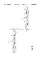
- FIG. 1is a circuit diagram of a power line communications system constructed in accordance with the present invention and having both forms of an electrical appliance constructed in accordance with the present invention.
- FIG. 2is a block diagram of the power line adapter units shown in FIG. 1.
- a power line communications systemconstructed in accordance with the present invention and having both forms of an electrical appliance constructed in accordance with the present invention, includes a power line 10, means, identified by reference numeral 12, for conducting information signals to a power line, and means, identified by reference numeral 14, for conducting information signals from a power line.
- the source of the information signalsis a first appliance 16, such as a television cable box, which has a power supply 18.
- the utilization unit of the information signalsis a second appliance 20, such as a television set, which has a power supply 22.
- first power line adapter unit 24having a power supply 26 and information signal transmitting means 27 for conducting information signals from the first appliance to power line 10.
- power line adapter unit 24includes a ferrite core coupler 29 for isolating information signal transmitting means 27 from power line 10.
- Coupler 29also couples information signals from information signal transmitting means 27 to power line 10.
- Coupler 29functions as a signal transformer and preferably is arranged to exhibit a sharp roll off below a frequency of 1 MHz, thereby attenuating interference from power line frequency 60 Hz in the United States and harmonics of the power line frequency.
- the ferrite materialis selected for the frequency range of operation, namely the nature and character of the information signals.
- ferrite core coupler 29The design parameters of ferrite core coupler 29 include the size and material of the bead or core and the number of turns. Usually, a bifilar wire is used, thereby providing close coupling between the input and the output.
- a capacitor 30 and a plug 31connect coupler 29 to power line 10 by way of an outlet 32 which is connected to the power line.
- Information signal transmitting means 27also include a band pass filter 33 for selectively passing information signals from first appliance 16 to power line 10.
- Bandpass filter 33is designed to provide minimal distortion at the frequencies of interest and attenuate out-of-band noise and interference to information signal transmitting means 27.
- Specific trapsalso can be designed to reject known interfering signals to improve system performance.
- Information signal transmitting means 27further include an impedance matching pad 34 for minimizing mismatches between the impedance of bandpass filter 33 and the impedance at outlet 32 connected to power line 10 and to which information signal transmitting means 27 are connected.
- a power linefor example from outlet 32 to another outlet, presents different loads at different times in a power line communications system.
- Impedance pad 34placed between coupler 29 and bandpass filter 33, alleviates the effect of wide variations of impedance mismatches between power line 10 and bandpass filter 33, while retaining the frequency response characteristics of bandpass filter 33.
- Information signal transmitting means 27preferably include amplifier and shaper means 35, disposed between first appliance 16 and bandpass filter 33, for amplifying and shaping the information signals supplied to information signal transmitting means 27 from first appliance 16.
- Coupler 29, bandpass filter 33, and impedance pad 34form a coupling circuit which allows the selection of a desired band of frequencies for signal transmission to the desired degree of selectivity for a given application.
- the signal bandwidthis at least 6 MHz.
- second power line adapter unit 40having a power supply 42 and information signal receiving means 43 for conducting information signals from power line 10 to the second appliance.
- power line adapter unit 40includes a ferrite core coupler 44 for isolating information signal receiving means 43 from power line 10.
- Coupler 44also couples information signals from power line 10 to information signal receiving means 43.
- coupler 44functions as a signal transformer and preferably is arranged to exhibit a sharp roll off below a frequency of 1 MHz, thereby attenuating interference from the power line frequency and its harmonics.
- the ferrite materialis selected for the frequency range of operation, namely the nature and character of the information signals.
- ferrite core coupler 44As with coupler 29, the design parameters of ferrite core coupler 44 include the size and material of the bead or core and the number of turns. Usually, a bifilar wire is used, thereby providing close coupling between the input and the output. A capacitor 45 and a plug 46 connect coupler 44 to power line 10 by way of an outlet 47 which is connected to the power line.
- Information signal receiving means 43also include a band pass filter 47 for selectively passing information signals from power line 10 to second appliance 20.
- bandpass filter 47is designed to provide minimal distortion at the frequencies of interest and attenuate out-of-band noise and interference to information signal receiving means 43.
- specific trapsalso can be designed to reject known interfering signals to improve system performance.
- Information signal receiving means 43further include an impedance matching pad 48 for minimizing mismatches between the impedance of bandpass filter 47 and the impedance at outlet 47 connected to power line 10 and to which information signal receiving means 43 are connected.
- an impedance matching pad 48for minimizing mismatches between the impedance of bandpass filter 47 and the impedance at outlet 47 connected to power line 10 and to which information signal receiving means 43 are connected.
- a power linefor example from outlet 47 to another outlet, presents different loads at different times in a power line communications system.
- Impedance pad 48placed between coupler 44 and bandpass filter 47, alleviates the effect of wide variations of impedance mismatches between power line 10 and bandpass filter 47, while retaining the frequency response characteristics of bandpass filter 47.
- Information signal receiving means 43preferably includes amplifier and shaper means 49, disposed between second appliance 20 and bandpass filter 47, for amplifying and shaping the information signals supplied to information signal receiving means 43 from power line 10.
- Coupler 44, bandpass filter 47, and impedance pad 48form a coupling circuit which allows the selection of a desired band of frequencies for signal transmission to the desired degree of selectivity for a given application.
- the signal bandwidthis at least 6 MHz.
- first appliance 16Associated with first appliance 16 is a first power line connector 56 for connecting power supply 18 of first appliance 16, power supply 26 of first power line adapter unit 24, and information signal supplying means 27, namely the circuitry of FIG. 2, to power line 10. In this way, first appliance 16 and first power line adapter unit 24 are powered and information signals from first appliance 16 are conducted through power line adapter unit 24 to power line 10.
- meansare provided for preventing the information signals from first appliance 16 from being conducted to first appliance along first power line connector 56.
- Such meansinclude, for example for the embodiment of the invention being described, a pair of inductors 60 and 62 placed in "hot” wire 56a and “neutral” wire 56b, respectively, of first power line connector 56 and which present a high impedance path for the signal frequencies of the information signals from information signal transmitting means 27 between power line 10 and "bypass" capacitor 58.
- Inductors 60 and 62can be ferrite beads in series from the "hot” and “neutral” connections, respectively, to power line 10 and "bypass" capacitor 58.
- a filter networkincluding the transformer coupler by which the information signals are coupled to power line 10, can be arranged to perform the same function. The objective of any such arrangement is to provide a low impedance path to ground for the undesirable high frequencies which might be generated within first appliance 16 and a high impedance for the frequencies of the information signals so that the information signals are conducted from information signal transmitting means 27 to power line 10.
- second appliance 20Associated with second appliance 20 is a second power line connector 64 for connecting power supply 22 of second appliance 20, power supply 42 of second power line adapter unit 40, and information signal receiving means 43, namely the circuitry of FIG. 2, to power line 10.
- second appliance 20 and second power line adapter unit 40are powered and information signals from second appliance 20 are conducted through power line adapter unit 40 to power line 10.
- meansare provided for preventing the information signals from power line 10 from being conducted to second appliance 20 along second power line connector 64.
- Such meansinclude, for the embodiment of the invention being described, a pair of inductors 66 and 68 placed in "hot" wire 64a and “neutral” wire 64b, respectively, of second power line connector 64 which present a high impedance path for the signal frequencies of the information signals from power line 10 between power line 10 and "bypass" capacitor 70.
- inductors 66 and 68can be ferrite beads in series from the "hot” and “neutral” connections, respectively, to power line 10 and "bypass" capacitor 70.
- a filter networkincluding the transformer coupler by which the information signals are coupled from power line 10, can be arranged to perform the same function. The objective of any such arrangement is to provide a low impedance path to ground for the undesirable high frequencies which might be generated within second appliance 20 and a high impedance for the frequencies of the information signals so that the information signals are conducted from power line 10 to information signal receiving means 43.
- first appliance 16is a cable television box and second appliance 20 is a television set.
- Television signals from the cable television boxare conducted through information signal transmitting means 27 and first power line connector 56 to power line 10.
- the television signalsare conducted along power line 10 and through second power line connector 64 and information signal receiving means 43 to the television set.
- power line adapter units 24 and 40each can be arranged to both transmit and receive information signals.
- power line adapter unit 40besides receiving television signals from power line 10 which are conducted to a television set (i.e. second appliance 20), can also have information signal transmitting means similar to information signal transmitting means 27, to receive remote control signals (i.e. information signals) from the television set which are conducted by power line adapter unit 40 and second power line connector 64 to power line 10.
- remote control signalsare prevented from being shorted by "bypass" capacitor 70 by inductors 66 and 68.
- these remote control signalsare conducted along power line 10 and first power line connector 56 to power line adapter unit 24, which can also have information signal receiving means, similar to information signal receiving means 43.
- the remote control signalsare conducted to a tuner control circuit for channel selection.
Landscapes
- Engineering & Computer Science (AREA)
- Power Engineering (AREA)
- Computer Networks & Wireless Communication (AREA)
- Signal Processing (AREA)
- Cable Transmission Systems, Equalization Of Radio And Reduction Of Echo (AREA)
Abstract
Description
Claims (10)
Priority Applications (3)
| Application Number | Priority Date | Filing Date | Title |
|---|---|---|---|
| US08/734,361US5805053A (en) | 1996-10-21 | 1996-10-21 | Appliance adapted for power line communications |
| PCT/US1997/019040WO1998018211A1 (en) | 1996-10-21 | 1997-10-21 | Appliance adapted for power line communications |
| AU49127/97AAU4912797A (en) | 1996-10-21 | 1997-10-21 | Appliance adapted for power line communications |
Applications Claiming Priority (1)
| Application Number | Priority Date | Filing Date | Title |
|---|---|---|---|
| US08/734,361US5805053A (en) | 1996-10-21 | 1996-10-21 | Appliance adapted for power line communications |
Publications (1)
| Publication Number | Publication Date |
|---|---|
| US5805053Atrue US5805053A (en) | 1998-09-08 |
Family
ID=24951374
Family Applications (1)
| Application Number | Title | Priority Date | Filing Date |
|---|---|---|---|
| US08/734,361Expired - LifetimeUS5805053A (en) | 1996-10-21 | 1996-10-21 | Appliance adapted for power line communications |
Country Status (3)
| Country | Link |
|---|---|
| US (1) | US5805053A (en) |
| AU (1) | AU4912797A (en) |
| WO (1) | WO1998018211A1 (en) |
Cited By (72)
| Publication number | Priority date | Publication date | Assignee | Title |
|---|---|---|---|---|
| US6297729B1 (en) | 1999-03-29 | 2001-10-02 | International Business Machines Corporation | Method and apparatus for securing communications along ac power lines |
| KR20010113231A (en)* | 2000-06-17 | 2001-12-28 | 남궁석 | Apparatus for integrated control in home appliances and power line communication apparatus therefor |
| US20020039388A1 (en)* | 2000-02-29 | 2002-04-04 | Smart Kevin J. | High data-rate powerline network system and method |
| WO2002030003A2 (en) | 2000-10-04 | 2002-04-11 | Conexant Systems, Inc. | Power line networking apparatus and method |
| US20020056116A1 (en)* | 2000-03-29 | 2002-05-09 | Wesley Smith | Home bus computer system and method |
| US6396391B1 (en)* | 1998-08-27 | 2002-05-28 | Serconet Ltd. | Communications and control network having multiple power supplies |
| US6456192B1 (en) | 2000-04-19 | 2002-09-24 | Phonex Broadband Corporation | Method and system for power line null detection and automatic frequency and gain control |
| US20030071719A1 (en)* | 2001-10-02 | 2003-04-17 | Crenshaw Ralph E. | Method and apparatus for attaching power line communications to customer premises |
| US20030095036A1 (en)* | 2001-11-19 | 2003-05-22 | Tdk Corporation | Power line communication system and power line branching apparatus |
| US6747859B2 (en)* | 2000-07-11 | 2004-06-08 | Easyplug Inc. | Modular power line network adapter |
| US6759946B2 (en) | 2001-12-06 | 2004-07-06 | Mitsubishi Electric Research Laboratories, Inc. | Home appliances network |
| US20040130413A1 (en)* | 2002-09-25 | 2004-07-08 | Intellon Corporation | Power supply system and method using analog coupling circuitry for power-line communications |
| US6771164B1 (en)* | 2002-09-05 | 2004-08-03 | Nrc Corporation | Automatic identification of local devices |
| US20040227623A1 (en)* | 2003-05-07 | 2004-11-18 | Telkonet, Inc. | Network topology and packet routing method using low voltage power wiring |
| US20040233928A1 (en)* | 2003-05-07 | 2004-11-25 | Telkonet, Inc. | Network topology and packet routing method using low voltage power wiring |
| US20050046550A1 (en)* | 2001-10-02 | 2005-03-03 | Crenshaw Ralph E. | Method and apparatus for attaching power line communications to customer premises |
| FR2864868A1 (en)* | 2004-01-06 | 2005-07-08 | Europe Adsl Leacom Fastnet Lab | Digital signal distribution installation for e.g. premises of firm, has smoothing circuit with inductors mounted on branches, where inductors are seen as short circuits and high value impedances in low and high frequencies respectively |
| US6933835B2 (en) | 2001-02-14 | 2005-08-23 | Current Technologies, Llc | Data communication over a power line |
| US20050208825A1 (en)* | 2004-03-19 | 2005-09-22 | Asoka Usa Corporation | Integrated connector for powerline network and power supply |
| US6950567B2 (en) | 2001-02-14 | 2005-09-27 | Current Technologies, Llc | Method and apparatus for providing inductive coupling and decoupling of high-frequency, high-bandwidth data signals directly on and off of a high voltage power line |
| US6958680B2 (en) | 2000-04-14 | 2005-10-25 | Current Technologies, Llc | Power line communication system and method of using the same |
| EP1432099A3 (en)* | 2002-12-19 | 2005-11-02 | Panasonic Communications Co., Ltd. | Control apparatus and control method for managing communications between multiple electrical appliances through a household power line network |
| US6965302B2 (en) | 2000-04-14 | 2005-11-15 | Current Technologies, Llc | Power line communication system and method of using the same |
| US6965303B2 (en) | 2002-12-10 | 2005-11-15 | Current Technologies, Llc | Power line communication system and method |
| EP1596467A1 (en)* | 1999-06-25 | 2005-11-16 | Cocomo Mb Communications, Inc. | Electromagnetic field in a communications system for wireless networks |
| US6977578B2 (en) | 2000-01-20 | 2005-12-20 | Current Technologies, Llc | Method of isolating data in a power line communications network |
| US6980090B2 (en) | 2002-12-10 | 2005-12-27 | Current Technologies, Llc | Device and method for coupling with electrical distribution network infrastructure to provide communications |
| US6980091B2 (en) | 2002-12-10 | 2005-12-27 | Current Technologies, Llc | Power line communication system and method of operating the same |
| US6980089B1 (en) | 2000-08-09 | 2005-12-27 | Current Technologies, Llc | Non-intrusive coupling to shielded power cable |
| US6982611B2 (en) | 2002-06-24 | 2006-01-03 | Current Technologies, Llc | Power line coupling device and method of using the same |
| US6998962B2 (en) | 2000-04-14 | 2006-02-14 | Current Technologies, Llc | Power line communication apparatus and method of using the same |
| US20060044076A1 (en)* | 2004-09-02 | 2006-03-02 | Law Robinson P S | Serial signal injection using capacitive and transformer couplings for power line communications |
| WO2005062484A3 (en)* | 2003-12-22 | 2006-03-23 | Bsh Bosch Siemens Hausgeraete | Circuit arrangement for the transmission of data signals from and/or to household appliances |
| US7046124B2 (en) | 2003-01-21 | 2006-05-16 | Current Technologies, Llc | Power line coupling device and method of using the same |
| US7053756B2 (en) | 2001-12-21 | 2006-05-30 | Current Technologies, Llc | Facilitating communication of data signals on electric power systems |
| US7064654B2 (en) | 2002-12-10 | 2006-06-20 | Current Technologies, Llc | Power line communication system and method of operating the same |
| US7075414B2 (en) | 2003-05-13 | 2006-07-11 | Current Technologies, Llc | Device and method for communicating data signals through multiple power line conductors |
| US7076378B1 (en) | 2002-11-13 | 2006-07-11 | Current Technologies, Llc | Device and method for providing power line characteristics and diagnostics |
| US20060193313A1 (en)* | 2005-02-25 | 2006-08-31 | Telkonet, Inc. | Local area network above telephony infrastructure |
| US20060193336A1 (en)* | 2005-02-25 | 2006-08-31 | Telkonet, Inc. | Local area network above cable television methods and devices |
| US20060193310A1 (en)* | 2005-02-25 | 2006-08-31 | Telkonet, Inc. | Local area network above telephony methods and devices |
| US7102478B2 (en) | 2002-06-21 | 2006-09-05 | Current Technologies, Llc | Power line coupling device and method of using the same |
| US7113134B1 (en) | 2004-03-12 | 2006-09-26 | Current Technologies, Llc | Transformer antenna device and method of using the same |
| US20060227884A1 (en)* | 2005-04-08 | 2006-10-12 | Matsushita Electric Industrial Co., Ltd. | Relay apparatus and electric appliance |
| US7132819B1 (en) | 2002-11-12 | 2006-11-07 | Current Technologies, Llc | Floating power supply and method of using the same |
| US20060262881A1 (en)* | 2005-05-20 | 2006-11-23 | Yehuda Cern | Power line communications interface and surge protector |
| US20060271970A1 (en)* | 2005-05-17 | 2006-11-30 | Mitchell Bradley J | Apparatus and method for transmitting information between seats in a mobile platform using an existing power line |
| US20070047573A1 (en)* | 2005-08-29 | 2007-03-01 | Arkados, Inc. | Networking and multimedia adapter for power outlets |
| US7199699B1 (en) | 2002-02-19 | 2007-04-03 | Current Technologies, Llc | Facilitating communication with power line communication devices |
| US7308103B2 (en) | 2003-05-08 | 2007-12-11 | Current Technologies, Llc | Power line communication device and method of using the same |
| US7317793B2 (en) | 2003-01-30 | 2008-01-08 | Serconet Ltd | Method and system for providing DC power on local telephone lines |
| US7327221B1 (en) | 2003-09-30 | 2008-02-05 | Rockwell Automation Technologies, Inc. | Power supply communication system and method |
| US7424031B2 (en) | 1998-07-28 | 2008-09-09 | Serconet, Ltd. | Local area network of serial intelligent cells |
| USRE40492E1 (en) | 2000-02-10 | 2008-09-09 | Telkonet Communications, Inc. | Power line telephony exchange |
| US7460467B1 (en) | 2003-07-23 | 2008-12-02 | Current Technologies, Llc | Voice-over-IP network test device and method |
| US7483524B2 (en) | 1999-07-20 | 2009-01-27 | Serconet, Ltd | Network for telephony and data communication |
| US7522714B2 (en) | 2000-03-20 | 2009-04-21 | Serconet Ltd. | Telephone outlet for implementing a local area network over telephone lines and a local area network using such outlets |
| US20090107566A1 (en)* | 2007-10-24 | 2009-04-30 | Festo Ag & Co. Kg | Fluid power valve arrangement with at least one solenoid valve |
| US20090212926A1 (en)* | 2008-02-23 | 2009-08-27 | Ruoping Du | Baby Monitor |
| US7656904B2 (en) | 2003-03-13 | 2010-02-02 | Mosaid Technologies Incorporated | Telephone system having multiple distinct sources and accessories therefor |
| US7810125B2 (en) | 2001-07-01 | 2010-10-05 | Phonex Broadband Corporation | Method and system for a low cost wireless telephone link for a set top box |
| US7876767B2 (en) | 2000-04-19 | 2011-01-25 | Mosaid Technologies Incorporated | Network combining wired and non-wired segments |
| US20110101956A1 (en)* | 2009-11-04 | 2011-05-05 | David Wayne Thorn | Electricity Usage Monitor System |
| CN102111187A (en)* | 2010-12-27 | 2011-06-29 | 东莞市华业新科电子科技有限公司 | Power line carrier communication module |
| US20120076186A1 (en)* | 2008-01-08 | 2012-03-29 | Sony Corporation | Communication system and communication apparatus |
| US20120201312A1 (en)* | 2011-02-07 | 2012-08-09 | Sony Corporation | Power line communication apparatus including ac power socket |
| US8582598B2 (en) | 1999-07-07 | 2013-11-12 | Mosaid Technologies Incorporated | Local area network for distributing data communication, sensing and control signals |
| US8704654B1 (en)* | 2007-06-07 | 2014-04-22 | The United States Of America As Represented By The Administrator Of National Aeronautics And Space Administration | Circuit for communication over DC power line using high temperature electronics |
| WO2014167799A1 (en)* | 2013-04-12 | 2014-10-16 | パナソニック株式会社 | Communication terminal and communication system |
| US9577707B1 (en)* | 2014-07-14 | 2017-02-21 | Marvell International Ltd. | Method and device for stabilizing impedance on a power-line communication device |
| US20180062429A1 (en)* | 2016-08-29 | 2018-03-01 | Sungrow Power Supply Co., Ltd. | Power carrier signal coupling circuit and communication system |
| US10986164B2 (en) | 2004-01-13 | 2021-04-20 | May Patents Ltd. | Information device |
Families Citing this family (5)
| Publication number | Priority date | Publication date | Assignee | Title |
|---|---|---|---|---|
| US8419650B2 (en) | 1999-04-16 | 2013-04-16 | Cariocom, LLC | Downloadable datasets for a patient monitoring system |
| DE10050476B4 (en)* | 2000-10-12 | 2005-03-31 | IAD Gesellschaft für Informatik, Automatisierung und Datenverarbeitung mbH | Apparatus for performing both measurements and data transmission in electrical power distribution networks |
| FR2844600A1 (en)* | 2002-09-13 | 2004-03-19 | Thomson Licensing Sa | Second subscription domestic e.g. television, apparatus checking relative position domestic network method having alternating electrical periods measured first/second apparatus and offset comparison verified/not verified |
| US20070231846A1 (en)* | 2006-04-03 | 2007-10-04 | Cosentino Daniel L | Glucose meter communication method and system |
| US9395234B2 (en) | 2012-12-05 | 2016-07-19 | Cardiocom, Llc | Stabilizing base for scale |
Citations (21)
| Publication number | Priority date | Publication date | Assignee | Title |
|---|---|---|---|---|
| US3400221A (en)* | 1963-06-14 | 1968-09-03 | Gen Electric | Music distribution system using fm transmission over house wiring |
| US3846638A (en)* | 1972-10-02 | 1974-11-05 | Gen Electric | Improved coupling arrangement for power line carrier systems |
| US3949172A (en)* | 1974-02-08 | 1976-04-06 | Brown William M | Telephone extension system utilizing power line carrier signals |
| US4058678A (en)* | 1976-04-07 | 1977-11-15 | Astech, Inc. | Remote signalling to a telephone line utilizing power line carrier signals |
| US4377804A (en)* | 1979-10-31 | 1983-03-22 | Matsushita Electric Works, Ltd. | Synchronous data transmission system utilizing AC power line |
| US4475193A (en)* | 1982-09-30 | 1984-10-02 | Astech, Inc. | Power line carrier multi telephone extension system for full duplex conferencing between telephones |
| US4479033A (en)* | 1982-03-29 | 1984-10-23 | Astech, Inc. | Telephone extension system utilizing power line carrier signals |
| US4495386A (en)* | 1982-03-29 | 1985-01-22 | Astech, Inc. | Telephone extension system utilizing power line carrier signals |
| US4509211A (en)* | 1983-05-16 | 1985-04-02 | Xantech Corporation | Infrared extension system |
| US4514594A (en)* | 1982-09-30 | 1985-04-30 | Astech, Inc. | Power line carrier telephone extension system for full duplex conferencing between telephones and having telephone call hold capability |
| US4523307A (en)* | 1982-11-30 | 1985-06-11 | Astech, Inc. | Power line carrier multi telephone extension system for full duplex conferencing and intercom between telephones |
| US4701945A (en)* | 1984-10-09 | 1987-10-20 | Pedigo Michael K | Carrier current transceiver |
| US4885563A (en)* | 1988-05-03 | 1989-12-05 | Thermo King Corporation | Power line carrier communication system |
| US4980665A (en)* | 1987-05-22 | 1990-12-25 | Recoton Corporation | Remote control repeater |
| US5210519A (en)* | 1990-06-22 | 1993-05-11 | British Aerospace Public Limited Company | Digital data transmission |
| WO1994009572A1 (en)* | 1992-10-22 | 1994-04-28 | Norweb Plc | Transmission network and filter therefor |
| US5455467A (en)* | 1991-12-18 | 1995-10-03 | Apple Computer, Inc. | Power connection scheme |
| WO1996008892A1 (en)* | 1994-09-12 | 1996-03-21 | Videocom, Inc. | Video distribution system using in-wall wiring |
| US5530737A (en)* | 1993-03-22 | 1996-06-25 | Phonex Corporation | Secure access telephone extension system and method |
| US5533101A (en)* | 1993-07-28 | 1996-07-02 | Rohm Co. Ltd. | Extension phone type cordless telephone set |
| US5574653A (en)* | 1990-06-25 | 1996-11-12 | The South East Queensland Electricity Board | Switchboard |
- 1996
- 1996-10-21USUS08/734,361patent/US5805053A/ennot_activeExpired - Lifetime
- 1997
- 1997-10-21AUAU49127/97Apatent/AU4912797A/ennot_activeAbandoned
- 1997-10-21WOPCT/US1997/019040patent/WO1998018211A1/enactiveApplication Filing
Patent Citations (21)
| Publication number | Priority date | Publication date | Assignee | Title |
|---|---|---|---|---|
| US3400221A (en)* | 1963-06-14 | 1968-09-03 | Gen Electric | Music distribution system using fm transmission over house wiring |
| US3846638A (en)* | 1972-10-02 | 1974-11-05 | Gen Electric | Improved coupling arrangement for power line carrier systems |
| US3949172A (en)* | 1974-02-08 | 1976-04-06 | Brown William M | Telephone extension system utilizing power line carrier signals |
| US4058678A (en)* | 1976-04-07 | 1977-11-15 | Astech, Inc. | Remote signalling to a telephone line utilizing power line carrier signals |
| US4377804A (en)* | 1979-10-31 | 1983-03-22 | Matsushita Electric Works, Ltd. | Synchronous data transmission system utilizing AC power line |
| US4479033A (en)* | 1982-03-29 | 1984-10-23 | Astech, Inc. | Telephone extension system utilizing power line carrier signals |
| US4495386A (en)* | 1982-03-29 | 1985-01-22 | Astech, Inc. | Telephone extension system utilizing power line carrier signals |
| US4514594A (en)* | 1982-09-30 | 1985-04-30 | Astech, Inc. | Power line carrier telephone extension system for full duplex conferencing between telephones and having telephone call hold capability |
| US4475193A (en)* | 1982-09-30 | 1984-10-02 | Astech, Inc. | Power line carrier multi telephone extension system for full duplex conferencing between telephones |
| US4523307A (en)* | 1982-11-30 | 1985-06-11 | Astech, Inc. | Power line carrier multi telephone extension system for full duplex conferencing and intercom between telephones |
| US4509211A (en)* | 1983-05-16 | 1985-04-02 | Xantech Corporation | Infrared extension system |
| US4701945A (en)* | 1984-10-09 | 1987-10-20 | Pedigo Michael K | Carrier current transceiver |
| US4980665A (en)* | 1987-05-22 | 1990-12-25 | Recoton Corporation | Remote control repeater |
| US4885563A (en)* | 1988-05-03 | 1989-12-05 | Thermo King Corporation | Power line carrier communication system |
| US5210519A (en)* | 1990-06-22 | 1993-05-11 | British Aerospace Public Limited Company | Digital data transmission |
| US5574653A (en)* | 1990-06-25 | 1996-11-12 | The South East Queensland Electricity Board | Switchboard |
| US5455467A (en)* | 1991-12-18 | 1995-10-03 | Apple Computer, Inc. | Power connection scheme |
| WO1994009572A1 (en)* | 1992-10-22 | 1994-04-28 | Norweb Plc | Transmission network and filter therefor |
| US5530737A (en)* | 1993-03-22 | 1996-06-25 | Phonex Corporation | Secure access telephone extension system and method |
| US5533101A (en)* | 1993-07-28 | 1996-07-02 | Rohm Co. Ltd. | Extension phone type cordless telephone set |
| WO1996008892A1 (en)* | 1994-09-12 | 1996-03-21 | Videocom, Inc. | Video distribution system using in-wall wiring |
Cited By (139)
| Publication number | Priority date | Publication date | Assignee | Title |
|---|---|---|---|---|
| US8325636B2 (en) | 1998-07-28 | 2012-12-04 | Mosaid Technologies Incorporated | Local area network of serial intelligent cells |
| US8885659B2 (en) | 1998-07-28 | 2014-11-11 | Conversant Intellectual Property Management Incorporated | Local area network of serial intelligent cells |
| US8270430B2 (en) | 1998-07-28 | 2012-09-18 | Mosaid Technologies Incorporated | Local area network of serial intelligent cells |
| US8867523B2 (en) | 1998-07-28 | 2014-10-21 | Conversant Intellectual Property Management Incorporated | Local area network of serial intelligent cells |
| US7965735B2 (en) | 1998-07-28 | 2011-06-21 | Mosaid Technologies Incorporated | Local area network of serial intelligent cells |
| US7830858B2 (en) | 1998-07-28 | 2010-11-09 | Mosaid Technologies Incorporated | Local area network of serial intelligent cells |
| US7424031B2 (en) | 1998-07-28 | 2008-09-09 | Serconet, Ltd. | Local area network of serial intelligent cells |
| US7969917B2 (en) | 1998-07-28 | 2011-06-28 | Mosaid Technologies Incorporated | Local area network of serial intelligent cells |
| US7852874B2 (en) | 1998-07-28 | 2010-12-14 | Mosaid Technologies Incorporated | Local area network of serial intelligent cells |
| US8885660B2 (en) | 1998-07-28 | 2014-11-11 | Conversant Intellectual Property Management Incorporated | Local area network of serial intelligent cells |
| US7986708B2 (en) | 1998-07-28 | 2011-07-26 | Mosaid Technologies Incorporated | Local area network of serial intelligent cells |
| US7653015B2 (en) | 1998-07-28 | 2010-01-26 | Mosaid Technologies Incorporated | Local area network of serial intelligent cells |
| US7978726B2 (en) | 1998-07-28 | 2011-07-12 | Mosaid Technologies Incorporated | Local area network of serial intelligent cells |
| US8908673B2 (en) | 1998-07-28 | 2014-12-09 | Conversant Intellectual Property Management Incorporated | Local area network of serial intelligent cells |
| US6396391B1 (en)* | 1998-08-27 | 2002-05-28 | Serconet Ltd. | Communications and control network having multiple power supplies |
| US6297729B1 (en) | 1999-03-29 | 2001-10-02 | International Business Machines Corporation | Method and apparatus for securing communications along ac power lines |
| EP1596467A1 (en)* | 1999-06-25 | 2005-11-16 | Cocomo Mb Communications, Inc. | Electromagnetic field in a communications system for wireless networks |
| US8582598B2 (en) | 1999-07-07 | 2013-11-12 | Mosaid Technologies Incorporated | Local area network for distributing data communication, sensing and control signals |
| US7483524B2 (en) | 1999-07-20 | 2009-01-27 | Serconet, Ltd | Network for telephony and data communication |
| US8929523B2 (en) | 1999-07-20 | 2015-01-06 | Conversant Intellectual Property Management Inc. | Network for telephony and data communication |
| US8351582B2 (en) | 1999-07-20 | 2013-01-08 | Mosaid Technologies Incorporated | Network for telephony and data communication |
| US7522713B2 (en) | 1999-07-20 | 2009-04-21 | Serconet, Ltd. | Network for telephony and data communication |
| US7492875B2 (en) | 1999-07-20 | 2009-02-17 | Serconet, Ltd. | Network for telephony and data communication |
| US6977578B2 (en) | 2000-01-20 | 2005-12-20 | Current Technologies, Llc | Method of isolating data in a power line communications network |
| USRE40492E1 (en) | 2000-02-10 | 2008-09-09 | Telkonet Communications, Inc. | Power line telephony exchange |
| US20020039388A1 (en)* | 2000-02-29 | 2002-04-04 | Smart Kevin J. | High data-rate powerline network system and method |
| US7522714B2 (en) | 2000-03-20 | 2009-04-21 | Serconet Ltd. | Telephone outlet for implementing a local area network over telephone lines and a local area network using such outlets |
| US7715534B2 (en) | 2000-03-20 | 2010-05-11 | Mosaid Technologies Incorporated | Telephone outlet for implementing a local area network over telephone lines and a local area network using such outlets |
| US8363797B2 (en) | 2000-03-20 | 2013-01-29 | Mosaid Technologies Incorporated | Telephone outlet for implementing a local area network over telephone lines and a local area network using such outlets |
| US8855277B2 (en) | 2000-03-20 | 2014-10-07 | Conversant Intellectual Property Managment Incorporated | Telephone outlet for implementing a local area network over telephone lines and a local area network using such outlets |
| US20020056116A1 (en)* | 2000-03-29 | 2002-05-09 | Wesley Smith | Home bus computer system and method |
| US6965302B2 (en) | 2000-04-14 | 2005-11-15 | Current Technologies, Llc | Power line communication system and method of using the same |
| US6958680B2 (en) | 2000-04-14 | 2005-10-25 | Current Technologies, Llc | Power line communication system and method of using the same |
| US7245212B2 (en) | 2000-04-14 | 2007-07-17 | Current Technologies, Llc | Power line communication apparatus and method of using the same |
| US6998962B2 (en) | 2000-04-14 | 2006-02-14 | Current Technologies, Llc | Power line communication apparatus and method of using the same |
| US7307511B2 (en) | 2000-04-14 | 2007-12-11 | Current Technologies, Llc | Power line communication system and method |
| US7876767B2 (en) | 2000-04-19 | 2011-01-25 | Mosaid Technologies Incorporated | Network combining wired and non-wired segments |
| US8848725B2 (en) | 2000-04-19 | 2014-09-30 | Conversant Intellectual Property Management Incorporated | Network combining wired and non-wired segments |
| US7933297B2 (en) | 2000-04-19 | 2011-04-26 | Mosaid Technologies Incorporated | Network combining wired and non-wired segments |
| US8867506B2 (en) | 2000-04-19 | 2014-10-21 | Conversant Intellectual Property Management Incorporated | Network combining wired and non-wired segments |
| US8873586B2 (en) | 2000-04-19 | 2014-10-28 | Conversant Intellectual Property Management Incorporated | Network combining wired and non-wired segments |
| US6456192B1 (en) | 2000-04-19 | 2002-09-24 | Phonex Broadband Corporation | Method and system for power line null detection and automatic frequency and gain control |
| US8982904B2 (en) | 2000-04-19 | 2015-03-17 | Conversant Intellectual Property Management Inc. | Network combining wired and non-wired segments |
| KR20010113231A (en)* | 2000-06-17 | 2001-12-28 | 남궁석 | Apparatus for integrated control in home appliances and power line communication apparatus therefor |
| US6747859B2 (en)* | 2000-07-11 | 2004-06-08 | Easyplug Inc. | Modular power line network adapter |
| US7230811B2 (en) | 2000-07-11 | 2007-06-12 | Walbeck Alan K | Modular power line network adapter |
| US20050063535A1 (en)* | 2000-07-11 | 2005-03-24 | Walbeck Alan K. | Modular power line network adapter |
| US6980089B1 (en) | 2000-08-09 | 2005-12-27 | Current Technologies, Llc | Non-intrusive coupling to shielded power cable |
| US6741162B1 (en) | 2000-10-04 | 2004-05-25 | Conexant Systems, Inc. | Power line networking apparatus and method |
| WO2002030003A3 (en)* | 2000-10-04 | 2002-08-15 | Conexant Systems Inc | Power line networking apparatus and method |
| WO2002030003A2 (en) | 2000-10-04 | 2002-04-11 | Conexant Systems, Inc. | Power line networking apparatus and method |
| US6950567B2 (en) | 2001-02-14 | 2005-09-27 | Current Technologies, Llc | Method and apparatus for providing inductive coupling and decoupling of high-frequency, high-bandwidth data signals directly on and off of a high voltage power line |
| US7103240B2 (en) | 2001-02-14 | 2006-09-05 | Current Technologies, Llc | Method and apparatus for providing inductive coupling and decoupling of high-frequency, high-bandwidth data signals directly on and off of a high voltage power line |
| US6933835B2 (en) | 2001-02-14 | 2005-08-23 | Current Technologies, Llc | Data communication over a power line |
| US7453352B2 (en) | 2001-02-14 | 2008-11-18 | Current Technologies, Llc | Data communication over a power line |
| US7218219B2 (en) | 2001-02-14 | 2007-05-15 | Current Technologies, Llc | Data communication over a power line |
| US7042351B2 (en) | 2001-02-14 | 2006-05-09 | Current Technologies, Llc | Data communication over a power line |
| US7414518B2 (en) | 2001-02-14 | 2008-08-19 | Current Technologies, Llc | Power line communication device and method |
| US7810125B2 (en) | 2001-07-01 | 2010-10-05 | Phonex Broadband Corporation | Method and system for a low cost wireless telephone link for a set top box |
| US7091831B2 (en) | 2001-10-02 | 2006-08-15 | Telkonet Communications, Inc. | Method and apparatus for attaching power line communications to customer premises |
| US20050248441A1 (en)* | 2001-10-02 | 2005-11-10 | Telkonet Communications, Inc. | Method and apparatus for attaching power line communications to customer premises |
| US6975212B2 (en) | 2001-10-02 | 2005-12-13 | Telkonet Communications, Inc. | Method and apparatus for attaching power line communications to customer premises |
| US20030071719A1 (en)* | 2001-10-02 | 2003-04-17 | Crenshaw Ralph E. | Method and apparatus for attaching power line communications to customer premises |
| US20050046550A1 (en)* | 2001-10-02 | 2005-03-03 | Crenshaw Ralph E. | Method and apparatus for attaching power line communications to customer premises |
| US20050253690A1 (en)* | 2001-10-02 | 2005-11-17 | Telkonet Communications, Inc. | Method and apparatus for attaching power line communications to customer premises |
| US6987430B2 (en)* | 2001-11-19 | 2006-01-17 | Tdk Corporation | Power line communication system and power line branching apparatus |
| US20030095036A1 (en)* | 2001-11-19 | 2003-05-22 | Tdk Corporation | Power line communication system and power line branching apparatus |
| US6759946B2 (en) | 2001-12-06 | 2004-07-06 | Mitsubishi Electric Research Laboratories, Inc. | Home appliances network |
| US7053756B2 (en) | 2001-12-21 | 2006-05-30 | Current Technologies, Llc | Facilitating communication of data signals on electric power systems |
| US7199699B1 (en) | 2002-02-19 | 2007-04-03 | Current Technologies, Llc | Facilitating communication with power line communication devices |
| US7102478B2 (en) | 2002-06-21 | 2006-09-05 | Current Technologies, Llc | Power line coupling device and method of using the same |
| US7224243B2 (en) | 2002-06-24 | 2007-05-29 | Current Technologies, Llc | Power line coupling device and method of using the same |
| US6982611B2 (en) | 2002-06-24 | 2006-01-03 | Current Technologies, Llc | Power line coupling device and method of using the same |
| US6771164B1 (en)* | 2002-09-05 | 2004-08-03 | Nrc Corporation | Automatic identification of local devices |
| US20040130413A1 (en)* | 2002-09-25 | 2004-07-08 | Intellon Corporation | Power supply system and method using analog coupling circuitry for power-line communications |
| US7132819B1 (en) | 2002-11-12 | 2006-11-07 | Current Technologies, Llc | Floating power supply and method of using the same |
| US7076378B1 (en) | 2002-11-13 | 2006-07-11 | Current Technologies, Llc | Device and method for providing power line characteristics and diagnostics |
| US6980090B2 (en) | 2002-12-10 | 2005-12-27 | Current Technologies, Llc | Device and method for coupling with electrical distribution network infrastructure to provide communications |
| US7250848B2 (en) | 2002-12-10 | 2007-07-31 | Current Technologies, Llc | Power line communication apparatus and method of using the same |
| US7064654B2 (en) | 2002-12-10 | 2006-06-20 | Current Technologies, Llc | Power line communication system and method of operating the same |
| US7701325B2 (en) | 2002-12-10 | 2010-04-20 | Current Technologies, Llc | Power line communication apparatus and method of using the same |
| US6980091B2 (en) | 2002-12-10 | 2005-12-27 | Current Technologies, Llc | Power line communication system and method of operating the same |
| US6965303B2 (en) | 2002-12-10 | 2005-11-15 | Current Technologies, Llc | Power line communication system and method |
| US7301440B2 (en) | 2002-12-10 | 2007-11-27 | Current Technologies, Llc | Power line communication system and method |
| EP1432099A3 (en)* | 2002-12-19 | 2005-11-02 | Panasonic Communications Co., Ltd. | Control apparatus and control method for managing communications between multiple electrical appliances through a household power line network |
| US7046124B2 (en) | 2003-01-21 | 2006-05-16 | Current Technologies, Llc | Power line coupling device and method of using the same |
| US7317793B2 (en) | 2003-01-30 | 2008-01-08 | Serconet Ltd | Method and system for providing DC power on local telephone lines |
| US7702095B2 (en) | 2003-01-30 | 2010-04-20 | Mosaid Technologies Incorporated | Method and system for providing DC power on local telephone lines |
| US8787562B2 (en) | 2003-01-30 | 2014-07-22 | Conversant Intellectual Property Management Inc. | Method and system for providing DC power on local telephone lines |
| US8107618B2 (en) | 2003-01-30 | 2012-01-31 | Mosaid Technologies Incorporated | Method and system for providing DC power on local telephone lines |
| US7656904B2 (en) | 2003-03-13 | 2010-02-02 | Mosaid Technologies Incorporated | Telephone system having multiple distinct sources and accessories therefor |
| US20040233928A1 (en)* | 2003-05-07 | 2004-11-25 | Telkonet, Inc. | Network topology and packet routing method using low voltage power wiring |
| US20040227623A1 (en)* | 2003-05-07 | 2004-11-18 | Telkonet, Inc. | Network topology and packet routing method using low voltage power wiring |
| US7308103B2 (en) | 2003-05-08 | 2007-12-11 | Current Technologies, Llc | Power line communication device and method of using the same |
| US7075414B2 (en) | 2003-05-13 | 2006-07-11 | Current Technologies, Llc | Device and method for communicating data signals through multiple power line conductors |
| US7460467B1 (en) | 2003-07-23 | 2008-12-02 | Current Technologies, Llc | Voice-over-IP network test device and method |
| US7327221B1 (en) | 2003-09-30 | 2008-02-05 | Rockwell Automation Technologies, Inc. | Power supply communication system and method |
| US7907050B1 (en) | 2003-09-30 | 2011-03-15 | Rockwell Automation Technologies, Inc. | Power supply communication system and method |
| EP1816755A3 (en)* | 2003-12-22 | 2007-08-15 | BSH Bosch und Siemens Hausgeräte GmbH | Circuit arrangement for the transmission of data signals from and/or to houshold appliances |
| US20070139186A1 (en)* | 2003-12-22 | 2007-06-21 | Bsh Bosch Und Siemens Hausgerate Gmbh | Circuit configuration for transmission of data signals from and/or to household appliances |
| WO2005062484A3 (en)* | 2003-12-22 | 2006-03-23 | Bsh Bosch Siemens Hausgeraete | Circuit arrangement for the transmission of data signals from and/or to household appliances |
| FR2864868A1 (en)* | 2004-01-06 | 2005-07-08 | Europe Adsl Leacom Fastnet Lab | Digital signal distribution installation for e.g. premises of firm, has smoothing circuit with inductors mounted on branches, where inductors are seen as short circuits and high value impedances in low and high frequencies respectively |
| WO2005071860A3 (en)* | 2004-01-06 | 2005-09-22 | Europe Adsl Lab | Method and system for interfacing an item of equipment having electrical power distribution line carrier currents, and a device |
| US11095708B2 (en) | 2004-01-13 | 2021-08-17 | May Patents Ltd. | Information device |
| US11032353B2 (en) | 2004-01-13 | 2021-06-08 | May Patents Ltd. | Information device |
| US10986164B2 (en) | 2004-01-13 | 2021-04-20 | May Patents Ltd. | Information device |
| US7113134B1 (en) | 2004-03-12 | 2006-09-26 | Current Technologies, Llc | Transformer antenna device and method of using the same |
| US7387529B2 (en)* | 2004-03-19 | 2008-06-17 | Asoka Usa Corporation | Integrated connector for powerline network and power supply |
| US20060199427A1 (en)* | 2004-03-19 | 2006-09-07 | Asoka Usa Corporation | Integrated connector for powerline network and power supply |
| US20050208825A1 (en)* | 2004-03-19 | 2005-09-22 | Asoka Usa Corporation | Integrated connector for powerline network and power supply |
| US7413471B2 (en)* | 2004-03-19 | 2008-08-19 | Asoka Usa Corporation | Integrated connector for powerline network and power supply |
| US7286026B2 (en)* | 2004-09-02 | 2007-10-23 | Avago Technologies Ecbu Ip (Singapore) Pte. Ltd. | Serial signal injection using capacitive and transformer couplings for power line communications |
| US20060044076A1 (en)* | 2004-09-02 | 2006-03-02 | Law Robinson P S | Serial signal injection using capacitive and transformer couplings for power line communications |
| US20060193336A1 (en)* | 2005-02-25 | 2006-08-31 | Telkonet, Inc. | Local area network above cable television methods and devices |
| US20060193313A1 (en)* | 2005-02-25 | 2006-08-31 | Telkonet, Inc. | Local area network above telephony infrastructure |
| US20060193310A1 (en)* | 2005-02-25 | 2006-08-31 | Telkonet, Inc. | Local area network above telephony methods and devices |
| US8040235B2 (en)* | 2005-04-08 | 2011-10-18 | Panasonic Corporation | Relay apparatus and electric appliance |
| US20060227884A1 (en)* | 2005-04-08 | 2006-10-12 | Matsushita Electric Industrial Co., Ltd. | Relay apparatus and electric appliance |
| US20060271970A1 (en)* | 2005-05-17 | 2006-11-30 | Mitchell Bradley J | Apparatus and method for transmitting information between seats in a mobile platform using an existing power line |
| US20060262881A1 (en)* | 2005-05-20 | 2006-11-23 | Yehuda Cern | Power line communications interface and surge protector |
| US7339458B2 (en) | 2005-05-20 | 2008-03-04 | Ambient Corporation | Power line communications interface and surge protector |
| US7830248B2 (en) | 2005-08-29 | 2010-11-09 | Arkados, Inc. | Networking and multimedia adapter for power outlets |
| US20070047573A1 (en)* | 2005-08-29 | 2007-03-01 | Arkados, Inc. | Networking and multimedia adapter for power outlets |
| US8704654B1 (en)* | 2007-06-07 | 2014-04-22 | The United States Of America As Represented By The Administrator Of National Aeronautics And Space Administration | Circuit for communication over DC power line using high temperature electronics |
| US20090107566A1 (en)* | 2007-10-24 | 2009-04-30 | Festo Ag & Co. Kg | Fluid power valve arrangement with at least one solenoid valve |
| US8151823B2 (en)* | 2007-10-24 | 2012-04-10 | Festo Ag & Co. Kg | Fluid power valve arrangement with at least one solenoid valve |
| US20120076186A1 (en)* | 2008-01-08 | 2012-03-29 | Sony Corporation | Communication system and communication apparatus |
| US8390143B2 (en)* | 2008-01-08 | 2013-03-05 | Sony Corporation | Communication system and communication apparatus |
| US20090212926A1 (en)* | 2008-02-23 | 2009-08-27 | Ruoping Du | Baby Monitor |
| US20110101956A1 (en)* | 2009-11-04 | 2011-05-05 | David Wayne Thorn | Electricity Usage Monitor System |
| CN102111187A (en)* | 2010-12-27 | 2011-06-29 | 东莞市华业新科电子科技有限公司 | Power line carrier communication module |
| US10097242B2 (en) | 2011-02-07 | 2018-10-09 | Sony Corporation | Power line communication apparatus including AC power socket |
| US20120201312A1 (en)* | 2011-02-07 | 2012-08-09 | Sony Corporation | Power line communication apparatus including ac power socket |
| US9172433B2 (en)* | 2011-02-07 | 2015-10-27 | Sony Corporation | Power line communication apparatus including AC power socket |
| JPWO2014167799A1 (en)* | 2013-04-12 | 2017-02-16 | パナソニックIpマネジメント株式会社 | Communication terminal and communication system |
| WO2014167799A1 (en)* | 2013-04-12 | 2014-10-16 | パナソニック株式会社 | Communication terminal and communication system |
| US9577707B1 (en)* | 2014-07-14 | 2017-02-21 | Marvell International Ltd. | Method and device for stabilizing impedance on a power-line communication device |
| US10056781B2 (en)* | 2016-08-29 | 2018-08-21 | Sungrow Power Supply Co., Ltd. | Power carrier signal coupling circuit and communication system |
| US20180062429A1 (en)* | 2016-08-29 | 2018-03-01 | Sungrow Power Supply Co., Ltd. | Power carrier signal coupling circuit and communication system |
Also Published As
| Publication number | Publication date |
|---|---|
| AU4912797A (en) | 1998-05-15 |
| WO1998018211A1 (en) | 1998-04-30 |
Similar Documents
| Publication | Publication Date | Title |
|---|---|---|
| US5805053A (en) | Appliance adapted for power line communications | |
| US5705974A (en) | Power line communications system and coupling circuit for power line communications system | |
| US5712614A (en) | Power line communications system | |
| US4973940A (en) | Optimum impedance system for coupling transceiver to power line carrier network | |
| US7456516B2 (en) | Power line terminating circuit and method, and power line relay device | |
| US6172597B1 (en) | Electricity distribution and/or power transmission network and filter for telecommunication over power lines | |
| US5151838A (en) | Video multiplying system | |
| US20100251323A1 (en) | Upstream bandwidth conditioning device | |
| US8830009B2 (en) | Power supply cable for power line communication equipment | |
| WO2002089352A1 (en) | Device for electrically connecting a modem to an electric network for line-bound transmission of data | |
| EP0965181B1 (en) | Power line communications system | |
| US5045823A (en) | Terminating scheme for transmitting multiple signals on a coaxial cable to multiple tap outlets | |
| US5574749A (en) | Line interface apparatus and method for isolating data terminal equipment from the line | |
| JP2003283390A (en) | Power line carrier communication inductor loading device | |
| US8810059B2 (en) | Effective low voltage to medium voltage transmission on PRIME band | |
| US7039360B2 (en) | External noise intrusion prevention device, signal amplifier, protector and antenna plug | |
| AU603047B2 (en) | Improvements in or relating to cordless telephones | |
| US6757386B1 (en) | Apparatus, system, and method for efficient reduction of electromagnetic interference in telecommunications equipment | |
| EP0965178B1 (en) | System and coupling circuit for power line communications | |
| JPH0461428A (en) | High frequency signal changeover circuit | |
| KR200198496Y1 (en) | A two distributor for a enclosure filter | |
| JP2000195622A (en) | CATV protector | |
| CN2402081Y (en) | A Device for Improving the Attenuation of High-frequency Signals in Cable TV Distributors | |
| CN112910494A (en) | Signal monitoring circuit and method and electronic equipment | |
| JPH099240A (en) | Protector for branching type communication |
Legal Events
| Date | Code | Title | Description |
|---|---|---|---|
| AS | Assignment | Owner name:ELCOM TECHNOLOGIES CORPORATION, PENNSYLVANIA Free format text:ASSIGNMENT OF ASSIGNORS INTEREST;ASSIGNORS:PATEL, CHANDRAKANT BHAILALBHAI;HARFORD, JACK RUDOLPH;SEGGERN, GLEN;REEL/FRAME:008280/0596;SIGNING DATES FROM 19961008 TO 19961014 | |
| STCF | Information on status: patent grant | Free format text:PATENTED CASE | |
| AS | Assignment | Owner name:PHONEX CORPORATION, UTAH Free format text:ASSIGNMENT OF ASSIGNORS INTEREST;ASSIGNOR:ELCOM TECHNOLOGIES CORPORATION;REEL/FRAME:009922/0768 Effective date:19990302 | |
| FPAY | Fee payment | Year of fee payment:4 | |
| AS | Assignment | Owner name:SILICON VALLEY BANK, CALIFORNIA Free format text:SECURITY AGREEMENT;ASSIGNOR:PHONEX BROADBAND CORP.;REEL/FRAME:014066/0489 Effective date:20030414 | |
| AS | Assignment | Owner name:PHONEX BROADBAND CORPORATION, UTAH Free format text:RELEASE;ASSIGNOR:SILICON VALLEY BANK;REEL/FRAME:016662/0702 Effective date:20050606 | |
| FPAY | Fee payment | Year of fee payment:8 | |
| FEPP | Fee payment procedure | Free format text:PAYER NUMBER DE-ASSIGNED (ORIGINAL EVENT CODE: RMPN); ENTITY STATUS OF PATENT OWNER: LARGE ENTITY Free format text:PAYOR NUMBER ASSIGNED (ORIGINAL EVENT CODE: ASPN); ENTITY STATUS OF PATENT OWNER: LARGE ENTITY | |
| FPAY | Fee payment | Year of fee payment:12 | |
| AS | Assignment | Owner name:D.P. KELLY & ASSOCIATES, L.P.,ILLINOIS Free format text:SECURITY AGREEMENT;ASSIGNOR:PHONEX BROADBAND CORPORATION;REEL/FRAME:024023/0084 Effective date:20091222 Owner name:D.P. KELLY & ASSOCIATES, L.P., ILLINOIS Free format text:SECURITY AGREEMENT;ASSIGNOR:PHONEX BROADBAND CORPORATION;REEL/FRAME:024023/0084 Effective date:20091222 | |
| AS | Assignment | Owner name:PHONEX BROADBAND CORPORATION, UTAH Free format text:RELEASE BY SECURED PARTY;ASSIGNOR:D.P. KELLY & ASSOCIATES, L.P.;REEL/FRAME:025680/0653 Effective date:20110112 | |
| FEPP | Fee payment procedure | Free format text:PAYER NUMBER DE-ASSIGNED (ORIGINAL EVENT CODE: RMPN); ENTITY STATUS OF PATENT OWNER: LARGE ENTITY Free format text:PAYOR NUMBER ASSIGNED (ORIGINAL EVENT CODE: ASPN); ENTITY STATUS OF PATENT OWNER: LARGE ENTITY Free format text:PAT HOLDER NO LONGER CLAIMS SMALL ENTITY STATUS, ENTITY STATUS SET TO UNDISCOUNTED (ORIGINAL EVENT CODE: STOL); ENTITY STATUS OF PATENT OWNER: LARGE ENTITY | |
| AS | Assignment | Owner name:PHONEX BROADBAND CORP., UTAH Free format text:RELEASE;ASSIGNOR:SILICON VALLEY BANK;REEL/FRAME:027545/0514 Effective date:20120109 | |
| AS | Assignment | Owner name:PHONEX BROADBAND CORPORATION, UTAH Free format text:RELEASE BY SECURED PARTY;ASSIGNOR:SILICON VALLEY BANK;REEL/FRAME:027612/0279 Effective date:20120120 | |
| AS | Assignment | Owner name:PHONEX BROADBAND CORPORATION, UTAH Free format text:RELEASE BY SECURED PARTY;ASSIGNOR:D.P. KELLY & ASSOCIATES, L.P.;REEL/FRAME:027681/0903 Effective date:20120118 | |
| AS | Assignment | Owner name:LOW ENVIRON AG, LLC, DELAWARE Free format text:ASSIGNMENT OF ASSIGNORS INTEREST;ASSIGNOR:PHONEX BROADBAND CORPORATION;REEL/FRAME:028096/0780 Effective date:20120208 | |
| AS | Assignment | Owner name:PHONEX BROADBAND CORPORATION, UTAH Free format text:CORRECTIVE ASSIGNMENT TO CORRECT THE ASSIGNEE NAME PREVIOUSLY RECORDED ON REEL 009922 FRAME 0768. ASSIGNOR(S) HEREBY CONFIRMS THE ASSIGNEE NAME IS "PHONEX BROADBAND CORPORATION", NOT "PHONEX CORPORATION";ASSIGNOR:ELCOM TECHNOLOGIES CORPORATION;REEL/FRAME:028549/0690 Effective date:19990302 | |
| AS | Assignment | Owner name:PHONEX BROADBAND CORPORATION, A DELAWARE CORPORATI Free format text:MERGER;ASSIGNOR:PHONEX BROADBAND CORPORATION, A UTAH CORPORATION;REEL/FRAME:028559/0594 Effective date:20041007 | |
| AS | Assignment | Owner name:ELCOM TECHNOLOGIES CORPORATION, PENNSYLVANIA Free format text:CORRECTIVE ASSIGNMENT TO CORRECT THE THIRD INVENTOR'S NAME PREVIOUSLY RECORDED ON REEL 008280 FRAME 0596. ASSIGNOR(S) HEREBY CONFIRMS THE THIRD INVENTOR'S NAME IS "GLENN SEGGERN", NOT "GLEN SEGGERN";ASSIGNORS:PATEL, CHANDRAKANT BHAILALBHAI;HARFORD, JACK RUDOLPH;SEGGERN, GLENN;SIGNING DATES FROM 19961008 TO 19961014;REEL/FRAME:028791/0563 | |
| AS | Assignment | Owner name:PHONEX BROADBAND CORPORATION, UTAH Free format text:CHANGE OF NAME;ASSIGNOR:PHONEX CORPORATION;REEL/FRAME:029919/0461 Effective date:19991117 Owner name:PHONEX CORPORATION, UTAH Free format text:ASSIGNMENT TO CORRECT THE CORRECTIVE ASSIGNMENT RECORDED AT REEL/FRAME 028549/0690. ASSIGNOR(S) HEREBY CONFIRM THE NAME OF THE ASSIGNEE IS PHONEX CORPORATION;ASSIGNOR:ELCOM TECHNOLOGIES CORPORATION;REEL/FRAME:029919/0303 Effective date:19990302 | |
| AS | Assignment | Owner name:GULA CONSULTING LIMITED LIABILITY COMPANY, DELAWAR Free format text:MERGER;ASSIGNOR:LOW ENVIRON AG, LLC;REEL/FRAME:037561/0153 Effective date:20150826 |